EL-RISCO震动探测器介绍
EL检测仪的使用方法及组件隐裂图像评估精品课件(一)

EL检测仪的使用方法及组件隐裂图像评估精品课件(一)随着现代科技的发展,电子元器件逐渐被广泛应用于各个领域。
然而,电子元器件的质量问题却时有发生,这不仅会影响机器的正常运行,还可能会产生较大的安全隐患。
因此,对于电子元器件的质量检测显得尤为重要。
当前,EL检测仪成为了电子元器件质量检测的主要工具之一。
本文将介绍EL检测仪的使用方法及组件隐裂图像评估精品课件。
一、EL检测仪的使用方法1. 准备工作在使用EL检测仪之前,必须要做好准备工作。
首先,需要准备好电子元器件样本和EL检测仪。
其次,在操作之前应详细阅读EL检测仪的使用说明书,并熟悉仪器的使用方法。
最后,对检测环境进行专门安排,保持环境干净,安静,避免对实验的干扰。
2. 开始检测a. 将样品固定在检测台上,接通电源并启动仪器。
b. 在软件界面上选择对应的检测模式,并对检测参数进行设置。
c. 等待仪器自检完成后,可以开始进行检测。
d. 检测过程中,仪器会自动采集样品的光电流数据,并通过软件实时显示样品的发光图像。
e. 检测完成后,可以通过分析光电流数据来确定样品的质量状况,并对发光图像进行评估。
3. 注意事项在使用EL检测仪时,需要注意以下事项:a. 严格按照使用说明书要求进行操作。
b. 应根据实际需求选择适当的检测模式和参数。
c. 在检测过程中应保持安静,避免干扰检测结果。
d. 每次检测完毕后应及时清理仪器,以保证其正常使用。
二、组件隐裂图像评估精品课件组件隐裂图像评估精品课件是一种基于EL检测仪的解决方案,可以帮助用户更好地评估电子元器件的质量。
该课件主要包括以下内容:1. 课件简介介绍课件的目的和使用场景。
2. 检测流程详细介绍EL检测仪的使用流程,并附带相关图片和说明。
3. 组件隐裂检测标准介绍常见的组件隐裂检测标准,包括对检测参数的要求等。
4. 组件隐裂图像篇该篇主要针对检测过程中产生的图像,对图像分析过程进行详细叙述,并提供了评估图像质量的方法。
平衡探测器

平衡探测器
● 应用领域
光谱检测、气体检测、光学延迟测量、光学相干层析成像、光纤传感
● 平衡探测器在相干探测技术上的应用
平衡探测器是相干探测技术的核心器件之一。
采用平衡探测器的相干探测技术,比通常的直 接探测技术光探测器的接收灵敏度高约20dB ,显著消除了接收机噪声和电子线路噪声对微 弱光信号检测的影响。
在单管探测器的相干光接收系统中, 由光混频器接收的本振光和信 号光光场发生干涉产生中频信号,输出的两路信号中,仅一路被光探测器使用,输入的光功 率将损失一半,而使用平衡探测器的相干光通信系统,光混频器两个输出端口的光信号可以 分别入射到两个光电探测器上,输入信号光功率基本被完全利用,从而提高了光的有效利用 率并且抵消掉很大一部分噪声。
● 平衡探测器的原理
平衡探测器原理图
, 将L E 和S E 分别描述为
)4(0π+=t w j L L L e E E ,)4(S0π-=t w j S S e E E
⎥⎦
⎤⎢⎣⎡-=⎥⎦
⎤⎢⎣⎡j e E E E t w j L L L L 121)(021 ⎥⎦⎤⎢⎣⎡-=⎥⎦
⎤⎢⎣⎡j e E E E t w j 121)(0S 2S 1S S
光域内1L E 和1S E 混频,2L E 和2S E 混频,分别得到1i 和2i
2111)(S L E E i +=,2222)(S L E E i +=
平衡探测器的输出电流为t w w E E i i S L S L )cos(40021-=-
平衡探测器对共模信号起到了抑制作用,抑制了本振光的噪声,并且对有用信号的能量提高了3dB ,噪声得到减小,进而探测器的灵敏度得到提高。
● 特性参数
波长响应范围。
震动探测器详解

震动探测器详解
震动探测器主要是探测在从事破坏活动时所产生的振动信号来触发报警器。
振动传感器是振动探测器的核心部件。
常用的振动探测器有机械式的位移传感器、电动式速度传感器、压电晶体式加速度传感器等。
家用商用智能防盗报警器感应振动就触发报警
家用智能防盗报警器有时经常需要探测撬、钻、挖洞、打击、位移时进行报警,应用在如保险柜撬开或抬走,银行柜员机钻洞或撬开,金库大门的撬开钻洞以及门窗、墙上、屋顶、设备,文件柜,电动伸缩门这些需要用到振动感应探测的。
震动探测器主要是探测在从事破坏活动时所产生的振动信号来触发报警器。
振动传感器是振动探测器的核心部件。
常用的振动探测器有机械式的位移传感器、电动式速度传感器、压电晶体式加速度传感器等,
机械式的位移传感器常见的有水银式、钢珠式。
当受到冲击振动时,水银珠、钢珠会离开原来的位置而触发报警。
这种传感器控制范围小,比较适合小范围使用,如门窗、保险柜、局部的墙体。
钢珠式比水银的范围大一些。
速度传感器一般选用电动式传感器,基于电磁感应原理,由永久磁铁、线圈、弹簧、阻尼器和壳体组成。
即当运动的导体在固定的磁场里切割磁力线时,导体两端就感生出电动势,因此利用这一原理而生产的传感器称为电动式传感器。
这种传感器灵敏度高,探测范围大稳定性好,加工工艺较高价格也就相对比较高了。
加速度传感器一般是压电式加速度计,是利用压电材料因振动产生的机械形变而产生电荷,由此电荷的大小来判断振动的幅度,同时籍此电路来调整。
振动探测器的基本工作原理及特点
振动探测器的基本工作原理及特点常用的几种振动探测器根据所使用的振动传感器的不同,振动探测器可分为:振动光纤探测器、泄漏电缆探测器、机械式振动探测器、惯性棒电子式振动探测器、电动式振动探测器、压电晶体振动探测器、电子式全面型振动探测器等多种类型。
不同类型的振动探测器其工作机理及安装要求也各有差异,以北京三安古德“sa-z8”振动探测器为例,它属于压电晶体振动探测器。
振动探测器的安装使用要点1.振动探测器属于面控制型探测器,室内明装、暗装均可,通常安装于可能入侵的墙壁、天花板、地面或保险柜上;2.探测器安装要牢固,振动传感器应紧贴安装面,安装面应为干燥的平面;3.安装于墙体时,距地面高2-2.4m为宜,探测器垂直于墙面;4.埋入地下使用时深度为10cm左右,不宜埋入土质松软地带;5.振动探测器不宜用于附近有强震动干扰源的场所;6.安装的位置应远离振动源(如旋转的电机、变压器、风扇、空调),如无法避开震动源,则视振动源震动情况,距离振动源1-3米;7.注意在振动探测器频率范围内的高频震动、超声波的干扰容易引起误报。
玻璃破碎探测器玻璃破碎探测器是专门用来探测玻璃破碎的探测器。
当犯罪分子打碎玻璃试图入侵作案时,即可发出报警信号。
以北京三安古德“sa-z8”玻璃破碎探测器为例,其是属于次声波—玻璃破碎高频声响双技术探测器。
因此它也是一种双鉴探测器,此种类型的探测器比普通的声控型单技术玻璃破碎探测器或声控—振动型双技术玻璃破碎探测器的性能有了进一步的提高,是目前较好的一种玻璃破碎探测器。
探测玻璃破碎高频声响的原理玻璃破碎时发出的响亮刺耳的声音频率是处于大约10~15KHZ 的高频段范围内。
将带通放大器的带宽选在10~15KHz的范围内,就可将玻璃破碎时产生的高频声音信号取出,从而触发报警。
但对人的脚步声、说话声、雷雨声等却具有较强的抑制作用,从而可以降低误报率。
次声波的产生次声波是频率低于20Hz的声波,属于不可闻声波。
艾礼富alef常用探测器种类及原理

艾礼富alef常用探测器种类及原理1.探测器的类型探测器类型一般有,红外、微波、震动、烟感、气感、玻璃破碎、压力、超声波等等。
其中红外探测器还可分为主动红外和被动红外,烟感还可分为离子式和光电式。
市面上常见的有红外探测器(被动红外)、对射、栅栏(主动红外)、双鉴探测器、震动探测器、玻璃破碎探测器。
2.开关式探测器开关式报警器开关式报警器是通过各种类型开关的闭合和断开来控制电路产生通、断,从而触发报警。
常见的开关有磁控开关、微动开关、压力垫,或用金属丝、金属条、金属箔等来代用的多种类型开关。
磁控开关又称磁控管或磁簧开关,由永久磁铁及干簧管组成。
磁控开关应该避免直接安装在金属物体上,必须使用时应使用钢门专用型磁控开关或改用微动开关或其它类型开关器件。
3.主动红外探测器主动红外探测器由红外发射器和红外接收器组成。
红外发射器发射一束或多束经过调制过的红外光线投向红外接收器。
发射器与接收器之间没有遮挡物时,探测器不会报警。
有物体遮挡时,接收器输出信号发生变化,探测器报警。
4.被动红外探测器被动红外探测器中有2个关键性元件,一个是菲涅尔透镜,另一个是热释电传感器。
自然界中任何高于绝对温度(-273o)的物体都会产生红外辐射,不同温度的物体释放的红外能量波长也不同。
人体有恒定的体温,与周围环境温度存在差别。
当人体移动时,这种差别的变化通过菲涅尔透镜被热释电传感器检测到,从而输出报警信号。
(菲涅尔透镜的作用:菲涅尔透镜有2个作用。
一个是将热释的红外辐射折射或反射到热释电传感器上,另一个作用是将探测区域分成若干个明区和暗区。
)5.双元四元红外探测器把2个性能相同,极性相反的热释电传感器整合在一起的探测器是双元探测器;把4个性能相同,极性相反的热释电传感器整合在一起的探测器就是四元探测器。
(温度补偿:在一般情况下,人的体温总是比环境温度高得多。
当入侵者运动时,传感器接收到红外的变化信号幅度较大而触发报警。
当附近环境温度升高到与人体温度接近时,入侵者在运动时传感器接收到的红外变化信号幅度就很小,这样有可能由于信号小于触发阀值而不会报警。
震动探测器说明书
震动探测器
说明书
一、概述
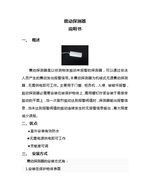
震动探测器是以侦测物体振动来报警的探测器,可以通过非法人员产生的震动发出报警信号。
本震动探测器为机械式无源震动探测器,无需供电即可工作。
主要用于门窗、柜员机,入侵、被破坏报警,振动探测器必需要安装在被保护物体上,需用螺钉拧紧安装于易感受振动的平面上,当一次剧烈振动达到报警阀值时,探测器输出报警信息,当未达到报警阀值的振动连续发生时无报警信息输出,最大限度减少误报。
二、优点
★室外安装有效防水
★无需电源供电即可工作
★灵敏度可调
三、安装方式
震动探测器的安装方式有:
1.安装在保护物体表面
2.嵌入式安装,如预制在墙体内部,对墙体进行保护;安装在设备内部等
注意:在固定震动探测器时,要保持其与地面水平,而且要固定牢靠;选择的保护物体要是不会轻易受外界自然环境的影响而产生剧烈震动,比如自然风
四、灵敏度调节
震动探测器由三部分组成,固定底座、防水外壳、震动探测器,如图:
拆开外壳后,可以看到震动探测器的一侧有如下标识
L:最小灵敏度
M:一般灵敏度
H:最大灵敏度
旋转震动探测器,可以调节其灵敏度。
固定好震动探测器,当H 字样向下与地面垂直时即为最大灵敏度;M字样朝下与地面垂直即为一般灵敏度,L字样朝下与地面垂直时即为最小灵敏度。
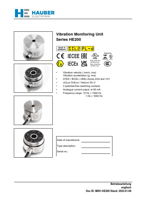
HAUBER-Elektronik GmbH 振动监测单元类型 HE200 操作说明书
BetriebsanleitungenglischDoc ID: M001-HE200 Stand: 2023-01-09Vibration Monitoring UnitSeries HE200• Vibration velocity ( mm/s, rms) Vibration acceleration (g, rms)• ATEX / IECEx / UKEx Zones 2/22 and 1/21 • cULus OrdLoc / HazLoc Div 2 • 2 potential-free switching contacts • Analogue current output: 4–20 mA • Frequency range: 10 Hz – 1000 Hz 1 Hz – 1000 HzOperating instructionsVibration Monitoring UnitType HE200Standard and ATEX / IECEx / UKExVersion: 2023-01-09Attention!Prior to commissioning the product, the instruction manual must be read and un-derstood.All rights reserved, including rights to translation.Subject to modifications.Please contact the company with any questions:HAUBER-Elektronik GmbHFabrikstraße 6D-72622 NürtingenGermanyTel.: +49 (0) 7022 / 21750-0Fax: +49 (0) 7022 / 21750-50*************************www.hauber-elektronik.de1 Contents1Contents (3)2Safety information (5)3Scope of this instruction manual (6)4Vibration Monitoring Unit Type HE200 (6)5Intended Use (6)6Scope of supply (6)7Documents and Certificates (7)8Transfer of liability when operating in potentially explosive atmospheres (7)9Overview of application areas (8)10Example labels (9)11Information on the cULus validity range (10)12Functional safety instructions (11)12.1Safety level / key indicators (11)12.2General notes (11)12.3Instructions for the Fail Safe State (11)13Technical data (12)13.1General data (12)13.2Electrical data (12)13.3Operating range of the vibration monitoring unit (13)13.4Typical frequency response (14)13.5Properties of the integrated cable (15)13.6Mechanical data (15)13.7Housing dimensions (16)14Connection (17)15Functional description (18)15.1Operating conditions (18)15.2Alarm and limit setting (18)15.3Limit values and delay times (19)16Assembly and disassembly (21)16.1General notes (21)16.2Fixing the vibration monitoring unit to the mounting surface (21)16.3Variant HE200.02 (Zone 2 / 22) (22)16.4Tamper protection (23)17Installation and commissioning (24)17.1General notes (24)17.2Earthing concept (24)18Maintenance and repair (25)18.1General notes (25)18.2Troubleshooting Table (25)19Transport, storage and disposal (26)20Coding HE200 (27)21EU and UK Declaration of Conformity (28)2 Safety information2.1 GeneralThe safety instructions are intended to protect people and property from damage and hazardsthat could arise as the result of improper use, incorrect operation or other misuse or devices,especially in explosive areas. Therefore, please read the operating instructions carefully beforeworking on the product or operating it. The operating instructions must be accessible to operat-ing personnel at all times.Please make sure that all documents are present and complete before commissioning or per-forming other work on the product. If the documents have not all been delivered in full or if fur-ther copies are necessary, they can also be obtained in other languages.The product is built according to the latest state of the art. However, hazards to people, machin-ery and systems can still arise as the result of improper handling, unintended use or operationand maintenance by persons inadequately trained on the product.All those who are involved in the installation, operation and maintenance of the product in theoperator’s plant must read and understand the operating instructions.The product may only be assembled, disassembled, installed and repaired by instructed, suffi-ciently trained and authorised personnel.2.2 Symbols usedThis symbol indicates an explosion hazard.This symbol indicates a hazard from electrical current.This symbol indicates safety-related information.This symbol indicates information unrelated to safety.3 Scope of this instruction manualThis instruction manual for the HE200-type vibration monitoring unit applies to the following ver-sions:HE200.00, HE200.01 and HE200.02The variants are functionally identical. The variants HE200.01 and HE200.02 haveadditional certifications and labels which permit use in potentially exclusive atmospheres.For further information, see chapter "Overview of application areas” on page 8.4 Vibration Monitoring Unit Type HE200The HE200 type vibration monitoring unit is used to measure and monitor absolute bearing vib-rations in machines in line with DIN ISO 10816.It offers the following features:•Two limit values and associated delay timings can be adjusted separately.•The two potential-free switching contacts will signal any exceeding of the relevant defined limit values. This can be used to generate a pre-alarm and a main alarm.•Measurement parameter: The rms value of the vibration velocity ( mm/s) orThe rms value of the vibration acceleration (g).•Analogue current output: Interference-free DC signal from 4-20 mA, proportional to the measuring range of the monitoring unit.5 Intended UseType HE200 is used to protect machines and mechanical equipment against undue strong vib-rations. It may only be used in accordance with the specifications listed in the data sheet. It isused exclusively for measuring mechanical vibrations. Main fields of application: Fans, venti-lators, blowers, electric motors, pumps, centrifuges, separators, generators, turbines and similaroscillating mechanical equipment.If the equipment is used in a manner not specified by the manufacturer, theprotection provided by the equipment may be impaired.6 Scope of supplyAll versions include:•Vibration monitoring•Cylinder head screw with hex socket, M8 x 20 mm•Seal label•Operating instructions7 Documents and CertificatesYou can find the following documents and certificates for HE200 type at www.hauber-elektro-nik.de where they can be viewed and downloaded:•EU type examination certificate ATEX Zone 1 / 21, no.: UL 20 ATEX 2421 X Rev. 0•Type examination certificate ATEX Zone 2 / 22, no.: UL 21 ATEX 2570 X•IECEx certificate of conformity, no.: IECEx ULD 20.0022X•UL certificate of conformity, no.: E507077-20210204•UKEx certificate number: UL22UKEX2479X•UKEx certificate number: UL22UKEX2480X•EAC Declaration•Functional safety certificate (SIL 2)•Safety manual SIL28 Transfer of liability when operating in potentially explosive atmospheresThe owner of the system is exclusively liable for the appropriate configuration of the electricalconnections with respect to explosion protection regulations and correct commissioning.If the system is installed by a sub-contractor on behalf of the owner, the system may only becommissioned after the sub-contractor has issued written confirmation in the form of a certificateof installation that the system has been installed correctly and professionally in accordance withthe applicable legal regulations.The operator is obliged to notify the responsible authorities of the initial commissioning of explo-sion-protected systems or system components and their re-commissioning following extensivechanges or maintenance.9 Overview of application areas10 Example labelsVariant 1 - HE200.00.xx.xx.xx.00.000Variant 2 - HE200.00.xx.xx.xx.01.xxxVariant 3 - HE200.02.xx.xx.xx.00.000Variant 4 - HE200.02.xx.xx.xx.01.xxxVariant 5 - HE200.01.xx.xx.xx.00.xxxVariant 6 - HE200.01.xx.xx.xx.02.xxx11 Information on the cULus validity rangeIn order to install the device according to the UL/CSA/IEC standard, the following informationmust be observed.Electrical protectionDevices must be protected by means of fuses, circuit breakers, overheatingprotection, impedance-limiting switches or similar to ensure protection againstexcessive power output if there is a fault in the device. Protection must be ap-plied to supply lines and switching lines.A circuit breaker suitable for 30V/3A according to UL Standard 489/CSA Stan-dard (C22.2) no. 5/IEC 60947-2 must be installed near the device.A fuse suitable according to UL Standard 248/CSA Standard (C22.2) no.248/IEC 60127 must be installed near the device. The fuse must have a slowtriggering characteristic (“T”).Limited temperature rangeThe following temperature ranges apply for variants with integrated cable:12 Functional safety instructions12.1 Safety level / key indicatorsThe HE200 vibration monitoring hardware was tested by TÜV Süd. The results meet the criteriaaccording to SIL2 and Pl-d.Further key indicators and information can be found in the safety manual12.2 General notesA reboot of the vibration monitoring unit must be performed annually in order totest the switching of potential-free switching contacts.While the sensor is in configuration mode, the safety functions are deactivated.12.3 Instructions for the Fail Safe StateWhen the power supply is switched on, the vibration monitoring unit will perform a self-test.During operation, self-tests are performed automatically in cycles. If a self-test fails, the vibrationmonitoring unit switches to the Fail Safe State.In the Fail Safe State all status LEDs are lit, all potential-free switching contacts are open andthe analogue current output supplies 0 mA.13 Technical data13.1 General dataEach sensor has one of the listed measuring and frequency ranges. Furtherranges on request.Please indicate the measuring and frequency range in your request.Tab. 1: General data13.2 Electrical dataTab. 2: Electrical data13.3 Operating range of the vibration monitoring unitThe operating range is independent from the measuring range. It can be derived from the maxi-mum acceleration, which is 16.5 g across all frequencies. The maximum measurable vibrationvelocity is based on the formulav max=∫a maxappliesFor sinusoidal vibration, v max=a max2πfFig. 1: shows the operating range of the vibration monitoring unit, which is limited by the maxi-mum measurable vibration velocity in mm/s depending on the frequency in Hz.Fig. 1: Operating range diagram1 Frequency in Hz2 Vibration velocity in mm/s3 Operating range of the vibration monitoring unitReading example:Tab. 3: Reading example of operating range13.4 Typical frequency response10 Hz–1,000 Hz (standard)The frequency response is recorded using a reference sensor.• 4 Hz. . . 1200 Hz acceleration sensorFig. 2: Typical frequency response 10 Hz–1000 Hz1 Frequency in Hz2 Amplification in dB1 Hz–1000 HzThe frequency response is recorded using two reference sensors.• 1 Hz. . . 10 Hz laser sensor• 10 Hz. . . 1200 Hz acceleration sensorFig. 3: Typical frequency response 1 Hz–1000 Hz1 Frequency in Hz2 Amplification in dB13.5 Properties of the integrated cableTab. 4: Technical data of the integrated cable13.6 Mechanical dataAdditional materials can be found in section "Coding" on page 27.Tab. 5: Mechanical data13.7 Housing dimensionsFig. 4: Housing with M12 connector Fig. 5: Housing with integrated cable 1 M12 connector2Measuring direction1 Cable gland2 Connecting cable 3Measuring directionFig. 6: Housing with integrated cable and clamping sleeve base for metal protection hose 1 Cable gland2 Connecting cable3 Measuring direction4Clamping sleeve base for metal protection hose14 ConnectionVersion: Integrated cableFig. 7: Wiring diagram1 Potential-free switching contact 1 (pin 5: + , Pin 6: -)2 Potential-free switching contact 2 (pin 7: + , Pin 8: -)3 Evaluation unitThe wiring diagram shows the alarm status or the current status!Potential-free switching contacts 1 and 2 are open.15 Functional descriptionIn an explosive atmosphere the vibration monitoring unit HE200 will only be o-pened in a de-energized state.The HE200 type has two limit values Lim1 and LIM2 and the corresponding delay times, which can be adjusted separately. If the defined limit value is exceeded and after the set delay time has expired, the corresponding potential-free switching contact is opened. This can be used to generate a pre-alarm and a main alarm.A subsequent fall below the limit value is also signalled at potential-free switching contacts 1 and 2, i.e. the respective switching contact automatically closes.The HE200 type also has an analogue current output. This supplies direct current of 4-20 mA proportional to the vibration amplitude.15.1Operating conditionsTab. 6: Operating conditions15.2 Alarm and limit settingBy pressing the "Save Config" button, the current configuration is displayed by the LEDs around the HEX switches. For further information, see chapter "Limit values and delay times ” on page 19.The limit values and delay times are calibrated using the respective HEX switch. As soon as a switch position is changed, all LEDs start flashing. Press and hold the "Save Config" button for three seconds to save the configuration. Acceptance of the configuration is signalled by steady lighting up of the LEDs in the selected HEX switch position. The configuration can only be accepted if LIM1 ≤ LIM2.After about five minutes the LEDs turn off automatically.While the sensor is in configuration mode, the safety functions are deactivated.15.3 Limit values and delay timesThe SET rotary button has 16 positions, representing the limit value of an alarm. The measur-ing range of the vibration monitoring unit is divided into 16 linear steps.×SET rotary button positionIn general: Limit value=Upper limit measuring range16Example: Limit settingMeasuring range: 0-32 mm/sSET rotary button Pos.: 8 (9)Limit value: 16 mm/s (18 mm/s)Tab. 7: Limit values for vibration velocitiesTab. 8: Vibration acceleration limit values Delay timesTab. 9: Delay times16Assembly and disassembly16.1General notesAssembly and disassembly work on and with the monitoring unit may only be performed by an authorised specialist familiar with the safety regulations governing handling electrical compo-nents! When using EX-certified monitoring units in potentially explosive atmospheres, the pro-fessional must also be familiar with the relevant safety regulations!Before assembly and disassembly disconnect the monitoring unit from the powersupply! Separate plug connections must always be de-energized! If EX-certified monito-ring is operated in a potentially explosive atmosphere, there is otherwise an explosion hazard, due to spark formation!The monitoring unit housing must be earthed via the fastening - through themachine earth of the mounting surface or through a separate protective conductor (PE)!16.2Fixing the vibration monitoring unit to the mounting surfacePrerequisites• Mounting surface is clean and flat; i.e. free ofpaint, rust, etc.• Threaded hole in mounting surface:15 mm, M8Tools and material • Hex socket key SW 6, SW 8 • Torque wrench SW 6, SW 8 • Cylinder head screw with hex socketM8x20 • Spring washers for M8Work steps and instructions • Unscrew housing cover from housingbase;hex socket key SW 8 • Attach monitoring unit using cylinderhead screws and spring washers with 8 Nm on mounting surface; Torque wrench SW 6 • Screw the housing cover back onto thehousing base and tighten to 5 Nm; Torque wrench SW 8Fastening on mounting surface (1)Tighten housing cover with torque wrench (2)In order to avoid cold welding of the housing cover to the housing base, the thread is treated ex-works with an assembly paste for stainless steel connec-tions.16.3 Variant HE200.02 (Zone 2 / 22)The Zone 2/22 variant may not be operated without the safety clip to guard against ac-cidental disconnection of the plug connection! If operated in a potentially explosive at-mosphere, there is otherwise an explosion hazard, due to spark formation!16.3.1 Attaching the safety clip1. Insert the connecting cable socket into the M12 connector as far as it will go (mind theposition of the code cam).2. Tighten the knurled rotating ring of the socket by hand.3. Attach the safety clip to guard against accidental disconnection of the plug connection.- Place both shell halves of the clip around the plug connection.- Press both shell halves firmly together with your hands until the lock snaps into place.- Place the arrow connected to the two shell halves around the cable and pull it through the eyelet at the other end so that the notice "DO NOT DISCONNECT UNDERVOLTAGE" can be read alongside the cable.Fig. 8: Safety clip Fig. 9: Attached safety clip1 Notice16.3.2 Attaching the protection capAfter disconnecting the plug, the protection cap must be attached to the M12 plug!Detach the safety clip and attach the protection cap.1. Disconnect voltage.2. Pry apart both shell halves of the sleeve with a screwdriver.3. Close off the M12 plug well with the protection cap.Fig. 10: Protection cap Fig. 11: Attached protection cap16.4 Tamper protectionAttach seal labelsThe "SEALED" seal label reveals any unauthorised opening of the housing cover.After installation of the housing cover by the system operator, the seal label shall be attached tothe side above the housing joint.If any tampering is attempted, the seal label is destroyed and the tampering will be visible to thesystem operator.Fig. 12: Seal label17Installation and commissioning17.1General notesInstallation and commissioning of the vibration monitoring unit may only be performed by an authorised specialist familiar with the safety regulations governing handlingelectrical components. When installing and commissioning EX-certified monitoring units in potentially explosive atmospheres, the professional must also be familiar with the rele-vant safety regulations!The commissioning will only be carried out with the housing cover correctly screwed on (tightening torque = 5 Nm)! If EX-certified monitoring is operated in a potentially explosive atmosphere, there is otherwise an explosion hazard, due to spark formation!Protect the connection cable and any extension cable from electrical interfe-rence and mechanical damage! Local regulations and instructions must be ob-served in doing so!17.2 Earthing conceptThe earthing concept stipulates that the sensor cable shield is electrically connected to the sen-sor housing through the knurled nut and is at earth potential on the evaluation unit or the switch cabinet. For longer wires, we recommend separating the disconnecting the shield at the evalua-tion unit (4) to prevent compensating currents through the shield.Fig. 13: Earthing concept HE200 1 Machine earth2 Evaluation unit (measuring instrument, SPS, …)3 Cable shield4 Evaluation unit earth potential5 Optional flexible metal tubing (only available for version with integrated cable)18Maintenance and repair18.1General notesRepair and cleaning work on vibration monitoring units may only be performed by an authorised specialist familiar with the safety regulations governing hand-ling electrical components.Before repair and cleaning disconnect the monitoring unit from the power supply! Separate plug connections must always be de-energized!Immediately replace defective connection cables!A defective vibration monitoring unit must be completely replaced!The vibration monitoring unit HE200 is maintenance-free!18.2 Troubleshooting TableTab. 10: Troubleshooting Table19 Transport, storage and disposalThe sensor must be protected from damaging environmental factors and mechanical damageduring transport with the use of adequate packing.The sensor may not be stored in ambient temperatures outside the permitted operating tempe-rature.The product contains electronic components and must be disposed of properly in accordancewith local laws and regulations.20 Coding HE200000 = M12 connector (standard)020 = 2 m integrated cable050 = 5 m integrated cable100 = 10 m integrated cableDon’t see your desired configuration listed? Please contact us and we can of-fer you a solution for your specific needs.21 EU and UK Declaration of ConformityDeclaration of conformity HAUBER-Elektronik GmbH Fabrikstraße 6D-72622 Nürtingendeclares under our sole responsibility that the products listed below that relate to this declara-tion meet the basic health and safety require-ments of the norms and directives below.Product seriesHE200, HE205, HE250, HE250ATEX AnnexUL International Demko A/S certifies as Notified Body No. 0539 according to the Directive of the Council of the European Community of 26 Feb-ruary 2014 (2014/34/EU) that the manufacturer maintains a quality assurance system for produc-tion that complies with Annex IV of this Directive.UKEx AnnexUL International Demko A/S certifies as Noti-fied Body No. 0843 according to the UK Legis-lative Decree 2016:1107 of December 8, 2016,that the manufacturer maintains a production quality system that complies with Annex IV of this Legislative Decree.Marking and certificatesHE200.02 / HE205.02 / HE250.02 / HE255.02 HE200.01 / HE205.01 / HE250.01 / HE255.01 SignatureNürtingen, 07/11/2022Place and date_______________________________Tobias Bronkal, Managing Owner。
振动探测器原理
振动探测器原理
振动探测器原理是利用振动的感知和测量来检测物体的运动或振荡情况。
振动探测器通常由感应元件和测量系统组成。
感应元件可以是加速度计、压电传感器、光学传感器等。
加速度计是一种常用的感应元件,其工作原理是利用固定在其内部的质量块受到振动时,在坐标轴上产生相对位移,进而导致感应元件内部的电荷变化或电阻变化。
压电传感器则是利用压电效应来感应振动,当物体受到振动时,压电元件会产生电荷或位移,进而生成电信号。
光学传感器则是利用光电二极管或光敏电阻等光学元件,通过接收到的光信号的变化来感应振动。
测量系统则是用来接收、放大和处理感应元件产生的信号。
测量系统根据具体的需要可以有多种形式,包括模拟信号处理电路和数字信号处理器。
在模拟信号处理电路中,信号经过放大、滤波等处理后被转化为测量结果。
数字信号处理器则更进一步,可以利用微处理器或专门的数字处理芯片,将模拟信号转换为数字信号进行处理,并实现更复杂的功能,如数据存储、实时分析等。
根据振动探测器的原理,我们可以通过感应元件的输出信号来分析物体的振动特征,包括振动的强度、频率、相位等。
这些特征可以用于判断物体的运动状态,如是否处于振荡、频率是否稳定等。
同时,振动探测器也可以用于监测物体的结构健康状态,对于预测和预防结构的损坏具有重要意义。
值得注意的是,不同类型的振动探测器适用于不同的应用场景,
需要根据具体需要选择合适的感应元件和测量系统。
此外,振动探测器的精度和可靠性也是值得考虑的因素,因为它们会直接影响到监测结果的准确性和可信度。
震动探测器应用施工分析方案ATM振动探测器解决方案

震动探测器应用施工分析方案(振动传感器)主编:史新华震动探测器_振动探测器_A TM震动探测器_柜员机震动探测器_金库墙体震动探测器等使用环境中旳问题震动探测器振动探测器一、振动探测器YT-JB3是以探测入侵者旳走动或进行多种破坏活动时所产生旳振动信号来作为报警根据,例如,入侵者在进行凿墙、钻洞、破坏门、窗、撬保险柜等破坏活动时,都会引起这些物体旳振动,以这些振动信号来触发报警旳探测器就称为振动探测器。
二、常用旳几种振动探测器旳基本工作原理根据所使用旳振动传感器旳不一样,振动探测器可分为:机械式振动探测器、惯性棒电子式振动探测器、电动式振动探测器、压电晶体振动探测器、电子式全面型振动探测器等多种类型。
不一样类型旳振动探测器其工作机理及安装规定也各有差异,以YT-JB3振动探测器为例,它属于压电晶体振动探测器。
该型振动探测器工作原理是运用压电晶体旳压电效应。
压电晶体是一种特殊旳晶体,它可以将施加于其上旳机械作用力转变为对应大小旳电压,即模拟旳电信号。
此电信号旳频率及幅度与机械振动旳频率及幅度成正比。
运用压电晶体旳压电效应就可做成压电晶体振动探测器,其应用范围广阔。
合用于金库、保险箱、A TM机、钢筋混凝土墙和保险库、玻璃、墙体、钢制铠装柜、自动售卖机和门旳防护。
可监控防护面旳震动状况和温度,检测已知类型旳入侵袭击,例如重锤敲击、钻孔、爆炸、液压工具和热力工具三、振动探测器YT-JB3系统设计规定基站旳振动防盗报警系统规定到达如下旳规定:1、实用性:振动探测器YT-JB3 ,YT-JB3系统方案设计无人值守自助设备特殊环境管理工作需要,如墙体防备、区域保护、门窗保护、ATM保护等。
除具有以上功能外,尚有视频录像、报警系统和监控系统旳联动等实用功能。
由于基站是无人职守,因此在报警系统设置旳过程中考虑到现场报警、语音吓退,等多重防备,最大程度旳赶走或恐吓侵入者,到达保护财产旳作用。
2.可靠性:在偏远旳无人值守旳特殊环境中,震动探测器系统必须保证较强旳稳定性和可靠性,前端振动产品选用先进、成熟、可靠旳产品,是已在类似工程中使用过许多旳,证明能适应室外环境旳硬件,并且在系统故障或事故导致中断后,能保证数据旳精确性、完整性和一致性,并具有迅速恢复旳功能,同步系统具有一整套完毕旳系统管理方略,可以保证系统旳运行安全。
振动入侵探测器 NS-330V NS-330ATM 快速安装指南说明书
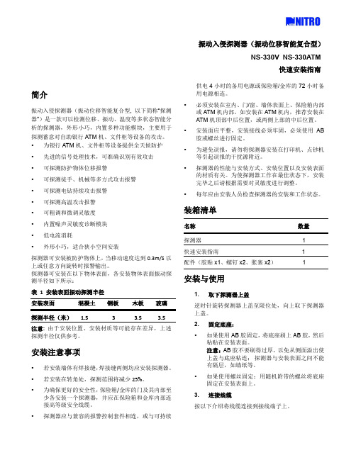
振动入侵探测器(振动位移智能复合型)NS-330V NS-330ATM快速安装指南简介振动入侵探测器(振动位移智能复合型, 以下简称“探测器”)是一款可以检测位移、振动、温度等多状态智能分析的探测器,外形小巧,内置多种功能模块,主要用于探测蓄意对自助银行ATM机、文件柜等设备的攻击。
•为银行ATM机、文件柜等设备提供全天候防护•先进的信号处理技术,可准确识别有效攻击•可探测防护物体位移报警•可探测徒手、机械等多方式攻击报警•可探测电钻持续攻击报警•可探测高温攻击报警•可粗调和微调灵敏度•内置噪声灵敏度诊断模块•低电流消耗•外形小巧,适合狭小空间安装探测器可安装被防护物体上,当移动速度达到0.3m/S以上或任意方向旋转时报警输出。
探测器可安装在以下物体表面,各安装物体表面振动探测半径如下所示:表 1 安装表面振动探测半径安装表面混凝土钢板木板玻璃探测半径(米) 1.5 3 3.5 3.5注意: 由于安装位置、安装材质等可能存在差异,上述探测半径仅供参考。
安装注意事项•若安装墙体有焊接缝,焊接缝两侧均应安装探测器。
•若安装在转角处,探测范围将减少25%。
•为确保更好的安全性,保险箱/金库的门及其内部至少各安装一个探测器,并应在保险箱和金库内部连接高等级安全线缆。
•探测器应与兼容的报警控制套件相连,或与可持续供电4小时的备用电源或保险箱/金库的72小时备用电源相连。
•必须安装在室内、门/窗、墙体表面上、保险箱内部或ATM机内部。
如安装在ATM机内,推荐安装在ATM机顶部中后位置,或两侧上部的中后位置。
•安装面应平整,安装接线必须牢固,必须使用AB 胶或螺丝进行固定。
•为避免误报,请勿将探测器安装在打印机、点钞机等引起误报的干扰源附近。
•探测器的性能与安装方式、安装位置以及安装表面的材质有关。
为使探测器工作在最佳状态下,安装完毕之后请根据需要对灵敏度进行调整。
•每年应由安装人员检查探测器的安装和工作状态。
微动探测原理及仪器介绍

微动探测原理及仪器介绍《微动探测原理及仪器介绍》你有没有想过,在我们的脚下,大地其实一直在悄悄“说话”呢?这就和微动探测有关啦。
微动探测的原理其实就像是在听大地的“心跳”。
我们的地球表面,即使看起来平静,实际上也存在着各种微小的振动,这些振动就叫做微动。
微动的来源可多啦,比如说风轻轻吹过地面、远处车辆行驶引起的微弱震动、还有地下水流悄悄流动时带来的动静,甚至是地球自身内部活动发出的微弱信号。
这些微动就像不同乐器同时在一个大乐队里演奏,各自发出独特的“声音”。
那微动探测怎么从这一堆混合的“声音”里听出有用的信息呢?这里面有个很巧妙的原理。
我们知道,不同的物质对这些微动的传播和反应是不一样的。
就好比在不同的材质上敲鼓,声音传播的速度、频率都会有所不同。
比如在硬邦邦的石头上敲和在软乎乎的泥土上敲,你听到的声音肯定不一样。
大地也是这样,微动在地下不同的地层结构中传播时,它的频率、速度、幅度等特性就会发生变化。
微动探测仪器就像是一个超级灵敏的“耳朵”,它能够捕捉到这些微小的振动信号,然后通过一系列复杂的分析,就像把大乐队里每种乐器的声音都单独挑出来分析一样,找出其中的规律,从而推断出地下的地质结构。
说到微动探测仪器,那可真是个神奇的家伙。
它就像是一个专门为大地听诊的小医生背着的医疗箱。
这个仪器通常有几个重要的部分。
首先是传感器,这是仪器的“耳朵”,它能够非常敏锐地感受到大地的微动。
这些传感器的灵敏度超级高,就像那些能够听到极其细微声音的蝙蝠耳朵一样。
它们被放置在地面上,静静地等待着大地传来的每一丝“颤动”。
然后是数据采集系统,这个部分就像是一个记忆力超强的小助手。
它负责把传感器捕捉到的微动信号记录下来,而且是准确无误地记录,就像一个一丝不苟的秘书在记录重要会议内容一样。
采集到的数据量可是相当大的,因为微动是一直在发生的,所以要记录很多很多的“瞬间”。
最后还有数据处理和分析系统,这就是仪器的“大脑”啦。
它把采集来的海量数据进行分析,就像一个聪明的侦探在分析案件线索一样。
iSensor三轴振动智能传感器iSV 320 iSV 420介绍

产品特点
美观可靠 IP等级高,可水洗,适应外场恶劣环境 全套应用软件支持,无需二次开发
产品特点
TopCloud云端支持,可实现远程跨地域测控
系统应用图
应用图展示如下:
应用范围
工业精确制造、城市工程、爆破工程、交通工程、军工试验等领域的生产作业和试验现场
应用范围
精密机床、发电机组、卷烟机、特种设备等大型机电设备与旋转机械的振动监测 汽车、飞机等振动试验参数测试 桥梁、隧道等重型运输监测和施工监测 爆破工程的冲击与振动监测和安全评估等
谢谢观看
iSensor三轴振动智能传感器 iSV-320/iSV-420介绍
参考资料:爆破工程技术交流论文集
《爆破工程技术交流论文集》是2018年中国铁道出版社出版的图书,作者是北京工程爆破协会、 南京民用爆炸物品安全管理协会、中国铁道学会铁道工程分会爆破专业委员会。
内容介绍
这是一款四川拓普测控的无线智能传感器,集三轴向振动传感器和数字化测量、存储、无线传输 一体,可一键完成三维速度、加速度等振动参数测量。适用于工程爆破振动的现场测量,工程结 构、特种设备和大型机电设备健康监测,实现分布式无人值守在线监测系统。
产品特点
三向振动速度、加速度测量,实时数字化输出
产品特点
数字化智能振动传感器,集成度高,业界体积最小 低频响应可往下低至 0.01Hz,行业领先
产品特点
内置大容量非易失性存储器,达 16 GB,关机数据不丢失
ห้องสมุดไป่ตู้品特点
内置 GPS功能,自动定位功能,支持分布式同步测量 内置 wifi,支持数百支传感器智能组 内置可充锂电,低功耗运行,续航时间长 自适应环境噪声,自动设置触发条件 一流的工业设计,一键独立操作,使用简便 可内置 4G/5G通信 可支持 DSP扩展,实现智能应用 高强度分子材料 +合金材料,
振动传感器D7S:世界上最小的产品规格,高精度地震传感器说明书

Vibration SensorsD7SThe World's Smallest Class Size,High-precision Seismic Sensor.IoT Friendly.The SI value (or spectral intensity) is equivalent to the magnitude of the destructive energy imposed by seismic motion on structures.The SI value, which is the average value of the integrated velocity response spectrum, is an index that expresses the destructive force of seismic motion and is highly correlated with the damage to structures.SI =Sv (T,h)dT∫1 2.5SI value What Is an SI Value?Vibration Sensors D7S9.8mmD7S10.9mmCompact & High-precision Seismic Sensors- Reducing Secondary Disasters from Earthquakes3EarthquakeEarthquake ends.Emergency ActionsWith their high detection accuracy, these Sensors help with measures to prevent secondary damage after earthquakes in a variety of settings.PreventingSecondary DamageShutting Off and Stopping Hazardous Devices - Semiconductors - Chemical plants - Distribution panels456D 7SHelps Prevent Fire and Other Second-ary Disasters after an Earthquake.The World’s Smallest Class Size Seismic Sensor.•Using the SI value, which has a high correlation with the seismic intensity scale that indicates the magnitude of an earthquake, provides higher-precision judgment of seismic intensity scales.•The 3-axis acceleration Sensor and OMRON’s unique SI value calculation algorithm achieve surface-mountable compact modules and low power consumption.•Higher degree of freedom for incorporation into devices and prolonged operation on battery power.•Shutoff output terminal (INT1) operates equivalent to a conventional mechanical vibration sensor and ensures compatibility with mechanical vibration sensors.•I 2C interface is able to obtain earthquake-related information from the Sensor with communications from external devices.Ordering InformationCharacteristics/PerformanceRoHS CompliantRefer to theSafety Precautions on page 9.TypeAppearancePower supply voltageModelSurface-mounting Vibration Sensor2.1 to 5.5 V D7S-A0001ItemModelD7S-A0001Power Supply Voltage 2.1 to 5.5 VCurrent consumption During standby: 90 μA or less Processing (average): 300 μA or less Operating Temperature −30 to 70°C (with no condensation or icing)Storage Temperature −40 to 80°C (with no condensation or icing)Ambient Humidity 25% to 95% (with no condensation or icing)Storage Humidity25% to 95% (with no condensation or icing)Acceleration Detection Range −2,000 to 2,000 galShutoff Output (INT1)Output at seismic intensity level 5 or higher.Communications Interface I 2C Dimensions 10.9 × 9.8 mmInstallation angle±5°7D7SVibration SensorD 7SConnections●Terminal Arrangement●Block Diagram●Circuit DiagramsNo.Signal FunctionDirection Description1VCC Power supply voltage ---2INT1Shutoff outputOUTAn open-drain output.Goes active (ON) when the shutoff judgment condition and collapse detection condition are met.3INT2Processing notification output OUT An open-drain output.Goes active (ON) during earthquake calculations, offset acquisition, and self-diagnostic processing.4SCL I 2C clock IN Pull up the voltage to VCC even when you do not use I 2C.5SDA I 2C dataIN/OUTPull up the voltage to VCC even when you do not use I 2C.6GND Power supply ground ---7SETTING Initial setting input INChanges the Sensor to Initial Installation Mode for an input from an external device.Normal Mode: High Initial Installation Mode: Low8NC Not connected ---Completely floating and cannot be connected to another line.9VCC Power supply voltage ---10GNDPower supply ground---8D7SVibration SensorD 7SOperation ChartDimensions (Unit: mm)D7S-A0001Recommended Mounting Pattern(TOP VIEW)Recommended Mounting ConditionsPeak mounting temperature: 245°C min. (260°C max.)Reflow time: 64 to 80 s (220°C)Reflow repetitions: Up to 29D7SVibration SensorD 7SSafety PrecautionsThis Sensor is a precision device. Do not drop it or subject it to excessive shock or force. Doing so could break it or change its characteristics. Do not use the Sensor if it has been dropped.●Operating Environment•Do not use the Sensor in locations with volatile, flammable, or corrosive gas (organic solvent vapor, sulfite gas, chlorine, sul-fide gas, ammonia gas, etc.) or other toxic gases. They may cause the Sensor to break down.•Do not use the Sensor in locations subject to fresh water, salt water, water drops, or splattering oil.•Do not use the Sensor in an environment where condensation or icing may occur. Moisture freezing on the Sensor may cause output to fluctuate or may cause the Sensor to break down.•Do not use the Sensor in locations subject to direct sunlight. Doing so may cause the Sensor to break down.•Do not use the Sensor in locations subject to direct radiant heat from heating equipment. Doing so may cause the Sensor to break down.•Do not use the Sensor in locations with severe temperature changes. Doing so may cause the Sensor to break down.•Do not use the Sensor in environments with excess mechani-cal stress. Doing so may cause the Sensor to malfunction or break down.•Do not use the Sensor in locations with large vibration or shock. These may cause the Sensor to break down.•Do not use the Sensor in locations with strong electrical or magnetic fields. These may cause the Sensor to break down.●Countermeasures against Noise•The Sensor does not contain any protective circuits. Never allow the electrical load to exceed the absolute maximum rat-ings. Such loads may damage the circuits. If required, install protective circuits so that absolute maximum ratings are not exceeded.•Allow as much space as possible between the Sensor and devices that generate surges or high frequencies (such as high-frequency welders and high-frequency sewingmachines). Attach a surge protector or noise filter on nearby noise-generating devices (in particular, motors, transformers, solenoids, magnetic coils, or other devices that have an induc-tance component).•Wire the Sensor away from high-voltage and large-current power lines in order to prevent inductance noise. It is also helpful to separate conduits and ducts and to use shielded cables.•When using a switching regulator, power supply switching noise may cause malfunctions, so check this before use.●Handling•Static electricity can destroy the Sensor. Take countermea-sures including grounded work benches, floors, and other charged objects and workers.•Do not handle the Sensor in locations with excessive vapor, dust, dirt, etc.•Do not hold the Sensor with pliers, tweezers, or similar tools, and do not subject components to damage or excessive shock due to inadequate adjustment of the mounter.•When placing components near the edge of the PCB or near a connector, make sure that stress is not applied to the Sensor when the device is assembled or when the connector is con-nected or disconnected.•Do not apply any external force to components after soldering until everything has cooled off and do not allow mechanical stress due to PCB warping or other factors.•Under some usage conditions, ultrasound may cause the Sen-sor to resonate and be destroyed. OMRON cannot specify the detailed conditions under which the Sensor will be used, so we assume no responsibility if the Sensor is used in environments where ultrasound is used. If the Sensor must be used in an environment with ultrasound, check its performance in the actual environment beforehand.•Stress due to plastic hardening may change Sensor character-istics. Do not mold seal the Sensor after mounting.•When applying a moisture preventing coating or other coating after mounting the Sensor, select a coating with minimal stress and check operation carefully.•Do not attempt to disassemble or modify the Sensor.•Do not use the Sensor in safety devices or for applications in which Sensor operation would directly affect human life.•Carefully read the precaution in the Instruction Manual before using the Sensor.•In addition, if you use the Sensor under conditions other than those in these specifications, check Sensor operation under those conditions beforehand.●Shipping and Storage•Do not store the Sensor in locations with harmful corrosive gas (organic solvent vapor, sulfite gas, sulfide gas, etc.)•The Sensor is not drip proof, so do not store it anywhere that water might get on it.•Store the Sensor within appropriate temperature and humidity ranges.*Before storing the Sensor in an environment other than the environment recommended by OMRON, evaluate the results in the actual storage environment and judge whether or not storage there is appropriate.•Do not store the Sensor in locations with excessive vapor, dust, dirt, etc.CautionPrecautions for Correct UseMEMO10• Application examples provided in this document are for reference only. In actual applications, confirm equipment functions and safety before using the product.• Consult your OMRON representative before using the product under conditions which are not described in the manual or applying the product to nuclear control systems, railroad systems, aviation systems, vehicles, combustion systems, medical equipment, amusement machines, safety equipment, and other systems or equipment that may have a serious influence on lives and property if used improperly. Make sure that the ratings and performance characteristics of the product provide a margin of safety for the system or equipment, and be sure to provide the system or equipment with double safety mechanisms.Note: Do not use this document to operate the Unit. OMRON CorporationElectronic and Mechanical Components Company Contact: /ecb Cat. No. A252-E1-031216(0316)(O)。
博世 ISN-SM 振动探测器 说明书

以下型号属于 ISN-SM 系列振动探测器:型号特性ISN-SM-50•在混凝土上工作半径为 4 米•50平方米监控区域ISN-SM-80•在混凝土上工作半径为 5 米•80平方米监控区域每款振动探测器均可对物体和表面进行监视,设计紧凑小巧,即便是在狭小的空间内也可轻松安装。
ISN-SM 振动探测器可以监视保险箱、夜间保险箱和自动柜员机。
系统概览当对混凝土、钢铁或合成钢筋之类的材料进行切割或钻孔时,结构的正常振动模式会出现偏差。
SENSTEC 传感器可以将振动偏差转化成电信号。
振动探测器的数字处理功能对信号进行分析,并将它们与用于破坏保险箱、夜间保险箱等物品的常用工具的频率范围进行比较。
如果信号在此频率范围之内,则振动探测器会通过继电器触点传输报警。
基本功能探测振动探测器既可以识别由爆炸物造成的振动,也可以识别由菱形尖钻头、机械和液压冲锤、火焰切割机、热枪或高压水射流切割机等工具造成的振动。
SENSTEC 传感器和数字信号处理功能可以对狭窄的频率范围进行监视,从而提供可靠的探测。
振动探测器可忽略空气移动和噪声等环境条件。
使用 DIP 开关设置灵敏度灵敏度通过 DIP 开关进行选定。
它既可为应用、材料和物体选择相应的灵敏度设置,也可选择现有的任何干扰。
提供以下设置:•钢铁,2.0 米•钢铁,2.5 米•混凝土,4.0 米•用户模式,使用 SensTool 软件SensTool 软件在 PC 上运行的 SensTool 软件提供以下选项:•更改工厂默认设置•监控探测器性能•存储积分信号等信息•选择其它探测器和撞击灵敏度设置固定设备固定设备是 ISN-SM 振动探测器的可选硬件附件。
系统布防时,固定设备会监视保险箱和保险库是否受到热工具与机械工具的破坏以及是否存在非法打开情况。
固定设备组件由探测器板、门板和备用板组成。
探测器板有一个监控微开关和磁控开关。
系统布防时,探测器板内的监控开关会闭合。
如果从门板上拆除探测器,监控开关会打开并触发报警。
震动测试仪
震动测试仪引言:震动测试仪是一种用于测量和分析物体在受到震动或振动时的行为和性能的设备。
它广泛应用于工业、军事、科研和其他领域,以帮助人们了解和改进产品的可靠性和耐久性。
本文将介绍震动测试仪的原理、应用领域和技术参数,以及如何正确使用和维护震动测试仪。
一、原理震动测试仪基于加速度传感器和数据采集系统的原理工作。
当被测试物体发生震动时,加速度传感器可以感知到物体的加速度变化,并将其转换为电信号。
数据采集系统将传感器收集到的电信号转换为数字信号,并进行数据处理和分析。
通过测量和分析物体的加速度、速度和位移等参数,人们可以评估物体的振动行为和性能。
二、应用领域1. 工业领域:震动测试仪在工业生产中被广泛应用于各种产品的质量控制和性能测试。
例如,汽车制造商在生产线上使用震动测试仪来检测汽车零部件的可靠性和耐久性。
此外,电子设备制造商也使用震动测试仪来测试电子产品的抗震性能,以确保其在运输和使用过程中不会受到损坏。
2. 军事领域:在军事领域,震动测试仪被广泛应用于武器、导弹和其他军事设备的研发和测试。
通过对这些设备进行震动测试,可以评估它们在战斗环境中的稳定性和可靠性。
这对于确保军事设备在战斗时的正常运行至关重要。
3. 科研领域:震动测试仪也是科学研究中重要的工具之一。
科学家可以使用震动测试仪来研究物体在不同频率和振幅下的振动行为。
例如,地震学家可以使用震动测试仪来研究地震的发生机制和影响,以便提高地震预警系统的准确性和可靠性。
三、技术参数震动测试仪的技术参数对于用户选择正确的设备和进行合适的测试至关重要。
以下是一些常见的技术参数:1. 频率范围:表示震动测试仪可以测量的频率范围。
不同的设备在此参数方面可能有所不同,用户需根据具体需求选择适合的设备。
2. 加速度范围:指震动测试仪能够测量的最大加速度范围。
该参数通常以重力加速度(g)为单位表示。
3. 准确度:表示设备测量结果与真实值之间的偏差程度。
高准确度的设备可以提供更可靠的测试结果。
振动监测器的工作原理及用途

振动监测器的工作原理及用途
【】振动监测器与振动传感器相似,都是用于振动测量和检测的工具,但振动监测器的精密度比振动传感器更高,所监测的对象也比振动传感器监测的对象更为重要,如高精密的机床等设备,多是使用振动监测器来监测其振动状态。
1、振动监测器的原理
振动监测器的原理和振动传感器有很多的相似之处,它们都是收集振动的机械量,通过系统处理将机械量转化为电量后进行识别。
振动监测器在监测时会对系统接收的电量进行判断,当电量超过一定范围时,振动监测器就会发出警报。
2、振动监测器的功能
振动监测器能对机械设备进行24小时不间断的监控,随时测量机械设备的振动频率,当机械设备的振动频率发生异常时,振动监测器会立刻发出警报,对用户进行提示。
振动监测器的应用可以帮助用户将振动异常所带来的损失降低到最小。
振动监测器的敏感度很高,检测的范围也非常广泛,能够实时检测到任何波形的振动,并采集到各个方向上出现的振动数据。
振动监测器中高性能的产品,可以达到在千分之一秒的时间内,同时采集三个不同方向的振动数据。
3、振动监测器YT-SHK-A的用途
振动监测器的测量灵敏度高、抗干扰能力好,比振动传感器具有更高的可靠性,因此振动监测器更多被应用于精密机床等机械设备的振动检测,及ATM机、保险柜、机动车和库房墙体门窗的防盗监控。
美国伊莱克森(Electro-Sensors)安全监测专家 VS2 振动监测仪 用户手册说明书
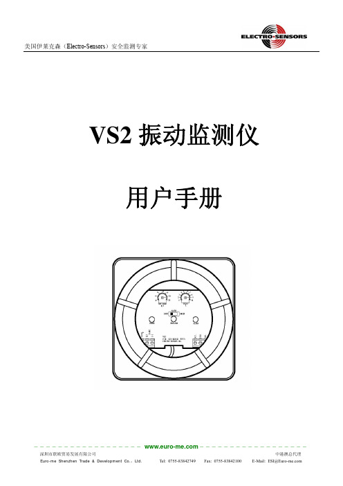
VS2振动监测仪用户手册产品描述VS2(XP)振动监控器将传感器、电路部分和独立的NPN 或继电器输出整合到一个防爆保护壳中。
产品直接安装在设备表面进行监测并当振动级别超过或低于设定值时报警(取决于报警开关设定)。
操作界面/产品尺寸设定面板和开关都位于外壳内部。
更改设定时需移除外盖,完成后重新安装上外盖。
装上外盖状态图(外盖窗口显示)安装:坚固、紧密的连接对于任何振动检测装置都是必要的。
任何松动或谐振都可能会引起误差。
因此,VS2(XP )系列必须牢牢地固定在光滑的平面上。
端口连接方式 电源产品安装 方向:VS2(XP)振动监控器是沿着外壳上传感方向箭头(SENSING DIRECTION)所示轴的方位探测振动,在安装时须确保箭头方向与振动方向一致。
输出 (NPN 输出选项) (继电器输出选项) TB1-1 Case TB1-1 Emitter 继电器 N.C. TB1-2 DC Power(+) TB1-2 Collector Protection Cathode 继电器 Common TB1-3 DC Power(-) TB1-3 Collector 继电器 N.O.产品操作电源指示灯(绿色)…..指示VS2电源情况振动指示灯(绿色)…..指示振动级别在或低于最小可测级别(2 英寸/秒名义)警报指示灯(红色)…..指示警报状态注意:警报是非闭锁的----警报状态仅在振动级别处于警报级别时持续。
超振/低振警报开关…….根据所需功能选择警报类型超振:当振动级别高于设定点级别时报警低振:当振动级别低于设定点级别时报警触发点设定……………..以英寸每秒RMS来设定触发点报警延时设定…………..设定报警延时秒数当振动达到报警级别时,警报会在设定秒数后响起。
同时要求这种振动状态要一直保持至少设定的秒数警报才会响起。
NPN输出选项………….独立NPN输出用于失效保护设备操作(NPN输出需接通电源且非警报状态)工作条件如下:当VS2接通电源且在非警报状态下时开启当VS2未接通电源或在警报状态下时关闭继电器输出选项目……...独立的SPDT继电器输出用于失效保护设备操作(继电器输出输出需接通电源且非警报状态)。
振动探测器使用说明书
振动探测器使用说明书简介振动探测器提供可靠的24小时周界防范,一旦入侵者企图通过爆破、开凿、敲击、钻孔或锯开被保护的窗、门、墙壁及屋顶进入时就能立刻被探测到。
振动探测器采用先进的数字微处理器对来自压电传感器的变化信号进行分析处理。
振动探测器的独特功能是同时对两路独立通道信号进行数字采样处理,由于每个通道具有不同的放大增益,所以提供非常广泛的取样信号分析范围,以确保对振动信号进行精确的量化与分析。
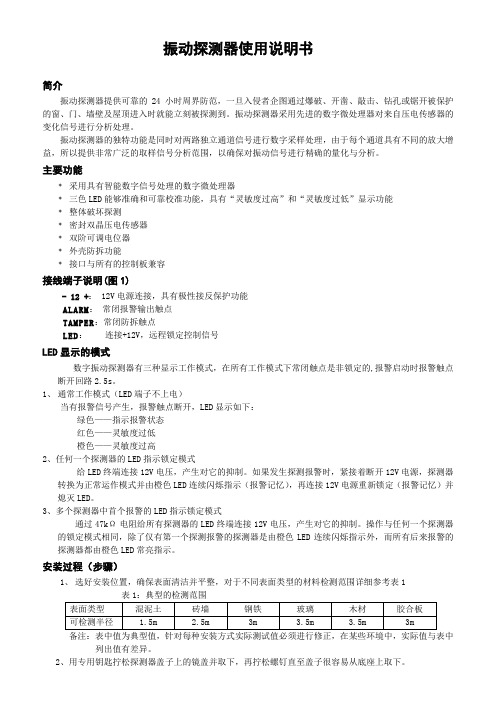
主要功能﹡采用具有智能数字信号处理的数字微处理器﹡三色LED能够准确和可靠校准功能,具有“灵敏度过高”和“灵敏度过低”显示功能﹡整体破坏探测﹡密封双晶压电传感器﹡双阶可调电位器﹡外壳防拆功能﹡接口与所有的控制板兼容接线端子说明(图1)- 12 +: 12V电源连接,具有极性接反保护功能ALARM:常闭报警输出触点TAMPER:常闭防拆触点LED:连接+12V,远程锁定控制信号LED显示的模式数字振动探测器有三种显示工作模式,在所有工作模式下常闭触点是非锁定的,报警启动时报警触点断开回路2.5s。
1、通常工作模式(LED端子不上电)当有报警信号产生,报警触点断开,LED显示如下:绿色——指示报警状态红色——灵敏度过低橙色——灵敏度过高2、任何一个探测器的LED指示锁定模式给LED终端连接12V电压,产生对它的抑制。
如果发生探测报警时,紧接着断开12V电源,探测器转换为正常运作模式并由橙色LED连续闪烁指示(报警记忆),再连接12V电源重新锁定(报警记忆)并熄灭LED。
3、多个探测器中首个报警的LED指示锁定模式通过47kΩ电阻给所有探测器的LED终端连接12V电压,产生对它的抑制。
操作与任何一个探测器的锁定模式相同,除了仅有第一个探测报警的探测器是由橙色LED连续闪烁指示外,而所有后来报警的探测器都由橙色LED常亮指示。
安装过程(步骤)1、选好安装位置,确保表面清洁并平整,对于不同表面类型的材料检测范围详细参考表1备注:表中值为典型值,针对每种安装方式实际测试值必须进行修正,在某些环境中,实际值与表中列出值有差异。
振动测试仪 原理

振动测试仪原理
振动测试仪是一种用于测量和分析物体振动特性的设备。
它的工作原理基于振动传感器和信号处理系统,可以将物体的振动信号转化为电信号并进行分析。
振动测试仪通常包括一个振动传感器,它可以将物体的振动信号转化为电信号。
振动传感器通常采用压电陶瓷的原理,当物体振动时,压电陶瓷会产生电压信号。
这个电压信号可以被连接到信号处理系统中进行分析。
信号处理系统是振动测试仪中的核心部分,它可以将来自振动传感器的电信号进行放大、滤波和数字化处理。
放大可以增加信号的幅值,使得可以更好地分析振动信号。
滤波可以去除信号中的噪声和干扰,提高测量的准确性。
数字化处理可以将信号转化为数字形式,方便进行数据分析和存储。
使用振动测试仪进行振动测量时,需要将振动传感器放置在被测试物体的表面上。
当物体振动时,振动传感器会产生相应的电信号。
信号处理系统会对这个电信号进行处理,得到物体的振动特性,如振动频率、振动幅值等。
振动测试仪广泛应用于工程领域和科学研究中。
它可以用于检测机械设备的运行状况,如机械零件的振动状况、机械系统的结构稳定性等。
它还可以用于分析物体的固有振动特性,如建筑结构的自然频率、音箱的频率响应等。
总之,振动测试仪通过振动传感器和信号处理系统,可以将物
体的振动信号转化为电信号并进行分析,用于研究物体的振动特性和监测设备的运行状况。
- 1、下载文档前请自行甄别文档内容的完整性,平台不提供额外的编辑、内容补充、找答案等附加服务。
- 2、"仅部分预览"的文档,不可在线预览部分如存在完整性等问题,可反馈申请退款(可完整预览的文档不适用该条件!)。
- 3、如文档侵犯您的权益,请联系客服反馈,我们会尽快为您处理(人工客服工作时间:9:00-18:30)。
高安全级别24小时全方位防护
RK66S是高安防级别的震动探测器, 能够7*24小时防护银行金库、保险箱、 ATM自动柜员机,钢筋混凝土墙壁,自 动售卖机和门 采用最先进技术,能够监控到保护 物体表面的震动和稳定变化,并能够探 测到所有已知类型的攻击方式,如铁锤、 金刚钻头、爆破、液压切割以及热切割
RISCO:工业级震动探测器RK66S
选配: 信号发生测试仪
安装底板
典型关键应用场所:高档店铺和ATM
双色LED指示 2. 3. 4.
电源 报警输出 报警记忆 防拆输出
传感器
双进程可调节分压计 – 可灵活 精确地调节 探测灵敏度
震动脉冲计数可选:0,2,4,6
3
以色列EL震动探测器 EWR-VIB
RISCO:工业级震动探测器RK66S
以色列EL震动探测器 EWR-VIB
EWR-VIB震动探测器,通过内 置的分析仪,可以识别真正的暴 力破坏与自然环境的震动。 分析仪的关键部件是单独为EL集 团震动探测器定制设计的集成电 路 具有优秀的品质和可靠性,独特 的外壳外壳设计可防止水珠进入 探测器,每层电路板都有防潮薄 膜保护
RISCO:工业级震动探测器RK66S
采用压电传感器,带有模式识别的数字信号处理 技术 温度传感器可有效检测极低温/高温破坏 探测防区可达5米的工作半径 两档大范围可调节灵敏度 – 可灵活精确地设置探 测灵敏度 双金属外壳 – 抗钻防破坏功能 远程降低灵敏度 – 有效避免ATM机加钞等引起的 误报警 背部、前盖双防拆保护
灵 敏 度 调 节
EL震动探测器 RK66S
两组拨码开关组合设置探测器灵敏度
RISCO:工业级震动探测器RK66S
信号
爆 炸
震动信号
时间
检测周期10 - 80 秒钟可选,时间结束后重新 累计,检测时间越长相当于灵敏度越高
RISCO:工业级震动探测器RK66S
RISCO:工业级震动探测器RK66S
适应所有类型的场合,从小型住宅到大型商业机构 外观小巧精美,有安装底板可以选配
以色列EL震动探测器 EWR-VIB
两个独立通道取样, 可获得大范围动态震动信号 通过对振动信号的频率、能量、振幅和持续时间进行复杂 、精密的分析,精确的量化和分析震动信号 具有脉冲计数功能,当检测到微量震动后,开始30秒倒计 时并计数,期间如检测到剧烈震动,立即产生报警信号 独特的双色LED指示灯,分别指示轻微、沉重的敲击 三种方式组合调整灵敏度 拨码开关5选择调节灵敏度为高档、或低档 拨码开关设置震动脉冲计数:0、2、4、6次 旋钮调节可灵活精确地设置探测灵敏度 低频震动抗干扰能力强、无线射频抗干扰能力强
