台达触摸屏DOPSoft软件使用手册部分
DELTA DOP-B05高色彩宽屏用户友好HMI产品说明书

DOP -B05High Color Wide Screen User-Friendly HMI ProductsB05S111 Instrunction Sheet(1) PrefaceThank you for purchasing DELTA’s DOP-B series. This instruction sheet will be helpful in the installation, wiring and inspection of Delta HMI. Before using the product, please read this instruction sheet to ensure correct use. You should thoroughly understand all safety precautions before proceeding with the installation, wiring and operation. Place this instruction sheet in a safe location for future reference. Please observe the following precautions:Install the product in a clean and dry location free from corrosive and inflammable gases or liquids. Ensure that all wiring instructions and recommendations are followed. Ensure that HMI is correctly connected to a ground. The grounding method must comply with the electrical standard ofthe country (Please refer to NFPA 70: National Electrical Code, 2005 Ed.). Do not disassemble HMI, modify or remove wiring when power is applied to HMI. Do not touch the power supply during operation. Otherwise, it may cause electric shock.If you have any questions during operation, please contact our local distributors or Delta sales representatives.The content of this instruction sheet may be revised without prior notice. Please consult our distributors or download the most updated version at /ia(2) Safety PrecautionsCarefully note and observe the following safety precautions when receiving, inspecting, installing, operating,maintaining and troubleshooting. The following words, DANGER, WARNING and STOP are used to mark safety precautions when using the Delta’s HMI product. Failure to observe these precautions may void the warranty! InstallationWiringOperationD o not modify wiring during operation. Otherwise it may result in electric shock orpersonal injury.N ever use a hard or pointed object to hit or strike the screen as doing this may damage thescreen and let the screen has not respond at all, and then cause HMI to work abnormally.Maintenance and InspectionD o not touch any internal or exposed parts of the HMI as electrical shock may result.Do not remove operation panel while power is on. Otherwise electrical shock may result. W ait at least 10 minutes after power has been removed before touching any HMI terminalsor performing any wiring and/or inspection as an electrical charge may still remain in the HMI with hazardous voltages even after power has been removed. T urn the power off before changing backup battery and check system settings after finishing change. (all data will be cleared after changing battery). B e sure the ventilation holes are not obstructed during operation. Otherwise malfunction may result due to bad ventilation or overheating troubles.Wiring MethodCommunication Wiring(3) Pin Definition of Serial CommunicationNote2: B05S111 models do not support RS-422 flow control function. Note3: COM3 is the extension port (COM2 and COM3 share one physical port)(4) Parts NamesDOP-B05S111 (Front View)A Power LED Indicator (Lights in green when HMI works normally.) BTouch Screen / DisplayDOP-B05S111 (Rear View)(5) DimensionsNote:T=1.6mm(0.063")~ 6mm(0.24")BUnits: mm (inches)(6) SpecificationsL C D M O D U L EDisplay Type 5.6” TFT LCD (65536 colors) Resolution 320 x 234 pixelsBacklight LED Back Light (less than 20,000 hours half-life at 25C) (Note 1)Display Size113.28 x 84.70mm Operation SystemDelta Real Time OS MCU 32-bit RISC Micro-controllerNOR Flash ROMFlash ROM 128 MB(OS System: 30MB / Backup: 16MB / User Application: 82MB)SDRAM 64Mbytes Backup Memory 16MbytesSound EffectOutput Buzzer Multi-Tone Frequency2K ~ 4K Hz85dBAUX N/A Ethernet InterfaceN/AUSB 1 USB Host (Note 2) Ver 1.1 / 1 USB Slave Ver 2.0Memory Card N/ASerial COM PortCOM1 RS-232 (supports hardware flow control)COM2 RS-232RS-485 COM3RS-422RS-485Function Key N/A Perpetual Calendar (RTC) Built-inCooling Method Natural air circulation Safety ApprovalCEUL (Note 3)KCC (Note 3)WaterproofDegree IP65NEMA4OperationVoltage (Note 4) DC +24V -10% ~ +15%(please use isolated power supply)Voltage Endurance AC500V for 1 minute (between charging (DC24V terminal) and FG terminals) PowerConsumption (Note4) 3.0W Backup Battery 3V lithium battery CR2032 x 1Backup BatteryLife It depends on the temperature used and the conditions of usage,about 3 years or more at 25C.Operation Temp. 0oC ~ 50oC Storage Temp. -20oC ~ +60oCAmbient Humidity 10% ~ 90% RH [0 ~ 40C], 10% ~ 55% RH [41 ~ 50C]Pollution Degree 2Vibration IEC 61131-2 compliant 5Hz f 8.3Hz = Continuous: 3.5mm,8.3Hz f 150Hz = Continuous: 1.0gShock IEC 60068-2-27 compliant 15g peak for 11 ms duration, X, Y, Zdirections for 6 timesDimensions (W) x (H) x (D) mm 184 x 144 x 50 Panel Cutout (W) x (H) mm172.4 x 132.4 WeightApprox.670gsupplied to HMI. The life of LED backlight shown here is an estimated value under 25C normal temperature and humidity conditions.2) USB Host port can provide up to 5V/ 500mA of power.3) Some models are in the process of application to UL and KCC certification. For more information, please consult our distributors.4) The value of the power consumption indicates the electrical power consumed by HMI only without connecting to anyperipheral devices. In order to ensure the normal operation, it is recommended to use a power supply which the capacity is 1.5 ~2 times the value of the power consumption.5)The content of this quick start may be revised without prior notice. Please consult our distributors or download the most updated version at /ia/.。
台达 说明书

目录1. WPLSoft简介、安装方法及初始设定1.1. 简介 & 系统需求 (1)1.2. 系统安装 & 设定 (1)1.3. 程序执行 (6)1.4. 参数设定 (8)2. 功能选择列简介2.1. 档案(F)选项 (11)2.2. 通讯(C)选项 (13)2.3. 设定(O)选项 (15)2.4. 窗口(W)选项 (16)2.5. 说明(H)选项 (17)2.6. 编辑(E)选项 (17)2.7. 编译(P)选项 (19)2.8. 批注(L)选项 (20)2.9. 搜寻(S)选项 (21)2.10. 检视(V)选项 (22)3. 建立新档案、开启旧档案及储存档案3.1. 建立新檔 (24)3.2. 开启旧档 (25)3.3. 储存档案 (27)3.4. 另存新檔 (27)4. 阶梯图编辑模式4.1. 阶梯图编辑模式环境 (28)4.2. 基本操作 (28)4.3. 编辑范例 (33)4.4. 辅助编辑 (36)5. 指令编辑模式5.1. 指令编辑模式环境 (51)5.2. 基本操作 (51)5.3. 辅助编辑 (53)6. 批注编辑6.1. 装置批注 (65)6.2. 列批注 (69)6.3. 区段批注 (71)7. 通讯联机模式7.1. 传送资料 (73)7.2. 程序验证 (75)7.3. 密码功能 (76)7.4. 执行/停止PLC (77)7.5. 阶梯图监控 (78)7.6. SFC监控 (80)7.7. 装置监控 (82)7.8. 装置强制ON/OFF (85)7.9. 改变现在值 (88)7.10 缓存器编辑 (90)7.11. PLC 程序内存清除 (92)7.12.PLC状态信息 (94)8. SFC编辑模式8.1.SFC编辑模式环境 (95)8.2.基本操作 (95)8.3.辅助编辑 (106)9. 附录资料资料一操作键及快速键一览表 (114)资料二范例程序 (119)资料三索引功能 (121)。
DOP-4GM01 使用手册说明书

DOP-4GM01使用手册中达电通股份有限公司地址:上海市浦东新区民夏路238号电话:(021)5863-5678传真:(021)5863-0003网站:声 明本手册中的内容将来会有所调整,受条件限制,无法另行通知,更改的内容将会在新版时补充至本手册。
本公司保留在任何时间做出调整或修正本手册内容(包括手册中描述的产品或程序)的权利。
本公司对本手册的内容不做任何承诺、明示或默许担保。
其中包括手册内容的适应性或符合特定使用目的的默许担保,且台达不对用户使用该产品侵犯第三方权利或利益负责。
本公司依据中华人民共和国著作权法,享有及保留一切著作之专属权力,未经本公司同意,不得对本手册进行改编、翻印、改造或效仿等。
All rights reserved目录一、DOP-4GM01模块简介 (4)1.1硬件简介 (5)1.2尺寸图及安装 (6)1.3规格参数 (6)1.4包装清单 (7)1.5订购信息 (7)二、DOP-4GM01使用步骤 (8)2.1设备硬件安装使用 (8)2.2云账号注册 (8)2.3在云平台上新建通道 (10)2.4云账号绑定步骤 (11)2.4.1通过DOPS OFT软件进行绑定 (12)2.4.2通过HMI的系统画面状态查看 (14)2.5、HMI程序的远程上下载 (14)2.6PLC远程上下载 (16)2.6.1 网口PLC的透传 (17)2.6.2 串口PLC的透传 (22)2.7VNC的使用 (27)2.7.1 VNC的设置步骤 (27)2.7.2 通过WEB进行VNC远程 (28)2.7.3 通过手机APP进行VNC远程 (29)一、DOP-4GM01模块简介DOP-4GM01是使用在台达HMI上的一款USB全网通网卡。
其可即插即用,体积小巧轻便,适用场景广,可壁挂或双面胶贴附,易于安装。
其通过台达HMI的USB Host口进行供电和传输数据。
产品依托于DIACloud云平台,可以快速实现HMI程序及其下挂PLC程序的远程上下载、HMI的远程VNC画面等功能。
台达触摸屏安装手册

Wiring Method ¾ Remove the terminal block from the HMI before wiring. ¾ Insert only one wire into one terminal on the terminal block. ¾ If the wiring is in error, perform the wiring again with proper tools. Never use force to remove the terminals or wires. Otherwise, it may result in malfunction or damage. ¾ For the power line that forced to take out, ensure to check wiring again and restart.
台达屏的说明书
5.2 系统设置(System Setting)画面介绍......................................................... 5-5
5.3 上/下载(Upload/Download)画面介绍
....................................................... 5-7
A.12 新增图标输入元件
........................................................................................ A-15
A.13 新增
U盘上下载传输模式
............................................................................ A-16
第四章
Screen Editor使用范例说明
.........................................................4-1
4.1 16位配方使用范例....................................................................................... 4-1
A.6 新增
U盘报警选项
....................................................................................... A-6
A.7 新增
HMI内部系统参数................................................................................ A-8
Delta DOP-B10 HMI 产品说明书
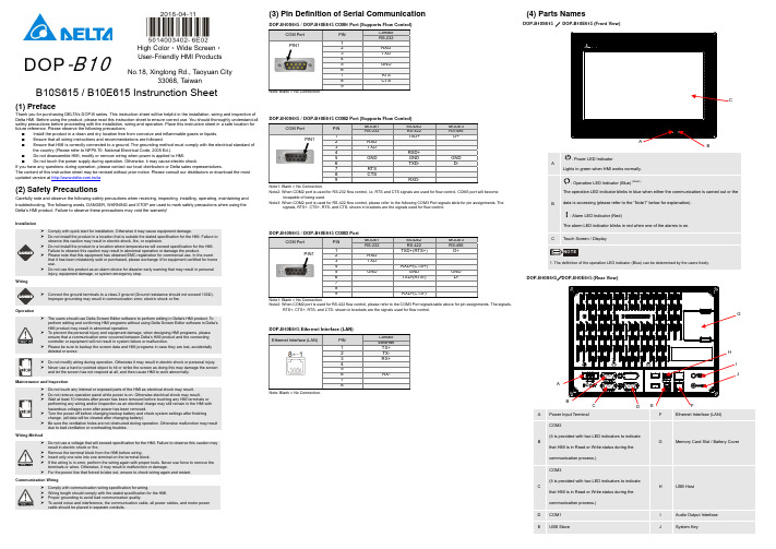
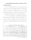
DOP -B10High Color ‧Wide Screen ‧User-Friendly HMI ProductsNo.18, Xinglong Rd., Taoyuan City33068, TaiwanB10S615 / B10E615 Instrunction Sheet(1) PrefaceThank you for purchasing DELTA’s DOP-B series. This instruction sheet will be helpful in the installation, wiring and inspection of Delta HMI. Before using the product, please read this instruction sheet to ensure correct use. You should thoroughly understand all safety precautions before proceeding with the installation, wiring and operation. Place this instruction sheet in a safe location for future reference. Please observe the following precautions: ⏹ Install the product in a clean and dry location free from corrosive and inflammable gases or liquids. ⏹ Ensure that all wiring instructions and recommendations are followed. ⏹ Ensure that HMI is correctly connected to a ground. The grounding method must comply with the electrical standard ofthe country (Please refer to NFPA 70: National Electrical Code, 2005 Ed.). ⏹ Do not disassemble HMI, modify or remove wiring when power is applied to HMI. ⏹ Do not touch the power supply during operation. Otherwise, it may cause electric shock.If you have any questions during operation, please contact our local distributors or Delta sales representatives.The content of this instruction sheet may be revised without prior notice. Please consult our distributors or download the most updated version at /ia(2) Safety PrecautionsCarefully note and observe the following safety precautions when receiving, inspecting, installing, operating, maintaining and troubleshooting. The following words, DANGER, WARNING and STOP are used to mark safety precautions when using the Delta’s HMI product. Failure to observe these precautions may void the warranty! InstallationWiringOperationD o not modify wiring during operation. Otherwise it may result in electric shock or personal injury. N ever use a hard or pointed object to hit or strike the screen as doing this may damage the screenand let the screen has not respond at all, and then cause HMI to work abnormally.Maintenance and InspectionD o not touch any internal or exposed parts of the HMI as electrical shock may result.Do not remove operation panel while power is on. Otherwise electrical shock may result. W ait at least 10 minutes after power has been removed before touching any HMI terminals orperforming any wiring and/or inspection as an electrical charge may still remain in the HMI withhazardous voltages even after power has been removed. T urn the power off before changing backup battery and check system settings after finishingchange. (all data will be cleared after changing battery). B e sure the ventilation holes are not obstructed during operation. Otherwise malfunction may resultdue to bad ventilation or overheating troubles.Wiring MethodCommunication Wiring(3) Pin Definition of Serial CommunicationDOP-B10S615 / DOP-B10E615 COM1 Port (Supports Flow Control)COM PortPINContact RS-2321 2 RXD3 TXD 45 GND 67 RTS 8 CTS9Note: Blank = No Connection.DOP-B10S615 / DOP-B10E615 COM2 Port (Supports Flow Control)COM PortPINMODE1 MODE2 MODE3 RS-232RS-422RS-4851 TXD+ D+2 RXD3 TXD 4RXD+5 GND GND GND 6TXD- D- 7 RTS 8 CTS9 RXD-Note1: Blank = No Connection.Note2: When COM2 port is used for RS-232 flow control, i.e. RTS and CTS signals are used for flow control, COM3 port will becomeincapable of being used.Note3: When COM2 port is used for RS-422 flow control, please refer to the following COM3 Port signals table for pin assignments. Thesignals, RTS+, CTS+, RTS- and CTS- shown in brackets are the signals used for flow control.DOP-B10S615 / DOP-B10E615 COM3 PortCOM PortPINMODE1 MODE2 MODE3 RS-232RS-422RS-4851 TXD+(RTS+) D+2 RXD3 TXD4 RXD+(CTS+)5 GND GND GND6 TXD-(RTS-) D-789 RXD-(CTS-)Note1: Blank = No Connection.Note2: When COM2 port is used for RS-422 flow control, please refer to the COM3 Port signals table above for pin assignments. The signals,RTS+, CTS+, RTS- and CTS- shown in brackets are the signals used for flow control.DOP-B10E615 Ethernet Interface (LAN)Ethernet Interface (LAN)PINContact Ethernet1 TX+2 TX-3 RX+ 45 6 RX-7 8Note: Blank = No Connection.(4) Parts NamesDOP-B10S615 / DOP-B10E615 (Front View): Power LED Indicator: Operation LED Indicator (Blue) : Alarm LED Indicator (Red)DOP-B10S615/DOP-B10E615 (Rear View)APower Input Terminal FEthernet Interface (LAN)BCOM2(It is provided with two LED indicators to indicate that HMI is in Read or Write status during the communication process.) GMemory Card Slot / Battery CoverCCOM3(It is provided with two LED indicators to indicate that HMI is in Read or Write status during the communication process.) HUSB HostD COM1 I Audio Output Interface EUSB SlaveJSystem KeyPIN1PIN1PIN1EFACDJG(5) DimensionsDOP-B10S615 / DOP-B106515Note:T=1.6mm(0.063")~6mm(0.24")+1.0+0.04"(6) SpecificationsDOP-B10S615DOP-B106515L C D M O D U L EDisplay Type 10.1” Widescreen TFT LCD(65536 colors)Resolution 1024 x 600 pixelsBacklight LED Back Light (less than 10,000 hours half-life at 25oC)(Note 1)Display Size 226 x 128.7mm Operation SystemDelta Real Time OS MCU 32-bit RISC Micro-controllerNOR Flash ROMFlash ROM 128 MB(OS System: 30MB / Backup: 16MB / User Application: 82MB)SDRAM 64Mbytes Backup Memory 16MbytesSound Effect OutputBuzzer Multi-Tone Frequency (2K ~ 4K Hz )/85dBAUXN/A Stereo output Ethernet Interface N/AIEEE 802.3, IEEE 802.3u10/100 Mbps auto-sensing(has built-in isolated power circuit(Note 3))USB 1 USB Host(Note 2)Ver 1.1 / 1 USB Slave Ver 2.0Memory CardSD Card (supports SDHC)Serial COM PortCOM1RS-232 (supports hardware flow control)COM2 RS-232/RS-422/RS-485 RS-232 / RS-422 / RS-485(has built-in isolated power circuit (Note 3))COM3RS-232/RS-422/RS-485RS-232 / RS-422 / RS-485(has built-in isolated power circuit (Note 3)) Function Key N/A Perpetual Calendar(RTC) Built-inCooling Method Natural air circulation Safety Approval CE /UL(Note 4)/KCC(Note 4)Waterproof Degree IP65/NEMA4Operation Voltage(Note 5)DC +24V (-10% ~ +15%)(has built-in isolated power circuit (Note 3))Voltage Endurance AC500V for 1 minute (between charging (DC24V terminal) and FG terminals)Power Consumption(Note 5)12WBackup Battery 3V lithium battery CR2032 x 1Backup Battery Life It depends on the temperature used and the conditions of usage, about 3 yearsor more at 25oC.Operation Temp. 0oC ~ 50oC Storage Temp.-20oC ~ +60oCAmbient Humidity10% ~ 90% RH [0 ~ 40o C], 10% ~ 55% RH [41 ~ 50oC]Pollution Degree 2Vibration IEC 61131-2 compliant 5Hz ≦f <8.3Hz = Continuous: 3.5mm, 8.3Hz ≦f ≦150Hz= Continuous: 1.0gShock IEC 60068-2-27 compliant 15g peak for 11 ms duration, X, Y, Z directions for 6timesDimensions(W) x (H) x (D) mm 272 x 200 x 61 Panel Cutout (W) x (H) mm261.3 X 189.3 WeightApprox.1520gThe life of LED backlight shown here is an estimated value under 25oC normal temperature and humidity conditions. 2) USB Host port can provide up to 5V/ 500mA of power.3) The withstand voltage of the isolated power circuit is 1500V peak for 1 minute.4) Some models are in the process of application to UL and KCC certification. For more information, please consult our distributors. 5)The value of the power consumption indicates the electrical power consumed by HMI only without connecting to any peripheraldevices. In order to ensure the normal operation, it is recommended to use a power supply which the capacity is 1.5 ~2 times the value of the power consumption.6)The content of this quick start may be revised without prior notice. Please consult our distributors or download the most updated version at /ia/.DOP -B10Yüksek Renk ‧Geni ş Ekran ‧Kullan ım ı Kolay HMI ÜrünleriNo.18, Xinglong Rd., Taoyuan City33068, TaiwanB10S615 / B10E615 Bilgi Döküman ı(1) ÖnsözDELTA’n ın DOP-B serisi operatör panellerini seçti ğiniz için te şekkürler. Bu bilgi döküman ı Delta HMI kurulum, ba ğlant ı, bak ım ve kontrolünde kullan ıc ıya yard ımc ı olacakt ır. Do ğru kullan ım için ürünü kullanmadan önce bu döküman ı mutlaka okuyunuz. Kurulum, ba ğlant ı ve çal ışma yapmadan önce güvenlik uyar ılar ın ı tamamen anlad ığın ızdan emin olunuz. Bu döküman ı daha sonra da kullanmak için iyi muhafaza ediniz. Lütfen a şa ğıdaki güvenlik uyar ılar ına dikkat ediniz: ⏹ Ürünün kurulumunu yan ıc ı gaz ve s ıv ılardan uzak kuru ve temiz ortamlara yap ın ız. ⏹ Ba ğlant ılar ı yaparken tüm ba ğlant ı kurallar ın ın sa ğland ığından emin olunuz.⏹ HMI’n ın toprak ba ğlant ıs ın ın do ğru yap ıld ığından emin olunuz. Topraklama metodunun ürünün kuruldu ğu ülkestandartlar ına uygun oldu ğuna emin olunuz (NFPA 70: National Electrical Code, 2005 Ed.). ⏹ HMI enerjili iken kablo ba ğlant ıs ı yapmay ın ız ya da sökmeyiniz.⏹ Çal ışma s ıras ında enerji besleme terminallerine dokunmay ın ız. Aksi halde elektrik şoku olabilir. Ürünün kullan ım ı ile ilgili sorular ın ız için, lütfen teknik servisimizle ba ğlant ıya geçiniz.Herhangi bir ihbara gerek kalmaks ız ın bu bilgi döküman ın ın içeri ği de ği ştirilebilir. Güncellenmi ş versiyonu elde etmek için teknik servise dan ışabilir veya internet adresinden indirebilirsiniz. /ia(2) Güvenlik Uyar ılar ıÜrünü al ırken, kontrol ederken, kurulumunu yaparken, çal ışt ır ırken, bak ım ve ar ıza te şhisi yaparken a şa ğıdaki güvenlik uyar ılar ına dikkat ediniz. DANGER, WARNING, ve STOP ba şl ıklar ı DELTA HMI ürününü kullan ırken yap ılmas ı gerekenleri dikkat çekmek için kullan ılm ışt ır. Ürünün garantisini muhafaza etmek için bu uyar ılara mutlaka dikkat ediniz!KurulumBa ğlant ıÇal ışmaÇal ışma s ıras ında kablo ba ğlant ılar ın ı de ği ştirmeyiniz. Aksi halde elektrik şokuna veyaki şisel zararlara sebep olabilir. D okunmatik ekrana sert ve sivri nesneler kullanarak basmay ın ız. Aksi halde HMI ekran ızarar görebilir, komutlara cevap veremeyebilir ve HMI’n ın anormal çal ışmas ına sebep olabilir.Bak ım ve KontrollerH MI içindeki devre elemanlar ına dokunmay ın ız aksi halde elektrik şoku meydana gelebilir. Enerjili iken operatör paneli ba ğlant ılar ına müdahale etmeyiniz. Aksi halde elektrik şokumeydana gelebilir. H MI enerjisi kesildikten sonra HMI üzerinde tehlikeli seviyede elektrik şarj voltaj ıkalabilece ğinden ürüne dokunmadan ve ba ğlant ılara müdahale etmeden önce en az 10 dakika beklenilmesi tavsiye edilir. P ili de ği ştirmeden önce ürünün enerjisini kesiniz ve pili de ği ştirdikten sonra sistemayarlar ın ı kontrol ediniz. (Pil de ği ştirildikten sonra tüm datalar silinecektir). Çal ışma s ıras ında havaland ırma deliklerinin t ıkal ı olmad ığından emin olunuz. Aksi haldekötü havaland ırmadan veya a şır ı s ıcakl ıktan dolay ı ürün zarar görebilir.Ba ğlant ı MetoduHaberle şme Ba ğlant ıs ı(3) Seri Haberle şme Pin Açıklamalar ıDOP-B10S615 / DOP-B10E615 COM1 Port (Flow Control destekler)COM PortPINBa ğlantı RS-2321 2 RXD3 TXD 45 GND 67 RTS 8 CTS9Not: Bo ş pin = Ba ğlant ı yok.DOP-B10S615 / DOP-B10E615 COM2 Port (Flow Control destekler)COM PortPINMOD 1 MOD 2 MOD 3 RS-232RS-422RS-4851 TXD+ D+2 RXD3 TXD 4RXD+5 GND GND GND 6TXD- D- 7 RTS 8 CTS9 RXD-Not 1: Bo ş pin = Ba ğlant ı yap ılmaz.Not 2: COM2 portu RS-232 flow control kullan ılaca ğı zaman, RTS ve CTS sinyalleri flow control olarak kullan ıl ır, COM3 portu kullan ılamaz.Not 3: COM2 portu RS-422 flow control kullan ılaca ğı zaman, lütfen a şa ğıdaki COM3 port pin sinyal çık ışlar ın ı inceleyiniz. Paranteziçinde gösterilen RTS+, CTS+, RTS- ve CTS- sinyalleri flow control olarak kullan ıl ır .DOP-B10S615 / DOP-B10E615 COM3 PortCOM PortPINMOD 1 MOD 2 MOD 3 RS-232RS-422RS-4851 TXD+(RTS+) D+2 RXD3 TXD4 RXD+(CTS+)5 GND GND GND6 TXD-(RTS-) D-789 RXD-(CTS-)Not 1: Bo ş pin = Ba ğlant ı yap ılmaz.Not 2: COM2 portu RS-422 flow control kullan ılaca ğı zaman, lütfen yukar ıdaki COM3 port pin sinyal çık ışlar ın ı inceleyiniz.Parantez içinde gösterilen RTS+, CTS+, RTS- ve CTS- sinyalleri flow control olarak kullan ıl ır .DOP-B10E615 Ethernet Arabirim (LAN)Ethernet Arabirim (LAN)PINBa ğlant ı Ethernet1 TX+2 TX-3 RX+ 45 6 RX-7 8Not: Bo ş pin = Ba ğlant ı yap ılmaz .(4) Parça İsimleriDOP-B10S615 / DOP-B10E615 (Ön Görünüm): : : DOP-B10S615/DOP-B10E615 (Rear View)APower Giri ş TerminalFEthernet Arabirim (LAN)B COM2(Haberle şme s ıras ında HMI’n ın yazma veokuma durumunu gösteren iki LED indikator sa ğlar .)G Memory Card Slot / Pil Kapa ğıCCOM3(Haberle şme s ıras ında HMI’n ın yazma ve okuma durumunu gösteren iki LED indikator sa ğlar .)HUSB HostD COM1 I Audio Çık ış ArabirimiEUSB SlaveJSistem Tu şuPIN1PIN1PIN1EFACDJG(5) ÖlçülerDOP-B10S615 / DOP-B10E615Note:T=1.6mm(0.063")~6mm(0.24")+1.0+0.04"(6) ÖzelliklerDOP-B10S615 DOP-B10E615L C D M O D ÜLDisplay Tipi 10.1” Geni ş Ekran TFT LCD(65536 renk)Çözünürlük 1024 x 600 pikselArka I şık LED Ayd ınlatma (25oC yar ım ömürde 10,000 saatden az)(Not 1)Display Ölçüsü 226 x 128.7mm İşletim SistemiDelta Real Time OS MCU 32-bit RISC Micro-controllerNOR Flash ROMFlash ROM 128 MB(OS Sistem: 30MB / Backup: 16MB / Uygulama: 82MB)SDRAM 64Mbytes Backup Memory 16MbytesSes Efekt Çık ışı Buzzer Multi-Tone Frekans (2K ~ 4K Hz) / 85dB AUX N/A Stereo çık ışEthernet ArabirimN/A IEEE 802.3, IEEE 802.3u10/100 Mbps oto-alg ılama(dahili izole güç devresi (Not 3))USB 1 USB Host(Note 2)Ver 1.1 / 1 USB Slave Ver 2.0Memory CardSD Card (SDHC destekler)Seri COM PortCOM1RS-232 (hardware flow control destekler)COM2 RS-232/RS-422/RS-485 RS-232 / RS-422 / RS-485(dahili izole güç devresi (Not 3)) COM3RS-232/RS-422/RS-485RS-232 / RS-422 / RS-485(dahili izole güç devresi (Not 3))Fonksiyon Tu şu N/A Gerçek Zaman Saati (RTC) DahiliSo ğutma Metodu Do ğal Hava So ğutma Güvenlik Onay ı CE /UL(Note 4)/KCC(Note 4)Su geçirmezlik derecesi IP65/NEMA4Çal ışma Voltaj ı(Not 5)DC +24V (-10% ~ +15%)(dahili izole güç devresi (Not 3))Dayanma Voltaj ı 1 dakika için AC500V (DC24V terminal ve FG terminalleri aras ında)Güç Tüketimi(Not 5)12WBackup Battery 1 adet 3V lityum pil CR2032Backup BatteryÖmrü Kullan ım ko şullar ına ve ortam s ıcakl ığına ba ğl ı, 25oC’de 3 y ıl veya daha fazla.Çal ışma S ıcakl ığı 0oC ~ 50oC Saklama S ıcakl ığı-20oC ~ +60oCRutubet Oran ı 10% ~ 90% RH [0 ~ 40o C], 10% ~ 55% RH [41 ~ 50oC]Kirlenme Derecesi 2Titre şim IEC 61131-≦2 uyumlu 5Hz f <8.3Hz = Sürekli: 3.5mm,≦≦8.3Hz f 150Hz = Sürekli: 1.0gŞokIEC 60068-2-27 uyumlu 11ms süresince 15g pik,X, Y, Z yönünde 6 defaÖlçüler(W) x (H) x (D) mm 272 x 200 x 61 Panel Kesim (W) x (H) mm261.3 X 189.3 A ğırl ıkYakla şık 1520ggösterilen arka ışık LED ayd ınlatma ömrü 25 derecede normal s ıcakl ık ve rutubet ortam ında tahmin edilen de ğerlerdir. 2) USB Host port 5V/ 500mA güç sa ğlar. 3) İzoleli güç devresinin 1 dakika için peak de ğeri 1500V.4) Baz ı modeller için UL ve KCC ba şvurusu yap ılm ış ve i şlem a şamas ındad ır. Daha fazla bilgi için teknik servisimizle ba ğlant ıyageçebilirsiniz. 5) Güç tüketimi de ğeri sadece HMI için olup hiç bir harici cihaza ba ğl ı de ğilken ki de ğerdir. Normal çal ışmay ı garanti alt ına almak içinözelliklerde belirtilen güç de ğerinin 1.5 veya 2 kat ı güç tüketimini kar şılayacak bir güç kayna ğı ile kullan ılmas ı önerilir.6) Herhangi bir ihbar olmadan bu döküman ın içeri ği de ği ştirilebilir. En son güncellenmi ş halini firmam ızdan talep edebilir yada a şa ğıdakilink adresinden indirebilirsiniz /ia/.DOP-B10高彩‧寬螢幕‧友善人機介面No.18, Xinglong Rd., Taoyuan City33068, TaiwanB10S615 / B10E615安裝說明(1) 一般注意事項感謝您使用本產品,本人機介面安裝說明書提供DOP-B系列人機介面的相關資訊。
DELTA DOP-eServer 软件说明书

Revision Oct, 2010
2-1
第二章 軟體安裝
2. 在 Windows 視窗下,双击安裝程序執行文件后,系統自動開始安裝,而且屏幕中間會 顯示信息對話框,可選擇安裝過程中的語言。
選擇好后,按【OK】鍵,請您確認 eServer 系統將安裝的磁盘及目錄名稱。本系統的 默认路径為 C:\Program Files\Delta Industrial Automation\DOP eServer 1.0; 您可以自行變更所要安裝的磁盘位置以及目錄名稱。
eServer_M_SC_20101023
修订记录
发行时间 2010/10/23 发行版本 eServer-001 修订内容 初版
Revision Oct, 2010
目錄
第一章
1.1 1.2 1.3
簡介
eServer 簡介..................................................... 1-1 人機支持型號 .................................................... 1-2 操作環境需求 .................................................... 1-2
3.5
制作 Runtime 捷径 ................................................ 3-7
第四章
4.1
Excel 取樣設定說明
詳細設定說明 .................................................... 4-1 4.1.1 連結..................................................... 4-1
dopsoft使用流程

dopsoft使用流程下载温馨提示:该文档是我店铺精心编制而成,希望大家下载以后,能够帮助大家解决实际的问题。
文档下载后可定制随意修改,请根据实际需要进行相应的调整和使用,谢谢!并且,本店铺为大家提供各种各样类型的实用资料,如教育随笔、日记赏析、句子摘抄、古诗大全、经典美文、话题作文、工作总结、词语解析、文案摘录、其他资料等等,如想了解不同资料格式和写法,敬请关注!Download tips: This document is carefully compiled by theeditor. I hope that after you download them,they can help yousolve practical problems. The document can be customized andmodified after downloading,please adjust and use it according toactual needs, thank you!In addition, our shop provides you with various types ofpractical materials,such as educational essays, diaryappreciation,sentence excerpts,ancient poems,classic articles,topic composition,work summary,word parsing,copy excerpts,other materials and so on,want to know different data formats andwriting methods,please pay attention!Dopsoft 使用流程。
1. 安装 Dopsoft.从官方网站下载安装包。
DOPsoft软件触摸屏使用指导

台达触摸屏Leabharlann 用指导以上这些是所有控件的共通的操作流程,元件的具体属性,以及作用,各位老师可以参考那天拷过去的手册。
1、双击打开图标
2、
3、点击菜单栏中的“文件”,点击“新建(N)”出现此对话框。
4、选择FX2N系类的PLC
5、点击完成后,可以看到如下界面
6、创建一个交替型按钮控件
7、控件属性对话框,此对话框内容和属性表视窗内容一样,两者都可以更改属性
8、输入对话框
9、属性对话框
10、换画面按钮
11、换画面属性对话框
doptouch操作规程

doptouch操作规程Doptouch操作规程1. 安全操作在使用Doptouch之前,必须了解操作规程和安全事项。
1.1 只有经过训练的人员才能操作Doptouch,未经授权的人员禁止使用。
1.2 在使用Doptouch之前,必须穿着适当的个人防护装备,包括手套和护目镜。
1.3 在使用Doptouch时,必须将手指放在指定的触摸区域,避免触摸其他部位,以免造成误操作或伤害。
1.4 当操作完成后,将Doptouch关闭,并断开电源。
1.5 在维护和保养Doptouch时,必须遵循所有安全操作规程,如断开电源、戴上手套和护目镜等。
2. 操作准则当使用Doptouch时,必须严格遵循以下操作准则。
2.1 在操作Doptouch之前,先仔细阅读相关的操作手册和说明书,确保了解所有功能和操作要点。
2.2 在启动Doptouch之前,确保所有连接线都正确连接,并检查所有控制按钮和触摸区域是否工作正常。
2.3 在使用Doptouch时,应使用轻柔的触摸,避免使用过多力量,以免损坏设备。
2.4 在操作Doptouch时,应依次按照指示进行操作,避免跳过任何步骤。
2.5 当操作Doptouch时,如果遇到故障或异常情况,应立即停止操作,并联系专业人员进行维修或处理。
3. 日常维护对Doptouch进行日常维护是确保其正常工作的关键。
3.1 每天使用Doptouch之前,应检查所有连接线是否牢固且未损坏。
3.2 定期清洁Doptouch的触摸区域和屏幕,以保持其清洁和灵敏度。
3.3 在保养Doptouch时,应使用合适的清洁剂和工具,并遵循清洁剂和工具的使用说明。
3.4 定期检查Doptouch的电源线和插头,确保其安全可靠。
3.5 如果发现Doptouch有任何故障或损坏,应立即停止使用,并联系专业人员进行维修或处理。
4. 培训和操作记录为了确保操作的安全和有效性,应进行培训和记录。
4.1 所有操作Doptouch的人员,必须接受相关的培训和指导,并在培训过程中掌握操作技巧和安全事项。
如何设置人机界面画面切换功能

如何设置人机界面画面切换功能人机界面是工控领域常见的器件,是操作人员与设备之间交互的桥梁。
操作人员通过触摸屏控制、监视设备。
对设备来说,通过触摸屏的使用极大的减少了人机交互按钮、指示灯等的使用。
既节省了操作台的空间、又美化了设备。
人机界面在设备具有较多的控制按钮、指示灯等功能选项时。
可以在人机界面设置多个页面显示,依照功能单元等区分,将一页放置不下的器件放置到不同的页面。
在需要的时候,通过页面切换按钮切换画面。
这里昌晖仪表就给大家介绍如何设置人机界面画面切换功能。
人机界面编程环境为台达DOPSoft软件,如下为前期建立的工程背景。
1、在菜单栏,点击“画面”弹出如下所示的快捷菜单,并点击“新画面”;2、弹出如下所示的对话框,画面名称输入“自动运行画面”,画面类型选择“一般画面”,点击“确定”按钮。
完成画面的新建;3、使用同样的方法,建立“手动运行画面”、“状态监视画面”、“参数设置画面”、“报警查询界面”、“帮助画面”。
画面建立后如下图所示。
4、在画面导航器上选择需要配置的画面“自动运行画面”,然后在菜单栏点击“画面”-“画面属性”。
5、弹出页面设置对话框;并在页面设置对话框复选“需要基底画面”-“单一基底”-“1-”-“确定”。
完成显示页面的背景画面的设置。
6、以相同的方式,对其他页面设置背景画面。
设置完成后如下图所示。
7、选择“手动运行页面”,点击界面左侧文本工具,然后在画面拖动鼠标,创建文本框。
8、鼠标双击创建的文本框,在弹出的对话框中,选择“内文”-文字输入框中输入“手动运行画面”,设置文字大小为36,点击“确定”。
使用相同的方式对其他页面创建显示页名。
9、在背景画面中,双击“手动画面”按钮,在弹出的对话框中,选择“一般”-“设定”。
10、在弹出的对话框的画面名称区域,选择“手动运行画面”-“确定”。
完成页面切换功能的创建。
使用相同的方式创建其他几个按钮的功能。
11、创建完成后,点击工具栏中的仿真按钮,显示仿真画面如下,通过点击画面中的各个按钮,画面在各个页面切换。
台达触摸屏一拖二或一拖多组网连接台达PLC
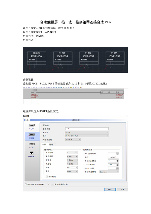
台达触摸屏一拖二或一拖多组网连接台达PLC
硬件:DOP-100系列触摸屏,DVP系列PLC
软件:DOPSOFT,WPLSOFT
组网方式:RS485。
组网方法:
参数设置:
分别把PLC1、PLC2、PLC3的站地址设为1、2和3。
(修改D1121的值)
触摸屏设定为RS485通讯模式。
在使用具体的元件时,选择寄存器。
以数值显示元件为例
将站号的默认值勾选框去掉,修改站号值为需要的PLC的站地址。
这样,就可以读取和修改网络中各个PLC了。
以上适用于台达DVP系列PLC,AS和AH系列PLC需要定义通讯区块,PLC的设置有些区别。
组网方式是以太网的话,需要选择带以太网口的触摸屏和PLC,通过交换机连接在同一个网络中,网址设置和一般的网络设置是一样的,把网络中的设备子网掩码设为一致,IP地址设在同一网段中,网址末位区别开。
网络中各设备站地址设置区分开。
使用方式同485网络。
台达触摸屏DOPSoft软件使用手册 部分

執行DOPSoft,選擇【選項】 【數據代號表】,點選,選擇delta.csvStep3. 輸入符號名稱test、位址為D23,設定完按下確定離開視窗。
執行DOPSoft,選擇【選項】 【數據代號表】,點選,選擇test.csv2-2-8-5列印排版管理執行列印排版管理前,請注意以下幾點:✓換畫面所指定的畫面不能是列印畫面。
✓列印畫面不能是預設畫面。
✓列印畫面不能是基底畫面。
✓列印畫面不能是子畫面。
✓列印畫面不能是螢幕保護畫面。
列印排版管理分為【列印全部畫面】、【列印自訂畫面】。
【列印全部畫面】代表使用者若將欲列印的4個畫面拖曳至右方的列印畫面中,則會將此4個畫面全部列印。
列印畫面亦可以列印歷史資料。
使用者可自行選擇欲列印的畫面且排版其順序或刪除不必要列印之畫面。
《圖2-2-8-7》列印排版管理畫面【列印自訂畫面】則是使用者自行指定欲列印的畫面。
因此可設定其畫面讀取位址,列印的範圍之高度(Height)、寬度(Width)、列印範圍起點的X座標(Left)、列印範圍起點的Y座標(Top)。
此功能可與控制區列印旗標、輸出報表按鈕。
《圖2-2-8-8》列印自訂畫面《表2-2-8-9》設定列印自訂畫面2-2-8-6音效輸出設定使用者可透過此音效輸出的方式告知現場操作者目前是否有錯誤發生。
音效輸出可針對音效檔案的Bit位址觸發來播放音效,並且可以搭配Word暫存器內數值指定不同的音效檔案來播放。
音效所支援的格式為MP3、WA V。
目前音效輸出設定所支援的機種只有B07E415、B07E515、B08E515、B10E615。
若所編輯的專案不是所支援的機種,是無法點選此項設定。
《圖2-2-8-9》音效輸出設定音效輸出設定可分為三大項來說明:一、音效檔管理;二、控制清單;三、播放清單。
音效檔管理為加入音效檔、刪除音效檔、匯出音效檔與音效檔的存放位置等。
《圖2-2-8-10》音效輸出設定控制清單為管理音效如何播放、結束與觸發。
Delta DOP-107BV HMI 用户指南说明书

DOP -107BVHigh color ‧Wide screen ‧User-friendlyDelta Electronics, Inc.No.18, Xinglong Rd., Taoyuan City33068, TaiwanInstruction Sheet(1) General precautionsThank you for purchasing this product. This instruction sheet provides information about the DOP-100series HMI. Before using this product, please read through this instruction sheet carefully to ensure the correct use of the product. Please keep this sheet handy for quick reference whenever needed. Before finishing reading this sheet, please follow the instructions below:⏹ Install the product in an indoor location, which is free of vapor, corrosive and inflammable gas andliquids.⏹ Please refer to the wiring diagram when connecting the wires.⏹ Ensure your HMI is correctly grounded. The grounding method must comply with the nationalelectrical standard (please refer to NFPA 70: National Electrical Code, 2005 Ed.). ⏹ Do not disassemble the HMI or change the wiring when power is on.⏹ Do not touch the power supply when power is on, or it may cause electric shock.⏹ When the HMI displays a low power notification and requires a battery change, please contactyour local distributor or Delta Customer Service Center for the replacement. Do not change the batteries by yourself.⏹ This product can be used with other industrial automation equipment. Please read through thissheet carefully and install the product according to the instructions to avoid danger. ⏹ Cleaning method: please use a dry cloth to clean the product. ⏹ This product must be used at an altitude below 2,000 m.⏹ If the equipment is used in a manner not specified by the manufacturer, the protection provided bythe equipment may be impaired.⏹ For repair and maintenance, please contact Delta Electronics, Inc. Address: No.18, Xinglong Rd.,Taoyuan City, Taiwan. TEL: +886-3-3626301.If you have any inquiry during operation, please contact our local distributors or Delta salesrepresentatives. The content of this instruction sheet may be revised without prior notice. Please consult our distributors or download the latest version at Delta’s website (/ia).(2) Communication port pin assignmentDOP-107BV COM1COM PortPinMODE1MODE2 MODE3COM1 COM2 COM1 COM2 COM1 COM2 RS-232RS-485RS-485 RS-485RS-232RS-4221 - - D+ - - TXD+2 RXD - - - RXD -3 TXD -- - TXD- 4 -D+-D+-RXD+5GNDGNDGND6- -D- - - TXD- 7 RTS - - - RTS - 8 CTS - - - CTS - 9- D--D--RXD- Note: mark “-” means connection is not required.(3) Description of each partDOP-107BV (front view)AOperation / display areaDOP-107BV (rear view)A USB Slave B USB Host CPower input terminal (24 AWG wire min.)DCOM1(4) Mounting dimensionsDOP-107BVUnit: mm (inch)Operation temperature: 0o C to 50o C (32o F to 122o F)Storage temperature: -20o C to 60o C (-4o F to 140o F)(5) Installation and wiringPrecautions: ⏹ Incorrect installation direction may result in malfunction.⏹To ensure the HMI is well ventilated, make sure there is sufficient space between the HMI and the adjacent objects or walls.⏹ This product should be used on a case / platform which conforms to enclosure Type 4X standard (for indoor use only).⏹ The maximum panel thickness for mounting must be no greater than 5 mm. ⏹Copper conductor only.Installation steps:Step 1: Put the waterproof gasket into the HMI and then insert the HMI into the panel cutout. Step 2:Place the fasteners into the slots and tighten the screws until reaching the panel cutouts.Step 3: Tighten the screws with the torque less than 0.5 N-M / 0.7 N-M to avoid damage to the plastic case.DOP-107BV torque: 6.17 lb-inch (0.7 N-M)Step 4: For heat dissipation, please keep a minimum clearance of 60 mm on the rear of the HMI.Wiring:Type Wire gauge (AWG)Stripped length Torque Solid 24 - 12 7 - 8 mm 5 kg-cm (4.3 lb-in) Stranded 24 - 127 - 8 mm5 kg-cm (4.3 lb-in)Please refer to the following diagram when wiring the power connector. The temperature rating of the cable must be greater than 75°C (167°F).(6) Hardware specificationsModel DOP-107BVDisplayPanel type 7" TFT LCD (65535 colors)Resolution 800 x 480 pixelsBacklight LED backlight (half-life under room temperature 25o C > 20,000 hours)*1 Display range 154.08 mm * 85.92 mmBrightness 400 cd / m² (Typ.)CPU ARM Cortex-A8 (800 MHz)Flash ROM 256 MbytesRAM 256 MbytesTouchscreen 4-wire resistive touchscreen > 1,000,000 operated Buzzer Multi-tone frequency (2 K – 4 KHz) / 80 dB Network interface N/AUSB 1 USB Slave Ver 2.0; 1 USB Host Ver 2.0SD N/ASerial communicationport COM1 RS-232 (supporting flow control) / RS-485*2 COM2 RS-422 / RS-485*2COM3 N/AAuxiliary function key N/A Calendar Built-in Cooling method Natural coolingApprovals CE / UL (please use shielding network cable and magnetic ring with the filter of300 ohm / 100 MHz)Panel waterproof level IP65 / NEMA4 / UL TYPE 4X (indoor use only)Operation voltage*2DC +24V (-15% to +15%) (please use an isolated power supply) Supplied by Class 2 or SELV circuit (isolated from MAINS by double insulation)Leakage current 500 V AC for 1 minute (between DC24V terminal and FG terminal) Power consumption*28.6 W (Max)*3Backup battery 3V lithium battery CR2032 × 1Backup battery lifeAbout 3 years or more at 25o C (subject to operation temperature and condition)Operation temperature 0o C to 50o C (32o F to 122o F) Storage temperature -20o C to +60o C (-4o F to 140o F)Operating environment 10% - 90% RH [0o C - 40o C], 10% - 55% RH [41o C - 50o C];pollution degree: 2Vibration resistance Conforms to IEC61131-2: continuous vibration 5 Hz - 8.3 Hz with amplitude 3.5 mm; 8.3 Hz - 150 Hz with amplitude 1GShock resistanceConforms to IEC60068-2-27:11 ms, 15 G Peak, in X, Y, Z directions each for 6 timesDimension(W) x (H) x (D) mm215 x 161 x 35.5Mounting dimension(W) x (H) mm196.9 x 142.9Weight Approx. 700 gNote:1. The half-life of the backlight is defined as the maximum luminance being reduced by 50% when themaximum drive current is supplied to the HMI. The life of LED backlight shown here is estimated at the room temperature of 25o C with ambient humidity.2. The withstand voltage of the isolated power circuit is 1500V peak for 1 minute.3. The HMI power consumption is the power consumed when the HMI is not connecting with otherperipheral devices. To ensure normal operation of the HMI, the recommended capacity of the power supply is 1.5 to 2 times of the specified power consumption.4. Isolated power supply is recommended.5. For DOPSoft programming software for the DOP-100 series and the user manual, you can downloadthem at /ia.6. The DOP-100 series can be used with other industrial automation equipment. Please read through thissheet carefully and install the product according to the instructions to avoid danger.DOP -107BVYüksek Renk ‧ Geniş Ekran ‧ Kullanıcı DostuDelta Electronics, Inc.No.18, Xinglong Rd., Taoyuan City 33068, TaiwanBilgi Dokümanı(1) ÖnsözBu ürünü satın aldığınız için teşekkür ederiz. Bu bilgi dokümanı DOP-100 serileri için bilgiler sağlar. Ürünü kullanmadan önce, doğru şekilde kullanım sağlamak için lütfen dokümanı tamamen okuyunuz. Ayrıca daha sonra ihtiyaç duyulduğunda kullanabilmek için bu dokümanı iyi muhafaza ediniz. Bu dokümanı okumayı bitirdikten sonra lütfen aşağıda yazılı olan talimatları uygulayınız.⏹ Ürünün kurulumunu aşındırıcı, yanıcı gaz veya sıvılardan uzak, temiz ve kuru yerlere yapınız.Sadece iç mekânda kullanınız⏹ Tüm bağlantıların dokümanda belirtildiği gibi olduğuna emin olunuz.⏹ HMI toprak bağlantısının doğru olduğuna emin olunuz. Topraklama metodu uluslararası elektrikstandardına uyumlu olmalıdır (NFPA 70: National Electrical Code, 2005 Ed). ⏹ Ürün enerjili iken HMI’ı sökmeyiniz ve bağlantılara müdahale etmeyiniz.⏹ Çalışma sırasında güç kaynağına dokunmayınız. Aksi halde elektrik çarpması meydana gelebilir. ⏹ HMI düşük pil uyarısı gösterirse ve pil değişimi gerekirse lütfen firmamız ile temasa geçiniz,kendiniz değiştirmeyiniz.⏹ DOP-100 serisi endüstriyel otomasyon ekipmanı olarak kullanılır. Lütfen bu dokümanı dikkatliokuyun ve tehlikeli durumları önlemek için ürünü belirtilen direktiflere uygun kurunuz. ⏹ Temizleme metodu: Ürünü temizlemek için kuru bir bez kullanınız. ⏹ Ürün 2000m altında bir rakımda kullanılmalıdır.⏹ Eğer ürün imalatçı tarafından belirtilmeyen bir şekilde kullanılıyorsa, ürün tarafından sağlanankoruma bozulabilir.⏹ Ürünle ilgili sorularınız için firmamız ile kontak kurabilirsiniz.Ürünün kullanımı ile ilgili sorularınız için teknik servisimizle kontak kurabilirsiniz. Bu bilgi dokümanının içeriği herhangi bir bildirime gerek duyulmadan değiştirilebilir. Dokümanın son versiyonunu internetten indirebilirsiniz. /ia .(2) Haberleşme PinleriDOP-107BV COM1COM PortPinMOD 1MOD 2 MOD 3 COM1COM2 COM1 COM2 COM1 COM2 RS-232RS-485RS-485 RS-485RS-232RS-4221 - - D+ - - TXD+2 RXD - - - RXD -3 TXD- - - TXD- 4 -D+-D+-RXD+5GNDGNDGND6 - - D-- - TXD- 7 RTS - - - RTS - 8 CTS - - - CTS - 9- D--D--RXD- Not: “-“ olarak yazılan pinlere bağlantı yapılmaz.(3) Parça AçıklamalarıDOP-107BV (Öm Görünüm)ADokunmatik Ekran / DisplayDOP-107BV (Arka Görünüm)A USB Slave B USB Host CGüç Giriş Soketi (24 AWG wire min.)DCOM1(4) Montaj ÖlçüleriDOP-107BVBirim: mm (inch)Çalışma Sıcaklığı: 0o C ~ 50o C (32o F ~ 122o F)Depolama Sıcaklığı: -20o C ~ 60o C (-4o F ~ 140o F)(5) Montaj ve KablolamaÖnlemler: ⏹ Yanlış kurulum arızalara sebep olabilir.⏹HMI’ın iyi havalandırıldığından emin olmak için, HMI ile yakın objeler veya duvarlar arasında yeterli boşluk olduğundan emin olun.⏹ Bu ürün, 4X standartına uygun bir kasa / platform (sadece kapalı alanda kullanım) üzerinde kullanılmalıdır.⏹ Montaj için kullanılan panelin kalınlığı 5 mm’den az olmalıdır. ⏹Sadece bakır kondansatör.Montaj Adımları:Adım 1:HMI içine su geçirmez contanın takıldığına emin olunuz ve sonra pano boşluğuna yerleştiriniz.Adım 2:Montaj aparatlarını HMI’ın yuvalarına yerleştiriniz ve sonra panoya değene kadar vidaları sıkınız.Adım 3:Plastik kasaya zarar vermemek için vidayı 0.5 N-M’den fazla 0.7 N-M’den az tork ile sıkınız. DOP-107BV Tork: 6.17 lb-inch (0.7N-M) Adım 4:Isı dağılımı sağlanabilmesi için HMI arka paneli ile duvar, kurulum yüzeyi veya başka kontrol cihazı ile arasında en ez 60 mm boşluk bırakınız.Kablolama:Tip Kablo Ölçüsü (AWG)Soyma UzunluğuTork Tek Damarlı 24 - 12 7 - 8 mm 5 kg-cm (4.3 lb-in) Çok Damarlı 24 - 127 - 8 mm5 kg-cm (4.3 lb-in)Besleme konektörü bağlantısının aşağıdaki şekilde gösterildiği gibi yapıldığına emin olunuz. Kablo sıcaklık dayanım derecesi 75o C (167o F)’den yüksek olmalıdır.Please refer to thefollowing diagram when wiring the power connector. The temperature rating of the cable must be greater than 75°C (167°F).(6) Donanımsal ÖzelliklerModel DOP-107BVEkranPanel Tipi7" TFT LCD (65535 Renk)Çözünürlük 800 x 480 PikselAydınlatma LED Aydınlatma (Yarım ömürde 25o C’de 20,000 saatten az) *1 Ekran Ölçüsü 154.08 mm * 85.92 mmParlaklık 400 cd / m² (Tipik.)CPU ARM Cortex-A8 (800 MHz)Flash ROM 256 MbytesRAM 256 MbytesDokunmatik 4 kablolu Rezistif Dokunmatik Ekran > 1,000,000 dokunma Buzzer Multi-tone frequency (2 K – 4 KHz) / 80 dB Ethernet Arabirimi YokUSB 1 USB Slave Ver 2.0; 1 USB Host Ver 2.0SD YokSeri HaberleşmePortu COM1 RS-232 (Flow Kontrol Destekler) / RS-485*2 COM2 RS-422 / RS-485*2COM3 YokFonksiyon Tuşları Yok Takvim DahiliSoğutma Metodu Doğal SoğutmaSertifikalar CE / UL (Lütfen ekranlı Ethernet kablosu ve 300 ohm/100 MHz filtre ilemanyetik halka kullanınız)Su Geçirmezlik Seviyesi IP65 / NEMA4 / UL Tip 4X (Bina içi kullanım içindir)Çalışma Voltajı*2DC +24V (-15% ~ +15%) (Lütfen dahili filtreli güç kaynağı kullanınız.) SELV ile beslenir. (Şebeke hattından çift yalıtım ile izole edilmiştir)Kaçak Akım Dayanımı 1 dakika için 500 V AC (DC24V terminal ve FG terminalleri arası) Güç Tüketimi*28.6 W (Max)*3Yedekleme Pili 3V lithium battery CR2032 × 1Yedekleme Pil Ömrü Normal koşullarda 25o C’de 3 yıl veya daha fazla.Çalışma Sıcaklığı 0o C ~ 50o C (32o F ~ 122o F)Depolama Sıcaklığı -20o C ~ +60o C (-4o F ~ 140o F)Çalışma Ortamı 10% ~ 90% RH [0o C - 40o C], 10% ~ 55% RH [41o C - 50o C];Kirlenme Derecesi: 2Titreşim Direnci IEC61131-2 ile uyumlu; Sürekli: 5 Hz ~ 8.3 Hz 3.5 mm, 8.3 Hz ~ 150 Hz 1 G Şok Direnci IEC60068-2-27 ile uyumlu: 11 ms, 15 G Pik, X, Y, Z yönünde 6 kereÖlçüleri(G) x (Y) x (D) mm215 x 161 x 35.5Kurulum Ölçüleri(G) x (Y) mm196.9 x 142.9Ağırlık Yaklaşık. 700 gNot:1. Arka ışık yarı-ömrü maksimum besleme akımı HMI'ya uygulandığında orijinal parlaklığın %50oranında azaltılmış olması olarak tanımlanır. Burada gösterilen LED aydınlatma ömrü 25o C normal sıcaklık ve nem koşullarında tahmini bir değerdir.2. İzoleli güç devresi dayanma voltajı 1 dakika için 1500 V pik.3. HMI güç tüketimi herhangi bir cihaza bağlı değil iken tükettiği güçtür. Normal çalışma için tavsiyeedilen güç kaynağı tüketilen gücün 1.5 ~ 2 katıdır.4. İzoleli güç kaynağı kullanılması tavsiye edilir.5. DOP-100 serisi ürünlerin program editörü olan DOPSoft programı ve kullanıcı manuel’i websayfamızdan indirilebilirsiniz. /ia.6. DOP-100 serisi endüstriyel otomasyon donanımı olarak kullanılabilir. Tehlikeleri önlemek için bu bilgidokümanını dikkatlice okuyun ve belirtilen direktiflere göre kurulumu gerçekleştirin.DOP -107BV高彩‧寬螢幕‧友善人機介面Delta Electronics, Inc,No.18, Xinglong Rd., Taoyuan City33068, Taiwan安裝說明(1) ⼀般注意事項感謝您使用本產品,本人機介面安裝說明書提供DOP-100系列人機介面的相關資訊。
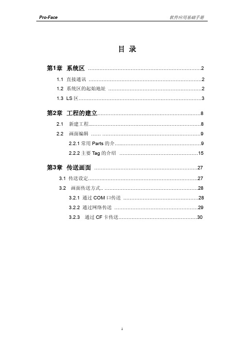
proface 软件应用基础手册
1
Pro-Face
第1章
系统区
软件应用基础手册
第 1.1 章
直接通讯
在直接通信中,GP 画面显示所需的数据由 GP 自动地发出请求并接收, 触摸键的操作输入由 GP 自动地送到 PLC。在 PLC 上,不需要为画面显示、 操作编写专门地程序。
第 1.2 章
系统区的起始地址
系统数据区是 GP 中固定的一部分存储区域,在 PLC 中需要开辟对应 的系统数据区域,进行对 GP 运行中各种控制参数的相互交换。
8
Pro-Face
第 2.2 章
画面的编辑
软件应用基础手册
按 ”SCREEN” 按 钮 , 即 课进入绘图板进行画面 的编辑
2.2.1 常用的 Parts 介绍
位开关(Bit Switch) 位开关是一种触摸开关,用于改变一个位地址的 ON/OFF 状态。 注意:在 GP 单元不与主机(PLC)连接时,带监视功能的位开关在 GP 单 元上不显示, 只有当 GP 与主机(PLC)连接正常后,才能被显示。
LS2042 ~ 保留
LS2047
仅用于 n:1(multi-link 连 接)
5
Pro-Face
◆公用继电器信息(LS2032)
软件应用基础手册
◆基本画面信息(LS2033)
◆保留(LS2034) 保留区域的值是不确定的,请不要使用这些区域。
z 1 秒二进制计数器(LS2035) GP 上电后,以 1 秒为单位进行计数。数据是二进制格式。
如何存取 LS 区
系统数据区的内容和范围
下表解释直接通讯时系统数据区每个地址的写入内容。
项目# 字地址
内容
位
解释
1
- 1、下载文档前请自行甄别文档内容的完整性,平台不提供额外的编辑、内容补充、找答案等附加服务。
- 2、"仅部分预览"的文档,不可在线预览部分如存在完整性等问题,可反馈申请退款(可完整预览的文档不适用该条件!)。
- 3、如文档侵犯您的权益,请联系客服反馈,我们会尽快为您处理(人工客服工作时间:9:00-18:30)。
執行DOPSoft,選擇【選項】 【數據代號表】,點選,選擇delta.csv
Step3. 輸入符號名稱test、位址為D23,設定完按下確定離開視窗。
執行DOPSoft,選擇【選項】 【數據代號表】,點選,選擇test.csv
2-2-8-5列印排版管理
執行列印排版管理前,請注意以下幾點:
✓
換畫面所指定的畫面不能是列印畫面。
✓
列印畫面不能是預設畫面。
✓
列印畫面不能是基底畫面。
✓
列印畫面不能是子畫面。
✓
列印畫面不能是螢幕保護畫面。
列印排版管理分為【列印全部畫面】、【列印自訂畫面】。
【列印全部畫面】代表使用者若將欲列印的4個畫面拖曳至右方的列印畫面中,則會將此4個畫面全部列印。
列印畫面亦可以列印歷史資料。
使用者可自行選擇欲列印的畫面且排版其順序或刪除不必要列印之畫面。
《圖2-2-8-7》列印排版管理畫面
【列印自訂畫面】則是使用者自行指定欲列印的畫面。
因此可設定其畫面讀取位址,列印的範圍之高度(Height)、寬度(Width)、列印範圍起點的X座標(Left)、列印範圍起點的Y座標(Top)。
此功能可與控制區列印旗標、輸出報表按鈕。
《圖2-2-8-8》列印自訂畫面
《表2-2-8-9》設定列印自訂畫面
2-2-8-6音效輸出設定
使用者可透過此音效輸出的方式告知現場操作者目前是否有錯誤發生。
音效輸出可針對音效檔案的Bit位址觸發來播放音效,並且可以搭配Word暫存器內數值指定不同的音效檔案來播放。
音效所支援的格式為MP3、WA V。
目前音效輸出設定所支援的機種只有B07E415、B07E515、B08E515、B10E615。
若所編輯的專案不是所支援的機種,是無法點選此項設定。
《圖2-2-8-9》音效輸出設定
音效輸出設定可分為三大項來說明:一、音效檔管理;二、控制清單;三、播放清單。
音效檔管理為加入音效檔、刪除音效檔、匯出音效檔與音效檔的存放位置等。
《圖2-2-8-10》音效輸出設定
控制清單為管理音效如何播放、結束與觸發。
《圖2-2-8-11》控制清單
播放清單為設定欲播放的音效檔與是透過Bit或Word讀取來播放。
《圖2-2-8-12》播放清單
以下將詳細說明【音效檔管理】、【控制清單】、【播放清單】。
若選擇結束模式為播完再停止,則音效檔會於播放完後才會停止。
進入【選項】→【音效輸出設定】→【音效檔管理】,點選加入音效檔圖示。
點選後,請選取欲加入的音效檔至音效檔清單。
設定完讀取位址後,接著設定其播放模式為【播放】、結束模式為【停止】與
選取Sound001音效檔案至播放清單。
請先將外部儲存裝置USB插入人機,並下載畫面資料至人機,觸發$100.0交替型按鈕,即可完成音效播出的動作。
請再一次於軟體編輯畫面建立一數值輸入元件,設定寫入記憶體位 進入【選項】→【音效輸出設定】→【播放清單】,點選【加入播放
加入播放項目後,設定讀取方式為Address,讀取位址為$200。
使用者可利用$200輸入所對應的音效檔清單內的編號。
請先將外部儲存裝置USB插入人機,接著下載畫面資料至人機。
先設定$200數值選擇音效後,再觸發$100.0交替型按鈕,即可完成音
2-2-8-7圖形庫
圖形庫是為了讓使用者可以更快速的將圖形應用於元件上,因此提供使用者可自行匯入非系統提供的圖形,還可做簡易的圖形處理,例如色彩對換、轉成256灰階、水平鏡像、垂直鏡像。
圖形庫提供【新增圖形庫】、【開啟安裝圖形庫】、【移除圖形庫】、【更新圖形庫內容】、【將圖形資料匯入】、【將圖形庫內容匯出至檔案】、【刪除】、【色彩對換】、【轉成256灰階】、【水平鏡像】、【垂直鏡像】。
新增圖形庫後,使用者可點選此按鈕將欲匯入的圖形資料匯入至圖形庫內。
匯入圖形資料後,亦可將圖形庫內容匯出,匯出的檔案是以.bmp為儲存格式。
2-2-8-8詞句庫
使用者可自行編輯某些常用到的詞句並存放於詞句庫中,如此一來,當元件上需要輸入文字時,即可直接從詞句庫中匯入先行編輯的字串,而不需要再重新鍵入。
因此,文字處理功能提供使用者可與詞句庫做連接,將已建立好的文字直接匯入至已選取的元件,如下圖所示。
《圖2-2-8-13》從詞句庫匯入文字
若使用者建立多個語系,亦可於詞句庫裡事先編輯好語系文字資料。
《圖2-2-8-14》多國語系詞句庫內容
欲刪除資料列時,請先點選欲刪除的資料,再按下刪除按鈕。
開啟文字檔後,詞句庫會將文字檔裡的資料匯入。
2-2-8-9環境設定
環境設定代表使用者可以設定與人機系統相關的環境參數,包括軟體語言介面顯示、下載模式等。
以下將一一介紹環境設定內的參數設定。