ABB智能照明定时器说明书
ABB 门磁 灯光开关机械器操作指南说明书
ABB-Welcome83330-50083330-515Switch actuator, door/light1Safety (3)2Intended use (3)3Environment (3)3.1ABB devices (3)4User Manual (3)5Operation (4)5.1Standard operation (4)6Technical data (5)7Mounting / Installation (6)7.1Requirements for the electrician (6)7.2General installation instructions (6)7.3Mounting (7)7.4Connection (7)1 SafetyWarningE lec tric voltage!Risk of death and fire due to electrical voltage of 230 V.– Work on the 230V supply system may only be performed by authorised electricians!– Disconnect the mains power supply prior to installation and/or disassembly!2 Intended useThe 83330-500 switch actuator is an integral part of the ABB-Welcome door communication system and operates exclusively with components from this system. The device must only be installed on mounting rails according to DIN EN 500022.EnvironmentC ons ider the protec tion of the environment!Used electric and electronic devices must not be disposed of with domestic waste.– The device contains valuable raw materials which can be recycled. Therefore, dispose of the device at the appropriate collecting depot.3.1A B B devic esAll packaging materials and devices from ABB bear the markings and test seals for proper disposal. Always dispose of the packaging material and electric devices and their components via the authorized collecting depots and disposal companies.ABB products meet the legal requirements, in particular the laws governing electronic and electrical devices and the REACH ordinance.(EU-Directive 2002/96/EG WEEE and 2002/95/EG RoHS)(EU-REACH ordinance and law for the implementation of the ordinance (EG) No.1907/2006)4 User ManualDetailed information for planning ABB-Welcome systems is contained in the user manual. Download at.ABB-Welcome Operation5 Operation5.1S tan dard operationFig. 1:ABB-Welcome Technical data 6 Technical dataDes ignation V alueOperating temperature (EN 50486) -5° C – +45° CStorage temperature -20°C – +70°CProtection IP 20Single-wire clamps 2 x 0.6 mm² – 2 x 1 mm²Fine-wire clamps 2 x 0.6 mm² – 2 x 0.75 mm²Volume Maximum 80 dBBus voltage 28 V- ±2 VDoor opener Maximum 3 ASize 4 TESwitch actuator, light:•Neon light 350 W•230 V Halogen lamp 300 W•Low-voltage halogen light with conventional350 VAtransformer•Low-voltage halogen light with electrical transformer 300 VA7 Mounting / InstallationWarningE lec tric voltage!Risk of death and fire due to electrical voltage of 230 V.– Low-voltage and 230 V cables must not be installed together in a flush-mounted socket!In case of a short-circuit there is the danger of a 230 V load on the low-voltage line.7.1R equirements for the elec tric ianWarningE lec tric voltage!Install the device only if you have the necessary electrical engineering knowledge and experience.•Incorrect installation endangers your life and that of the user of the electrical system.•Incorrect installation can cause serious damage to property, e.g. due to fire.The minimum necessary expert knowledge and requirements for the installation are as follows:•Apply the "five safety rules" (DIN VDE 0105, EN 50110):1. Disconnect from power;2. Secure against being re-connected;3. Ensure there is no voltage;4. Connect to earth;5. Cover or barricade adjacent live parts.•Use suitable personal protective clothing.•Use only suitable tools and measuring devices.•Check the type supply network (TN system, IT system, TT system) to secure the following power supply conditions (classic connection to ground, protective earthing, necessaryadditional measures, etc.).7.2G eneral ins tallation ins truc tions•Terminate all branches of the wiring system via a connected bus device (e.g., indoor station, outdoor station, system device).•Do not install the system controller directly next to the bell transformer and other power supplies (to avoid interference).•Do not install the wires of the system bus together with 230 V wires.•Do not use common cables for the connecting wires of the door openers and wires of the system bus. •Avoid bridges between different cable types.•Use only two wires for the system bus in a four-core or multi-core cable.•When looping, never install the incoming and outgoing bus inside the same cable.•Never install the internal and external bus inside the same cable.7.3MountingThe device 83330-500 must only be installed on mounting rails according to DIN EN 500022.7.4C onnec tionFig. 2:No. F unc tion1 •Connection for the system controller•When using several indoor stations: connection for the internal bus2 Depending on the operating mode selected.•Connection for a door opener•Connection for lightingABB-Welcome0073-1-7521 | | 22.02.2012A member of the ABB GroupBusch-Jaeger Elektro GmbH PO box58505 LüdenscheidFreisenbergstraße 2 58513 Lüdenscheid Germany ***************.comCentral sales service:Phone: +49 180 5 669900 Fax: +49 180 5 669909NoticeWe reserve the right to at all times make technical changes as well as changes to the contents of this document without prior notice. The detailed specifications agreed to at the time of ordering apply to all orders. ABB accepts no responsibility for possible errors or incompleteness in this document.We reserve all rights to this document and the topics and illustrations contained therein. The document and its contents, or extracts thereof, must not be reproduced, transmitted or reused by third parties without prior written consent by ABB.Copyright© 2012 Busch-Jaeger Elektro GmbH All rights reserved。
ABB说明书

基本操作及编程培训IRC5 机器人系统IRC5 Basic Operation and Programming Training上海ABB工程有限公司 ABB Engineering (Shanghai) Ltd. 教材编号:S5-100 2006年03月IRC5 Basic Operation And Programming Training 基本操作及编程培训2IRC5 Basic Operation And Programming Training 基本操作及编程培训Content 目录1 2 3 Overview 介绍 ...................................................................................................................................5 Safety and environment protection 系统安全及环境保护 ............................................................6 General 系统概述 ..............................................................................................................................73.1 3.2 IRC5 System IRC5系统 ............................................................................................................................. 7 Consist of the system 系统组成................................................................................................................. 8 Buttons on the Control module 控制单元柜按键.................................................................................. 10 Buttons on the Drive module 驱动单元柜按钮 ...................................................................................... 12 Start the controller 启动 ........................................................................................................................... 134Start the controller 启动 .................................................................................................................104.1 4.2 4.35 6Shut down the controller 关机 .......................................................................................................14 FlexPendant 示教器 ........................................................................................................................156.1 6.2 6.3 6.4 6.5 6.6 6.7 6.8 Buttons on the FlexPendant 示教器按键 ................................................................................................. 16 The ABB Menu ABB菜单 ..................................................................................................................... 18 Close Button 关闭键 .............................................................................................................................. 19 Task Bar 任务栏 .................................................................................................................................... 19 Status Bar 状态栏 .................................................................................................................................... 20 The Quickset menu 快捷菜单.................................................................................................................. 20 Soft keyboard 软键盘 ............................................................................................................................. 21 Scrolling and Zooming 磙动与缩放 ...................................................................................................... 217 8 9Jogging the robot using the Joystick 使用操纵摇杆移动机器人 ................................................23 Precise positioning 精确定点..........................................................................................................298.1 9.1 9.2 Incremental movement 步进运动 ............................................................................................................ 29 Load an existing program 加载一个已存在的程序 ................................................................................ 31 Start and test a program in Manual mode手动测试程序 ......................................................................... 33Load a program 加载程序 .............................................................................................................3110 Stopping the program 停止程序 ....................................................................................................38 11 Running a program in Automatic mode自动运行程序 ...............................................................39 12 Rapid Programming Rapid编程 ....................................................................................................4112.1 12.2 12.3 12.4 12.5 12.6 13.1 13.2 13.3 13.4 Consist of the program 程序的组成 ........................................................................................................ 41 Basic Movement Instructions 基本运动指令 .......................................................................................... 42 Input/Output Instructions 输入/输出指令 ............................................................................................... 45 Communication Instructions 通讯指令 ................................................................................................... 46 Program Fflow Control Instructions 程序流程指令 ................................................................................ 46 Other Common Instructions 其他常用指令 ............................................................................................ 47 Modify positions (tune with motions) 修改位置点 ................................................................................. 48 Editing instruction arguments 编辑指令变量.......................................................................................... 49 Adding instructions 增加指令 ................................................................................................................. 52 Programming a delay 编辑延迟 .............................................................................................................. 5413 Editing a program 编辑程序 ..........................................................................................................483IRC5 Basic Operation And Programming Training 基本操作及编程培训14 I/O Signals 输入/输出信号..............................................................................................................5714.1 15.1 15.2 15.3 15.4 15.5 15.6 15.7 15.8 15.9 Programming an I/O instruction 编辑一条输入/输出指令 ..................................................................... 57 What is a log? 什么是纪录? .................................................................................................................. 60 What is an event? 什么是事件? ............................................................................................................ 60 What is an event message? 什么是事件信息? ...................................................................................... 60 What is an information message? 什么是通知信息? ............................................................................ 61 What is a warning? 什么是警告? .......................................................................................................... 61 What is an error? 什么是错误? ............................................................................................................. 61 What is "acknowledge"? 什么是确认 ?................................................................................................. 61 Open and close the event log 打开关闭事件纪录 ................................................................................... 61 View a message 查看信息 ....................................................................................................................... 6215 Event log 事件纪录..........................................................................................................................6016 Emergency stop 紧急停止 ..............................................................................................................64 17 Operational modes 运行模式 .........................................................................................................6517.1 17.2 17.3 18.1 18.2 18.3 What is the manual mode? 什么是手动模式? ...................................................................................... 65 Manual mode 100% (Option, testing mode)手动全速(选项,测试模式) ......................................... 65 Automatic mode (production mode) 自动模式(生产模式) ................................................................ 66 Manipulator 机器人本体 ......................................................................................................................... 69 Controller 机器人控制柜 ........................................................................................................................ 69 Other 其它................................................................................................................................................ 6918 Maintenance 机器人保养检查表 ...................................................................................................69 在没有声明的情况下,文件中的信息会发生变化。
ABB智能照明控制方案

灯光在感应器触发关闭之前2分钟会以闪烁灯光的方式给予提示
现代办公楼重点区域解决方案
时间控制
动静感应
日光采集
亮度管理
集成控制
>日光采集:将靠近窗台的区域划分为日光采集区,在工作平面上方天花安装闭环照度感应器,系统根据照度感应器获取
的环境照度值自动调整电气照明的亮度,使办公室始终保持恒定的照度。
节能
现代办公楼重点区域解决方案
总能耗 100%
最大能耗
50%
0%
时间
谢谢!
• 智能灯光控制系统 • 电子地图前台管理
总裁、经理办公室 • 智能灯光集中控制
办公区
• 智能照明控制
安保及中央控制室
地下停车场
现代办公楼重点区域解决方案
01/办公区(Office)
>传统办公区控制 VS ABB智能系统控制
控制对象 传统控制
1. 2. 3. 4. 单独分区域控制, 不能实现场景控制, 手动控制, 控制点多而且繁琐
0-10V
• LED射灯,灯带 • 荧光灯
DMX
• RGB 射灯 • RGB软灯
DALI
• LED射灯,灯带 • 荧光灯
P楼重点区域解决方案
时间控制
动静感应
日光采集
亮度管理
集成控制
>集成控制:包括窗帘、空调HVAC、能源管理、办公室音视频系统(如背景音乐系统)等
时间控制
动静感应
日光采集
亮度管理
集成控制
>亮度管理:通过办公室的智能按键面板,可以调用不一样的灯光模式,比如:上班模式,休息模式,下班模式。
各种模式下的灯光亮度水平不一样,为员工营造更舒适的办公环境。调光系统可以控制多种照明光源,比如:LED射 灯或灯带、荧光灯、冷阴极管等:
ABB 电灯具安装说明书

Thank you for choosing ABB productPlease read this document thoroughly before commencing installation and retain for future reference. Contact ABB customer service in Australia on 1800 60 20 20 if you need any assistance. The installation instructions were correct at the time of print. To reflect changes in technology and Australian standards; ABB reserves the right to amend the instructionswithout notice. Updated document can be found on the Stanilite website.Safety warningIn Australia and New Zealand, only licensed electricians are permitted by law to work with 240 volt electrical installations.Do not attempt to install or connect this product unless you are a licensed electrician.Turn off and isolate the electrical supply before connecting this fitting to the building wires.Do not touch the terminals of the terminal block when the light fitting is energised.The only user-serviceable part is the battery pack. For safety, remove exit from the ceiling bracket. Do not attempt to service other parts of the fitting as this will void the warranty.As the installer, it is your responsibility to ensure compliance with all relevant building and safety codes, (ie: AS/NZS 3000, AS/NZS 2293). Refer toThis document covers What’s inside the box Safety warningMain chassis and diffuserassembly Installation instructions Ceiling bracket assembly Removal instructions Pictograph insert pack Testing precautions Hole plug set (6 pieces)Troubleshooting guideInstallation manual Warranty informationImportant to note:• This product is designed for indoor use only.the applicable standards for data and mains cabling installation procedures and requirements.Nexus LX (data cable system)The Nexus range of emergency light fittings are designed to be connected together into a special communication network over a level 4 (or higher) high speed, single twisted pair data cable. The Nexus user and technical guide describes all you need to know to successfully install a Nexus project. Ask for it from your superviser, from your employer or from your nearest ABB product supplier. The network cabling of the building must be installed as per the procedure detailed in the Nexus user and technical guide. No mains or mains carrying cables are to be connected to the data terminals or cables.Nexus RF (wireless system)The Nexus RF range of light fittings are designed to communicate via a proprietary RF network, however the electrical installation of the fittings is identical to that of a standard non-monitored fitting.Doc no. 29-01100_16—ABB Australia Pty Limited For enquiriesABB contact centre: 1800 60 20 20E-mail:************************.au© Copyright 2020 ABB. All rights reserved.Construction sitesContinuously switching off the mains power supply that is connected to emergency light fittings during the construction phase of aninstallation will cause these fittings to discharge and charge their batteries many times over a short period; this can shorten life of the battery. ABB does not recommend such practices and may not honour the warranty on batteries when they are subjected to such harsh operatingconditions. Emergency light fittings are designed to be discharge tested once every 6 months as per AS/NZS 2293.2, subjecting the product to repeated discharge or charge cycles is regarded as an abuse of the fittings.LED flash patterns :LED flash patterns are assembled in time slots - the each slot time is 250ms.In the table on right GG-- represents the green led on for two slots (ie 500ms), off for a further two slots - then repeated. The result is the green led flashing on and off. TheIdentification pattern YYY-Y-Y-Y-Y-Y-- uses al the available slots. Y is yellow - which is both green and red on at the same time. R indicates the red LED on continuously. Testing precautionsOnce the fitting is permanently connected to the mains supply, a commissioning discharge test as required in AS/NZS 2293.2 must be carried out. You will need to allow 24 hours for the battery to fully charge prior to conducting this test,presently (at the time of writing), the standard requires that fittings operate in emergency mode for a period not less than 2 hours for their commissioning test and for not less than 90 minutes thereafter (it is required that 6 monthly discharge tests be carried out). You will need to keep the records for the commissioning test and enter them into the building emergency services logbook or via other recording methods as allowed by AS/NZS 2293.2.Troubleshooting guideNo.Fault Possible causes1LED light source and indicating LED not lit AC supply not connected; or AC supply turned off2LED light source is lit but indicating LED not lit Battery not connected or faulty 3LED light source does not switch to emergency mode when the test button is pressedTest switch damaged; orBattery not connected or faulty4LED light source works momentarily on emergency when the test button is pressedBattery not yet charged (allow up to 24 hours)3. The fitting will automatically switch intoemergency mode because it has beenremoved from the power supply. It will stay on emergency until such time as the battery cut-off threshold is reached or it is reconnected back onto the power supply, whichever happens first. 4. When the fitting is reconnected to the supply,it will need time to recharge its battery before it will be capable of a full length discharge again. The ability of the fitting to operate on emergency is determined by the age, charge level, operating temperature conditions and environmental circumstances of the battery in the fitting.9A K K 106713A 9570 - E - S e p 2020—I N S TA LL ATI O N M A N UA LStanilite®Exit LED Quickfit®_V2Emergency, Nexus® LX, Nexus® RFStateLED patternManis offna Configuration error GG--Hardware fault G-R-Button pressed G Battery not charging off Under test RR--No network G-R-R--Identification YY-Y-Y-Y-Y-Y-Y--Uncommission G-R-R-R Unit OKRActive NeutralEarthQuickfit mounting bracketInsert here to removeTerminalblock For ceiling mount; screw through holes labelled ‘A’For wall mount; screw through holes labelled ‘B’ via slot ‘C’To fit fitting to mounting bracket insert at 1 then 2Cable entryholesFigure 2: Quickfit insertion diagram and internal viewFigure 1: Quickfit terminal block connectionTerminal block Quickfit mounting bracketCable entry holeInsert here to removeFigure 3: Quickfit vertical wall mountingInstallation instructions1. Take the mounting bracket and whilst holding it into place against the ceiling or wall, use a pencilto mark the position of the screw holes (at A or B in figure 2) and cable entry position through the bracket onto the ceiling or wall as appropriate. Make sure to allow at least 50mm of free space to the right hand side of the final location of the fitting to allow for the sliding function of attaching the fitting to the mounting bracket. If need be, turn the bracket around and swap the diffuser with the back plate to permit room for inserting and removing the fitting from the mounting bracket. Orient the bracket in such a way as to make the LED and push button readily visible and accessible when the fitting is installed.2. Remove the bracket to reveal the pencil marks and if the cabling is to be concealed, drill a 20mmhole for the cable entry prior to installing the bracket. Make sure the mounting screw locations are into solid material and strong enough to support the weight of the complete fitting, (approx 2kg: build-up, strengthen or support the mounting material if necessary) and attach the bracket. Because of the wide variety of building construction materials and the wide variety of screw fasteners appropriate to each type, mounting screws are not provided with the fitting. If appropriate and safe, drill and use your own fixing holes in the mounting bracket to suit the individual installation location and structural support needs of the fitting, taking care not to obstruct the fitting slide entry.3. Run the cables in the ceiling or wall space as appropriate or surface mounted in conduit andthrough the cable hole into the bracket. Strip, connect and terminate the cables as indicated in figure 1. Ensure that the double insulation of the cable/s passes completely into the terminal block enclosure so that no single insulation is exposed when the cover plate is in place. The hole plug set includes a suitable bush to mechanically protect the cable as it passes through the opening in the mounting bracket. Likewise, the single insulation of the conductors should run right up to the metal edge of the terminals leaving no bare conductors outside of the terminals. Be careful with multi-strand conductors that all of the strands are twisted together before insertion into theterminal. Any stray strands that inadvertently come into contact with their neighbouring terminal of the metal frame of the fitting will cause undesirable results when the fitting is powered.Removal instructions1. Gently insert a small screwdriver into the slot(at ‘D’ in figure 2) on the front of the bracket towards the right hand end of the fitting, to ease the locking tab into the fitting and away from the bracket.2. The fitting is then free to slide to the rightalong the bracket for about 50mm, at which time the slots line up and it can be lowered away from the bracket, allowing the two to separate.4. For Nexus LX product; refer to data connections section.5. Attach the fitting to the mounting bracket by aligning the top left hand end of the fitting (the endwithout the protruding electrical connecting metal lugs) with the large cut-away slot towards the left hand end of the bracket. Slip the left hand end of the fitting up into the slot in the left hand end of the bracket (step 1 in figure 2) and hold the fitting horizontal to and parallel with the bracket. It should be approximately 50mm to the right of its final destination. Simply slide the fitting (step 2 in figure 2) 50mm to the left along and into the bracket to engage the connections and the locking tab. Once in place, the fitting cannot be removed from the bracket without the use of a tool (a small screwdriver) to push in the locking tab at ‘D’ in figure 2. Ensure the correct pictograph inserts have been attached to the diffuser assembly.6. Once powered up, the normal AC LED light source will energise and remain lit until the powersupply fails. The emergency function of the light fitting will only operate when the normal lighting power supply fails or when somebody presses the manual test button located on the front of the fitting. Red LED indicates that the power is connected and the battery is charging.• For Maintained exit, wire link between SA and USA must be in place. Connect incoming unswitched active, neutral and earth to terminal marked USA, N and E respectively.• For Non-maintained exit, remove the wire link between SA and USA refer (Fig 1). Connectincoming unswitched active, neutral and earth to terminal marked USA, N and E respectively.7. Check the operation of the fitting to ensure that the installation was successful. When poweredup, allow a few minutes to give the battery a small charge, then press the manual test button located at the front face of the fitting. Hold the test button in for a few seconds and observe the operation of the LED light source switching from mains to the emergency mode. If the LED light source on emergency mode works momentarily, that’s okay. Try again in a few more minutesbecause if the battery was completely discharged, it may take a little time to charge up enough to operate even momentarily. After this time, press the test button again, and if the LED light source does not work at all, check the supply, the connections and the troubleshooting guide at the end of this document.Important: If installing this product into an early version ceiling bracket, first remove the 2 hole blanking plugs on the front face of the bracket and replace with the short hole plugs provided with the product.Vertical wall mounting1. If mounting exit vertically on side wall, youmust allow approximate 50mm free space above the ceiling bracket in order to slide the exit (step 2) into ceiling bracket.2. The exit must only be installed as per figure 3,that is, with the terminal block at the top. This is to ensure that the exit is securely held and cannot inadvertently slide out of the bracket.Data connectionsNexus LX fitting• The same colour wire from each data cables connects to the terminal marked +.• The other colour wire from each of the data cables connects to the terminal marked -.• When connected, replace the terminal block cover so that it clicks and locks into place.• No mains or mains carrying cables are to be connected to the data terminals or cables.Important: 24 hours is required to allow the fitting battery to reach full capacity, ie: prior to a discharge test. As the installer, it is your responsibility to conduct the initial discharge testing of the installed fitting. Refer to AS/NZS 2293.。
ABB智能照明触摸屏操作手册

2.
(1)将开关面板上方的防误操作开关按下,当LID指示灯点亮后方可对面板进行操作。
(2)以五联面板为例,第一联低等照度,第二联中等照度,第三联开启一半,第四联开启前段部分。第五联全开/全关。(左关/右开)
点击车间灯光全开,在弹出对话框中点击ON开启按钮,点击OK操作完毕(如图2-6)。
图2-6
(2)车间灯光全关操作步骤
在触摸屏主菜单中点击车间整体控制,输入密码1111,按OK进入车间整体控制菜单(如图2-5),点击车间灯光全关,在弹出对话框中点击OFF!!关闭按钮,点击OK操作完毕。
(3)
在触摸屏主菜单中点击绿色通道照明,输入密码1111,按OK进入绿色通道菜单(如图2-7),点击绿色通道照明按钮,在弹出对话框中进行相应的开启和关闭操作。
3MMC/SD卡读卡机
4. 基本参数
型号6136/100C
功能数量(控制设备数量)100
场景数量32场景
20组设备/场景
定时数量20通道
10个时间/通道
报警/故障信息数量50
IR通道10
模拟有人在家有
内置室内温控器有
显示320 x 240像素256彩色
消息功能有
信息功能有
警报时钟/定时器功能有
读卡机SDMMC
ABB触摸屏操作手册
一
1.
工作于230V,应由受过培训的专业人员操作!安装和拆卸前须断开主要电源!
屏幕表面的刮痕会影响触摸屏的操作。
切勿用坚硬或锋利的物体触摸屏幕,否则会损伤屏幕的表面。
不要将清洁剂和水直接喷洒在触摸屏表面。
用柔软的布轻轻擦拭屏幕表面。
【VIP专享】ABB使用说明书最新版

前言衷心感谢您使用“华振”牌智能变频供水设备,我们将为您提供优质的产品和星级的售后服务。
我公司吸取行业内智能变频供水设备的技术精髓,集长期从事水泵行业和智能变频供水设备的设计经验,研制开发的ZBH第三代、第四代、第五代、第六代智能变频供水设备,已广泛运于高层建筑、住宅楼、商住楼、新老小区降耗节能改造、高级宾馆、医院、学校、工矿企业的生产生活用水等,是一种节能型,现代化,智能化的变频供水设备。
本使用说明书向您详细介绍了“华振”牌系列智能变频供水设备的产品说明、技术说明、操作、故障处理,保养维护等各方面内容。
为了更好的使用智能变频供水设备,请您在操作前仔细阅读本说明书,这将会:●帮助您了解智能变频供水设备的结构及性能特点。
●避免由于操作不当而引起的设备故障。
●提高设备的使用寿命。
●增强设备使用的可靠性。
值得注意的是,本说明书的资料及图形在出版时是正确的,但我公司产品的结构和性能总在不断地改进和完善,本说明书的相关内容可能有变化,恕不一一通知,敬请谅解。
感谢您对“华振”的信任,衷心地祝愿您在事业中大展宏图,取得辉煌成就。
成都华振供水设备有限公司- 1 -))1 MΩ电阻与机壳连接用于模拟输入电位器的给定电压输出.10 V±2%))1 MΩ电阻与机壳连接频率。
0…20 mA ( 数字输入6,可编程。
默认Ω。
数字输入最大电压一般显示性能软键功能每个软键上方的文字描述的是当前软键功能的含义。
显示对比度同时按住 MENU (菜单)键和 UP (向上)或DOWN (向下)可以改变显示对比- 5 -顶行液晶屏的顶行显示变频器的基本的状态信息。
• LOC (本地) - 表示变频器处于本地控制,即控制命令来自控制盘。
• REM (远程) - 表示变频器处于远程控制, 例如 I/O (X1) 或现场总线。
• - 显示变频器和电机的旋转状态:4、应用宏的选择 中崛供水设备应用宏选择,用于泵的循环软起控制中,在ABB 变频器设置中9902的值为15(SPFC 控制).注意! 参数2108 START INHIBIT (禁止起动)必须保持为默认设置0 (OFF)。
ABB照明功能说明
2.1智能照明控制功能说明:开关驱动器控制灯光开关,调光驱动器实现白炽灯、卤素灯、低压卤素灯调光,荧光灯调光驱动器实现荧光灯调光。
智能面板或红外遥控面板进行灯光的开关和亮度调节控制。
光照度感应模块进行恒照度控制。
通过移动感应模块实现自动感应控制。
实时反馈灯光开闭状态和调光亮度。
支持手动、遥控、自动控制、情景模式、远程联动控制等多种控制模式。
2.2智能卷帘控制功能说明:窗帘驱动器实现百叶窗、电动窗帘、户外遮阳帘、卷帘门、电动窗、电动投影幕的控制。
支持百叶窗自动调角和升降。
支持24V直流电机控制和230V交流电机控制。
结合光照度感应模块进行百叶窗的自动调角控制,保证室内舒适光照度。
通过气象传感器探知恶劣天气情况,自动收起户外遮阳卷帘。
支持手动、遥控、自动控制、情景模式、远程联动控制等多种控制模式。
2.3暖通空调控制功能说明:通过风机盘管控制器实现盘管型空调控制;通过KNX空调网关实现家用VRV空调整体智能控制;通过红外发射模块实现家用普通空调控制。
通过电热阀驱动器控制地暖系统的分水阀,实现地暖温度调节。
通过开关驱动器实现新风系统的启停控制。
通过智能无线温控面板实现盘管式空调、VRV空调、家用普通空调及地暖系统的温度调节。
通过无线门窗磁感应器监视门窗状态,当门窗打开一定时间后自动关闭空调系统,减少能源耗费。
支持手动、遥控、自动控制、情景模式、远程联动控制多种控制模式。
2.4家居安防系统功能说明:用户外出时,可通过红外探测、视频监控等功能,实现异常入侵的实时监控,及时处理异常情况,并发出声光告警。
借助红外感应、视频监视、烟雾探测、煤气探测、门窗探测等功能实现家居内部安全监视,做到出现问题及时报警。
智能家居安防系统可对非法入侵、煤气泄漏、火灾等紧急情况及时警报,一旦发生警报,控制终端将与声控系统联动发出告警声,并自动拨打和发送短信到住户设定的电话或手机以通知住户,通过语音提示告知住户家中何处发生何种警报。
ABB CT范围电子计时器产品说明书

2C D C 255 056 F 0006Electronic timers CT rangeNE W!21S V C 110 000 F 05071S V C 110 000 F 0506Connecting screws in M3 (Pozidrive 1)Easy actuation of thec onnecting combination screws, with pozidrive, pan- or cross-head screwdriver.Remote p otentiometerconnectionThe CT -S range offers thep ossibility of connecting a r emote potentiometer for the fi ne adjustment of the time delay. When an externalp otentiometer is connected, the internal, frontface potentiometer is disabled.or many years, ABB’s CT range of electronic timers has been used in applications world-wide and has proven its excellent functionality in daily use, even under harshest environmentalc onditions. T hree ranges of electronic timers provide timing functions for all applications: T he highly sophisticated CT-S range is ideallys uitable for universal use. The CT-D range with modular design in only 17.5 mm wide enclosures.And the CT-E range offers an excellent price/performance ratio and is an ideal s olution for serial applications. Make use of ABB’s e xcellent competence in i ndustry e lectronics.FElectronic timers CT rangeCT-D rangeNE W : 2c /o c o n t a c t s32C D C 255 056 F 00062C D C 253 065 F 00062C D C 253 010 F 00032C D C 253 011 F 00032C D C 253 064 F 00062C D C 253 062 F 00062C D C 253 132 F 0006Direct reading scalesDirect setting of the time delay without any additionalc alculation provides accurate time delay adjustment.SafetyThe “real distance” is hidden.Our products‘ air and creepage distances exceed international standards, and substantiallyi ncrease the safety of these products.LEDs for status indicationAll actual operational states are displayed by frontface LEDs, thus simplifying commissioning and troubleshooting.Sealable transparentc over Protection against u nauthorized changes of time and t hreshold values. Available as ana ccessory.Integrated marker labelsIntegrated markers allow the product to be marked quickly and simply. No additional marking labels are required (CT -S range).Time range preselection and fi ne adjustmentDirect assignment of the pre-selected time range to the fi ne adjustment potentiometer scale by multicolor scales.42C D C 256 059 F 00062C D C 253 022 F 0004multifunctionalOperating controls➀ LEDs for status indication U - green LED:c ontrol supply voltage applied timingR - yellow LED:output relay energized ➁ Time range adjustment➂ Fine adjustment of the time delay ➃ Preselection of the timing functionElectronic timers CT -D range: The modular timerssingle-functional➂➁ ➀➂➁ ➃NE W : 2c /o c o n t a c t s52C D C 255 058 F 00062C D C 252 047 F 00062C D C 252 048 F 00062C D C 253 066 F 00062C D C 253 132 F 00062C D C 253 033 F 00042C D C 253 021 F 000417.5 mm*partly pendingModular – CT -D rangeDirect reading scalesDirect setting of the time delay without anyadditional calculation provides accurate time delay adjustment.LEDs for status indicationAll actual operational states are displayed byfrontface LEDs, thus simplifying commission-ing and fault troubleshooting.Connecting terminalsWide terminal spacing allows connection of wires:– 2 x 1.5 mm² (2 x 16 AWG) with wire end ferrules or– 2 x 2.5 mm² (2 x 14 AWG) without ferrules.Width 17.5 mmWith their width of 17.5 mm, the CT -D range t imers are ideally suited for i nstallation in distribution p anels.Switching currentsThe CT -D range timers allow an output load of up to 6 A on devices with 1 c/o contact and up to 5 A on devices with 2 c/o contacts.Control input: Voltage-r elated triggering,non-polarized, capable ofs witching a parallel load.1S V C 110 000 F 05031S V C 110 000 F 0500➀➁ ➂➃6multifunctional Operating controls➀ LEDs for status indication U – green LED:control supply voltage applied R – red LED:output relay energized ➁ Time range adjustment➂ Fine adjustment of the time delay ➃ Preselection of the timing functionElectronic timers CT -E range: The economic timerssingle-functional2C D C 255 011 F 00051S V C 110 000 F 05081S V C 110 000 F 050672C D C 255 011 F 0005Economy – CT -E rangeConnecting screws in M3(Pozidrive 1)Easy and fast tightening and release of the connecting screws with pozidrive, pan- or crosshead screwdriver.Direct reading scalesDirect setting of the time delay without any additional calculation provides accurate time delay adjustment.LEDs for status indicationAll actual operational states are displayed by frontface LEDs, thus simplifyingc ommissioning and troubleshooting.82C D C 256 060 F 00062C D C 256 061 F 0006➄➁ ➂ ➀➃Electronic timers CT -S range: The high-end timersmultifunctional Operating controls➀ LEDs for status indication U/T – green LED:control supply voltage applied timingR/R1/R2 – yellow LED:1. /2. output relay energized ➁ Time range adjustment➂Fine adjustment of the time delay➃ Preselection of the timing function ➄ Set the 2nd c/o contact as an instantaneous contactsingle-functional92C D C 255 057 F 00061S V C 110 000 F 05072C D C 253 010 F 00032C D C 253 063 F 00062C D C 253 062 F 0006 High end – CT -S rangeIndication of operational statesAll actual operational states are displayed by front-face LEDs, thus simplifyingc ommissioning and troubleshooting.Double-chamber cage connectingt erminals Double-chamber cage connecting terminals provide connection of wires up to 2 x 2.5 mm 2(2 x 14 AWG), rigid or fi ne-strand, with orwithout wire end ferrules. Potential distribution does not require additional terminals.Connection of remote p otentiometersAn external potentiometer can be connected to the CT -S devices to make fi ne adjustments to the time ranges. The internal potentiometer switches off automatically when an external one is connected.Control input with volt-free 3) or voltage-related 4)t riggering 1)The new CT -S range offers two types of devices:one with volt-free and one with voltage-related triggering.The control inputs of the devices with voltage-related triggering are capable of switching parallel load and are not polarized. They can be powered either by the control supply voltage applied to A1 or by another voltage out of the rated control supply voltage range.NE W!1) selected devices 2) pending3) volt-free = dry/fl oating4) voltage-related = wet/non-fl oatingSelection guides and order references for electronic timers pe* with gold contactsControl input with voltage-related (wet/non-fl oating) triggeringControl input with volt-free (dry/fl oating) triggering Accessories: Sealable cover in 22,5 mm width: 1SVR 430 005 R 0100 Product Diameter Protection Resistance Ordercode Remote potentiometer 30.5 mm IP65 50 kΩ1SVR 700 800 R1000 Remote potentiometer 22.5 mm IP65 50 kΩ1SVR 701 800 R1000 Remote potentiometer 10.5 mm IP65 50 kΩ1SVR 214 017 R0900 EW!10CT-E range1) Functions: ON-delay, OFF-delay, impulse-ON, fl asher starting with ON or OFF, pulse shaper Control input with voltage-related (wet/non-fl oating) triggering2) Non-polarized, not capable of switching a parallel load11/12CT -D range, CT -E range, CT -S rangeCT -E range, solid state output1) contactless, function and time range selection via external jumpers 2) Functions: ON-delay (AC/DC), Impulse-ON (AC only), Flasher starting with ON (AC only), Flasher starting with OFF (AC only)1) 20...100 ms in 10 ms increments13Conversion table CT-S range 1SVR 430 ... -> 1SVR 630 ... CT-S rangeType old Order code old Type new /alternative Order code new / a lternativeMultifunctional timersCT-MFS1SVR 430 010 R0200CT-MVS.21CT-MFS.211SVR 630 010 R0200 1SVR 630 010 R0200CT-MVS1SVR 430 023 R0200CT-MVS.221SVR 630 020 R3300CT-MBS1SVR 430 010 R1200CT-MVS.22CT-MBS.221SVR 630 020 R3300 1SVR 630 010 R3200CT-MBS1SVR 430 012 R0200CT-MVS.22CT-MBS.221SVR 630 020 R3300 1SVR 630 010 R3200CT-MBS1SVR 430 011 R2200CT-MVS.231SVR 630 021 R2300CT-MBS1SVR 430 010 R1100CT-MVS.12CT-MBS.221SVR 630 020 R3100 1SVR 630 010 R3200CT-MBS1SVR 430 013 R0100CT-MVS.12CT-MBS.221SVR 630 020 R3100 1SVR 630 010 R3200CT-MBS1SVR 430 011 R2100CT-MVS.231SVR 630 021 R2300ON-delay timersCT-ERS1SVR 430 100 R1100CT-ERS.211SVR 630 100 R0300 CT-ERS1SVR 430 102 R0100CT-ERS.121SVR 630 100 R3100 CT-ERS1SVR 430 101 R2100CT-MVS.231SVR 630 021 R2300CT-ERS1SVR 430 103 R0100CT-MVS.21CT-MFS.211SVR 630 010 R0200 1SVR 630 010 R0200CT-ERS1SVR 430 100 R1200CT-ERS.211SVR 630 100 R0300 CT-ERS1SVR 430 103 R0200CT-ERS.221SVR 630 100 R3300 CT-ERS1SVR 430 101 R2200CT-MVS.231SVR 630 021 R2300ROFF-delay timersCT-AHS1SVR 430 113 R0100CT-APS.12CT-AHS.221SVR 630 180 R3100 1SVR 630 110 R3300CT-AHS1SVR 430 113 R0200CT-APS.22CT-AHS.221SVR 630 180 R3300 1SVR 630 110 R3300CT-APS1SVR 430 183 R0300CT-APS.221SVR 630 180 R3300 CT-ARS1SVR 430 120 R0100CT-ARS.221SVR 630 120 R3300 CT-ARS1SVR 430 120 R0300CT-ARS.121SVR 630 120 R3100 CT-VBS1SVR 430 261 R6000CT-VBS.171SVR 430 261 R6000 CT-VBS1SVR 430 261 R5000CT-VBS.181SVR 430 261 R5000ON- and OFF-delay timersCT-EAS1SVR 430 173 R0100CT-MXS.221SVR 630 030 R3300 CT-EAS1SVR 430 173 R0200CT-MXS.221SVR 630 030 R3300 CT-EVS1SVR 430 193 R0100CT-MXS.221SVR 630 030 R3300Type old Order code old Type new /alternativeOrder code new /a lternative Impulse-ON relaysCT-VWS1SVR 430 132 R0100CT-WBS.221SVR 630 040 R3300 CT-VWS1SVR 430 133 R0200CT-WBS.221SVR 630 040 R3300 Impulse-OFF relaysCT-AWS1SVR 430 143 R0100CT-MVS.121SVR 630 020 R3100 CT-AWS1SVR 430 143 R0200CT-MVS.121SVR 630 020 R3100 FlasherCT-EBS1SVR 430 152 R0100CT-WBS.221SVR 630 040 R3300 CT-EBS1SVR 430 153 R0200CT-WBS.221SVR 630 040 R3300 Pulse generatorsCT-TGS1SVR 430 163 R0100CT-MXS.221SVR 630 030 R3300 CT-PGS1SVR 430 253 R0100CT-MXS.221SVR 630 030 R3300 Star-delta change-over timerCT-YDAV1SVR 430 203 R0200CT-SDS.221SVR 630 210 R3300 CT-YDAV1SVR 430 201 R2300CT-SDS.231SVR 630 211 R2300 CT-YDEW1SVR 430 213 R0200CT-SDS.221SVR 630 210 R3300 Switching relaysCT-IRS1SVR 430 220 R9100CT-IRS.161SVR 430 220 R9100 CT-IRS1SVR 430 220 R8100not replaced-CT-IRS1SVR 430 221 R7100CT-IRS.141SVR 430 221 R7100 CT-IRS1SVR 430 220 R9300CT-IRS.261SVR 430 220 R9300 CT-IRS1SVR 430 220 R8300not replaced-CT-IRS1SVR 430 221 R7300CT-IRS.241SVR 430 221 R7300 CT-IRS1SVR 430 230 R9300CT-IRS.261SVR 430 220 R9300 CT-IRS1SVR 430 231 R7300CT-IRS.241SVR 430 231 R7300 CT-IRS1SVR 430 220 R9400CT-IRS.361SVR 430 220 R9400 CT-IRS1SVR 430 220 R8400not replaced-CT-IRS1SVR 430 221 R1400CT-IRS.351SVR 430 221 R1400D r u c k s c h r i f t -N r . 2C D C 110 003 B 0203 (04/06) P r i n t e d i n t h e F e d e r a l R e p u b l i c o f G e r m a n yABB STOTZ-KONTAKT GmbHPostfach 10 16 80, 69006 Heidelberg Eppelheimer Straße 82, 69123 Heidelberg GERMANY/lowvoltage –> Control Products –> Electronic Relays。
ABB电子计时器 CT 系列说明书

Electronic timers CT range2 2CDC111110B0203For many years, ABB’s CT range electronic timers has been used in applications worldwide and has proven its excellent functionality in daily use even under the toughest conditions. Three ranges of electronic timers provide timing functions for all applications.CT-DThe CT-D range with MDRC design (modular DIN rail compo-nents) in an enclosure with a width of only 17.5 mm fits into all domestic installation and distribution panels.CT-EThe CT-E range offers an excellent price/performance ratio and is an ideal solution for serial applications.ABB electronic timers CT rangeCT-SThe highly sophisticated CT-S range in ABB’s new S-range enclosure offers two different types of connection terminals and is ideally suited for universal use.AccessoriesThe CT-S range offers the possibility of using accessories such as a remote potentiometer to adjust the time delay or a sealable transparent cover to protect against unauthorizedchanges in time and threshold values.General news and benefitsThe CT range includes 103 electronic timers and switching relays with 16 different functions. The electronic timers are divided into three ranges with their individual benefits. A lot of different connection terminals such as screw, chamber, double-chamber cage and push-in connection terminals are available. Furthermore, relay outputs and solid-state outputs are also available.2CDC111110B0203 3The modular CT-D range of electronic timersThe CT-D range represents a link between industry and the installation types. For maximum flexibility in operation, 10 single-function as well as 2 multifunction devices with 7 timing functions are available. The devices offer 4 or 7 time ranges from 0.05 seconds up to 100 hours. Their wide input range allows use in applications worldwide.Characteristics of the CT-D range:−Diversity:− 2 multifunction timers−10 single-function timers−Control supply voltages:−Wide range: 12 - 240 V AC/DC−Multi range: 24 - 48 V DC, 24 - 240 V AC− 4 time ranges, from 0.05 s - 10 min, or−7 time ranges, from 0.05 s - 100 h−Width of only 17.5 mm−Light-grey enclosure in RAL 7035−Devices with:− 1 c/o (SPDT) contact (250 V / 6 A) or2 c/o (SPDT) contacts (250 V / 5 A)−Control input: voltage-related triggering, polarized, capable of switching a parallel load4 2CDC111110B02032CDC111110B0203 5Width and structural form:With a width of only 17,5 mm, the CT-D range of electronic timers is ideally suited for installation in distribution panels. The light-grey enclosure (RAL 7035) perfectly fits in with ABB’s MDRC products such as RCBs and MCBs.Approvals / marks:A UL 508, CAN/CSA C22.2 No.14D GOST K CB scheme E CCC a b C-Tick6 2CDC111110B0203The economic CT-E range of electronic timersThe CT-E range with its excellent price/performance ratio offers an ideal solution for serial applications. 56 single-function devices with 5 different time ranges as well as 2 multifunction timers with 6 functions and 8 time ranges offer the highest possible flexibility for almost everyapplication. For high operating cycles, contact-free CT-E timers with solid-state output are available.Characteristics of the CT-E range: −Diversity:− 2 multifunction timers −56 single-function timers − 4 switching relays −Control supply voltages: −Dual range: 24 V AC/DC−Single range: 110 - 130 V AC, 220-240 V AC −Wide range: 24 - 240 V AC/DC (CT-MFE) −Time ranges:− 5 single ranges: 0.05 - 1 s, 0.1 - 10 s, 0.3 - 30 s, 3 - 300 s, 0.3 - 30 min−8 time ranges: 0.05 s - 100 h (CT-MFE) −Devices with:− 1 c/o (SPDT) contact (250 V / 4 A) or solid-state output for high switching frequencies (thyristor 0.8 A)−Switching relay CT-IRE for added switching contacts with either side-by-side or diagonally positioned connection terminals2CDC111110B0203 7The economic range:The CT-E range offers a wide range of single-function timers with a very good price/performance ratio in the well-known ABB quality. With a total of 56 electronic timers and switching relays, the devices in this range are the ideal solution for most standard applications, for example in machinery.Approvals / marks:A UL 508, CAN/CSA C22.2 No.14C GL D GOST K CB scheme 1)E CCC 1) L RMRS a b C-Tick1)Except CT-MKE, CT-EKE and CT-AKE8 2CDC111110B0203The high-end CT-S range of electronic timers in a new housing NEWThe highly sophisticated CT-S range is ABB’s most modern and universal time relay range. This program includes 24 single-function devices and 16 multifunction timers with up to 11 functions offering the highest flexibility in operation. The devices feature 7 or 10 time ranges that are adjustable from 0.05 seconds to 300 hours.!NEW!Extended temperature range from -40 °C to 85 °CCharacteristics of the CT-S range: −Diversity:−8 multifunction timers −13 single-function timers −Control supply voltages:−Multi range: 24 - 48 V DC, 24 - 240 V AC −Wide range: 24 - 240 V AC/DC −Single range: 380 - 440 V AC −Devices with:− 1 or 2 c/o (SPDT) contacts−2nd c/o (SPDT) contact can be selected as instantaneous contact−Remote potentiometer connection−Control input with volt-free (dry/floating) or voltage-related (wet/non-floating) triggering e.g. to start timing, pause timing Approvals / marks:A UL 508, CAN/CSA C22.2 No.14 C GL 1)D GOST K CB scheme 2)E CCC ab C-Tick1) Except CT-VBS.xx2)Pending for CT-ARS.xxDouble-chamber cage connection terminalsDouble-chamber cage connection terminals provide connectionof wires up to 2 x 2.5 mm2 (2 x 14 AWG), rigid or fine-strand,with or without ferrules. Potential distribution does not requireadditional terminals.Easy Connect TechnologyInnovative Push-in connection terminals for tool-free installation.The connection is gas-proof and has the same connectiondirection as the double-chamber cage connection terminals2CDC111110B0203 910 2CDC111110B0203Accessories for the CT-S rangeTo extend the functionalities of the CT-S range you can use one of the following accessories:Remote potentiometer connectionThe CT-S range offers the possibility of connecting a remote potentiometer for the fine adjustment of the time delay. When an external potentiometer is connected, the internal front-face potentiometer is disabled.Sealable transparent coverProtection against unauthorized changes of time and threshold values. Available as an accessory.The symbols are printed on all multifunction electronic timers to make adjustment as easy as possible. The following table explains which symbol represents which function.The timing functions in detailFor further information please have a look at:Catalogue (2CDC 110 004 C0207)Panorama (2CDC 110 065 C0201)Symbol Function A ON delay B OFF delay AB ON and OFF delay CA Impulse ON CB Impulse OFF CE Impulse ON and OFF DA Flasher starting with ON DB Flasher starting with OFF DE Flasher starting with ON or OFF ED Pulse generator starting with ON or OFF H Pulse formerF Star-delta change-overFC Star-delta change-over with impulse FA Star-delta change-over twice ON-delayed G Switching relay G ON/OFF function A + Accumulative ON delayAC Fixed impulse with adjustable time delay BCAdjustable impulse with fixed time delayNotes2CDC111110B0201 11Contact usABB STOTZ-KONTAKT GmbH/lowvoltage-> Control Products -> Electronic Relays and Controls-> Time Relays/contacts Note:We reserve the right to make technical changesor modify the contents of this document withoutprior notice. With regard to purchase orders, the agreed particulars shall prevail. ABB AG does not accept any responsibility whatsoever for potentialerrors or possible lack of information in this docu-ment.We reserve all rights to this document and the sub-ject matter and illustrations contained therein. Any reproduction, disclosure to third parties or utilisationof its contents – in whole or in part – is forbidden without prior written consent from ABB AG.Copyright© 2011 ABBAll rights reservedOrderNumber2CDC11111B23PrintedinGermany(7/11)。
ABB CT-MFD.12 多功能定时器说明书

ABBFeaturesRated control supply voltage 24‑48 V DC, 24‑240 V ACMultifunction timer with 7 timing functions: ON‑delay, OFF‑delay with auxiliary voltage, impulse‑ON, impulse‑OFF with auxiliary voltage, flasher starting with ON, flasher starting with OFF , pulse former 7 time ranges (0.05 s ‑ 00 h) in one device c/o contact (250 V / 6 A)Control input: voltage‑related triggering, polarized, capable of switching a parallel load 2 LEDs for status indication Width of only 7.5 mmLight‑grey enclosure in RAL 7035ApprovalsA UL 508, CAN/CSA C22.2 No. 4D GOSTK CB scheme ECCCMarksa CE bC‑TickOrder dataApplicationWith their structural form and their width of 7.5 mm only, the CT ‑D range timers are ideally suited for installation in distribution cabinets.Multifunction timers are ideally suited for service and maintenance applications, because one device can replace a number of time relays with different functions, voltage and time ranges. This reduces inventory and saves money.Operating modeThe CT ‑MFD. 2 has c/o contact and provides 7 timing functions. The function is rotary switch selecta‑ble on the front of the unit. Each function is indicated by an international function symbol.One of 7 time delay ranges, from 0.05 s to 00 h, can be selected with another rotary switch. The fine adjustment of the time delay is made via an internal potentiometer, with a direct reading scale, on thefront of the unit.2C D C 251 089 F 0t 06�������a Rotary switch for thepreselection of the time range b Potentiometer with directreading scale for the fine adjustment of the time delay c Rotary switch for thepreselection of the timing function d U: green LED ‑Vcontrol supply voltage applied W timing e R: yellow LED ‑Voutput relay energized f Circuit diagram g Function diagram2ABBFunction diagram(s)A ON-delayThis function requires continuous control supply voltage for timing.Timing begins when control supply voltage is applied. The green LED flashes during timing. When the selected time delay is complete, the output relay energizes and the flashing green LED turns steady. If control supply voltage is interrupted, the output relay de‑energizes and the time delay is reset. Control input A1-Y1/B1 is disabled when this function is selected.B OFF-delay with auxiliary voltageThis function requires continuous control supply voltage for timing.If control input A1-Y1/B1 is closed, the output relay energizes immediately. If control input A1-Y1/B1 is opened, the time delay starts. The green LED flashes during timing. When the selected time delay is complete, the output relay de‑energizes and the flashing green LED turns steady.If control input A1-Y1/B1 recloses before the time delay is complete, the time delay is reset and the out‑put relay does not change state. Timing starts again when control input A1-Y1/B1 re‑opens. If control supply voltage is interrupted, the output relay de‑energizes and the time delay is reset.CB Impulse-OFF with auxiliary voltageThis function requires continuous control supply voltage for timing.If control supply voltage is applied, opening control input A1-Y1/B1 energizes the output relay immedi‑ately and starts timing. The green LED flashes during timing. When the selected pulse time is complete, the output relay de‑energizes and the flashing green LED turns steady.Closing control input A1-Y1/B1, before the time delay is complete, de‑energizes the output relay and resets the time delay.If control supply voltage is interrupted, the output relay de‑energizes and the time delay is reset.15-18A1-A215-162C D C 252 035 F 0207green LEDt = adjusted time delay15-18A1-A2 15-16A1-Y1/B12C D C 252 036 F 0207green LEDt = adjusted time delay15-18A1-A2 15-16A1-Y1/B12C D C 252 038 F 0207green LEDt = adjusted pulse time3ABBFunction diagram(s)CA Impulse-ONThis function requires continuous control supply voltage for timing.The output relay energizes immediately when control supply voltage is applied and de‑energizes after the set pulse time is complete. The green LED flashes during timing. When the selected pulse time is com‑plete, the flashing green LED turns steady.If control supply voltage is interrupted, the output relay de‑energizes and the time delay is reset. Control input A1-Y1/B1 is disabled when this function is selected.DA Flasher, starting with ONApplying control supply voltage starts timing with symmetrical ON & OFF times. The cycle starts with an ON time first. The ON & OFF times are displayed by the flashing green LED, which flashes twice as fast during the OFF time.If control supply voltage is interrupted, the output relay de‑energizes and the time delay is reset. Control input A1-Y1/B1 is disabled when this function is selected.DB Flasher, starting with OFFApplying control supply voltage starts timing with symmetrical ON & OFF times. The cycle starts with an OFF time first. The ON & OFF times are displayed by the flashing green LED, which flashes twice as fast during the OFF time.If control supply voltage is interrupted, the output relay de‑energizes and the time delay is reset. Control input A1-Y1/B1 is disabled when this function is selected.H Pulse formerThis function requires continuous control supply voltage for timing.Closing control input A1-Y1/B1 energizes the output relay immediately and starts timing. Operating the control contact switch A1-Y1/B1 during the time delay has no effect. The green LED flashes during tim‑ing. When the selected ON time is complete, the output relay de‑energizes and the flashing green LED turns steady. After the ON time is complete, it can be restarted by closing control input A1-Y1/B1. If control supply voltage is interrupted, the output relay de‑energizes and the time delay is reset.15-18A1-A2 15-162C D C 252 037 F 0207green LEDt = adjusted pulse time15-18A1-A215-162C D C 252 031 F 0207green LEDt = adjusted flashing time15-18A1-A2 15-162C D C 252 032 F 0207green LEDt = adjusted flashing time15-18A1-A2 15-16A1-Y1/B12C D C 252 039 F 0207green LEDt = adjusted pulse time4ABBConnection diagram(s)5‑ 6/ 8 . c/o contactA ‑A2Rated control supply voltage U S 24‑48 V DC or 24‑240 V AC A ‑Y /BControl inputWiring instructionsParallel load to control input possible / allowedY1/A1 A118181616 A2A2 1515Y1/B1B12C D C 252 114 F 0b 06L(+)N(-)2C D C 252 102 F 0b 06Technical data= 25 °C and rated values, if nothing else indicatedData at TABB56ABB7ABB8ABBTechnical diagramsLoad limit curveA C v o l t a g e [V ]2C D C 252 044 F 0207D C v o l t a g e [V ]2C D C 252 045 F 0207AC load (resistive)DC load (resistive)Derating factor Fcos ϕD e r a t i n g f a c t o r F2C D C 252 124 F 0206for inductive AC loadContact lifetimeS w i t c h i n g c y c l e s2C D C 252 123 F 02069ABBDimensionsin mmCT -MFD.12SynonymsUsed expression Alternative expression(s)Used expression Alternative expression(s) c/o contactSPDTvoltage‑relatedwet / non‑floatingFurther DocumentationYou can find the documentation in the internet under /lowvoltage R Control Products R ...0.69“0.2“2.76“2.28“1.71“1.77“17,57055843,4452C D C 252 131 F 0b 06As part of the on‑going product improvement, ABB reserves the right to modify the characteristics of the products described in this document. The information given is non‑contractual.For further details please contact (/contacts) the ABB company marketing these products in your country.D o c u m e n t n u m b e r : 2C D C 058 D 020 ( 2/2007)ABBABB STOTZ-KONTAKT GmbHEppelheimer Strasse 82, 69 23 Heidelberg, Germany Postfach 0 6 80, 69006 Heidelberg, GermanyInternet /lowvoltage R Control Products。
ABBibus智能控制系统

成都伊藤洋华堂商场 双楠店节能报告
ABB i-bus实行自动化管理,与传统的方式比较: 可以减少75%的管理人员。对卖场、后场、应急照明可采用
分时段、分楼层、分区域实行1/3或1/2的开闭控制;对外墙 广告灯箱、雨棚灯、风幕机、店中店装饰灯光、食品卖场装 饰灯光、卖场中庭(日光强时可全关或部分开启)均可在监 控室实行一键式的灵活控制。既方便管理,节能又降低了管 理费用。 由于采用分时开闭控制、清洁照明模式、巡更照明模式、到 设定时段自动开启1/4或1/3或1/2的部分光源,既可有效减 少电耗,又可延长灯具的使用寿命。这样照明系统低成本运 行,可在1~2年内收回该系统的投资,此后又可长期受益。
动报警 4. 照明回路监测功能保证任何光源故障自动显
示在中央控制机组上
i-bus 机场节能控制
© ABB Group MAaByBi2b6u,s2智02能1控| S制li系de统19
1. 自然光变暗时,光感自动将大部分泛光照 明和园林照明打开,到夜间例如11点时, 定时将部分泛光照明关闭,只留下少量基 本照明,天亮时,光感自动将剩下的灯光 自动关闭
ABBibus智能控制系统
伊藤洋华堂有限公司是一家 中日合资的大型综合商场, 世界500强企业。
成都双楠店坐落于成都双楠 商圈,共5层,总建筑面价 约5万平米。包括超市、卖 场、店中店、游戏中心、餐 饮中心及电影院等。
受控回路约2000个,包含正 常照明、应急照明、泛光及 广告照明等。
采用中央集中控制与现场就 地控制相结合的方式。分时 段分区域启动不同的灯光场 景。结合先进的管理经验, 有效地实现商场的节能化管 理。
i-bus 机场节能控制
© ABB Group MAaByBi2b6u,s2智02能1控| S制li系de统18
使用指南ABB

04
维护保养与故障排除方法
日常维护注意事项
01
02
03
04
保持设备清洁
定期清理设备表面和内部灰尘, 避免杂物堆积影响散热和运行。
检查紧固部件
定期检查设备各部件的紧固情 况,如有松动应及时拧紧。
润滑保养
对设备的滑动部位和轴承进行 定期润滑,确保运行顺畅。
定期检查电气系统
检查电线、电缆、开关等电气 部件是否完好,如有破损应及
常用功能模块介绍
01
文本编辑模块
提供丰富的文本编辑功能,包 括字体、字号、颜色、对齐方 式等设置,支持撤销、重做等
操作。
02
图像处理模块
支持图像的插入、编辑、裁剪、 缩放等功能,可以满足用户对
图像的各种处理需求。
03
表格制作模块
提供多种表格样式和编辑功能, 支持表格的合并、拆分、排序
等操作。
04
幻灯片制作模块
支持幻灯片的创建、编辑和演 示,提供多种幻灯片切换效果
和动画效果。
高级设置选项
自定义快捷键
用户可以根据自己的使用习惯, 自定义各种操作的快捷键。
模板管理
提供多种模板供用户选择,并支 持模板的自定义和保存。
插件扩展
支持插件的扩展和安装,用户可 以通过安装插件来增加软件的功 能。
偏好设置
提供多种偏好设置选项,如界面 风格、语言设置、文件关联等, 方便用户根据自己的需求进行设
优化设备性能
根据实际运行情况,对设备参数进行调 整优化,提高设备性能和稳定性。
03
操作界面及功能介绍
主界面布局及操作说明
01
界面布局
02
操作说明
主界面采用直观、简洁的设计风格,包括菜单栏、工具栏、导航栏和 工作区等部分。
ABB-free@home DS-3.1和DS-6.1调节器操作教程说明书
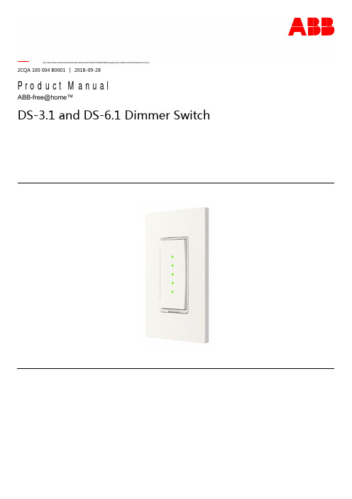
2CQA 100 004 B0001 │ 2018-09-28Product ManualABB-free@home™DS-3.1 and DS-6.1 Dimmer SwitchTable of Contents1The Device (3)1.1Basic Operation (3)2Adding the Dimmer Switch (4)3Configuring the Dimmer Switch (7)3.1Dimmer Switch Settings (7)3.2LED Settings (8)4Technical Data (10)4.1Technical Data: DS-3.1 and DS-6.1 (10)4.2Load Table DS-3.1 (10)4.3Load Table DS-6.1 (10)5Appendix (11)5.1Dimming LED’s (11)5.2Resetting the Device (11)The Device 1The DeviceThe Dimmer Switches are used to dim 120 V lighting devices continuously. They can beintegrated into the ABB-free@home™ Smart Home system allowing remote operation, i.e. bymobile devices (free@home System Access Point required).A binary input allows the connection of a mechanical switch to create a 3-way installation.DS-3.1 Dimmer Switch (2-wire)The DS-3.1 dims incandescent lamps up to 300 W or LED lamps up to 150 W.Note: No Neutral wire required.DS-6.1 Dimmer Switch (3-wire)The DS-6.1 dims incandescent lamps up to 600 W or LED lamps up to 150 W.Note: A neutral wire is required.1.1Basic OperationTo Turn ON: Short press at the top of the rocker switch.To Make Brighter: Long press at the top of the rocker switch.To Turn OFF: Short press at the bottom of the rocker switch.To Make Dimmer: Long press at the bottom of the rocker switch.*Safety-OFF Switch: This switch allows the user to turn OFF the power tosafely replace a lamp. However, the rocker may have been configured tooperate a lamp other than the one switched OFF by the Safety OFF. Beforereplacing a lamp, verify that the wires to the lamp do not have power. Turnthe lamp on, then operate the Safety OFF. If the lamp turns OFF when theSafety OFF is activated, it is safe to replace the lamp.LED Indicator: The 5 LED’s show the brightness level of the connected lighting.2Adding the Dimmer SwitchThis section describes how to add the Dimmer Switch to the system.STEP 1: Install the Dimmer SwitchInstall the device by following the Operating Instructions of DS-3.1 and DS-6.1 included in theoriginal packaging.Note: After installation, the Dimmer Switch will immediately allow the lamp to function. Tocontroltheswitchwirelessly,**************************************************** Switch has been assigned to a different SysAP, it will need to be reset. Please see here forinstructions.STEP 2: Open configuration and search for the Light SwitchEnsure that the SysAP is in Access Point mode by pressing the button on the SysAP. Theindicator light will turn solid blue. Connect to the SysAP by selecting it from the list in yourwireless network.Once connected, open a browser and enter 192.168.2.1 in the address line.If you have a tablet, use the free@home App.Note: It is not possible to set up the Dimmer Switch by using a smartphone.Log in as a user that has configuration rights.Start Go to Settings > free@home radio > Search for wireless devicesThe SysAP will now search for the Dimmer Switch.Note:The Dimmer Switch can only be found if the search starts within 30 minutes after the Dimmer Switch was connected to power. If 30 minutes has elapsed, the user must turn the power OFF and back ON again to restart the 30 minutes. You can do this by using the Safety-OFF Switch.The Dimmer Switch will be found automatically and will be inserted into the configuration software.Please wait until the Dimmer Switch configuration is read. This may take up to 10 minutes.STEP 3: Add the Dimmer to the floor planA. Go To “Devices”.B. Click on “Light”.C. Drag the light bulb symbol into the floor plan.D. Choose the device from the list.Note: The device can be identified by its serial number or 3-digit code.E. A new symbol will appear in the floor plan corresponding to the element that was placed into the floor plan.STEP 4: Add the Dimmer Switch to the floor planA. Click on “Sensors”.B. Drag the “Rocker” element into the floor plan. A new symbol will appear in the floor plan corresponding to the Rocker.STEP 5: Connect the Dimmer Switch to the LightA. Click on Rocker in the floor plan. Select “Rocker” from the drop-down menu that pops up.B. In the menu on the right-hand side of the screen, click on the button that says “Rocker”.C. Click on the Light in the floor plan. This creates a link between the two devices. (A linkbetween a Rocker and Light is shown below).3Configuring the Dimmer SwitchSTEP 1: Lamp SettingsClick on the lightbulb symbol to show the lamp settings.Define a name for this lamp.3.1Dimmer Switch SettingsSettingDescriptionOptionsImageType of LoadSets what type of bulb is connected to the controlDimmable LED/CFL Inductive Load Incandescent LampMinimumBrightness [%]Sets the minimum brightness the dimmer will dim to1 to 100 inincrements of 1Maximum switch-on brightness, day [%]Sets the maximum brightness the dimmer with start at when first turned on during the day1 to 100 inincrements of 1Maximum switch-on brightness,night [%]Sets the maximum brightness the dimmer with start at when first1 to 100 inincrements of 1turned on at night Autonomous switch off time duration [s]This setting is only used in combination with a motion detector.Dimmer Switch will automatically switch OFF after time has elapsed.30 to 1800 in increments of 10Switch-on modeDefines what happens with the rocker is switched ON.Last brightness Maximum BrightnessSTEP 2: Rocker SettingsAfter clicking on the rocker symbol, select “Rocker”.“Binary Input” is only used when the Binary Input is connected, (i.e. in a 3-way installation).3.2LED Settings SettingDescriptionOptionsImageLED switch-onbrightness night [%]User can adjust brightness of LED 0 to 100 in increments of1LED switch-on brightness day [%]User can adjust brightness of LED0 to 100 in increments of1LED modeLED lighting to help user navigate· “Orientation light”:LED is always ON to find Light Switch at night· “Status indication”:LED shows status of light, i.e. LED is ON when switch is ON,and OFF when switch is OFFTechnical Data 4 Technical Data4.1Technical Data: DS-3.1 and DS-6.1Description ValueOperating Voltage120 VAC, 60 HzOperating Voltage Range103 VAC to 121 VACConnection DS-3.1: No Neutral Wire RequiredDS-6.1: Neutral Wire RequiredBinary Input Voltage120 VAC NominalMaximum Power Consumption< 1 WStandby* Power Consumption< 300 mWTransmission Protocol free@home, 2.400 - 2.483 GHz, meshedTransmission Power< 15 dBmProtection Type IP 20Ambient Temperature Range23° F to 113° F (-5° C to 45° C)Storage Temperature Range-40° F to 140° F (-40° C to 60° C) *If output is off and no active wireless communication4.2Load Table DS-3.1Load Type ValueIncandescent or Halogen Lamps300 WMagnetic Low-Voltage Transformer (MLV)Not AllowedElectronic Low-Voltage Transformer (ELV)200 WCompact Fluorescent Lamps (CFL)150 WLED lamps, Maximum 20 Lamps Allowed150 WFan or Motors Not Allowed4.3Load Table DS-6.1Load Type ValueIncandescent or Halogen Lamps600 W*Magnetic Low-Voltage Transformer (MLV)600 W*Electronic Low-Voltage Transformer (ELV)600 WCompact Fluorescent Lamps (CFL)150 WLED Lamps, Maximum 20 Lamps Allowed150 WFan or Motors Not Allowed*If 3 Dimmer Switches are mounted next to each other in a 3-gang installation, the maximum output powerper device will be reduced to 550 W.5Appendix5.1Dimming LED’sSome LED’s are not easy to dim. If you have issues, please follow this guide first:STEP 1: Right settingIn the DEVICES view click on the lamp and have a lock on the right at the LIST VIEW.Put “Type of load’” to “Dimmable LED/CFL”.STEP 2: Are the LED’s flickering?Some LED’s tend to flicker close to 100%. Reduce the “Maximum brightness” setting (day andnight) to a lower value, e.g. 90%.Some LED’s flicker when dimming down. In this case increase the “Minimum brightness”:STEP 3: LED remains ONSome LED’s still produce some light even after the Dimmer Switch switches them off. Werecommend to replace the LED in this case.Note: Please send us a short note with the manufacturer and type of the lamp together withdate and seller where you purchased the lamp. ABB will provide a list of incompatible lamps.Furthermore it helps us in continuously improving the Dimmer Switches.5.2Resetting the DeviceReset the Light Switch if it was previously assigned to a different System Access Point (SysAP).The reset will remove any previous connection and enable the device to connect to a newSysAP.Reset procedure:A) Press and hold the bottom of the rocker for at least 20 seconds.B) The bottom LED light will start flashing after 10 seconds.C) After another 5 seconds, the LED will start flashing rapidly. After another 5 seconds, the LEDlight will turn off.D) Release the bottom of the rocker within the next 10 seconds.E) Then press the bottom of the rocker. The lower LED light will stay on. Press the bottom of the rocker again. The previous actions must be completed within 5 seconds.F) The device will now return to factory settings and restart.ABBElectrification Products860 Ridge Lake Boulevard Memphis, TN 38120/freeathomeCustomer Service:800-816-78097:00 am – 5:30 pm, CST, Mon-Fri*********************Technical Support:888-385-1221, Option 17:00 am – 5:00 pm, CST, Mon-Fri*****************************.com For information about the many functions of this device, see the system manual at/us/freeathomeNoticeWe reserve the right at all times tomake technical changes as well aschanges to the contents of thisdocument without prior notice.The detailed specifications agreedupon apply for orders. ABB acceptsno responsibility for possible errorsor incompleteness in thisdocument.We reserve all rights to thisdocument and the topics andillustrations contained therein. Thedocument and its contents, orextracts thereof, must not bereproduced, transmitted or reusedby third parties without prior writtenconsent by ABB ProductManual2CQA14B1│218-9-28© 2018 ABB Inc.All rights reserved。
ABB C56x 电子定时器说明书

DescriptionC56x timing relays are snapped directly onto a 35mm DIN rail safely and easily in accordance with DIN VDE 50 022. Assembly and disas-sembly can be performed without complica-tions or tools. Screw fastening accessories are available. The connection terminals and maximum permissible connection crosssections are optimally tailored to each other to allow trouble-free connection of the timing relay to the control lines and automation compo-nents.C56x timing relays have a high 230 VAC/VDC switching capacity within the permissible operating range of -25°C to +60°C (-13°F to +140°F). Even when switching contactors,relays from ABB distinguish themselves by their long electrical service life.The precise running time setting is made on the ergonomically designed front control and display element of the C56x timing relay.Fifteen switchable time ranges can each be set in seconds, minutes or hours with the end values 1, 3, 10, 30 and 100.“Continuous switching” with defined ON/OFF switching is also possible for test purposes.Two LEDs indicate the supply voltage and relay connections. All functions are clearly and unmistakably identified in English on the circuit diagram and corresponding labeling, so that it is extremely difficult to accidently adjust the timing relay. The electronics, which are safe in every respect, cannot be influenced byinterference and ensure reliable operation of the C56x timing relay – even on coils without surge suppression.Selection guideC561.10C561.01C561.02C561.13 footnotes?Selection guideC562.10C562.20C563C564C565IP 201 x (0.5 – 4)2 x (0.5 – 2.5)1 x (0.5 – 2.5)2 x (0.5 – 1.5)C561.10DescriptionAfter energizing Ax/A2, the time delay starts. The first LED illuminates as long as the terminals Ax/A2 are energized. Afterthis delay time the relay changes state and remains in this position till the relay is de-energized. The second LED alwaysindicates the states of the contacts.C561.1015/1815/16A1/A2Function diagram Wiring diagram Terminal connectionC561.01DescriptionAfter energizing Ax/A2, the first LED illuminates as long as the terminals are energized. After the delay time the twocontacts change state and remain in their position until the relay is de-energized. The second LED always indicates thestate of the contacts.C561.0115/18Function diagram Wiring diagram Terminal connectionC561.13After energizing Az/A2, the Y-contact (17/18) will close and remain in this position as long as the chosen Y-time. Then the contact opens again.After 50ms of safety time delay, the d-contact (17/28) will close.C561.13Wrong artNeed SST 7956NOT AVAILABLEFunction diagram Wiring diagram Terminal connectionC562.10DescriptionAfter the control switch “S” closes for at least 35ms, the output relay is energized. The first LED indicates the energizing of terminals Ax/A2. If the control switch opens, the timing period begins. If the control switch closes before the timing period elapses, the output relay remains energized and the timing period is reset. When the timing period elapses, the output relay de-energizes. The second LED always indicates the state of the contacts.C562.10Function diagram Wiring diagram Terminal connectionC562.20DescriptionThis off delay works without auxiliary voltage.After energizing Ax/A2 (for at least 200ms) the first LED illuminates as long as the terminals are energized.The contact changes state when supply voltage is applied.C562.20AC100/127VFunction diagram Wiring diagram Terminal connectionC563DescriptionAfter energizing terminals Ax/A2 the LED illuminates and the interval time starts. After the interval time, the contact change state, the second LED illuminates, and the pulse time starts.Both the interval and the pulse time range can be separately adjusted from 1 second – 100 hours.AC100/127VC563Function diagram Wiring diagram Terminal connectionC565Functions A – G are the same as relay C564.The two contacts with these functions arealways in the same state. Additional functionsA – YD follow:A On delay and instantaneous contact —when Ax/A2 terminals are energized, onecontact switch changes stateinstantaneously, and the other outputcontact changes state after time delay t.The second LED illuminates with thecontact 15/18.Function diagramsOn-delayInstantaneous contactWiring diagramB Off delay with auxiliary voltage andinstantaneous contact — When controlcontact closes (Bx/A2), both outputcontacts (15/18), (21/24) changes stateimmediately. When control contact opens,output contact (21/24) changes state aftertime delay t. The second LED shows thestate of the contact (21/24). Constantsupply voltage required on terminals Ax/A2.Function diagramsOn-delayInstantaneous contactWiring diagramDescriptionC565C On – and off – delay with auxiliaryvoltage (t = t on = t off) andinstantaneous contact — When controlcontact S closes (Bx/A2), one contact (21/24) changes state instantaneously, theother output contact (15/18) changesstate after time delay t. When controlcontact S opens, output contact (15/18)changes state again after time delay t.Constant supply voltage is required onterminals Ax/A2.Function diagramsOn-delayInstantaneous contactWiring diagram1 When DC voltage is applied, operating range is (0.85 - 1.10) x UsDFlashing, starting with interval (pulse/interval 1:1) and instantaneous contact — When the terminals Ax/A2 areenergized, one output contact (21/24)changes state instantaneously, the other output contact (15/18) changes state after time period t,and then repeatedly changes again after every period t, continuing until supply voltage is removed. The second LED illuminates with the states of (15/18).Function diagramsOn-delayInstantaneous contactWiring diagramERising edge pulse and instantaneous contact — When terminals Ax/A2 are energized, both outputs changes state instantaneously. The output (15/18)changes state with the rising edge, and generates an impulse of the length t. The other output (21/24) changes state with the supply voltage. The second LED illuminates with the states of (15/18).Function diagramsOn-delayInstantaneous contactWiring diagramFFalling edge pulse with auxiliaryvoltage and instantaneous contact —When terminals Ax/A2 are energized, one contact (21/24) changes stateinstantaneously. With the falling edge of the control contact “S,” the other output (15/18) changes state and generates an impulse of the length t. The second LED illuminates with the states of (15/18).Function diagramsOn-delayInstantaneous contact25/26A1/A2B1/A2Wiring diagramG Pulse forming with auxiliary voltageand instantaneous contact — When terminals Ax/A2 are energized, bothoutputs change state instantaneously. The output contact (15/18) generates animpulse which length is not dependent on duration of energizing B1/A2. The output contact (21/24) changes state when the control contact S closes. The second LED illuminates with the states of (15/18).Function diagramsOn-delayInstantaneous contactA1/A2Wiring diagramC565HCumulative on-delay with auxiliary voltage – xxxxxxxxx xxxxx x x xxxxx xxxx x x x xxxxx x x xx xxxx x x x x xxx xxxx x x x xxxxx x x xx xxxx x x x x xxx xxxx x x x xxxxx x x xx xxxx x x x x xxxFunction diagramsOn-delayWiring diagramWye-delta function — After energizing Ax/A2, the y-contact 17/18 will close and remain in this position as long as the chosen y-time. Then the contact opens again. After 50ms of safety time delay, the d-contact 17/28 will close. The second LED will indicate the changing contact.Function diagramsOn-delayWiring diagramNeed textAccessoriesAccessories7215341SAR390000R10001SAR390000R3000 (C564)1SAR390000R4000 (C565)1SAR390000R20006Installation of label plates Installation of sealable cover Installation of fastening adapter2123A1.5 min5s1234Adjusting the timing settingsInstallationAccessoriesChanges to time range and functions1A1/AE power2 B1/B3 power1215/17C21/25/27C22/26 NC24/28 NO18 NOU s = AC/DC 24VL1U s = AC/DC 60VU s = AC100 - 127VU s = AC200 - 240VL1Changes to the time range and functions take effect only when de-energized.Same potential applied to A1 and B1 on A3 and B3. In case of dual-voltageversions, connect only on voltage range in each case.In case of AC, loads in parallel with the start input are not permitted.Technical data to IEC 1812-1/DIN VDE 0435, Part 20021Time relayC 562.10C 561.10 C 562.20C 561.13C 561.02C 564 C 561.01C 565 C 563Mechanical service life operations30 · 106100 · 106Rated insulated voltageAC V 250Permissible ambient temperature °C – 25 to + 60 (during operation)°C– 40 to + 80 (storage)Operating range of excitation 10.85 to 1.1 x U s with AC; 0.8 to 1.25 x U s with DC 0.95- to 1.05times rated frequency Rated powerW 22222at AC 230 V, 50 HzVA 662 2)60.5Rated operating currents I eAC-15 at AC 230 V, 50 Hz A 30.01 to 0.5DC-13 at DC 24 V A 1DC-13 at DC 230 VA 0.1Fusing DIAZED 3A4Utilisation category gL/gG,Switching frequencywhen loaded with I e , AC 230 V1/h 25005000when loaded with contactors B6, B7, AC 230 V 1/h 50005000Recovery time ms 15050Minimum ON period ms 35–200 4)––Residual currentmA m 5Voltage drop in conductive state V m 3.5Short-time withstand capability A10(up to 10 ms)Setting tolerancetypically w 5%referred to full scale value Repeat accuracy m w 1% over the entire time range EnclosureIP 20to DIN EN 60 529Conductor connectorsingle-coremm 1 x (0.5 – 4)2 x (0.5 – 2.5)flexible with wire end ferrule mm 1 x (0.5 – 2.5)2 x (0.5 – 1.5)single-core or strandedAWG2 x (20 – 14)Terminal screwsM 3.5Permissible normal position anyResistance to shock g /ms15/11semi-sinusoidal to IEC 68Technical data1 Unless otherwise specified2 Maximum peak inrush current 1 A/100 ms3 With no contact welding whatsoever in accordance with DIN VDE 0660, Part 2000.4 Comply with minimum excitation time for proper operation.Where are footnotes 2 and 4, above?Approximate dimensions1) Plug-in tab for screw mounting 2) Sealable cover plate3) Identification label (for C564 and C565)C561.10, C561.02, C561.13C562.20, C5631 changeover contact without auxiliary voltage,two-wire version, clock generatorC561.01, C562.10C564, C5651 changeover contact with auxiliary voltage,2 changeover contacts。
ABB CT-AHE电子计时器数据表说明书
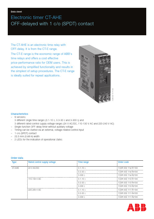
1S V R 550 111 F 1100Electronic timer CT-AHEOFF-delayed with 1 c/o (SPDT) contactThe CT-AHE is an electronic time relay with OFF-delay. It is from the CT-E range.The CT-E range is the economic range of ABB‘s time relays and offers a cost effectiveprice-performance ratio for OEM users. This is achieved by simplified functionality and results in the simplest of setup procedures. The CT-E range is ideally suited for repeat applications.Characteristics –9 versions:3 different single time ranges (0.1-10 s, 0.3-30 s and 3-300 s) and3 different rated control supply voltage ranges (24 V AC/DC, 110-130 V AC and 220-240 V AC) –Single-function OFF-delay timer without auxiliary voltage–Timing can be started via an external, voltage-related control input – 1 c/o (SPDT) contact –22.5 mm (0.89 in) width– 2 LEDs for the indication of operational statesOrder dataType Rated control supply voltage Time range Order codeCT-AHE24 V AC/DC0.1-10 s 1SVR 550 118 R11000.3-30 s 1SVR 550 118 R41003-300 s1SVR 550 118 R2100110-130 V AC0.1-10 s 1SVR 550 110 R11000.3-30 s 1SVR 550 110 R41003-300 s1SVR 550 110 R2100220-240 V AC0.1-10 s 1SVR 550 111 R11000.3-30 s 1SVR 550 111 R41003-300 s1SVR 550 111 R21002 - Electronic timer CT-AHE | Data sheetFunctions Operating controls1S V R 550 111 F 1101 Indication of operational statesU: green LED – Control supply voltage applied R: red LED – Output relay energized2 Thumbwheel for the fine adjustment of the time delayApplicationTheir conception makes the CT-E range timers ideal for repeat applications.Operating modeThe fine adjustment of the time delay is made via the front-face thumbwheel.Function diagramB OFF-delay with auxiliary voltage (Delay on break)This function requires continuous control supply voltage for timing. Timing is controlled by control input A1-Y1. If the control input is closed, the output relay energizes. If control input A1-Y1 is opened, the selected time delay starts. When the time delay is complete, the output relay de-energizes. If control input A1-Y1 is closed before the time delay is complete, the time delay is reset. Timing starts again when the control input re-opens.Electrical connectionWiring notesData sheet| Electronic timer CT-AHE - 3Data at T a = 25 °C and rated values, unless otherwise indicatedInput circuitsSupply circuitRated control supply voltage U s A1-A2depending on device: 24 V AC/DC, 110-130 V AC, 220-240 V AC Rated control supply voltage U s tolerance-15...+10 %Rated frequency AC/DC version DC or 50/60 HzAC version50/60 HzTypical current / power consumption24 V AC/DC approx. 1.0 VA/W110-130 V AC approx. 2.0 VA220-240 V AC approx. 2.0 VARelease voltage> 10 % of the minimum control supply voltageControl circuitControl input, control function A1-Y1start timing externalKind of triggering voltage-relatedParallel load noPolarized yesControl voltage potential rated control supply voltageMinimum control pulse length20 msTiming circuitTime range depending on device: 0.1-10 s, 0.3-30 s or 3-300 sRecovery time< 50 msRepeat accuracy (constant parameters)D t < 1 %Accuracy within the rated control supply voltage tolerance D t < 0.5 % / VAccuracy within the temperature range D t < 0.1 % / °CSetting accuracy of time delay± 10 % of full-scale valueUser interfaceIndication of operational statesControl supply voltage U: green LED V: control supply voltage appliedRelay status R: red LED V: output relay energizedOutput circuitKind of output15-16/18relay, 1 c/o (SPDT) contactContact material silver alloyRated operational voltage U e250 VMinimum switching voltage / current12 V / 100 mAMaximum switching voltage / current see ‚Load limit curves‘Rated operational current I e AC-12 (resistive) at 230 V 4 AAC-15 (inductive) at 230 V 3 ADC-12 (resistive) at 24 V 4 ADC-13 (inductive) at 24 V 2 AAC rating (UL 508)Utilization category(Control Circuit Rating Code)B 300max. rated operational voltage300 V ACMaximum continuous thermal current at B300 5 Amax. making/breaking apparent power at B3003600 VA / 360 VAMechanical lifetime10 x 106 switching cyclesElectrical lifetime AC-12, 230 V, 4 A0.1 x 106 switching cyclesFrequency of operation with/without load360/72000-1Maximum fuse rating to achieve short-circuit protection n/c contact10 A fast n/o contact10 A fast4 - Electronic timer CT-AHE | Data sheetMTBF on requestDuty time100 %Dimensions see ‘Dimensional drawings’Weight net weight1SVR550118R11000.064 kg (0.141 lb)1SVR550118R41000.070 kg (0.154 lb)1SVR550118R21000.064 kg (0.141 lb)1SVR550110R11000.067 kg (0.148 lb)1SVR550110R41000.068 kg (1.450 lb)1SVR550110R21000.067 kg (0.148 lb)1SVR550111R11000.067 kg (0.148 lb)1SVR550111R41000.067 kg (0.148 lb)1SVR550111R21000.068 kg (1.450 lb)gross weight1SVR550118R11000.077 kg (0.170 lb)1SVR550118R41000.081 kg (0.179 lb)1SVR550118R21000.077 kg (0.170 lb)1SVR550110R11000.080 kg (0.176 lb)1SVR550110R41000.081 kg (0.179 lb)1SVR550110R21000.080 kg (0.176 lb)1SVR550111R11000.080 kg (0.176 lb)1SVR550111R41000.080 kg (0.176 lb)1SVR550111R21000.081 kg (0.179 lb)Mounting DIN rail (IEC/EN 60715), snap-on mounting without any toolMounting position anyMinimum distance to other units not necessaryMaterial of housing lower section UL 94 V-0upper section UL 94 V-2Degree of protection housing IP50terminals IP20Electrical connectionConnecting capacity fine-strand with wire end ferrule 2 x 0.75-1.5 mm2 (2 x 18-16 AWG)fine-strand without wire end ferrule 2 x 1-1.5 mm2 (2 x 18-16 AWG)rigid 2 x 0.75-1.5 mm2 (2 x 18-16 AWG)Stripping length10 mm (0.39 in)Tightening torque0.6-0.8 Nm (5.31-7.08 lb.in)Environmental dataAmbient temperature ranges operation -20...+60 °Cstorage-40...+85 °CRelative humidity range 4 x 24 h cycle, 40 °C, 93 % RHVibration, sinusoidal IEC/EN 60068-2-620 m/s², 10-58/60-150 HzShock, half-sine IEC/EN 60068-2-27150 m/s², 11 ms, 3 shocks/directionIsolation dataRated insulation voltage U i between all isolated circuits Control supply voltage up to 240 V: 300 VControl supply voltage up to 440 V: 500 VRated impulse withstand voltage U imp between all isolated circuits 4 kV / 1.2-50 μsbetween all isolated circuits 2.5 kV, 50 Hz, 1 min.Power frequency withstand voltage(test voltage)Basic insulation (IEC/EN 61140)input/output300 VProtective separation (IEC/EN 61140, EN 50178)input/output-Pollution degree3Overvoltage category IIIData sheet| Electronic timer CT-AHE - 56 - Electronic timer CT-AHE | Data sheetStandards / DirectivesStandardsIEC/EN 61812-1Low Voltage Directive 2014/35/EU EMC Directive 2014/30/EU RoHS Directive2011/65/EUElectromagnetic compatibilityInterference immunity toIEC/EN 61000-6-2electrostatic discharge IEC/EN 61000-4-2Level 3 (6 kV / 8 kV)radiated, radio-frequency, electromagnetic fieldIEC/EN 61000-4-310 V/m (1 GHz), 3 V/m (2 GHz), 1 V/m (2.7 GHz)electrical fast transient / burst IEC/EN 61000-4-4Level 3 (2 kV / 5 kHz)surgeIEC/EN 61000-4-5Level 4 (2 kV L-L)conducted disturbances, induced by radio-frequency fields IEC/EN 61000-4-6Level 3 (10 V)Interference emissionIEC/EN 61000-6-3high-frequency radiated IEC/CISPR 22, EN 55022Class B high-frequency conductedIEC/CISPR 22, EN 55022Class BTechnical diagrams Load limit curvesAC load (resistive)DC load (resistive)Derating factor F for inductive AC loadContact lifetime /switching cycles N 220 V AC 50 Hz AC1, 360 cycles/hDimensionsin mm andinchesFurther documentationDocument title Document type Document numberElectronic relays and controls Catalog2CDC 110 004 C02xxYou can find the documentation on the internet at /lowvoltage-> Automation, control and protection -> Electronic relays and controls -> Time relays.CAD system filesYou can find the CAD files for CAD systems at -> Low Voltage Products & Systems -> Control Products -> Electronic Relays and Controls.Data sheet| Electronic timer CT-AHE - 7ABB STOTZ-KONTAKT GmbHP. O. Box 10 16 8069006 Heidelberg, Germany Phone: +49 (0) 6221 7 01-0Fax: +49 (0) 6221 7 01-13 25E-mail:*****************.comYou can find the address of your local sales organisation on theABB home page/contacts-> Low Voltage Products and Systems Contact usNote:We reserve the right to make technical changes or modify the contents of this document without prior notice. With regard to purchase orders, the agreed particulars shall prevail. ABB AG does not accept any responsibility whatsoever for potential errors or possible lack of information in this document.We reserve all rights in this document and in the subject matter and illustrations contained therein. Any reproduction, disclosure to third parties or utilization of its contents – in wholeor in parts – is forbidden without prior written consent of ABB AG.Copyright© 2017 ABBAll rights reserved D o c u m e n t n u m b e r 2 C D C 1 1 1 1 3 6 D 0 2 0 1 ( 0 3 . 2 0 1 7 )。
abb eki pconnect 智能型断路器操作手册说明书

—E A S E OF I NTER AC TI O NEkip ConnectAccess the full potential of your ABB circuit breakercommissioning software to unlockthe full potential of circuit breakers,and improve the efficiency of theplant.day-by-day process.For this reason, it is vital that the installation anduse of the circuit breaker are made as error-free andsimple as possible.From commissioning to implementation, throughmonitoring, testing and analysis, Ekip Connect isthe perfect tool to drive the user in the managementof ABB circuit breakers throughout the wholeproduct life cycle.Ekip Connect is the ABB commissioning andprogramming software allowing full exploitation ofEkip trip unit’s potential. Using Ekip Connect, theuser can manage power, acquire and analyzeelectrical values and test protection, maintenanceand diagnostic functions.If the Ekip architecture takes the circuit breakers tothe next level, Ekip Connect software becomes theuser’s key to access that level and exploit the newunique features developed by ABB.Ease of useImagine you are a panel builder. You have to commission a circuit breaker and you need to save time.Using Ekip Connect – instead of managing it manually – you can cut commissioning time up to 50%.Providing a stress-free relationship with the device complexity, Ekip Connect is an easy-to-use software that has all the answers you need.Ekip Connect simple and intuitive interface guarantees, from the very start, easy navigation throughout the tool and quick access to every circuit breaker operation.At a glance, the user can see all the information he needs, thus being able to quickly and effectively assess any situation.Full exploitationImagine you are a facility manager. You need to perform fast and precise diagnosis to have everything under control and avoid failures.Using Ekip Connect you can exploit the full capabilities of your device and, thanks to the customizable dashboard, you can organize your windows to manage any function of the device just the way you want it.It is possible to manage all the circuit breaker settings and specifications directly with Ekip Connect, the perfect instrument for exploring and using the breaker.Diagnostics are easy too: it is possible to consult and download event log, alarms and trips, thereby facilitating identification and understanding of any anomalies.One single software to manage all ABB low-voltage circuit breakers equipped with an electronic trip unit, granting full integration between air and molded case circuit breakers. Product enhancementImagine you are a consultant or a system integrator and you want to implement advanced features while avoiding any risk of mistakes.Using Ekip Connect you can implement complex logics with just a few clicks.To add, set and manage advanced functions has never been so easy. Cloud platform, automatic transfer switch logic, load shedding, advanced protection and demand management can be managed and easily set through the Ekip Connect software. Expand your software features by purchasing and downloading software packages for advanced functions directly using Ekip Connect.Panel builder- 50% commissioning timeFacility manager+100% full exploitation of your device Consultant/System integratorComplex logics at your fingertipAccessing the full potential of ABB low-voltage circuit breakers at your fingertips.Thanks to Ekip Connect software, you can achieve the full exploitation with few clicks of your mouse.ConfigurationProduct implementation Monitoring & analysis Testing & reporting• Set protections• Configure system andcommunication parameters • Circuit breaker start-up• Set advanced protections • Logics activation• Enable advanced functions• View circuit breaker status and measures • Read event list• Circuit breaker diagnostics• Check correct functionality • Test performance • Report exportEkip Connect is available for free download at /abblibrary/DownloadCenter/1S D C 210102D 0201 - 2018.03/lowvoltage—ABB SACEA divison of ABB S.p.A.L.V. Breakers Via Pescaria, 524123 Bergamo - Italy Phone: +39 035 395.111Fax: +39 035 395.306-433—We reserve the right to make technical changes or modify the contents of this document without prior notice. With re-gard to purchase orders, the agreed par-ticulars shall prevail. ABB does not accept any responsibility whatsoever for potential errors or possible lack of information in this document.We reserve all rights in this document and in the subject matter and illustrations con-tained therein. Any reproduction, disclo-sure to third parties or utilization of its contents – in whole or in parts – is forbidden without prior written consent of ABB. Copyright© 2017 ABB All rights reserved。
- 1、下载文档前请自行甄别文档内容的完整性,平台不提供额外的编辑、内容补充、找答案等附加服务。
- 2、"仅部分预览"的文档,不可在线预览部分如存在完整性等问题,可反馈申请退款(可完整预览的文档不适用该条件!)。
- 3、如文档侵犯您的权益,请联系客服反馈,我们会尽快为您处理(人工客服工作时间:9:00-18:30)。
SW/S4.5定时器操作手册一、初始设定初始操作:确保锂电池已插入。
按功能选择键(椭圆带箭头符号对应的按键)移动光标(三角形光标),选择不同的功能菜单每按一下选择键,光标将移动一位。
结束编程:按选择键将光标移至 “Auto”下面。
移动光标可选择的符号的功能如下:Auto: 自动定时控制状态。
时钟符号:设置/改变日期及时间。
?:查询,更改,删除,完全删除。
Prog: 定时编程脉冲符号:日,周脉冲编程。
P:节假日编程。
太阳/雪花符号:夏时制/冬令时编程。
1.输入调整SW/S4.5具有提示功能,根据正在闪动的符号,便可指导当前所处的编程位置。
输入调整:当输入了一个错误的值怎么办?取消编程步骤:-按CL键=退回上一步-重复按CL键=重复退回上一步当错误值闪动时:-用0…9按键输入正确值在通道编程或周-日定时编程时出错:-再按一次同样的按键注意:只有最后一次的输入被取消。
2.日期及时间设定按一下RES键复位,进行初始化。
举例:日期设定为:19.05.2000,时间为:9.25-按RES键复位。
-按1键及9键输入日-按0键及5键输入月-按0键及0键输入年-按0键及9键输入小时-按2键及5键输入分钟-按enter键保存注意:初始化操作后,自动夏时制/冬令时转换时间已自动编制好并供选择。
-默认设定为欧洲夏时制/冬令时:dat 1。
-如果需要其他夏时制/冬令时或不需要夏时制/冬令时切换,也可随时修改。
夏时制/冬令时选择表:dat 0: 无夏时制/冬令时dat 1: 欧洲dat 2: 英国dat 3: 北美dat 4: 可采用软件自行编制3.选择夏时制/冬令时:默认设置:SW/S4.5: dat 1选择新的切换时间:例如:将 dat 1改为dat 0即无夏时制/冬令时切换。
-按6次选择键,将光标移至太阳/雪花符号下面。
-按Dat.键。
-按0键。
-按enter键保存。
-按选择键,将光标移至Auto符号下面。
4.修改日期:按一下选择键将光标移至时钟符号的下面,然后便可对闪动的数据进行修改,按0…9键可输入实际的时间及日期。
例如:修改日期将19.5.2000改为20.5.2000,将时间 9.25改为 9.27。
-按一下选择键将光标移至时钟符号的下面-按Dat键,日期闪动-按2键及0键,输入日-按enter键,保存月份-按enter键,保存年,时间闪动-按0键及9键,输入小时-按2键及7键,输入分钟-按enter键保存-重复按选择键将光标移至Auto下面结束二、定时编程1.永久开/关每个通道均可手动将其改为永久开的状态。
永久开具有最高权限,此通道将保持开的状态直至手动将其取消。
例如:通道1永久开-光标在Auto下面-按1键选择通道1-按P键-按1键,永久开例如:通道1永久关-光标在Auto下面-按1键选择通道1-按P键-按0键,永久关每个通道均可手动将其改为永久关的状态。
永久关具有最高权限,此通道将保持关的状态直至手动将其取消。
永久开/关取消后,自动定时功能将恢复。
2.手动开/关(插入开关)每个通道均可在自动状态下手动将其改为开的状态,同时显示屏上将显示H=手动。
下一次开关命令将取消此手动开, H显示消失。
选择通道:例如按键1=通道1(C1),按键2=通道2(C2)等。
选择状态:按键1=开,按键0=关举例:手动开通道4,在Auto状态下,按一下按键4,再按一下按键1,通道4手动开,显示屏上C4左边的半圆中有一横线出现,表示开,另有一个H字母出现在显示屏上,表示手动。
每个通道均可在自动状态下手动将其改为关的状态,同时显示屏上将显示H=手动。
下一次开关命令将取消此手动关, H显示消失。
选择通道:例如按键1=通道1(C1),按键2=通道2(C2)等。
选择状态:按键1=开,按键0=关举例:手动关通道4,在Auto状态下,按一下按键4,再按一下按键CL,通道4手动关,显示屏上C4左边的半圆中的一横线消失,表示关,另有一个H字母出现在显示屏上,表示手动。
3.定时编程周程序,设置定时开时间:周程序,设置定时开时间举例:通道C1及C3从星期一至星期五每天6:30开,按周循环。
-选择编程模式,按3次选择键,将光标移至Prog下面-选择通道,按1按键及3按键,选择通道C1及C3-按enter键确认所选的通道-按1按键,表示“开”,显示屏上C1及C3左边的半圆中有一横线出现,表示开-输入“日”,按1按键,2按键,3按键,4按键,5按键,分别选中星期一至星期五-按enter键,确认所选的“日”-输入时间,按0键及6键,输入小时即6点钟,再按3键及0键,输入分钟即30分-按enter键,保存编程-结束编程:重复按选择键,将光标移至Auto下面,结束编程。
周程序,设置定时关时间:周程序,设置定时关时间举例:通道C1及C3从星期一至星期五每天18:30关,按周循环。
-选择编程模式,按3次选择键,将光标移至Prog下面-选择通道,按1按键及3按键,选择通道C1及C3-按enter键确认所选的通道-按0按键,表示“关”-输入“日”,按1按键,2按键,3按键,4按键,5按键,分别选中星期一至星期五-按enter键,确认所选的“日”-输入时间,按1键及8键,输入小时即18点钟,再按3键及0键,输入分钟即30分-按enter键,保存编程-结束编程:重复按选择键,将光标移至Auto下面,结束编程。
日期程序:举例:通道C1每年5月1日7:30开-选择编程模式,按3次选择键,将光标移至Prog下面-选择通道,按1按键,选择通道C1-按enter键确认所选的通道-按1按键,表示“开”-按Dat.按键-输入“日”,按0按键及1按键,输入“日”-输入“月”,按0按键及5按键,输入“月”-输入“小时”,按0按键及7按键,输入“小时”-输入“分钟”,按3按键及0按键,输入“分钟”-按enter键,保存编程-结束编程:重复按选择键,将光标移至Auto下面,结束编程。
4.一次性开关定时编程:举例:通道C2,5月10日,8点30分,一次性开。
注意:一旦定时时间到并发出定时开关命令后,此一次性定时将在午夜后自动取消。
-选择编程模式,按3次选择键,将光标移至Prog下面-选择通道,按2按键,选择通道C2-按enter键确认所选的通道-按1按键,表示“开”,显示屏上C2左边的半圆中有一横线出现,表示开-按Dat.按键-输入“日”,按1按键及0按键,输入“日”-输入“月”,按0按键及5按键,输入“月”-输入“小时”,按0按键及8按键,输入“小时”-输入“分钟”,按3按键及0按键,输入“分钟”-按1按键,表示一次性开-按enter键,保存编程-结束编程:重复按选择键,将光标移至Auto下面,结束编程。
5.脉冲式开关定时编程:举例:通道C1及C2脉冲式开关,时长:5秒钟,7:15开始,从星期一至星期五,按周循环。
-选择编程模式,按4次选择键,将光标移至脉冲符号下面-选择通道,按1按键及2按键,选择通道C1及C2-按enter键确认所选的通道-按1按键,表示“开”,显示屏上C1及C2左边的半圆中有一横线出现,表示开-选择周“日”,按1按键,2按键,3按键,4按键,5按键,表示选中星期一至星期五-按enter键确认-输入“小时”,按0按键及7按键,输入“小时”-输入“分钟”,按1按键及5按键,输入“分钟”-输入脉冲时长,按0按键及5按键,表示开5秒钟-按enter键,保存编程-结束编程:重复按选择键,将光标移至Auto下面,结束编程三、优先定时编程:1.优先程序:除了正常的周程序外,SW/S4.5还可编制9种不同的具有优先权的周程序。
周程序P1…P9可用于任何一个固定的时间段内。
这种程序包括:-周程序编程-设定开始及结束日期如果在时间段内,周程序相互交叉,高序号的程序将优先于低序号的程序,如周程序P9将优先于周程序P3。
开关时间按如下顺序执行:-永久开关程序-一次性开关程序-有时间限制的永久开关程序-日期程序-具有优先权的周程序。
-周程序2.具有优先权的周程序编程:举例:通道C1及C2,每天8:15定时开。
周程序优先级别P1。
-选择编程模式,按3次选择键,将光标移至Prog下面-选择通道,按1按键及2按键,选择通道C1及C2-按enter键确认所选的通道-按1按键,表示“开”,显示屏上C1及C2左边的半圆中有一横线出现,表示开-按0按键,表示选中星期一至星期日-按enter键确认-输入“小时”,按0按键及8按键,输入“小时”-输入“分钟”,按1按键及5按键,输入“分钟”-按1按键,表示此周定时程序优先级别为P1-按enter键,保存编程-结束编程:重复按选择键,将光标移至Auto下面,结束编程3.具有优先权的周程序P1…P9时间段设定:周程序P1…P9起始/结束日期的时间段可自行输入,此周程序于起始日的0:00开始,于结束日的24:00中止。
举例:在正常的周程序的基础上,通道C1从4月8日至5月27日,优先周程序P1将起作用,在此时间段内,正常的周程序(不具有优先权的周程序)将不起作用,并被优先程序替代。
-选择优先周程序编程模式,按5次选择键,将光标移至P下面-选择通道,按1按键,选择通道C1-按enter键确认所选的通道-输入起始日期,按0按键,8按键,0按键,4按键,输入日期-按enter键确认所输入的日期-输入结束日期,按2按键,7按键,0按键,5按键,输入日期-按1按键,表示优先级为1-按enter键,保存编程-结束编程:重复按选择键,将光标移至Auto下面,结束编程4.特定一年中的周程序举例:2000年4月8日至5月27日,采用周程序P2。
-选择优先周程序编程模式,按5次选择键,将光标移至P下面-选择通道,按2按键,选择通道C2-按enter键确认所选的通道-输入起始日期,按0按键,8按键,0按键,4按键,0按键,0按键,输入日月年-输入结束日期,按2按键,7按键,0按键,5按键,输入日月-按2按键,表示优先级为2-按enter键,保存编程-结束编程:重复按选择键,将光标移至Auto下面,结束编程5.限定时间段内的永久开/关举例:所有设备在圣诞节12月23日至1月7日期间关闭。
-选择优先周程序编程模式,按5次选择键,将光标移至P下面-选择通道,按1按键,2按键,3按键,4按键,选择通道C1,C2,C3,C4-按enter键确认所选的通道-输入起始日期,按2按键,3按键,1按键,2按键,输入日期-输入年,按9键,9键,表示1999年-输入结束日期,按0按键,按7键,按0键,按1键,输入日期-按P按键,表示永久开/关,显示屏C1,C2,C3,C4左边显示P字母-按0按键,表示关-按enter键,保存编程-结束编程:重复按选择键,将光标移至Auto下面,结束编程四、编程内容查询1.查询所有编程内容:按2次选择键(椭圆带箭头符号对应的按键),将光标移至“?”下面,表示进入查询功能。