GIS开发技术文档
GIS原型系统开发报告

GIS原型系统开发报告学院:信息工程学院班级:114131团队:Big big six组长:蒋文佳组员:张金生、张志鹏、赵泽军、罗文森、熊慧敏目录1 引言 (4)项目背景 (4)系统需求分析 (4)可行性分析 (4)项目组成员简介 (5)项目管理 (5)评分标准 (5)2 软件安装与卸载 (5)GIS原型软件的安装与卸载 (5)三级标题 (5)三级标题 (5)三级标题 (5)SQL Server数据库的安装与卸载 (5)三级标题 (5)三级标题 (5)三级标题 (5)3 软件功能与特点 (6)软件特色 (6)软件界面介绍 (6)要素的存储与查询 (6)点要素 (6)线要素 (6)区要素 (6)要素的可视化 (6)点要素 (6)线要素 (7)区要素 (7)要素的编辑 (7)点要素 (7)线要素 (7)区要素 (7)4 软件扩展模块 (7)测距 (7)三级标题 (7)三级标题 (7)三级标题 (7)数字高程模型建立 (8)三级标题 (8)三级标题 (8)三级标题 (8)三级标题 (8)5 小结 (8)附录: (10)参考文献: (10)一、引言项目背景该项目的主题是GIS基础软件系统的开发,主要目的是做一个能实现基本GIS软件功能的系统,例如点、线、面元素的存储、查询、可视化、编辑等,面向对象主要为需要对图形做基本矢量化操作或者对数据进行数字高程模型三维可视化的用户。
系统需求分析见附录里面软件规格说明书可行性分析项目组成员简介开发团队:Big big six项目经理:蒋文佳项目成员:张金生、张志鹏、赵泽军、罗文森、熊慧敏项目管理二、软件安装与卸载三、软件功能与特点四、软件扩展模块五、小结附录:《软件需求规格说明书》引言1.目的编写此文档的目的是进一步定制软件开发的细节问题,希望能使本软件开发工作更具体。
2.背景开发团队:Big big six项目经理:蒋文佳项目成员:张金生、张志鹏、赵泽军、罗文森、熊慧敏3.参考资料《Visual C++开发GIS系统——开发示例剖析》《地理信息系统软件工程的原理和方法》正文1.简介目的编写此文档的目的是进一步定制软件开发的细节问题,希望能使本软件开发工作更具体。
arcgisengine帮助文档 icirculararc 解析

arcgisengine帮助文档icirculararc 解析
ArcGIS Engine 是一个用于构建 GIS 应用程序的软件开发包 (SDK)。
它允许开发人员将 GIS 功能集成到自定义应用程序中。
`ICircularArc` 是 ArcGIS Engine 中的一个接口,用于表示圆弧。
这个接口提供了一些方法来查询和操作圆弧对象。
解析 `ICircularArc` 接口,以下是其主要属性和方法:
属性
1. Center (几何中心): 圆弧的中心点。
2. Radius: 圆弧的半径。
3. StartAngle: 圆弧的起始角度。
4. SweepAngle: 圆弧的跨越角度。
5. Type: 圆弧的类型,例如 `arcopen`, `arclockwise`, 或 `arccw`。
方法
1. QueryPoint(double x, double y): 根据给定的 x 和 y 坐标查询圆弧上或外的点。
2. QuerySegment(double x, double y): 根据给定的 x 和 y 坐标查询圆弧上或外的线段。
3. QueryCircle(double radius): 根据给定的半径查询圆弧上或外的圆。
4. Map(Graphics): 将圆弧映射到给定的 Graphics 对象上。
这只是 `I CircularArc` 接口的一些基本属性和方法。
为了深入了解和使用这个接口,建议查阅 ArcGIS Engine 的官方文档或相关的开发指南。
GIS二次开发实验指导书(实验2图层添加和删除)

GIS⼆次开发实验指导书(实验2图层添加和删除)实验2 图层添加和删除⼀、图层删除1、打开Microsoft Visual Studio 2010,新建项⽬。
2、打开新建项⽬对话框,选择“Windows窗体应⽤程序”,输⼊项⽬保存位置和项⽬名称。
3、设置窗体名称和⼤⼩。
4、在窗体中拖⼊MapControl控件、LicenseControl和TOCControl控件。
5、设置MapControl的Dock属性为Left并调整其⼤⼩。
6、设置MapControl的Anchor属性为Top, Bottom, Left, Right。
7、按步骤5和6设置TOCControl,其中Dock属性设置为Right,Anchor属性设置为Top, Bottom, Right。
8、设置好后界⾯如下图。
9、选中MapControl,点击右键,选择属性。
10、打开“属性”对话框,设置地图⽂档。
11、按照步骤10打开TOCControl的“属性”对话框,设置“Buddy”属性。
12、在⼯具箱中拖⼊“ContextMenuStrip”。
13、在设计界⾯下⽅选中ContextMenuStrip控件,在窗体上⽅会出现该控件的设计界⾯。
14、在“请在此处键⼊”单击,输⼊菜单名称,其中(&D)为该菜单的快捷⽅式,确定。
15、选中该菜单,修改Name属性。
16、选中TOCControl,在“属性”对话框中现在事件按钮。
17、在“OnMouseDown”上双击,打开代码窗⼝。
18、在代码窗⼝的private void axTOCControl1_OnMouseDown(object sender,ESRI.ArcGIS.Controls.ITOCControlEvents_OnMouseDownEvent e){}中输⼊如下代码。
19、在输⼊代码前需要输⼊引⽤。
20、在输⼊引⽤时,输⼊“using ESRI.ArcGIS.Geodatabase”时找不到,解决办法:①在“解决⽅案资源管理器”中选择“引⽤”,单击右键,选择“添加引⽤”,打开“添加引⽤对话框”,②在对话框中选择“.NET”标签,选中“ESRI.ArcGIS。
新一代三维GIS技术白皮书v1

SuperMap新一代三维GIS技术白皮书北京超图软件股份有限公司超图研究院2/15/2019——制定及修订记录——* 修订类型分为A - ADDED M - MODIFIED D – DELETED* 版本类型分为D –DRAFT A –ALPHA B –BETA V -VERSION注:对该文件内容增加、删除或修改均需填写此记录,详细记载变更信息,以保证其可追溯目录目录 (3)第一章新一代三维GIS技术概述 (6)1.1. SuperMap 三维技术发展历程 (6)1.2. 新一代三维GIS技术体系 (7)1.3. 新一代三维GIS产品体系 (9)1.4. 新一代三维GIS技术优势 (10)1.4.1. 新一代三维GIS产品体系 (10)1.4.2. 全空间表达的三维数据模型 (10)1.4.3. 虚拟动态单体化技术 (11)1.4.4. 符号化三维建模技术 (11)1.4.5. 多源数据融合技术 (11)1.4.6. 高性能三维GIS技术 (12)第二章二三维数据模型 (12)2.1. 二三维数据模型 (13)2.1.1. 二维点线面 (13)2.1.2. 三维点线面 (13)2.1.3. 三维体 (14)2.1.4. TIN (15)2.1.5. 栅格 (15)2.1.6. TIM (16)2.1.7. 体元栅格 (17)2.1.8. 二维网络 (18)2.1.9. 三维网络 (18)2.2. 升维运算 (19)2.2.1. 基于表面模型数据提取 (19)2.2.2. 规则建模 (20)2.2.3. 拉伸闭合体 (21)2.2.4. 缓冲区分析 (21)2.3. 降维运算 (22)2.4. 基于二三维数据模型的全空间表达 (23)第三章二三维一体化GIS技术 (24)3.1. 数据模型一体化 (24)3.2. 数据存储管理一体化 (24)3.3. 场景构建一体化 (26)3.3.1. 球面场景、平面场景 (26)3.3.2. 三维符号化表达 (26)3.3.3. 专题图制作 (27)3.3.4. 三维可视化 (28)3.4. 分析功能一体化 (28)3.4.1. 三维空间运算 (28)3.4.2. 三维空间关系判断 (29)3.4.3. 三维空间分析 (30)3.4.4. 三维网络分析 (36)3.4.5. 三维量算分析 (37)第四章多源三维数据融合技术 (37)4.1. 多源数据 (38)4.1.1. 倾斜摄影 (38)4.1.2. 激光点云 (39)4.1.3. BIM (40)4.1.4. 地下管线 (41)4.1.5. 三维场数据 (42)4.1.6. 手工建模数据 (43)4.1.7. 符号化三维场景 (44)4.1.8. 三维地形数据 (44)4.2. 多源数据融合 (45)4.2.1. 坐标转换 (45)4.2.2. 倾斜摄影与地形融合匹配 (46)4.2.3. 倾斜摄影与道路、水面融合匹配 (47)4.2.4. 倾斜摄影与视频融合 (48)4.2.5. BIM与倾斜摄影融合匹配 (48)4.2.6. BIM与地形融合匹配 (49)4.2.7. BIM与水面融合 (50)4.2.8. BIM与物联网融合 (50)4.3. 三维空间数据规范(S3M) (51)第五章三维交互与输出新技术 (53)5.1. 基于WebGL的3D GIS技术 (53)5.1.1. SuperMap iClient3D for WebGL (53)5.1.2. SuperMap iEarth (55)5.2. 移动3D GIS技术 (57)5.3. VR+GIS技术 (58)5.4. AR+GIS技术 (59)5.5. 3D打印 (60)第六章新一代三维GIS应用案例 (60)6.1. 成都市二环路道路桥梁管理信息系统 (61)6.1.1. 总体设计 (61)6.1.2. 关键技术 (62)6.1.3. 小结 (65)6.2. 北京副中心智慧监管平台 (65)6.2.1. 关键技术 (66)6.2.2. 业务系统 (67)6.2.3. 小结 (69)6.3. 白云机场工程地理信息系统 (69)6.3.1. 总体设计 (69)6.3.2. 业务系统 (70)6.3.3. 小结 (72)6.4. 上海中心BIM运营管理平台 (73)6.4.1. 总体设计 (73)6.4.2. 系统模块 (73)6.4.3. 小结 (77)6.5. 雅砻江数字化三维展示与会商平台 (77)6.5.1. 总体设计 (78)6.5.2. 关键技术 (79)6.5.3. 小结 (82)6.6. 吉林大学三维校园综合管理系统 (82)6.6.1. 总体设计 (82)6.6.2. 关键技术 (83)6.6.3. 业务系统 (83)6.6.4. 小结 (85)6.7. 智慧呼和浩特空间地理信息数据库建设项目 (86)6.8. 大连市城市规划“一张图” (88)第一章新一代三维GIS技术概述1.1.SuperMap 三维技术发展历程随着GIS技术、计算机技术、计算机图形学、虚拟现实技术、测绘技术等各种理论和技术的不断发展,三维GIS逐步成为GIS研究的主流方向之一。
第2章 桌面GIS应用软件的开发方式

第2章桌面GIS应用软件的开发方式对于桌面GIS应用来说,ArcGIS平台不仅提供了用于开发独立运行的GIS应用软件的二次开发工具包ArcGIS Engine,还提供了对ArcGIS Desktop桌面软件进行扩展的开发方法。
在开发一个具体的GIS行业应用软件时,程序员应该根据系统规模、用户水平和具体应用环境等设计相应的系统架构,从而决定是采用C/S架构还是B/S架构?如果采用C/S 架构,是开发一个独立的系统还是在现有的ArcGIS桌面软件上进行扩展?因此选择合适的开发方式是进行GIS软件设计的第一步。
特别需要注意的是,并不是所有的GIS应用系统都一定要基于ArcGIS Engine开发。
因此,本章将首先介绍基于ArcGIS平台开发桌面GIS应用系统的其它几种方式,包括使用VBA的方法,使用DLL动态链接库的方法,以及使用Add-In的方法等。
最后再介绍使用ArcGIS Engine创建一个简单的能独立运行的GIS应用软件的方法。
2.1使用VBA进行桌面软件开发VBA(Visual Basic for Applications)可以理解为简化的Visual Basic语言,它是Visual Basic语言的子集,主要用于对支持VBA的Windows程序(称为“宿主程序”)进行扩展和定制。
Word、Excel等Office办公套件很早就集成了VBA语言,利用它可以进一步扩充这些宿主程序的功能,或者基于这些宿主程序开发较为复杂的应用系统。
Visual Basic开发的系统可以脱离Visual Basic而运行,但是基于VBA开发的系统不能脱离宿主软件运行,它的代码存储在宿主程序的文档中,如对Word进行VBA定制和开发的代码存储在*.doc 文件中,对ArcMap进行扩展的代码存储于*.mxd地图文档中。
使用VBA进行系统扩展是一种轻量级的软件开发模式。
Esri目前不特别推荐使用VBA 进行系统开发,而更侧重于推荐使用Python语言进行扩展。
gis技术总结报告

gis技术总结报告
GIS(地理信息系统)技术是一种集成了地理学、地图学、计算
机科学和信息技术的跨学科领域,它能够捕捉、存储、管理、分析
和展示地理数据。
GIS技术已经在许多领域得到广泛应用,包括城
市规划、环境保护、自然资源管理、农业、应急响应等。
首先,GIS技术在地图制作和空间数据管理方面发挥着重要作用。
通过GIS,我们可以将各种地理数据(如地形、土地利用、人
口分布等)整合到地图中,实现对地理空间信息的可视化呈现和管理。
这为规划和决策提供了重要的支持。
其次,GIS技术在环境监测和资源管理方面有着广泛的应用。
通过GIS系统,可以对环境数据(如水质、大气污染、土壤侵蚀等)进行实时监测和分析,帮助人们更好地理解和管理环境问题。
同时,GIS还可以帮助优化自然资源的利用和保护,提高资源利用效率。
此外,GIS技术在应急响应和灾害管理方面也发挥着重要作用。
通过GIS系统,可以及时获取灾害发生地的信息,快速评估灾情和
受灾范围,为救援和灾后重建提供支持。
除此之外,GIS技术还在市场分析、交通规划、农业生产等领
域有着广泛的应用。
通过GIS系统,可以对市场需求、交通流量、
农田分布等数据进行空间分析,为决策提供科学依据。
总的来说,GIS技术在各个领域都有着重要的应用和发展前景。
随着技术的不断进步,GIS系统的功能和性能也在不断提升,相信
它将在未来发挥更加重要的作用。
03.MapGIS VirtualEarth二次开发技术篇
MAPGIS VirtualEarth 二次开发技术篇目录目录..............................................................................................................................................- 2 -1 概述..............................................................................................................................- 3 -2 开发环境介绍..............................................................................................................-3 -2.1开发环境................................................................................................................- 3 -2.2开发软件---Eclipse................................................................................................- 4 -3 MAPGIS VirtualEarth二次开发技术........................................................................- 14 -3.1 JavaScript脚本语言.............................................................................................- 14 -3.2 Java语言...............................................................................................................- 16 -3.3 HTML语言..........................................................................................................- 18 -3.4 JSP技术................................................................................................................- 19 -3.5 数据库(SQL Server/Oracle)..........................................................................- 20 -3.6 XML语言.............................................................................................................- 21 -1 概述MAPGIS VirtualEarth是中地数码拥有自主产权的一套显示三维地球的软件,它依托MapGIS平台为基础,基于Java applet技术和JOGL技术开发。
gis项目开发文档[管理资料]
![gis项目开发文档[管理资料]](https://img.taocdn.com/s3/m/dde5b044d1f34693daef3efc.png)
[项目名称]
需求说明书
[(版本号)]
拟制人______________________
审核人______________________
批准人______________________
[一九九九年八月二十日]
1.引言
说明编写这份需求说明书的目的,指出预期的读者.
审核人______________________
批准人______________________
[一九九九年八月二十日]
1.引言
说明编写这份数据要求说明书的目的,指出预期的读者。
;
、开发者、用户以及将运行该项软件的计算站或计算机网络系统。
列出本文件中用到的专门术语的定义和外文首字母组词的原词组。
[逐项列出能够影响整个项目成败的关键问题、技术难点和风险,指出这些问题对项目的影响。]
[说明为支持本项目的开发所需要的各种条件和设施。]
计算机系统支持
[逐项列出开发中和运行时所需的计算机系统支持,包括计算机、外围设备、通讯设备、模拟器、编译程序、操作系统、数据管理程序包、数据存储能力和测试支持能力等,逐项给出有关到货日期、使用时间的要求。]
设备
[列出现有系统所使用的各种设备。]
局限性
[列出本系统的主要局限性。]
4.
对所建议系统的说明
[概括地说明所建议系统,并说明在第2条中列出的那些要求将如何得到满足,说明所使用的基本方法及理论根据。]
处理流程和数据流程。
[给出所建议系统的处理流程式和数据流程。]
改进之处
[,逐项说明所建议系统相对于现存系统具有的改进。]
[说明对这项开发中给出的条件、假定和所受到期的限制。]
Web-GIS技术原理与应用开发
Web GIS技术原理与应用开发第一章绪论WebGIS是Internet和www技术应用于GIS开发的产物,是利用Web技术来扩展和完善地理信息系统的一项新技术,是实现GIS互操作的一条最佳解决途径。
WebGIS的基本特点:(1).WebGIS是全球化的客户/服务器网络系统;(2). WebGIS是交互式系统;(3). WebGIS是分布式系统;(4). WebGIS是动态系统;(5). WebGIS是跨平台系统;(6). WebGIS能访问Internet异构环境;(7). WebGIS是图形化的超媒体信息系统;WebGIS的基础技术:空间数据库管理技术、面向对象方法、客户/服务器模式、组件技术、分布计算平台。
>webGIS的几个应用层面:空间数据发布、空间查询检索、空间模型服务、Web资源的组织。
webGIS与GIS的不同之处:(1)它必须是基于网络的客户机/服务器系统(C/S),而传统的GIS大多数为独立的单机系统;(2)它利用Internet来进行客户端和服务器之间的信息交换,这就意味着信息的传递是全球性的;(3)它是一个分布式系统,用户和服务器可以分布在不同地点和不同的计算机平台上。
第二章计算机网络的基本原理计算机网络:凡是将地理位置不同、并具有独立功能的多个计算机系统通过通信设备和线路连接起来、以功能完善的网络软件实现网络中资源共享的系统,称之为计算机网络系统。
计算机网络的发展:a.远程联机系统阶段;b.计算机互连阶段;c.标准化系统的阶段,开放系统互联基本参考模型(OSI);<d.网络互连与高速网络系统阶段.计算机网络分类: 1.按覆盖范围分类:局域网、城域网、广域网;2.按通信媒体分类:有线网、无线网、无线有线混合网;3.按数据交换方式分类:线路交换方式、报文交换方式、分组交换方式。
4. 按使用范围分类:公用网、专用网。
几种基本的联网设备:根据网络互连所在的层次,通常的联网设备有以下几类:①物理层互连设备,即中继器(repeater);②数据链路层互连设备,即网桥(bridge);③网络层互连设备,即路由器(router);④网络层以上的互连设备,通称为网关(gateway)或应用网关。
gis技术参数
℃
90
/ 参照 GB/T 22381-2008
65 64/110
126 ±550/各 10
90
--------------------------精品文档,可以编辑修改,等待你的下载,管理,教育文档--------------------------------------------------------------------------------------------------------------------------------------------------------------------------
精品文档 --------------------------精品文档,可以编辑修改,等待你的下载,管理,教育文档--------------------------------------------------------------------------------------------------------------------------------------------------------------------------
序
项
号
1
基本结构
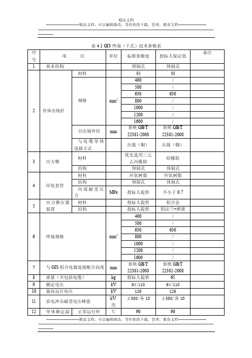
表 4.1 GIS 终端(干式)技术参数表
目
单位 标准参数值 投标人保证值
材料
预制式 铜
预制式 铜
备注
400
/
2 导体出线杆
3
应力锥
规格
mm2
引出端外径 mm 与电缆导体 连接方式 材料 结构
500 630 800 1000 1200 1600 参照 GB/T 22381-2008
压接(铜)
630
630
《用Visual-C开发GIS系统》第2章-MFC应用程序设计的开发工具PPT课件

.ቤተ መጻሕፍቲ ባይዱ
9
视化管理的工具。利用它调用AppStudio可以对 程序所拥有的各种资源(菜单、工具条、对话 框、加速键、热键等)进行可视化管理。
FileView(文件视图)是管理一个开发项目所包含 的所有文件的工具。通过它可以用来管理一个 开发项目所包含的源文件。
.
20
.
21
.
22
.
23
.
24
⑦ 在图2-7所示的MFC AppWizard-Step 5 of 6对话框中, 用户需要对是否在生成的程序源代码中加入注释进 行选择。在本例中,选择“Yes, please”(加入注释) 选项。另外有一个选项是选择在产生的应用程序中 如何应用MFC,有两种选择:“As a shared DLL”(作 为共享动态链接库)和“As a statically linked library”(作为静态链接库)。选择“As a shared DLL” 选项,单击Next按钮,就会进入图2-8所示的MFC AppWizard-Step 6 of 6对话框。
.
16
2.1.2 利用MFC AppWizard产生MFC应用程序的步骤
在这一节中,应用MFC AppWizard生成一个叫做Draw的应 用程序。以下是利用AppWizard产生MFC应用程序框架 的步骤:
首先,进入VC++的工作区,运行工作区上的“File”菜单 下的“New”命令,打开New对话框,然后进行如下步 骤的操作:
.
13
图2 AppWizard创建.框架程序对话框
14
表2-1 AppWizard创建的应用程序类型
ArcObjects-开发文档教学材料

▪ Geodatabase的实现方式主要有两种: ▪ (1)Accesss数据库 ▪ (2)ArcSDE图层
▪ Acess数据库:
▪ SDE图层:
▪ (1)图层:ArcSDE将具有共同属性项的地理要素 归为一个图层。例如,可以将不同图幅的等高线 存放在一个线状要素层中,每个数据库记录对应 一条等高线,这样有利于地理要素的存储与管理。 逻辑上,一个图层包含描述空间和属性信息的表。 空间数据存储在要素表中,一个包含空间列的表 被称为业务表(business table),业务表与要素表 以及空间索引表的集合组成一个ArcSDE图层。
一.ArcGIS体系结构
▪ 1.1ArcGIS数据
▪ Arcgis的GIS数据主要有shapefile格式, coverage格式,geodatabase格式(数据模型)。
▪ shapefile,coverage采用文件系统存储GIS数据。
▪ 所谓“智能化”,是指在Geodatabase模型中, 地理空间要素的表达较之以往的模型更接近于我 们对现实事物对象的认识和表述方式。 Geodatabase中引入了地理空间要素的行为、规 则和关系,当处理Geodatabase中的要素时,对 其基本的行为和必须满足的规则,我们无需通过 程序编码;对其特殊的行为和规则,则可以通过 要素扩展进行客户化定义。这是其它任何空间数 据模型都做不到的。而ArcSDE正是用 GeoDatabase的数据模型将海量的空间数据存储 于商用的大型关系数据库中
▪ (4)ArcSDE的数据存储:缺省情况下,ArcSDE 使用压缩的二进制格式来存储要素的集合图形, 从而可以有效的提高存储和检索空间数据的效率。 一个压缩的二进制要素类有由三个数据表组成:业 务表,要素表,空间索引表,它们之间通过空间
ARCGIS10.0中文帮助文档-官方在线帮助文档-图文版
3D 坐标系
投影坐标系也逐渐地开始使用 z 值来测量平均海平面以上或以下的高程。 在下图中,标记 (2,3,4) 所记录的点在 x 轴方向距原点两个单位,在 y 轴方向距原点三个单位 并且高程为地球表面以上四个单位(例如平均海平面以上 4 米)。
地图投影中的属性和变形
由于地球是球体,所以制图人员和 GIS 专家所要面临的一个挑战就是如何使用平面坐标系表达真 实世界。要体会这种两难的困境,只需想一想如何将半个篮球变平即可;如果不改变它的形状或创 建不连续的区域,就无法做到这一点。将地球变平的过程称为投影,由此而产生了术语地图投影。
使用直角坐标系的地图投影
投影坐标系是指用于平面(例如打印的地图或计算机屏幕)的任何坐标系。 2D 和 3D 直角坐标系都可使用 x 值和 y 值(在后面会讲到,也可使用栅格的列和行)描述要 素的地理位置和形状。 直角坐标系使用两个轴:一条水平轴 (x),表示东西方向,一条垂直轴 (y),表示南北方向。两轴 的交汇点称为原点。地理对象的位置使用 (x,y) 标记法相对于原点进行定义,其中 x 表示沿水平 轴的距离,y 表示沿垂直轴的距离。原点定义为 (0,0)。 在下图中,标记 (4,3) 所记录的点在 x 轴方向距原点四个单位,在 y 轴方向距原点三个单位。
地理信息系统 (GIS) 是以可视化和分析地理引用信息为目的, 用于描述和表征地球及其他地理现象的 一种系统。 许多人已经将 GIS 视为最强大的信息技术之一,因为它致力于整合来自多种来源的知识(例如,作 为地图中的各种图层)并创建一个跨领域的合作环境。此外,对于大多数接触过 GIS 的人们来说,
它直观易懂,具有很大的吸引力。它将强大的可视化环境(使用地图进行沟通和可视化)与基于地理 科学的稳健的分析和建模框架相结合。 这种结合孕育出一项科学、可信且易于交流(通过地图和其他地理视图)的新技术。 在您开始使用 ArcGIS 时,应了解 GIS 的一些基础知识以及在软件的使用过程中 ArcGIS 如何实 现这些理论,这一点十分重要。在本部分中,您将会了解到有关一些 GIS 重要方面以及如何依据一 系列重要地图概念构建地理信息模型的信息。
GIS技术文档

目录1. 交通运管监控平台 (2)1.1. 使用客户 (2)4.1. 主要功能 (2)4.1.1. 实时监控车辆位置信息(包括普货,危货,客运) (2)4.1.2. 在线审核 (2)4.1.3. 在线报警 (2)4.1.4. 路线监控 (2)4.1.5. 轨迹查询 (2)4.1.6. 系统设置 (3)4.1.7. 报表中心 (3)1.交通运管监控平台1.1. 使用客户2.各交通运管处3.各地市企业4.后台管理平台4.1. 主要功能4.1.1.实时监控车辆位置信息(包括普货,危货,客运)以普货,危货,客运分类,监控车辆按单位来展示。
可以随机抽查某些车,进行实时监控跟踪。
4.1.2.在线审核运管处人员即时审核企业新提交的电子路单。
审核电子路单为通过或不通过。
系统默认会给电子路单提交单位的企业负责人手机号发送短信通知审核结果。
管理员也无须时时坐电脑前,等待未审核订单。
开通短信通知。
设置待审核订单超过10条提醒管理人员即时审核。
4.1.3.在线报警车辆在线报警主要统计:超速,偏线,疲劳驾驶,设防报警运管处下属车辆违规的车辆都会即时提示。
管理人员可以单个或批量查看,处理(发送短信提醒至企业负责人)处理警情发送短信,可手动和自动可以设定:车辆某种类型,在国道/省道/高速公路上,不同的超速值4.1.4.路线监控针对危险品货车和客运车辆,可以在地图上自定义路线。
设置偏线距离。
绑定某些车辆,如果这些车辆偏离线路,将会启动报警。
4.1.5.轨迹查询遇到突发事件或核对单车行使记录,可进行详细查询。
提供全年统计和单天明细。
在地图上动画方式回放具体某一天行车路线。
4.1.6.系统设置用户修改密码4.1.7.报表中心超速分析偏线离线疲劳驾驶设防报警监控统计分析。
ArcGIS平台及开发
What
ArcGIS桌面应用程序
ArcGlobe
What
ArcGIS桌面应用程序
ArcScene
What
ArcGIS桌面应用程序
ArcScene
What
ArcGIS桌面应用程序
ArcScene与ArcGlobe之间的功能区别
What
ArcGIS桌面应用程序
扩展模块
What
罗杰•汤姆林森出席 2010年Esri中国华北区用户大会
地理学、地图学家,遥感应用与地理信息系统 专家 1920年2月28日生于江西萍乡。1941年毕 业于浙江大学史地系。1980年当选为中国科学 院学部委员(院士)。1992年当选为第三世界科 学院院士。 中国科学院遥感应用研究所名誉 所长、地理科学与资源研究所研究员。20世纪 50年代积极推动我国国家地图集的编制。60年 代倡导航空像片系列制图与计算机辅助制图。 70年代致力于开拓遥感应用,组织自然资源与 城市环境航空遥感实验。80年代负责研制我国 资源与环境信息系统国家规范,筹建资源与环 境信息系统国家重点开放实验室,设计黄河、 长江中下游洪涝灾情评估信息系统。90年代积 极参与地球信息科学、全球变化及数字地球战 略研究。代表作有《地学的探索》、六卷《石 坚文存》、《遥感地学分析》和《地理信息系 统导论》。 获国家自然科学奖二等奖2次、国 家科技进步奖一等奖、航天部科技进步奖一等 奖。
MAPGIS7二次开发入门篇C++

中地软件系列丛书MAPGIS70二次开发教程―入门篇(C++版)中地数码科技有限公司2006年4月武汉内容提要《MAPGIS70二次开发教程-入门篇( C++版)》是根据最新推出的MAPGIS70软件平台编写而成,主要介绍在VC环境下进行MAPGIS70二次开发必须具备的基础知识,通过实例程序一步步的带领大家了解和理解MAPGIS70二次开发的开发模式和开发技巧。
本书作为MAPGIS70地理信息系统系列产品配套使用手册,供使用MAPGIS70地理信息系统进行二次开发的入门用户参考。
版权所有武汉中地数码科技有限公司警告:未经武汉中地数码科技有限公司书面许可,任何单位和个人均不得以任何形式或手段复制或传播本书的任何部分。
在国家“十五”863项目的支持下,历经5年的科技攻关,由中地数码科技有限公司开发的具有完全自主版权的第一套“分布式超大型GIS平台软件MAPGIS70”已经研制成功。
MAPGIS70是属于最新的“第四代GIS”软件产品,具备“纵向多层,横向网格”的分布式体系结构,采用“面向服务”的最新设计思想,支持局域和广域网络环境下空间信息网格(SIG)的分布式计算,实现了面向空间实体及其关系的数据组织、高效海量空间数据的存储与索引、大尺度多维动态空间信息数据库、三维实体建模和分析,具有TB级空间数据处理能力、支持分布式空间信息分发与共享、网络化空间信息服务,支持Unix/Linux大型服务器,支持海量、分布式的国家空间基础设施建设。
《《MAPGIS70二次开发教程-入门篇( C++版)》是根据最新推出的MAPGIS70软件平台编写而成,主要介绍在VC环境下进行MAPGIS70二次开发必须具备的基础知识,通过实例程序一步步的带领大家了解和理解MAPGIS70二次开发的开发模式和开发技巧。
本书共分为两部分:第一部分是基于插件的应用框架开发,通过实例带领大家完成工具,视图插件制作的过程。
第二部分是基于MFC类库的应用框架开发,通过实例带领大家完成地图文档的显示编辑,空间分析功能模块的开发过程。
postgis开发文档

PostGIS ManualEdited byPaul RamseyPostGIS ManualEdited by Paul RamseyPostGIS is an extension to the PostgreSQL object-relational database system which allows GIS(Geographic Information Systems)objects to be stored in the database.PostGIS includes support for GiST-based R-Tree spatial indexes,and functions for basic analysis of GIS objects.Table of Contents1.Introduction (1)1.1.Credits (1)1.2.More Information (1)2.Installation (2)2.1.Requirements (2)2.2.PostGIS (2)2.2.1.Upgrading (3)mon Problems (4)2.3.JDBC (4)2.4.Loader/Dumper (5)3.Frequently Asked Questions (6)ing PostGIS (9)4.1.GIS Objects (9)4.1.1.Standard versus Canonical Forms (9)ing OpenGIS Standards (10)4.2.1.The SPATIAL_REF_SYS Table (10)4.2.2.The GEOMETRY_COLUMNS Table (11)4.2.3.Creating a Spatial Table (12)4.3.Loading GIS Data (13)ing SQL (13)ing the Loader (13)4.4.Retrieving GIS Data (14)ing SQL (14)ing the Dumper (15)4.5.Building Indexes (16)4.5.1.GiST Indexes (16)ing Indexes (17)plex Queries (18)4.6.1.Taking Advantage of Indexes (18)ing Mapserver (18)4.7.1.Basic Usage (19)4.7.2.Advanced Usage (20)4.7.3.Examples (21)4.8.Java Clients(JDBC) (22)4.9.C Clients(libpq) (24)4.9.1.Text Cursors (24)4.9.2.Binary Cursors (24)5.PostGIS Reference (25)5.1.OpenGIS Functions (25)5.2.Other Functions (32)iPostGIS is developed by Refractions Research Inc,as a spatial database technology research project.Refractions is a GIS and database consulting company in Victoria,British Columbia,Canada,specializing in data integration and custom software development.We plan on supporting and developingPostGIS to support a range of important GIS functionality,including full OpenGIS support,advancedtopological constructs(coverages,surfaces,networks),desktop user interface tools for viewing andediting GIS data,and web-based access tools.1.1.CreditsDave Blasby dblasby@The principal developer of PostGIS.Dave maintains the server side objects and index support,theserver side analytical functions,and the Mapserver connectivity.Chris Hodgson chodgson@Maintains new functions and the7.2index bindings.Paul Ramsey pramsey@Maintains the JDBC objects and keeps track of the documentation and packaging.Jeff Lounsbury jeffloun@Maintains the Shape loader/dumper.1.2.More Information•The latest software,documentation and news items are available at the PostGIS web site,.•More information about the PostgreSQL database server is available at the PostgreSQL main site.•More information about GiST indexing is available at the GiST development site,http://www.sai.msu.su/~megera/postgres/gist.•More information about Mapserver internet map server is available at (/).•The"Simple Features for Specification for SQL(/techno/specs/99-049.pdf)"isavailable at the OpenGIS Consortium web site:.12.1.RequirementsPostGIS has the following requirements for building and usage:•A complete configured and built PostgreSQL source code tree.PostGIS uses definitions from thePostgreSQL configure/build process to conform to the particular platform you are building on.PostgreSQL is available from .•GNU C compiler(gcc).Some other ANSI C compilers can be used to compile PostGIS,but wefindfar fewer problems when compiling with gcc.•GNU Make(gmake or make).For many systems,GNU make is the default version of make.Checkthe version by invoking make-v.Other versions of make may not process the PostGIS Makefileproperly.•(Optional)Proj4reprojection library.The Proj4library is used to provide coordinate reprojectionsupport within PostGIS.Proj4is available for download from /proj.2.2.PostGISThe PostGIS module is a extension to the PostgreSQL backend server.As such,PostGIS0.8.0requires afull copy of the PostgreSQL source tree in order to compile.The PostgreSQL source code is available at.PostGIS0.8.0can be built against PostgreSQL versions7.1.0to7.4.x.Earlier versions of PostgreSQLare not supported.1.Before you can compile the postgis server modules,you must compile and install the PostgreSQLpackage.NOTE:if you plan to use GEOS functionality you might need to link PostgreSQL against thestandard C++library:LDFLAGS=-lstdc++./configure YOUR_OPTIONS_HEREThis is a workaround for bogus C++exceptions interaction with older development tools.If youexperience weird problems(backend unexpectedly closed or similar things)try that.2.Retrieve the PostGIS source archive from /postgis-0.8.0.tar.gz.Uncompress and untar the archive in the"contrib"directory of the PostgreSQL source tree.#cd[postgresql source tree]/contrib#gzip-d-c postgis-0.8.0.tar.gz|tar xvf-3.Once your PostgreSQL installation is up-to-date,enter the"postgis"directory,and edit theMakefile.2•If you are compiling PostGIS0.7.2or earlier against PostgreSQL7.2.x,you must set theUSE_PG72variable to1.This is done automatically by newer version of postgis.•If want support for coordinate reprojection you must have the Proj4library installed,set theUSE_PROJ variable to1,and eventually adjust PROJ_DIR to point to your Proj4installationdirectory.•If want to use GEOS functionalities you must have the GEOS library installed,set the USE_GEOSvariable to1,and eventually adjust GEOS_DIR to point to your GEOS installation directory.4.Run the compile and install commands.#make#make installAllfiles are installed relative to the PostgreSQL install directory,[prefix].•Libraries are installed[prefix]/lib/contrib.•Important supportfiles such as postgis.sql are installed in[prefix]/share/contrib.•Loader and dumber binaries are installed in[prefix]/bin.5.PostGIS requires the PL/pgSQL procedural language extension.Before loading the postgis.sqlfile,you mustfirst enable PL/pgSQL.You should use the createlang command.ThePostgreSQL7.1Programmer’s Guide has the details if you want to this manually for some reason.#createlang plpgsql[yourdatabase]6.Now load the PostGIS object and function definitions into your database by loading thepostgis.sql definitionsfile.#psql-d[yourdatabase]-f postgis.sqlThe PostGIS server extensions are now loaded and ready to use.7.For a complete set of EPSG coordinate system definition identifiers,you can also load thespatial_ref_sys.sql definitionsfile and populate the SPATIAL_REF_SYS table.#psql-d[yourdatabase]-f spatial_ref_sys.sql2.2.1.UpgradingUpgrading PostGIS can be tricky,because the underlying C libraries which support the object types andgeometries may have changed between versions.To avoid problems when upgrading,you will have todump all the tables in your database,destroy the database,create a new one,execute the newpostgis.sqlfile,then upload your database dump:#pg_dump-t"*"-f dumpfile.sql yourdatabase#dropdb yourdatabase#createdb yourdatabase#createlang plpgsql yourdatabse3#psql-f postgis.sql-d yourdatabase#psql-f dumpfile.sql-d yourdatabase#vacuumdb-z yourdatabaseNote:When upgrading from version0.5to0.6+,all your geometries will be created with an SRID of-1.To create valid OpenGIS geometries,you will have to create a valid SRID in theSPATIAL_REF_SYS table,and then update your geometries to reference the SRID with the followingSQL(with the appropriate substitutions:UPDATE TABLE table SET geocolumn=SetSRID(geocolumn,SRID);mon ProblemsThere are several things to check when your installation or upgrade doesn’t go as you expected.1.It is easiest if you untar the PostGIS distribution into the contrib directory under the PostgreSQLsource tree.However,if this is not possible for some reason,you can set thePGSQL_SRC environment variable to the path to the PostgreSQL source directory.This will allowyou to compile PostGIS,but the make install may not work,so be prepared to copy thePostGIS library and executablefiles to the appropriate locations yourself.2.Check that you you have installed PostgreSQL7.1or newer,and that you are compiling against thesame version of the PostgreSQL source as the version of PostgreSQL that is running.Mix-ups canoccur when your(Linux)distrubution has already installed PostgreSQL,or you have otherwiseinstalled PostgreSQL before and forgotten about it.PostGIS will only work with PostgreSQL7.1ornewer,and strange,unexpected error messages will result if you use an older version.To check theversion of PostgreSQL which is running,connect to the database using psql and run this query:SELECT version();Also check that you have made any necessary changes to the top of the Makefile.This includes:1.Changing the USE_PG72=0line to USE_PG72=1if you are using PostgreSQL7.2or newer.If thisline is incorrect,it will result in a large number of errors being generated either when compiling,orwhen executing the sql statements in the postgis.sqlfile.2.If you want to be able to do coordinate reprojections,you must install the Proj.4library on yoursystem,set the USE_PROJ variable to1and the PROJ_DIR to your installation prefix in theMakefile.3.If you want to be able to use GEOS functions you must install the GEOS library on your system,andset the USE_GEOS to1and the GEOS_DIR to your installation prefix in the Makefile.42.3.JDBCThe JDBC extensions provide Java objects corresponding to the internal PostGIS types.These objectscan be used to write Java clients which query the PostGIS database and draw or do calculations on theGIS data in PostGIS.1.Enter the jdbc sub-directory of the PostGIS distribution.2.Edit the Makefile to provide the correct paths of your java compiler(JAVAC)and interpreter(JAVA).3.Run the make command.Copy the postgis.jarfile to wherever you keep your java libraries.2.4.Loader/DumperThe data loader and dumper are built and installed automatically as part of the PostGIS build.To buildand install them manually:#cd postgis-0.8.0/loader#make#make installThe loader is called shp2pgsql and converts ESRI Shapefiles into SQL suitable for loading inPostGIS/PostgreSQL.The dumper is called pgsql2shp and converts PostGIS tables into ESRI shapefiles.5Chapter3.Frequently Asked Questions1.What kind of geometric objects can I store?You can store point,line,polygon,multipoint,multiline,multipolygon,and geometrycollections.Theseare specified in the Open GIS Well Known Text Format(with3d extentions).2.How do I insert a GIS object into the database?First,you need to create a table with a column of type"geometry"to hold your GIS data.Connect toyour database with psql and try the following SQL:CREATE TABLE gtest(ID int4,NAME varchar(20));SELECT AddGeometryColumn(’dbname’,’gtest’,’geom’,-1,’LINESTRING’,2);If the geometry column addition fails,you probably have not loaded the PostGIS functions and objectsinto this database.See the installation instructions.Then,you can insert a geometry into the table using a SQL insert statement.The GIS object itself isformatted using the OpenGIS Consortium"well-known text"format:INSERT INTO gtest(ID,NAME,GEOM)VALUES(1,’First Geometry’,GeometryFromText(’LINESTRING(23,45,65,78)’1));For more information about other GIS objects,see the object reference.To view your GIS data in the table:SELECT id,name,AsText(geom)AS geom FROM gtest;The return value should look something like this:id|name|geom---+-----------+-------------------1|First Geometry|LINESTRING(23,45,65,78)(1row)3.How do I construct a spatial query?There are a number of spatial operators available to PostgreSQL,and several of them have beenimplemented by PostGIS in order to provide indexing support.In order to do a spatial query with index support,you must use the"overlap operator"(&&)which usesthe following important simplifying assumption:all features shall be represented by their boundingboxes.We recognize that using bounding boxes to proxy for features is a limiting assumption,but it is animportant one in providing spatial indexing mercial spatial databases use the sameassumption–bounding boxes are important to most spatial indexing schemes.The most important spatial operator from a user’s perspective is the"&&"overlap operator,which testswhether one feature’s bounding box overlaps that of another.An example of a spatial query using&&is:SELECT id,name FROM GTEST WHERE GEOM&&’BOX3D(34,45)’::box3d6Note that the bounding box used for querying must be explicitly declared as a box3d using the"::box3d"casting operation.4.How do I speed up spatial queries on large tables?Fast queries on large tables is the raison d’etre of spatial databases(along with transaction support)so having a good index in important.To build a spatial index on a table with a geometry column,use the"CREATE INDEX"function as follows:CREATE INDEX[indexname]ON[tablename]USING GIST([geometrycolumn]gist_geometry_ops);The"USING GIST"option tells the server to use a GiST(Generalized Search Tree)index.The reference to"gist_geometry_ops"tells the server to use a particular set of comparison operators for building the index:the"gist_geometry_ops"are part of the PostGIS extension.Note:For PostgreSQL version7.1.x,you can specifically request a"lossy"index by appending WITH (ISLOSSY)to the index creation command.For PostgreSQL7.2.x and above all GiST indexes are assumed to be lossy.Lossy indexes uses a proxy object(in the spatial case,a bounding box)for building the index.5.Why aren’t PostgreSQL R-Tree indexes supported?Early versions of PostGIS used the PostgreSQL R-Tree indexes.However,PostgreSQL R-Trees have been completely discarded since version0.6,and spatial indexing is provided with an R-Tree-over-GiST scheme.Our tests have shown search speed for native R-Tree and GiST to be comparable.Native PostgreSQLR-Trees have two limitations which make them undesirable for use with GIS features(note that these limitations are due to the current PostgreSQL native R-Tree implementation,not the R-Tree concept in general):•R-Tree indexes in PostgreSQL cannot handle features which are larger than8K in size.GiST indexes can,using the"lossy"trick of substituting the bounding box for the feature itself.•R-Tree indexes in PostgreSQL are not"null safe",so building an index on a geometry column which contains null geometries will fail.6.Why should I use the AddGeometryColumn()function and all the other OpenGIS stuff?If you do not want to use the OpenGIS support functions,you do not have to.Simply create tables as in older versions,defining your geometry columns in the CREATE statement.All your geometries will have SRIDs of-1,and the OpenGIS meta-data tables will not befilled in properly.However,this will7cause most applications based on PostGIS to fail,and it is generally suggested that you do use AddGeometryColumn()to create geometry tables.Mapserver is one application which makes use of the geometry_columns meta-data.Specifically, Mapserver can use the SRID of the geometry column to do on-the-fly reprojection of features into the correct map projection.7.What is the best way tofind all objects within a radius of another object?To use the database most efficiently,it is best to do radius queries which combine the radius test with a bounding box test:the bounding box test uses the spatial index,giving fast access to a subset of data which the radius test is then applied to.For example,tofind all objects with100meters of POINT(10001000)the following query would work well:SELECT*FROM GEOTABLEWHEREGEOM&&GeometryFromText(’BOX3D(900900,11001100)’,-1)ANDDistance(GeometryFromText(’POINT(10001000)’,-1),GEOM)<100;8.How do I perform a coordinate reprojection as part of a query?To perform a reprojection,both the source and destination coordinate systems must be defined in the SPATIAL_REF_SYS table,and the geometries being reprojected must already have an SRID set on them.Once that is done,a reprojection is as simple as referring to the desired destination SRID.SELECT Transform(GEOM,4269)FROM GEOTABLE;8ing PostGIS4.1.GIS ObjectsThe GIS objects supported by PostGIS are the"Simple Features"defined by the OpenGIS Consortium(OGC).Note that PostGIS currently supports the features and the representation APIs,but not the variouscomparison and convolution operators given in the OGC"Simple Features for SQL"specification.Examples of the text representations of the features are as follows:•POINT(000)•LINESTRING(00,11,12)•POLYGON((000,400,440,040,000),(110,210,220,120,110))•MULTIPOINT(000,121)•MULTILINESTRING((000,110,121),(231,321,541))•MULTIPOLYGON(((000,400,440,040,000),(110,210,220,120,110)),((-1-10,-1-20,-2-20,-2-10,-1-10)))•GEOMETRYCOLLECTION(POINT(239),LINESTRING((234,345)))Note that in the examples above there are features with both2-dimensional and3-dimensionalcoordinates.PostGIS supports both2d and3d coordinates–if you describe a feature with2Dcoordinates when you insert it,the database will return that feature to you with2D coordinates when youextract it.See the sections on the force_2d()and force_3d()functions for information on convertingfeatures to a particular coordinate dimension representation.4.1.1.Standard versus Canonical FormsThe OpenGIS specification defines two standard ways of expressing spatial objects:the Well-KnownText(WKT)form(shown in the previous section)and the Well-Known Binary(WKB)form.Both WKTand WKB include information about the type of the object and the coordinates which form the object.However,the OpenGIS specification also requires that the internal storage format of spatial objectsinclude a spatial referencing system identifier(SRID).The SRID is required when creating spatialobjects for insertion into the database.For example,a valid insert statement to create and insert a spatialobject would be:INSERT INTO SPATIALTABLE(THE_GEOM,THE_NAME)VALUES(GeometryFromText(’POINT(-126.445.32)’,312),’A Place’)Note that the"GeometryFromText"function requires an SRID number.The"canonical form"of the spatial objects in PostgreSQL is a text representation which includes all theinformation necessary to construct the object.Unlike the OpenGIS standard forms,it includes the type,coordinate,and SRID information.The canonical form is the default form returned from a SELECT9query.The example below shows the difference between the OGC standard and PostGIS canonicalforms:db=SELECT AsText(geom)AS OGCGeom FROM thetable;OGCGeom---------------------------------LINESTRING(-123.74137839304948.9124018962261,-123.74158711563948.9123981907507)(1row)db=SELECT geom AS PostGISGeom FROM thetable;PostGISGeom---------------------------------SRID=123;LINESTRING(-123.74137839304948.9124018962261,-123.74158711563948.9123981907507)(1row)ing OpenGIS StandardsThe OpenGIS"Simple Features Specification for SQL"defines standard GIS object types,the functionsrequired to manipulate them,and a set of meta-data tables.In order to ensure that meta-data remainconsistent,operations such as creating and removing a spatial column are carried out through specialprocedures defined by OpenGIS.There are two OpenGIS meta-data tables:SPATIAL_REF_SYS and GEOMETRY_COLUMNS.TheSPATIAL_REF_SYS table holds the numeric IDs and textual descriptions of coordinate systems used inthe spatial database.4.2.1.The SPATIAL_REF_SYS TableThe SPATIAL_REF_SYS table definition is as follows:CREATE TABLE SPATIAL_REF_SYS(SRID INTEGER NOT NULL PRIMARY KEY,AUTH_NAME VARCHAR(256),AUTH_SRID INTEGER,SRTEXT VARCHAR(2048),PROJ4TEXT VARCHAR(2048))The SPATIAL_REF_SYS columns are as follows:SRIDAn integer value that uniquely identifies the Spatial Referencing System within the database.AUTH_NAMEThe name of the standard or standards body that is being cited for this reference system.Forexample,"EPSG"would be a valid AUTH_NAME.AUTH_SRIDThe ID of the Spatial Reference System as defined by the Authority cited in the AUTH_NAME.Inthe case of EPSG,this is where the EPSG projection code would go.10SRTEXTThe Well-Known Text representation of the Spatial Reference System.An example of a WKT SRSrepresentation is:PROJCS["NAD83/UTM Zone10N",GEOGCS["NAD83",DATUM["North_American_Datum_1983",SPHEROID["GRS1980",6378137,298.257222101]],PRIMEM["Greenwich",0],UNIT["degree",0.0174532925199433]],PROJECTION["Transverse_Mercator"],PARAMETER["latitude_of_origin",0],PARAMETER["central_meridian",-123],PARAMETER["scale_factor",0.9996],PARAMETER["false_easting",500000],PARAMETER["false_northing",0],UNIT["metre",1]]For a listing of EPSG projection codes and their corresponding WKT representations,see/techno/interop/EPSG2WKT.TXT.For a discussion of WKT in general,seethe OpenGIS"Coordinate Transformation Services Implementation Specification"at/techno/specs.htm.PROJ4TEXTPostGIS uses the Proj4library to provide coordinate transformation capabilities.The PROJ4TEXTcolumn contains the Proj4coordinate definition string for a particular SRID.For example:+proj=utm+zone=10+ellps=clrk66+datum=NAD27+units=mFor more information about,see the Proj4web site at /proj.Thespatial_ref_sys.sqlfile contains both SRTEXT and PROJ4TEXT definitions for all EPSGprojections.4.2.2.The GEOMETRY_COLUMNS TableThe GEOMETRY_COLUMNS table definition is as follows:CREATE TABLE GEOMETRY_COLUMNS(F_TABLE_CATALOG VARCHAR(256)NOT NULL,F_TABLE_SCHEMA VARCHAR(256)NOT NULL,F_TABLE_NAME VARCHAR(256)NOT NULL,F_GEOMETRY_COLUMN VARCHAR(256)NOT NULL,COORD_DIMENSION INTEGER NOT NULL,SRID INTEGER NOT NULL,TYPE VARCHAR(30)NOT NULL)The columns are as follows:11F_TABLE_CATALOG,F_TABLE_SCHEMA,F_TABLE_NAMEThe fully qualified name of the feature table containing the geometry column.Note that the terms"catalog"and"schema"are Oracle-ish.There is not PostgreSQL analogue of"catalog"so thatcolumn is left blank–for"schema"the database name is used.F_GEOMETRY_COLUMNThe name of the geometry column in the feature table.COORD_DIMENSIONThe spatial dimension(2or3dimensional)of the column.SRIDThe ID of the spatial reference system used for the coordinate geometry in this table.It is a foreignkey reference to the SPATIAL_REF_SYS.TYPEThe type of the spatial object.To restrict the spatial column to a single type,use one of:POINT,LINESTRING,POLYGON,MULTPOINT,MULTILINESTRING,MULTIPOLYGON,GEOMETRYCOLLECTION.For heterogeneous(mixed-type)collections,you can use"GEOMETRY"as the type.Note:This attribute is(probably)not part of the OpenGIS specification,but is required forensuring type homogeneity.4.2.3.Creating a Spatial TableCreating a table with spatial data is done in two stages:•Create a normal non-spatial table.For example:CREATE TABLE ROADS_GEOM(ID int4,NAME varchar(25))•Add a spatial column to the table using the OpenGIS"AddGeometryColumn"function.The syntax is:AddGeometryColumn(db_name,table_name,column_name,srid,type,dimension).For example:SELECT AddGeometryColumn(’roads_db’,’roads_geom’,’geom’,423,’LINESTRING’,2)Here is an example of SQL used to create a table and add a spatial column(assuming the db is’parks_db’and that an SRID of128exists already):CREATE TABLE PARKS(PARK_ID int4,PARK_NAME varchar(128),PARK_DATE date,PARK_TYPE varchar(2));12SELECT AddGeometryColumn(’parks_db’,’parks’,’park_geom’,128,’MULTIPOLYGON’,2);Here is another example,using the generic"geometry"type and the undefined SRID value of-1:CREATE TABLE ROADS(ROAD_ID int4,ROAD_NAME varchar(128));SELECT AddGeometryColumn(’roads_db’,’roads’,’roads_geom’,-1,’GEOMETRY’,3);4.3.Loading GIS DataOnce you have created a spatial table,you are ready to upload GIS data to the database.Currently,thereare two ways to get data into a PostGIS/PostgreSQL database:using formatted SQL statements or usingthe Shapefile loader/dumper.ing SQLIf you can convert your data to a text representation,then using formatted SQL might be the easiest wayto get your data into PostGIS.As with Oracle and other SQL databases,data can be bulk loaded bypiping a large textfile full of SQL"INSERT"statements into the SQL terminal monitor.A data uploadfile(roads.sql for example)might look like this:BEGIN;INSERT INTO ROADS_GEOM(ID,GEOM,NAME)VALUES(1,GeometryFromText(’LINESTRING(191232243118,191108243242)’,-1),’Jeff Rd’);INSERT INTO ROADS_GEOM(ID,GEOM,NAME)VALUES(2,GeometryFromText(’LINESTRING(189141244158,189265244817)’,-1),’Geordie Rd’);INSERT INTO ROADS_GEOM(ID,GEOM,NAME)VALUES(3,GeometryFromText(’LINESTRING(192783228138,192612229814)’,-1),’Paul St’);INSERT INTO ROADS_GEOM(ID,GEOM,NAME)VALUES(4,GeometryFromText(’LINESTRING(189412252431,189631259122)’,-1),’Graeme Ave’);INSERT INTO ROADS_GEOM(ID,GEOM,NAME)VALUES(5,GeometryFromText(’LINESTRING(190131224148,190871228134)’,-1),’Phil Tce’);INSERT INTO ROADS_GEOM(ID,GEOM,NAME)VALUES(6,GeometryFromText(’LINESTRING(198231263418,198213268322)’,-1),’Dave Cres’);COMMIT;The datafile can be piped into PostgreSQL very easily using the"psql"SQL terminal monitor:psql-d[database]-f roads.sqling the LoaderThe shp2pgsql data loader converts ESRI Shapefiles into SQL suitable for insertion into aPostGIS/PostgreSQL database.The loader has several operating modes distinguished by command lineflags:-dDrops the database table before creating a new table with the data in the Shapefile.13Appends data from the Shapefile into the database table.Note that to use this option to loadmultiplefiles,thefiles must have the same attributes and same data types.-cCreates a new table and populates it from the Shapefile.This is the default mode.-DCreates a new table and populates it from the Shapefile.This uses the PostgreSQL"dump"formatfor the output data and is much faster to load than the default"insert"SQL e this for verylarge data sets.-s SRIDCreates and populates the geometry tables with the specified SRID.An example session using the loader to create an inputfile and uploading it might look like this:#shp2pgsql shaperoads roadstable roadsdb roads.sql#psql-d roadsdb-f roads.sqlA conversion and upload can be done all in one step using UNIX pipes:#shp2pgsql shaperoads roadstable roadsdb|psql-d roadsdb4.4.Retrieving GIS DataData can be extracted from the database using either SQL or the Shapefile loader/dumper.In the sectionon SQL we will discuss some of the operators available to do comparisons and queries on spatial tables.ing SQLThe most straightforward means of pulling data out of the database is to use a SQL select query anddump the resulting columns into a parsable textfile:db=#SELECT id,AsText(geom)AS geom,name FROM ROADS_GEOM;id|geom|name--+---------------------------+-------1|LINESTRING(191232243118,191108243242)|Jeff Rd2|LINESTRING(189141244158,189265244817)|Geordie Rd3|LINESTRING(192783228138,192612229814)|Paul St4|LINESTRING(189412252431,189631259122)|Graeme Ave5|LINESTRING(190131224148,190871228134)|Phil Tce6|LINESTRING(198231263418,198213268322)|Dave Cres7|LINESTRING(218421284121,224123241231)|Chris Way(6rows)However,there will be times when some kind of restriction is necessary to cut down the number offieldsreturned.In the case of attribute-based restrictions,just use the same SQL syntax as normal with anon-spatial table.In the case of spatial restrictions,the following operators are available/useful:14。
GIS技术参数【精选文档】
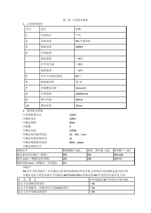
第三章专项技术规范2、通用技术参数⑴系统标称电压110kV⑵额定电压126kV⑶额定频率50Hz⑷相数 3⑸额定电流1250A⑹额定短时耐受电流31。
5kA(rms)⑺额定短路持续时间4s⑻额定峰值耐受电流80kA(peak)⑽温升GIS各个部位的温升,应不超过元件相应标准规定的允许值,主回路及无标准限定温升的元件在额定电流下的允许温升不应超过GB/T11022-2011的规定值.GIS外壳的允许温升见下表:⑾局部放电①试验应在所有绝缘试验后,在同一试品上进行。
②局部放电测量时,绝缘上的场强应尽可能与GIS完整装配后,出现在绝缘上的场强相同,单个绝缘件的放电量应不大于3pC,对一个间隔应不大于10pC。
3、断路器⑴除满足通用技术规范外,还应满足下列要求:①型式:户外、SF6气体绝缘型断路器②额定电流:1250A③额定短时耐受电流: 31.5kA(rms)④额定短路持续时间:4s⑤额定峰值耐受电流:80kA(peak)⑥关合和开断特性a合闸时间≤100msb额定全开断时间≤60msc固有分闸时间≤40msd自动重合闸无电流间隔时间0.3s及以上可调e金属短接时间≤60ms⑦三相不同期性:a合闸≤5msb分闸≤3ms⑵额定操作顺序O—0。
3s-CO-180s-CO⑶在额定操作顺序下连续开断电流而不需换气、检修的次数:①开断额定短路电流的次数≥20次②开断额定电流的次数E2级、≥5000次③机械稳定性合分循环≥10000次④不检修操作次数≥3000次⑷出线端故障的额定瞬态恢复电压特性参数:①开断电流百分数100%②首开极系数1。
5③振幅系数1。
4④恢复电压上升率 2.0kV/µs⑸开断近区故障的能力:①电源侧:3kV工频恢复电压126/开断电流百分数100%首开极系数1。
0振幅系数1。
4恢复电压上升率2。
0 kV/µs②线路侧:3kV工频恢复电压126/波阻抗450Ω峰值系数 1.6恢复电压上升率系数0.2(kV/µs)/kA③操作顺序分—0。
GIS项目开发计划书

GIS项目开发计划书项目背景GIS(地理信息系统)是一种集成了地理空间数据、地理信息处理、地理信息查询、地理信息可视化等多种功能的系统。
随着地理信息技术的发展和应用需求的增加,越来越多的组织和企业开始使用GIS项目来管理和分析地理空间数据。
本项目旨在开发一个基于GIS的应用程序,用于展示和分析地理空间数据,并提供相关的功能和服务。
首先,我们将从需求分析开始,明确项目的目标和范围;然后,进行系统设计和开发,最后进行测试和部署。
项目目标本项目的主要目标是开发一个功能完备、性能稳定的GIS应用程序,具体目标如下:1.实现地理空间数据的可视化展示,支持多种地图投影和地图样式选择;2.提供地理空间数据的查询和分析功能,如缓冲区分析、空间查询等;3.支持用户自定义数据图层的添加和编辑,方便用户管理自己的地理数据;4.实现用户权限管理和用户身份验证,保证系统安全性;5.支持多种数据格式的导入和导出,方便与其他GIS系统进行数据交换;6.提供友好的用户界面和用户操作体验,使用户能够快速上手,高效使用。
项目范围本项目的开发范围包括以下几个方面:1.前端开发:包括用户界面设计和开发、地图呈现和交互等;2.后端开发:包括数据处理和存储、查询和分析功能的实现等;3.数据库设计和管理:根据需求设计数据库结构,并进行数据库管理和优化;4.服务器部署和维护:将开发好的应用程序部署到服务器上,并进行后续的维护和升级。
开发计划本项目的开发计划分为以下几个阶段:阶段一:需求分析与设计时间:1个月在这个阶段,我们将与客户进行需求讨论,明确项目的具体需求和功能,并进行整体设计。
具体任务包括:1.与客户沟通,了解项目需求和目标;2.分析需求,提出功能设计方案;3.确定系统架构和技术选型;4.编写需求文档和设计文档。
阶段二:前端开发时间:2个月在这个阶段,我们将进行前端界面的设计和开发。
具体任务包括:1.设计用户界面,包括地图展示和地图操作的交互;2.开发地图展示功能,支持多种投影和地图样式选择;3.实现用户自定义数据图层的添加和编辑功能;4.编写前端代码,实现地图交互和数据展示。
GIS在城市土地开发强度预测中的应用PPT精品文档
3
1
距III类水质700米范围 内
2
距III类水质1000米范 围内
1
距IV类水质300米范围 内
4
距V类水质300米范围 内
4
距IV类水质500米范围 内
3
距V类水质500米范围 内
3
1
-0.5 0.5
-1 -0.5
距IV类水质700米范围 内
2
距V类水质700米范围 内
2
距IV类水质1000米范 围内
•10
•11
•12
生成距离删格结果
•13
•14
Reclassify对栅格重新分类赋值
•15
•16
•17
•18
•19
•20
•21
•22
Reclassify对栅格重新分类赋值
•23
Raster Calculator对各个因子进行计算叠加
•24
•25
•26
•27
1.3 输出排版、图例、指南针的插入
其余地区
0
其余地区
0
其余地区
0
其余地区
0
•47
2.5 宝山区发展条件判断——道路可达性
2010年
2020年
•48
2.6 宝山区发展条件判断——货运交通影响
货运交通道路
权 重
标准
赋值
距货运交通道路100米 范围内
5
距货运交通道路300米 范围内
距货运交通道路500米 范围内
距货运交通道路700米 范围内
•73
连岛视点
•74
•75
赋值
3 2 1 0
权重 1.0
滨河绿带
- 1、下载文档前请自行甄别文档内容的完整性,平台不提供额外的编辑、内容补充、找答案等附加服务。
- 2、"仅部分预览"的文档,不可在线预览部分如存在完整性等问题,可反馈申请退款(可完整预览的文档不适用该条件!)。
- 3、如文档侵犯您的权益,请联系客服反馈,我们会尽快为您处理(人工客服工作时间:9:00-18:30)。
二次开发复习
地理信息系统
以数字世界表示自然世界,具有完备的空间特征,可以存贮和处理不同发展时期的大量地理数据,并具有极强的空间系统综合分析能力,是服务于地理科学研究和应用的新技术,是地理学现代化的重要手段。
地理信息系统的功能:数据的采集与编辑、数据处理、数据的存储与组织、空间查询与分析地理信息系统设计要满足的三个基本要求:加强系统的实用性、降低系统开发和应用的成本、提高系统的生命周期
GIS开发研究的四个阶段:系统分析、系统设计(总体设计,详细设计),系统实施,系统维护和评价
结构化的基本思想:1.系统的观点(结构化的思想核心) 2.调研的观点(地理信息系统设计的基本原则) 3.结构化的观点 4.面向用户的观点
地理信息系统设计的步骤:
地理信息系统的设计:
首先需要进行大量仔细的调查工作和准备工作,其中包括了解和掌握有关部门已做了些什么,有什么文献可供参考等。
在获取大量可供使用的资料并明确系统目标的基础上,从系统观点出发,对地理事物进行分析和综合,然后才是系统的设计,具体步骤如下:
1. 系统分析(需求分析、可行性分析、业务调查、逻辑设计)
2. 系统设计(系统总体设计、模块设计、系统设计)
3. 系统实施(硬件配置、软件编制、数据准备、人员培训、系统组装、试运行和测试)
4. 系统维护(①纠错②完善和适应性维护③硬件设备的维护④数据更新)
系统评价:
就是指从技术和经济两个大的方面,对所设计的地理信息系统进行评定。
考察的主要内容有:
一、系统效率二、系统可靠性三、可扩展性四、可移植性五、系统效益
GIS开发模式:独立开发模式宿主型开发模式GIS组件开发模式
独立开发模式:
不依赖于任何GIS工具软件,从空间数据的采集、编辑到数据的处理分析及结果输出,所有的算法都由开发者独立设计,然后选用某种程序设计语言,如Visual C++、Delphi、等,在一定的操作系统平台上编程实现。
开发周期长,软件功能相对简单,对开发者要求高,用于购买软件的费用相对节省
宿主型开发模式:
基于GIS平台软件,进行应用系统开发
多数GIS平台软件都提供了可供用户进行二次开发的脚本语言,用户以原GIS软件为开发平台,利用这些脚本语言,开发出自己的针对不同应用领域的应用程序。
如ArcView中的A venue语言,MapInfo Professional的MapBasic语言
开发较为容易; 二次开发的脚本语言,功能较弱;所开发的系统不能脱离GIS平台;是解
释执行的,运行效率低;用户界面受平台软件的限制
GIS组件开发模式:
建立在组件技术基础上的GIS功能组件,实现了地理信息系统的各种功能,这些组件都具备GIS的基本功能。
开发人员可以基于通用软件开发工具,尤其是可视化开发工具,如:Delphi、Visual C++、Visual Basic、Power Builder等RAD工具为开发平台,进行二次开发,实现GIS功能。
大多数GIS软件产商都提供商业化的GIS组件。
如ESRI 公司的MapObjects、MapInfo 公司的MapX等
面向对象程序设计(OOP)
面向对象程序设计(OOP)技术汲取了结构化程序设计中好的思想,并将这些思想与一些新的、强大的理念相结合,从而给你的程序设计工作提供了一种全新的方法对象是运行期的基本实体,对象都包含数据以及操作这些数据的代码-函数或方法。
类是具有相同类型的对象的抽象。
封装是把数据和函数包装在一个单独的单元(称为类)的行为。
继承是可以让某个类型的对象获得另一个类型的对象的属性的方法。
多态的意思是事物具有不同形式的能力。
一、组件技术:
COM是组件式对象模型(Component Object Model)的英文缩写,是组件之间相互接口的规范,是OLE(Object Linking & Embedding)和ActiveX共同的基础,其作用是使各种软件构件和应用软件能够用一种统一的标准方式进行交互。
DCOM基于分布式环境下的COM被称作DCOM(Distribute COM,分布式组件对象模型)。
DCOM是ActiveX的基础,它实现了COM对象与远程计算机上的另一个对象之间直接进行交互。
ActiveX是Microsoft提出的一组基于COM(Component Object Model,组件对象模型)规范使得软件组件在网络环境中进行交互的技术集。
它与具体的编程语言无关。
一个ActiveX控件由它的一些成员组成:属性,方法以及事件
PME 模型:Property 属性Method方法Event 事件
P:属性是用来描述和反映对象特征的参数,用来保存对象的数据
M:方法是控件内部可调用的用以完成特定操作的过程或函数
E:事件是VB预先定义的,对象能识别的动作。
二、组件式GIS:
基本思想是把GIS的各大功能模块划分为几个控件,每个控件完成不同的功能。
各个GIS控件之间,以及GIS控件与其它非GIS控件之间,可以方便地通过可视化的软件开发工具集成起来,形成最终的GIS应用。
组件式GIS系统的特点:小巧灵活、价格便宜开发简捷大众化
AO 、AE 、MO 比较:
AO - ArcObjects,有上千个对象和接口,可以在其基础上开发出业界最强大的GIS
应用程序。
完全支持空间数据引擎。
但由于运行时需要安装ArcGIS核心产品和开发时用到的扩展模块产品,软件发布成本不菲,其下一代产品ArcGIS Engine则有望解决这个问题。
AE - ArcGis Engine是一个创建定制的GIS桌面应用程序的开发产品。
ArcGIS Engine 包括构建ArcGIS产品ArcV iew, ArcEditor, ArcInfo, 和ArcGIS Server.的所有核心组件。
使用ArcGIS Engine可以创建独立界面版本(stand-alone)的应用程序,或者对现有的应用程序进行扩展。
MO - MapObjects,只有十多个对象,用于简单的GIS应用程序开发,对空间数据引擎的支持度较低,但软件发布成本很低。
AO是主流,AO的分析功能比MO强,AO支持的格式更多,开发时的模式和可扩展性等等强些,也复杂多了。
MO使用简单,也很不错。
其实,如果非特别专业的要求,MO没问题的。
MO也可以连接geodatabase的,建议你采用AO,因为MO现在基本上已经没有新版本了。
AO其实是一组COM接口,适用于任何语言,如VC++,VB,DELPHI等开发语言,而MO 是一个产品。
AO不能独立存在,只要安装成功ARCGIS就可以使用AO开发,听说今后arcgis 的版本中AO可以单独发行了。
AO是AE、ArcGIS Desktop、ArcGIS Server三者的集合,按功能AO大于AE大于MO,AO面向桌面扩展开发,需要有desktop支持,不能开发出独立发布的程序AE不需要desktop 支撑,包括了AO中的大部分库,可以开发出独立发布的应用程序,MO功能简单,主要面向小型的系统开发如地图浏览,查询系统等等,或结合MIS系统运行。
AE编写的代码可以在同版本的AO环境下运行,AO环境下编写的一部分对象在AE下可能无法使用。
Mapx:
MapX是MapInfo公司的地图化的ActiveX, 在使用面向对象语言(如:VB, VC++, Delphi, PB)开发的应用中嵌入MapX可以使您的应用具有强大的地图功能.
主要对象的说明
Geoset 是地图图层及图层属性值的集合。
GeoSet 决定地图对象中放入的表的库名以及他们的设置值。
Layers, Layer 用户的数据反映在地图上通常根据点、线、面的层次结构进行归类。
每一个独立的图层都可以作为一个独立的地图。
MapX中调用的是一个由多个独立地图图层组成的地图集合。
Feature, Features, Selection 图层对象是由图形对象(Feature)集合、属性以及样式组成的。
图形对象集合(Features Object)是由多个图形对象(Feature Object)组成的Annotations 利用注释在地图上显示相应的文本或者符号。
类似与Professional 中的装饰层
Datasets 可以将外部数据与你的地图进行绑定。
Themes 专题化地图是根据特定专题普染地图的过程。