策略路由实验
配置策略路由实验
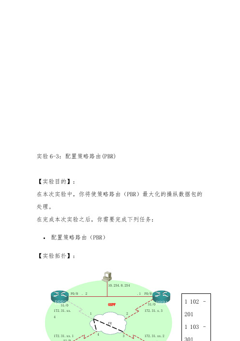
实验6-3:配置策略路由(PBR)【实验目的】:在本次实验中,你将使策略路由(PBR )最大化的操纵数据包的处理。
在完成本次实验之后,你需要完成下列任务:• 配置策略路由(PBR )【实验拓扑】:BBR2 BBR1 F0/0 . 2 .1 F0/0 10.254.0.254OSPFS1/0 S1/0 172.31.x.3 172.31.xx.1 102 –注意:图中x为所在机架编号,y为路由器编号。
【实验关心】:假如出现任何问题,能够向在值的辅导老师提出并请求提供关心。
【命令列表】:【任务一】:配置PBR配置PRB实验的目的是为了展示能够在配置任意路径中的作用,而不是路由器正常的路由选择过程。
那个实验的目的是假设你想操纵源地址为内部路由器(PxR3和PxR4)环回接口的数据包。
通常,数据包从PxR3的环回接口,走出你的实验机架,首先到达PxR1,然后是骨干路由器。
类似,数据从PxR3的环回接口,走回你的实验机架,首先到达PxR2然后是骨干路由器。
在那个实验中,你需要强制源地址为PxR3的环回接口的数据包先通过PxR1然后到达PxR2,最后达到骨干路由器。
源地址为PxR4的环回接口的数据包先通过PxR2,然后到达PxR1,最后达到骨干路由器。
实验过程:第一步:在OSPF路由配置模式下删除重分布列表。
因此BBR2将可不能拥有你的环回接口路由。
第二步:在两个边界路由器上,创建一个ACL 2去匹配直接连接的内路路由器的环回接口。
P1R1#show access-listsStandard IP access list 110 permit 10.200.200.0, wildcard bits 0.0.0.255 (10 matches)Standard IP access list 210 permit 10.1.0.0, wildcard bits 0.0.255.255 (88 matches)P1R1#第三步:在边界路由器上,PxR1和PxR2上,创建一个Route-map。
基于应用的策略路由 实验图解

策略路由实验一:基于应用的策略路由基于应用的策略路由拓扑图R1 :e0/0------R2: e0/0 网段:12.12.12.0R1 :e0/1------R2: e0/1 网段:21.21.21.0R1 :e0/3------R3: e0/0 网段:10.1.1.0R5 :e0/0------R3: e0/1 网段:172.16.1.0R2 loopback1 2.2.2.2本次实验中我们基于数据包的类型来进行策略路由,网络中的数据包类型有很多比如http telnet icmp 语音数据包等。
我们可以根据数据包的类型设置数据包的出口,在实际应用中很实用!开始本次实验(设置让http包走12.12.12.2 telnet包走21.21.21.2)R1( config)# access-list 101 permit tcp any any eq 80R1( config)# access-list 102 permit tcp any any eq 23 R1( config)#route-map xm permit 10R1( config-route-map)#match ip address 101R1( config-route-map)#set ip precedence 3R1( config-route-map)#set ip next-hop 12.12.12.2R1( config)#route-map xm permit 20R1( config-route-map)#match Ip address 102R1( config-route-map)# set ip precedence 5R1( config-route-map)# set ip next-hop 21.21.21.2 Int e0/3R1(config-if)# ip policy route-map xmR1(config)#ip local policy route-map xm配置完毕在路由器上打开debug ip policy然后r3 或r5上进行telnet 2.2.2.2 测试实验效果。
策略路由
策略路由【实验名称】策略路由Route-map【实验目的】掌握策略路由的配置(Route map)。
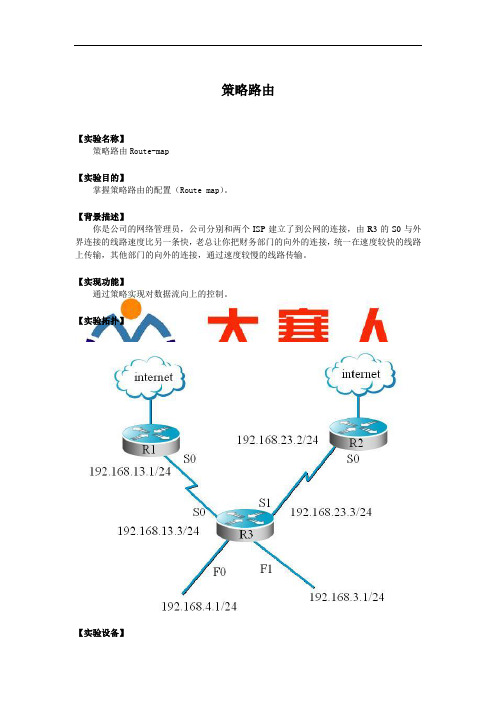
【背景描述】你是公司的网络管理员,公司分别和两个ISP建立了到公网的连接,由R3的S0与外界连接的线路速度比另一条快,老总让你把财务部门的向外的连接,统一在速度较快的线路上传输,其他部门的向外的连接,通过速度较慢的线路传输。
【实现功能】通过策略实现对数据流向上的控制。
【实验拓扑】【实验设备】实验设备R2624(3台)V35DCE(2根)、V35DTE(2根)【实验步骤】第一步:基本配置Red-Giant(config)#hos R3R3(config)#int s0R3(config-if)#ip add 192.168.13.3 255.255.255.0R3(config-if)#clock rate 64000R3(config-if)#no shR3(config-if)#int f0R3(config-if)#ip add 192.168.4.1 255.255.255.0R3(config-if)#no shR3(config)#int f1R3(config-if)#ip add 192.168.3.1 255.255.255.0R3(config-if)#no shR3(config)#int s1R3(config-if)#ip add 192.168.23.3 255.255.255.0R3(config-if)#cl ra 64000R3(config-if)#no shR3(config-if)#endRed-Giant#conf tRed-Giant(config)#hos R2R2(config)#int s0R2(config-if)#ip add 192.168.23.2 255.255.255.0R2(config-if)#no shR2(config-if)#endRed-Giant#conf tRed-Giant(config)#hos R1R1(config)#int s0R1(config-if)#ip add 192.168.13.1 255.255.255.0R1(config-if)#no shR1(config-if)#end验证测试:R1#ping 192.168.13.3Type escape sequence to abort.Sending 5, 100-byte ICMP Echoes to 192.168.13.3, timeout is 2 seconds: !!!!!R2#ping 192.168.23.3Type escape sequence to abort.Sending 5, 100-byte ICMP Echoes to 192.168.23.3, timeout is 2 seconds:!!!!!第二步:配置策略路由R3(config)#access-list 1 permit 192.168.4.0 0.0.0.255R3(config)#access-list 2 per 192.168.3.0 0.0.0.255R3(config)# route-map to-fast permit 10 ! 定义route-map 允许的流量R3(config-route-map)#mat ip address 10 !定义该route-map中调用的访问控制列表R3(config-route-map)#set ip next-hop 192.168.13.1 !定义特定网段的流向R3(config-route-map)#exiR3(config)#route-map to-slow per 10R3(config-route-map)#match ip address 20R3(config-route-map)#set ip next-hop 192.168.23.2验证测试:R3#sh route-maproute-map to-slow, permit, sequence 10Match clauses:ip address (access-lists): 2Set clauses:ip next-hop 192.168.23.2Policy routing matches: 0 packets, 0 bytesroute-map to-fast, permit, sequence 10Match clauses:ip address (access-lists): 1Set clauses:ip next-hop 192.168.13.1Policy routing matches: 0 packets, 0 bytes第三步:在接口下应用R3(config)#int s0R3(config-if)#ip policy route-map to-fast ! 在接口下应用route-mapR3(config-if)#exiR3(config)#int s1R3(config-if)#ip policy route-map to-slowR3(config-if)#end验证测试:R3#sh ip int s0Serial0 is up, line protocol is upInternet address is 192.168.13.3/24Broadcast address is 255.255.255.255Address determined by setup commandMTU is 1500 bytesHelper address is not setDirected broadcast forwarding is disabledOutgoing access list is not setInbound access list is not setProxy ARP is enabledSecurity level is defaultSplit horizon is enabledICMP redirects are always sentICMP unreachables are always sentICMP mask replies are never sentIP fast switching is enabledIP fast switching on the same interface is enabledIP multicast fast switching is enabledRouter Discovery is disabledIP output packet accounting is disabledIP access violation accounting is disabledTCP/IP header compression is disabledPolicy routing is enabled, using route map to-fast【注意事项】●在接口下应用;●控制列表要写准确,如果应用了deny,需要通过其他流量,记得末尾要用permitany 。
配置策略路由实验

02
实验环境与准备
实验设备
1 2
路由器
使用Cisco 2911型号路由器,运行IOS 15.6(4)T操作系统。
交换机
使用Cisco 3750型号交换机,运行IOS 15.6(4)T操作系统。
3
计算机
使用Windows 10操作系统,配置有双网卡, 分别连接至LAN和WAN。
实验拓扑
• 实验中采用了简单的网络拓扑,包括LAN、WAN和DMZ区 域。路由器连接WAN和Internet,交换机连接LAN和DMZ 区域,计算机位于LAN区域。
实验前的准备步骤
安装和配置Cisco IOS软件。
配置基本的网络设置,如IP地址、子网掩码和默认网 关。
连接和测试设备之间的连接性。 了解实验目标和要求,以及策略路由的工作原理。
对策略路由的进一步思考与扩展应用场景
通过本次实验,我们对策略路由有了更深入的了解,对其在 实际网络环境中的应用也有了更清晰的认识。在未来,我们 可以考虑将策略路由应用到更广泛的场景中。
例如,可以在企业网络中部署策略路由,根据不同的流量和 用户需求,实现更加灵活和高效的网络访问控制和流量调度 。此外,在数据中心、云计算等领域,策略路由也有着广泛 的应用前景。
在实验过程中,我们遇到了一些问题,例如在配置策略路由时出现了错误提示, 导致策略路由无法正常工作。经过仔细检查和排查,我们发现是因为在配置策略 路由时,有一条规则的优先级设置错误,导致其他规则无法正常生效。
为了解决这个问题,我们重新审视了策略路由的配置规则,并参考了相关文档, 最终找到了正确的解决方案。我们重新调整了规则的优先级,并成功地解决了问 题。
策略路由的实训报告

一、实训目的本次实训旨在使学生掌握策略路由的基本概念、配置方法以及在实际网络中的应用。
通过实训,使学生能够理解策略路由在路由选择中的作用,提高网络管理的效率,为以后从事网络管理工作打下基础。
二、实训环境1. 硬件设备:两台路由器(华为AR2200系列),一台服务器,一台PC。
2. 软件环境:路由器配置软件(如华为VRP),服务器操作系统(如Windows Server 2012),PC操作系统(如Windows 10)。
三、实训原理策略路由是一种路由选择方式,根据特定的策略选择最佳路由。
在路由器上,可以配置多种路由策略,如优先级、带宽、延迟等,当数据包到达路由器时,根据策略进行路由选择。
策略路由的配置步骤如下:1. 配置策略路由表:根据需要选择路由策略,如优先级、带宽等,配置路由策略表。
2. 配置路由映射:根据策略路由表,配置路由映射,将数据包映射到相应的策略。
3. 配置路由协议:使路由器能够学习到其他路由器上的路由信息。
4. 验证策略路由配置:检查策略路由是否正确配置,确保数据包按照预期路由。
四、实训过程1. 配置路由器(1)在路由器上配置IP地址、子网掩码等信息。
(2)配置路由协议,如OSPF、BGP等,使路由器能够学习到其他路由器上的路由信息。
2. 配置策略路由(1)配置策略路由表:设置优先级、带宽等策略。
(2)配置路由映射:将数据包映射到相应的策略。
3. 验证策略路由(1)在PC上发送数据包,观察数据包是否按照预期路由。
(2)检查路由器上的路由表,确认数据包是否按照策略路由表进行路由选择。
五、实训结果1. 成功配置了策略路由,实现了数据包按照预期路由。
2. 理解了策略路由的基本概念、配置方法以及在实际网络中的应用。
3. 提高了网络管理的效率,为以后从事网络管理工作打下了基础。
六、实训总结1. 策略路由是一种有效的路由选择方式,可以提高网络管理的效率。
2. 策略路由的配置需要根据实际需求进行,合理配置策略路由表和路由映射。
配置策略路由实验

配置策略路由实验汇报人:日期:•实验背景与目标•实验环境与准备•实验步骤与操作•实验数据与结果分析•实验总结与展望•参考文献与致谢01实验背景与目标背景介绍实验目标02实验环境与准备路由器交换机计算机030201实验设备实验拓扑1. 核心层:由一台Cisco 2811路由器组成,连接各个实验软件与工具03实验步骤与操作设备启动与登录基础配置设备管理配置路由器基本功能确定目标网络在路由器上指定目标网络,并设置下一跳地址,完成静态路由的配置。
配置静态路由验证配置配置策略路由规则在路由器上创建策略路由规则,并指定对应的接口或下一跳地址。
确定策略路由规则根据实际需求,确定数据包转发的规则,例如根据源IP地址、目标IP地址等因素进行匹配。
验证配置通过数据流测试,验证策略路由规则是否按照预期进行数据包转发。
04实验数据与结果分析分析不同路由策略下的数据,比较静态路由和动态路由的优劣。
分析不同负载情况下的数据,比较负载均衡和负载分担的差异。
分析不同网络流量情况下的数据,比较策略路由在不同流量情况下的表现。
通过图表展示不同网络流量情况下策略路由的吞吐量、延迟等指标。
通过图表展示不同路由策略下策略路由的可用性、稳定性等指标。
通过图表展示不同负载情况下负载均衡和负载分担的效果。
结果展示05实验总结与展望实验总结成功实现验证了理论达到预期效果规则冲突性能影响配置复杂问题与改进03应用扩展01深入研究02优化配置未来展望06参考文献与致谢[1] 张三, 李四. 策略路由实验指导书[M]. 北京: 人民邮电出版社,2020.[2] 王五, 赵六. 策略路由技术研究报告[R]. 上海: 上海交通大学,2021.[3] 刘七, 马八. 基于策略路由的流量工程优化论文[J]. 计算机学报, 2022, 45(3): 401-410.参考文献致谢感谢实验室的领导和工作人员在实验过程中的关心和支持。
THANK YOU。
策略路由与前缀列表实验
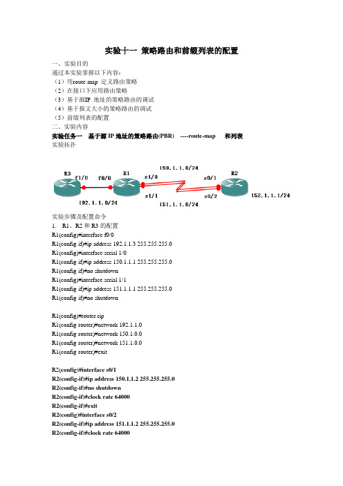
实验十一策略路由和前缀列表的配置一、实验目的通过本实验掌握以下内容:(1)用route-map 定义路由策略(2)在接口下应用路由策略(3)基于源IP 地址的策略路由的调试(4)基于报文大小的策略路由的调试(5)前缀列表的配置二、实验内容实验任务一基于源IP地址的策略路由(PBR) ----route-map 和列表实验拓扑实验步骤及配置命令1.R1、R2和R3的配置R1(config)#interface f0/0R1(config-if)#ip address 192.1.1.3 255.255.255.0R1(config)#interface serial 1/0R1(config-if)#ip address 150.1.1.1 255.255.255.0R1(config-if)#no shutdownR1(config)#interface serial 1/1R1(config-if)#ip address 151.1.1.1 255.255.255.0R1(config-if)#no shutdownR1(config)#router ripR1(config-router)#network 192.1.1.0R1(config-router)#network 150.1.0.0R1(config-router)#network 151.1.0.0R1(config-router)#exitR2(config)#interface s0/1R2(config-if)#ip address 150.1.1.2 255.255.255.0R2(config-if)#no shutdownR2(config-if)#clock rate 64000R2(config-if)#exitR2(config)#interface s0/2R2(config-if)#ip address 151.1.1.2 255.255.255.0R2(config-if)#clock rate 64000R2(config-if)#no shutdownR2(config-if)#exitR2(config)#interface loopback 0R2(config-if)#ip address 152.1.1.1 255.255.255.0R2(config-if)#exitR2(config)#router ripR2(config-router)#network 150.1.0.0R2(config-router)#network 151.1.0.0R2(config-router)#network 152.1.0.0R2(config)#do wrR3(config)#interface f1/0R3(config-if)#ip address 192.1.1.1 255.255.255.0R3(config-if)#ip address 192.1.1.2 255.255.255.0 secondary2. R1(config)#access-list 1 permit 192.1.1.1 0.0.0.0R1(config)#access-list 2 permit 192.1.1.2 0.0.0.0定义两台服务器的IPR1(config)#route-map lab1 permit 10R1(config-route-map)#match ip address 1R1(config-route-map)#set ip next-hop 150.1.1.2R1(config-route-map)#exitRoute Map表lab1的第一条语句,服务器192.1.1.1的数据经过下一跳地址是150.1.1.2即s0/1发送,条件语句嵌套ACL1R1(config)#route-map lab1 permit 20R1(config-route-map)#match ip address 2R1(config-route-map)#set ip next-hop 151.1.1.2R1(config-route-map)#exitRoute Map表lab1的第二条语句,服务器192.1.1.2的数据经过下一跳地址是151.1.1.2即s0/2发送,条件语句嵌套ACL2R1(config)#interface f 0/0R1(config-if)#ip policy route-map lab1在f 0/0接口上应用名字是lab1的Route Map表R1(config)#ip local policy route-map lab1要求路由器本身产生的数据包也接受策略路由的管理2.测试扩展的traceroute 命令R3#traceroute ipTarget IP address: 152.1.1.1Source address: 192.1.1.1Numeric display [n]:Timeout in seconds [3]:Probe count [3]:Minimum Time to Live [1]:Maximum Time to Live [30]:Port Number [33434]:Loose, Strict, Record, Timestamp, Verbose[none]: Type escape sequence to abort.Tracing the route to 152.1.1.11 150.1.1.2 56 msec * 72 msecR3#traceroute ipTarget IP address: 152.1.1.1Source address: 192.1.1.2Numeric display [n]:Timeout in seconds [3]:Probe count [3]:Minimum Time to Live [1]:Maximum Time to Live [30]:Port Number [33434]:Loose, Strict, Record, Timestamp, Verbose[none]: Type escape sequence to abort.Tracing the route to 152.1.1.11 151.1.1.2 56 msec * 52 msec另一种测试源IP地址的策略路由使用debug ip policy命令来监视策略路由R1#debug ip policyPolicy routing debugging is onR3#pingProtocol [ip]:Target IP address: 152.1.1.1Repeat count [5]:Datagram size [100]:Timeout in seconds [2]:Extended commands [n]: ySource address or interface: 192.1.1.1Type of service [0]:Set DF bit in IP header? [no]:Validate reply data? [no]:Data pattern [0xABCD]:Loose, Strict, Record, Timestamp, Verbose[none]:Sweep range of sizes [n]:Type escape sequence to abort.Sending 5, 100-byte ICMP Echos to 152.1.1.1, timeout is 2 seconds: Packet sent with a source address of 192.1.1.1!!!!!Success rate is 100 percent (5/5), round-trip min/avg/max = 4/51/128 ms 这样路由器R1会输出debug ip policy监视所得的结果,截图该命令显示定义的所有路由策略及路由策略匹配的情况。
路由策略

策略路由PBR:policy base routing 。
基于策略的路由,控制数据包实验目的:了解策略路由的应用实验拓扑:实验环境:整个Top属于OSPF area0,R1上的环回口1.1.1.1,R5上的环回口192.168.1.5和192.168.1.6,控制192.168.1.5走R3-R4-R1,控制192.168.1.6走R3-R2-R1实验配置:在R3上查看OSPF路由表,发现到1.1.1.1的路由有两条路查看配置之前1.5和1.6的路径R3:配置ACL配置策略路由,让1.5从R4走,让1.6从R2走在R5上tracert发现没有效果,在模拟器上做策略路由是没有效果的如何控制次优路径,避免环路的产生实验目的:了解route-policy的应用,了解import-route的应用实验原理:ISIS中通过tag标记来标识路由,并通过route-policy来拒绝tag,控制次优路径;ospf中通过更改cost值来控制次优路径。
实验现象:R1上只有3.3.3.3的网段为负载均衡,其他网段路由表中只有一条路由(通过route-policy 拒绝tag来控制次优路径);R3上只有1.1.1.1网段为负载均衡,其他网段路由表中只有一条路由(通过route-policy 更改cost值来控制次优路径)实验拓扑:实验环境:R1、R2、R4之间运用ISIS协议,R2、R3、R4之间运用OSPF协议。
R2和R4为level-1-2实验配置:配置基础命令:R1:配置ISIS配置ip地址,并把每个接口加入isis查看路由表R2:配置ISIS配置OSPF配置IP地址,接口g0/0/1属于ospf,其余接口属于ISIS配置完成后查看路由表,能从OSPF和ISIS学习到所有的路由条目R3:3.3.3.3作为外部路由引入配置策略路由配置ospf配置IP地址查看路由表R4:配置ISIS配置OSPF配置IP地址,G0/0/0属于OSPF,其余接口属于ISIS配置完成后查看路由表,能从OSPF和ISIS学习到所有的路由条目配置策略需要双向引入:在R2上ospf中引入isis,并做策略i-2-o;isis中引入ospf,并做策略o-2-i在R4上ospf中引入isis,并做策略i-2-o;isis中引入ospf,并做策略o-2-i配置ACL,2000作用于192.168.12.0网段的次优路径(R3上查看),2001作用于192.168.23.0网段的次优路径(R1上查看),2002作用于2.2.2.2的次优路径(R3上查看)Acl指的是对端的ip地址,若4.4.4.4控制次优路径,必须在R2上配置查看R1的路由表在没配置route-policy之前,查看R3的路由表,发现出现了次优路径。
LAB配置策略路由PBR

测试法
在配置策略路由之前和之后,分别进行网络性能测试,比较测试结果
以验证配置的效果。
结果展示与分析
性能提升
负载均衡
安全增强
灵活控制
通过策略路由的配置,网络性能 得到显著提升,响应时间缩短, 吞吐量增加。
策略路由可以实现网络流量的负 载均衡,提高网络资源利用率, 降低单台服务器的负载。
通过策略路由,可以实现网络流 量的安全控制,有效防范网络攻 击,增强网络安全性能。
网络拓扑
Lab环境
实验环境包括两个汇聚层交换机、两个接入层交换机、两个汇聚层路由器和 一个核心路由器。
网络拓扑结构
核心路由器通过汇聚层路由器与两个汇聚层交换机相连,每个汇聚层交换机 下面连接两个接入层交换机,每个接入层交换机下面连接三个PC,共计24个 PC。
02
lab配置
配置物理接口
1 2
连接性
lab配置策略路由pbr
xx年xx月xx日
目 录
• 实验环境及网络拓扑 • lab配置 • pbr实验 • 策略路由实验 • 结果验证与分析 • 总结与展望
01
实验环境及网络拓扑
实验环境
CentOS
操作系统采用CentOS,需要安装所需的网络管理工具和命 令行工具。
Vmware ESXi
虚拟化平台使用Vmware ESXi,创建虚拟机并配置网络连接 。
设备配置
网络连接配置:配置各设备之间的网络连接关系,包 括IP地址、子网掩码、网关等。
pbr配置流程
确定路由策略
明确数据包的源、目的地址和传输协议,以及相 应的路由策略。
配置策略路由
根据路由策略,配置数据包转发的下一跳地址或 传输协议。
基于策略的路由选择试验

第四章基于策略的路由选择试验三实验1配置基于源地址的策略路由【实验名称】配置基于源地址的策略路由。
【实验目的】通过实验可以理解策略在基于源地址的策略路由原理。
【背景描述】某公司网络拓补如图4-1所示,为了网络的稳定性,公司网络通过两台路由器连接到外部网络中。
为了实现更好的网络管理,网络管理员要求,IP地址为192.168.1.1~192.168.1.127的主机访问外部网络时通过路由器RB,网络中IP地址为192.168.1.128~192.168.1.254的报文转发到路由器RC的F0/0接口。
【需求分析】在路由RA上配置基于源IP地址的策略路由,可以实现将源地址为192.168.1.1~192.168.1.127的报文转发到路由器RB的Serial4/0接口,将源地址为192.168.1.128~192.168.1.254的报文转发到路由器RC的F0/0接口。
【实验拓补】【实验设备】路由器3台二层交换机1台主机3台【预备知识】在路由器RA上配置PBR,对流经端口F0/0的数据检测其源IP地址为192.168.1.1/24~192.168.1.127/24则将其发送到路由器RB的Serial4/0端口;如果源地址为192.168.1.128/24~192.168.1.254/24则将其发送到路由器RC的F0/0接口。
【实验步骤】第一步:在路由器上配置IP路由选择和IP地址RA#configure terminalRA(config)#interface serial 4/0RA(config-if)#ip address 192.168.3.1 255.255.255.0RA(config-if)#exitRA(config)#interface FastEthernet 0/0RA(config-if)#ip address 192.168.1.1 255.255.255.0RA(config-if)#exitRA(config)#interface FastEthernet 0/1RA(config -if)#ip address 192.168.4.1 255.255.255.0RA(config-if)#exitRB#configure terminalRB(config)#interface serial 4/0RB(config-if)#ip address 192.168.3.2 255.255.255.0RB(config-if)#exitRB(config)#interface FastEthernet 0/1RB(config-if)#ip address 192.168.5.1 255.255.255.0RB(config-if)#exitRC#configure terminalRC(config)#interface serial 0/0RC(config-if)#ip address 192.168.4.2 255.255.255.0RC(config-if)#exitRC(config)#interface FastEthernet 0/1RC(config-if)#ip address 192.168.5.2 255.255.255.0RC(config-if)#exit第二步:在网络中配置RIPRA(config)#router ripRA(config-router)#version 2RA(config-router)#network 192.168.1.0RA(config-router)#network 192.168.3.0RA(config-router)#network 192.168.4.0RA(config-router)#no auto-summaryRB(config)#router ripRB(config-router)#version 2RB(config-router)#network 192.168.3.0RB(config-router)#network 192.168.5.0RB(config-router)#no auto-summaryRC(config)#router ripRC(config-router)#version 2RC(config-router)#network 192.168.5.0RC(config-router)#network 192.168.4.0RC(config-router)#no auto-summary第三步:配置PBRRA(config)#access-list 10 permit 192.168.1.0 0.0.0.127RA(config)#access-list 11 permit 192.168.1.128 0.0.0.127RA(config)#router-map netbig permit 10!配置名为netbig的router-mapRA(config-router-map)#match ip address 10!匹配access-list 10的数据执行下面的动作RA(config-router-map)#set ip next-hop 192.168.3.2!设置下一条地址为192.168.3.2RA(config-router-map)#exitRA(config)#router-map netbig permit 20RA(config-router-map)#match ip address 11!匹配access-list 11的数据执行下面的动作RA(config-router-map)#set ip next-hop 192.168.4.2!设置下一条地址为192.168.4.2RA(config-router-map)#exit第四步:在报文的入站接口应用router-mapRA(config)interface fastEthernet 0/0RA(config-if)#ip policy router-map netbig第五步:验证测试在主机HostA上用tracert命令测试数据包发送路径,如图4-2所示:从tracert结果可以看到,主机HostA发送的数据包通过路由器RB进行转发。
策略路由实验报告

策略路由实验报告策略路由是一种基于策略的路由选择方式,它通过制定具体的策略来根据不同的条件选择最优的路由。
策略路由在网络管理和优化中扮演着重要的角色,能够提高网络的灵活性和可管理性。
策略路由实验是为了验证策略路由的有效性和性能,通过构建实验环境,设计一系列的实验任务并进行实测,从而得出关于策略路由的实际应用效果和其他相关指标的实验结果。
本次策略路由实验针对网络拓扑和流量分布设计了一套策略路由方案,主要包括以下几个实验任务:1. 实验环境的构建:选择适当的网络拓扑和流量模型,构建实验所需的拓扑结构,并设置合理的流量分布。
2. 策略路由的设计:根据实验的目标,制定一套合适的策略路由方案,包括路由策略的定义和配置、优先级的设置等。
3. 策略路由的实验性能评估:通过实验数据的采集和分析,评估策略路由的性能表现,包括转发延迟、带宽利用率、丢包率等指标。
4. 策略路由与其他路由方案的对比:将策略路由与其他常见的路由方案进行对比,比如静态路由、动态路由等,评估其在实验环境下的性能差距。
5. 实验结果的分析和总结:根据前面的实验数据和对比结果,分析策略路由的优越性、适用性和局限性,并对实验得出的结论进行总结和归纳。
在整个实验过程中,需要进行详细的实验设计和规划,包括实验的目标、实验环境的构建、实验参数的设置等。
同时需要注意实验过程的可重复性和可验证性,确保实验结果的准确性。
在实验过程中,还需要合理运用统计学方法和数据分析技巧,对实验数据进行处理和分析。
最后,根据实验结果和结论,可以进一步展开相关的研究工作,比如进一步改进策略路由方案、探索优化策略路由的方法等。
实验报告应当包含实验设计和原理介绍、实验结果分析和总结等内容,结合实际情况进行详细回答,完整展示实验过程和实验结果。
route-policy的配置实验总结与心得

【路由策略】的配置实验总结与心得一、实验目的1.1 了解路由策略的基本概念和作用;1.2 掌握路由策略的配置方法和步骤;1.3 探索路由策略在网络管理中的应用。
二、实验环境2.1 使用华为、思科或者Juniper等品牌的路由器搭建实验环境;2.2 准备多台主机模拟复杂网络环境。
三、实验步骤3.1 搭建实验环境;3.2 配置基本的路由策略;3.3 模拟不同网络场景,测试路由策略的效果;3.4 总结实验数据,分析路由策略在不同情况下的表现。
四、实验总结4.1 路由策略的优点和局限性;4.2 路由策略配置中的注意事项;4.3 路由策略在网络管理中的重要性;4.4 对未来路由策略发展的展望。
五、心得体会5.1 通过本次实验,我深刻理解了路由策略的概念和作用,掌握了路由策略的配置方法和步骤;5.2 在实验中遇到了一些问题,但通过不断的调整和优化,最终取得了满意的实验效果;5.3 路由策略在网络管理中起着至关重要的作用,可以根据实际需求灵活调整,提高网络的安全性和稳定性;5.4 未来,随着网络规模的不断扩大和网络安全形势的复杂化,路由策略的发展方向将更加多样化和智能化。
六、结语6.1 本次实验让我受益匪浅,对于路由策略有了更深入的了解和认识;6.2 我将继续深入学习和实践,不断提升自己在网络管理领域的能力和水平;6.3 我相信,在不久的将来,我一定能够在实际工作中充分发挥所学所用,为公司的网络安全和稳定运行贡献自己的力量。
五、心得体会5.1 本次实验让我深刻理解了路由策略的重要性和复杂性。
在配置路由策略的过程中,需要考虑网络拓扑、数据流向、安全需求等多个因素,这需要综合考虑和灵活调整,在实际应用中能够体现出其价值和作用。
5.2 在实验中,我遇到了一些问题,比如在配置路由策略时需要考虑到网络中的具体情况,包括网络流量、数据包的传输路径、安全需求等。
在实际操作中,需要仔细思考和分析,确保所配置的路由策略能够满足实际需求,提高网络的安全性和稳定性。
实验12 路由策略综合

路由策略综合实验一、路由策略综合实验拓扑图,如图1.1所示:图1.1 路由策略综合实验拓扑图二、实验要求:1.R1上重分布EIGRP100的路由进入到EIGRP125和OSPF域,发进EIGRP125要求汇总(R1 loopback 宣告进OSPF域).2.R5上一定要通过汇总路由到达EIGRP100,到达EIGRP域要优选R1这条路3.R2上单点双向重分布(保证5可以到ospf域,ospf可以到达EIGRP 125),要求发进EIGRP的时候考虑eigrp 100的明细路由(需求 2)发到OSPF 的时候要考虑那条汇总路由4.Area23要求优化LSA(考虑R2做重分布),保证R3具有可达性(R2发默认路由)5.R3重分布OSPF到RIP,保证R4可以通过OSPF到达全网(考虑R2给R3的默认路由)6.R5重分布EIGRP到RIP(思考如果R3首先重分布路由给R4,R5如何重分布EIGRP给R4)7.保证R4不存在次优路径,可以通过OSPF和EIGRP同时到达的区域,优选EIGRP三、各路由器初始配置://R1的初始配置:R1(config)#interface Loopback0R1(config-if)# ip address 172.16.0.1 255.255.255.0R1(config-if)#interface Loopback1R1(config-if)# ip address 172.16.1.1 255.255.255.0R1(config-if)#interface Loopback2R1(config-if)# ip address 172.16.2.1 255.255.255.0R1(config-if)#interface Loopback3R1(config-if)# ip address 172.16.3.1 255.255.255.0 R1(config-if)#interface Loopback4R1(config-if)# ip address 10.0.0.1 255.255.255.0 R1(config-if)#interface Loopback5R1(config-if)# ip address 1.1.1.1 255.255.255.0R1(config-if)#interface Serial2/1R1(config-if)# ip address 12.0.0.1 255.255.255.0 R1(config-if)#no shutdownR1(config-if)#interface Serial2/2R1(config-if)# ip address 15.0.0.1 255.255.255.0 R1(config-if)#no shutdown//R2的基础配置R2(config)#interface Loopback0R2(config-if)# ip address 2.2.2.2 255.255.255.0R2(config-if)#interface FastEthernet0/0R2(config-if)# ip address 25.0.0.2 255.255.255.0 R2(config-if)#no shutdownR2(config-if)#interface Serial2/1R2(config-if)# ip address 12.0.0.2 255.255.255.0 R2(config-if)# no shutdownR2(config-if)#interface Serial2/2R2(config-if)# ip address 23.0.0.2 255.255.255.0 R2(config-if)# no shutdown//R3的具体配置R3(config)#interface Loopback0R3(config-if)# ip address 3.3.3.3 255.255.255.0R3(config-if)#interface Serial2/1R3(config-if)# ip address 23.0.0.3 255.255.255.0 R3(config-if)#no shutdownR3(config-if)#interface Serial2/2R3(config-if)# ip address 34.0.0.3 255.255.255.0 R3(config-if)#no shutdown//R4的具体配置R4(config)#interface Loopback0R4(config-if)# ip address 4.4.4.4 255.255.255.0R4(config-if)#interface Serial2/1R4(config-if)# ip address 34.0.0.4 255.255.255.0 R4(config-if)# no shutdownR4(config-if)#interface Serial2/2R4(config-if)# ip address 45.0.0.4 255.255.255.0 R4(config-if)# no shutdown//R5的具体配置R5(config)#interface Loopback0R5(config-if)# ip address 5.5.5.5 255.255.255.0R5(config-if)#interface FastEthernet0/0R5(config-if)# ip address 25.0.0.5 255.255.255.0R5(config-if)#no shutdownR5(config-if)#interface Serial2/1R5(config-if)# ip address 15.0.0.5 255.255.255.0R5(config-if)# no shutdownR5(config-if)#interface Serial2/2R5(config-if)# ip address 45.0.0.5 255.255.255.0R5(config-if)# no shutdown四、实验配置:1.R1上的具体配置://开启eigrp100并激活相应网络接口R1(config-if)#router eigrp 100R1(config-router)# network 10.0.0.1 0.0.0.0R1(config-router)# network 172.16.0.0 0.0.3.255R1(config-router)# no auto-summary //关闭自动汇总//开启eigrp125,激活相应网络接口,充分发路由R1(config-router)#router eigrp 125R1(config-router)# redistribute eigrp 100//将eigrp100充分发到eigrp125R1(config-router)# network 15.0.0.1 0.0.0.0R1(config-router)# distribute-list 1 in Serial2/2//开启分布列表控制流量拒绝2.2.2.0/24和172.16.0.0/22的流量从S2/2接口进入eigrp域内R1(config-router)# no auto-summaryR1(config-router)#R1(config-router)#router ospf 1R1(config-router)# router-id 1.1.1.1R1(config-router)# redistribute eigrp 100 subnets//将eigrp100重分发进ospf1R1(config-router)# network 1.1.1.1 0.0.0.0 area 0R1(config-router)# network 12.0.0.1 0.0.0.0 area 0R1(config)#access-list 1 deny 2.2.2.0 0.0.0.255 //抓取2.2.2.0/24的流量,控制次优R1(config)#access-list 1 deny 172.16.0.0 0.0.3.255 //抓取172.16.0.0/24的流量R1(config)#access-list 1 premit any2.R2上的具体配置://在R2上开启eigrp125,并将ospf1重分发进eigrpR2(config-if)#router eigrp 125R2(config-router)#$ 1 1500 match internal nssa-external //只允许ospf内部路由和nssa外部路由重分发进入eigrp125 R2(config-router)# network 25.0.0.2 0.0.0.0R2(config-router)# distribute-list 1 in FastEthernet0/0 //控制次优路径172.16.0.0/22R2(config-router)# no auto-summaryR2(config-router)#R2(config-router)#router ospf 1R2(config-router)# router-id 2.2.2.2R2(config-router)# area 23 nssa default-information-originate //将area23设置成为nssa域并在area23里面传播默认路由R2(config-router)# redistribute eigrp 125 subnets //将eigrp125重分布进入ospf1 R2(config-router)# network 2.2.2.2 0.0.0.0 area 0R2(config-router)# network 12.0.0.2 0.0.0.0 area 0R2(config-router)# network 23.0.0.2 0.0.0.0 area 23R2(config)#access-list 1 deny 172.16.0.0 0.0.3.255 //抓取172.16.0.0/22的流量R2(config)#access-list 1 permit any3.R3上的具体配置R3(config-if)#router ospf 1R3(config-router)# router-id 3.3.3.3R3(config-router)# area 23 nssa //在R3上将area23也设置成为nssa区域R3(config-router)# network 23.0.0.3 0.0.0.0 area 23R3(config-router)#R3(config-router)#router ripR3(config-router)# version 2R3(config-router)# redistribute ospf 1 metric 5 route-map deny0//重分布ospf进入rip 并用route-map deny0控制流量,避免默认路由传入,防止环路R3(config-router)# network 3.0.0.0R3(config-router)# network 34.0.0.0R3(config-router)# no auto-summaryR3(config-router)#R3(config)#access-list 1 deny 0.0.0.0//抓取默认路由的流量R3(config)#access-list 1 permit anyR3(config)#R3(config)#route-map deny0 deny 10 //写拒绝路由映射,控制默认路由R3(config-route-map)# match ip address 14.R4上的具体配置//在R4上开启rip v2,宣告相应网络R4(config-if)#router ripR4(config-router)# version 2R4(config-router)# network 4.0.0.0R4(config-router)# network 34.0.0.0R4(config-router)# network 45.0.0.0R4(config-router)# no auto-summary5.R5上的具体配置//在R5上开启eigrp125,宣告相应网络,并将rip重分布进入其中R5(config-if)#router eigrp 125R5(config-router)# redistribute rip metric 10000 100 255 1 1500//重分布rip进eigrp R5(config-router)# network 5.0.0.0R5(config-router)# network 15.0.0.5 0.0.0.0R5(config-router)# network 25.0.0.5 0.0.0.0R5(config-router)# no auto-summary//开启rip进程,宣告相应网络,并将eigrp125重分布进入ripR5(config-router)#router ripR5(config-router)# version 2R5(config-router)# redistribute eigrp 125 metric 3 //重分布eigrp125进入rip,并将度量设置为3,选定eigrp为最优路径R5(config-router)# network 45.0.0.0R5(config-router)# no auto-summary经过以上配置以后,已经将全网互通,而且已经将次优路径剔除干净。
策略路由实验配置

实验主要步骤与配置内容
network 24.1.1.0 0.0.0.255 area 0
R3
interface Loopback0
ip address 3.3.3.3 255.255.255.0
!
interface FastEthernet0/0
r1#
r1#
r1#sho run | sec route-map
ip policy route-map AAA
route-map AAA permit 11
match ip address 1
set ip next-hop 12.1.1.2
route-map AAA permit 20
(写不完时,可另附稿纸。)
计算机类课程实验报告
院/系:网络工程课程名称:广域网技术
班级
姓名
学号
实验室号
日期
年月日
组号
计算机号
实验名称
策略路由
得分情况
一
二
三
四
五
六
成绩评定
实验内容要求
实验目的:掌握策略路由的配置(route map)。
实现功能:通过策略实现对数据流向上的控制。
实验拓扑以及IP地址规划
实现功能:通过策略使1.1.1.0网段的用户数据都通过R2向外传输,其他的通过R3向外传输。
(写不完时,可另附稿纸。)
实验主要步骤与配置内容
11.0.0.0/24 is subnetted, 1 subnets
C 11.1.1.0 is directly connected, Loopback2
配置策略路由实验

路由策略的应用场景
1 2
多出口路由
将数据包根据最佳路径或优先级路由到不同的 出口,实现负载均衡或备份。
访问控制
根据路由策略,对特定网络或应用程序进行访 问控制,防止非法访问或攻击。
3
网络隔离
通过路由策略将不同的网络隔离,以保护敏感 数据或避免网络故障影响到其他网络。
实验目的和内容
掌握路由策略的配置方法和步骤;
实验目的
旨在探究策略路由在多出口网络环境下的应用, 并分析其性能和优化方案。
实验成果
成功地实现了多个路由策略的配置和验证,在不 同场景下获得了显著的性能提升。
路由策略的进一步应用
应用场景
策略路由适用于多出口网络环境,如企业网、校园网等,可根 据实际需求进行广泛应用。
优化方向
可以考虑进一步优化策略路由的算法和参数配置,提高路由策 略的性能和稳定性。
03
技术发展
随着网络技术的不断进步,未来将会 有更多新型路由协议和算法出现,为 网络性能的提升带来更多可能性。
ANKS
谢谢您的观看
理解路由策略对网络性能和安全的影响,并能够根据 实际应用场景进行优化配置;
根据实际需求配置合理的路由策略; 通过实验验证路由策略的正确性和有效性。
02
实验环境与设备
网络拓扑结构
实验设备
3台PC、1台路由器、1台交换机
网络拓扑
PC1、PC2分别连接至交换机,交换机连接至路由器,路由器连接至Internet
提出改进意见
根据实验结果和讨论,提出相应的改进意见,如优化路由协议、增加限速等措施来提高路由策略的性能和稳定 性。
05
总结与展望
总结实验过程与成果
实验环境
计算机网络实验报告(9)路由器上配置DHCP、策略路由

一、实验项目名称路由器上配置DHCP、策略路由二、实验目的配置DHCP及完成策略路由。
三、实验设备Switch2960-24TT 1台,PC 3台,Router-PT 4台,直通线3条,交叉网线2条,串行线3条。
四、实验步骤路由器上配置DHCP:新建Packet Tracer拓扑图PC0自动获取PC1自动获取R1配置命令如下:Enconfig thost R1int f0/0ip address 192.168.10.1 255.255.255.0no shutint s1/1ip address 12.1.1.1 255.255.255.0clock rate 64000no shutexitip route 192.168.11.0 255.255.255.0 12.1.1.2R2的配置enconfig tint f0/0ip address 192.168.11.1 255.255.255.0no shutint s2/0ip address 12.1.1.2 255.255.255.0no shutexitip route 192.168.10.0 255.255.255.0 12.1.1.1R1配置ip dhcp pool zhulou //配置主楼DHCP地址池network 192.168.10.0 255.255.255.0 //动态分配192.168.10.0/24这个网段内的IP地址dns-server 218.2.135.1 //为主楼计算机配置DNS服务器default-router 192.168.10.1 //为主楼的客户机配置网关ip dhcp pool fulou //配置辅楼DHCP地址池network 192.168.11.0 255.255.255.0 //动态分配192.168.11.0/24这个网段内的IP 地址dns-server 218.2.135.1 //为辅楼计算机配置DNS服务器default-router 192.168.11.1 //为辅楼的客户机配置网关exitip dhcp excluded-address 192.168.10.1 //排除主楼客户机的网关ip dhcp excluded-address 192.168.11.1 //排除辅楼客户机的网关no ip dhcp conflict logging //不配置数据库代理R2配置(配置DHCP中继)int f0/0ip helper-address 12.1.1.1 //配置辅助寻址,指向DHCP服务器的地址,即路由器R1的IP地址最后PC0、PC1查看IP地址,如果有,则成功。
实验十二:IP策略路由
实验十二:IP策略路由一、理论基础通过设置IP策略路由,可以将不同的数据源按照管理员的要求从指定的端口流出,通过这种对数据流的策略设置,使得网络更加的有效和安全。
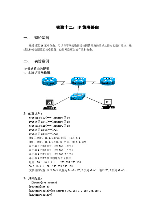
二、实验案例IP策略路由的配置1、实验拓扑结构图:2、配置说明:RouterB的S0<---> RouterA的S0Switch的E0/1<--->RouterA的E0RouterA的E1<---> RouterC的E0Switch的E0/2<--->PC1Switch的E0/3<--->PC2PC1的地址:40.1.1.2/25 网关:40.1.1.1PC2的地址:40.1.1.130/25 网关:40.1.1.129路由器B的S0地址:192.168.1.2/24路由器A的S0地址:192.168.1.1/24路由器A的E1地址:192.168.2.1/24路由器A的E0接口创建两个子接口地址: E0.1:40.1.1.1 255.255.255.128E0.2:40.1.1.129 255.255.255.128交换机的配置:端口E0/1设置为Trunk;E0/2加到VLAN2,端口E0/3加到VLAN3。
3、具体配置:[Router]sys routerB[routerB]int s0[RouterB-Serial0]ip address 192.168.1.2 255.255.255.0[RouterB-Serial0]%10:41:22: Line protocol ip on the interface Serial0 is UP 路由器B启动RIP协议:[routerB]ripwaiting...RIP is running[routerB-rip]network all[routerB-rip]dis curNow create configuration...Current configurationversion 1.74sysname routerBfirewall enableaaa-enableaaa accounting-scheme optionalinterface Aux0async mode flowlink-protocol pppinterface Ethernet0interface Serial0link-protocol pppip address 192.168.1.2 255.255.255.0interface Serial1link-protocol pppinterface Serial2link-protocol pppquitripnetwork allquit保存配置:[routerB]saveNow writing the running config to flash memory.Please wait for a while......write the running config to flash memory successfullyreturn给路由器A的S0接口加地址:192.168.1.1/24[Router]sys routerA[routerA]int s0[routerA-Serial0]ip address 192.168.1.1 255.255.255.0 [routerA-Serial0]%10:56:26: Line protocol ip on the interface Serial0 is UP 给路由器A的E1接口加地址:192.168.2.1/24[routerA]int e1[routerA-Ethernet1]ip address 192.168.2.1 255.255.255.0 [routerA-Ethernet1]%11:00:26: Line protocol ip on the interface Ethernet1 is UP 给路由器A的E0接口创建两个子接口并加地址:[routerA]int e0.1[routerA-Ethernet0.1]vlan-type dot1q vid 2[routerA-Ethernet0.1]ip address 40.1.1.1 255.255.255.128 [routerA-Ethernet0.1]%11:04:26: Line protocol ip on the interface Ethernet0.1 is UP [routerA-Ethernet0.1]int e0.2[routerA-Ethernet0.2]vlan-type dot1q vid 3[routerA-Ethernet0.2]ip address 40.1.1.129 255.255.255.128 [routerA-Ethernet0.2]%11:05:20: Line protocol ip on the interface Ethernet0.2 is UP [routerA]rip[routerA-rip]network all[routerA]dis curNow create configuration...Current configurationversion 1.74sysname routerAfirewall enableaaa-enableaaa accounting-scheme optionalinterface Aux0async mode flowlink-protocol pppinterface Ethernet0interface Ethernet0.1vlan-type dot1q vid 2ip address 40.1.1.1 255.255.255.128interface Ethernet0.2vlan-type dot1q vid 3ip address 40.1.1.129 255.255.255.128interface Ethernet1ip address 192.168.2.1 255.255.255.0interface Serial0clock DTECLK1link-protocol pppip address 192.168.1.1 255.255.255.0interface Serial1link-protocol pppinterface Serial2link-protocol pppinterface Serial3link-protocol pppquitripnetwork allquitreturn交换机的配置:接口1为干道:端口2加到VLAN2;端口3加到VLAN3[Quidway]vlan 2[Quidway-vlan2]vlan 3[Quidway-vlan3]port e0/3[Quidway-vlan3]vlan 2[Quidway-vlan2]port e0/2[Quidway]int e0/1[Quidway-Ethernet0/1]port link-type trunk[Quidway-Ethernet0/1]port trunk permit vlan allPlease wait........................................... Done. [Quidway]dis cursysname Quidwayradius scheme systemserver-type huaweiprimary authentication 127.0.0.1 1645primary accounting 127.0.0.1 1646user-name-format without-domaindomain systemradius-scheme systemaccess-limit disablestate activevlan-assignment-mode integeridle-cut disableself-service-url disablemessenger time disabledomain default enable systemlocal-server nas-ip 127.0.0.1 key huaweiqueue-scheduler wrr 1 2 4 8vlan 1vlan 2vlan 3interface Vlan-interface3interface Aux0/0interface Ethernet0/1port link-type trunkport trunk permit vlan allinterface Ethernet0/2port access vlan 2interface Ethernet0/3port access vlan 3interface Ethernet0/4interface Ethernet0/5interface Ethernet0/6interface Ethernet0/7interface Ethernet0/8interface NULL0user-interface aux 0user-interface vty 0 4return[Quidway]quit<Quidway>saveThis will save the configuration in the flash memory.The switch configurations will be written to flash.Are you sure?[Y/N]yNow saving current configuration to flash memory.Please wait for a while...Current configuration saved to flash memory successfully.[routerA]acl 2008[routerA-acl-2008]rule normal permit source 40.1.1.0 0.0.0.127 Rule has been added to normal packet-filtering rules[routerA-acl-2008]rule normal deny source anyRule has been added to normal packet-filtering rules[routerA]acl 2009[routerA-acl-2009]rule normal permit source 40.1.1.128 0.0.0.127 Rule has been added to normal packet-filtering rules[routerA-acl-2009]rule normal deny source anyRule has been added to normal packet-filtering rules[RouterA] route-policy aaa permit 10[RouterA-route-policy] if-match ip address 2008[RouterA-route-policy] apply interface S0[RouterA] route-policy aaa permit 20[RouterA-route-policy] if-match ip address 2009[RouterA-route-policy] apply interface e1[RouterA-ethernet0] ip policy route-policy aaa三、实验总结在RouterA上做策略路由,从PC1来的40.1.1.0/25的报文被送往S0口,从PC2来的40.1.1.128/25的报文被送往E1。
配置策略路由实验

实验总结
配置策略路由的重要 性
通过本次实验,我们深刻认识到配置 策略路由对于提高网络性能、增强网 络安全性以及实现业务需求的重要性 。
实验中遇到的问题及 解决方案
在实验过程中,我们遇到了一些问题 ,如路由环路、性能瓶颈等,但通过 相应的技术手段成功地解决了这些问 题。
实验经验教训
我们总结了一些经验教训,如在配置 策略路由时应充分考虑网络拓扑结构 、路由协议选择以及数据流向等因素 。
策略路由的应用场景
企业网络
企业可以根据业务需求,配置策略路由,确保关 键业务的数据流能够得到优先处理,提高企业生 产效率。
云数据中心
云数据中心通过配置策略路由,可以优化数据传 输路径,提高数据传输速度,确保云服务的可用 性和可靠性。
大型ISP网络
大型ISP可以根据地域、网络拓扑结构和客户的需 求,配置策略路由,提高网络性能和用户体验。
05
实验分析与总结
实验分析
策略路由的配置过程
在本实验中,我们通过分析网络拓扑结构、规划IP地址、配置路由器和交换机等步骤,成功地实现了策略路由的配置。
路由协议的运行机制
我们分析了各种路由协议(如RIP、OSPF和BGP)的运行机制,以及它们在策略路由中的重要作用。
数据包流转与路由选择
我们还深入研究了数据包如何在路由器之间流转,以及策略路由如何根据配置的规则对数据包进行路由选择。
EIGRP (Enhanced Interior Gateway Routing Protocol):一种增强版的IGRP协 议,是Cisco专有的路由协议,它结合了链路状态和距离向量两种路由算法的优 点。
路由表
路由表是路由器用来进行路由决策的关键数据结构,它保存 了前往各个网络的最优路径。
网络设备安装与调试chp26策略路由实验指导
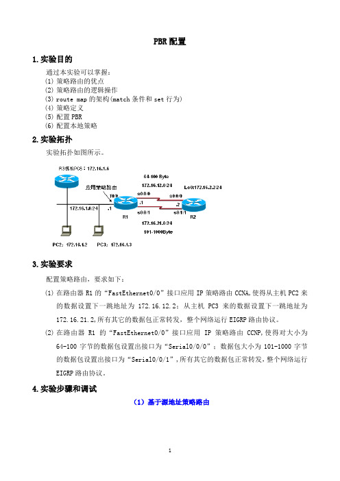
PBR配置1.实验目的通过本实验可以掌握:(1)策略路由的优点(2)策略路由的逻辑操作(3)route map的架构(match条件和set行为)(4)策略定义(5)配置PBR(6)配置本地策略2.实验拓扑实验拓扑如图所示。
3.实验要求配置策略路由,要求如下:(1)在路由器R1的“FastEthernet0/0”接口应用IP策略路由CCNA,使得从主机PC2来的数据设置下一跳地址为172.16.12.2;从主机PC3来的数据设置下一跳地址为172.16.21.2,所有其它的数据包正常转发,整个网络运行EIGRP路由协议。
(2)在路由器R1的“FastEthernet0/0”接口应用IP策略路由CCNP,使得对大小为64-100字节的数据包设置出接口为“Serial0/0/0”;数据包大小为101-1000字节的数据包设置出接口为“Serial0/0/1”,所有其它的数据包正常转发,整个网络运行EIGRP路由协议。
4.实验步骤和调试(1)基于源地址策略路由R1(config)#interface Serial0/0R1(config-if)# ip address 172.16.12.1 255.255.255.0R1(config-if)# clock rate 128000R1(config-if)#no shutR1(config-if)#exitR1(config)#interface Serial0/1R1(config-if)# ip address 172.16.21.1 255.255.255.0R1(config-if)# clock rate 128000R1(config-if)#no shutR1(config-if)#exitR1(config)#interface FastEthernet1/0R1(config-if)# ip address 172.16.1.1 255.255.255.0R1(config-if)# ip policy route-map CCNA //一个接口只能应用一个策略R1(config-if)#no shutR1(config-if)#exitR1(config)#router eigrp 1R1(config-router)# network 172.16.1.1 0.0.0.0R1(config-router)# network 172.16.12.1 0.0.0.0R1(config-router)# network 172.16.21.1 0.0.0.0R1(config-router)# no auto-summaryR1(config-router)#exitR1(config)#access-list 3 permit 172.16.1.3R1(config)#access-list 4 permit 172.16.1.4R1(config)#route-map CCNA permit 10R1(config-route-map)# match ip address 3R1(config-route-map)# set ip next-hop 172.16.12.2R1(config-route-map)#exitR1(config)#route-map CCNA permit 20R1(config-route-map)# match ip address 4R1(config-route-map)# set ip precedence criticalR1(config-route-map)# set ip next-hop 172.16.21.2R1(config-route-map)#exitR2(config-if)# ip address 172.16.2.2 255.255.255.0R2(config-if)#exitR2(config)#interface Serial0/0R2(config-if)# ip address 172.16.12.2 255.255.255.0R2(config-if)#no shutR2(config-if)#exitR2(config)#interface Serial0/3R2(config-if)# ip address 172.16.21.2 255.255.255.0R2(config-if)#no shutR2(config-if)#exitR2(config)#router eigrp 1R2(config-router)# network 172.16.2.2 0.0.0.0R2(config-router)# network 172.16.12.2 0.0.0.0R2(config-router)# network 172.16.21.2 0.0.0.0R2(config-router)# no auto-summaryR3(config-if)#ip add 172.16.1.3 255.255.255.0R3(config-if)#no shR3(config-if)#exitR3(config)#no ip routingR3(config)#ip default-gateway 172.16.1.1R4(config-if)#ip add 172.16.1.4 255.255.255.0R4(config-if)#no shR4(config-if)#exitR4(config)#no ip routingR4(config)#ip default-gateway 172.16.1.1route-map CCNA, permit, sequence 10Match clauses:ip address (access-lists): 3Set clauses:ip next-hop 172.16.12.2Policy routing matches: 5 packets, 570 bytesroute-map CCNA, permit, sequence 20Match clauses:ip address (access-lists): 4Set clauses:ip precedence criticalip next-hop 172.16.21.2Policy routing matches: 5 packets, 570 bytes----------------------------------------------------------------- R1#show ip policyInterface Route mapFa1/0 CCNAR1#debug ip policyPolicy routing debugging is on从R3上ping 172.16.2.2*Mar 1 00:10:20.095: IP: s=172.16.1.3 (FastEthernet1/0), d=172.16.2.2, len 100, FIB policy match*Mar 1 00:10:20.095: IP: s=172.16.1.3 (FastEthernet1/0), d=172.16.2.2, g=172.16.12.2, len 100, FIB policy routed*Mar 1 00:10:20.203: IP: s=172.16.1.3 (FastEthernet1/0), d=172.16.2.2, len 100, FIB policy match*Mar 1 00:10:20.203: IP: s=172.16.1.3 (FastEthernet1/0), d=172.16.2.2, g=172.16.12.2, len 100, FIB policy routed*Mar 1 00:10:20.307: IP: s=172.16.1.3 (FastEthernet1/0), d=172.16.2.2, len 100, FIB policy match*Mar 1 00:10:20.307: IP: s=172.16.1.3 (FastEthernet1/0), d=172.16.2.2, g=172.16.12.2, len 100, FIB policy routedR1#*Mar 1 00:10:20.407: IP: s=172.16.1.3 (FastEthernet1/0), d=172.16.2.2, len 100, FIB policy match*Mar 1 00:10:20.411: IP: s=172.16.1.3 (FastEthernet1/0), d=172.16.2.2, g=172.16.12.2, len 100, FIB policy routed*Mar 1 00:10:20.503: IP: s=172.16.1.3 (FastEthernet1/0), d=172.16.2.2, len 100, FIB policy match*Mar 1 00:10:20.503: IP: s=172.16.1.3 (FastEthernet1/0), d=172.16.2.2, g=172.16.12.2, len 100, FIB policy routed从R4上ping 172.16.2.2*Mar 1 00:11:05.343: IP: s=172.16.1.4 (FastEthernet1/0), d=172.16.2.2, len 100, FIB policy match*Mar 1 00:11:05.343: IP: s=172.16.1.4 (FastEthernet1/0), d=172.16.2.2, g=172.16.21.2, len 100, FIB policy routed*Mar 1 00:11:05.467: IP: s=172.16.1.4 (FastEthernet1/0), d=172.16.2.2, len 100, FIB policy match*Mar 1 00:11:05.467: IP: s=172.16.1.4 (FastEthernet1/0), d=172.16.2.2, g=172.16.21.2, len 100, FIB policy routed*Mar 1 00:11:05.575: IP: s=172.16.1.4 (FastEthernet1/0), d=172.16.2.2, len 100, FIB policy match*Mar 1 00:11:05.575: IP: s=172.16.1.4 (FastEthernet1/0), d=172.16.2.2, g=172.16.21.2, len 100, FIB policy routedR1#*Mar 1 00:11:05.663: IP: s=172.16.1.4 (FastEthernet1/0), d=172.16.2.2, len 100, FIB policy match*Mar 1 00:11:05.667: IP: s=172.16.1.4 (FastEthernet1/0), d=172.16.2.2, g=172.16.21.2, len 100, FIB policy routed*Mar 1 00:11:05.763: IP: s=172.16.1.4 (FastEthernet1/0), d=172.16.2.2, len 100, FIB policy match*Mar 1 00:11:05.763: IP: s=172.16.1.4 (FastEthernet1/0), d=172.16.2.2, g=172.16.21.2, len 100, FIB policy routed将R3接口地址改为172.16.1.5,然后ping 172.16.2.2*Mar 1 00:12:07.667: IP: s=172.16.1.5 (FastEthernet1/0), d=172.16.2.2, len 100, FIB policy rejected(no match) - normal forwarding*Mar 1 00:12:07.807: IP: s=172.16.1.5 (FastEthernet1/0), d=172.16.2.2, len 100, FIB policy rejected(no match) - normal forwarding*Mar 1 00:12:07.899: IP: s=172.16.1.5 (FastEthernet1/0), d=172.16.2.2, len 100, FIB policy rejected(no match) - normal forwarding*Mar 1 00:12:08.007: IP: s=172.16.1.5 (FastEthernet1/0), d=172.16.2.2, len 100, FIB policy rejected(no match) - normal forwarding*Mar 1 00:12:08.119: IP: s=172.16.1.5 (FastEthernet1/0), d=172.16.2.2, len 100, FIB policy rejected(no match) - normal forwarding不匹配策略的时候,正常转发数据包(2)基于数据包长度的策略路由R1(config)#route-map CCNP permit 10R1(config-route-map)# match length 64 100R1(config-route-map)# set interface Serial0/0R1(config-route-map)#exitR1(config)#R1(config)#route-map CCNP permit 20R1(config-route-map)# match length 101 1000R1(config-route-map)# set interface Serial0/1R1(config-route-map)#exitR1(config)#interface FastEthernet1/0R1(config-if)# ip policy route-map CCNP=========================================================R3#ping 172.16.2.2 size 80 repeat 1R1显示信息:*Mar 1 00:53:01.687: IP: s=172.16.1.5 (FastEthernet1/0), d=172.16.2.2, len 80, FIB policy match*Mar 1 00:53:01.687: IP: s=172.16.1.5 (FastEthernet1/0), d=172.16.2.2 (Serial0/0), len 80, FIB policy routedR3#ping 172.16.2.2 size 500 repeat 1R1显示信息:*Mar 1 00:54:26.095: IP: s=172.16.1.5 (FastEthernet1/0), d=172.16.2.2, len 500, FIB policy match*Mar 1 00:54:26.095: IP: s=172.16.1.5 (FastEthernet1/0), d=172.16.2.2 (Serial0/1), len 500, FIB policy routedR3#ping 172.16.2.2 size 1500 repeat 1R1显示信息:*Mar 1 00:55:12.739: IP: s=172.16.1.5 (FastEthernet1/0), d=172.16.2.2, len 1500, FIB policy rejected(no match) - normal forwardingR1#show route-map CCNProute-map CCNP, permit, sequence 10Match clauses:length 64 100Set clauses:interface Serial0/0Policy routing matches: 6 packets, 564 bytesroute-map CCNP, permit, sequence 20Match clauses:length 101 1000Set clauses:interface Serial0/1Policy routing matches: 6 packets, 3084 bytes(3)基于应用策略路由R1(config)#ip access-list extended HTTPR1(config-ext-nacl)# permit tcp any any eq wwwR1(config-ext-nacl)#exitR1(config)#ip access-list extended TELNETR1(config-ext-nacl)# permit tcp any any eq telnetR1(config-ext-nacl)#exitR1(config)#route-map CCIE permit 10R1(config-route-map)# match ip address HTTPR1(config-route-map)# set ip next-hop 172.16.12.2R1(config-route-map)#exitR1(config)#route-map CCIE permit 20R1(config-route-map)# match ip address TELNETR1(config-route-map)# set ip next-hop 172.16.21.2R1(config-route-map)#exitR1(config)#interface FastEthernet1/0R1(config-if)# ip address 172.16.1.1 255.255.255.0R1(config-if)# ip policy route-map CCIER1(config-if)#exitR1(config)#R1(config)#ip local policy route-map CCIE //定义本地策略R2(config)#line vty 0 4R2(config-line)#privilege level 15R2(config-line)#no loginR1显示信息:*Mar 1 01:06:41.167: IP: s=172.16.1.5 (FastEthernet1/0), d=172.16.2.2, len 43, FIB policy match*Mar 1 01:06:41.167: IP: s=172.16.1.5 (FastEthernet1/0), d=172.16.2.2, g=172.16.21.2, len 43, FIB policy routedR3#telnet 172.16.2.2 80R1显示信息:*Mar 1 01:07:43.091: IP: s=172.16.1.5 (FastEthernet1/0), d=172.16.2.2, len 44, FIB policy match*Mar 1 01:07:43.091: IP: s=172.16.1.5 (FastEthernet1/0), d=172.16.2.2, g=172.16.12.2, len 44, FIB policy routedR3#ping 172.16.2.2 repeat 1R1显示信息*Mar 1 01:08:38.183: IP: s=172.16.1.5 (FastEthernet1/0), d=172.16.2.2, len 100, FIB policy rejected(no match) - normal forwardingR1# show route-map CCIEroute-map CCIE, permit, sequence 10Match clauses:ip address (access-lists): HTTPSet clauses:ip next-hop 172.16.12.2Policy routing matches: 17 packets, 1020 bytesroute-map CCIE, permit, sequence 20Match clauses:ip address (access-lists): TELNETSet clauses:ip next-hop 172.16.21.2Policy routing matches: 16 packets, 966 bytes。
- 1、下载文档前请自行甄别文档内容的完整性,平台不提供额外的编辑、内容补充、找答案等附加服务。
- 2、"仅部分预览"的文档,不可在线预览部分如存在完整性等问题,可反馈申请退款(可完整预览的文档不适用该条件!)。
- 3、如文档侵犯您的权益,请联系客服反馈,我们会尽快为您处理(人工客服工作时间:9:00-18:30)。
策略路由修订版一:实验拓扑:二:实验要求:来自网络1.1.1..0/24,去往R4的数据流转发到R5.来自网络1.1.2.0/24,去往R4的数据流转发到R3.三:实验步骤:R1#interface Loopback0ip address1.1.1.1255.255.255.0interface Loopback1ip address1.1.2.1255.255.255.0interface Serial2/1ip address12.0.0.1255.255.255.0router eigrp100network0.0.0.0R2#interface Loopback2ip address2.2.2.2255.255.255.0interface FastEthernet0/0ip address25.0.0.2255.255.255.0interface Serial2/1ip address12.0.0.2255.255.255.0ip policy route-map ISP//在入接口上调用策略interface Serial2/2ip address23.0.0.2255.255.255.0router eigrp100network0.0.0.0access-list1permit1.1.1.00.0.0.255//用访问控制列表抓取路由access-list2permit1.1.2.00.0.0.255route-map ISP permit10//定义策略路由名称和策略号match ip address1//匹配抓取的路由set ip next-hop25.0.0.5//设置策略route-map ISP permit20match ip address2set ip next-hop23.0.0.3R3#interface Loopback0ip address3.3.3.3255.255.255.0 interface Serial2/1ip address23.0.0.3255.255.255.0 interface Serial2/2ip address34.0.0.3255.255.255.0 router eigrp100network0.0.0.0R4#interface Loopback0ip address4.4.4.4255.255.255.0 interface Serial2/1ip address34.0.0.4255.255.255.0 interface Serial2/2ip address45.0.0.4255.255.255.0 router eigrp100network0.0.0.0R5#interface Loopback0ip address5.5.5.5255.255.255.0 interface FastEthernet0/0ip address25.0.0.5255.255.255.0 interface Serial2/2ip address45.0.0.5255.255.255.0 router eigrp100network0.0.0.0实验测试:R1#trProtocol[ip]:Target IP address:4.4.4.4Source address:1.1.1.1Numeric display[n]:Timeout in seconds[3]:Probe count[3]:Minimum Time to Live[1]:Maximum Time to Live[30]:Port Number[33434]:Loose,Strict,Record,Timestamp,Verbose[none]: Type escape sequence to abort.Tracing the route to4.4.4.4112.0.0.2104msec136msec76msec225.0.0.5200msec100msec36msec345.0.0.4248msec*352msecR1#trProtocol[ip]:Target IP address:4.4.4.4Source address:1.1.2.1Numeric display[n]:Timeout in seconds[3]:Probe count[3]:Minimum Time to Live[1]:Maximum Time to Live[30]:Port Number[33434]:Loose,Strict,Record,Timestamp,Verbose[none]: Type escape sequence to abort.Tracing the route to4.4.4.4112.0.0.256msec164msec284msec223.0.0.3172msec444msec272msec334.0.0.4220msec284msec*//看到效果了吧?^-^实验完毕!实验总结:1:用访问控制列表抓取路由2:定义策略路由名称和策略号3:匹配抓取的路由4:设置策略5:在入接口上调用策略//例如本次实验access-list1permit1.1.1.00.0.0.255//用访问控制列表抓取路由access-list2permit1.1.2.00.0.0.255route-map ISP permit10//定义策略路由名称和策略号match ip address1//匹配抓取的路由set ip next-hop25.0.0.5//设置策略ip policy route-map ISP//在入接口上调用策略路由策略R4(s1/1)-(s1/0)R5R4(config)#int s1/145.0.0.44255.255.255.0R4(config-if)#ip address45.0.0.R4(config-if)#int lo0R4(config-if)#ip add4.4.4.4255.255.255.0R4(config)#router ospf100R4(config-router)#net4.4.4.00.0.0.255a0R4(config-router)#net45.0.0.00.0.0.255a0R5(config)#int s1/0R5(config-if)#ip address45.0.0.5255.255.255.0R5(config-if)#int lo0R5(config-if)#ip add5.5.5.5255.255.255.0R5(config)#router ospf100R5(config-router)#net5.5.5.00.0.0.255a0R5(config-router)#net45.0.0.00.0.0.255a0R4#show ip route4.0.0.0/24is subnetted,1subnetsC 4.4.4.0is directly connected,Loopback05.0.0.0/32is subnetted,1subnetsO 5.5.5.5[110/65]via45.0.0.5,00:00:54,Serial1/145.0.0.0/24is subnetted,1subnetsC45.0.0.0is directly connected,Serial1/1R5#show ip route4.0.0.0/32is subnetted,1subnetsO 4.4.4.4[110/65]via45.0.0.4,00:01:37,Serial1/05.0.0.0/24is subnetted,1subnetsC 5.5.5.0is directly connected,Loopback045.0.0.0/24is subnetted,1subnetsC45.0.0.0is directly connected,Serial1/0现在开始做路由策略R5(config-router)#distribute-list1in Serial1/0R5(config)#access-list1permit0.0.0.0//仅允许0.0.0.0,其他一律拒绝R5#show ip route5.0.0.0/24is subnetted,1subnetsC 5.5.5.0is directly connected,Loopback045.0.0.0/24is subnetted,1subnetsC45.0.0.0is directly connected,Serial1/0R4#show ip route4.0.0.0/24is subnetted,1subnetsC 4.4.4.0is directly connected,Loopback05.0.0.0/32is subnetted,1subnetsO 5.5.5.5[110/65]via45.0.0.5,00:00:03,Serial1/145.0.0.0/24is subnetted,1subnetsC45.0.0.0is directly connected,Serial1/1路由策略看到了吧,R5上从s1/0接口过来的路由都被丢弃.但R4可以学习到R5上的路由条目.路由原理小实验实验目标:理解路由原理.在不配置任何路由协议的情况下全网能不能互通?如果能,请说明理由.一:实验拓扑:二:基本配置:R1(config-)#int s1/1R1(config-if)#ip add12.0.0.1255.255.0.0R1(config-if)#no shR2(config-)#int s1/0R2(config-if)#ip add12.0.0.2255.255.255.0R2(config-if)#no shR2(config-if)#int s1/1R2(config-if)#ip add12.0.1.2255.255.255.0R2(config-if)#no shR1(config-)#int s1/0R1(config-if)#ip add12.0.1.3255.255.0.0R1(config-if)#no sh三:调试信息:R1#ping12.0.1.3Type escape sequence to abort.Sending5,100-byte ICMP Echos to12.0.1.3,timeout is2seconds:!!!!!Success rate is100percent(5/5),round-trip min/avg/max=372/461/640ms R1#show ip routeCodes:C-connected,S-static,R-RIP,M-mobile,B-BGPD-EIGRP,EX-EIGRP external,O-OSPF,IA-OSPF inter areaN1-OSPF NSSA external type1,N2-OSPF NSSA external type2E1-OSPF external type1,E2-OSPF external type2i-IS-IS,su-IS-IS summary,L1-IS-IS level-1,L2-IS-IS level-2ia-IS-IS inter area,*-candidate default,U-per-user static routeo-ODR,P-periodic downloaded static routeGateway of last resort is not set12.0.0.0/16is subnetted,1subnetsC12.0.0.0is directly connected,Serial1/1R2#show ip routeCodes:C-connected,S-static,R-RIP,M-mobile,B-BGPD-EIGRP,EX-EIGRP external,O-OSPF,IA-OSPF inter areaN1-OSPF NSSA external type1,N2-OSPF NSSA external type2E1-OSPF external type1,E2-OSPF external type2i-IS-IS,su-IS-IS summary,L1-IS-IS level-1,L2-IS-IS level-2ia-IS-IS inter area,*-candidate default,U-per-user static routeo-ODR,P-periodic downloaded static routeGateway of last resort is not set12.0.0.0/24is subnetted,2subnetsC12.0.0.0is directly connected,Serial1/0C12.0.1.0is directly connected,Serial1/1R3#show ip routeCodes:C-connected,S-static,R-RIP,M-mobile,B-BGPD-EIGRP,EX-EIGRP external,O-OSPF,IA-OSPF inter areaN1-OSPF NSSA external type1,N2-OSPF NSSA external type2E1-OSPF external type1,E2-OSPF external type2i-IS-IS,su-IS-IS summary,L1-IS-IS level-1,L2-IS-IS level-2ia-IS-IS inter area,*-candidate default,U-per-user static routeo-ODR,P-periodic downloaded static routeGateway of last resort is not set12.0.0.0/16is subnetted,1subnetsC12.0.0.0is directly connected,Serial1/0R1,R2,R3上的路由表信息R1R2R312.0.0.0/1612.0.0.0/2412.0.0.0/1612.0.1.0/24R3#traceroute12.0.0.1Type escape sequence to abort.Tracing the route to12.0.0.1112.0.1.2684msec680msec288msec 212.0.0.1576msec1368msec432msec R1#traceroute12.0.1.3Type escape sequence to abort.Tracing the route to12.0.1.3112.0.0.2132msec528msec288msec 212.0.1.3568msec536msec*^-^,看到了吧,中间起了个桥接作用.再看一个也可以通,路径刚好相反!个性失控工作室By:Robot4/29/2008 R1(s1/1)-(s1/0)R2(s1/1)-(s1/0)R3一:基本配置R1(config)#int lo0R1(config-if)#ip address1.1.1.1255.255.255.0R1(config-if)#no shR1(config-if)#int s1/1R1(config-if)#ip add12.0.0.1255.255.255.0R1(config-if)#no shR2(config)#int lo0R2(config-if)#ip address2.2.2.2255.255.255.0R2(config-if)#no shR2(config-if)#int s1/0R2(config-if)#ip add12.0.0.2255.255.255.0R2(config-if)#no shR2(config-if)#int s1/1R2(config-if)#ip add23.0.0.2255.255.255.0R2(config-if)#no shR3(config)#int lo0R3(config-if)#ip address3.3.3.3255.255.255.0R3(config-if)#no shR3(config-if)#int s1/0R3(config-if)#ip add23.0.0.3255.255.255.0R3(config-if)#no shR1(config)#router ripR1(config-router)#version2R1(config-router)#network1.0.0.0R1(config-router)#network12.0.0.0R2(config)#router ripR2(config-router)#version2R2(config-router)#network12.0.0.0R2(config-router)#redistribute ospf100metric3R2(config)#router ospf100R2(config-router)#net23.0.0.00.0.0.255a0R2(config-router)#net2.2.2.00.0.0.255a0R2(config-router)#redistribute rip metric3subnetsR3(config)#int s1/0R3(config-if)#ip add23.0.0.3255.255.255.0R3(config-if)#no shR3(config-if)#int lo0R3(config-if)#ip add3.3.3.3255.255.255.0R3(config)#router ospf100R3(config-router)#net23.0.0.00.0.0.255a0R3(config-router)#net3.3.3.00.0.0.255a0R1#show ip route1.0.0.0/24is subnetted,1subnetsC 1.1.1.0is directly connected,Loopback0R 2.0.0.0/8[120/3]via12.0.0.2,00:00:09,Serial1/1R 3.0.0.0/8[120/3]via12.0.0.2,00:00:09,Serial1/1R23.0.0.0/8[120/3]via12.0.0.2,00:00:09,Serial1/112.0.0.0/24is subnetted,1subnetsC12.0.0.0is directly connected,Serial1/1R2#show ip routeR 1.0.0.0/8[120/1]via12.0.0.1,00:00:11,Serial1/02.0.0.0/24is subnetted,1subnetsC 2.2.2.0is directly connected,Loopback03.0.0.0/32is subnetted,1subnetsO 3.3.3.3[110/65]via23.0.0.3,00:30:22,Serial1/123.0.0.0/24is subnetted,1subnetsC23.0.0.0is directly connected,Serial1/112.0.0.0/24is subnetted,1subnetsC12.0.0.0is directly connected,Serial1/0R3#show ip routeO E21.0.0.0/8[110/3]via23.0.0.2,00:30:31,Serial1/02.0.0.0/32is subnetted,1subnetsO 2.2.2.2[110/65]via23.0.0.2,00:30:31,Serial1/03.0.0.0/24is subnetted,1subnetsC 3.3.3.0is directly connected,Loopback023.0.0.0/24is subnetted,1subnetsC23.0.0.0is directly connected,Serial1/012.0.0.0/24is subnetted,1subnetsO E212.0.0.0[110/3]via23.0.0.2,00:30:31,Serial1/0R2#show ip ospf neighborNeighbor ID Pri State Dead Time Address Interface 23.0.0.30FULL/-00:00:3723.0.0.3Serial1/1R3#show ip ospf databaseOSPF Router with ID(23.0.0.3)(Process ID100)Router Link States(Area0)Link ID ADV Router Age Seq#Checksum Link count 2.2.2.2 2.2.2.219810x8000000B0x0083A1323.0.0.323.0.0.31030x8000000A0x00D33D3Type-5AS External Link StatesLink ID ADV Router Age Seq#Checksum Tag1.0.0.02.2.2.22050x800000020x00F1B5012.0.0.0 2.2.2.22050x800000020x00623A0Type escape sequence to abort.Tracing the route to3.3.3.3112.0.0.2260msec656msec576msec223.0.0.3720msec1680msec576msecR1#ping3.3.3.3Type escape sequence to abort.Sending5,100-byte ICMP Echos to3.3.3.3,timeout is2seconds:!!!!!Success rate is100percent(5/5),round-trip min/avg/max=576/790/1276msR2#debug ip ospf eventsOSPF events debugging is onR2#*Apr2923:05:10.111:OSPF:Rcv hello from23.0.0.3area0from Serial1/123.0.0.3*Apr2923:05:10.111:OSPF:End of hello processingR2#*Apr2923:05:16.051:OSPF:Send hello to224.0.0.5area0on Serial1/1from23.0.0.2 R2#*Apr2923:05:20.255:OSPF:Rcv hello from23.0.0.3area0from Serial1/123.0.0.3*Apr2923:05:20.255:OSPF:End of hello processingR2#*Apr2923:05:26.051:OSPF:Send hello to224.0.0.5area0on Serial1/1from23.0.0.2R2#*Apr2923:05:30.135:OSPF:Rcv hello from23.0.0.3area0from Serial1/123.0.0.3 *Apr2923:05:30.135:OSPF:End of hello processingR2#*Apr2923:05:36.051:OSPF:Send hello to224.0.0.5area0on Serial1/1from23.0.0.2 R2#*Apr2923:05:40.123:OSPF:Rcv hello from23.0.0.3area0from Serial1/123.0.0.3 *Apr2923:05:40.123:OSPF:End of hello processingR2#*Apr2923:05:46.051:OSPF:Send hello to224.0.0.5area0on Serial1/1from23.0.0.2 R2#*Apr2923:05:50.115:OSPF:Rcv hello from23.0.0.3area0from Serial1/123.0.0.3 *Apr2923:05:50.115:OSPF:End of hello processingR2#*Apr2923:05:56.051:OSPF:Send hello to224.0.0.5area0on Serial1/1from23.0.0.2 R2#*Apr2923:06:00.115:OSPF:Rcv hello from23.0.0.3area0from Serial1/123.0.0.3 *Apr2923:06:00.115:OSPF:End of hello processingR2#*Apr2923:06:06.051:OSPF:Send hello to224.0.0.5area0on Serial1/1from23.0.0.2 R2#*Apr2923:06:10.131:OSPF:Rcv hello from23.0.0.3area0from Serial1/123.0.0.3 *Apr2923:06:10.131:OSPF:End of hello processingR2#*Apr2923:06:16.051:OSPF:Send hello to224.0.0.5area0on Serial1/1from23.0.0.2 R2#*Apr2923:06:20.091:OSPF:Rcv hello from23.0.0.3area0from Serial1/123.0.0.3 *Apr2923:06:20.091:OSPF:End of hello processingR2#*Apr2923:06:26.051:OSPF:Send hello to224.0.0.5area0on Serial1/1from23.0.0.2 R2#*Apr2923:06:30.083:OSPF:Rcv hello from23.0.0.3area0from Serial1/123.0.0.3 *Apr2923:06:30.083:OSPF:End of hello processingR3#debug ip ospf eventsOSPF events debugging is onR3#*Apr2923:06:09.887:OSPF:Send hello to224.0.0.5area0on Serial1/0from23.0.0.3 R3#*Apr2923:06:15.819:OSPF:Rcv hello from2.2.2.2area0from Serial1/023.0.0.2*Apr2923:06:15.819:OSPF:End of hello processingR3#*Apr2923:06:19.887:OSPF:Send hello to224.0.0.5area0on Serial1/0from23.0.0.3 R3#*Apr2923:06:25.855:OSPF:Rcv hello from2.2.2.2area0from Serial1/023.0.0.2*Apr2923:06:25.855:OSPF:End of hello processingR3#*Apr2923:06:29.887:OSPF:Send hello to224.0.0.5area0on Serial1/0from23.0.0.3 R3#*Apr2923:06:35.835:OSPF:Rcv hello from2.2.2.2area0from Serial1/023.0.0.2*Apr2923:06:35.835:OSPF:End of hello processingR3#*Apr2923:06:39.887:OSPF:Send hello to224.0.0.5area0on Serial1/0from23.0.0.3 R3#*Apr2923:06:45.831:OSPF:Rcv hello from2.2.2.2area0from Serial1/023.0.0.2*Apr2923:06:45.835:OSPF:End of hello processingR3#*Apr2923:06:49.887:OSPF:Send hello to224.0.0.5area0on Serial1/0from23.0.0.3 R3#*Apr2923:06:55.819:OSPF:Rcv hello from2.2.2.2area0from Serial1/023.0.0.2*Apr2923:06:55.819:OSPF:End of hello processingR3#*Apr2923:06:59.887:OSPF:Send hello to224.0.0.5area0on Serial1/0from23.0.0.3 R3#*Apr2923:07:05.823:OSPF:Rcv hello from2.2.2.2area0from Serial1/023.0.0.2*Apr2923:07:05.823:OSPF:End of hello processingR3#*Apr2923:07:09.887:OSPF:Send hello to224.0.0.5area0on Serial1/0from23.0.0.3 R3#*Apr2923:07:15.843:OSPF:Rcv hello from2.2.2.2area0from Serial1/023.0.0.2*Apr2923:07:15.843:OSPF:End of hello processingR3#*Apr2923:07:19.887:OSPF:Send hello to224.0.0.5area0on Serial1/0from23.0.0.3 R3#*Apr2923:07:25.835:OSPF:Rcv hello from2.2.2.2area0from Serial1/023.0.0.2*Apr2923:07:25.835:OSPF:End of hello processingR3#*Apr2923:07:29.887:OSPF:Send hello to224.0.0.5area0on Serial1/0from23.0.0.3 R3#*Apr2923:07:35.839:OSPF:Rcv hello from2.2.2.2area0from Serial1/023.0.0.2*Apr2923:07:35.839:OSPF:End of hello processingR3#*Apr2923:07:39.887:OSPF:Send hello to224.0.0.5area0on Serial1/0from23.0.0.3 R3#*Apr2923:07:45.827:OSPF:Rcv hello from2.2.2.2area0from Serial1/023.0.0.2*Apr2923:07:45.827:OSPF:End of hello processing。