步进电机简介stepper motors
步进电机基本参数
步进电机基本参数步进电机(Stepper Motor)是一种将电脑数字信号转变为机械运动的设备,它以离散的方式旋转,每一次脉冲驱动会引起电机一定的运动。
步进电机具有以下几个基本参数。
1. 步数(Step):步进电机的运动是以步为单位的,一步表示电机转动一定的角度或线性距离。
步数也可以用来描述电机的分辨率,即每转多少步,电机转一圈。
通常情况下,步进电机的步数会在说明书或型号参数中给出。
2. 相数(Phase):步进电机的绕组分为几个相,每相两个线圈。
常见的步进电机相数有两相、三相和五相等,不同相数的步进电机在控制方式上有所不同,包括驱动方式和控制电路。
3.驱动方式:步进电机的驱动方式包括全步驱动和半步驱动。
全步驱动是每个脉冲都使电机转动一个步进角度,半步驱动是在全步的基础上细分每一步,在一个脉冲内实现小角度的运动。
半步驱动可以提高电机的分辨率和运动平滑度。
4. 转矩(Torque):步进电机的转矩是指电机产生的旋转力矩。
转矩大小与电机的结构、驱动方式和电流有关,通常在电机的规格表中有相关的数据。
5. 电流(Current):步进电机电流是指电机所需工作电流。
电机的电流大小与驱动方式、负载情况有关。
一般情况下,为了保证电机正常运行,需要匹配合适的电流驱动器。
6. 驱动电压(Voltage):步进电机的驱动电压是指驱动电机所需的电压。
电机的驱动电压应该与驱动器供电电压相匹配。
7. 最大速度(Maximum Speed):步进电机的最大速度是指电机能够达到的最高旋转速度。
最大速度与电机的结构、驱动方式、驱动电压和电流有关。
除了上述基本参数,还有一些其他的参数也需要考虑,比如电机的精度、响应时间、机械惯性等。
这些参数在具体应用中会根据实际需求进行选择和调整。
总的来说,步进电机的基本参数包括步数、相数、驱动方式、转矩、电流、驱动电压和最大速度等。
这些参数决定了电机的性能和适用范围,需要根据具体应用需求进行选择和配置。
步进电机-英文资料及翻译(Stepping Motor Types)

Stepping Motor TypesIntroductionStepping motors come in two varieties, permanent magnet and variable reluctance (there are also hybrid motors, which are indistinguishable from permanent magnet motors from the controller's point of view). Lacking a label on the motor, you can generally tell the two apart by feel when no power is applied. Permanent magnet motors tend to "cog" as you twist the rotor with your fingers, while variable reluctance motors almost spin freely (although they may cog slightly because of residual magnetization in the rotor). You can also distinguish between the two varieties with an ohmmeter. Variable reluctance motors usually have three (sometimes four) windings, with a common return, while permanent magnet motors usually have two independent windings, with or without center taps. Center-tapped windings are used in unipolar permanent magnet motors.Stepping motors come in a wide range of angular resolution. The coarsest motors typically turn 90 degrees per step, while high resolution permanent magnet motors are commonly able to handle 1.8 or even 0.72 degrees per step. With an appropriate controller, most permanent magnet and hybrid motors can be run in half-steps, and some controllers can handle smaller fractional steps or microsteps.For both permanent magnet and variable reluctance stepping motors, if just one winding of the motor is energised, the rotor (under no load) will snap to a fixed angle and then hold that angle until the torque exceeds the holding torque of the motor, at which point, the rotor will turn, trying to hold at each successive equilibrium point.Variable Reluctance MotorsFigure 1.1If your motor has three windings, typically connected as shown in the schematic diagram in Figure 1.1, with one terminal common to all windings, it is most likely a variable reluctance stepping motor. In use, the common wire typically goes to the positive supply and the windings are energized in sequence.The cross section shown in Figure 1.1 is of 30 degree per step variable reluctance motor. The rotor in this motor has 4 teeth and the stator has 6 poles, with each winding wrapped around two opposite poles. With winding number 1 energised, the rotor teeth marked X are attracted to this winding's poles. If the current through winding 1 is turned off and winding 2 is turned on, the rotor will rotate 30 degrees clockwise so that the poles marked Y line up with the poles marked 2.To rotate this motor continuously, we just apply power to the 3 windings in sequence. Assuming positive logic, where a 1 means turning on the current through a motor winding, the following control sequence will spin the motor illustrated in Figure 1.1 clockwise 24 steps or 2 revolutions:Winding 1 1001001001001001001001001Winding 2 0100100100100100100100100Winding 3 0010010010010010010010010 time --->The section of this tutorial on Mid-Level Control provides details on methods for generating such sequences of control signals, while the section on Control Circuits discusses the power switching circuitry needed to drive the motor windings from such control sequences.There are also variable reluctance stepping motors with 4 and 5 windings, requiring 5 or 6 wires. The principle for driving these motors is the same as that for the three winding variety, but it becomes important to work out the correct order to energise the windings to make the motor step nicely.The motor geometry illustrated in Figure 1.1, giving 30 degrees per step, uses the fewest number of rotor teeth and stator poles that performs satisfactorily. Using more motor poles and more rotor teeth allows construction of motors with smaller step angle. Toothed faces on each pole and a correspondingly finely toothed rotor allows for step angles as small as a few degrees.Unipolar MotorsFigure 1.2Unipolar stepping motors, both Permanent magnet and hybrid stepping motors with 5 or 6 wires are usually wired as shown in the schematic in Figure 1.2, with a center tap on each of two windings. In use, the center taps of the windings are typically wired to the positive supply, and the two ends of each winding are alternately grounded to reverse the direction of the field provided by that winding.The motor cross section shown in Figure 1.2 is of a 30 degree per step permanent magnet or hybrid motor -- the difference between these two motor types is not relevant at this level of abstraction. Motor winding number 1 is distributed between the top and bottom stator pole, while motor winding number 2 is distributed between the left and right motor poles. The rotor is a permanent magnet with 6 poles, 3 south and 3 north, arranged around its circumfrence.For higher angular resolutions, the rotor must have proportionally more poles. The 30 degree per step motor in the figure is one of the most common permanent magnet motor designs, although 15 and 7.5 degree per step motors are widely available. Permanent magnet motors with resolutions as good as 1.8 degrees per step are made, and hybrid motors are routinely built with 3.6 and 1.8 degrees per step, with resolutions as fine as 0.72 degrees per step available.As shown in the figure, the current flowing from the center tap of winding 1 to terminal a causes the top stator pole to be a north pole while the bottom stator pole is a south pole. This attracts the rotor into the position shown. If the power to winding 1 is removed and winding 2 is energised, the rotor will turn 30 degrees, or one step.To rotate the motor continuously, we just apply power to the two windings in sequence. Assuming positive logic, where a 1 means turning on the current through a motor winding, the following two control sequences will spin the motor illustrated in Figure 1.2 clockwise 24 steps or 2 revolutions:Winding 1a 1000100010001000100010001Winding 1b 0010001000100010001000100Winding 2a 0100010001000100010001000Winding 2b 0001000100010001000100010 time --->Winding 1a 1100110011001100110011001Winding 1b 0011001100110011001100110Winding 2a 0110011001100110011001100Winding 2b 1001100110011001100110011 time --->Note that the two halves of each winding are never energized at the same time. Both sequences shown above will rotate a permanent magnet one step at a time. The top sequence only powers one winding at a time, as illustrated in the figure above; thus, it uses less power. The bottom sequence involves powering two windings at a time and generally produces a torque about 1.4 times greater than the top sequence while using twice as much power.The section of this tutorial on Mid-Level Control provides details on methods for generating such sequences of control signals, while the section on Control Circuits discusses the power switching circuitry needed to drive the motor windings from such control sequences.The step positions produced by the two sequences above are not the same; as a result, combining the two sequences allows half stepping, with the motor stopping alternately at the positions indicated by one or the other sequence. The combined sequence is as follows:Winding 1a 11000001110000011100000111Winding 1b 00011100000111000001110000Winding 2a 01110000011100000111000001Winding 2b 00000111000001110000011100time --->Bipolar MotorsFigure 1.3Bipolar permanent magnet and hybrid motors are constructed with exactly the same mechanism as is used on unipolar motors, but the two windings are wired more simply, with no center taps. Thus, the motor itself is simpler but the drive circuitry needed to reverse the polarity of each pair of motor poles is more complex. The schematic in Figure 1.3 shows how such a motor is wired, while the motor cross section shown here is exactly the same as the cross section shown in Figure 1.2.The drive circuitry for such a motor requires an H-bridge control circuit for each winding; these are discussed in more detail in the section on Control Circuits. Briefly, an H-bridge allows the polarity of the power applied to each end of each winding to be controlled independently. The control sequences for single stepping such a motor are shown below, using + and - symbols to indicate the polarity of the power applied to each motor terminal:Terminal 1a +---+---+---+--- ++--++--++--++--Terminal 1b --+---+---+---+- --++--++--++--++Terminal 2a -+---+---+---+-- -++--++--++--++-Terminal 2b ---+---+---+---+ +--++--++--++--+ time --->Note that these sequences are identical to those for a unipolar permanent magnet motor, at an abstract level, and that above the level of the H-bridge power switching electronics, the control systems for the two types of motor can be identical.Note that many full H-bridge driver chips have one control input to enable the output and another to control the direction. Given two such bridge chips, one per winding, the following control sequences will spin the motor identically to the control sequences given above:Enable 1 1010101010101010 1111111111111111Direction 1 1x0x1x0x1x0x1x0x 1100110011001100Enable 2 0101010101010101 1111111111111111Direction 2 x1x0x1x0x1x0x1x0 0110011001100110 time --->To distinguish a bipolar permanent magnet motor from other 4 wire motors, measure the resistances between the different terminals. It is worth noting that some permanent magnet stepping motors have 4 independent windings, organized as two sets of two. Within each set, if the two windings are wired in series, the result can be used as a high voltage bipolar motor. If they are wired in parallel, the result can be used as a low voltage bipolar motor. If they are wired in series with a center tap, the result can be used as a low voltage unipolar motor. Bifilar MotorsBifilar windings on a stepping motor are applied to the same rotor and stator geometry as a bipolar motor, but instead of winding each coil in the stator with a single wire, two wires are wound in parallel with each other. As a result, the motor has 8 wires, not four.In practice, motors with bifilar windings are always powered as either unipolar or bipolar motors. Figure 1.4 shows the alternative connections to the windings of such a motor.Figure 1.4To use a bifilar motor as a unipolar motor, the two wires of each winding are connected in series and the point of connection is used as a center-tap. Winding 1 in Figure 1.4 is shown connected this way.To use a bifilar motor as a bipolar motor, the two wires of each winding are connected either in parallel or in series. Winding 2 in Figure 1.4 is shown with a parallel connection; this allows low voltage high-current operation. Winding 1 in Figure 1.4 is shown with a series connection; if the center tap is ignored, this allows operation at a higher voltage and lower current than would be used with the windings in parallel.It should be noted that essentially all 6-wire motors sold for bipolar use are actually wound using bifilar windings, so that the external connection that serves as a center tap is actually connected as shown for winding 1 in Figure 1.4. Naturally, therefore, any unipolar motor may be used as a bipolar motor at twice the rated voltage and half the rated current as is given on the nameplate.The question of the correct operating voltage for a bipolar motor run as a unipolar motor, or for a bifilar motor with the motor windings in series is not as trivial as it might first appear. There are three issues: The current carrying capacity of the wire, cooling the motor, and avoiding driving the motor's magnetic circuits into saturation. Thermal considerations suggest that, if the windings are wired in series, the voltage should only be raised by the square root of 2. The magnetic field in the motor depends on the number of ampere turns; when the two half-windings are run in series, the number of turns is doubled, but because a well-designed motor has magnetic circuits that are close to saturation when the motor is run at its rated voltage and current, increasing the number of ampere-turns does not make the field any stronger. Therefore, when a motor is run with the two half-windings in series, the current should be halved in order to avoid saturation; or, in other words, the voltage across the motor winding should be the same as it was.For those who salvage old motors, finding an 8-wire motor poses a challenge! Which of the 8 wires is which? It is not hard to figure this out using an ohm meter, an AC volt meter, and a low voltage AC source. First, use the ohm meter to identify the motor leads that are connected to each other through the motor windings. Then, connect a low-voltage AC source to one of these windings. The AC voltage should be below the advertised operating voltage of the motor; voltages under 1 volt are recommended. The geometry of the magnetic circuits of the motor guarantees that the two wires of a bifilar winding will be strongly coupled for AC signals, while there should be almost no coupling to the other two wires. Therefore, probing with an AC volt meter should disclose which of the other three windings is paired to the winding under power. Multiphase MotorsFigure 1.5A less common class of permanent magnet or hybrid stepping motor is wired with all windings of the motor in a cyclic series, with one tap between each pair ofwindings in the cycle, or with only one end of each motor winding exposed while the other ends of each winding are tied together to an inaccessible internal connection. In the context of 3-phase motors, these configurations would be described as Delta and Y configurations, but they are also used with 5-phase motors, as illustrated in Figure 1.5. Some multiphase motors expose all ends of all motor windings, leaving it to the user to decide between the Delta and Y configurations, or alternatively, allowing each winding to be driven independently.Control of either one of these multiphase motors in either the Delta or Y configuration requires 1/2 of an H-bridge for each motor terminal. It is noteworthy that 5-phase motors have the potential of delivering more torque from a given package size because all or all but one of the motor windings are energised at every point in the drive cycle. Some 5-phase motors have high resolutions on the order of 0.72 degrees per step (500 steps per revolution).Many automotive alternators are built using a 3-phase hybrid geometry with either a permanent magnet rotor or an electromagnet rotor powered through a pair of slip-rings. These have been successfully used as stepping motors in some heavy duty industrial applications; step angles of 10 degrees per step have been reported.With a 5-phase motor, there are 10 steps per repeat in the stepping cycle, as shown below:Terminal 1 +++-----+++++-----++Terminal 2 --+++++-----+++++---Terminal 3 +-----+++++-----++++Terminal 4 +++++-----+++++-----Terminal 5 ----+++++-----+++++-time --->With a 3-phase motor, there are 6 steps per repeat in the stepping cycle, as shown below:Terminal 1 +++---+++---Terminal 2 --+++---+++-Terminal 3 +---+++---++time --->Here, as in the bipolar case, each terminal is shown as being either connected to the positive or negative bus of the motor power system. Note that, at each step, only one terminal changes polarity. This change removes the power from one winding attached to that terminal (because both terminals of the winding in question are of the same polarity) and applies power to one winding that was previously idle. Given the motor geometry suggested by Figure 1.5, this control sequence will drive the motor through two revolutions.To distinguish a 5-phase motor from other motors with 5 leads, note that, if the resistance between two consecutive terminals of the 5-phase motor is R, the resistance between non-consecutive terminals will be 1.5R.Note that some 5-phase motors have 5 separate motor windings, with a total of 10 leads. These can be connected in the star configuration shown above, using 5 half-bridge driver circuits, or each winding can be driven by its own full-bridge. While the theoretical component count of half-bridge drivers is lower, the availability of integrated full-bridge chips may make the latter approach preferable.步进电机•介绍•变磁阻电机•单极电机•双极电机•单一电机•多相电机介绍步进电动机分成两类、永磁和变磁阻(也有混合电机、永磁电机与从控制器的观点)。
四相八拍步进电机工作原理

四相八拍步进电机工作原理
步进电机(Steppermotor)是一种特殊的电机,它可以按照我们预先定义的计步模式控制旋转角度,属于非精密步进电机。
由于采用了驱动电路和细节控制参数,我们能够非常精确地控制四相八拍步进电机的旋转转角,这种对小角度变化的精确控制使得步进电机在微处理器和其它微电机控制系统中得到越来越广泛的应用。
二、四相八拍步进电机的工作原理
1、四相八拍直流步进电机的结构
四相八拍直流步进电机是指具有四相的直流步进电机,它的结构是由两个匝的外圈和内圈组成,其中外圈是由两相组成,内圈是由另外两相组成,每两相之间相隔90度,其中包含的相数达到四相八拍,就是每两圈中包含的相位数都是八拍,也就是每一拍的角度为45度。
2、控制四相八拍直流步进电机的方法
四相八拍直流步进电机的控制方法采用了双驱动的脉冲分配控制,即通过双步进电机驱动器,同时将一系列脉冲信号分配给两台步进电机,从而同时驱动两台步进电机,从而达到步进电机运动的控制效果。
其中,双步进电机驱动的脉冲信号控制时序为:外圈首先升高一拍,再延迟一拍,然后内圈升高一拍,延迟一拍,依次重复,实现步进电机的运动控制。
- 1 -。
步进电机英语介绍ppt

视频:
Closed-loop control
The closed-loop control of the stepping motor is used to determine the phase transformation, which is suitable for the position of the rotor. The accuracy and stability of the system can greatly improve the performance of the stepping motor. 步进电动机的闭环控制是采用位置反馈和
introduce:
Stepping motor is a synchronous motor with intermittent operation, which is a function of the digital control system.
步进电机本质上属于断续运转的同步电机, 是数字控制系统中的一种执行元件。
synchronous [ˈsɪŋkrənəs] intermittent operation [ˌɪntəˈmitənt ˌɔpəˈreiʃən] digital [ˈdɪdʒɪtl]
The function is to convert the input pulse signal into the corresponding angular displacement or linear displacement. The motor rotates a corner or a step. 其功用是将输入的脉冲信号转换为相应的 角位移或直线位移,给定一个脉冲信号, 电机就转动一个角度或前进一步。
4相步进电机原理
4相步进电机原理步进电机(Stepper Motor)是将电脉冲信号转化为旋转运动的一种电动机。
它具有结构简单、控制方便、运行稳定等特点,在工业自动化、数字仪表、电子设备等领域得到广泛应用。
步进电机的工作原理可分为磁阻式、永磁式、混合式和有刷式等几种,本文主要介绍混合式步进电机的原理。
混合式步进电机的结构相对复杂,但是具有较高的性能指标,是目前应用最广泛的一种步进电机。
混合式步进电机既具有永磁式步进电机的简单结构特点,又具有磁阻式步进电机的高输出力矩特点。
它由转子、定子、绕组、永磁体和传感器等组成。
混合式步进电机的原理如下:1. 磁场分布原理:混合式步进电机中,定子上的绕组和转子上的永磁体产生磁场。
永磁体产生的磁场为固定磁场,而绕组产生的磁场为可控磁场。
当绕组中通过电流时,产生的磁场将与永磁体的磁场相互作用,形成一个“绕组磁场”和一个“永磁磁场”。
绕组磁场和永磁磁场的相互作用将导致转子受力并产生转动。
2. 磁场转动原理:绕组磁场在定子中的分布是通过驱动电路控制的。
驱动电路根据输入的脉冲信号,以一定的顺序对绕组施加电流。
当电流变化时,绕组产生的磁场也会相应变化。
当绕组磁场随着脉冲信号的改变而在定子中不断转动时,它会与永磁体的磁场产生相互作用,从而使转子受力并转动。
3. 步进角度原理:步进电机是按一定的步进角度来转动的。
步进角度是由驱动电路所提供的脉冲信号数量和频率决定的。
当驱动电路输出一个脉冲时,转子转动一个步进角度,其大小与转子结构、定子绕组的数量和电机驱动系统有关。
当驱动电路以不同的步进角度驱动电机时,转子的转动速度也会相应改变。
4. 步进模式原理:混合式步进电机有全步进模式和半步进模式两种驱动方式。
全步进模式即每接收一个脉冲信号,转子转动一个步进角度。
半步进模式则是在两个相邻全步进模式之间,通过改变绕组的电流方向,使转子转动半个步进角度。
半步进模式可以提高步进电机的分辨率和转动平滑性。
总结起来,混合式步进电机的工作原理主要包括磁场分布原理、磁场转动原理、步进角度原理和步进模式原理。
步进电机简介ppt

齿间距 θ
360 θ = 转子齿间距 = N
。Leabharlann N − 齿数步进角度 δ转子齿间距 θ δ= = 2 × 相数 2p
以常用的2相式50齿步进电机为例:
360 θ= = 7.2 50
7.2 δ= = 1.8 2×2
另外一种比较简便的说法就是以步数来 表示, 200步的步进电机为例 200步为一 步的步进电机为例, 表示,以200步的步进电机为例,200步为一 ),则每步 圈( 360 ),则每步 1.8 。
。
驱动方式
简单讲,步进电机的动作是靠线圈激磁后, 简单讲,步进电机的动作是靠线圈激磁后,将邻近转子上 相异的磁极吸引过来。因此, 相异的磁极吸引过来。因此,线圈排列的顺序以及激磁信号的 顺序就很重要。 相步进电机为例, 相驱动、 顺序就很重要。以2相步进电机为例,其驱动信号有 相驱动、2 相步进电机为例 其驱动信号有1相驱动 相驱动与1-2相驱动 种。 相驱动3种 相驱动与 相驱动 1相驱动方式是任何时刻只有一组线圈被激磁,其他线圈在休 息,因此,其产生的力矩较小; 2相驱动的方式是任何时刻,有两组线圈同时被激磁; 1-2相驱动的方式又称为“半步驱动”,每个驱动信号只驱动 半步,其信号是将1相驱动信号与2相驱动信号混合而成。
抓住步进电机的位置,称之为定位或归零。 抓住步进电机的位置,称之为定位或归零。
步进电机的控制
怠速步进电机驱动电路设计与实现
步进电机结构 驱动方式
步进电机结构
步进电机( 步进电机(stepping motor)是一种以脉冲控制 ) 的转动器件,由于是以脉冲驱动, 的转动器件,由于是以脉冲驱动,很适合以数字 或微型计算机来控制。 或微型计算机来控制。
步进电机结构
1、步进电机与一般电机结构类似,除了托架、外壳之外,就是转子和 步进电机与一般电机结构类似,除了托架、外壳之外, 定子,转子为永久磁铁,线圈是绕在定子上。 定子,转子为永久磁铁,线圈是绕在定子上。 根据线圈的配置,可分为2 相等, 2、 根据线圈的配置,可分为2相、4相、5相等,4相步进电机是由四组 线圈所构成, 相步进电机是由五组线圈所构成,如图所示: 线圈所构成,5相步进电机是由五组线圈所构成,如图所示:
控制电机 提纲--
步进电机步进电动机(Stepping Motor,或Step Motor 、Stepper Motor)是一种可由电脉冲控制运动的特殊电动机,可以通过脉冲信号转换控制的方法将脉冲电信号变换成相应的角位移或线位移。
因此步进电动机也被称为脉冲电动机(Pulse Motor)。
步进电动机不能直接使用通常的直流或交流电源来驱动,而是需要使用专门的步进电动机驱动器通过一定的控制方式,可以使步进电动机运动时的角位移或线位移与脉冲数成正比,即其转速或线速度与输入控制脉冲的频率成正比。
在步进电动机所能承受的负载能力范围内,这种关系不会因电源电压、负载大小以及环境条件的波动而变化,因而在系统中可以采用开环的方式进行运动控制,从而使控制系统大为简化。
通常步进电动机可以在较宽的范围内通过改变输入控制脉冲的频率来实现调速,并能够做到快速起动、反转和制动。
另一种是由磁阻原理产生的。
作用力则是由定/转子间气隙磁阻的变化产生的,当定子绕组通电时,产生一个单相磁场作用于转子,由于磁场在转子与定子之间的分布要遵循磁阻最小原则(或磁导最大原则),即磁通总要沿着磁阻最小(磁导最大)的路径闭合,因此,当转子产生的磁场的磁极轴线与定子磁极的轴线不重合时,便会有磁阻力作用在转子上并产生转矩使其趋于磁阻最小的位置,即两轴线重合位置,这类似于磁铁吸引铁质物质的现象。
步进电动机的运动是受走步脉冲信号控制的,因此适合于作为数字控制系统的伺服元件。
它的直线位移量或角位移量与电脉冲数成正比,所以电机的线速度或转速与脉冲频率成正比。
通过改变脉冲频率的高低,就可以在很大的范围内调节电机的转速,并能实现快速启动、制动和反转。
步进电动机的运动是受(电脉冲)信号控制的,通过改变(脉冲频率)的高低,就可以在很大的范围内调节电机的转速,并能实现电机的(ABC)【A启动B制动C反转】。
步进电动机按产生转距的方式不同可分为反应式、激磁式及混合式三种。
反应式步进电动机的定转子都是凸极结构,是利用磁阻最小原理工作。
简述步进电机以及步进电机分类

简述步进电机以及步进电机分类步进电机是一种将电脉冲信号转换为机械运动的电动机。
它通过控制电流的方式,使得电机按照一定的步进角度进行旋转,从而实现精确的位置控制。
步进电机可以根据结构和工作原理的不同进行分类。
以下是几种常见的步进电机分类:1. 永磁步进电机(Permanent Magnet Stepper Motor,PMSM):永磁步进电机使用永磁体产生磁场,通过改变驱动电流的方向和大小来控制转子的位置。
它具有简单的结构、较高的转矩和较低的成本,常用于低负载和低速应用。
2. 变磁阻步进电机(Variable Reluctance Stepper Motor,VRSM):变磁阻步进电机利用转子和定子之间的磁阻差异来实现步进运动。
它的转子通常由铁芯组成,通过改变定子绕组的电流来控制转子位置。
变磁阻步进电机具有较高的转速和响应速度,但相对于永磁步进电机来说,转矩较低。
3. 混合式步进电机(Hybrid Stepper Motor):混合式步进电机结合了永磁步进电机和变磁阻步进电机的特点。
它采用多相绕组和永磁体,通过改变驱动电流的方式来实现精确的位置控制。
混合式步进电机具有较高的转矩、较低的振动和较高的分辨率,广泛应用于需要高精度定位和控制的领域。
此外,步进电机还可以根据驱动方式进行分类,包括全步进 (Full Step)、半步进 (Half Step)和微步进 (Microstepping)。
全步进模式是指每个脉冲信号使电机转动一个完整的步进角度;半步进模式是指每个脉冲信号使电机转动半个步进角度;微步进模式则是通过在每个步进角度之间施加更小的电流变化,使得电机可以以更小的角度进行运动,从而提高了分辨率和平滑性。
步进电机概述中英文对照外文翻译文献
中英文资料对照外文翻译外文文献:Knowledge of the stepper motorWhat is a stepper motor:Stepper motor is a kind of electrical pulses into angular displacement of the implementing agency. Popular little lesson: When the driver receives a step pulse signal, it will drive a stepper motor to set the direction of rotation at a fixed angle (and the step angle). You can control the number of pulses to control the angular displacement, so as to achieve accurate positioning purposes; the same time you can control the pulse frequency to control the motor rotation speed and acceleration, to achieve speed control purposes.What kinds of stepper motor sub-:In three stepper motors: permanent magnet (PM), reactive (VR) and hybrid (HB) permanent magnet stepper usually two-phase, torque, and smaller, step angle of 7.5 degrees or the general 15 degrees; reaction step is generally three-phase, can achieve high torque output, step angle of 1.5 degrees is generally, but the noise and vibration are large. 80 countries in Europe and America have been eliminated; hybrid stepper is a mix of permanent magnet and reactive advantages. It consists of two phases and the five-phase: two-phase step angle of 1.8 degrees while the general five-phase step angle of 0.72 degrees generally. The most widely used Stepper Motor.What is to keep the torque (HOLDING TORQUE)How much precision stepper motor? Whether the cumulative:The general accuracy of the stepper motor step angle of 3-5%, and not cumulative.Stepper motor to allow the minimum amount of surface temperatureStepper motor to allow the minimum amount of surface temperature:Stepper motor causes the motor temperature is too high the first magnetic demagnetization, resulting in loss of torque down even further, so the motor surface temperature should be themaximum allowed depending on the motor demagnetization of magnetic material points; Generally speaking, the magnetic demagnetization points are above 130 degrees Celsius, and some even as high as 200 degrees Celsius, so the stepper motor surface temperature of 80-90 degrees Celsius is normal.How to determine the stepper motor driver DC power supply:A. Determination of the voltageHybrid stepping motor driver power supply voltage is generally a wide range (such as the IM483 supply voltage of 12 ~ 48VDC), the supply voltage is usually based on the work of the motor speed and response to the request to choose. If the motor operating speed higher or faster response to the request, then the voltage value is high, but note that the ripple voltage can not exceed the maximum input voltage of the drive, or it may damage the drive.B. Determination of CurrentPower supply current is generally based on the output phase current drive I to determine. If a linear power supply, power supply current is generally preferable 1.1 to 1.3 times the I; if we adopt the switching power supply, power supply current is generally preferable to I, 1.5 to 2.0 times.The main characteristics of stepping motor:A stepper motor drive can be added operate pulse drive signal must be no pulse when the stepper motor at rest, such asIf adding the appropriate pulse signal, it will to a certain angle (called the step angle) rotation. Rotation speed and pulse frequency is proportional to.2 Dragon step angle stepper motor version is 7.5 degrees, 360 degrees around, takes 48 pulses to complete.3 stepper motor has instant start and rapid cessation of superior characteristics.Change the pulse of the order of 4, you can easily change the direction of rotation. Therefore, the current printers, plotters, robotics, and so devices are the core of the stepper motor as the driving force.Stepper motor control exampleWe use four-phase unipolar stepper motor as an example. The structure shown in Figure 1: Four four-phase winding leads (as opposed to phase A1 A2 B1 phase phase B2) and twopublic lines (to the power of positive). The windings of one phase to the power of the ground. So that the windings will be inspired. We use four-phase eight-beat control, ie, 1 phase 2 phase alternating turn, would enhance resolution. 0.9 ° per step can be transferred to control the motor excitation is transferred in order as follows:If the requirements of motor reversal, the transmission excitation signal can be reversed. 2 control schemeControl system block diagram is as followsThe program uses AT89S51 as the main control device. It is compatible with the AT89C51, but also increased the SPI interface and the watchdog module, which not only makes the debugging process becomes easy and also more stable. The microcontroller in the program mainly for field signal acquisition and operation of the stepper motor to calculate the direction and speed information. Then sent to the CPLD.CPLD with EPM7128SLC84-15, EPM7128 programmable logic device of large-scale, for the ALTERA company's MAX7000 family. High impedance, electrically erasable and other characteristics, can be used for the 2500 unit, the working voltage of +5 V. CPLD receives information sent from the microcontroller after converted to the corresponding control signal output to the stepper motor drive. Put the control signal drives the motor windings after the input, to achieve effective control of the motor. 2.1 The hardware structure of the motor drive Motor drive using the following circuit:R1-R8 in which the resistance value of 320Ω. R9-R12 resistance value 2.2KΩ. Q1-Q4 as Darlington D401A, Q5-Q8 for the S8550. J1, J2 and the stepper motor connected to the six-lead。
57步进电机低频共振转速范围
57步进电机低频共振转速范围57步进电机低频共振转速范围步进电机(Stepper Motor)是一种电磁驱动设备,通过控制电流方向和大小,使得电机旋转固定角度,常用于需要精确定位和控制的设备中。
而低频共振转速范围则是指步进电机在特定频率范围内能够实现较高效率和较低振动的旋转速度。
低频共振转速范围通常与步进电机的结构和特性有关。
下面将对57步进电机的低频共振转速范围进行详细介绍。
57步进电机,指的是步进电机的外形尺寸,直径为57mm。
它常用于需要较大扭矩和较高精度的应用中,如纺织机械、印刷机械、医疗设备等。
由于其结构和特性不同于其他类型的步进电机,其低频共振转速范围也具有一定独特性。
低频共振转速范围通常与步进电机的结构和电机驱动器相关。
57步进电机通常采用双半桥驱动方式,通过交流驱动方式控制电流的方向和大小。
在低频共振范围内,电机可以实现较高效率和较低振动,提供较稳定的运行状态。
对于57步进电机,其低频共振转速范围一般在100-800rpm之间,具体取决于电机的结构和特性以及外部驱动器的控制方式。
其中,低频共振转速范围与电机的谐振频率相关。
当电机的谐振频率与驱动器的输出频率接近时,电机会出现共振现象,容易引发振动和噪音,甚至导致失步。
因此,低频共振转速范围的确定对于步进电机的性能和使用寿命至关重要。
为了降低低频共振的影响,减少振动和噪音,提高步进电机的性能和稳定性,可以采用以下措施:1.选用优质的驱动器和控制系统,能够提供精确的电流和脉冲控制,减小共振频率的影响。
2.采用降低衰减率的方法,通过适当调整驱动器输出频率,使其与电机的谐振频率有所偏离,降低共振的发生。
3.在电机轴上增加盘形负载,增加负载的惯性矩,减缓转速的变化,降低共振的影响。
4.采用减振器或减振支撑结构,通过吸收和分散振动能量,减小振动和噪音的传播。
5.在设计和制造过程中,考虑电机的结构和材料对共振转速范围的影响,尽量避免共振频率与工作频率的接近。
工业控制常用电机类型
工业控制常用电机类型
在工业控制中,常见的电机类型有以下几种:
1.交流电机(AC Motor):交流电机是使用交流电作为电源
的电动机。
常用的交流电机类型包括异步电动机(包括感应电动机和异步电动机)和同步电动机。
异步电动机广泛应用于工业控制中,具有简单、可靠和成本较低的特点。
2.直流电机(DC Motor):直流电机是使用直流电源的电动
机。
它们根据励磁方式的不同可以分为无刷直流电机(BLDC)和直流刷电机。
直流电机在一些特殊应用中具有优势,如需要精确控制速度和扭矩的场合。
3.步进电机(Stepper Motor):步进电机是一种将输入的脉
冲信号转换为精确的角度转动的电机。
它们通常由电磁线圈组成,可以实现高精度的定位和控制。
步进电机在机器人、自动化设备和精密控制系统中广泛使用。
4.伺服电机(Servo Motor):伺服电机是一种能够根据反馈
信号进行闭环控制的电机。
它们具有快速响应、高精度和稳定性的特点,常用于需要精确控制位置、速度和扭矩的应用领域,如自动化生产线和机器人技术。
这些电机类型在工业控制中具有不同的特点和应用场景。
根据实际需求和控制要求选择适当的电机类型,结合其他控制器件和系统构建出功能完备的工业控制系统。
步进电机的控制方法

步进电机的控制方法步进电机(Stepper Motor)是一种将电信号转化为角位移的输出设备,通常用于需要精确控制角度和位置的应用领域,如3D打印机、CNC数控机床、机器人等。
步进电机的控制方法主要有三种:全步进控制、半步进控制和微步进控制。
下面将详细介绍这三种控制方法的原理和特点。
全步进控制是步进电机最简单和常用的控制方式之一。
它是通过改变电流的方向和大小来控制电机的转动。
步进电机内部有一个旋转磁场,当电流方向与旋转磁场方向一致时,电机会顺时针旋转;当电流方向与旋转磁场方向相反时,电机会逆时针旋转。
因此,通过改变电流的方向可以实现电机的正反转。
而改变电流的大小可以调节电机每一步转动的角度,从而控制精度。
例如,电流较小时电机每一步的转动角度较大,电流较大时电机每一步的转动角度较小,通过不同的电流设置可以实现不同的控制要求。
全步进控制简单可靠,适用于一些对控制精度要求相对较低的场合。
半步进控制是在全步进控制的基础上发展起来的一种控制方式。
它通过在两个相邻的全步进驱动脉冲之间改变电流的大小和方向来控制电机的转动。
在正向或逆向时,先施加一定大小的电流使电机进入半步状态,此时电机只旋转半个步距;然后再施加相反于旋转方向的电流使电机进入全步状态,此时电机旋转一个步距。
通过这种方式,半步进控制可以实现更高的分辨率和较大的控制精度。
但是,半步进控制的缺点是启动和停止过程中存在冲击、振动等不稳定现象,对控制系统的动态响应要求较高。
微步进控制是进一步提高步进电机控制分辨率和精度的一种控制方式。
它通过改变电流的大小和时间来实现对电机的微步控制。
微步进控制可以将电机每一步的移动量分割为更小的部分,从而实现更高的分辨率。
例如,微步进控制可以将电机每一步的移动量分割为10等分或更多等分,从而实现更精确的控制。
微步进控制的原理是通过调节电流大小和时间,使电机在磁力矩的作用下,从一个磁极到相邻磁极之间平滑地过渡,从而实现平稳的转动。
步进电机(Steppermotor)
步进电机(Stepper motor)Interactive Encyclopedia, new knowledge agency, HDWIKI website, mobile help, free registration, login hot words list, picture video task, WE public welfare integral, Encyclopedia of etiquette, Encyclopedia of the world, the largest Chinese EncyclopediaClassification of entry Technology: classification of stepper motor: manufacturing medical equipment application system technology computer terminologyEdit entry shareNew knowledge agency Sina, micro-blog Renren, Tencent,micro-blog mobile lobbyists, NetEase, micro-blog happy 001 Tianya MSNThis entry was created by the bloodthirsty wizard, with a total of 7 collaborators edited 4 times. Latest coauthor: Xu Xulei, mountain brother, not turning leaves, merryqiqi, gl020.Stepper motor is an open loop control element that transforms the electrical pulse signal into angular displacement or linear displacement. In the case of non overloaded, the motor speed and stop position depends only on the pulse frequency and pulse number, regardless of load changes, namely to add a pulse motor, the motor is turned to a step angle.Error correcting editing AbstractCatalog1 brief introduction2 working principle3 Classification4 characteristics5 indexes and terms1 brief introduction2 working principle3 Classification4 characteristics5 indexes and terms6 basic parametersAdding video and group images to this entryStepper motor - a brief introductionStepping motor stepping motor is an open loop control element which transforms electric pulse signal into angular displacement or linear displacement. In the case of non overloaded, the motor speed and stop position depends only onthe pulse frequency and pulse number, regardless of load changes, namely to add a pulse motor, the motor is turned to a step angle. The existence of this linear relationship, and stepper motor only periodic error and accumulated error etc.. It is very simple to use stepper motor to control the speed, position and other control fields.Although the stepper motor has been widely used, but the stepper motor is not like the ordinary DC motor, AC motor in the conventional use. It must be composed of double ring pulse signal, power drive circuit and so on, and the control system can be used. Therefore, it is not easy to make good use of stepper motor, it involves many professional knowledge such as machinery, electrical machinery, electronics and computer.At present, the production of stepper motor manufacturers are indeed many, but with professional and technical personnel, can develop their own development, manufacturers are very few, most of the manufacturers, only twenty people, even the most basic equipment are not. Only in a blind imitation stage. This will cause a lot of trouble in the selection and use of the products. In the above case, we decided to take a wide range of induction stepper motors as an example. The basic working principle is described. Hope to help users in the selection, use, and improvement of the whole machine.Stepping motor working principleStepper motorUsually, the rotor of the motor is a permanent magnet. When thecurrent flows through the stator winding, the stator winding generates a vector magnetic field. The magnetic field will drive the rotor to rotate at an angle, so that a pair of magnetic field direction of the rotor is consistent with the magnetic field direction of the stator. When the vector field of the stator rotates at an angle. The rotor also turns to the angle of the magnetic field. Each input an electric pulse, the motor rotates one angle forward one step. The angular displacement is proportional to the input pulse number, and the rotation speed is proportional to the pulse frequency. By changing the sequence of winding energization, the motor will reverse. Therefore, the rotation of the stepper motor can be controlled by the number and frequency of the control pulse and the power sequence of each phase winding of the motor. Stepper motor is an induction motor, its working principle is the use of electronic circuit, the DC power supply variable components, multi-phase timing control current this current stepper motor power supply, stepper motor can work normally, the power supply for the stepper motor driver is divided into the multi phase sequence controller. Although the stepper motor has been widely used, but the stepper motor is not like the ordinary DC motor, AC motor in the conventional use.It must be composed of double ring pulse signal, power drive circuit and so on, and the control system can be used. Therefore, it is not easy to make good use of stepper motor, it involves many professional knowledge such as machinery, electrical machinery, electronics and computer. Stepping motor, as an actuator, is one of the key products of mechatronics. It is widely used in all kinds of automatic control systems. With the development of micro electronics and computer technology, thedemand of stepper motor is increasing day by day, and it has been applied in various national economic fields.Stepping motor classification1 、 permanent magnet stepping motorPermanent magnet stepper motor is generally two-phase, torque and volume is small, the stepping angle is generally 7.5 degrees or 15 degrees;2 、 reaction type stepping motorReactive stepping motor is generally three-phase, can achieve high torque output, stepper angle is generally 1.5 degrees, but the noise and vibration are very large. The rotor magnetic circuit of the reaction stepping motor is made of soft magnetic material. The stator has multi-phase excitation winding, and the torque is generated by the change of the permeance.3 、 hybrid stepping motorHybrid stepping motor refers to the advantages of mixing permanent magnet and reactive type. It is divided into two phases and five phases: two phase stepping angle is generally 1.8 degrees, and the five phase stepping angle is generally 0.72 degrees. This stepper motor is the most widely used.Stepper motor - CharacteristicsStepper motor1, the accuracy of general stepper motor is 3-5% of step angle, and does not accumulate.2, the maximum allowable temperature of the stepper motor surface. Step motor temperature is too high will make the first magneticdemagnetization motor, resulting in loss of torque down even further, so the highest temperature of motor appearance allows should depend on the different demagnetization of magnetic materials motor; generally speaking, the magneticdemagnetization points are above 130 degrees Celsius, some even up to more than 200 degrees Celsius therefore, the stepper motor surface temperature of 80-90 degrees Celsius isnormal.3, the torque of stepper motor will decrease with the increase of speed. When the stepper motor rotates, the inductance of each phase winding of the motor will form a reverse electromotive force; the higher the frequency, the greater the reverse electromotive force. Under its action, the phase current decreases with the increase of frequency (or speed), leading to the decrease of torque.4, stepper motor can operate normally at low speed, but if it is higher than a certain speed can not start, and accompanied by howling. The stepper motor has a technical parameters: no-load starting frequency is the stepper motor to the normal start of the pulse frequency in the no-load condition, if the pulse frequency is higher than the value of the motor does not start, you may lose steps or stall occurs. In the case of load, the starting frequency should be lower. If the motor is torotate at high speed, the pulse frequency should have an acceleration process, that is, the starting frequency is low, and then according to a certain acceleration to rise to the desired high frequency (motor speed from low speed to high speed). Stepper motor plays an important role in the digital manufacturing era because of its remarkable characteristics. With the development of different digital technology and the improvement of stepper motor technology, stepper motor will be applied in more fields.Stepper motors - indicators and terminologyStepper motor1, step angle accuracy: the error of the actual value and theoretical value of each step angle of stepper motor. Expressed as a percentage: error / step angle *100%. Take the number of different values in different operation, four operation should be within 5%, eight shot operation should be less than 15%.2, step out: the operation of the motor running steps, not equal to the number of steps in theory. It is called "out of step".3, misalignment angle: rotor gear axis offset the angle of the stator gear axis, motor running must have misalignment angle, the error produced by the offset angle, using subdivision drive is unable to solve.4, maximum no-load starting frequency: motor in a certain driving form, voltage and rated current, without load, themaximum frequency can be directly started.5, maximum no-load running frequency: motor in some drive form, voltage and rated current, motor without load maximum speed frequency.6, operation: motor torque frequency characteristics in some test conditions measured output torque and frequency operation curve called the running torque frequency characteristic, which is the most important motor many dynamic curve, is fundamental basis for motor selection. As shown in the following diagram, the other characteristics are also the characteristics of the inertia frequency and the starting frequency. Once the motor is selected, determine the static and dynamic torque torque motor, but otherwise, the average current depends on the dynamic torque motor in the motor run time (rather than static current), the average current increases, the output torque of the motor is larger, the motor frequency characteristics is hard.7, motor resonance: stepper motor has a fixed resonance region, the resonance region two, four phase induction type generally between 180-250pps (step 1.8) or around 400pps (step 0.9), the driving voltage is higher, the greater the load current of the motor, the lighter, motor the smaller is the resonance area to offset, and vice versa, in order to make the electric motor output torque and not lose step and the whole system noise reduction, the general operating point should be more resonance shift.8, the motor positive and negative control: when the motorwinding timing is AB-BC-CD-DA or (), is positive turn, the power sequence is DA-CA-BC-AB or (), for the reversal. Stepper motor is an open loop control element that transforms the electrical pulse signal into angular displacement or linear displacement. In the case of non overloaded, the motor speed and stop position depends only on the pulse frequency and pulse number, regardless of load changes, namely to add a pulse motor, the motor is turned to a step angle when the stepper driver receives a pulse signal, it will drive a step step motor to set the direction of rotation of a fixed angle (and step angle). You can control the number of pulses to control the amount of angular displacement, so as to achieve the purpose of accurate positioning; at the same time, you can control the pulse frequency to control the motor rotation speed and acceleration, so as to achieve the purpose of speed. The existence of this linear relationship, and stepper motor only periodic error and accumulated error etc.. It is very simple to use stepper motor to control the speed, position and other control fields. The displacement of the stepper motor is strictly proportional to the number of pulses, which will not lead to the accumulation of errors, and its speed is related to the pulse frequency and the step angle. Although the stepper motor has been widely used, but the stepper motor is not like the ordinary DC motor, AC motor in the conventional use. The step motor can not simply say that it is DC or AC, stepper motor in operation, each winding of stepping motor, according to a certain order to a certain extent, the pulse width, the pulse current flowing through the winding, single direction, double direction difference. It must be composed of double ring pulse signal, power drive circuit and so on, and the control system can be used. And the stepper motor itself is not connected to the power supply! Stepper motor isconnected to the power supply through the driver! The driver is divided into high voltage and low voltage, which is called DC and AC.Stepper motor basic parameters1. The intrinsic step angle of the motorIt represents a stepping pulse signal of each control system and the angle of rotation of the motor. The factory motor gives a step angle value, such as 86BYG250A type motor is given a value of 0.9 DEG /1.8 DEG (said half step work for 0.9 degrees, the whole step was 1.8 degrees), this step can be called the "inherent motor step angle", it is not necessarily the work of actual motor when the real step angle, angle and drive about real.2. The phase number of stepping motorRefers to the number of coils inside the motor, the current commonly used in the two-phase, three-phase, four phase, five phase stepper motor. Motor phase number is different, the step angle is also different, the general two-phase motor stepper angle is 0.9 degrees /1.8 degrees, three phase is 0.75 degrees /1.5 degrees, five phase is 0.36 degrees /0.72 degrees. In the absence of subdivision driver, the user mainly depends on the choice of different number of stepper motor to meet the requirements of their own step angle. If you use a subdivision drive, the 'phase number' will become meaningless,The user can change the step angle simply by changing the finefraction on the driver.3, keep torque (HOLDING TORQUE)When the step motor is energized, but the rotor does not rotate, the stator locked the rotor torque. It is one of the most important parameters of stepper motor, and the torque of the stepper motor is close to the holding torque at low speed. Because the output torque of stepping motor decreases with the increase of speed, the output power also varies with the speed, so keeping torque becomes one of the most important parameters to measure the stepper motor. For example, when people say that 2N.m stepper motor, in the absence of special instructions, refers to the torque of 2N.m stepper motor. DETENT TORQUE: when the stepper motor is not energized, the stator locked the rotor torque. DETENT TORQUE has no unified translation mode in China, which makes it easy to misunderstand; because the rotor of reaction stepping motor is not permanent magnet material, it has no DETENT TORQUE.Cited: stepper motor has been cited by the following media, I complement the media:Title:URL:Author:Date,Cancel save open category: to supplement manufacturing medical equipment application system of computer terminology ofhigh-tech open category: [delete] [delete] [delete] [delete] [delete] [delete] synonyms: synonyms: edit entriesInteractive encyclopedia entries (including attached pictures) uploaded by netizens, if suspected infringement, please contact with customer service, we will be in accordance with the relevant provisions of the law in a timely manner to deal with. If you need to reprint, please indicate that it comes from .Discussion areaWhat do you want to say?You can also input 140 wordsThis entry can also add information modulesEdit Gustave Eiffel motor, three-phase AC commutator motor, three-phase AC asynchronous motor, microcomputer ATX power circuit... Transformer, soft starter motor, excitation mode, pitch angle, related task, task name initiatorElectrotechnics asunnytigerMagnetic stepping motorTitleDirectory 12 working principle3 Classification4 characteristics5 indexes and terms6 basic parameters。
步进电机简介stepper motors

步进电机简介s tepper motors2007-03-08 20:28步进电机在去有机床的生产车间都基本上有见过,但主要都是在数控机床,机床呢好象都用了私服电机步进电机我也有玩过一下是一个简易的数控平台设计我做了下位机和上位机的几乎所有程序下位机用了一天一夜用汇编写的 1千多行好恐怖因为赶着交很多其实还没写好插补还实现不了只是留了接口但终究没找到一个现成的又没时间要赶着做上位机的程序!!!!!也搞了一天也来不及做好就验收了~~~~更巧的是验收时步进电机出了问题没被细问~~险啊!!!!三天把人家三个星期的工作都做了已经很不容易了啊在这三天只吃了一顿米饭其他时间 --北方大饼!!来自/Control-Technology/Motor-Control-Circuits/steppe r-motors.htm一、前言步进电机是将电脉冲信号转变为角位移或线位移的开环控制元件。
在非超载的情况下,电机的转速、停止的位置只取决于脉冲信号的频率和脉冲数,而不受负载变化的影响,即给电机加一个脉冲信号,电机则转过一个步距角。
这一线性关系的存在,加上步进电机只有周期性的误差而无累积误差等特点。
使得在速度、位置等控制领域用步进电机来控制变的非常的简单。
虽然步进电机已被广泛地应用,但步进电机并不能象普通的直流电机,交流电机在常规下使用。
它必须由双环形脉冲信号、功率驱动电路等组成控制系统方可使用。
因此用好步进电机却非易事,它涉及到机械、电机、电子及计算机等许多专业知识。
目前,生产步进电机的厂家的确不少,但具有专业技术人员,能够自行开发,研制的厂家却非常少,大部分的厂家只一、二十人,连最基本的设备都没有。
仅仅处于一种盲目的仿制阶段。
这就给用户在产品选型、使用中造成许多麻烦。
签于上述情况,我们决定以广泛的感应子式步进电机为例。
叙述其基本工作原理。
望能对广大用户在选型、使用、及整机改进时有所帮助。
二、感应子式步进电机工作原理(一)反应式步进电机原理由于反应式步进电机工作原理比较简单。
各类电机型号及IP等级介绍
各类电机型号及IP等级介绍电机是一种将电能转化为机械能的设备,广泛应用于各个领域。
根据不同的应用场景和工作需求,电机可以分为不同的类型。
同时,为了保证电机的安全运行,国际电工委员会(IEC)制定了IP等级来指导电机的防护等级。
本文将介绍几种常见的电机类型以及相关的IP等级。
1. 直流电机(DC Motor):直流电机是一种将直流电能转化为机械能的电机。
直流电机由电枢、磁极和电刷等组成,常用于家用电器、工业机械和交通工具等领域。
直流电机的IP等级通常在IP20-IP55之间,具有较好的防护性能。
2. 交流电机(AC Motor):交流电机是一种将交流电能转化为机械能的电机。
交流电机根据转子结构可以分为异步电机和同步电机。
异步电机常用于通用家电、工业机械和风机等领域,而同步电机则常用于电子设备和精密机械等场合。
交流电机的IP等级通常在IP20-IP54之间。
3. 步进电机(Stepper Motor):步进电机是一种控制精度较高的电机,通常用于需要准确位置控制的场合。
步进电机由转子和定子两部分组成,常用于数码打印机、自动控制系统和精密仪器等领域。
步进电机的IP等级通常在IP20-IP54之间。
4. 无刷直流电机(Brushless DC Motor):无刷直流电机是一种将直流电能转化为机械能的电机,与传统的直流电机相比,无刷直流电机无需电刷和换向器,具有更高的效率和可靠性。
无刷直流电机广泛应用于航空航天、机器人和电动车等领域。
无刷直流电机的IP等级通常在IP20-IP54之间。
除了以上几种常见的电机类型,还有许多其他特殊用途的电机,如线性电机、伺服电机和特殊环境电机等。
这些电机根据具体的工作环境和要求,其IP等级也有所不同。
IP等级(International Protection Rating)是评估电机防护等级的标准。
IP等级由两个数字组成,第一个数字表示防尘等级,第二个数字表示防水等级。
其中,防尘等级范围为0-6,防水等级范围为0-9、IP等级越高,表示电机的防护性能越好,能够适应更苛刻的工作环境和条件。
电动机
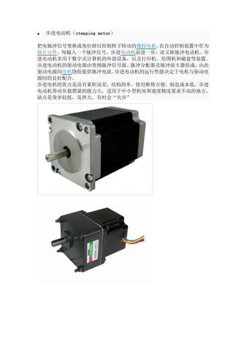
步进电动机(stepping motor)把电脉冲信号变换成角位移以控制转子转动的微特电机。
在自动控制装置中作为执行元件。
每输入一个脉冲信号,步进电动机前进一步,故又称脉冲电动机。
步进电动机多用于数字式计算机的外部设备,以及打印机、绘图机和磁盘等装置。
步进电动机的驱动电源由变频脉冲信号源、脉冲分配器及脉冲放大器组成,由此驱动电源向电机绕组提供脉冲电流。
步进电动机的运行性能决定于电机与驱动电源间的良好配合。
步进电机的优点是没有累积误差,结构简单,使用维修方便,制造成本低,步进电动机带动负载惯量的能力大,适用于中小型机床和速度精度要求不高的地方,缺点是效率较低,发热大,有时会“失步”罩极式电动机(Shaded Pole Motor)是单相交流电动机中最简单的一种,通常采用笼型斜槽铸铝转子。
它根据定子外形结构的不同,又分为凸极式罩极电动机和隐极式罩极电动机。
凸极式罩极凸极式罩极电动机的定子铁心外形为方形、矩形或圆形的磁场框架,磁极凸出,每个磁极上均有1个或多个起辅助作用的短路铜环,即罩极绕组。
凸极磁极上的集中绕组作为主绕组。
隐极式罩极隐极式罩极电动机的定子铁心与普通单相电动机的铁心相同,其定子绕组采用分布绕组,主绕组分布于定子槽内,罩极绕组不用短路铜环,而是用较粗的漆包线绕成分布绕组(串联后自行短路)嵌装在定子槽中(约为总槽数的1/3),起辅助组的作用。
主绕组与罩极绕组在空间相距一定的角度。
当罩极电动机的主绕组通电后,罩极绕组也会产生感应电流,使定子磁极被罩极绕组罩住部分的磁通与未罩部分向被罩部分的方向旋转。
罩极式电动机的优点就是结构简单,不用另加绕组和电容器,缺点是效率低,滑差大。
空调嵌入机使用的排水泵是典型的罩极电机,不良率低,一般故障为电机脏堵。
步进马达的详细讲解

步进电机的名称步进电机(stepping motor),步进电机(step motor),或者是脉冲电机(pulse motor),其它的如(stepper motor)等……有着各式各样的称呼方式,这些用日本话来表示的时候,就成为阶动电动机,还有,阶动就是一步一步阶段动作的意思,这各用另外一种语言来表示时,就是成为步进驱动的意思,总之,就是输入一个脉冲就会有一定的转角,分配转轴变位的电动机。
步进电机简介:步进电机是将电脉冲信号转变为角位移或线位移的开环控制组件。
在非超载的情况下,电机的转速、停止的位置只取决于脉冲信号的频率和脉冲数,而不受负载变化的影响,即给电机加一个脉冲信号,电机则转过一个步距角。
这一线性关系的存在,加上步进电机只有周期性的误差而无累积误差等特点。
使得在速度、位置等控制领域用步进电机来控制变的非常的简单。
单相步进电机有单路电脉冲驱动,输出功率一般很小,其用途为微小功率驱动。
多相步进电机有多相方波脉冲驱动,用途很广。
使用多相步进电机时,单路电脉冲信号可先通过脉冲分配器转换为多相脉冲信号,在经功率放大后分别送入步进电机各项绕组。
每输入一个脉冲到脉冲分配器,电机各相的通电状态就发生变化,转子会转过一定的角度(称为步距角)。
正常情况下,步进电机转过的总角度和输入的脉冲数成正比;连续输入一定频率的脉冲时,电机的转速与输入脉冲的频率保持严格的对应关系,不受电压波动和负载变化的影响。
在非超载的情况下,电机的转速、停止的位置只取决于脉冲信号的频率和脉冲数,而不受负载变化的影响,即给电机加一个脉冲信号,电机则转过一个步距角。
步进电机按旋转结构分两大类:1是圆型旋转电机如下图A 2直线型电机,结构就象一个圆型旋转电机被展开一样,如下图B一,步进电机的种类现在,在市场上所出现的步进电机有很多种类,依照性能及使用目的等有各自不同的区分使用。
举个例子,各自不同的区分使用有精密位置决定控制的混合型,或者是低价格想用简易控制系构成的PM型,由于电机的磁气构造分类,因此就性能上来说就会有影响,其它的有依步进电机的外观形状来分类,也有由驱动相数来分类,和驱动回路分类等。
步进马达 Stepping Motor 概要

2.PM型Stepping Motor
PM型Stepping Motor是指回转轴是用永久性磁石构成的马达。图2为最基本的一种PM型马达。下图里所标志的各磁场C端子并联后与电源+极相接,磁场驱动按Φ1,2,3,4的顺序移动,回转轴就按顺时针方向转动。根据此原理要想将Step的角度变小的话,只要增加固定子的齿轮数即可,但是此有一个限度。
図7.Bi-Polar驱动結線图
■Stepping Motor特性
关于Stepping Motor的一般性特性,做以下说明。
(a)Pull-inTorque
马达与收到的输入频率同步启动,并且这时产生最大扭矩。
(b)最大自启动频率
在无负荷状态下,与一定速度的信号同步启动同步停止的最高频率。
(c)Pull-out Torque
■Stepping Motor的种类
一般而言,Stepping Motor可以分为VR型(VariableReluctanceType),PM型(PermanentMagnetType),HB型(HybridType)等3种。
1.VR型Stepping Motor
VR型就是指齿轮状加工的回转轴(ROTOR)和磁场驱动的固定子(STATOR)之间形成的磁场里,回转轴的位置不同磁场电阻会不断地发生变化,使用在这里面的马达,有固定子的地方一被驱动,固定子的齿与最近的回转轴的齿轮相吸的这种类型,从Stepping Motor的扭矩发生原理分类时最基本的东西。
对于超出自启动领域,在速度或负荷扭矩不断上升时,马达能同步产生的最大扭矩。
(d)最大反应频率
在无负荷状态下,输入信号频率不断上升时,能同步反应的最大频率。
(e)Holding Torque
- 1、下载文档前请自行甄别文档内容的完整性,平台不提供额外的编辑、内容补充、找答案等附加服务。
- 2、"仅部分预览"的文档,不可在线预览部分如存在完整性等问题,可反馈申请退款(可完整预览的文档不适用该条件!)。
- 3、如文档侵犯您的权益,请联系客服反馈,我们会尽快为您处理(人工客服工作时间:9:00-18:30)。
步进电机简介s tepper motors2007-03-08 20:28步进电机在去有机床的生产车间都基本上有见过,但主要都是在数控机床,机床呢好象都用了私服电机步进电机我也有玩过一下是一个简易的数控平台设计我做了下位机和上位机的几乎所有程序下位机用了一天一夜用汇编写的 1千多行好恐怖因为赶着交很多其实还没写好插补还实现不了只是留了接口但终究没找到一个现成的又没时间要赶着做上位机的程序!!!!!也搞了一天也来不及做好就验收了~~~~更巧的是验收时步进电机出了问题没被细问~~险啊!!!!三天把人家三个星期的工作都做了已经很不容易了啊在这三天只吃了一顿米饭其他时间 --北方大饼!!来自/Control-Technology/Motor-Control-Circuits/steppe r-motors.htm一、前言步进电机是将电脉冲信号转变为角位移或线位移的开环控制元件。
在非超载的情况下,电机的转速、停止的位置只取决于脉冲信号的频率和脉冲数,而不受负载变化的影响,即给电机加一个脉冲信号,电机则转过一个步距角。
这一线性关系的存在,加上步进电机只有周期性的误差而无累积误差等特点。
使得在速度、位置等控制领域用步进电机来控制变的非常的简单。
虽然步进电机已被广泛地应用,但步进电机并不能象普通的直流电机,交流电机在常规下使用。
它必须由双环形脉冲信号、功率驱动电路等组成控制系统方可使用。
因此用好步进电机却非易事,它涉及到机械、电机、电子及计算机等许多专业知识。
目前,生产步进电机的厂家的确不少,但具有专业技术人员,能够自行开发,研制的厂家却非常少,大部分的厂家只一、二十人,连最基本的设备都没有。
仅仅处于一种盲目的仿制阶段。
这就给用户在产品选型、使用中造成许多麻烦。
签于上述情况,我们决定以广泛的感应子式步进电机为例。
叙述其基本工作原理。
望能对广大用户在选型、使用、及整机改进时有所帮助。
二、感应子式步进电机工作原理(一)反应式步进电机原理由于反应式步进电机工作原理比较简单。
下面先叙述三相反应式步进电机原理。
电机转子均匀分布着很多小齿,定子齿有三个励磁绕阻,其几何轴线依次分别与转子齿轴线错开。
0、1/3て、2/3て,(相邻两转子齿轴线间的距离为齿距以て表示),即A与齿1相对齐,B与齿2向右错开1/3て,C与齿3向右错开2/3て,A'与齿5相对齐,(A'就是A,齿5就是齿1)下面是定转子的展开图:2、旋转:如A相通电,B,C相不通电时,由于磁场作用,齿1与A对齐,(转子不受任何力以下均同)。
如B相通电,A,C相不通电时,齿2应与B对齐,此时转子向右移过1/3て,此时齿3与C偏移为1/3て,齿4与A偏移(て-1/3て)=2/3て。
如C相通电,A,B相不通电,齿3应与C对齐,此时转子又向右移过1/3て,此时齿4与A偏移为1/3て对齐。
如A相通电,B,C相不通电,齿4与A对齐,转子又向右移过1/3て这样经过A、B、C、A分别通电状态,齿4(即齿1前一齿)移到A相,电机转子向右转过一个齿距,如果不断地按A,B,C,A……通电,电机就每步(每脉冲)1/3て,向右旋转。
如按A,C,B,A……通电,电机就反转。
由此可见:电机的位置和速度由导电次数(脉冲数)和频率成一一对应关系。
而方向由导电顺序决定。
不过,出于对力矩、平稳、噪音及减少角度等方面考虑。
往往采用A-AB-B-BC-C-CA-A这种导电状态,这样将原来每步1/3て改变为1/6て。
甚至于通过二相电流不同的组合,使其1/3て变为1/12て,1/24て,这就是电机细分驱动的基本理论依据。
不难推出:电机定子上有m相励磁绕阻,其轴线分别与转子齿轴线偏移1/m,2/m……(m-1)/m,1。
并且导电按一定的相序电机就能正反转被控制——这是步进电机旋转的物理条件。
只要符合这一条件我们理论上可以制造任何相的步进电机,出于成本等多方面考虑,市场上一般以二、三、四、五相为多。
电机一旦通电,在定转子间将产生磁场(磁通量Ф)当转子与定子错开一定角度产生力F与(dФ/dθ)成正比其磁通量Ф=Br*SBr为磁密,S为导磁面积F与L*D*Br成正比L为铁芯有效长度,D为转子直径Br=N·I/RN·I为励磁绕阻安匝数(电流乘匝数)R为磁阻。
力矩=力*半径力矩与电机有效体积*安匝数*磁密成正比(只考虑线性状态)因此,电机有效体积越大,励磁安匝数越大,定转子间气隙越小,电机力矩越大,反之亦然。
二)感应子式步进电机感应子式步进电机与传统的反应式步进电机相比,结构上转子加有永磁体,以提供软磁材料的工作点,而定子激磁只需提供变化的磁场而不必提供磁材料工作点的耗能,因此该电机效率高,电流小,发热低。
因永磁体的存在,该电机具有较强的反电势,其自身阻尼作用比较好,使其在运转过程中比较平稳、噪音低、低频振动小。
感应子式步进电机某种程度上可以看作是低速同步电机。
一个四相电机可以作四相运行,也可以作二相运行。
(必须采用双极电压驱动),而反应式电机则不能如此。
例如:四相,八相运行(A-AB-B-BC-C-CD-D-DA-A)完全可以采用二相八拍运行方式.不难发现其条件为C=,D=.一个二相电机的内部绕组与四相电机完全一致,小功率电机一般直接接为二相,而功率大一点的电机,为了方便使用,灵活改变电机的动态特点,往往将其外部接线为八根引线(四相),这样使用时,既可以作四相电机使用,可以作二相电机绕组串联或并联使用。
2、分类感应子式步进电机以相数可分为:二相电机、三相电机、四相电机、五相电机等。
以机座号(电机外径)可分为:42BYG(BYG为感应子式步进电机代号)、57BYG、86BYG、110BYG、(国际标准),而像70BYG、90BYG、130BYG等均为国内标准。
3、步进电机的静态指标术语相数:产生不同对极N、S磁场的激磁线圈对数。
常用m表示。
拍数:完成一个磁场周期性变化所需脉冲数或导电状态用n表示,或指电机转过一个齿距角所需脉冲数,以四相电机为例,有四相四拍运行方式即AB-BC-CD-DA-AB,四相八拍运行方式即 A-AB-B-BC-C-CD-D-DA-A.步距角:对应一个脉冲信号,电机转子转过的角位移用θ表示。
θ=360度(转子齿数J*运行拍数),以常规二、四相,转子齿为50齿电机为例。
四拍运行时步距角为θ=360度/(50*4)=1.8度(俗称整步),八拍运行时步距角为θ=360度/(50*8)=0.9度(俗称半步)。
定位转矩:电机在不通电状态下,电机转子自身的锁定力矩(由磁场齿形的谐波以及机械误差造成的)静转矩:电机在额定静态电作用下,电机不作旋转运动时,电机转轴的锁定力矩。
此力矩是衡量电机体积(几何尺寸)的标准,与驱动电压及驱动电源等无关。
虽然静转矩与电磁激磁安匝数成正比,与定齿转子间的气隙有关,但过份采用减小气隙,增加激磁安匝来提高静力矩是不可取的,这样会造成电机的发热及机械噪音。
4、步进电机动态指标及术语:1、步距角精度:步进电机每转过一个步距角的实际值与理论值的误差。
用百分比表示:误差/步距角*100%。
不同运行拍数其值不同,四拍运行时应在5%之内,八拍运行时应在15%以内。
2、失步:电机运转时运转的步数,不等于理论上的步数。
称之为失步。
3、失调角:转子齿轴线偏移定子齿轴线的角度,电机运转必存在失调角,由失调角产生的误差,采用细分驱动是不能解决的。
4、最大空载起动频率:电机在某种驱动形式、电压及额定电流下,在不加负载的情况下,能够直接起动的最大频率。
5、最大空载的运行频率:电机在某种驱动形式,电压及额定电流下,电机不带负载的最高转速频率。
6、运行矩频特性:电机在某种测试条件下测得运行中输出力矩与频率关系的曲线称为运行矩频特性,这是电机诸多动态曲线中最重要的,也是电机选择的根本依据。
如下图所示:其它特性还有惯频特性、起动频率特性等。
电机一旦选定,电机的静力矩确定,而动态力矩却不然,电机的动态力矩取决于电机运行时的平均电流(而非静态电流),平均电流越大,电机输出力矩越大,即电机的频率特性越硬。
如下图所示:其中,曲线3电流最大、或电压最高;曲线1电流最小、或电压最低,曲线与负载的交点为负载的最大速度点。
要使平均电流大,尽可能提高驱动电压,使采用小电感大电流的电机。
7、电机的共振点:步进电机均有固定的共振区域,二、四相感应子式步进电机的共振区一般在180-250pps之间(步距角1.8度)或在400pps左右(步距角为0.9 度),电机驱动电压越高,电机电流越大,负载越轻,电机体积越小,则共振区向上偏移,反之亦然,为使电机输出电矩大,不失步和整个系统的噪音降低,一般工作点均应偏移共振区较多。
8、电机正反转控制:当电机绕组通电时序为AB-BC-CD-DA或()时为正转,通电时序为DA-CA-BC-AB或()时为反转。
三、驱动控制系统组成使用、控制步进电机必须由环形脉冲,功率放大等组成的控制系统,其方框图如下:1、脉冲信号的产生。
脉冲信号一般由单片机或CPU产生,一般脉冲信号的占空比为0.3-0.4左右,电机转速越高,占空比则越大。
2、信号分配我厂生产的感应子式步进电机以二、四相电机为主,二相电机工作方式有二相四拍和二相八拍二种,具体分配如下:二相四拍为,步距角为1.8度;二相八拍为,步距角为0.9度。
四相电机工作方式也有二种,四相四拍为AB-BC-CD-DA-AB,步距角为1.8度;四相八拍为AB-B-BC-C-CD-D-AB,(步距角为0.9度)。
3、功率放大功率放大是驱动系统最为重要的部分。
步进电机在一定转速下的转矩取决于它的动态平均电流而非静态电流(而样本上的电流均为静态电流)。
平均电流越大电机力矩越大,要达到平均电流大这就需要驱动系统尽量克服电机的反电势。
因而不同的场合采取不同的的驱动方式,到目前为止,驱动方式一般有以下几种:恒压、恒压串电阻、高低压驱动、恒流、细分数等。
为尽量提高电机的动态性能,将信号分配、功率放大组成步进电机的驱动电源。
我厂生产的SH系列二相恒流斩波驱动电源与单片机及电机接线图如下:说明:CP 接CPU脉冲信号(负信号,低电平有效)OPTO 接CPU+5VFREE 脱机,与CPU地线相接,驱动电源不工作DIR 方向控制,与CPU地线相接,电机反转VCC 直流电源正端GND 直流电源负端A 接电机引出线红线接电机引出线绿线B 接电机引出线黄线接电机引出线蓝线步进电机一经定型,其性能取决于电机的驱动电源。
步进电机转速越高,力距越大则要求电机的电流越大,驱动电源的电压越高。
电压对力矩影响如下:4、细分驱动器在步进电机步距角不能满足使用的条件下,可采用细分驱动器来驱动步进电机,细分驱动器的原理是通过改变相邻(A,B)电流的大小,以改变合成磁场的夹角来控制步进电机运转的。
