思科设备三层交换机的vlan间通信配置
实验9 通过三层交换机实现VLAN间通信的配置
实验9通过三层交换机实现VLAN间通信的配置
实验目的:熟练掌握三层交换机VLAN的配置
实验设备:2台Catalyst2950交换机,1台三层交换机Catalyst3560,交叉线2条,4台WindowsPC机,超级终端,反转线及相应接口转换器。
实验要求:
通过配置三层交换机使不同VLAN的电脑能够互相通信
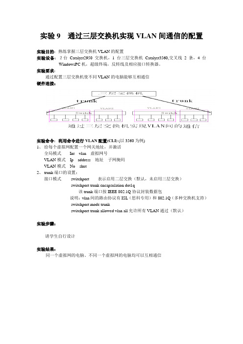
硬件连接:
实验命令:利用命令进行VLAN配置(CLI) (以3560为例)
1、给每个虚拟网配置一个网关地址,并激活
全局模式Int vlan 虚拟网号
VLAN模式Ip address 地址子网掩码
VLAN模式No shut
2、trunk端口的设置:
接口模式switchport 表示启用二层交换(默认,未启用三层交换)
switchport trunk encapsulation dot1q
该trunk端口按IEEE 802.1Q协议封装数据包
说明:vlan间的路由协议有ISL(思科专用)和802.1Q(多种交换机支持)
switchport mode trunk
switchport trunk allowed vlan all允许所有VLAN通过(默认)
实验步骤:
请学生自行设计
实验结果:
同一个虚拟网的电脑、不同一个虚拟网的电脑均可以互相通信。
CISCO三层交换机VLAN配置说明
CISCO三层交换机VLAN配置说明CISCO三层交换机VLAN配置说明。
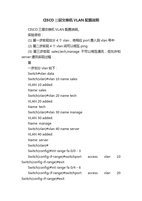
实验目标:(1) 第一步实现划分4个vlan,将相应port置入到vlan号中(2) 第二步实现4个vlan间可以相互ping(3) 第三步实现sales,tech,manage不可以相互通讯,但允许和server通讯实现过程:第一步划分vlan如下:Switch#vlan dataSwitch(vlan)#vlan 10 name salesVLAN 10 added:Name: salesSwitch(vlan)#vlan 20 name techVLAN 20 added:Name: techSwitch(vlan)#vlan 30 name manageVLAN 30 added:Name: manageSwitch(vlan)#vlan 40 name serverVLAN 40 added:Name: serverSwitch(vlan)#Switch(config)#int range fa 0/0 - 3Switch(config-if-range)#switchport access vlan 10 Switch(config-if-range)#exitSwitch(config)#int range fa 0/4 - 6Switch(config-if-range)#switchport access vlan 20 Switch(config-if-range)#exitSwitch(config)#int range fa 0/7 - 8Switch(config-if-range)#switchport access vlan 30 Switch(config-if-range)#exitSwitch(config)#int fa 0/9Switch(config-if)#switSwitch(config-if)#switchport acceSwitch(config-if)#switchport access vlan 40 Switch(config-if)#exit查看Switch#sh vlan-switchVLAN Name Status Ports---- -------------------------------- --------- -------------------------------1 default active Fa0/10, Fa0/11, Fa0/12, Fa0/13 Fa0/14, Fa0/1510 sales active Fa0/1, Fa0/2, Fa0/320 tech active Fa0/4, Fa0/5, Fa0/630 manage active Fa0/7, Fa0/840 server active Fa0/91002 fddi-default active第二步实现4个vlan内的服务器互相pingSwitch(config)#int fa 0/0Switch(config-if)#switchport mode trunkRouter(config-if)#exitRouter(config)#int fa 0/0Router(config-if)#no shutRouter(config-if)#no ip addressRouter(config-if)#exitRouter(config)#int fa0/0.1Router(config-subif)#encapsulation dot1Q 10Router(config-subif)#ip addreRouter(config-subif)#ip address 192.168.33.1 255.255.255.0 Router(config-subif)#exitRouter(config)#int fa0/0.2Router(config-subif)#encapsulation dot1Q 20 Router(config-subif)#ip address 192.168.34.1 255.255.255.0 Router(config-subif)#exitRouter(config)#int fa0/0.3Router(config-subif)#encapsulation dot1Q 30 Router(config-subif)#ip address 192.168.35.1 255.255.255.0 Router(config-subif)#exitRouter(config)#int fa0/0.4Router(config-subif)#encapsulation dot1Q 40 Router(config-subif)#ip address 192.168.36.1 255.255.255.0 Router(config-subif)#查看路由器:interface FastEthernet0/0no ip addressduplex autospeed auto!interface FastEthernet0/0.1 encapsulation dot1Q 10ip address 192.168.33.1 255.255.255.0 !interface FastEthernet0/0.2 encapsulation dot1Q 20ip address 192.168.34.1 255.255.255.0 !interface FastEthernet0/0.3 encapsulation dot1Q 30ip address 192.168.35.1 255.255.255.0!interface FastEthernet0/0.4encapsulation dot1Q 40ip address 192.168.36.1 255.255.255.0!测试:VPCS 1 >shNAME IP/CIDR GATEWAY LPORT RPORT PC1 192.168.33.2/24 192.168.33.1 10001 21001PC2 0.0.0.0/0 0.0.0.0 10002 21002PC3 0.0.0.0/0 0.0.0.0 10003 21003PC4 192.168.34.2/24 192.168.34.1 10004 21004PC5 0.0.0.0/0 0.0.0.0 10005 21005PC6 0.0.0.0/0 0.0.0.0 10006 21006PC7 192.168.35.2/24 192.168.35.1 10007 21007PC8 0.0.0.0/0 0.0.0.0 10008 21008PC9 192.168.36.2/24 192.168.36.1 10009 21009 VPCS 1 >ping 192.168.34.2192.168.34.2 icmp_seq=1 timeout192.168.34.2 icmp_seq=2 time=45.000 ms192.168.34.2 icmp_seq=3 time=47.000 ms192.168.34.2 icmp_seq=4 time=43.000 ms192.168.34.2 icmp_seq=5 time=8.000 msVPCS 1 >ping 192.168.35.2192.168.35.2 icmp_seq=1 time=43.000 ms192.168.35.2 icmp_seq=2 time=14.000 ms192.168.35.2 icmp_seq=3 time=8.000 ms192.168.35.2 icmp_seq=4 time=10.000 ms192.168.35.2 icmp_seq=5 time=12.000 msVPCS 1 >ping 192.168.36.2192.168.36.2 icmp_seq=1 timeout192.168.36.2 icmp_seq=2 time=47.000 ms192.168.36.2 icmp_seq=3 time=6.000 ms192.168.36.2 icmp_seq=4 time=10.000 ms192.168.36.2 icmp_seq=5 time=43.000 msOK,这一步也成功了。
三层交换机划分3个vlan ,实现其互相通迅.

综合实验一台思科三层交换机划分3个vlan vlan 2:ip 192.168.1.1 255.255.255.0 192.168.1.254 网段vlan 3 :ip 192.168.2.1 255.255.255.0 192.168.2.254 vlan 4 ip 192.168.3.1 255.255.255.0192.168.3.254 各vlan 之间能互相通迅. 现在增加1台cisco路由想实现共享我们的PC0、PC1处在VLAN2中,PC2、PC3处在VLAN3中,Server0处在VLAN4中。
现在要使我们内网能够正常访问我们的Server0服务器,然后同时还要能够访问我们的ISP 外网的WWW服务器。
三层交换机的配置Switch#config tSwitch(config)#vlan 2 创建VLAN2Switch(config-vlan)#exiSwitch(config)#vlan 3 创建VLAN3Switch(config-vlan)#exiSwitch(config)#vlan 4 创建VLAN4Switch(config-vlan)#exitSwitch(config)#int fa0/2 将我们的fa0/2添加到VLAN2中Switch(config-if)#sw mo acSwitch(config-if)#sw ac vlan 2Switch(config-if)#exitSwitch(config)#int fa0/3将我们的FA0/3添加到VLAN3中Switch(config-if)#sw mo acSwitch(config-if)#sw ac vlan 3Switch(config-if)#exitSwitch(config)#int fa0/4 将我们的FA0/4添加到VLAN4中Switch(config-if)#sw mo acSwitch(config-if)#sw ac vlan 4Switch(config-if)#exitSwitch(config)#int vlan 2 给我们的VLAN2添加一个IP地址,用于不同网段之间互相访问Switch(config-if)#ip add 192.168.1.1 255.255.255.0Switch(config-if)#exitSwitch(config)#int vlan 3 给我们的VLAN3添加一个IP地址Switch(config-if)#ip add 192.168.2.1 255.255.255.0Switch(config-if)#exitSwitch(config)#int vlan 4给我们的VLAN4添加一个IP地址Switch(config-if)#ip add 192.168.3.1 255.255.255.0Switch(config-if)#no shutSwitch(config-if)#exit以下几行是用来给我们不同的VLAN内的主机自动分配我们的IP地址。
思科Cisco交换机配置——三层交换机实现VLAN间通信实验详解

思科Cisco交换机配置——三层交换机实现VLAN间通信实验详解本⽂实例讲述了思科Cisco三层交换机实现VLAN间通信实验。
分享给⼤家供⼤家参考,具体如下:⼀、实验⽬的:⽤三层交换机让同⼀vlan的主机能通信,不同vlan的主机也能通信⼆、拓扑图如下三、具体步骤如下:先给每台主机和服务器配置ip地址和⽹关例:(1)S1三层交换机配置:Switch>en --进⼊特权模式Switch#conf t --进⼊全局配置模式Enter configuration commands, one per line. End with CNTL/Z.Switch(config)#hostname S1 --修改三层交换机主机名为S1S1(config)#vtp domain test --创建vtp域Domain name already set to test.S1(config)#vtp mode server --设置当前交换机在vtp的⼯作模式为server Device mode already VTP SERVER.S1(config)#vlan 10 --创建vlan 10S1(config-vlan)#vlan 20 --创建vlan 20S1(config-vlan)#vlan 30 --创建vlan 30S1(config-vlan)#vlan 40 --创建vlan40S1(config-vlan)#interface f0/1 --进⼊端⼝S1(config-if)#switchport mode access --将端⼝模式改为access模式S1(config-if)#switchport mode trunk --将端⼝模式改为trunk模式S1(config-if)#interface range f0/2-3 --进⼊端⼝S1(config-if-range)#switchport mode access --将端⼝模式改为access模式S1(config-if-range)#switchport access vlan 40 --将端⼝划⼊vlan 40S1(config-if-range)#exit --返回上⼀级S1(config)#ip routing --启动三层交换机的路由功能S1(config)#interface vlan 10 --进⼊vlan 10S1(config-if)#ip address 192.168.1.254 255.255.255.0 --给vlan 10添加ip地址S1(config-if)#interface vlan 20 --进⼊vlan 20S1(config-if)#ip address 192.168.2.254 255.255.255.0 --给vlan 20添加ip地址S1(config-if)#interface vlan 30 --进⼊vlan 30S1(config-if)#ip address 192.168.3.254 255.255.255.0 --给vlan 30添加ip地址S1(config-if)#interface vlan 40 --进⼊vlan 40S1(config-if)#ip address 192.168.4.254 255.255.255.0 --给vlan 40添加ip地址S1(config-if)#end --返回特权模式S1#copy running-config startup-config --保存配置[OK] --保存成功(2)S2交换机配置Switch>en --进⼊特权模式Switch#conf t --进⼊全局配置模式Enter configuration commands, one per line. End with CNTL/Z.Switch(config)#hostname S2 --修改交换机名为S2S2(config)#vtp mode client --设置当前交换机在vtp中为客户机模式Device mode already VTP CLIENT.S2(config)#interface f0/10 --进⼊端⼝S2(config-if)#switchport mode trunk --将端⼝设置为trunk模式S2(config-if)#interface f0/1 --进⼊端⼝S2(config-if)#switchport mode access --将端⼝设置为access模式S2(config-if)#switchport access vlan 30 --将端⼝划⼊vlan30S2(config-if)#interface f0/2 --进⼊端⼝S2(config-if)#switchport mode access --将端⼝设置为access模式S2(config-if)#switchport access vlan 20 --将端⼝划⼊vlan 20S2(config-if)#interface f0/3 --进⼊端⼝S2(config-if)#switchport mode access --将端⼝设置为access模式S2(config-if)#switchport access vlan 10 --将端⼝划⼊vlan 10S2(config-if)#end --返回特权模式S2#copy running-config startup-config --保存配置[OK] --保存成功(3)S3交换机配置Switch>en --进⼊特权模式Switch#conf t --进⼊全局配置模式Enter configuration commands, one per line. End with CNTL/Z.Switch(config)#hostname S3 --修改交换机名为S3S3(config)#vtp mode client --设置当前交换机在vtp中为客户模式Device mode already VTP CLIENT.S3(config)#interface range f0/10-12 --进⼊端⼝S3(config-if-range)#switchport mode trunk --将端⼝设置为trunk模式S3(config-if-range)#interface f0/1 --进⼊端⼝S3(config-if)#switchport mode access --将端⼝设置为access模式S3(config-if)#switchport access vlan 30 --将端⼝划⼊vlan 30S3(config-if)#interface f0/2 --进⼊端⼝S3(config-if)#switchport mode access --将端⼝设置为access模式S3(config-if)#switchport access vlan 20 --将端⼝划⼊vlan20S3(config-if)#interface f0/3 --进⼊端⼝S3(config-if)#switchport mode access --将端⼝设置为access模式S3(config-if)#switchport access vlan 10 --将端⼝划⼊vlan 20S3(config-if)#end --返回特权模式S3#copy running-config startup-config --保存配置[OK] --保存成功(4)S4交换机配置Switch>en --进⼊特权模式Switch#conf t --进⼊全局配置模式Enter configuration commands, one per line. End with CNTL/Z.Switch(config)#hostname S4 --修改交换机名为S4S4(config)#vtp mode client --设置当前交换机在vtp中为客户模式Device mode already VTP CLIENT.S4(config)#interface f0/10 --进⼊端⼝S4(config-if)#switchport mode trunk --将端⼝设置为trunk模式S4(config-if)#interface f0/1 --进⼊端⼝S4(config-if)#switchport mode access --将端⼝设置为access模式S4(config-if)#switchport access vlan 30 --将端⼝划⼊vlan 30S4(config-if)#interface f0/2 --进⼊端⼝S4(config-if)#switchport mode access --将端⼝设置为access模式S4(config-if)#switchport access vlan 20 --将端⼝划⼊vlan 20S4(config-if)#interface f0/3 --进⼊端⼝S4(config-if)#switchport mode access --将端⼝设置为access模式S4(config-if)#switchport access vlan 10 --将端⼝划⼊vlan 10S4(config-if)#end --返回特权模式S4#copy running-config startup-config --保存配置[OK] --保存成功四、验证测试不同vlan下的主机是否互通(1)PC11与PC33vlan10与vlan30互通(2)PC13与PC21vlan10与vlan20互通。
计算机网络实验二(三层交换机VLAN的配置及VLAN间的通信)

实验二Catalyst 3550 三层交换机VLAN的配置及VLAN间的通信(验证性)一、实验目的:(2学时)掌握如何使用三层交换机配置VLAN。
利用三层交换实现VLAN间的路由。
熟悉VLAN的原理。
二、实验环境和要求:选择桌面上的“Boson NetSim for CCNP”图标进入实验环境,选择“Boson Network Designer”图标进入拓扑结构设计环境。
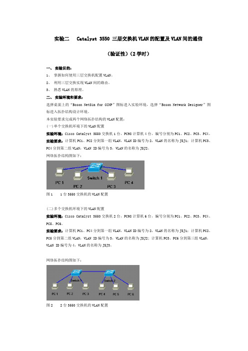
本实验要求完成两个网络拓扑结构的VLAN配置:(一)单个交换机环境下的VLAN配置实验环境:Cisco Catalyst 3550交换机1台,PC98计算机4台,编号分别为PC1、PC2、PC3、PC4。
实验要求:计算机PC1、PC2分到第一组VLAN,VLAN ID编号为2,VLAN的名称为JSJ1;计算机PC3、PC4分到第二组VLAN,VLAN ID编号为3,VLAN的名称为JSJ2。
网络拓扑结构图如下:图1 1台3550交换机的VLAN配置(二)多个交换机环境下的VLAN配置实验环境:Cisco Catalyst 3550交换机2台,PC98计算机4台,编号分别为PC1、PC2、PC3、PC4。
实验要求:计算机PC1、PC4分到第一组VLAN,VLAN ID编号为2,VLAN的名称为JSJ1;计算机PC2、PC5分到第二组VLAN,VLAN ID编号为3,VLAN的名称为JSJ2; 计算机PC3、PC6分到第三组VLAN,VLAN ID编号为4,VLAN的名称为JSJ3。
网络拓扑结构图如下:图2 2台3550交换机的VLAN配置三、实验内容和步骤:(一)单个交换机环境下的VLAN配置第一步:进入实验环境,按照实验要求,在Boson Network Designer中完成网络拓扑结构的设计。
注意:3550交换机Switch1的Fast Ethernet 0/1端口和PC1的Ethernet 0端口连接,Fast Ethernet 0/2端口和PC2的Ethernet 0端口连接,Fast Ethernet 0/3端口和PC3的Ethernet 0端口连接,Fast Ethernet 0/4端口和PC4的Ethernet 0端口连接。
cisco_交换机vlan间通信

VLAN跨交换机通信注:图中SwitchA 为3550、SwitchB为1908交换机。
步骤1:在SwitchA上创建VLAN10,将它命名为teacher。
SwitchA # configure terminalSwitchA(config)# vlan 10SwitchA(config-vlan)# name teacherSwitchA(config-vlan)#exitSwitchA(config)# interface fa 0/5SwitchA(config-if)# switchport access vlan 10SwitchA(config-if)#end验证测试:已创建了VLAN10,端口已分配好。
SwitchA# show vlan id 10VLAN Name Status Ports---- ------------------ --------- ---------------10 teacher active Fa0/5步骤2:在SwitchA上创建VLAN20,将它命名为student。
SwitchA# configure terminalSwitchA(config)# vlan 20SwitchA(config-vlan)# name studentSwitchA(config-vlan)#exitSwitchA(config)# interface fa 0/7SwitchA(config-if)# switchport access vlan 20SwitchA(config-if)# end验证测试:已创建了VLAN20,端口已分配好。
SwitchA# show vlan id 20VLAN Name Status Ports---- ------------------ --------- ---------------20 student active Fa0/7步骤3:在SwitchA上,将与SwitchB相连的端口(设为0/8)定义为Tag VLAN 模式。
VLAN间路由的配置-三层交换的配置示例-思科

三层交换的配置举例-S2上配置VLAN虚接口
要求配置三层交换,使 PC1和PC2所在的两个VLAN能够互相通信。
S1 F0/24
Trunk
S2 F0/24
F0/1 VLAN 10
F0/2 VLAN 20
VLANIF 10 10.1.1.254/24 VLANIF 20 20.1.1.254/24
PC1 10.1.1.1/24
PC2 20.1.1.1/24
三层交换的配置举例-S1上配置VLAN
要求配置三层交换,使 PC1和PC2所在的两个VLAN能够互相通信。
S1 F0/24
Trunk
S2 F0/24
F0/1 VLAN 10
F0/2 VLAN 20
VLANIF 10 10.1.1.254/24 VLANIF 20 20.1.1.254/24
三层交换的配置举例-S1上的配置Trunk
要求配置三层交换,使 PC1和PC2所在的两个VLAN能够互相通信。
S1 F0/24
Trunk
S2 F0/24
F0/1 VLAN 10
F0/2 VLAN 20
VLANIF 10 10.1.1.254/24 VLANIF 20 20.1.1.254/24
PC1 10.1.1.1/24
S1 F0/24
Trunk
S2 F0/24
F0/1 VLAN 10F0/2Fra bibliotekVLAN 20
VLANIF 10 10.1.1.254/24 VLANIF 20 20.1.1.254/24
PC1 10.1.1.1/24
PC2 20.1.1.1/24
S1(config)#interface f0/1 S1(config-if)#switchport mode access S1(config-if)#switchport access vlan 10 S1(config-if)#interface f0/2 S1(config-if)#switchport mode access S1(config-if)#switchport access vlan 20
在一台三层交换上,不同VLAN相互通信配置方法

在⼀台三层交换上,不同VLAN相互通信配置⽅法本实验需求:通过在cisco catalyst 3550来规划VLAN 100 和VLAN 200,并且配置DHCP 让VLAN100⼈事部计算机获得IP地址为192.168.0.0/24,让VLAN200市场部计算机获得IP地址为172.16.0.0/24。
因为市场部和⼈事部因为业务上的关系,需要两台服务器相互通信,所在还需要在3550上配置VLAN间相互通信。
实验拓扑:实验过程第⼀步配置Catalyst 3550基础配置复制代码代码如下:Switch>Switch>enableSwitch#conf tEnter configuration commands, one per line. End with CNTL/Z.Switch(config)#host 35503550(config)#no ip do lo3550(config)#line con 03550(config-line)#no exec-t3550(config-line)#logg syn3550(config-line)#exit第⼆步在Catalyst 3550 划分VLAN 100和VLAN 200 //进⼊全局配置模式下,划分VLAN(请问catalyst 3500⽀持在全局模式下划分VLAN吗?)复制代码代码如下:3550(config)#vlan 100//给VLAN100命名3550(config-vlan)#name renshibo3550(config-vlan)#int f0/133550(config-if)#switchport mode access3550(config-if)#switchport access vlan 1003550(config-if)#spanning-tree portfast//请问什么时候需要在交换机接⼝下配置portfast?这⾥如果不配置可以吗?%Warning: portfast should only be enabled on ports connected to a singlehost. Connecting hubs, concentrators, switches, bridges, etc... to thisinterface when portfast is enabled, can cause temporary bridging loops.Use with CAUTION%Portfast has been configured on FastEthernet0/13 but will onlyhave effect when the interface is in a non-trunking mode.3550(config-if)#vlan 2003550(config-vlan)#name shichangbo3550(config-vlan)#int f0/153550(config-if)#sw mo acc3550(config-if)#sw acc vlan 2003550(config-if)#spanning-tree portfast%Warning: portfast should only be enabled on ports connected to a singlehost. Connecting hubs, concentrators, switches, bridges, etc... to thisinterface when portfast is enabled, can cause temporary bridging loops.Use with CAUTION%Portfast has been configured on FastEthernet0/15 but will onlyhave effect when the interface is in a non-trunking mode.//验证VLAN的配置3550#show vlan briefVLAN Name Status Ports---- -------------------------------- --------- -------------------------------1 default active Fa0/1, Fa0/2, Fa0/3, Fa0/4Fa0/5, Fa0/6, Fa0/7, Fa0/8Fa0/9, Fa0/10, Fa0/11, Fa0/12Fa0/14, Fa0/16, Fa0/17, Fa0/18Fa0/23, Gi0/1, Gi0/2100 renshibo active Fa0/13200 shichangbo active Fa0/151002 fddi-default act/unsup1003 token-ring-default act/unsup1004 fddinet-default act/unsup1005 trnet-default act/unsup第三步配置SVI(交换虚拟接⼝)复制代码代码如下:3550#conf tEnter configuration commands, one per line. End with CNTL/Z.//进⼊VLAN 100 虚拟接⼝下3550(config)#int vlan 100//增加接⼝描述,以便将来排错更加⽅便3550(config-if)#description Connection to renshibo//这⾥配置的IP地址就是⼈事部PC的默认⽹关地址,如果VLAN接⼝不配置IP地址,后⾯的DHCP配置中,PC能否获得IP地址吗??3550(config-if)#ip add 192.168.0.1 255.255.255.03550(config-if)#no sh3550(config-if)#int vlan 20000:13:22: %LINEPROTO-5-UPDOWN: Line protocol on Interface Vlan200, changed state to up3550(config-if)#description Connection to shichangbo3550(config-if)#ip add 172.16.0.1 255.255.255.03550(config-if)#no sh3550(config-if)#3550#conf t//开启catalyst 3550三层交换路由功能(默认是关闭的)请问cisco catalyst那些型号交换机是三层交换机?3550(config)#ip routing3550(config)#exit3550#sh ip route//两条直连路由条⽬Codes: C - connected, S - static, R - RIP, M - mobile, B - BGPD - EIGRP, EX - EIGRP external, O - OSPF, IA - OSPF inter areaN1 - OSPF NSSA external type 1, N2 - OSPF NSSA external type 2E1 - OSPF external type 1, E2 - OSPF external type 2, E - EGPi - IS-IS, su - IS-IS summary, L1 - IS-IS level-1, L2 - IS-IS level-2ia - IS-IS inter area, * - candidate default, U - per-user static routeo - ODR, P - periodic downloaded static routeGateway of last resort is not set172.16.0.0/24 is subnetted, 1 subnetsC 172.16.0.0 is directly connected, Vlan200C 192.168.0.0/24 is directly connected, Vlan100Designated bridge has priority 32768, address ccd1.0a80.0000Designated port id is 129.65, designated path cost 0Timers: message age 0, forward delay 0, hold 0Number of transitions to forwarding state: 1BPDU: sent 993, received 92第四步在Catalyst 3550上配置DHCP,以便于VLAN100和VLAN200下客户端获得IP地址,掩码,⽹关,DNS等复制代码代码如下://全局下打开DHCP服务.默认是开启的吗?那为什么还要需要开启了?3550(config)#service dhcp//关闭dhcp 客户端IP冲突⽇志记录信息3550(config)#no ip dhcp conflict logging//配置地址池名称,地址池名称为任意字符(这⾥定义的名字VLAN的名称)3550(config)#ip dhcp pool renshibo//配置PC所获得⽹段地址范围,和掩码,(这⾥有⼏种命令语句格式)(network 192.168.0.0 255.255.255.0)3550(dhcp-config)#network 192.168.0.0 /24//配置⽹关地址3550(dhcp-config)#default-router 192.168.0.1//配置DNS(域名解析服务器)可选配置请问什么时候PC需要配置DNS地址?局域⽹通讯需要吗?3550(dhcp-config)#dns 218.30.19.40 61.134.1.4//配置域名3550(dhcp-config)#domain-name //配置地址租期为永久3550(dhcp-config)#lease infinite3550(dhcp-config)#exit//配置排除的IP地址范围,不从地址池内分配的地址,不配置排除地址可以吗?3550(config)#ip dhcp excluded-address 192.168.0.13550(config)#ip dhcp pool shichangbo3550(dhcp-config)#network 172.16.0.0 /243550(dhcp-config)#default-router 172.16.0.13550(dhcp-config)#dns 218.30.19.40 61.134.1.43550(dhcp-config)#domain-name 3550(dhcp-config)#lease infinite3550(dhcp-config)#exit3550(config)#ip dhcp excluded-address 172.16.0.1第五步在市场部PC上验证是否能从catalyst 3550获得IP地址, 如图:开始-运⾏-cmd-ipconfig /all第六步在Catalyst 3550查看PC获得的IP地址是否正确复制代码代码如下://查看DHCP绑定信息3550#sh ip dhcp bindingIP address Client-ID/ (MAC地址) Lease expiration TypeHardware address172.16.0.2 0100.16d3.249f.fd Infinite Automatic192.168.0.2 0100.1641.15e8.5c Infinite Automatic第七步在交换机测试是否可以ping通市场部和⼈事部PC复制代码代码如下:3550(config)#exit3550#00:26:41: %SYS-5-CONFIG_I: Configured from console by console3550#ping 172.16.0.2Type escape sequence to abort.Sending 5, 100-byte ICMP Echos to 172.16.0.2, timeout is 2 seconds:Success rate is 100 percent (5/5), round-trip min/avg/max = 1/2/4 ms3550#ping 192.168.0.2Type escape sequence to abort.Sending 5, 100-byte ICMP Echos to 192.168.0.2, timeout is 2 seconds:Success rate is 100 percent (5/5), round-trip min/avg/max = 1/1/4 ms第⼋步在市场部PC上⽤ping命令测试是否可以ping通VLAN100(⼈事部)下PC 如图:测试结果如下,可以ping通,实验现象成功!本⽂出⾃ “王万利的博客” 博客。
思科三层交换机实现不同VLAN间互相访问配置

思科三层交换机实现不同VLAN间互相访问配置案例解决:思科二层交换机不具备三层交换能力,无法在两个VLAN之间提供路由,为了解决这一问题,就必须增加思科路由器或思科三层交换机之类的路由设备。
我们这里选择增加一台思科三层交换机来实现(可以实现VLAN间路由,同时可提供更多的接口来接入主机)。
思科三层交换机VLAN间路由配置步骤:1、配置干道(TRUNK)在接口模式下声明该接口为trunk模式的命令格式:Switch(config-if)#switchport mode turnk指定接口封装类型的命令格式:Switch(config-if)#switchport trunk encapsulation {dot1q|ISL}注:dot1q封装类型为802.1q,一般在交换机默认封装dot1q类型2、配置VLAN在私有模式下进入vlan database声明VLAN的命令格式:Switch#vlan databaseSwitch(vlan)#vlan vlan_number进入相应接口,将该接口划分到指定VLAN内的格式:Switch(config-if)#switch port mode accessSwitch(config-if)#switchport access vlan vlan_number3、配置VLAN间路由思科三层交换机的路由模块和交换模块直接通过思科交换机的背板总线连接,因此只需要在三层交换机的路由模块上定义与VLAN数量相当的逻辑接口,并和VLAN 对应,然后为这些接口分配IP地址即可。
首先要在在思科三层交换机上打开路由功能,命令格式如下:Switch(config)#ip routing为VLAN分配地址的命令格式如下:Switch(config)#interface vlan vlan_numberSwitch(config)#ip add ip_adress netmask思科三层交换机VLAN间路由配置实例:设备:思科二层交换机(cisco 2960)A、B,思科三层交换机一台(cisco 3560),主机四台:主机1、主机2、主机3、主机4。
Cisco3560三层交换机VLAN的配置案例

3、网络拓扑图
4、配置三层交换机 本例以思科三层交换机为例,具体配置命令如下所示:
1)、创建5个vlan 3560(config)#vlan 10 3560(config-vlan)#vlan 20 3560(config-vlan)#vlan 30 3560(config-vlan)#vlan 40 3560(config-vlan)#vlan 50 3560(config-vlan)#exit
2、各机房IP地址分配
机房一、二: IP:192.168.7.X/24,网关:192.168.7.254 机房三、四: IP:192.168.8.X/24,网关:192.168.8.254 机房五、六: IP:192.168.10.X/24,网关:192.168.10.254 机房七: IP:192.168.11.X/24,网关:192.168.11.254 服务器: IP:192.168.12.X/24 网关:192.168.12.254
2)、将端口划分到相应的VLAN
3560(config)#int range f0/1-5 3560(config-if-range)#switchport mode access 3560(config-if-range)#switchport access vlan10 3560(config-if-range)#exit 3560(config)#int range f0/6-10 3560(config-if-range)#switchport mode access 3560(config-if-range)#switchport access vlan20 3560(config-if-range)#exit 3560(config)#int range f0/11-15 3560(config-if-range)#switchport mode access 3560(config-if-range)#switchport access vlan30 3560(config-if-range)#exit 3560(config)#int range f0/16-20
实验二 Catalyst 3550 三层交换机VLAN的配置及VLAN间的通信
实验二 Catalyst 3550 三层交换机VLAN的配置及VLAN间的通信(验证性)(2学时)一、实验目的:1、掌握如何使用三层交换机配置VLAN。
2、利用三层交换实现VLAN间的路由。
3、熟悉VLAN的原理。
二、实验环境和要求:选择桌面上的“Boson NetSim for CCNP”图标进入实验环境,选择“Boson Network Designer”图标进入拓扑结构设计环境。
本实验要求完成两个网络拓扑结构的VLAN配置:(一)单个交换机环境下的VLAN配置实验环境:Cisco Catalyst 3550交换机1台,PC98计算机4台,编号分别为PC1、PC2、PC3、PC4。
实验要求:计算机PC1、PC2分到第一组VLAN,VLAN ID编号为2,VLAN的名称为JSJ1;计算机PC3、PC4分到第二组VLAN,VLAN ID编号为3,VLAN的名称为JSJ2。
网络拓扑结构图如下:图1 1台3550交换机的VLAN配置(二)多个交换机环境下的VLAN配置实验环境:Cisco Catalyst 3550交换机2台,PC98计算机6台,编号分别为PC1、PC2、PC3、PC4、PC5、PC6。
实验要求:计算机PC1、PC4分到第一组VLAN,VLAN ID编号为2,VLAN的名称为JSJ1;计算机PC2、PC5分到第二组VLAN,VLAN ID编号为3,VLAN的名称为JSJ2; 计算机PC3、PC6分到第三组VLAN,VLAN ID编号为4,VLAN的名称为JSJ3。
网络拓扑结构图如下:图2 2台3550交换机的VLAN配置三、实验内容和步骤:(一)单个交换机环境下的VLAN配置第一步:进入实验环境,按照实验要求,在Boson Network Designer中完成网络拓扑结构的设计。
注意:3550交换机Switch1的Fast Ethernet 0/1端口和PC1的Ethernet 0端口连接,Fast Ethernet 0/2端口和PC2的Ethernet 0端口连接,Fast Ethernet 0/3端口和PC3的Ethernet 0端口连接,Fast Ethernet 0/4端口和PC4的Ethernet 0端口连接。
最新整理cisco三层交换机怎么设置实现vlan间的通讯

c i s c o三层交换机怎么设置实现v l a n间的通讯交换机的主要功能包括物理编址、网络拓扑结构、错误校验、帧序列以及流控。
交换机还具备了一些新的功能,如对V L A N(虚拟局域网)的支持、对链路汇聚的支持,甚至有的还具有防火墙的功能。
要实现v l a n间的通讯,可能要用到三层交换机,很多网友表示不懂,下面通过具体实验对其进行讲解,需要的朋友可以参考下方法步骤1、打开思科模拟软件----按如图配置拓扑图---将p c0、p c1、p c2配置地址为192.168.1.2255.255.255.0,192.168.2.2255.255.255.0,192.168.1.3255.255.255.0----p c0p i n g p c1不能p i n g通,p c0p i n g p c2能p i n g通。
2、s2960的配置----进入特权模式配置v l a n2和v l a n3----将f a0/2端口分配到v l a n2中,将f a0/3配置到v l a n3中----将f a0/1端口模式配置成t r u n k----e n d----c o p y r u n s t a r t3、3560交换机的配置----进入特权模式配置v l a n2和v l a n3----在特权模式下输入i p r o u t i n g开启三层路由----进入端口f a0/1将将其t r u n k封装802.1Q的帧格式----将端口模式配置为t r u n k4、3560交换机进入f a0/2端口将其分配给v l a n2中----在特权模式下输入i n t e r f a c e v l a n 2,配置v l a n 虚拟接口---输入i p a d d r e s s192.168.1.1255.255.255.0----同理配置v l a n3地址为192.168.2.1 255.255.255.0----e n d----输入c o p y r u n s t a r t配置结束。
思科三层交换实现VLAN间路由

思科三层交换实现VLAN间路由配置VLAN;配置VTP;用三层交换提供VLAN间路由;在三层交换上配置DHCP 为各VLAN分配IP实验所用硬件:Cisco3600+NM-16ESW交换模块拓扑图如下:图中两台交换机都是采用Cisco3600+NM-16ESW。
逻辑规划:VLAN 2 的IP段是192.168.1.0/24 成员PC1和PC4其IP分别为192.168.1.11和192.168.1.44;成员网关是192.168.1.1。
VLAN 3的IP段是192.168.2.0/24 成员PC2和PC3其IP分别为192.168.2.22和192.168.2.33;成员网关是192.168.2.1。
VLAN 1的IP段是192.168.0.0/24 成员SW1和SW2其IP分别为:192.168.0.2和192.168.0.3;成员网关是192.168.0.1。
一、配置PC机照上述IP地址方案将PC的IP配置好。
二、配置交换机配置SW1(VTP Server)Router>enRouter#conf tRouter(config)#no cdp run //关闭CDP协议Router(config)#no ip domain lookup //关闭名称解析Router(config)# ip routing //打开路由功能因为SW1要提供VLAN间路由。
Router(config)#line console 0Router(config-line)#logging synchronous //控制台信息同步,避免干扰Router(config-line)#exec-timeout 0 0 //永不超时,但离开控制台时要即时关闭Router(config-line)#exitRouter(config)#hostname SW1SW1(config)#interface range fa0/0 - 15SW1(config-if-range)#shutdown //同时关闭16个端口SW1(config)#interface range fa0/1 - 2SW1(config-if-range)#no shutSW1(config-if-range)#switchport mode access //将fa0/1和fa0/2口激活并设为访问口,因为连接的是PC机SW1(config)#int fa0/15SW1(config-if)#no shutSW1(config-if)#switchport mode trunk//连接的是SW2,要设成中继链路,链路默认采用802.1Q封装SW1#vlan database//进入VLAN数据库模式以配置VLAN相关信息SW1(vlan)#vtp server//将SW1设成ServerSW1(vlan)#vtp domain Cisco//将VTP域名设成Cisco,名称可以任意SW1(vlan)#vtp password abc//为了域的安全设置密码,密码不同的成员不可以加入该域,生产环境中要设置复杂密码。
利用三层交换机实现不同VLAN间通信
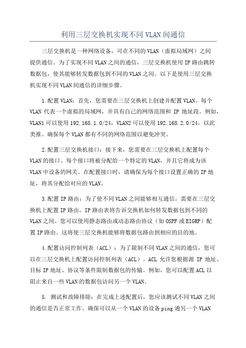
利用三层交换机实现不同VLAN间通信三层交换机是一种网络设备,可在不同的VLAN(虚拟局域网)之间提供通信。
为了实现不同VLAN之间的通信,三层交换机使用IP路由跳转数据包,使其能够转发数据包到不同的VLAN之间。
以下是使用三层交换机实现不同VLAN间通信的详细步骤。
1.配置VLAN:首先,您需要在三层交换机上创建并配置VLAN。
每个VLAN代表一个虚拟的局域网,并具有自己的网络范围和IP地址段。
例如,VLAN1可以使用192.168.1.0/24,VLAN2可以使用192.168.2.0/24,以此类推。
确保每个VLAN都有不同的网络范围以避免冲突。
2.配置三层交换机接口:接下来,您需要在三层交换机上配置每个VLAN的接口。
每个接口将被分配给一个特定的VLAN,并且它将成为该VLAN中设备的网关。
在配置接口时,请确保为每个接口设置正确的IP地址,将其分配给对应的VLAN。
3.配置IP路由:为了使不同VLAN之间能够相互通信,需要在三层交换机上配置IP路由。
IP路由表将告诉交换机如何转发数据包到不同的VLAN之间。
您可以使用静态路由或动态路由协议(如OSPF或EIGRP)配置IP路由。
这将使三层交换机能够将数据包路由到相应的目的地。
4.配置访问控制列表(ACL):为了限制不同VLAN之间的通信,您可以在三层交换机上配置访问控制列表(ACL)。
ACL允许您根据源IP地址、目标IP地址、协议等条件限制数据包的传输。
例如,您可以配置ACL以阻止来自一些VLAN的数据包访问另一个VLAN。
5. 测试和故障排除:在完成上述配置后,您应该测试不同VLAN之间的通信是否正常工作。
确保可以从一个VLAN的设备ping通另一个VLAN的设备,并能够执行其他网络活动(如文件共享或服务访问)。
如果发现问题,可以使用工具如抓包软件(Wireshark)来检查数据包流量,查找潜在的故障原因。
通过以上步骤,您可以利用三层交换机实现不同VLAN之间的通信。
三层交换机实现VLAN间通信

三层交换机实现VLAN间通信现代企业网络中,为了有效管理网络资源和提高网络安全性,常常会对网络进行VLAN 划分。
VLAN(Virtual Local Area Network)是一种逻辑上的局域网络,通过VLAN可以将不同物理位置上的设备组成一个逻辑上的局域网络,从而实现更好的管理和安全控制。
而在实际的网络中,为了不同VLAN间的通信,需要借助三层交换机来实现VLAN间通信。
本文将详细介绍三层交换机实现VLAN间通信的原理和方法。
一、三层交换机的作用在传统的网络中,二层交换机主要负责交换数据帧,根据目标MAC地址将数据帧转发到正确的端口,但它并不理解IP地址和路由信息。
而三层交换机则结合了交换机和路由器的功能,不仅能够根据MAC地址进行转发,还能够根据IP地址和路由表实现数据包的转发和路由选择。
三层交换机在实现VLAN间通信时起到了至关重要的作用。
在VLAN划分的网络中,不同的VLAN被视为不同的逻辑网络,它们之间默认是无法直接通信的。
三层交换机的作用就是要实现不同VLAN之间的通信,它可以基于VLAN和IP地址实现不同VLAN之间的数据包转发。
具体原理如下:1. VLAN划分:需要在三层交换机上进行VLAN的配置,将不同的端口划分到不同的VLAN中,这样可以确保不同VLAN中的设备被隔离开。
2. 路由表配置:接下来,需要在三层交换机上配置路由表,将不同VLAN的IP子网和相应的接口关联起来,这样可以使得三层交换机能够理解不同VLAN之间的路由信息。
3. 跨VLAN通信:通过配置交换机的接口,使得不同VLAN上的设备可以通过三层交换机进行通信。
在数据包进入三层交换机的端口时,根据路由表上的信息,可以将数据包转发到正确的VLAN,并最终实现不同VLAN间的通信。
接下来,我们将详细介绍如何在三层交换机上进行VLAN间通信的配置。
以下以思科公司的三层交换机为例进行说明。
1. 配置VLAN#进入交换机全局模式Switch>enableSwitch#conf t#创建VLAN 10Switch(config)#vlan 10Switch(config-vlan)#name VLAN10Switch(config-vlan)#exit#创建VLAN 20Switch(config)#vlan 20Switch(config-vlan)#name VLAN20Switch(config-vlan)#exit#配置端口划分到不同的VLANSwitch(config)#interface fastethernet 0/1Switch(config-if)#switchport mode accessSwitch(config-if)#switchport access vlan 10Switch(config-if)#exitSwitch(config)#interface fastethernet 0/2Switch(config-if)#switchport mode accessSwitch(config-if)#switchport access vlan 20Switch(config-if)#exit3. 配置跨VLAN通信Switch(config)#interface fastethernet 0/3Switch(config-if)#switchport mode trunkSwitch(config-if)#switchport trunk allowed vlan 10,20Switch(config-if)#exit四、总结通过三层交换机的VLAN间通信配置,可以实现不同VLAN之间的数据包转发和通信,使得不同VLAN中的设备能够相互访问和通信,同时又能够保持彼此的隔离。
思科三层交换机VLAN+NAT+静态路由(已经修改过的)

一台思科三层交换机划分两个VLAN 其中VLAN2 IP地址为 192.168.1.1 子网掩码 255.255.255.0 另外一个VLAN3 IP地址为 192.168.2.1 子网掩码255.255.255.0 三层交换机的F0/2接口绑定到VLAN2中而三层交换机F0/3口绑定到对应的VLAN3中而三层交换机F0/2口下面连了一台思科的二层交换机的F0/1口而三层交换机F0/3口下面也连了一台思科二层交换机F0/1口 F0/2口下面连的二层交换机所有的24个端口都养绑定到VLAN2里面而F0/3口下面的二层交换机所有的24个端口都养绑定到VLAN3里面,当然要求两台交换机都要能够互相PING通对方!同时也要求三层交换机和二层交换机全部都要开启telnet功能方便以后通过电脑可以远程管理交换机!同时思科三层交换机的F0/1口还连着一台思科路由器!思科路由器做NAT 和端口映射!要求二层交换机连着的那些电脑都能够通过这台思科路由器上因特网,并且服务器通过端口映射可以让因特网的电脑访问到这些服务器具体网络拓扑结构如下图首先在三层交换机上做如下操作!C3550>enableC3550#vlan databaseC3550(vlan)#vlan 2C3550(vlan)#vlan 3C3550(vlan)#exitC3550#conf tC3550(config)#int f0/2C3550(config-if)#switchport mode accessC3550(config-if)#switchport access vlan 2C3550(config-if)#no shut downC3550(config-if)#int f0/3C3550(config-if)#switchport mode accessC3550(config-if)#switchport access vlan 3C3550(config-if)#no shut downC3550(config-if)#exitC3550(config)#int vlan 2C3550(config-if)#ip address 192.168.1.1 255.255.255.0 C3550(config-if)#int vlan 3C3550(config-if)#ip address 192.168.2.1 255.255.255.0 C3550(config-if)#exitC3550(config)#ip routingC3550(config)#endC3550(config)#int f0/2C3550(config-if)#switchport mode trunkC3550(config-if)#switchport trunk encapsulation dot1q C3550(config-if)#switchport trunk allowed vlan allC3550(config)#int f0/3C3550(config-if)#switchport mode trunkC3550(config-if)#switchport trunk encapsulation dot1q C3550(config-if)#switchport trunk allowed vlan allC3550#vlan databaseC3550(vlan)#vtp serverC3550(vlan)#vtp domain ntC3550(vlan)#vtp password 123C3550(vlan)#exitC3550#conf tC3550 (config)#line vty 0 4C3550 (config-line)#password 123C3550 (config-line)#loginC3550 (config-line)#exitC3550#copy running-config startup-config然后在二层交换机上做如下操作C2900>enableC2900#vlan databaseC2900(vlan)#vtp clientC2900(vlan)#vtp domain ntC2900(vlan)#vtp password 123C2900(vlan)#exitC2900#config tC2900(config)#int f0/1C2900(config-if)#switchport mode trunkC2900(config-if)#switchport trunk encapsulation dot1q C2900(config-if)#switchport trunk allowed vlan allC2900(config-if)#no shut downC2900(config)#int range f0/2 -24C2900(config-if)#switchport mode accessC2900(config-if)#switchport access vlan 2C2900(config-if)#exitC2900(config)#int vlan 2C2900(config-if)#ip address 192.168.1.200 255.255.255.0 C2900(config-if)#ip default-gateway 192.168.1.1C2900(config)#line vty 0 4C2900 (config-line)#password 123C2900 (config-line)#loginC2900 (config-line)#exitC2900#copy running-config startup-config在另外一台二层交换机上做如下操作C2900>enableC2900#vlan databaseC2900(vlan)#vtp clientC2900(vlan)#vtp domain ntC2900(vlan)#vtp password 123C2900(vlan)#exitC2900#config tC2900(config)#int f0/1C2900(config-if)#switchport mode trunkC2900(config-if)#switchport trunk encapsulation dot1qC2900(config-if)#switchport trunk allowed vlan allC2900(config-if)#no shut downC2900(config)#int range f0/2 -24C2900(config-if)#switchport mode accessC2900(config-if)#switchport access vlan 3C2900(config-if)#no shut downC2900(config-if)#exitC2900(config)#int vlan 3C2900(config-if)#ip address 192.168.2.200 255.255.255.0 C2900(config-if)#ip default-gateway 192.168.2.1C2900(config)#line vty 0 4C2900 (config-line)#password 123C2900 (config-line)#loginC2900 (config-line)#exitC2900#copy running-config startup-config接着再回到三层交换机上做如下操作C3550>enableC3550#conf tC3550(config)#int f0/1C3550(config)#no switchportC3550(config-if)#ip address 192.168.3.1 255.255.255.0C3550(config-if)#exitC3550#copy running-config startup-config接着到路由器上做如下操作(假设找ISP申请了三个外网IP地址 202.99.96.63 202.99.96.64 202.99.96.65 子网掩码255.255.255.248 统一用202.99.96.63这个外网IP上因特网R1>enableR1#config tR1(config)#int f0/0R1(config-if)#ip address 192.168.3.2 255.255.255.0R1(config-if)#ip nat insideR1(config-if)#no shut downR1(config-if)#exitR1(config)#ip route 192.168.1.0 255.255.255.0 192.168.3.1R1(config)#ip route 192.168.2.0 255.255.255.0 192.168.3.1R1(config)int s0/0R1(config-if)#ip address 202.99.96.63 255.255.255.248R1(config-if)#no shut downR1(config-if)#ip nat outsideR1(config-if)#exitR1(config)#ip nat pool nt 202.99.96.63 202.99.96.65R1(config)#access-list 1 permit 192.168.1.0 0.0.0.255R1(config)#access-list 2 permit 192.168.2.0 0.0.0.255R1(config)#access-list 3 permit 192.168.3.0 0.0.0.255R1(config)#ip nat inside source list 1 pool nt overloadR1(config)#ip nat inside source list 2 pool nt overloadR1(config)#ip nat inside source list 3 pool nt overloadR1(config)#ip route 0.0.0.0 0.0.0.0 s0/0R1(config)#line vty 0 4R1 (config-line)#password 123R1 (config-line)#loginR1(config-line)#exit此外局域网中还有一个80端口的WEB服务器还有一个21端口的FTP服务器需要把这两个服务器做端口映射映射到因特网上!R1(config)#ip nat inside source static tcp 192.168.1.200 80202.99.96.63 80R1(config)#ip nat inside source static tcp 192.168.1.201 21202.99.96.63 21R1(config)#exitR1#copy running-config startup-config最后回到三层交换机做一下操作C3550 (config)#ip route 0.0.0.0 0.0.0.0 192.168.3.2C3550#copy running-config startup-config所有的操作都已经完成了!以上所有的操作都是本人自己总结的!也是自己写的!请问我完成了以上的那些操作之后是否可以达到我刚开始说的那些要求!如果可以达到我刚开始说的那些要求的话请说出为什么能达到!没有命令是错误的?如果不可以达到我刚开始说的那些要求的话请说出为什么不能达到!请问还有哪些命令是错误的呢?请写出具体正确的命令!谢谢!Inter vlan 2Ip address 192.168.1.200 255.255.255.0Ip default-gateway 192.168.1.1Inter vlan 3Ip address 192.168.2.200 255.255.255.0Ip default-gateway 192.168.2.1。
2、思科模拟器 实验二(三层交换机VLAN配置)hao
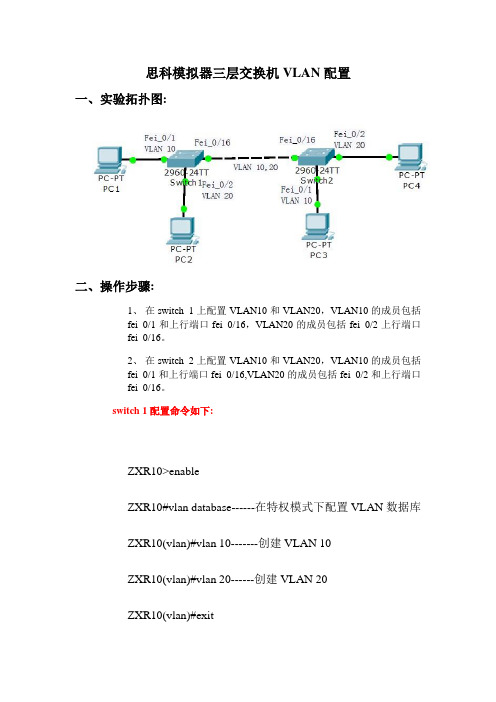
思科模拟器三层交换机VLAN配置一、实验拓扑图:交换机switch 1的端口fei_0/1和交换机switch 2的端口fei_0/1属于VLAN 10;交换机switch 1的端口fei_0/2和交换机switch 2的端口fei_0/2属于VLAN 20,均为Access端口。
两台交换机通过端口fei_0/16以Trunk方式连接,两端口为Trunk端口。
二、操作步骤:1、在switch 1上配置VLAN10和VLAN20,VLAN10的成员包括fei_0/1和上行端口fei_0/16,VLAN20的成员包括fei_0/2上行端口fei_0/16。
2、在switch 2上配置VLAN10和VLAN20,VLAN10的成员包括fei_0/1和上行端口fei_0/16,VLAN20的成员包括fei_0/2和上行端口fei_0/16。
switch 1配置命令如下:ZXR10>enableZXR10#vlan database------在特权模式下配置VLAN数据库ZXR10(vlan)#vlan 10-------创建VLAN 10ZXR10(vlan)#vlan 20------创建VLAN 20ZXR10(vlan)#exitZXR10#configure terminalZXR10(config)#1、进入端口fei_0/1,把端口fei_0/1加入vlan 10,fei_0/1模式为access;ZXR10(config)#interface fastethernet 0/1ZXR10(config-if)#switchport mode accessZXR10(config-if)#switchport access vlan 10ZXR10(config-if)#exit2、进入端口fei_0/2,把端口fei_0/2加入vlan 20,fei_0/2模式为access;ZXR10(config)#interface fastethernet 0/2ZXR10(config-if)#switchport mode accessZXR10(config-if)#switchport access vlan 20ZXR10(config-if)#exit3、进入fei_0/16端口,将该端口设置成trunk模式,并且把端口fei_0/16以trunk模式加入vlan10,vlan 20ZXR10(config)#interface fastethernet 0/16ZXR10(config-if)#switchport mode trunkZXR10(config-if)#switchport trunk allowed vlan 10,20ZXR10(config-if)#endZXR10#write---------保存文件(备注:switch 2配置命令同switch 1一样)三、验证方法:1. PC-1和PC-2不能互通,PC-3和PC-4不能互通2. PC-1和PC-3互通,PC-2和PC-4互通。
三层交换机划分个vlan实现其互相通迅

综合实验一台思科三层交换机划分3个vlanvlan2:ip网段vlan3:ipvlan4ip各vlan之间能互相通迅.现在增加1台cisco路由想实现共享我们的PC0、PC1处在VLAN2中,PC2、PC3处在VLAN3中,Server0处在VLAN4中;现在要使我们内网能够正常访问我们的Server0服务器,然后同时还要能够访问我们的ISP外网的服务器;三层交换机的配置SwitchconfigtSwitchconfig vlan2创建VLAN2Switchconfig-vlan exiSwitchconfig vlan3创建VLAN3Switchconfig-vlan exiSwitchconfig vlan4创建VLAN4Switchconfig-vlan exitSwitchconfig intfa0/2将我们的fa0/2添加到VLAN2中Switchconfig-if swmoacSwitchconfig-if swacvlan2Switchconfig-if exitSwitchconfig intfa0/3将我们的FA0/3添加到VLAN3中Switchconfig-if swmoacSwitchconfig-if swacvlan3Switchconfig-if exitSwitchconfig intfa0/4将我们的FA0/4添加到VLAN4中Switchconfig-if swmoacSwitchconfig-if swacvlan4Switchconfig-if exitSwitchconfig intvlan2给我们的VLAN2添加一个IP地址,用于不同网段之间互相访问Switchconfig-if ipaddSwitchconfig-if exitSwitchconfig intvlan3给我们的VLAN3添加一个IP地址Switchconfig-if ipaddSwitchconfig-if exitSwitchconfig intvlan4给我们的VLAN4添加一个IP地址Switchconfig-if ipaddSwitchconfig-if noshutSwitchconfig-if exit以下几行是用来给我们不同的VLAN内的主机自动分配我们的IP地址; Switchconfig ipdhcppoolVLAN2Switchdhcp-config networkSwitchdhcp-config default-routerSwitchdhcp-config exitSwitchconfig ipdhcppoolVLAN3Switchdhcp-config network192.168.2.0Switchdhcp-config default-routerSwitchdhcp-config exitSwitchconfigSwitchconfig intfa0/24Switchconfig-if noswitchport关闭二层端口,这样就可以配置IP地址了Switchconfig-if ipadd它现在是一个三层端口,它可以配置IP地址Switchconfig-if noshutSwitchconfig-if exitSwitchconfig iprouting开启路由功能,如果不开启路由功能就不能使用路由协议Switchconfig routerrip我们这里运行一个rip协议Switchconfig-router ver2Switchconfig-router noauSwitchconfig-router netSwitchconfig-router netSwitchconfig-router netSwitchconfig-router netSwitchconfig-router exitSwitchconfig路由器的配置fa0/0Routerconfig-router default-informationoriginate它的作用是给我们三层路由器分配一条默认路由出去Routerconfig-router exitRouterconfigRouterconfig access-list1permit0.0.0.255Routerconfig access-list1permitRouterconfig access-list1permitRouterconfig ipnatinsidesourcelist1interfaces0/0overloadRouterconfig ints0/0Routerconfig-if ipnatout sideRouterconfig-if exitRouterconfig intfa0/0Routerconfig-if ipnatinsideRouterconfig-if endRouterconfig iproutes0/0ISP端路由器的配置Router conftRouterconfig hostISP ISPconfig ints0/0ISPconfig-if ipadd ISPconfig-if noshut ISPconfig-if clockrate64000 ISPconfig-if exitISPconfig intfa0/0 ISPconfig-if ipadd ISPconfig-if noshut ISPconfig-if exitISPconfig。
思科设备三层交换机的vlan间通信配置
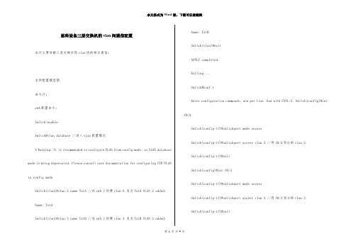
思科设备三层交换机的vlan间通信配置本次主要讲解三层交换实现vlan间的相互通信:本例配置模型图命令行:swA配置命令:Switch>enableSwitch#vlan database //进入vlan配置模式% Warning: It is recommended to configure VLAN from config mode, as VLAN database mode is being deprecated. Please consult user documentation for configuring VTP/VLAN in config mode.Switch(vlan)#vlan 2 name TztA //在swA上创建vlan 2 名为TztA VLAN 2 added: Name: TztASwitch(vlan)#vlan 3 name TztB //在swA上创建vlan 3 名为TztB VLAN 3 added: Name: TztBSwitch(vlan)#exitAPPLY completed.Exiting....Switch#conf tEnter configuration commands, one per line. End with CNTL/Z. Switch(config)#int f0/2Switch(config-if)#switchport mode accessSwitch(config-if)#switchport access vlan 2 //将f0/2划分给vlan 2Switch(config-if)#exitSwitch(config)#int f0/3Switch(config-if)#switchport mode accessSwitch(config-if)#switchport access vlan 3 //将f0/3划分给vlan 3Switch(config-if)#exitSwitch(config)#int f0/1Switch(config-if)#switchport mode trunk //配置与三层设备连接的f0/1为trunk模式%LINEPROTO-5-UPDOWN: Line protocol on Interface FastEthernet0/1, changed state to down%LINEPROTO-5-UPDOWN: Line protocol on Interface FastEthernet0/1, changed state to upSwitch(config-if)#switchport trunk allowed vlan all //允许所有vlan通过f0/1端口Switch(config-if)#exitSwitch(config)#exitSwitch#%SYS-5-CONFIG_I: Configured from console by consoleSwitch#wrBuilding configuration... [OK]Switch#(三层交换机)M sw命令配置:Switch>Switch>enableSwitch#vlan database //进入vlan配置模式% Warning: It is recommended to configure VLAN from config mode, as VLAN database mode is being deprecated. Please consult user documentation for configuring VTP/VLAN in config mode.Switch(vlan)#vlan 2 name TztA //在Msw上创建vlan 2 名为TztAVLAN 2 added:Name: TztASwitch(vlan)#vlan 3 name TztB //在Msw上创建vlan 2 名为TztAVLAN 3 added:Name: TztBSwitch(vlan)#exitAPPLY completed.Exiting....Switch#conf tEnter configuration commands, one per line. End with CNTL/Z.Switch(config)#int f0/1Switch(config-if)#switchport mode trunk //配置三层设备与二层设备连接的f0/1为trunk模式Command rejected: An interface whose trunk encapsulation is "Auto" can not be configured to "trunk" mode.Switch(config-if)#switchport trunk allowed vlan all //允许所有vlan通过f0/1端口Switch(config-if)#no shutdown //激活端口Switch(config-if)#exit Switch(config)#ip routing //使用三层设备的路由功能Switch(config)#int vlan 2 //进入vlan 2配置模式虚拟端口%LINK-5-CHANGED: Interface Vlan2, changed state to upSwitch(config-if)#%LINEPROTO-5-UPDOWN: Line protocol on Interface Vlan2, changed state to up Switch(config-if)#ip address 192.168.1.1 255.255.255.0 //配置vlan 2的ip地址Switch(config-if)#no shutdown //激活端口Switch(config-if)#exitSwitch(config)#int vlan 3 //配置vlan 3虚拟端口Switch(config-if)#%LINK-5-CHANGED: Interface Vlan3, changed state to up%LINEPROTO-5-UPDOWN: Line protocol on Interface Vlan3, changed state to up Switch(config-if)#ip address 192.168.2.1 255.255.255.0Switch(config-if)#no shutdownSwitch(config-if)#exitSwitch(config)#do show ip routeCodes: C - connected, S - static, I - IGRP, R - RIP, M - mobile, B - BGPD - EIGRP, EX - EIGRP external, O - OSPF, IA - OSPF inter areaN1 - OSPF NSSA external type 1, N2 - OSPF NSSA external type 2E1 - OSPF external type 1, E2 - OSPF external type 2, E - EGPi - IS-IS, L1 - IS-IS level-1, L2 - IS-IS level-2, ia - IS-IS inter area * - candidate default, U - per-user static route, o - ODRP - periodic downloaded static routeGateway of last resort is not setC 192.168.1.0/24 is directly connected, Vlan2 //上述的配置成果C 192.168.2.0/24 is directly connected, Vlan3Switch(config)#Switch(config)#exit Switch#%SYS-5-CONFIG_I: Configured from console by console Switch#wrBuilding configuration...[OK]以上配置结束完成后,两台PC能够相互通信(如图):注意:通信基础需要配置网关本次讲解结束!。
- 1、下载文档前请自行甄别文档内容的完整性,平台不提供额外的编辑、内容补充、找答案等附加服务。
- 2、"仅部分预览"的文档,不可在线预览部分如存在完整性等问题,可反馈申请退款(可完整预览的文档不适用该条件!)。
- 3、如文档侵犯您的权益,请联系客服反馈,我们会尽快为您处理(人工客服工作时间:9:00-18:30)。
本次主要讲解三层交换实现vlan间的相互通信:
本例配置模型图
命令行:
swA配置命令:
Switch>enable
Switch#vlan database //进入vlan配置模式
% Warning: It is recommended to configure VLAN from config mode, as VLAN database mode is being deprecated. Please consult user documentation for configuring VTP/VLAN in config mode.
Switch(vlan)#vlan 2 name TztA //在swA上创建vlan 2 名为TztA VLAN 2 added:
Name: TztA
Switch(vlan)#vlan 3 name TztB //在swA上创建vlan 3 名为TztB VLAN 3 added:
Name: TztB
Switch(vlan)#exit
APPLY completed.
Exiting....
Switch#conf t
Enter configuration commands, one per line. End with CNTL/Z. Switch(config)#int f0/2
Switch(config-if)#switchport mode access
Switch(config-if)#switchport access vlan 2 //将f0/2划分给vlan 2
Switch(config-if)#exit
Switch(config)#int f0/3
Switch(config-if)#switchport mode access
Switch(config-if)#switchport access vlan 3 //将f0/3划分给vlan 3
Switch(config-if)#exit
Switch(config)#int f0/1
Switch(config-if)#switchport mode trunk //配置与三层设备连接的f0/1为trunk模式
%LINEPROTO-5-UPDOWN: Line protocol on Interface FastEthernet0/1, changed state to down
%LINEPROTO-5-UPDOWN: Line protocol on Interface FastEthernet0/1, changed state to up
Switch(config-if)#switchport trunk allowed vlan all //允许所有vlan通过f0/1端口Switch(config-if)#exit
Switch(config)#exit
Switch#
%SYS-5-CONFIG_I: Configured from console by console
Switch#wr
Building configuration...
[OK]
Switch#
(三层交换机)M sw命令配置:
Switch>
Switch>enable
Switch#vlan database //进入vlan配置模式
% Warning: It is recommended to configure VLAN from config mode,
as VLAN database mode is being deprecated. Please consult user
documentation for configuring VTP/VLAN in config mode.
Switch(vlan)#vlan 2 name TztA //在Msw上创建vlan 2 名为TztA
VLAN 2 added:
Name: TztA
Switch(vlan)#vlan 3 name TztB //在Msw上创建vlan 2 名为TztA
VLAN 3 added:
Name: TztB
Switch(vlan)#exit
APPLY completed.
Exiting....
Switch#conf t
Enter configuration commands, one per line. End with CNTL/Z.
Switch(config)#int f0/1
Switch(config-if)#switchport mode trunk //配置三层设备与二层设备连接的f0/1为trunk模式
Command rejected: An interface whose trunk encapsulation is "Auto" can not be configured to "trunk" mode.
Switch(config-if)#switchport trunk allowed vlan all //允许所有vlan通过f0/1端口Switch(config-if)#no shutdown //激活端口
Switch(config-if)#exit
Switch(config)#ip routing //使用三层设备的路由功能
Switch(config)#int vlan 2 //进入vlan 2配置模式虚拟端口
%LINK-5-CHANGED: Interface Vlan2, changed state to up
Switch(config-if)#
%LINEPROTO-5-UPDOWN: Line protocol on Interface Vlan2, changed state to up
Switch(config-if)#ip address 192.168.1.1 255.255.255.0 //配置vlan 2的ip地址Switch(config-if)#no shutdown //激活端口
Switch(config-if)#exit
Switch(config)#int vlan 3 //配置vlan 3虚拟端口
Switch(config-if)#
%LINK-5-CHANGED: Interface Vlan3, changed state to up
%LINEPROTO-5-UPDOWN: Line protocol on Interface Vlan3, changed state to up
Switch(config-if)#ip address 192.168.2.1 255.255.255.0
Switch(config-if)#no shutdown
Switch(config-if)#exit
Switch(config)#do show ip route
Codes: C - connected, S - static, I - IGRP, R - RIP, M - mobile, B - BGP
D - EIGRP, EX - EIGRP external, O - OSPF, IA - OSPF inter area
N1 - OSPF NSSA external type 1, N2 - OSPF NSSA external type 2
E1 - OSPF external type 1, E2 - OSPF external type 2, E - EGP
i - IS-IS, L1 - IS-IS level-1, L2 - IS-IS level-2, ia - IS-IS inter area * - candidate default, U - per-user static route, o - ODR
P - periodic downloaded static route
Gateway of last resort is not set
C 192.168.1.0/24 is directly connected, Vlan2 //上述的配置成果
C 192.168.2.0/24 is directly connected, Vlan3
Switch(config)#
Switch(config)#exit
Switch#
%SYS-5-CONFIG_I: Configured from console by console
Switch#wr
Building configuration...
[OK]
以上配置结束完成后,两台PC能够相互通信(如图):
注意:通信基础需要配置网关
本次讲解结束!。