VLAN(三层交换机)配置
三层交换机实现VLAN间路由

三层交换机实现VLAN间路由一、如图所示连接各设备二、如图所示配置主机IP地址三、配置交换机switch1和交换机switch2,创建VLAN 10 ,VLAN 11 和VLAN 12 Switch1的配置:Switch1#conf tSwitch1(config)#vlan 10Switch1(config-vlan)#name xiaoshouSwitch1(config-vlan)#exitSwitc1h(config)#vlan 11Switch1(config-vlan)#name tuiguangSwitch1(config-vlan)#exitSwitch1(config)#vlan 12Switch1(config-vlan)#name caiwuSwitch1(config-vlan)#exitSwitch2的配置:Switch2#conf tSwitch2(config)#vlan 10Switch2(config-vlan)#name xiaoshouSwitch2(config-vlan)#exitSwitch2(config)#vlan 11Switch2(config-vlan)#name tuiguangSwitch2(config-vlan)#exitSwitch2(config)#vlan 12Switch2(config-vlan)#name caiwuSwitch2(config-vlan)#exit四、把相应接口加入对应VLAN中Switch1的配置:Switch1(config)#int fa 0/1Switch1(config-if)#switchport access vlan 10Switch1(config-if)#exitSwitch1(config)#interface fastEthernet 0/2Switch1(config-if)#switchport access vlan 11Switch1(config-if)#exitSwitch2的配置:Switch2(config)#int fa 0/1Switch2(config-if)#switchport access vlan 12Switch2(config-if)#exitSwitch2(config)#interface fastEthernet 0/2Switch2(config-if)#switchport access vlan 10Switch2(config-if)#exit五、配置switch1的fa 0/23接口,switch2的fa 0/24接口和三层交换机switch0的fa 0/23和fa 0/24接口为trunk模式Switch1(config)#inter fa 0/23Switch1(config-if)#switch mode trunkSwitch2(config)#inter fa 0/24Switch2(config-if)#switch mode trunkSwitch0(config)#inter fa0/23Switch0(config-if)#switch mode trunkSwitch0(config-if)#exitSwitch0(config)#inter fa0/24Switch0(config-if)#switch mode trunkSwitch0(config-if)#exit六、在三层交换机switch0上开启路由功能Switch0>enableSwitch0#conf tSwitch0(config)#ip routing七、在三层交换机switch0上创建相应vlan 10 ,vlan 11和vlan 12Switch0(config)#vlan 10Switch0(config-vlan)#vlan 11Switch0(config-vlan)#vlan 12Switch0(config-vlan)#exit八、在三层交换机switch0上配置和启用svi接口:Switch0(config)#interface vlan 10Switch0(config-if)#ip add 192.168.1.254 255.255.255.0Switch0(config-if)#no shutdownSwitch0(config)#interface vlan 11Switch0(config-if)#ip add 192.168.2.254 255.255.255.0Switch0(config-if)#no shutdownSwitch0(config)#interface vlan 12Switch0(config-if)#ip add 192.168.3.254 255.255.255.0Switch0(config-if)#no shutdown九、配置各主机的网关为对应svi接口的地址十、销售部电脑ping 推广部电脑结果十一、PING通,结果验证正确,配置成功。
vlan的配置方法

vlan的配置方法VLAN(Virtual Local Area Network,虚拟局域网)是一种将一个物理网络划分成多个逻辑上的虚拟网络的技术,它可以提供更好的网络性能、安全性和管理灵活性。
在进行VLAN的配置时,需要按照一定的步骤进行操作,下面将详细介绍VLAN的配置方法。
1. 确定VLAN的划分方案在配置VLAN之前,需要先确定VLAN的划分方案。
可以根据不同的需求和网络拓扑结构,将网络划分为不同的VLAN,如按照部门、功能或地理位置等进行划分。
确定划分方案后,可以开始进行VLAN的配置。
2. 创建VLAN在交换机上创建VLAN是配置VLAN的第一步。
可以通过以下命令在交换机上创建VLAN:```Switch(config)# vlan vlan_id```其中,vlan_id为VLAN的标识符,可以根据实际需求进行设置。
创建VLAN后,可以通过以下命令查看已创建的VLAN列表:```Switch# show vlan```3. 配置接口创建VLAN后,需要将交换机的接口与相应的VLAN进行关联。
可以通过以下命令将接口划分到指定的VLAN:```Switch(config)# interface interface_idSwitch(config-if)# switchport mode accessSwitch(config-if)# switchport access vlan vlan_id```其中,interface_id为接口的标识符,可以是物理接口、端口通道或VLAN接口。
vlan_id为要划分到的VLAN的标识符。
配置完成后,可以通过以下命令查看接口的VLAN配置情况:```Switch# show interfaces interface_id switchport```4. 配置Trunk接口如果需要在不同的交换机之间传输多个VLAN的数据,就需要配置Trunk接口。
cisco三层交换机vlan间路由配置实例
cisco三层交换机vlan间路由配置实例下面以cisco3560实例说明如何在一个典型的快速以太局域网中实现VLAN。
所谓典型局域网就是指由一台具备三层交换功能的核心交换机接几台分支交换机(不一定具备三层交换能力)。
我们假设核心交换机名称为:COM;分支交换机分别为:PAR1、PAR2、PAR3,分别通过Port 1的光线模块与核心交换机相连;并且假设VLAN名称分别为COUNTER、MARKET、MANAGING……需要做的工作:1、设置VTP DOMAIN(核心、分支交换机上都设置)2、配置中继(核心、分支交换机上都设置)3、创建VLAN(在server上设置)4、将交换机端口划入VLAN5、配置三层交换1、设置VTP DOMAIN。
VTP DOMAIN 称为管理域。
交换VTP更新信息的所有交换机必须配置为相同的管理域。
如果所有的交换机都以中继线相连,那么只要在核心交换机上设置一个管理域,网络上所有的交换机都加入该域,这样管理域里所有的交换机就能够了解彼此的VLAN列表。
COM#vlan database 进入VLAN配置模式COM(vlan)#vtp domain COM 设置VTP管理域名称 COMCOM(vlan)#vtp server 设置交换机为服务器模式PAR1#vlan database 进入VLAN配置模式PAR1(vlan)#vtp domain COM 设置VTP管理域名称COMPAR1(vlan)#vtp Client 设置交换机为客户端模式PAR2#vlan database 进入VLAN配置模式PAR2(vlan)#vtp domain COM 设置VTP管理域名称COMPAR2(vlan)#vtp Client 设置交换机为客户端模式PAR3#vlan database 进入VLAN配置模式PAR3(vlan)#vtp domain COM 设置VTP管理域名称COMPAR3(vlan)#vtp Client 设置交换机为客户端模式注意:这里设置核心交换机为Server模式是指允许在该交换机上创建、修改、删除VLAN 及其他一些对整个VTP域的配置参数,同步本VTP域中其他交换机传递来的最新的VLAN 信息;Client模式是指本交换机不能创建、删除、修改VLAN配置,也不能在NVRAM中存储VLAN配置,但可同步由本 VTP域中其他交换机传递来的VLAN信息。
三层交换机-vlan间路由配置

需求:
1、设置VTP域
2、配置交换机间中继链路
3、在核心交换机上创建VLAN
4、将交换机端口划入VLAN
5、配置三层交换
1、设置VTP域:
交换VTP更新信息的所有交换机必须配置在相同的管理域,如果所有的交换机都以中继链路相连,则只需在核心交换机上建立一个管理域,网络上所有的交换机都加入该域,且域里所有的交换机就能够彼此学习VLAN信息。
ACC1(config)#interface fastEthernet 0/2
ACC1(config-if)#switchport access vlan 20
ACC1(config)#interface fastEthernet 0/3
ACC1(config-if)#switchport access vlan 30
5、配置三层交换
接下来我们考虑VLAN间如何实现三层交换呢?这就要给各VLAN分配网络IP地址了
如:给VLAN-A分配的接口Ip地址为192.168.10.1/24,网络地址为:192.168.10.0,
VLAN -B 分配的接口Ip地址为192.168.20.1/24,网络地址为:192.168.20.0,
CORE(config-if)#no sh
此后,再在各接入VLAN的计算机上设置与所属VLAN的网络地址一致的IP地址,并且把默认网关设置为该VLAN的接口地址,至此就可以实现VLAN路由了。
在三层交换机开启路由功能:
CORE(config)#ip routing
CORE(config)#interface vlan 10
CORE(config-if)#ip address 192.168.10.1 255.255.255.0
三层交换机怎么设置VLAN间路由.doc

三层交换机怎么设置VLAN间路由方法步骤1、首先打开思科模拟器软件,找出一台三层交换机和两台PC2、将三层交换机和两台PC用直通线连接起来3、在三层交换机上划分VLAN,命令是:复制内容到剪贴板Switch#conf tEnter configuration commands, one per line. End with CNTL/Z.Switch(config)#vlan 2Switch(config-vlan)#exitSwitch(config)#intf0/5Switch(config-if)#switchport mode access Switch(config-if)#switchport access vlan 1Switch(config-if)#int f0/6Switch(config-if)#switchport mode access Switch(config-if)#switchport access vlan 24、开启三层交换机的三层交换路由功能,命令是:ip routing5、给PC配置IP地址和网关6、进入三层交换机里面配置VLAN,命令是:复制内容到剪贴板Switch(config)#int vlan 1Switch(config-if)#noshutSwitch(config-if)#ip add 172.16.10.1 255.255.255.0Switch(config-if)#int vlan 2 Switch(config-if)#no shutSwitch(config-if)#ip add 172.16.20.1 255.255.255.07、利用ping命令对PC之间进行通信测试,可以ping通的结果补充:交换机基本使用方法作为基本核心交换机使用,连接多个有线设备使用:网络结构如下图,基本连接参考上面的【方法/步骤1:基本连接方式】作为网络隔离使用:对于一些功能好的交换机,可以通过模式选择开关选择网络隔离模式,实现网络隔离的作用,可以只允许普通端口和UPlink端口通讯,普通端口之间是相互隔离不可以通讯的除了作为核心交换机(中心交换机)使用,还可以作为扩展交换机(接入交换机)来扩展网络放在路由器上方,扩展网络供应商的网络线路(用于一条线路多个IP的网络),连接之后不同的路由器用不同的IP连接至公网相关阅读:交换机硬件故障常见问题电源故障:由于外部供电不稳定,或者电源线路老化或者雷击等原因导致电源损坏或者风扇停止,从而不能正常工作。
实验报告—VLAN间路由与三层交换机配置

实验:VLAN间路由配置
移动1331 43 林观科
⏹实验目的
1、掌握三层交换机的工作原理
2、学习配置三层交换机的命令和步骤
⏹实验要求
1、拓扑与地址规划;
2、三层交换机和VTP基本配置
3、验证连通性,并给出配置清单
⏹实验拓扑
⏹实验设备(环境、软件)
三层交换机1台,交换机2台,直通线7条,Pc机4台。
软件:GNS3模拟器
⏹实验设计到的基本概念和理论
将三层交换机配置成VTP的server,其他普通交换机配置成VTP CLIENT mode,从而实现各个vlan间的通信。
⏹实验过程和主要步骤
1、绘制网络拓扑和地址规划
地址规划如下:
2、Switch1的配置情况如下所示:
3、Switch2的配置情况如下所示:
4、Router1的配置情况如下所示:
5、显示路由器Router1上的路由表如下:
6、验证4个PC间通信状况
PC1到PC0的通信,PC1到PC2的通信,PC1到PC3的通信状况如下:
总结:
通过这次的实验,我懂得了如何实际地配置三层交换机的简单命令,从而实现不同vlan间的通信,同时深入的了解了路由器在不同区域间的进行通信的重要性。
知道的子接口与路由器中实际的接口的区别与联系,接口是路由器的实际物理接口,而子接口是路由器的逻辑接口(通过GNS3软件实现的),路由器在vlan间实现通信的过程,如何将信息进行传送。
此次实验的过程也不是那么的顺利,但是通过查找有关资料与仔细的看书还有和同学相互讨论才使实验顺利进行,从中了解了不少的知识。
三层交换机+二层交换机VLAN配置

Cisco三层互换机+二层互换机VLAN配备Cisco旳VLAN实现一般是以端口为中心旳。
与节点相连旳端口将拟定它所驻留旳VLAN。
将端口分派给VLAN旳方式有两种,分别是静态旳和动态旳. 形成静态VLAN旳过程是将端口强制性地分派给VLAN旳过程。
即我们先在VTP (VLAN Trunking Protocol)Ser ver上建立VLAN,然后将每个端口分派给相应旳VLAN旳过程。
这是我们创立VLAN最常用旳措施。
ﻫ动态VLAN形成很简朴,由端口决定自己属于哪个VLAN。
即我们先建立一种VMPS(VLANMembershipPolicy Server)VLA N管理方略服务器,里面涉及一种文本文献,文献中存有与VLAN映射旳MAC地址表。
互换机根据这个映射表决定将端口分派给何种VLAN。
这种措施有很大旳优势,但是创立数据库是一项非常艰苦并且非常繁琐旳工作。
ﻫ下面以实例阐明如何在一种典型旳迅速以太局域网中实现VLAN。
所谓典型旳局域网就是指由一台具有三层互换功能旳核心互换机接几台分支互换机(不一定具有三层互换能力)。
我们假设核心互换机名称为:COM;分支互换机分别为:PAR1、PAR2、PAR3……,分别通过Port1旳光线模块与核心互换机相连;并且假设VLAN名称分别为COUNTER、MARKET、MANAGING……。
1、设立VTP DOMAINﻫﻫ称为管理域。
互换VTP更新信息旳所有交换机必须配备为相似旳管理域。
如果所有旳互换机都以中继线相连,那么只要在核心互换机上设立一种管理域,网络上所有旳互换机都加入该域,这样管理域里所有旳互换机就可以理解彼此旳VLAN 列表。
ﻫﻫCOM#vlandatabase进入VLAN配备模式ﻫCOM(vlan)#vtp domain COM 设立VTP管理域名称COMCOM(vlan)#vtp server 设立互换机为服务器模式PAR1#vlan database 进入VLAN配备模式PAR1(vlan)#vtp domainCOM 设立VTP管理域名称COMPAR1(vlan)#vtp Client 设立互换机为客户端模式ﻫPAR2#vlan database 进入VLAN配备模式PAR2(vlan)#vtp domainCOM 设立VTP管理域名称C OMﻫPAR2(vlan)#vtp Client 设立互换机为客户端模式ﻫPAR3#vlan database 进入VLAN配备模式PAR3(vlan)#vtp domain COM 设立VTP管理域名称COM PAR3(vlan)#vtp Client设立互换机为客户端模式ﻫﻫ注意:这里设立互换机为Server模式是指容许在本互换机上创立、修改、删除VLAN及其他某些对整个VTP域旳配备参数,同步本VTP域中其他互换机传递来旳最新旳VLAN信息;Client模式是指本互换机不能创立、删除、修改VLAN配备,也不能在NVRAM 中存储VLAN配备,但可以同步由本VTP域中其他互换机传递来旳VLAN信息。
H3C三层交换机VLAN配置实例
H3C三层交换机VLAN配置实例H3C三层交换机VLAN配置实例<H3C><H3C>dis cu#sysname H3C#radius scheme system#domain system#acl number 2011rule 0 denyrule 1 permit source 172.16.11.0 0.0.0.255 acl number 2012rule 0 denyrule 1 permit source 172.16.12.0 0.0.0.255 acl number 2013rule 0 denyrule 1 permit source 172.16.13.0 0.0.0.255 acl number 2021rule 0 denyrule 1 permit source 172.16.21.0 0.0.0.255 acl number 2022rule 0 denyrule 1 permit source 172.16.22.0 0.0.0.255 acl number 2023rule 0 denyrule 1 permit source 172.16.23.0 0.0.0.255 acl number 2031rule 0 denyrule 1 permit source 172.16.31.0 0.0.0.255 acl number 2032rule 0 denyrule 1 permit source 172.16.32.0 0.0.0.255 acl number 2033rule 0 denyrule 1 permit source 172.16.33.0 0.0.0.255 acl number 2041rule 0 denyrule 1 permit source 172.16.41.0 0.0.0.255 acl number 2042rule 0 denyrule 1 permit source 172.16.42.0 0.0.0.255 acl number 2043rule 0 denyrule 1 permit source 172.16.43.0 0.0.0.255 acl number 2080rule 0 denyrule 1 permit source 172.16.80.0 0.0.0.255 #vlan 1#vlan 11#vlan 12#vlan 13#vlan 21#vlan 22#vlan 23#vlan 31#vlan 32#vlan 33#vlan 41#vlan 42#vlan 43#vlan 80#interface Aux1/0/0#interface Ethernet1/0/1port link-type hybridport hybrid vlan 1 11 untaggedport hybrid pvid vlan 11packet-filter inbound ip-group 2011 rule 0 packet-filter inbound ip-group 2011 rule 1#interface Ethernet1/0/2port link-type hybridport hybrid vlan 1 12 untaggedport hybrid pvid vlan 12packet-filter inbound ip-group 2012 rule 0 packet-filter inbound ip-group 2012 rule 1 #interface Ethernet1/0/3port link-type hybridport hybrid vlan 1 13 untaggedport hybrid pvid vlan 13packet-filter inbound ip-group 2013 rule 0 packet-filter inbound ip-group 2013 rule 1 #interface Ethernet1/0/4port link-type hybridport hybrid vlan 1 21 untaggedport hybrid pvid vlan 21packet-filter inbound ip-group 2021 rule 0 packet-filter inbound ip-group 2021 rule 1 #interface Ethernet1/0/5port link-type hybridport hybrid vlan 1 22 untaggedport hybrid pvid vlan 22packet-filter inbound ip-group 2022 rule 0 packet-filter inbound ip-group 2022 rule 1 #interface Ethernet1/0/6port link-type hybridport hybrid vlan 1 23 untaggedport hybrid pvid vlan 23packet-filter inbound ip-group 2023 rule 0 packet-filter inbound ip-group 2023 rule 1 #interface Ethernet1/0/7port link-type hybridport hybrid vlan 1 31 untaggedport hybrid pvid vlan 31packet-filter inbound ip-group 2031 rule 0 packet-filter inbound ip-group 2031 rule 1 #interface Ethernet1/0/8port link-type hybridport hybrid vlan 1 32 untaggedport hybrid pvid vlan 32packet-filter inbound ip-group 2032 rule 0 packet-filter inbound ip-group 2032 rule 1 #interface Ethernet1/0/9port link-type hybridport hybrid vlan 1 33 untaggedport hybrid pvid vlan 33packet-filter inbound ip-group 2033 rule 0 packet-filter inbound ip-group 2033 rule 1 #interface Ethernet1/0/10port link-type hybridport hybrid vlan 1 41 untaggedport hybrid pvid vlan 41packet-filter inbound ip-group 2041 rule 0 packet-filter inbound ip-group 2041 rule 1 #interface Ethernet1/0/11port link-type hybridport hybrid vlan 1 42 untaggedport hybrid pvid vlan 42packet-filter inbound ip-group 2042 rule 0 packet-filter inbound ip-group 2042 rule 1 #interface Ethernet1/0/12port link-type hybridport hybrid vlan 1 43 untaggedport hybrid pvid vlan 43packet-filter inbound ip-group 2043 rule 0 packet-filter inbound ip-group 2043 rule 1 #interface Ethernet1/0/13#interface Ethernet1/0/14#interface Ethernet1/0/15#interface Ethernet1/0/16#interface Ethernet1/0/17#interface Ethernet1/0/18#interface Ethernet1/0/19#interface Ethernet1/0/20port link-type hybridport hybrid vlan 1 80 untaggedport hybrid pvid vlan 80packet-filter inbound ip-group 2080 rule 0packet-filter inbound ip-group 2080 rule 1#interface Ethernet1/0/21#interface Ethernet1/0/22port link-type hybridport hybrid vlan 1 11 to 13 21 to 23 31 to 33 41 to 43 80 untagged #interface Ethernet1/0/23port link-type hybridport hybrid vlan 1 11 to 13 21 to 23 31 to 33 41 to 43 80 untagged #interface Ethernet1/0/24port link-type hybridport hybrid vlan 1 11 to 13 21 to 23 31 to 33 41 to 43 80 untagged #interface GigabitEthernet1/1/1#interface GigabitEthernet1/1/2#interface GigabitEthernet1/1/3port link-type hybridport hybrid vlan 1 11 to 13 21 to 23 31 to 33 41 to 43 80 untagged #interface GigabitEthernet1/1/4port link-type hybridport hybrid vlan 1 11 to 13 21 to 23 31 to 33 41 to 43 80 untagged #undo irf-fabric authentication-mode#interface NULL0#user-interface aux 0 7user-interface vty 0 4returnF100-C的设置问题回复方法一:F100-C恢复出厂设置,你以前的配置就会删除了,你可以重新配置你的固定IP配置固定IP配置实例:[H3C]dis cur#sysname H3C#firewall packet-filter enablefirewall packet-filter default permit#insulate#undo connection-limit enableconnection-limit default denyconnection-limit default amount upper-limit 50 lower-limit 20#nat address-group 1 218.94.*.* 218.94.*.*#firewall statistic system enable#radius scheme system#domain system#local-user wjmpassword simple wjmservice-type telnetlevel 3#acl number 2000 match-order autorule 0 permit source 192.168.0.0 0.0.255.255#interface Aux0async mode flow#interface Ethernet0/0ip address 192.168.0.1 255.255.255.0#interface Ethernet0/1interface Ethernet0/2#interface Ethernet0/3#interface Ethernet1/0ip address 218.94.*.* 255.255.255.240#interface Ethernet1/1#interface Ethernet1/2#interface NULL0#firewall zone localset priority 100#firewall zone trustadd interface Ethernet0/0add interface Ethernet0/1add interface Ethernet0/2add interface Ethernet0/3set priority 85#firewall zone untrustadd interface Ethernet1/0 add interface Ethernet1/1add interface Ethernet1/2set priority 5#firewall zone DMZset priority 50#firewall interzone local trust#firewall interzone local untrust#firewall interzone local DMZ#firewall interzone trust untrust#firewall interzone trust DMZ#firewall interzone DMZ untrustip route-static 0.0.0.0 0.0.0.0 218.94.*.*preference 60##user-interface con 0user-interface aux 0user-interface vty 0 4authentication-mode scheme#return华为交换机配置命令本文网址:/121555 复制华为QuidWay交换机配置命令手册:1、开始建立本地配置环境,将主机的串口通过配置电缆与以太网交换机的Console口连接。
计算机网络实验二(三层交换机VLAN的配置及VLAN间的通信)
一、实验目的:(2学时)掌握如何使用三层交换机配置VLAN。
利用三层交换实现VLAN间的路由。
熟悉VLAN的原理。
二、实验环境和要求:选择桌面上的“Boson NetSim for CCNP”图标进入实验环境,选择“Boson Network Designer”图标进入拓扑结构设计环境。
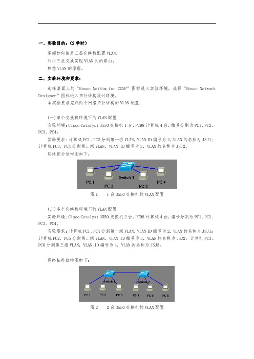
本实验要求完成两个网络拓扑结构的VLAN配置:(一)单个交换机环境下的VLAN配置实验环境:Cisco Catalyst 3550交换机1台,PC98计算机4台,编号分别为PC1、PC2、PC3、PC4。
实验要求:计算机PC1、PC2分到第一组VLAN,VLAN ID编号为2,VLAN的名称为JSJ1;计算机PC3、PC4分到第二组VLAN,VLAN ID编号为3,VLAN的名称为JSJ2。
网络拓扑结构图如下:图1 1台3550交换机的VLAN配置(二)多个交换机环境下的VLAN配置实验环境:Cisco Catalyst 3550交换机2台,PC98计算机4台,编号分别为PC1、PC2、PC3、PC4。
实验要求:计算机PC1、PC4分到第一组VLAN,VLAN ID编号为2,VLAN的名称为JSJ1;计算机PC2、PC5分到第二组VLAN,VLAN ID编号为3,VLAN的名称为JSJ2; 计算机PC3、PC6分到第三组VLAN,VLAN ID编号为4,VLAN的名称为JSJ3。
网络拓扑结构图如下:图2 2台3550交换机的VLAN配置三、实验内容和步骤:(一)单个交换机环境下的VLAN配置第一步:进入实验环境,按照实验要求,在Boson Network Designer中完成网络拓扑结构的设计。
注意:3550交换机Switch1的Fast Ethernet 0/1端口和PC1的Ethernet 0端口连接,Fast Ethernet 0/2端口和PC2的Ethernet 0端口连接,Fast Ethernet 0/3端口和PC3的Ethernet 0端口连接,Fast Ethernet 0/4端口和PC4的Ethernet 0端口连接。
三层交换VLAN路由配置技巧详解
三层交换VLAN路由配置技巧详解三层交换VLAN路由配置技巧详解在华为三层交换机上创建VLAN,端口划分,三层VLAN接口地址配置,静态路由或是RIP协议配置。
跟店铺来学习一下配置过程。
静态路由配置过程:PCA:ip address:10.1.1.2/24 gw:10.1.1.1/24(VLAN2路由接口IP 地址)PCB:ip address:10.1.2.2/24 gw:10.1.2.1/24(VLAN3路由接口IP 地址)PCC:ip address:10.1.3.2/24 gw:10.1.3.1/24(VLAN2路由接口IP 地址)S3526A和S352B之间的`互联网段为10.1.4.0、24分配S3526A VLAN4路由接口IP地址为10.1.4.1/24,S3526B VLAN4路由接口IP地址为10.1.4.2/24三层交换机配置创建VLAN,把PC划到特定VLAN中://创建VLAN[S3526A]vlan 2//把端口划到VLAN中[S3526A-VLAN 2]port ethernet0/9 to ethernet0/12[S3526A-VLAN 2]vlan 3[S3526A-VLAN 2]port ethernet0/13 to ethernet0/16[S3526A-VLAN 2]vlan 4//交换机B的配置:[S3526B]vlan 2[S3526B-VLAN 2]port ethernet0/9 to ethernet0/12[S3526B-VLAN 2]vlan 4配置各台PC的网关地址和交换机之间的网段地址://进入VLAN接口配置模式:[S3526A]interface Vlan-interface 2//配置三层VLAN路由接口地址[S3526A-Vlan-interface2]ip address 10.1.1.1 255.255.255.0 [S3526A-Vlan-interface2] interface Vlan-interface 3[S3526A-Vlan-interface3]ip address 10.1.2.1 255.255.255.0 [S3526A-Vlan-interface3] interface Vlan-interface 4[S3526A-Vlan-interface4]ip address 10.1.4.1 255.255.255.0 [S3526B]interface Vlan-interface 2[S3526B-Vlan-interface2]ip address 10.1.3.1 255.255.255.0 [S3526B-Vlan-interface2] interface Vlan-interface 4[S3526B-Vlan-interface4]ip address 10.1.4.2 255.255.255.0 在二台三层交换机上配置非直连网段静态路由:[S3526A]ip route-static 10.1.3.0 255.255.255.0 10.1.4.2 [S3526B]ip route-static 10.1.1.0 255.255.255.0 10.1.4.1 [S3526B]ip route-static 10.1.2.0 255.255.255.0 10.1.4.1查看路由表,查看网络互通情况:[S3526B]display ip routing-tableRouting Table: public netDestination/Mask Proto Pre Cost Nexthop Interface10.1.1.0/24 STATIC 60 0 10.1.4.1 Vlan-interface410.1.2.0/24 STATIC 60 0 10.1.4.1 Vlan-interface410.1.3.0/24 DIRECT 0 0 10.1.3.1 Vlan-interface210.1.3.1/32 DIREC T 0 0 127.0.0.1 InLoopBack010.1.4.0/24 DIRECT 0 0 10.1.4.2 Vlan-interface40.1.4.2/32 DIRECT 0 0 127.0.0.1 InLoopBack0127.0.0.0/8 DIRECT 0 0 127.0.0.1 InLoopBack0127.0.0.1/32 DIRECT 0 0 127.0.0.1 InLoopBack0RlP协议在三层交换机上的配置1.继续上面的,删除前面配置的静态路由。
三层交换机实现VLAN间通信

三层交换机实现VLAN间通信现代企业网络中,为了有效管理网络资源和提高网络安全性,常常会对网络进行VLAN 划分。
VLAN(Virtual Local Area Network)是一种逻辑上的局域网络,通过VLAN可以将不同物理位置上的设备组成一个逻辑上的局域网络,从而实现更好的管理和安全控制。
而在实际的网络中,为了不同VLAN间的通信,需要借助三层交换机来实现VLAN间通信。
本文将详细介绍三层交换机实现VLAN间通信的原理和方法。
一、三层交换机的作用在传统的网络中,二层交换机主要负责交换数据帧,根据目标MAC地址将数据帧转发到正确的端口,但它并不理解IP地址和路由信息。
而三层交换机则结合了交换机和路由器的功能,不仅能够根据MAC地址进行转发,还能够根据IP地址和路由表实现数据包的转发和路由选择。
三层交换机在实现VLAN间通信时起到了至关重要的作用。
在VLAN划分的网络中,不同的VLAN被视为不同的逻辑网络,它们之间默认是无法直接通信的。
三层交换机的作用就是要实现不同VLAN之间的通信,它可以基于VLAN和IP地址实现不同VLAN之间的数据包转发。
具体原理如下:1. VLAN划分:需要在三层交换机上进行VLAN的配置,将不同的端口划分到不同的VLAN中,这样可以确保不同VLAN中的设备被隔离开。
2. 路由表配置:接下来,需要在三层交换机上配置路由表,将不同VLAN的IP子网和相应的接口关联起来,这样可以使得三层交换机能够理解不同VLAN之间的路由信息。
3. 跨VLAN通信:通过配置交换机的接口,使得不同VLAN上的设备可以通过三层交换机进行通信。
在数据包进入三层交换机的端口时,根据路由表上的信息,可以将数据包转发到正确的VLAN,并最终实现不同VLAN间的通信。
接下来,我们将详细介绍如何在三层交换机上进行VLAN间通信的配置。
以下以思科公司的三层交换机为例进行说明。
1. 配置VLAN#进入交换机全局模式Switch>enableSwitch#conf t#创建VLAN 10Switch(config)#vlan 10Switch(config-vlan)#name VLAN10Switch(config-vlan)#exit#创建VLAN 20Switch(config)#vlan 20Switch(config-vlan)#name VLAN20Switch(config-vlan)#exit#配置端口划分到不同的VLANSwitch(config)#interface fastethernet 0/1Switch(config-if)#switchport mode accessSwitch(config-if)#switchport access vlan 10Switch(config-if)#exitSwitch(config)#interface fastethernet 0/2Switch(config-if)#switchport mode accessSwitch(config-if)#switchport access vlan 20Switch(config-if)#exit3. 配置跨VLAN通信Switch(config)#interface fastethernet 0/3Switch(config-if)#switchport mode trunkSwitch(config-if)#switchport trunk allowed vlan 10,20Switch(config-if)#exit四、总结通过三层交换机的VLAN间通信配置,可以实现不同VLAN之间的数据包转发和通信,使得不同VLAN中的设备能够相互访问和通信,同时又能够保持彼此的隔离。
不同vlan间通信-简单三层交换机配置
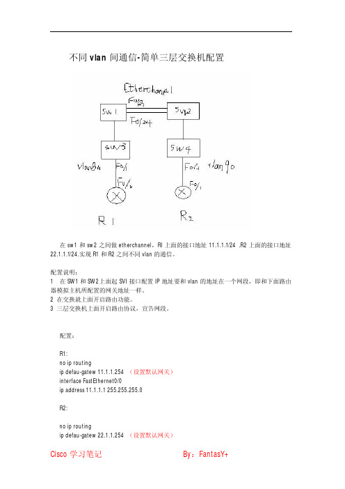
不同vlan间通信-简单三层交换机配置在sw1和sw2之间做etherchannel,RI上面的接口地址11.1.1.1/24.R2上面的接口地址22.1.1.1/24.实现R1和R2之间不同vlan的通信。
配置说明:1在SW1和SW2上面起SVI接口配置IP地址要和vlan的地址在一个网段,即和下面路由器模拟主机所配置的网关地址一样。
2在交换就上面开启路由功能。
3三层交换机上面开启路由协议,宣告网段。
配置:R1:no ip routingip defau-gatew11.1.1.254(设置默认网关)interface FastEthernet0/0ip address11.1.1.1255.255.255.0R2:no ip routingip defau-gatew22.1.1.254(设置默认网关)interface FastEthernet0/0ip address22.1.1.1255.255.255.0SW1:ip routinginterface Port-channel1(做etherchannel)no switchport(关闭交换)ip address12.1.1.1255.255.255.0(设置IP地址)interface FastEthernet0/23no switchport(物理接口关闭交换功能)no ip addresschannel-group1mode auto9(etherchan1模式为auto)interface FastEthernet0/24no switchportno ip addresschannel-group1mode autointerface Vlan80(给svi接口配置IP地址为默认网关地址)ip address11.1.1.254255.255.255.0router ospf1(起路由协议)router-id1.1.1.1network11.1.1.00.0.0.255area0network12.1.1.00.0.0.255area0SW2:ip routinginterface Port-channel1no switchportip address12.1.1.2255.255.255.0interface FastEthernet0/23no switchportno ip addresschannel-group1mode autointerface FastEthernet0/24no switchportno ip addresschannel-group1mode autointerface Vlan90ip address22.1.1.254255.255.255.0 router ospf1router-id2.2.2.2network12.1.1.00.0.0.255area0 network22.1.1.00.0.0.255area0 SW3:interface FastEthernet0/1 switchport access vlan80 switchport mode accessSW4:interface FastEthernet0/2 switchport access vlan90 switchport mode access。
实验二:三层交换机基本配置及VLAN通信

在交换网络中,通过Vlan对一个物理网络进行了逻辑划分,不同的 在交换网络中,通过 对一个物理网络进行了逻辑划分, 对一个物理网络进行了逻辑划分 Vlan之间是无法直接访问的,必须通过三层的路由设备进行连接。 之间是无法直接访问的, 之间是无法直接访问的 必须通过三层的路由设备进行连接。 一般利用路由器或三层交换机来实现不同Vlan之间的互相访问。三 之间的互相访问。 一般利用路由器或三层交换机来实现不同 之间的互相访问 层交换机和路由器具备网络层的功能,能根据数据的IP包头信息 包头信息, 层交换机和路由器具备网络层的功能,能根据数据的 包头信息, 进行选路和转发,从而实现不同网段之间的访问。 进行选路和转发,从而实现不同网段之间的访问。 直连路由是指:为三层设备的接口配置 地址 并激活该端口, 地址, 直连路由是指:为三层设备的接口配置IP地址,并激活该端口,三 层设备会自动产生该接口IP所在网段的直连路由信息 所在网段的直连路由信息。 层设备会自动产生该接口 所在网段的直连路由信息。 三层交换机实现Vlan互访的原理是,利用三层交换机的路由功能, 互访的原理是,利用三层交换机的路由功能, 三层交换机实现 互访的原理是 通过识别数据包的IP地址,查找路由表进行选路转发。三层交换机 通过识别数据包的 地址,查找路由表进行选路转发。 地址 利用直连路由可以实现不同Vlan之间的互相访问。三层交换机给接 之间的互相访问。 利用直连路由可以实现不同 之间的互相访问 口配置IP地址 采用SVI(交换虚拟接口)的方式实现 地址, 间互连。 口配置 地址,采用 (交换虚拟接口)的方式实现Vlan间互连。 间互连 SVI是指为交换机中的 是指为交换机中的Vlan创建虚拟接口,并且配置 地址。 创建虚拟接口, 地址。 是指为交换机中的 创建虚拟接口 并且配置IP地址
VLAN与三层交换机的原理与配置,你懂了吗?
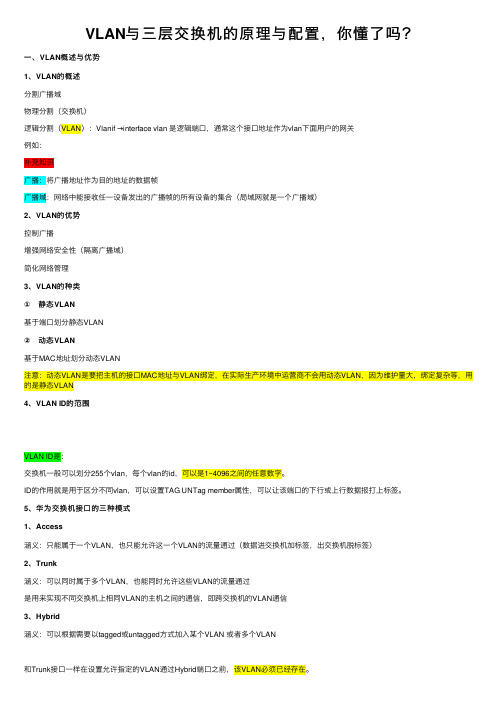
VLAN与三层交换机的原理与配置,你懂了吗?⼀、VLAN概述与优势1、VLAN的概述分割⼴播域物理分割(交换机)逻辑分割(VLAN):Vlanif →interface vlan 是逻辑端⼝,通常这个接⼝地址作为vlan下⾯⽤户的⽹关例如:补充知识⼴播:将⼴播地址作为⽬的地址的数据帧⼴播域:⽹络中能接收任⼀设备发出的⼴播帧的所有设备的集合(局域⽹就是⼀个⼴播域)2、VLAN的优势控制⼴播增强⽹络安全性(隔离⼴播域)简化⽹络管理3、VLAN的种类① 静态VLAN基于端⼝划分静态VLAN② 动态VLAN基于MAC地址划分动态VLAN注意:动态VLAN是要把主机的接⼝MAC地址与VLAN绑定,在实际⽣产环境中运营商不会⽤动态VLAN,因为维护量⼤,绑定复杂等,⽤的是静态VLAN4、VLAN ID的范围VLAN ID是:交换机⼀般可以划分255个vlan,每个vlan的id,可以是1~4096之间的任意数字。
ID的作⽤就是⽤于区分不同vlan,可以设置TAG UNTag member属性,可以让该端⼝的下⾏或上⾏数据报打上标签。
5、华为交换机接⼝的三种模式1、Access涵义:只能属于⼀个VLAN,也只能允许这⼀个VLAN的流量通过(数据进交换机加标签,出交换机脱标签)2、Trunk涵义:可以同时属于多个VLAN,也能同时允许这些VLAN的流量通过是⽤来实现不同交换机上相同VLAN的主机之间的通信,即跨交换机的VLAN通信3、Hybrid涵义:可以根据需要以tagged或untagged⽅式加⼊某个VLAN 或者多个VLAN和Trunk接⼝⼀样在设置允许指定的VLAN通过Hybrid端⼝之前,该VLAN必须已经存在。
Hybrid端⼝和Trunk端⼝在接收数据时,处理思路⽅法是⼀样的,唯⼀区别之处在于发送数据时,Hybrid端⼝具有解除多VLAN标签的功能,Hybrid端⼝可以允许多个VLAN的报⽂发送时不打标签,从⽽增加了⽹络的灵活性,在⼀定程度上也增加了安全性,⽽Trunk端⼝只允许缺省VLAN的报⽂发送时不打标签。
- 1、下载文档前请自行甄别文档内容的完整性,平台不提供额外的编辑、内容补充、找答案等附加服务。
- 2、"仅部分预览"的文档,不可在线预览部分如存在完整性等问题,可反馈申请退款(可完整预览的文档不适用该条件!)。
- 3、如文档侵犯您的权益,请联系客服反馈,我们会尽快为您处理(人工客服工作时间:9:00-18:30)。
设置VTP domain(核心、分支交换机都设置)Switch>enSwitch#config tSwitch(config)#hostname switch-hxswitch-hx(config)#exitswitch-hx#vlan dataswitch-hx(vlan)#vtp domain comswitch-hx(vlan)#vtp serverswitch-hx(vlan)# exitswitch-hx#copy run startSwitch>enSwitch#config tSwitch(config)#hostname switch-fz1switch-fz1(config)#exitswitch-fz1#vlan dataswitch-fz1(vlan)#vtp domain comswitch-fz1(vlan)#vtp clientswitch-fz1(vlan)#exitswitch-fz1#copy run startSwitch>enSwitch#config tSwitch(config)#hostname switch-fz2switch-fz2(config)#exitswitch-fz2#vlan dataswitch-fz2(vlan)#vtp domain comswitch-fz2(vlan)#vtp clientswitch-fz2(vlan)#exitswitch-fz2#copy run startSwitch>enSwitch#config tSwitch(config)#hostname switch-fz2switch-fz4(config)#exitswitch-fz4#vlan dataswitch-fz4(vlan)#vtp domain comswitch-fz4(vlan)#vtp clientswitch-fz4(vlan)#exitswitch-fz4#copy run startSwitch>enSwitch#config tSwitch(config)#hostname switch-fz5Switch-fz5(config)#exitSwitch-fz5#vlan dataSwitch-fz5(vlan)#vtp domain comSwitch-fz5(vlan)#vtp clientSwitch-fz5(vlan)#exitSwitch-fz5#copy run start将端口设置为trunk端口switch-hx>enswitch-hx#config tswitch-hx(config)#int g0/1switch-hx(config-if)#switchport mode trunk switch-hx(config-if)#exitswitch-hx(config)#int g0/2switch-hx(config-if)#switchport mode trunk switch-hx(config-if)#exitswitch-hx#copy run startswitch-fz1>enswitch-fz1#config tswitch-fz1(config)#int g1/1switch-fz1(config-if)#switchport mode trunk switch-fz1(config-if)#exitswitch-fz1(config)#int f0/1switch-fz1(config-if)#switchport mode trunk switch-fz1(config-if)#exitswitch-fz1(config)#int f0/2switch-fz1(config-if)#switchport mode trunk switch-fz1(config-if)#endswitch-fz1#copy run startswitch-fz2>enswitch-fz2#config tswitch-fz2(config)#int f0/1switch-fz2(config-if)#switchport mode trunk switch-fz2(config-if)#endswitch-fz2#copy run startswitch-fz3>enswitch-fz3#config tswitch-fz3(config)#int f0/1switch-fz3(config-if)#switchport mode trunk switch-fz3(config-if)#endswitch-fz3#copy run startswitch-fz3#switch-fz4>enswitch-fz4#config tswitch-fz4(config)#int g1/1switch-fz4(config-if)#switchport mode trunk switch-fz4(config-if)#exitswitch-fz4(config)#int f0/1switch-fz4(config-if)#switch mode trunk switch-fz4(config-if)#endswitch-fz4#copy run startswitch-fz4#switch-fz5>enswitch-fz5#config tswitch-fz5(config)#int f0/1switch-fz5(config-if)#switchport mode trunk switch-fz5(config-if)#endswitch-fz5#copy run startswitch-fz5#在核心交换机上建立VLANswitch-hx(vlan)#vlan 10 name aaaVLAN 10 added:Name: aaaswitch-hx(vlan)#vlan 11 name bbbVLAN 11 added:Name: bbbswitch-hx(vlan)#将交换机端口划入VLANswitch-fz1>enswitch-fz1#config tswitch-fz1(config)#int f0/3switch-fz1(config-if)#switchport access vlan 10 switch-fz1(config-if)#exitswitch-fz1(config)#int f0/4switch-fz1(config-if)#switchport access vlan 11 switch-fz1(config-if)#endswitch-fz1#copy run startswitch-fz2>enswitch-fz2#config tswitch-fz2(config)#int f0/3switch-fz2(config-if)#switchport access vlan 10 switch-fz2(config-if)#exitswitch-fz2(config)#int f0/4switch-fz2(config-if)#switchport access vlan 11 switch-fz2(config-if)#endswitch-fz2#copy run startswitch-fz2#switch-fz3>enswitch-fz3#config tswitch-fz3(config)#int f0/3switch-fz3(config-if)#switchport access vlan 10 switch-fz3(config-if)#exitswitch-fz3(config)#int f0/4switch-fz3(config-if)#switchport access vlan 11 switch-fz3(config-if)#endswitch-fz3#copy run startswitch-fz3#switch-fz4>enswitch-fz4#config tswitch-fz4(config)#int f0/3switch-fz4(config-if)#switchport access vlan 10switch-fz4(config-if)#exitswitch-fz4(config)#int f0/4switch-fz4(config-if)#switchport access vlan 11switch-fz4(config-if)#endswitch-fz4#copy run starswitch-fz5>enswitch-fz5#config tswitch-fz5(config)#int f0/3switch-fz5(config-if)#switchport access vlan 10switch-fz5(config-if)#exitswitch-fz5(config)#int f0/4switch-fz5(config-if)#switchport access vlan 11switch-fz5(config-if)#endswitch-fz5#copy run startswitch-fz5#配置三层交换switch-hx>enswitch-hx#config tswitch-hx(config)#int vlan 10upswitch-hx(config-if)#ip add 192.168.91.254 255.255.255.0switch-hx(config-if)#exitswitch-hx(config)#int vlan 11switch-hx(config-if)#ip add 192.168.92.254 255.255.255.0switch-hx(config-if)#三层交换机默认已启动路由,ip routing命令可暂时不用,如路由被关掉,可用此命令。