FLUENT12流固耦合精选教程
fluent 流固耦合
fluent 流固耦合介绍在物理学和工程领域中,流固耦合是指涉及流体与固体之间相互作用的问题。
流固耦合分析是一种综合考虑固体机械结构和流体力学行为的方法。
通过对流体和固体之间的相互作用进行建模和分析,可以更准确地预测各种物理过程和现象的发生和演化。
本文将深入探讨流固耦合的相关概念、方法和应用。
流固耦合的基础理论流体力学基础1.流体的性质–流体的连续性假设–流体的黏性与非黏性–流体的压缩性与非压缩性2.流体力学方程–质量守恒方程–动量守恒方程–能量守恒方程3.流体的边界条件–定义速度边界条件–定义压力边界条件–定义温度边界条件固体力学基础1.固体的性质–固体的应力和应变–固体的弹性与塑性–固体的线性与非线性2.固体力学方程–应力-应变关系–力学平衡方程–边界条件的定义3.固体材料的本构关系–线性弹性本构关系–线性塑性本构关系–非线性本构关系流固耦合的数值模拟方法1.有限差分法2.有限元方法3.边界元方法4.网格方法5.颗粒法流固耦合的应用领域汽车工程1.车辆风阻与空气动力学特性2.燃料注射与燃烧过程3.轮胎与路面的相互作用4.车身结构的振动与噪音特性航空航天工程1.飞行器的气动力学性能2.发动机与燃气轮机的热力学分析3.空气动力装置的设计与优化4.相空间推进器的工作原理与优化能源与环境工程1.燃烧过程与排放特性分析2.石油、天然气与水力能源的开发3.太阳能与风能的利用与储存4.水动力与水文模型的建立与分析生物医学工程1.血流动力学与心脏瓣膜病的研究2.器官移植与人工假肢的设计3.细胞生长与组织工程的模拟与优化4.医用材料与医疗器械的性能测试与分析结论通过对流体力学和固体力学的相互作用进行建模和模拟,流固耦合分析能够更准确地预测各种物理过程和现象的发生和演化。
在不同的工程领域中,流固耦合分析都具有重要的应用价值。
通过不断改进和创新流固耦合分析的方法和技术,可以进一步推动工程领域的发展和进步。
流固耦合分析作为一种综合应用的方法,在未来的研究和实践中,将继续发挥重要的作用。
fluent流--固耦合传热-图文
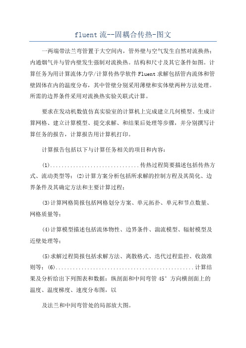
fluent流--固耦合传热-图文一两端带法兰弯管置于大空间内,管外壁与空气发生自然对流换热;内通烟气并与管内壁发生强制对流换热。
结构和尺寸及其它条件如图。
计算任务为用计算流体力学/计算传热学软件Fluent求解包括管内流体和管壁固体在内的温度分布,其中管壁分别采用薄壁和实体壁两种方法处理。
所需的边界条件采用对流换热实验关联式计算。
要求在发动机数值仿真实验室的计算机上完成建立几何模型、生成计算网格、建立计算模型、提交求解、和结果后处理等步骤,并分别撰写计算任务的报告,计算报告用计算机打印。
计算报告包括以下与计算任务相关的项目和内容:(1)...............................传热过程简要描述包括传热方式、流动类型等;(2)计算方案分析包括所求解的控制方程及其简化、边界条件及其确定方法和主要计算过程;(3)计算网格简报包括网格划分方案、单元拓扑、单元和节点数量、网格质量等;(4)计算模型描述包括流体物性、边界条件、湍流模型、辐射模型及近壁处理等;(5)求解过程简报包括求解方法、离散格式、迭代过程监控、收敛准则等;(6)................................................计算结果及分析给出下列图表和数据:纵剖面和中间弯管45°方向横剖面上的温度、温度梯度、速度分布图,以及法兰和中间弯管处的局部放大图。
管内壁面上的温度、热流密度和表面传热系数分布,包括三维分布和沿管长度方向上的分布。
............................................................ .........................................总热流量。
由2种数值计算方法求得管内外烟气和空气之间换热的平均传热系数和烟气出口温度,并与工程算法得到的数值对比。
1、传热过程简述计算任务为用计算流体力学/计算传热学软件Fluent求解通有烟气的法兰弯管包括管内流体和管壁固体在内的温度分布,其中管壁分别采用薄壁和实体壁两种方法处理。
ANSYSWorkbenchFluent流固耦合传热及热结构分析学习教案
会计学
1
第一页,共7页。
以前本人发了一个贴子,关于Fluent 计算的 温度如 何传递 到结构 网格上 ,该方 法已经 过时, 由于AN SYS Workbench功能的日益强大,建议 使用更 好、更 简便的 方法。 案例(àn lì)如下: 1 打开Workbench,tool box/component systems里选mesh,空白区出现如下图,然后双击Geometry,导入几何模型,这是一个外部固体包裹内部管流的简单(jiǎndān)模型,仅用于演示步骤。任选一个Part, 在Details of Body里有个选项Fluid/Solid,需要分别定义好流体和固体
第5页/共7页ቤተ መጻሕፍቲ ባይዱ
第六页,共7页。
6 添加约束,计算。 这仅是个简单演示,具体(jùtǐ)问题还 要涉及 到定义 材料塑 性应力 应变数 据,分 析的非 线性设 置,接 触的设 置等等 。
第6页/共7页
第七页,共7页。
Named selections命令分别创建 Inlet, outlet和wallout. Wallout用来定
义固体外表面与环境的对流换热边界条件
第2页/共7页
第三页,共7页。
3 关闭Meshing 窗口返回到project schematic界面,右击Mesh→Transfer Data To New → Fluent, 将建立Fluent的分析项目。 此时Mesh后面变为闪电(shǎndiàn)符号,需右击它再点菜单中update
双击Setup,打开Fluent窗口,设置材 料(cáili ào)、流 相固相 、激活 能量方 程、湍 流模型 、边界 条件等 。进口 流速1m/s, 600K, 出口0pa,wallout定义对流换热系 数5, 环境温 度300K。
fluent流固耦合设定
fluent流固耦合设定一、什么是流固耦合设定?流固耦合是指流体和固体之间相互作用的过程。
在工程领域中,很多问题涉及到流体与固体的相互作用,例如水下管道的抗风荷载、风力发电机的叶片动力响应等。
在这些问题中,不能简单地将流体和固体分离开来考虑,而是需要将它们作为一个整体进行计算。
因此,流固耦合设定就是在计算流体和固体相互作用问题时,将它们进行耦合设定,使它们之间的相互作用能够得到准确的计算和分析。
流固耦合设定是一种数值模拟方法,通过对流体和固体的运动方程和力学方程进行求解,来模拟流体和固体在相互作用过程中的行为。
在流固耦合设定中,流体和固体之间存在力的作用,当流体流过固体时,会对固体施加压力,而固体对流体也会产生阻力。
通过将流体和固体的运动方程相互耦合,可以模拟流体流经固体体积或表面时产生的力和位移。
流固耦合设定可以用于研究湍流、热传导、质量传输等问题,广泛应用于航空航天、水利水电、化工等领域。
二、流固耦合设定的应用领域1. 航空航天工程在航空航天工程中,流固耦合设定被广泛应用于飞行器的气动弹性研究。
在设计飞行器时,需要考虑飞行器的结构是否能够在气动载荷下安全运行。
通过流固耦合设定,可以模拟飞行器在不同空速下的气动载荷,并研究飞行器结构在不同载荷作用下的动力响应。
这有助于优化飞行器的结构设计,提高飞行器的飞行性能和安全性。
2. 水利水电工程在水利水电工程中,流固耦合设定被用于模拟水下建筑物的抗风荷载。
水下建筑物如海底管道、海底电缆等在受到风、流的作用时,会产生振动和应力,可能导致结构破坏。
通过流固耦合设定,可以模拟水下建筑物在风、流作用下的动态响应,为水下工程的设计和施工提供可靠的依据。
3. 化工工程在化工工程中,流固耦合设定被用于模拟颗粒流体化的过程。
例如在粉煤灰输送管道中,颗粒和气体同时存在的情况下,可以使用流固耦合设定来模拟颗粒的运动轨迹和流体的流动状态。
这对于优化输送管道的设计和操作参数的选择非常有帮助。
(完整版)利用FLUENT软件模拟流固耦合散热实例
Symmetry Planes
Air Outlet
Electronic Chip (one half is modeled) k = 1.0 W/m∙K Q = 2 Watts
Circuit board (externally cooled) k = 0.1 W/m∙K h = 1.5 W/m2∙K T∞ = 298 K
在Scale Grid菜单中,选择Grid was created in inch, 点击 change length units, 然后再点击 Scale, 得到正确 大小的计算区域。
3 . 选择求解器,物理模型 ① Define—Model--Solver
② Define—Model--Energy
7.用体相分割,得到流体区域Volume 2
Volume 2 split with volume 3
Volume 2
Volume 3
划分网格
1.将chip边划分为15*7*4
7 4
15
2.划分其他边的网格
8 16 16
44
100 100
8
16
16 4
划分数:
Board沿Y向边: 4 Board沿Z向边: 8 Fluid 沿Y向边: 16 沿X方向长边: 100
⒊
在Solid面板中,勾选Source Terms,然后选择Source Terms菜单,点击Edit,进入Energy面板,将数值设为1, 菜单将扩展开来,从下拉选项中选择constant, 然后将前面数值设定为904000,然后确认OK。
④ 指定速度入口条件
在Boundary Conditions面板中,Zone下面选择inlet, 确认Type下为velocity-inlet,点击Set进入到Velocityinlet面板中,在velocity specification method右边选 择Magnitude and Direction, 菜单展宽。 在Velocity Magnitude后面输入1, 在x-Componen of Flow Direction后面输入1,其他方向保持为0。表 示air流体沿x方向以1m/s的大小流动。 选择Thermal 菜单将Temperature设定为298K。
FLUENT12流固耦合精选教程

Training Manual
• Right-click on “Mesh” and select Insert-->Inflation • Click on “Flow” body in graphics window and click Apply button beside “Geometry” under “Details of Inflation”
ANSYS, Inc. Proprietary © 2009 ANSYS, Inc. All rights reserved.
1-5
April 30, 2009
WORKSHOP 1
Manual Setup on Project Page
Training Manual
• In a similar fashion, left click in the Solution Cell (A5) of “Fluid Flow (FLUENT)”system and drag it into the Setup Cell of the “Static Structural (ANSYS)” system. Transfer A5 indicates that the solution data from “A5” will be transferred to cell “B3”. The solution data will be used as a pressure load in “Static Structural (ANSYS) system.
– Double-click to create system schematic shown below
ANSYS, Inc. Proprietary © 2009 ANSYS, Inc. All rights reserved.
流固耦合过程_教程
流固耦合过程_教程
一、流体固耦合过程
流体固耦合过程指的是通过流体与固体材料的耦合,从而解决固体力学、热力学、电磁学等问题,从而改善系统性能的一种计算方法。
这种方
法是由一组不同类型的有限元控制方法组成的,可以用来描述流体流动的
流动领域,并以一组相应的弹性、热力学和电磁场域来描述固体的变形和
力学性能。
当然,最重要的是,这种方法还能够充分考虑流体与固体间的
耦合作用,从而决定系统性能。
1.有限元技术
有限元技术是流体固耦合方法的核心,它是分析复杂系统的重要技术,主要应用于建模、仿真和优化设计等领域。
具体来说,有限元技术是指将
一个复杂力学系统分割成几个若千个力学单元,分析每个单元内的变形状态,从而确定系统的总体变形状态。
有限元技术一方面可以有效描述一个
力学系统的总体变形状态,另一方面也可以计算出具体力学单元内的变形
状态。
2.耦合分析
耦合分析是流体固耦合方法中的重要组成部分,主要是指将流体和固
体的分析结果进行耦合,以表示流体与固体间的耦合关系,包括流体和固
体静力学、热力学和电磁学等方面的耦合关系。
耦合分析可以有效地模拟
流体与固体间的耦合关系,从而改善系统的性能。
(完整版)流固耦合教学
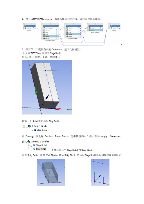
1、打开ANSYS Workbench, 拖动各模块到空白区,并照此连接各模块。
2 2、打开第一个模块当中的Geometry,建立几何模型:(1)在XY Plane内建立Ship Shell船长:0.4、船宽:0.14、型深0.11将第一个Solid重命名为Ship Solid在Concept中选择Surfaces From Faces,选中模型的六个面,然后Apply、Generate。
重命名第二个Ship Solid为Ship Shell右击Ship Solid, 选择Hide Body,显示Ship Shell, 然后对Ship Shell执行同样操作(即隐去)(2)在YZ Plane内建立液舱单击(New Plane),选择YZ plane,,Apply一下将YZ Plane 向X正方(图中为法向,即Z)向偏移0.02mGenerate一下,然后Show body 一下Ship Solid 与Ship Shell可以看到YZ Plane已平移到Body内了再将Ship Solid 与Ship Shell 都Hide,选择Plane 4,调为正视,Generate一下新建一个Sketch:单击,显示,在此Sketch中建立液舱模型草图单击约束(Constrains),将草图中的“水平线”调整为水平,“垂直线”调整为垂直:事实上仅用Horizontal(水平)和Vertical(垂直)就OK了。
以水平约束为例,先单击Horizontal,再依次单击草图中的水平线段。
调整后如下图所示:定义尺寸:左下角空缺的部分是预留贴“应变片”的部分,需要单独建模单击Extrude(拉伸),设置Operation(下拉列表中改选为Add Frozen)与拉伸尺寸(0.1m):然后Generate一下将第三个Solid重命名为Fluid,拉伸后的效果如下:再新建一个Sketch,显示,在空缺处画一个长方形,然后拉伸0.1m,(其中Operation属性同样选为Add Frozen),Generate一下,同样把第四个Solid重命名为Fluid建立舱壁:在Concept中选择Surfaces From Faces,选中除“应变片”外的其余9个面图中“应变片”显示为未着色,即不选中,然后Generate一下将第五个Fluid重命名为Fluid Shell再Surfaces From Faces一次,选中“应变片”,Apply,Generate,同样将其重命名为Fluid Shell选中Fluid(内流场),将其属性改为Fluid,(Fluent中默认均为Solid)选中“内流场”,右击,选择Form New part,并重命名为Fluid再选中舱壁(Fluid Shell)也组成一个part,并重命名为Fluid Shell到此,液舱(内流场与舱壁)就建完了,然后将二者都执行Hide body(3)在ZX Plane内建外流场选择,调整为正视,旋转坐标系先确定外部尺寸,再确定内部尺寸:外部流场关于坐标轴(横轴)对称,两边各距离横轴0.3m,前后距离纵轴距离分别为:0.3m、3.14m. 内部为船体位置,横向(船宽)为0.14m、纵向(型深)为0.11m拉伸(Extrude)一下,拉伸长度为船长,即0.4m ,其中Operation选择Add Frozen,Generate 一下图中显示外流场把船体的位置给空了出来,将重命名为Out Fluid,同时将属性改为Fluid接下来进行流场切分(Slice):在Tools中选择Freeze,产生透明效果单击Slice(或者在Create中单击Slice),在Slice Type中选择Slice by surface,点击Target Face,选中船体所在位置(即图中外流场所空出来的位置)内侧某一个面(以左侧面为第一个面为例),Appy一下。
ANSYS12流固耦合的操作实例
流固耦合FSI分析分析原理:流场采用CFX12,固体采用ANSYS12分别计算,通过界面耦合。
流体网格:流体部分采用HyperMesh9.0分网,按照流体分网步骤即可,没有特殊要求。
网格导出:CFX可以很好的支持Fluent的.cas格式。
直接导出这个格式即可。
流体的其余设置都在CFX-PRE中设置。
固体网格即设置:HyperMesh9.0划分固体网格。
设置边界条件,载荷选项,求解控制,导出.cdb文件。
实例练习:以CFX12实例CFX tutorial 23作为练习。
为节省时间,将计算时间缩短为2s。
网格划分:提取CFX tutorial 23中的实体模型到hm中,分别划分流体,固体网格。
分别导出为fluent的.cas格式和ansys的cdb格式。
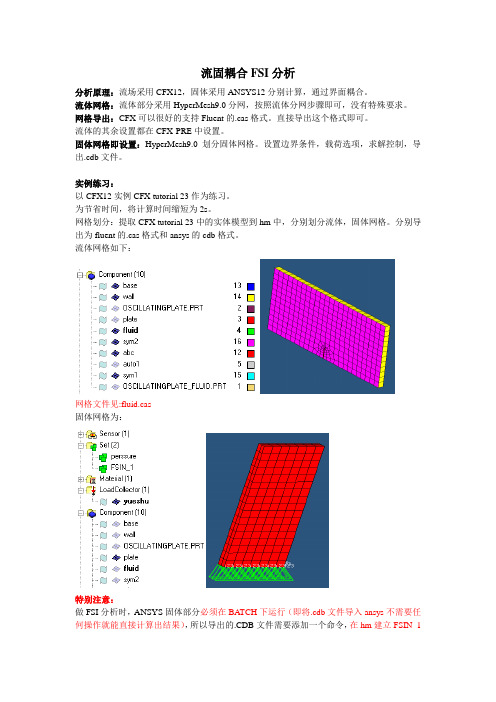
流体网格如下:网格文件见:fluid.cas固体网格为:特别注意:做FSI分析时,ANSYS固体部分必须在BATCH下运行(即将.cdb文件导入ansys不需要任何操作就能直接计算出结果),所以导出的.CDB文件需要添加一个命令,在hm建立FSIN_1的set,以方便在.cdb中手动添加命令SF,FSIN_1,FSIN,1,具体位置在定义了节点集合FSIN_1之后。
另一个set:pressure用于施加压强。
这里还设置了一些控制卡片用于分析,当然也可以直接修改.cdb文件详细.cdb文件请参看plate.cdb将固体部分在ansys中计算一下,以确定没有问题。
通过ansys计算检查最大位移:最上面的点x向变形曲线至此,固体部分的计算文件已经准备好,流体网格需要导入CFX以进一步设置求解选项和耦合选项。
以下在CFX-PRE中进行设置由于固体模型已经生成,故不需要利用workbench,所以不必按照指南的做法。
启动workbench,拖动fluid flow(CFX)到工作区直接双击setup进入CFX-PRE 导入流体网格然后设置分析选项:注意:mechanical input file即是固体部分网格。
【Fluent案例】11:流固耦合[2]
![【Fluent案例】11:流固耦合[2]](https://img.taocdn.com/s3/m/ccf85bcd85254b35eefdc8d376eeaeaad0f31643.png)
【Fluent案例】11:流固耦合[2]上文获取到U型管最大Y方向振动振型所对应的频率为50.4Hz。
本文接上文继续。
1瞬态结构计算设置•Workbench界面中,双击B5单元格进入Transient Structural•右键选择模型树节点Transient,选择弹出菜单Insert → Fixed Support•选择管道进出口两侧最外圈的两个圆边,施加固定约束•右键选择模型树节点Transient,选择弹出菜单Insert →Displacement,属性窗口中,Geometry设置为图中所示选择面•选择Y Component设置框右侧的箭头按钮,选择Function,设置Y Component为0.000025*sin(50.4*360*time)•选择模型树节点Analysis Settings,属性窗口中设置Auto Time Stepping为Off,设置Step End Time为0.1s,设置Time Step为5e-4 s•右键点击模型树节点Transient,选择弹出菜单Insert →Fluid Solid Interface•属性窗口中设置Scoping Method为Named Selection,设置Named Selection为fsi_solid•右键选中模型树节点Solution,选择弹出菜单Insert → Deformation → Directional•属性窗口中,设置Scoping Method为Named Selection,设置Named Selection为Node1,设置Orientation为Y Axis•相同的步骤,插入Node2关闭Transient Structural,返回Workbench。
2稳态Fluent设置先进行稳态Fluent设置,将稳态计算结果作为初始值。
•双击C4单元格,以Double Precision方式启动Fluent•右键选中模型树节点Viscous,选择弹出菜单Model → SST k-omega启用SST k-w湍流模型•右键选择模型树节点Materials > Fluid,选择弹出菜单New…,在材料数据库中添加介质water-liquid,修改其密度Density为1000 kg/m3•右键选择模型树节点Cell Zone Conditions,选择弹出菜单Edit…,弹出计算域设置对话框•在弹出的对话框中设置Material Name为water-liquid•右键选择模型树节点Boundary > inlet,选择右键菜单Edit…,弹出边界条件设置对话框•在对话框中设置velocity Magnitude为20 m/s,设置Specification Method为Intensity and Hydraulic Diameter,设置Turbulent Intensity为1%,设置Hydraulic Diameter为0.02 m•设置outlet边界,如下图所示•双击模型树节点Solution > Method,右侧面板中设置Pressure-Velocity Coupling Scheme为Coupled,激活选项Pseudo Transient及High Order Term Relaxation•右键选择模型树节点Solution > Initialization,选择弹出菜单Initialize进行初始化•鼠标双击模型树节点Solution > Run Calculation,右侧面板中设置Number of Iterations为200,点击按钮Calculate进行计算•关闭Fluent返回Workbench3数据连接•Workbench中,复制Fluent组件,如下图所示•采用如下图所示的数据连接•添加System Coupling模块,并连接B5与D4单元格,如下图所示4瞬态Fluent设置•双击D5单元格进入Fluent•双击模型树节点General,右侧面板中设置Time为Transient•双击模型树节点Dynamic Mesh,右侧面板中激活选项Dynamic Mesh,点击下方按钮Settings…,在弹出的对话框中设置Method为Diffusion,设置Diffusion Parameter为1,点击OK按钮关闭对话框•点击Dynamic Mesh Zones下方的Create/Edit…按钮,在弹出的对话框中选择Zone Name为fsi_fluid,设置其Type为System Coupling,点击Create按钮创建动网格区域•双击模型树节点Run Calculation,右侧面板中设置Number of Time Steps为1,设置Max Iterations/Time Step为5注:这里其实可以随便设,反正Fluent 计算所采用的时间步和时间步长受systemcoupling控制•关闭Fluent,返回至Workbench•右键点击B5单元格,选择菜单Update更新组件5System Coupling设置•双击E2单元格进入System Coupling设置窗口•选中Analysis Settings,下方窗口中设置End Time为0.1 s,设置Step Size为0.0005 s,如下图所示•按住键盘ctrl键同时选择Fluid Solid Interface及fsi_fluid,选择右键菜单项Create Data Transfer•关闭System Coupling设置界面,返回至Workbench界面•右键选择E3单元格,选择菜单项Update进行求解求解时间较长,可能需要等待一两个小时。
fluent流固耦合传热算例
Fluent流固耦合传热算例介绍在工程领域中,流固耦合传热是一个重要的研究领域。
通过数值模拟方法,我们可以对流体和固体之间的传热过程进行分析和优化。
Fluent是一种常用的流体动力学软件,可以用于模拟流体的运动和传热。
本文将介绍一个关于Fluent流固耦合传热的算例,讨论其原理、步骤和结果分析。
算例背景我们以一个热交换器为例来进行流固耦合传热的模拟。
热交换器是一种常见的设备,用于将热量从一个流体传递到另一个流体,常见于工业生产和能源系统中。
通过模拟热交换器的传热过程,我们可以更好地了解其工作原理,优化设计,并提高其传热效率。
模型建立几何模型首先,我们需要建立热交换器的几何模型。
根据具体的热交换器类型和尺寸,我们可以使用CAD软件绘制出几何模型,并导入到Fluent中进行后续的模拟分析。
边界条件在模拟中,我们需要设置合适的边界条件来模拟实际工况。
对于热交换器的模拟,我们通常需要设置流体的入口温度、出口温度、流速等参数,以及固体壁面的温度和热传导系数。
数值模拟流体模拟在进行流固耦合传热模拟之前,我们首先需要进行流体模拟。
通过Fluent软件,我们可以对流体的运动进行数值模拟,并得到流体的速度场、压力场等关键参数。
在热交换器模拟中,我们需要注意流体的流动特性,如湍流、层流等,以及流体的物性参数,如密度、粘度等。
固体传热模拟在得到流体模拟的结果后,我们可以将其作为固体传热模拟的边界条件。
通过设置固体壁面的温度和热传导系数,我们可以模拟固体的传热过程。
在热交换器模拟中,我们通常关注固体的温度分布、热流密度等参数。
流固耦合模拟最后,我们将流体模拟和固体传热模拟结合起来,进行流固耦合传热模拟。
在Fluent中,我们可以通过设置合适的耦合算法和迭代步长,将流体和固体的传热过程耦合起来。
通过迭代计算,我们可以得到流体和固体的传热过程,并分析其传热特性和效率。
结果分析通过流固耦合传热模拟,我们可以得到丰富的结果数据,如流体的速度场、压力场,固体的温度分布、热流密度等。
edem-fluent 耦合流程
edem-fluent 耦合流程edem-FLUENT 耦合流程edem-FLUENT 耦合是一种强大的工具,可用于模拟流固耦合问题,其中流体流动与固体变形相互作用。
该耦合流程涉及以下步骤:模型准备:1. 创建几何模型:在 CAD 软件中创建计算域和流固界面。
2. 网格划分:将计算域和流固界面划分为网格。
网格必须在流固界面上匹配,以确保流体和固体之间的连续性。
edem 设置:1. 导入几何:将网格导入 edem 中。
2. 设置材料属性:为流体和固体指定材料属性,包括密度、杨氏模量和泊松比。
3. 定义边界条件:指定流体入口和出口边界条件、固体位移或载荷边界条件。
FLUENT 设置:1. 导入几何:将网格导入 FLUENT 中。
2. 设置流体模型:选择适当的湍流模型并设置其他流体参数。
3. 定义耦合区域:指定流固界面区域,该区域将进行耦合求解。
4. 设置耦合算法:选择适当的耦合算法,如单向耦合或双向耦合。
耦合求解:1. 耦合初始化:交换初始流体和固体状态,以初始化耦合求解。
2. 求解流体方程:求解流体动量和连续性方程,并将结果传递给 edem。
3. 求解固体方程:求解固体运动方程,并将结果传递给FLUENT。
4. 更新流体和固体状态:更新流体和固体状态,以反映耦合效应。
后处理:1. 可视化结果:可视化流体速度、应力、位移或其他感兴趣的物理量。
2. 提取数据:提取力、扭矩、应力或其他计算结果。
注意事项:网格在流固界面上必须匹配,以确保耦合结果的准确性。
耦合算法的选择取决于特定问题的性质。
求解时间可能很长,具体取决于问题的复杂性和网格大小。
edem-FLUENT 耦合是一项强大的工具,但需要仔细的模型准备和设置才能获得准确的结果。
fluent流固耦合传热udf
fluent流固耦合传热udf
Fluent流固耦合传热UDF(User-Defined Function)是一种用户自定义的函数,在Fluent软件中用于处理流体与固体之间的热传导问题。
通过编写UDF,用户可以根据自己的需求定义不同的热传导模型,而不仅限于Fluent软件中已有的模型。
要编写一个流固耦合传热UDF,用户需要了解Fluent软件中的UDF接口,并熟悉所需的传热模型的数学表达式。
UDF可以用C语言编写,通常使用Fluent 提供的API函数来访问Fluent的求解器和数据。
在编写UDF时,用户需要定义一个主函数,该函数会被Fluent软件调用,并根据需要在循环迭代过程中进行热传导计算。
主要的步骤包括:
1. 导入所需的头文件,包括Fluent的UDF头文件。
2. 定义主函数,命名为DEFINE_ADJUST,在该函数中进行流固耦合传热计算。
3. 在主函数中,使用Fluent提供的API函数获取所需的流场和固体场数据。
4. 根据热传导模型的数学表达式,在主函数中进行热传导计算,并更新流场和固体场的温度分布。
5. 使用Fluent提供的API函数将更新后的温度分布传递给Fluent求解器。
6. 编译UDF,并将其加载到Fluent软件中。
通过使用Fluent流固耦合传热UDF,用户可以更加灵活地定义热传导模型,并
精确地模拟流体与固体之间的热传导过程,从而提高模拟的准确性和实用性。
fluent算流固耦合时的流程
一、概述流固耦合是指流体与固体相互作用的现象,其在工程领域中具有广泛的应用。
在进行流固耦合仿真时,需要考虑流场对固体的影响以及固体对流场的影响,因此需要采用一种特殊的算法——fluent算法。
本文将对fluent算流固耦合时的流程进行详细介绍。
二、建模1. 确定工程问题:首先需要明确工程问题的背景和要解决的目标,例如流体在某一固体表面的作用力、固体对流体的阻力等。
2. 设计流固耦合模型:根据实际情况,设计流固耦合模型,确定流体和固体的边界条件、初始条件和材料参数。
三、流体求解1. 网格划分:将流场的求解区域进行网格划分,确保网格密度足够细致。
2. 设置边界条件:根据流场的实际情况,设置入口边界条件、出口边界条件以及固体表面的边界条件。
3. 求解流场:利用fluent算法对流场进行求解,得到流场的速度、压力等参数分布。
四、固体求解1. 读入流场结果:将流体求解得到的流场参数导入固体模型中。
2. 求解固体模型:根据流场的参数,使用固体力学方程对固体的应力、变形等进行求解。
五、流固耦合求解1. 交互迭代:在流体求解和固体求解的基础上,进行流固耦合交互迭代,通过不断更新流固界面的信息,使得流场和固体的状态逐渐趋于稳定。
2. 收敛判据:设置流固耦合求解的收敛判据,当流场和固体受力达到平衡时停止求解。
六、后处理1. 结果分析:对流固耦合求解得到的结果进行分析,分析流场对固体的影响以及固体对流场的影响。
2. 结果可视化:使用fluent算法中的后处理工具对结果进行可视化处理,生成流固耦合的动态图像和静态图表。
3. 结果验证:与实验结果进行对比验证,提高流固耦合仿真的准确性和可靠性。
七、总结fluent算法在流固耦合仿真中具有较高的精度和可靠性,通过以上的流程与步骤,可以对流固耦合问题进行有效的求解和分析。
在工程领域中,流固耦合仿真的应用将会越来越广泛,为工程设计与优化提供重要的参考依据。
八、实例分析为了更好地理解fluent算法在流固耦合仿真中的流程与步骤,我们可以通过一个实例来进行深入分析。
ansys fluent 流固耦合 应力
ANSYS Fluent 流固耦合应力简介流固耦合是指流体和固体之间相互作用的一种物理现象。
ANSYS Fluent是一种流体动力学模拟软件,可以用于模拟流体流动、传热和化学反应等各种现象。
在流体和固体之间存在相互作用时,应力是一个重要的参数,它描述了固体的变形情况。
本文将介绍如何使用ANSYS Fluent进行流固耦合模拟,并分析模拟结果中的应力分布。
流固耦合模拟步骤步骤一:几何建模在进行流固耦合模拟之前,首先需要进行几何建模。
可以使用ANSYS DesignModeler等软件来创建几何模型,或者导入现有的CAD文件。
几何模型应包括流体区域和固体区域,以及它们之间的接触面。
步骤二:网格划分完成几何建模后,需要对模型进行网格划分。
ANSYS Fluent支持多种网格划分算法,包括结构化网格和非结构化网格。
网格划分的质量对模拟结果有重要影响,因此需要根据具体情况进行合理的网格划分。
步骤三:物理模型设置在进行流固耦合模拟之前,还需要设置物理模型。
首先需要选择合适的流体模型,包括流体类型、流体性质等。
然后需要设置固体模型,包括材料属性、边界条件等。
最后还需要设置相互作用模型,以描述流体和固体之间的相互作用。
步骤四:求解器设置完成物理模型设置后,需要设置求解器。
ANSYS Fluent提供了多种求解器选项,可以根据具体情况选择合适的求解器。
求解器设置包括网格划分、计算时间、收敛准则等。
步骤五:模拟运行完成求解器设置后,可以开始进行模拟运行。
ANSYS Fluent将根据设置的物理模型和求解器进行求解,得到流体和固体的相应结果。
步骤六:应力分析模拟运行完成后,可以对结果进行应力分析。
ANSYS Fluent提供了丰富的后处理工具,可以用于分析模拟结果中的应力分布。
可以通过选取感兴趣的区域或者路径,获取相应的应力数据。
应力分析结果二级标题1:流体区域应力分布在流固耦合模拟中,流体区域的应力分布是一个重要的参数。
Fluent 流固耦合基础教程
2. 流固耦合问题的数值模拟 既然是数值模拟,则需将系统方程在时域上离散。在每个时间步上分别解算流体域和固体域。 固体的变形或位移导致流固边界的运动。这个运动以动网格的形势传递给流场,然后求解流 场。流场的解则包括了这个运动所导致的反力。将这个反力反馈给固体,求解其下一时间步 的响应。如图 1 所示。
3
图4
图5 流体为不可压缩流体,求解器采用一次隐式瞬态算法。LES 的动网格计算上 Fluent 不支持二
4
次格式,这就需要时间步设定要小一些。时间步长和求解器参数的选取也是个复杂的问题, 这里也不展开讨论了。在这个算例中,我们取较大的步长,以加快计算速度。具体参数如下: Time step size: 0.0005 s Solver settings: unsteady / pressure-based / 1st order implicit Viscous model: LES / Smagorinsky-Lilly / no dynamic stress Solution settings: velocity-pressure coupling: SIMPLE Relaxation factor: pressure 0.3 / momentum 0.7 / density 1.0 / body force 1.0 Discretization: pressure standard / momentumn bounded central difference 在不加入流固耦合的情况下,计算结果收敛很好,稳定以后每个时间步上的循环(iteration) 为两步。每个时间步循环终止时的残差为: continuity x-velocity y-velocity z-velocity 4.2946e-04 8.3873e-06 8.1793e-06 1.3922e-04 流体模型解算成功之后就需要考虑动网格和固体变形的问题了。梁表面流体网格节点的运动 需要利用 UDF(User Defined Function)来控制。这将在下面的章节里说明。这里首先设置动 网格的参数。 动网格区域 fluid_dyn 应该被设置为 Deforming,采用的网格控制方法为 Smoothing,但是对 于复杂结构,可能需要 Remeshing。具体选项的含义请参见 Fluent 帮助文档中的用户手册第 11 章(Modeling Flows Using Sliding and Deforming Meshes)。这里只说明大体思路。这个区 域 的 网 格 将 会 随 着 这 个 区 域 的 边 界 ( 梁 表 面 wall_mov_beam ) 变 化 。 我 们 只 要 控 制 wall_mov_beam,则 Fluent 可以自动计算出这个区域内的流体网格的新位置。参数设置如图 6 所示。
fluent 流固耦合方法
fluent 流固耦合方法Fluent coupling methods are a type of computational method used to simulate the interaction between fluids and solids. These methods are crucial in understanding the behavior of structures under fluid forces, and they have applications in various industries such as aerospace, automotive, and civil engineering. 流体和固体的相互作用对于结构的行为有着重要的影响,流体流固耦合方法可以很好地模拟这种相互作用,因此在航空航天、汽车和土木工程等行业有着广泛的应用。
One of the key challenges in developing fluent coupling methods is ensuring accuracy and computational efficiency. The interaction between fluids and solids is complex, and simulating it requires solving fluid dynamics equations and structural mechanics equations simultaneously. This often involves the use of iterative algorithms and requires careful consideration of the time scales and spatial scales of the problem. 发展流体流固耦合方法的一个关键挑战是确保准确性和计算效率,流体和固体的相互作用本身就很复杂,需要同时求解流体动力学方程和结构力学方程,这经常涉及使用迭代算法,并需要对问题的时间尺度和空间尺度进行仔细的考虑。
fluent流固耦合设定

fluent流固耦合设定Fluent流固耦合设定是一种模拟流体和固体相互作用的方法。
在工程领域中,流固耦合模拟被广泛应用于汽车、飞机、船舶等交通工具的设计和优化,以及建筑物、桥梁等结构物的分析和设计。
本文将深入探讨Fluent流固耦合设定的相关知识。
一、什么是Fluent流固耦合设定?Fluent是一种计算流体力学(CFD)软件,可以模拟各种复杂的流体现象。
而Fluent流固耦合设定则是在Fluent软件中加入了固体物体的运动和变形,从而实现了模拟流体和固体相互作用的功能。
在Fluent中,可以通过多种方式实现流固耦合模拟。
其中最常用的方法是将固体物体作为动态网格(Dynamic Mesh)来处理。
通过改变网格形状和位置,可以模拟出物体的运动和变形,并与周围的流场相互影响。
二、如何进行Fluent流固耦合设定?1. 几何建模在进行任何CFD分析之前,首先需要进行几何建模。
对于涉及到流固耦合分析的问题,几何模型必须包括流体和固体部分。
对于流体部分,可以通过简单的几何体或CAD软件创建几何模型。
对于固体部分,需要使用CAD软件或其他建模工具创建几何模型,并将其导入到Fluent 中。
2. 网格划分在进行网格划分时,需要注意流体和固体的边界条件。
对于流体部分,通常使用结构化网格或非结构化网格进行划分。
而对于固体部分,则需要使用非结构化网格进行划分。
此外,在进行动态网格模拟时,还需要设置合适的网格运动算法。
3. 物理模型在设置物理模型时,需要选择适当的湍流模型、边界条件、材料属性等参数。
对于涉及到固体物体的问题,还需要设置合适的材料本构关系和接触条件。
4. 边界条件在设置边界条件时,需要考虑到流场和固体物体之间的相互作用。
对于流场边界条件,通常采用速度入口、压力出口等常见条件。
而对于固体物体边界条件,则需要根据具体情况选择不同的约束类型。
5. 求解器设置在进行求解器设置时,需要选择合适的求解算法和收敛准则。
- 1、下载文档前请自行甄别文档内容的完整性,平台不提供额外的编辑、内容补充、找答案等附加服务。
- 2、"仅部分预览"的文档,不可在线预览部分如存在完整性等问题,可反馈申请退款(可完整预览的文档不适用该条件!)。
- 3、如文档侵犯您的权益,请联系客服反馈,我们会尽快为您处理(人工客服工作时间:9:00-18:30)。
ANSYS, Inc. Proprietary © 2009 ANSYS, Inc. All rights reserved.
1-9
April 30, 2009
WORKSHOP 1
Global Mesh Sizes
• Right-Click on “Probe” body under “Geometry” in tree view and select “Suppress Body”. • Highlight “Mesh” in tree view
ANSYS, Inc. Proprietary © 2009 ANSYS, Inc. All rights reserved.
1-10
April 30, 2009
WORKSHOP 1
Inflatiwill be specified
– Probe surfaces – Outer surface
– Under “Sizing” specify:
• 1.5e-4m for Min Size • 5e-4m for Max Face Size • 5e-4m for Max Tet Size
Training Manual
• Cursor “circles” represent specified mesh sizes
ANSYS, Inc. Proprietary © 2009 ANSYS, Inc. All rights reserved.
1-2
April 30, 2009
WORKSHOP 1
Named Selections and Filtering
Training Manual
• From the Project page, ensure that Named Selections will be transferred between applications • Tools-->Options-->Geometry Import
Training Manual
ANSYS, Inc. Proprietary © 2009 ANSYS, Inc. All rights reserved.
1-4
April 30, 2009
WORKSHOP 1
Connect the Analyses
Training Manual
• Before importing the geometry file, we will ensure that both analyses use the same geometry. • Left click in the Geometry Cell (A2) of “Fluid Flow (FLUENT)”system and drag it into the Geometry Cell of the “Static Structural (ANSYS)” system. Share A2 indicates that the cell “A2” will be shared with cell “B3”.
Training Manual
• Right-click on “Mesh” and select Insert-->Inflation • Click on “Flow” body in graphics window and click Apply button beside “Geometry” under “Details of Inflation”
Training Manual
ANSYS, Inc. Proprietary © 2009 ANSYS, Inc. All rights reserved.
1-12
April 30, 2009
WORKSHOP 1
Outside Inflation Layer
• Similarly, insert another inflation method • Select “Flow” body as geometry and select outside face as “boundary”. • Make sure the selection filter in toolbar is “Face”
Project Schematic
• Highlight “Fluid Flow (FLUENT)” icon under Analysis Systems. • Double click. • “Fluid Flow (FLUENT)” system is added to project schematic as System A. • Do the same with “Static Structural (ANSYS)” under Analysis Systems. • “Static Structural (ANSYS)” system is added to project schematic as System B. • A and B and independent systems.
• Check box for Named Selections and remove NS for Filtering Prefix
ANSYS, Inc. Proprietary © 2009 ANSYS, Inc. All rights reserved.
1-3
April 30, 2009
WORKSHOP 1
– Double-click to create system schematic shown below
ANSYS, Inc. Proprietary © 2009 ANSYS, Inc. All rights reserved.
1-8
April 30, 2009
WORKSHOP 1
Mesh the Model
Training Manual
ANSYS, Inc. Proprietary © 2009 ANSYS, Inc. All rights reserved.
1-13
April 30, 2009
WORKSHOP 1
Face Sizing
• Specify two local face sizing. • Highlight “Mesh”, right-click, Insert->Sizing • Make sure the selection filter in toolbar is “Face” • Enter “Element Size” as shown
– Find equivalent stresses, calculate deformations
• This type of analysis is available under Custom Systems in the Workbench Toolbox. • Only a Geometry model (probefsi.agdb) is provided.
Training Manual
• The mesh cell state changes to “Refresh Required” • We could simply refresh cell and create mesh using default settings but we will open Meshing application to specify mesh sizes and controls
ANSYS, Inc. Proprietary © 2009 ANSYS, Inc. All rights reserved.
1-7
April 30, 2009
WORKSHOP 1
FLUENT – Static Structural
Training Manual
• Also, for convenience, under Custom Systems in the Toolbox there is a preset “FSI: Fluid Flow (FLUENT) -> Static Structural” analysis icon
Workshop 1: Flow Probe
Release 12.0
ANSYS, Inc. Proprietary © 2009 ANSYS, Inc. All rights reserved.
1-1
April 30, 2009
WORKSHOP 1
Problem Description
Training Manual
ANSYS, Inc. Proprietary © 2009 ANSYS, Inc. All rights reserved.
1-5
April 30, 2009
WORKSHOP 1
Manual Setup on Project Page
Training Manual
• In a similar fashion, left click in the Solution Cell (A5) of “Fluid Flow (FLUENT)”system and drag it into the Setup Cell of the “Static Structural (ANSYS)” system. Transfer A5 indicates that the solution data from “A5” will be transferred to cell “B3”. The solution data will be used as a pressure load in “Static Structural (ANSYS) system.
ANSYS, Inc. Proprietary © 2009 ANSYS, Inc. All rights reserved.
