电气化铁道技术接触网毕业论文中英文资料外文翻译文献
电气工程与自动化毕业论文中英文资料外文翻译

电气工程与自动化毕业论文中英文资料外文翻译The Transformer on load ﹠Introduction to DC MachinesIt has been shown that a primary input voltage 1V can be transformed to any desired open-circuit secondary voltage 2E by a suitable choice of turns ratio. 2E is available for circulating a load current impedance. For the moment, a lagging power factor will be considered. The secondary current and the resulting ampere-turns 22N I will change the flux, tending to demagnetize the core, reduce m Φ and with it 1E . Because the primary leakage impedance drop is so low, a small alteration to 1Ewill cause an appreciable increase of primary current from 0I to a new value of 1Iequal to ()()i jX R E V ++111/. The extra primary current and ampere-turns nearly cancel the whole of the secondary ampere-turns. This being so , the mutual flux suffers only a slight modification and requires practically the same net ampere-turns 10N I as on no load. The total primary ampere-turns are increased by an amount 22N I necessary to neutralize the same amount of secondary ampere-turns. In thevector equation , 102211N I N I N I =+; alternatively, 221011N I N I N I -=. At full load,the current 0I is only about 5% of the full-load current and so 1I is nearly equalto 122/N N I . Because in mind that 2121/N N E E =, the input kV A which is approximately 11I E is also approximately equal to the output kV A, 22I E .The physical current has increased, and with in the primary leakage flux towhich it is proportional. The total flux linking the primary ,111Φ=Φ+Φ=Φm p , isshown unchanged because the total back e.m.f.,(dt d N E /111Φ-)is still equal and opposite to 1V . However, there has been a redistribution of flux and the mutual component has fallen due to the increase of 1Φ with 1I . Although the change is small, the secondary demand could not be met without a mutual flux and e.m.f.alteration to permit primary current to change. The net flux s Φlinking thesecondary winding has been further reduced by the establishment of secondaryleakage flux due to 2I , and this opposes m Φ. Although m Φ and 2Φ are indicatedseparately , they combine to one resultant in the core which will be downwards at theinstant shown. Thus the secondary terminal voltage is reduced to dt d N V S /22Φ-=which can be considered in two components, i.e. dt d N dt d N V m //2222Φ-Φ-=orvectorially 2222I jX E V -=. As for the primary, 2Φ is responsible for a substantiallyconstant secondary leakage inductance222222/Λ=ΦN i N . It will be noticed that the primary leakage flux is responsible for part of the change in the secondary terminal voltage due to its effects on the mutual flux. The two leakage fluxes are closely related; 2Φ, for example, by its demagnetizing action on m Φ has caused the changes on the primary side which led to the establishment of primary leakage flux.If a low enough leading power factor is considered, the total secondary flux and the mutual flux are increased causing the secondary terminal voltage to rise with load. p Φ is unchanged in magnitude from the no load condition since, neglecting resistance, it still has to provide a total back e.m.f. equal to 1V . It is virtually the same as 11Φ, though now produced by the combined effect of primary and secondary ampere-turns. The mutual flux must still change with load to give a change of 1E and permit more primary current to flow. 1E has increased this time but due to the vector combination with 1V there is still an increase of primary current.Two more points should be made about the figures. Firstly, a unity turns ratio has been assumed for convenience so that '21E E =. Secondly, the physical picture is drawn for a different instant of time from the vector diagrams which show 0=Φm , if the horizontal axis is taken as usual, to be the zero time reference. There are instants in the cycle when primary leakage flux is zero, when the secondary leakage flux is zero, and when primary and secondary leakage flux is zero, and when primary and secondary leakage fluxes are in the same sense.The equivalent circuit already derived for the transformer with the secondary terminals open, can easily be extended to cover the loaded secondary by the addition of the secondary resistance and leakage reactance.Practically all transformers have a turns ratio different from unity although such an arrangement is sometimes employed for the purposes of electrically isolating one circuit from another operating at the same voltage. To explain the case where 21N N ≠ the reaction of the secondary will be viewed from the primary winding. The reaction is experienced only in terms of the magnetizing force due to the secondary ampere-turns. There is no way of detecting from the primary side whether 2I is large and 2N small or vice versa, it is the product of current and turns which causesthe reaction. Consequently, a secondary winding can be replaced by any number of different equivalent windings and load circuits which will give rise to an identical reaction on the primary .It is clearly convenient to change the secondary winding to an equivalent winding having the same number of turns 1N as the primary.With 2N changes to 1N , since the e.m.f.s are proportional to turns, 2212)/('E N N E = which is the same as 1E .For current, since the reaction ampere turns must be unchanged 1222'''N I N I = must be equal to 22N I .i.e. 2122)/(I N N I =.For impedance , since any secondary voltage V becomes V N N )/(21, and secondary current I becomes I N N )/(12, then any secondary impedance, including load impedance, must becomeI V N N I V /)/('/'221=. Consequently,22212)/('R N N R = and 22212)/('X N N X = . If the primary turns are taken as reference turns, the process is called referring to the primary side.There are a few checks which can be made to see if the procedure outlined is valid.For example, the copper loss in the referred secondary winding must be the same as in the original secondary otherwise the primary would have to supply a differentloss power. ''222R I must be equal to 222R I . )222122122/()/(N N R N N I •• does infact reduce to 222R I .Similarly the stored magnetic energy in the leakage field)2/1(2LI which is proportional to 22'X I will be found to check as ''22X I . The referred secondary 2212221222)/()/(''I E N N I N N E I E kVA =•==.The argument is sound, though at first it may have seemed suspect. In fact, if the actual secondary winding was removed physically from the core and replaced by the equivalent winding and load circuit designed to give the parameters 1N ,'2R ,'2X and '2I , measurements from the primary terminals would be unable to detect any difference in secondary ampere-turns, kVA demand or copper loss, under normal power frequency operation.There is no point in choosing any basis other than equal turns on primary andreferred secondary, but it is sometimes convenient to refer the primary to the secondary winding. In this case, if all the subscript 1’s are interchanged for the subscript 2’s, the necessary referring constants are easily found; e.g. 2'1R R ≈,21'X X ≈; similarly 1'2R R ≈ and 12'X X ≈.The equivalent circuit for the general case where 21N N ≠ except that m r hasbeen added to allow for iron loss and an ideal lossless transformation has been included before the secondary terminals to return '2V to 2V .All calculations of internal voltage and power losses are made before this ideal transformation is applied. The behaviour of a transformer as detected at both sets of terminals is the same as the behaviour detected at the corresponding terminals of this circuit when the appropriate parameters are inserted. The slightly different representation showing the coils 1N and 2N side by side with a core in between is only used for convenience. On the transformer itself, the coils are , of course , wound round the same core.Very little error is introduced if the magnetising branch is transferred to the primary terminals, but a few anomalies will arise. For example ,the current shown flowing through the primary impedance is no longer the whole of the primary current.The error is quite small since 0I is usually such a small fraction of 1I . Slightlydifferent answers may be obtained to a particular problem depending on whether or not allowance is made for this error. With this simplified circuit, the primary and referred secondary impedances can be added to give:221211)/(Re N N R R += and 221211)/(N N X X Xe +=It should be pointed out that the equivalent circuit as derived here is only valid for normal operation at power frequencies; capacitance effects must be taken into account whenever the rate of change of voltage would give rise to appreciablecapacitance currents, dt CdV I c /=. They are important at high voltages and atfrequencies much beyond 100 cycles/sec. A further point is not the only possible equivalent circuit even for power frequencies .An alternative , treating the transformer as a three-or four-terminal network, gives rise to a representation which is just as accurate and has some advantages for the circuit engineer who treats all devices as circuit elements with certain transfer properties. The circuit on this basiswould have a turns ratio having a phase shift as well as a magnitude change, and the impedances would not be the same as those of the windings. The circuit would not explain the phenomena within the device like the effects of saturation, so for an understanding of internal behaviour .There are two ways of looking at the equivalent circuit:(a) viewed from the primary as a sink but the referred load impedance connected across '2V ,or(b) viewed from the secondary as a source of constant voltage 1V with internal drops due to 1Re and 1Xe . The magnetizing branch is sometimes omitted in this representation and so the circuit reduces to a generator producing a constant voltage 1E (actually equal to 1V ) and having an internal impedance jX R + (actually equal to 11Re jXe +).In either case, the parameters could be referred to the secondary winding and this may save calculation time .The resistances and reactances can be obtained from two simple light load tests. Introduction to DC MachinesDC machines are characterized by their versatility. By means of various combination of shunt, series, and separately excited field windings they can be designed to display a wide variety of volt-ampere or speed-torque characteristics for both dynamic and steadystate operation. Because of the ease with which they can be controlled , systems of DC machines are often used in applications requiring a wide range of motor speeds or precise control of motor output.The essential features of a DC machine are shown schematically. The stator has salient poles and is excited by one or more field coils. The air-gap flux distribution created by the field winding is symmetrical about the centerline of the field poles. This axis is called the field axis or direct axis.As we know , the AC voltage generated in each rotating armature coil is converted to DC in the external armature terminals by means of a rotating commutator and stationary brushes to which the armature leads are connected. The commutator-brush combination forms a mechanical rectifier, resulting in a DCarmature voltage as well as an armature m.m.f. wave which is fixed in space. The brushes are located so that commutation occurs when the coil sides are in the neutral zone , midway between the field poles. The axis of the armature m.m.f. wave then in 90 electrical degrees from the axis of the field poles, i.e., in the quadrature axis. In the schematic representation the brushes are shown in quarature axis because this is the position of the coils to which they are connected. The armature m.m.f. wave then is along the brush axis as shown.. (The geometrical position of the brushes in an actual machine is approximately 90 electrical degrees from their position in the schematic diagram because of the shape of the end connections to the commutator.)The magnetic torque and the speed voltage appearing at the brushes are independent of the spatial waveform of the flux distribution; for convenience we shall continue to assume a sinusoidal flux-density wave in the air gap. The torque can then be found from the magnetic field viewpoint.The torque can be expressed in terms of the interaction of the direct-axis air-gapflux per pole d Φ and the space-fundamental component 1a F of the armature m.m.f.wave . With the brushes in the quadrature axis, the angle between these fields is 90 electrical degrees, and its sine equals unity. For a P pole machine 12)2(2a d F P T ϕπ=In which the minus sign has been dropped because the positive direction of thetorque can be determined from physical reasoning. The space fundamental 1a F ofthe sawtooth armature m.m.f. wave is 8/2π times its peak. Substitution in above equation then givesa d a a d a i K i m PC T ϕϕπ==2 Where a i =current in external armature circuit;a C =total number of conductors in armature winding;m =number of parallel paths through winding;Andm PC K aa π2=Is a constant fixed by the design of the winding.The rectified voltage generated in the armature has already been discussedbefore for an elementary single-coil armature. The effect of distributing the winding in several slots is shown in figure ,in which each of the rectified sine waves is the voltage generated in one of the coils, commutation taking place at the moment when the coil sides are in the neutral zone. The generated voltage as observed from the brushes is the sum of the rectified voltages of all the coils in series between brushesand is shown by the rippling line labeled a e in figure. With a dozen or socommutator segments per pole, the ripple becomes very small and the average generated voltage observed from the brushes equals the sum of the average values ofthe rectified coil voltages. The rectified voltage a e between brushes, known also asthe speed voltage, ism d a m d a a W K W m PC e ϕϕπ==2 Where a K is the design constant. The rectified voltage of a distributed winding has the same average value as that of a concentrated coil. The difference is that the ripple is greatly reduced.From the above equations, with all variable expressed in SI units:m a a Tw i e =This equation simply says that the instantaneous electric power associated with the speed voltage equals the instantaneous mechanical power associated with the magnetic torque , the direction of power flow being determined by whether the machine is acting as a motor or generator.The direct-axis air-gap flux is produced by the combined m.m.f. f f i N ∑ of the field windings, the flux-m.m.f. characteristic being the magnetization curve for the particular iron geometry of the machine. In the magnetization curve, it is assumed that the armature m.m.f. wave is perpendicular to the field axis. It will be necessary to reexamine this assumption later in this chapter, where the effects of saturation are investigated more thoroughly. Because the armature e.m.f. is proportional to flux times speed, it is usually more convenient to express the magnetization curve in termsof the armature e.m.f. 0a e at a constant speed 0m w . The voltage a e for a given fluxat any other speed m w is proportional to the speed,i.e. 00a m m a e w w e =Figure shows the magnetization curve with only one field winding excited. This curve can easily be obtained by test methods, no knowledge of any design details being required.Over a fairly wide range of excitation the reluctance of the iron is negligible compared with that of the air gap. In this region the flux is linearly proportional to the total m.m.f. of the field windings, the constant of proportionality being the direct-axis air-gap permeance.The outstanding advantages of DC machines arise from the wide variety of operating characteristics which can be obtained by selection of the method of excitation of the field windings. The field windings may be separately excited from an external DC source, or they may be self-excited; i.e., the machine may supply its own excitation. The method of excitation profoundly influences not only the steady-state characteristics, but also the dynamic behavior of the machine in control systems.The connection diagram of a separately excited generator is given. The required field current is a very small fraction of the rated armature current. A small amount of power in the field circuit may control a relatively large amount of power in the armature circuit; i.e., the generator is a power amplifier. Separately excited generators are often used in feedback control systems when control of the armature voltage over a wide range is required. The field windings of self-excited generators may be supplied in three different ways. The field may be connected in series with the armature, resulting in a shunt generator, or the field may be in two sections, one of which is connected in series and the other in shunt with the armature, resulting in a compound generator. With self-excited generators residual magnetism must be present in the machine iron to get the self-excitation process started.In the typical steady-state volt-ampere characteristics, constant-speed primemovers being assumed. The relation between the steady-state generated e.m.f. a Eand the terminal voltage t V isa a a t R I E V -=Where a I is the armature current output and a R is the armature circuitresistance. In a generator, a E is large than t V ; and the electromagnetic torque T is acountertorque opposing rotation.The terminal voltage of a separately excited generator decreases slightly with increase in the load current, principally because of the voltage drop in the armature resistance. The field current of a series generator is the same as the load current, so that the air-gap flux and hence the voltage vary widely with load. As a consequence, series generators are not often used. The voltage of shunt generators drops off somewhat with load. Compound generators are normally connected so that the m.m.f. of the series winding aids that of the shunt winding. The advantage is that through the action of the series winding the flux per pole can increase with load, resulting in a voltage output which is nearly constant. Usually, shunt winding contains many turns of comparatively heavy conductor because it must carry the full armature current of the machine. The voltage of both shunt and compound generators can be controlled over reasonable limits by means of rheostats in the shunt field. Any of the methods of excitation used for generators can also be used for motors. In the typical steady-state speed-torque characteristics, it is assumed that the motor terminals are supplied froma constant-voltage source. In a motor the relation between the e.m.f. a E generated inthe armature and the terminal voltage t V isa a a t R I E V +=Where a I is now the armature current input. The generated e.m.f. a E is nowsmaller than the terminal voltage t V , the armature current is in the oppositedirection to that in a motor, and the electromagnetic torque is in the direction to sustain rotation of the armature.In shunt and separately excited motors the field flux is nearly constant. Consequently, increased torque must be accompanied by a very nearly proportional increase in armature current and hence by a small decrease in counter e.m.f. to allow this increased current through the small armature resistance. Since counter e.m.f. is determined by flux and speed, the speed must drop slightly. Like the squirrel-cage induction motor ,the shunt motor is substantially a constant-speed motor having about 5 percent drop in speed from no load to full load. Starting torque and maximum torque are limited by the armature current that can be commutatedsuccessfully.An outstanding advantage of the shunt motor is ease of speed control. With a rheostat in the shunt-field circuit, the field current and flux per pole can be varied at will, and variation of flux causes the inverse variation of speed to maintain counter e.m.f. approximately equal to the impressed terminal voltage. A maximum speed range of about 4 or 5 to 1 can be obtained by this method, the limitation again being commutating conditions. By variation of the impressed armature voltage, very wide speed ranges can be obtained.In the series motor, increase in load is accompanied by increase in the armature current and m.m.f. and the stator field flux (provided the iron is not completely saturated). Because flux increases with load, speed must drop in order to maintain the balance between impressed voltage and counter e.m.f.; moreover, the increase in armature current caused by increased torque is smaller than in the shunt motor because of the increased flux. The series motor is therefore a varying-speed motor with a markedly drooping speed-load characteristic. For applications requiring heavy torque overloads, this characteristic is particularly advantageous because the corresponding power overloads are held to more reasonable values by the associated speed drops. Very favorable starting characteristics also result from the increase in flux with increased armature current.In the compound motor the series field may be connected either cumulatively, so that its.m.m.f.adds to that of the shunt field, or differentially, so that it opposes. The differential connection is very rarely used. A cumulatively compounded motor has speed-load characteristic intermediate between those of a shunt and a series motor, the drop of speed with load depending on the relative number of ampere-turns in the shunt and series fields. It does not have the disadvantage of very high light-load speed associated with a series motor, but it retains to a considerable degree the advantages of series excitation.The application advantages of DC machines lie in the variety of performance characteristics offered by the possibilities of shunt, series, and compound excitation. Some of these characteristics have been touched upon briefly in this article. Stillgreater possibilities exist if additional sets of brushes are added so that other voltages can be obtained from the commutator. Thus the versatility of DC machine systems and their adaptability to control, both manual and automatic, are their outstanding features.中文翻译负载运行的变压器及直流电机导论通过选择合适的匝数比,一次侧输入电压1V 可任意转换成所希望的二次侧开路电压2E 。
火车类论文外文翻译

InterlockingIn railway signaling, an interlocking is an arrangement of signal apparatus that prevents conflicting movements through an arrangement of tracks such as junctions or crossings。
The signaling appliances and tracks are sometimes collectively referred to as an interlocking plant。
An interlocking is designed so that it is impossible to give clear signals to trains unless the route to be used is proved to be safe。
In North America, the official railroad definition of interlocking is:" An arrangement of signals and signal appliances so interconnected that their movements must succeed each other in proper sequence "。
Interlocking typesInterlockings can be categorized as mechanical, electrical (relay-based), or electronic/computer-based。
Mechanical interlockingIn mechanical interlocking plants, a locking bed is constructed, consisting of steel bars forming a grid。
电气化铁路中英文对照

世界各国电气化铁路发展概况十九世纪二十年代,1825年世界上第一条铁路在英国建成。
而后,1879年5月31日在德国柏林举办的世界贸易博览会上,由西门子和哈尔斯克公司展出了世界上第一条电气化铁路,迄今已有120多年的历史.目前,世界上共有68个国家和地区修建了电气化铁路,总里程已达258566km,约占世界铁路总营业里程(约120万km)的22。
5%,承担世界铁路总运量的50%以上.也就是说仅占世界铁路总营业里程不到四分之一的电气化铁路承担着世界铁路总运量的一半以上的运输任务。
最初,电气化铁路都修建在城市近郊线路和一些工矿线路上。
后来,随着工业的发展,才逐渐发展到城市之间和运输繁忙的干线铁路上来。
20 世纪60~70年代是世界电气化铁路发展最快的时期,平均每年修建达5000多公里。
在此期间,工业发达的西欧、日本、前苏联,以及东欧等国家,运输繁忙的主要铁路干线实现了电气化,而且基本上已经成网。
1964年10月日本建成世界上第一条高速电气化铁路-—东海道新干线,以210km的时速令世人瞩目。
1961年8月15日我国第一条电气化铁路在新建的宝成线宝鸡~凤州段正式通车。
之后,由于种种原因,电气化铁路建设处于停顿状态,直到60年代末,宝成线凤州~成都段才重新上马,于1975年7月1日全线通车。
与此同时,阳安线于1973年9月开工,1977年6月25日建成通车。
由此可见,在世界电气化铁路发展最快的时期,我国的电气化铁路建设是非常缓慢的,整整20年的时间,只修建了宝成线和阳安线两条电气化铁路,合计仅1033km,平均每年还不到52km。
另外襄渝线刚刚开始动工,进度缓慢。
20世纪80年代以后,世界上又出现了一个电气化铁路建设高潮。
一些发展中国家,如中国、印度、土耳其、巴西等国的电气化铁路建设也开始快了起来。
例如:印度1990~1991年两年就建成电气化铁路1557km,平均每年建成近800km;从1981~2000年,我国在“六五”、“七五"、“八五”和“九五”四个五年计划期间的二十年内,分别建成2507。
外文翻译---铁路系统接触网中集电板碳合金的含量对其与接触线磨影响

附录1 外文资料翻译A1.1 译文铁路系统接触网中集电板碳合金的含量对其与接触线磨影响本文主要是对发生在接触网中接触线和集电板之间磨损情况的研究,它们之间的磨损由机械和电气两个方面引起。
这方面的研究对设施的维修成本和受电弓与接触线的工作寿命有着密切的关系。
由于接触网中维修机车和基础设施方面的重要性,在过去几十年世界上一直对这个问题十分重视。
为了探讨机械和电气两方面引起的接触线和滑板之间的磨损,在米兰设计并安装了一种新型的测试装置。
一系列的实验测试已经完成,其中涉及了多种材料的集电板和在不同转速与电流强度的接触条件。
研究中涉及到了3kV直流线路所需要的各种不同结构的集电板。
研究中发现集电板中的铜和碳合金的不同含量对滑板与接触线的磨损有着很大的影响。
前言高速铁路运输系统的发展意味着对电能需求的增加,但是从目前通过受电弓在架空线(接触网)获取电能的水平来看,就需要受电弓集电板具有较高的工作性能。
这个问题不仅仅由于高速列车的原因,而且与线路的容量和货运列车的长期运行有关。
意大利铁路系统决定把所有的铜材料的集电板换为Kasperowski型,随后又把碳合金用于集电板,这些在线路材料方面的改进都是对3kv直流线路的挑战。
当接触线上的电流达到1000A以上时就会由于产生的机械热加重受电弓集电板的损坏。
众所周知,接触线和受电弓集电板的磨损主要取决于以下几个因素:接触线材料的类型,运行条件(滑动速度接触力电流强度等)以及它们之间是否发出电火花和电弧等。
在Klapas et al.和Becker的的著作中,对以上提到的决定线路磨损程度的各种原因以及它们之间的相互影响都有说明。
基于简单方便起见,在集电板和接触线之间产生的磨损可以分为两种:一种是由于机械摩擦引起的磨损,另外一种是由于电火花引起的磨损,这两者相互作用并影响。
特别是越来越多的磨损不仅和线路的电流强度有关,而且和弓网之间的接触压力有关,同时和火花强度有关的磨损也随着接触压力的增大而加重。
(完整版)接触网英文翻译英文毕业设计论文

Development of Feeder Messenger Wire Type OverheadContact Line with One Copper Messenger Wire Takahiro HAMADA Atsushi IWAINAKAResearcher, Former Researcher,Contact Line Structures, Power Supply Technology Div.Feeder messenger wire type overhead contact lines attention recently from the viewpoint of labor-saving for maintenance. A type that uses two PH356mm2messenger wires was introduced into the Tokyo district, while another that uses an SBTACSR730mm2messenger wire into the Kansai district. In terms of the number of messenger wires, the one-wire type is more useful, as it involves a smaller number of parts. As the material for the wire, copper is better than aluminum, since it does not require connection with different metals. To realize the advantages of the two systems, therefore, we developed a feeder messenger wire type overhead contact line that Feeder messenger wire type overhead contact lines of feeder with the messenger wire. They attention recently in Japan from the viewpoint of labor-saving for maintenance. They use two copper stranded conductorPH356mm2messenger wires in the Tokyo district and an aluminum conductor steel-reinforced SBTACSR730mm2 messenger wire in the Kansai district. In terms of the number of messenger wires, the one-wire type is more useful as it involves a smaller number of parts, and copper is better as the material for the wire than aluminum since it does not require connection with different metals. Therefore, we promoted this research for the purpose of developing a feeder messenger wire type overhead contact line that order to determine what wires suit the new overhead contact line, we chose a narrow-gauge line in Tokyo as a test site, studied whether electrical and mechanical characteristics of wires satisfy the standard values, and examined the current collecting characteristics of various types of wires through simulation. As a result, it was proved that the PH730mm2 messenger wire was the most appropriate in the overcrowded railway sections in Tokyo.Based on this result, we actually constructed a PH730mm2 messenger wire and investigated its current collecting characteristics by using current collection testing equipment to find that standard values were all satisfied at the speed of 160km at speeds up to 160km of the optimum wires Table 1 lists the wires examined as candidates of one messenger wire. We examined the current capacity, wire resistance, tensile strength, minimum the narrow-gauge lines in Tokyo. A comparison of the resistance of two PH356mm2 wires with that of test wires at 20℃(shaded bar), proves that the resistance of THDC670mm2 wire and PH670mm2 wire is that of two PH356mm2wires. Moreover, in the case of the resistance after temperature rise (slash), only the resistance of THDC670mm2wire and PH670mm2 wire is that of two PH356mm2 wires.2.2 Tensile strengthSince it is assumed that this catenary system is constructed to astandard tension of 39.2kN, it is a condition that the tensile strength is set at over 86.24kN, as the safety factor of copper is 2.2 in Japan. All the tensile strengths for the test wires referred to in this paper are over 86.24kN.2.3 Minimum the assumption that the messenger wire tension is 39.2kN; contact wire tension is 14.7kN; and span length is 50m. When we assume a standard system Tokyo, only the minimum 150mm. If the system 150mm.2.4 Current collecting characteristicsWe calculated the contact loss rate and contact wire uplift and strain at support by simulation when we use each tested wire as a messenger, and compared the results with the standard values that can realize stable current collection. Tables 2 show simulation conditions and standard values, respectively. As a result of the simulation, the contact loss rate of the 1st pantograph was set at 0% for all wires and contact loss rates of the 2nd and 3rd pantographs became several percent at speeds 180km narrow-gauge lines, is 0%. Either is not over the standard value up to the speed of 200km2.5 Examination resultsSince the current capacity, tensile strength and current collecting characteristics satisfied the standard values no matter which wire we use,we judged the appropriateness of the wires based on the wire resistance. Table 3 shows the judgment results. Under the condition of an 855A current flow, we marked "O" if the wire resistance satisfies the judgment standard and "X" if not. Consequently, we reached a conclusion that use of PH730mm2 wire is appropriate with respect to the 855A current capacity.Table 3 Judgment results3. ConclusionWe performed this research to investigate testing equipment. Although this system work, no important problems were experienced in the construction of the test equipment. It is required, the construction work on actual railway lines in service.References1)Shimodaira, Y.: "Study on messenger wire of wire type overhead contact line,"National convention of I.E.E. JAPAN (in Japanese), 5-212, 1999.2)Iwainaka, A., Suzuki, A.: "Current collecting characteristics of one line copper feeder messenger wire type over Japanese), pp.265, 1999. From:QR Of RTRI ,Vol.44,No.2,May.2003。
电气专业毕业设计英文文献
电气专业毕业设计英文文献电气专业毕业设计英文文献外文资料与中文翻译外文资料:Relay protection present situation anddevelopment一、Relay protection development present situationElectrical power system's swift development to the relay protection proposed unceasingly the new request, the electronic technology, the computer technology and communication's swift development unceasingly has infused the new vigor for the relay protection technology's development, therefore, the relay protection technology is advantageous, has completed the development 4 historical stage in 40 remaining years of time.After the founding of the nation, our country relay protection discipline, the relay protection design, the relay factory industry and the relay protection technical team grows out of nothing, has passed through the path which in about 10 year the advanced countries half century pass through. In the 50s, our country engineers and technicians creatively absorption, the digestion, have grasped the overseas advanced relay protection equipment performance and the movement technology [1], completed one to have the deep relay protection theory attainments and the rich service experience's relay protection technical team, and grew the instruction function to the national relay protection technical team's establishment. The Achengrelay factory introduction has digested at that time the overseas advanced relay technique of manufacture, has established our country own relay manufacturing industry.Therefore our country has completed the relay protection research, the design, the manufacture, the movement and the teaching complete system in the 60s. This is the mechanical and electrical -like relay protection prosperous time, was our country relay protection technology development has laid the solid foundation.From the late 50s, the transistor relay protection was starting to study. In the 60s to the 80s in is the time which the transistor relay protection vigorous development and widely uses. And the Tianjin University and the Nanjing Electric power Automation Plant cooperation research's 500kv transistor direction high frequency protection develops with the Nanjing Electric power Automation Research institute the transistor high frequency block system is away from the protection, moves on the Gezhou Dam 500 kv lines [2], finished the 500kv line protection to depend upon completely from the overseas import time.From the 70s, started based on the integration operational amplifier's integrated circuit protection to study. Has formed the complete series to the late 80s integrated circuit protection, substitutes for the transistor protection gradually. The development which, the production, the application protected to the early 90s integrated circuit were still in the dominant position, this was theintegrated circuit protection time. The integrated circuit power frequency change quantity direction which develops in this aspect Nanjing Electric power Automation Research institute high frequency protected the influential role [3], the Tianjin University and the Nanjing Electric power Automation Plant cooperation development's integrated circuit phase voltage compensation type direction high frequency protection alsomoved in many 220kv and on the 500kv line.Our country namely started the computer relay protection research from the late 70s [4], the institutions of higher learning and the scientific research courtyard institute forerunner's function. Huazhong University of Science and Technology, the Southeast University, the North China electric power institute, Xi'an Jiaotong University, the Tianjin University, Shanghai Jiaotong University, the Chongqing University and the Nanjing Electric power Automation Research institute one after another has developed the different principle, the different pattern microcomputer protective device. in 1984 the original North China electric power institute developed the transmission line microcomputer protective device first through the appraisal, and obtained the application in the system [5], has opened in our country relay protection history the new page, protected the promotion for the microcomputer to pave the way. In the main equipment protection aspect, the generator which the Southeast University and Huazhong University of Science and Technology develops loses magnetism protection, the generator protection and the generator? Bank of transformers protectionalso one after another in 1989, in 1994 through appraisal, investment movement. The Nanjing Electric power Automation Research institute develops microcomputer line protective device alsoin 1991 through appraisal. Tianjin University and Nanjing Electric power Automation Plant cooperation development microcomputer phase voltage compensation type direction high frequency protection, Xi'an Jiaotong University and Xuchang relay factory cooperation development positive sequence breakdown component direction high frequencyprotection also one after another in 1993, in 1996 through appraisal. Hence, the different principle, the different type's microcomputer line and the main equipment protect unique, provided one group of new generation performance for the electrical power system to be fine, the function was complete, operation reliable relay protection installment. Along with the microcomputer protective device's research, in microcomputer aspects and so on protection software, algorithm has also made many theory progresses. May say that started our country relay protection technology from the 90s to enter the time which the microcomputer protected.二、future development of Relay protectionThe future trend of relay protection technology is to computerization, networking is intelligent, protect, control, measure and data communication developing by integration. The principles of protection of electric power circuits are quite independent of the relay designs which may be applied. For example, if the current to an electriccircuit or a machine is greater than that which can be tolerated, it is necessary to take remedial action. The device for recognizing the condition and initiating corrective measures would be termed as an over-current relay regardless of the mechanists by whichthe function would be accomplished. Because the functions of electromechanical devices are easily described, their performance wills ever as a basis for presenting a description of relays and relay systemsin general.Relays must have the following characteristics: Reliability---The nature of the problem is that the relay may be idle for periods extending into years and then be required tooperatewith fast responds, as intended, the first time. The penalty for failure to operate properly may run into millions of dollars.Selectivity---The relay must not respond to abnormal, but harmless, system conditions such as switching transients or sudden changes in load.Sensitivity---The relay must not fail to operate, even in borderline situations, when operation was planned.Speed---The relay should make the decision to act as close to instantaneously as possible. If intentional time delay is available, it should be predictable and precisely adjustable.Instantaneous---The term means no intentional time delay.There are several possible ways to classify relays: by function, by construction, by application. Relays are one of two basic types of construction: electromagnetic or solid-state. The electromagnetic type relies on the development of electromagnetic forces on movable members,which provide switching action by physically opening or closing sets of contacts. The solid state variety provides switching action with no physical motion by changing the state of serially connected solid state component from no conducting to conducting(or vice versa). Electromagnetic relays are older and more widely used; solid state relays are more versatile, potentially more reliable, and fast.1)ComputerizationWith swift and violent development of computer hardware, computer protect hardware develop constantly even. The power system is improving to the demand that the computer protects constantly, besides basic function protected, should with trouble information of the large capacity and data the long-term parkingspace also, fast data processing function, strong communication capacity, network in order to share the whole system data , information , ability , network of resource with other protection , control device , dispatcher, high-level language programming ,etc.. This requires computer protector to have function which is equivalent to a pc machine. In computer is it develop initial stage to protect, is it make with one minicom relay protection install to imagine. Because the small-scale organism was accumulated greatly, with high costs at that time, dependability was bad, this imagined it was unrealistic . Now, exceed the minicomputer of those years greatly with computer protector size similar worker function , speed , memory capacity of accusing of machine, so make with complete sets of worker person who accuse of opportunity of relay protection already ripe, this will be one of the developing direction that a computer is protected . Tianjin university is it spend whom transformation act as continue the electric protector with computer protector structure self-same one worker person whoaccuse of to develop into already. The advantage of this kind of device is as follows, (1)it have functions of 486pc,it can meet to at present and it is various kinds of function demand where computerprotect future. (2)The size and structure are similar to present computer protector , the craft is superior, takes precautions against earthquakes , defends overheatedly and defending the electromagnetic ability of interfering strongly, can operate it in very abominable working environment , the cost is acceptable.(3)Adopting std bus or pc bus, hardware module , can select different module for use to different protection wantonly , it is flexible , easy to expand to dispose.It is an irreversible development trend to continue the computer , computerization of the electric protector. But to how better meet power system demand, how about raise the dependability of relay protection further, how make heavy economic benefits and social benefit, need carry on concrete deep research.2) NetworkedComputer network become the technological pillar of information age as message and data communication tool, made the mankind producing , basic change has taken place in the appearance with social life. It isinfluencing each industrial field deeply, has offered the powerful communication means for each industrial field too. Up till now, except that protect differentially and unite protecting vertically, all continue electric protector can only react that protect the electric quantity of installing office. The function of relay protection is only limited to excising the trouble component too , narrow the accident coverage. This mainly lack the powerful data communication means. Having already put forward the concept protected systematically abroad, this meant the safe automatics mainly at that time. Because the function of relay protection is not only limited to excising the trouble component and restriction accident coverage (this is primary task), the peace and steadiness that will be guaranteed the whole system run . This require each protect unit can share the whole operation and data , trouble of information of system, each protect unit and coincident floodgate device coordination on the basis of analysing the information and data, guarantee systematic peace and steadiness run . Obviously , realize the primary condition that system protect the whole system every protector of capitalequipment link with the computer network, namely the one that realized the computer protector is networked. This is totally possible under present technological condition .To general protecting systematically , realize the computer networking of the protector has a very great advantage too. It continue electric trouble not the less many in information not systematic can receiving protector ,for trouble nature , judgement and the trouble,trouble of position from measuring the less accurate. Protect to self-adaptation research of principle pass long time very already , make certain achievement too, but should really realize protecting the self-adaptation to the operation way of the system and trouble state, must obtain more system operating and trouble information , the computer that only realizes protecting is networked, could accomplish this . As to the thing that some protectors realize computer networking , can improve the dependability protected . Tianjin Sanxia vltrahigh voltage many return circuit bus bar , 500kv of power station , put forward one distributed principle that bus bar protected to future 1993 such as university, succeed in developing this kind of device tentatively. Principle its bus bar is it disperse several (with protect into bus bar back to way the same ) bus bar protect Entrance to protect traditional concentration type, disperse and install it in every return circuit is protected and rejected , each protect the unit to link with the computer network, each one protects the electric current amount that the unit only inputs a return circuit , after changing it into figure amount, convey to the protection units of other return circuits through the computer network, each protect the unit according to the electric current amount of this return circuit and electric current amount of other return circuits gotfrom computer network, carry on bus bar differential calculation that protect, if result of calculation prove bus bar trouble jump format return circuit circuit breaker only, isolate the bus bar of the trouble. At the time of the trouble outside the bus bar district , each protect the unit and calculate for movements of the external trouble. This kind protect principle by distributed bus barthat network realize with computer, bus bar protect principle have higher dependability than traditional concentration type. Because if one protect unit interfere or mistake in computation and when working up by mistake, can only jump format return circuit , can is it make bus bar to be whole of malignant accident that excise to cause wrong, this is very important to systematic pivot with supervoltage bus bar of hydropower station like SanxiaCan know computer protector networked to can raise and protect the performance and dependability greatly while being above-mentioned, this is an inexorable trend that a computer protects development 3) Protect , control , measure , data communication integratesOn terms that realize computerization of relay protection and networked, the protector is a high performance , multi-functional computer in fact, it is a intelligent terminal on the computer network of whole power system. It can obtain any information and data of operating and trouble of the power system from network , can convey network control centre or any terminal function , and can also finish the measurement , control , data communication function in there is no normal running of trouble cases, namely realize protecting ,controlling , measuring , data communication integrates.At present, for measurement, need that protects and controlling, all equipment of the outdoor transformer substation, two voltage, electric current of voltage transformer, circuit,etc. must with control cable guide to the top management room for instance. Lay control cable take a large amount of investment, make the very much complicated returncircuit 2 times in a large amount. But if above-mentioned protection, control, measure, data communication integrated computer device, install in to is it by the equipment , protect into voltage , electric current amount of equipment in device this after changing into the figure amount to protect outdoor transformer substation on the spot, send to the top management room through the computer network, can avoid a large number of controlcables . If use optic fibre as the transmission medium of the network , can avoid and interfere electromagnetically. The photocurrent mutual inductor of now (ota ) and photovoltage mutual inductor (otv ) have been already during the course of studying and testing, must get application in the power system in the future. In case of adopting ota and otv, namely should be putting and is being protected near the equipment.After the optical signals of ota and otv are input in the integrated device here and changes into an electric signal, what is on one hand uses as being protected calculation is judged ; As measurement amount on the other hand, send to the top management room through the network. Can to protect operation of equipment control order send this integrated device to through network from top management room, therefore the integrated device carries out the operation of the circuit breaker. The university of Tianjin put forward protecting,controlled , measured , communication integration in 1992, develop based on tms320c25 digital signal processor (dsp ) first protecting , control , measure , the integrated device of data communication.4)IntelligentIn recent years, if artificial intelligence technology neural network, hereditary algorithm, evolve plan , fuzzy logic ,etc. get application in power system all field, the research that is used in the field of relay protection has already begun too. Neural network one non-linear method that shine upon, a lot of difficult to list equation or difficult in order to the complicated non-linear question that is solved, use the method of the neural network to be very easily solved .For example the short circuit of crossing the resistance of courseof emergence is a non-linear problem in transmit electricity in the systematic electric potential angle of both sides of line and lay cases, it is very difficult to make discrimination , trouble of position while being correct for distance to protect, is it work up or is it work up to refuse by mistake to lead to the fact; If use neural network method, through a large number of trouble training of sample, so long as sample centralized to fully consider various kinds of situations, can differentiate correctly while any trouble takes place. Other if hereditary algorithm , is it is it have is it solve complicated abilityof problem to asking unique their too to plan to evolve. Artificial intelligence the being method proper to is it can make it solve speed to be fast not to ask to combine. Can predict , the artificial intelligence technology must get application in the field of relay protection, in order to solve the problem difficult to solvewith the routine method.中文翻译:继电保护的现状与发展一、继电保护发展现状电力系统的飞速发展对继电保护不断提出新的要求,电子技术、计算机技术与通信技术的飞速发展又为继电保护技术的发展不断地注入了新的活力,因此,继电保护技术得天独厚,在40余年的时间里完成了发展的4个历史阶段。
电气化铁道接触网故障分析与对策参考文本

电气化铁道接触网故障分析与对策参考文本In The Actual Work Production Management, In Order To Ensure The Smooth Progress Of The Process, And Consider The Relationship Between Each Link, The Specific Requirements Of EachLink To Achieve Risk Control And Planning某某管理中心XX年XX月电气化铁道接触网故障分析与对策参考文本使用指引:此安全管理资料应用在实际工作生产管理中为了保障过程顺利推进,同时考虑各个环节之间的关系,每个环节实现的具体要求而进行的风险控制与规划,并将危害降低到最小,文档经过下载可进行自定义修改,请根据实际需求进行调整与使用。
电气化铁道有着运营成本低,能合理、综合利用能源等优点。
由于动车组结构、速度、动力特性需要,全部为电力驱动。
在铁路电气化区段牵引供电系统已和信号系统、工务系统一同成为不可或缺的重要组成部分。
尤其是动车组自身不带发电设备,车内各种工作和生活用电均直接从接触网上取电.一旦发生断电将会直接影响列车和旅客的工作生活。
因此如何确保牵引供电设备的正常运行已成为牵引供电专业急需解决的问题。
接触网是牵引供电系统中的重要组成部分,由于其设置的特殊性(机、电合一,露天设置,动态工作,没有备用),所以一旦发生故障将会直接影响牵引供电系统的正常运行,严重时还会中断电气化铁路的行车功能。
因此分析和研究其常见故障,制定切实可行的防范措施尤显重要。
通过对电气化铁路及新增二线电气化铁路改造中出现的接触网弓网故障进行分析,从弓网关系入手,分析造成接触网事故产生的各种因素,并提出预防和减少接触网事故的措施。
关键词:接触网,接触悬挂,补偿装置,弓网故障目录绪论接触网是沿铁路上空架设的一条特殊形式的输电线路,是电气化铁道中的主要供电装置之一,其功用是通过它与受电弓的直接接触,而将电能传送给电力机车。
接触网外文翻译文献

接触网外文翻译文献(文档含中英文对照即英文原文和中文翻译)Development of Feeder Messenger Wire Type Overhead Contact Line withOne Copper Messenger WireTakahiro HAMADA Atsushi IWAINAKA Researcher, Former Researcher, Contact Line Structures, Power Supply Technology Div.Feeder messenger wire type overhead contact lines have drawn attention recently from the viewpoint of labor-saving for maintenance. A type that uses two PH356mm2 messenger wires was introduced into the Tokyo district, while another that uses an SBTACSR730mm2 messenger wire into the Kansai district. In terms of the number of messenger wires, the one-wire type is more useful, as it involves a smaller number of parts. As the material for the wire, copper is better than aluminum, since it does not require connection with different metals. To realize the advantages of the two systems, therefore, we developed a feeder messenger wire type overhead contact line that has only one copper messenger wire.Keywords: feeder messenger wire type overhead contact line, PH730mm2 messenger wire, current collecting characteristics1. IntroductionFeeder messenger wire type overhead contact lines have a structure to combine the function of feeder with the messenger wire. They have drawn attention recently in Japan from the viewpoint of labor-saving for maintenance. They use two hard-drawn copper stranded conductor PH356mm2 messenger wires in the Tokyo district and an aluminum conductor steel-reinforced SBTACSR730mm2 messenger wire in the Kansai district. In terms of the number of messenger wires, the one-wire type is more useful as it involves a smaller number of parts, and copper is better as the material for the wire than aluminum since it does not require connection with different metals. Therefore, we promoted this research for the purpose of developing a feeder messenger wire type overhead contact line that has only one copper messenger wire to realize the advantages of the two systems.In order to determine what wires suit the new overhead contact line, we chose a narrow-gauge line in Tokyo as a test site, studied whether electrical and mechanical characteristics of wires satisfy the standard values, and examined the current collecting characteristics of various types of wires through simulation. As a result, it was proved that the PH730mm2 messenger wire was the most appropriate in the overcrowded railway sections in Tokyo.Based on this result, we actually constructed a PH730mm2 messenger wire and investigated its current collecting characteristics by using current collection testing equipment to find that standard values were all satisfied at the speed of 160 km/h. It was also proved that this wire type could be used for operation at speeds up to 160 km/h.2. Examination of the optimum wiresTable 1 lists the wires examined as candidates of one onemessenger wire. We examined the current capacity, wire resistance, tensile strength, minimum hanger length and current collecting characteristics, to determine the applicabilityTable 1 Dimensions of wire2.1 Current capacityWe examined whether the wire temperature is below the allowable limit at the conditions in Table 2. The allowable temperature is 90 ℃for the hard drawn copperstranded conductor (PH) and 150 ℃for the thermalproofhard drawn copper stranded conductor (THDC).Figure 1 shows the wire temperature rises when a currentof 855 A, which is the maximum value for wiresused in Tokyo, flows for 3,600 seconds. The shaded portionrepresents the surrounding temperature of 35 ℃,Table 2 Conditions of temperature calculationFig. 1 Wire temperature risesand the portion of slash mark the temperature rises by the Joule heat. There are no wires of THDC or PH that show a temperature rise over the allowable limit under thiscondition.2.2 Wire resistanceTo evaluate the wire resistance, we compared several kinds of messengers with two PH356mm2 messenger wires currently used on the narrow-gauge lines in Tokyo. In Fig. 2, the slash lined bars show the resistance after the temperature rise at an 855 A current flow and the shaded bars show the wire resistance at 20 ℃. A comparison of the resistance of two PH356mm2 wires with that of test wires at 20 ℃(shaded bar), proves that the resistance of THDC670mm2 wire and PH670mm2 wire is higher than that of two PH356mm2 wires. Moreover, in the case of the resistance after temperature rise (slash), only the resistance of THDC670mm2 wire and PH670mm2 wire is higher than that of two PH356mm2 wires.Fig. 2 Wire resistance2.3 Tensile strengthSince it is assumed that this catenary system is constructed to a standard tension of 39.2 kN, it is a condition that the tensile strength is set at over 86.24 kN, as the safety factor of copper is 2.2 in Japan. All the tensile strengths for the test wires referred to in this paper are over 86.24 kN.2.4 Minimum hanger lengthWe calculated the minimum hanger length on the assumption that the messenger wire tension is 39.2 kN; contact wire tension is 14.7 kN; and span length is 50 m. When we assume a standard system height (850 mm) equivalent to that of existing feeder messenger wire type overhead contact line in Tokyo, only the minimum hanger length of PH840mm2 wire is less than 150 mm. If the system height is assumed to be 960 mm, the minimum hanger length of PH840mm2 wire is larger than 150 mm.2.5 Current collecting characteristicsWe calculated the contact loss rate and contact wire uplift and strain at support by simulation when we use each tested wire as a messenger, and compared the results with the standard values that can realize stable current collection. Tables 3 and 4 show simulation conditions and standard values, respectively. Figure 3 shows the contact loss rate of the 2nd pantograph. As a result of the simulation, the contact loss rate of the 1st pantograph was set at 0 % for all wires and contact loss rates of the 2nd and 3rd pantographs became several percent at speeds higher than 180 km/h. However, the contact loss rate up to 160 km/h, which is practically the highest speed on narrow-gauge lines, is 0 %. Figures 4 and 5 show the contact wire uplift and strain at support, re-Table 3 Conditions of simulationTable 4 Standard values of current collecting characteristicsFig. 3 Simulation results (Contact loss rate)Fig.4 Simulation results (Contact wire strain at support)Fig. 5 Simulation results (Contact wire uplift at support) spectively. Either is not over the standard value up to the speed of 200 km/h with any wire.2.6 Examination resultsSince the current capacity, tensile strength and current collecting characteristics satisfied the standard values no matter which wire we use, we judged the appropriateness of the wires based on the wire resistance. Table 5 shows the judgment results. Under the condition of an 855 A current flow, we marked "O" if the wire resistance satisfies the judgment standard and "X" if not. Consequently, we reached a conclusion that use of PH730mm2 wire is appropriate with respect to the 855 A current capacity.Table 5 Judgment results3. Test by current collection testing equipmentThe current collection testing equipment of the Railway Technical Research Institute used for this test has a full length of 500 m and can carry out running tests up to the speed of 160 km/h, by using an actual contact wire and pantograph. We chose a PH730mm2 wire among the wires which were appropriate for the test in Chapter 2, constructed it as a messenger for the testing equipment, and examined its current collecting characteristics. Test conditions are as follows.3.1 Test conditions3.1.1 Basic composition of catenary and used pantographThe catenary of the testing equipment was composed to the specification shown in Table 6, which is used for narrow-gauge lines in Tokyo. This system has two PH356mm2 messenger wires and a GTM-SN170mm2 contact wire.Table 6 Test conditions3.1.2 Pantograph damperWe used a PS26 pantograph with a damper currently used for the limited express trains on narrow-gauge lines, and also examined the case where the damper is removed to assume common vehicles.Figure 6 shows the catenary composition and the measuring points of testing equipment.Fig. 6 Catenary composition and measuring points of current collection testing equipment3.2 Test resultsThe test results are shown in Figs. 7 to 9 when messenger tension is set at the standard value (39.2 kN). In these Figures, the results in the cases with and without pantograph dampers are compared.3.2.1 Contact loss rateFigure 7 shows the relation between speed and contact loss rate. In the case where there is a pantograph damper, it is 0.26 % at the speed of about 156 km/h. However, it is substantially less than the standard value of 5 %. In the case where there are no dampers, the contact loss is not generated up to about 150 km/h.3.2.2 Contact wire strainFigure 8 shows the relation between speed and con-tact wire strain at support. The allowable stress for oscillating fatigue of copper contact wire is set at 60 MPa based on the results of an experiment, or 500×10-6 when converted into strain. Since the strain in this experiment is considered as the difference between the maximum and minimum values, the standard value of contact wire strain is set at 1000 ×10-6 at the full amplitude. As it takes a maximum value at about 150 km/h, the value is 175 ×10-6 at the maximum, which is considerably less than the standard value of contact wire strain.Fig. 7 Test results (Contact loss rate)Fig. 8 Test results (Contact wire strain at support)Fig. 9 Test results (Contact wire uplift at support)3.2.3 Contact wire upliftFigure 9 shows the relation between speed and contact wire uplift at support. As it takes a maximum value of 10.8 mm at about 120 km/h, it is considerably to be less than the standard value of contact wire uplift at support.Figures 7 to 9 show the difference in the characteristics when a pantograph damper is used or not, we understand that the contact wire strain in the case where no dampersare used is a little smaller. Regarding other items, the current collecting characteristics are virtually not different from each other irrespective of whether a damper is used or not.3.3 Conclusion of the testWhen a PH730mm2 wire is selected and constructed to the standard tension of 39.2 kN as a messenger, the contact loss rate, contact wire strain and contact wire uplift at support satisfy the standard values. We understood that this system can be used up to 160 km/h. Moreover, when the pantograph damper is removed, it turns out that the current collecting characteristics do not change much or there are no problems in running. However, in the actual case where two or more pantographs are used, and the state of catenary is considered to be worse than on this testing equipment, the field running tests need to be performed for final judgment.4. ConclusionWe performed this research to investigate high-quality feeder messenger wire type overhead contact lines and examined a wire of copper system. We selected a PH730mm2 wire and used it as a messenger wire, and examined the current collecting characteristics at the speed up to 160 km/h by using current collection testing equipment. Although this system has a heavy large-diameter wire and may require difficult construction work, no important problems were experienced in the construction of the test equipment. It is required, however, to investigate the problems that will arise in the construction work on actual railway lines in service. References1)Shimodaira, Y.: "Study on messenger wire of wire type overhead contact line," Nationalconvention of I.E.E. JAPAN (in Japanese), 5-212, 1999.2)Iwainaka, A., Suzuki, A.: "Current collecting characteristics of one line copper feeder messenger wire type over head contact line," J-RAIL'99 (in Japanese), pp.265, 1999.From:QR Of RTRI ,Vol.44,No.2,May.2003译文:接触网承力索馈线与支线接触网的发展滨田孝弘研究员岩井淳纳卡前研究员电源技术科接触网结构部支线接触网导线以其节省劳力与维修费用的优点引起了人们的关注。
外文翻译(交流电气化铁路牵引系统)

AbstractIncreasingattention hasbeen shownin recent yearsin the a.c. electrification ofrailway traction systems andanumber of established systemsnow exist throughout the world. Wherethe traction systemis supplied directlyfrom ahigh-voltagenational-grid network, a common componentof suchschemes is a stepdown transf ormer connectionbetweenthe twosystems. Theelectrical,mechanical and thermal design ofthese transformers is subject to a number of special considerationsnot normally encountered in the design of distribution-type transformers ofsimilar rating and voltage class. T hepaper reviews the operating conditions peculiar torailwaytra ctionsuchasovervoltages,short circuits, cyclicand peak loa dings anddiscusses how theseconditionsinfluence thedesign and constructionof single-phase transformers supplying power fortraction purposes. The paperdescribestheengineering practiceand operating experience obtained with the British25 kV a.c. railway-traction system in particular, but much of the system and transformer-desi gn philosophy and operational experience referred toapplies to a.c. traction systemselsewhere in the world.Key Words: Power transformers, Railways, Traction1 IntroductionIn March1956the BritishTransport Commission announcedtheir intention toadopt a 25kVsingle-phase 50Hz a.c.systemasthestandard for future electrification of British Railways in all Regions except the Southern, where extension ofthe existingthird-rail system, which had beenoperating satisfactorily for some years, wasconsidered to be themost satisfactory courseto follow.The commissionhadearlier authorized a studyto be madeof the comparative costs of electrification at1500 V d.c. and at 25 000 V single-phase50 Hz a.c. This showed both economic and technical advantages in favor of the a.c. system, and thedecision was taken to ado pt it. Another decisivefactorwas the successful operational experiencegained by the French Railway Authoritiesfrom an experimentalline, installed afew yearsearlier inNorth Eastern France, opera ting at the samevoltage andfrequency.Itwas consequently decidedtoadopta 50Hza.c systemto introduceit ontheScottish, Easternand London Midland Regions.25kV was chosen as the general standardformain-line services and 6-25kVasasubsidiary standard foruse in those areas, mainly suburban, where it was not practicableto modify existing structures,such as tunnels and overhead bridges,whichatthattime impo sed restrictions on the electrical clearancesto liveconductors.As a resultofoperational experience, 625kV systemsare now being converted to25 kV, and itis visualizedthateventuallythis will be the operatingvoltage for all regions.Thispaper reviews the operatingconditions peculiar torailway traction,resultingfrom over voltages,shortcircuits, cyclicand peakloading,and discusses how these conditions influencethe electrical, mechanical and thermal designand construct ion ofthe single-phasetransformers supplying power for traction from theNational Gridsystem to British Rail at25kV50 Hz a.c. Althoug hthepaperdescribes Britishpractice inparticular, much of the system and transformer designphilosophy andoperational experienc ereferred to isapplicable to systemselsewhere in the world.2 System data2.1 Supply to the railway-track feeder stationsBulk supplies are taken from the 132 kVand275 kV grid systems via single-phase traction-supply transformersandfed to the feederstationsat25kV.The feeder stationsare located adjace nt tothe rail tracks at40or 50km intervals,and whereverpos sible in closeproximity to grid substations to avoid the disadvant age oflongfeeders. On thefirst Regions to be electrified, supp lies were taken in duplicate,but on recentextensions to the North Westernand Eastern Regions a single transformer has been provided at everyalternate supply point, andthe possibility of installingonly onetransformer infuture ateach substation isnow being considered.Atypicaltwo-transformerinstallation is illustrated in Fig.1. The 25kVtractionsupply istakento the feeder-stationbusbars eitherby concentric2-core oil-filled underground cablesor by sin gle-circuit wood-poleoverhead lines.Onefeeder-station bus barsupplies current to the overhead-contact system and aseparately mountedbusbarisconnected by sheathed cable tothe trackr unningrail,which,by virtueof the overhead line supporting struct ure bondedtoit, iswell earthed.Theduplicatesupplies to the busbarsare separated bya sectionswitch which is normallyopen,and each circuit supplies an up and down sectionof the track.When outages are necessary, for maintenanceor emergencyoperation,the sectionswitch atthe supply point isclosed. The remaining transformer mustbe capableof feedingthe wholelength of the section ofthetrack normally fed bytwo transformers.The designed rating of the transformermust therefore beadequate to cater for the maximumdemand under this emergency conditio n. This demand mayoccurat any timeof the year,in either summer or winter conditions,therefore thethermal rating of the transformersmust beadequate to ensure winding and oil temperatures do notexceedthe guaranteedmaximum under the prevailing ambient temperature.3.System operational factors3.1 LoadcurrentThe load-currentdemand on a traction-supply pointinstallat ion isof ahighlyfluctuating pattern and is no sinusoidal in waveform. Thecurrent fluctuations are random in timeandmagnitude and depend upon the density of traffic withinthe section oftractioncircuit supplied by thetransformersand upon themode of operating thelocomotives. Theno sinusoidal current, Fig.2, is ofapproximately squarewaveform and occursbyreason ofthe harmonics generated by the rectifierequipmenton thelocomotives.The significance of this type ofload-current duty upon thedesign aspects of the transformer isofparticular relevancewhen considering the ratingof the transformer, the effectuponregulationand the mechanical forcesacting onthewindings.Fig.3 represents a typicalload-current-demand curve obtained on a supply-point transformer.The maximum variationof current can bebetween zero and two and a half times the full-load ratedvalue. Th ecombined heating effect onthe transformer windings of a current varyingin this manner,andhaving the typical nosinusoidalwavefo rm referred to,is greaterFig.1Typical25kV2-transformer power-supply installation Supply authority supply railway authority supply:(a) 132/33kV 3-phase area-board transformers (b) 132/25kVsingle-phase railway-supplytransformers(c) Supply-authority circuitbreakers (d) Railway-authority circuitbreakers(e)Concentric cables oroverheadlines (f) Pilotcables forprotection,telecommunication and supervisory duties.than thatwhich would be produced by a steady current havinga valueequal to mean value of the fluctuatingcurrent, although bothwould indicate equal MW readings on the half-hour integrated maximum-demand meters.Correlation of typicalsupply-current-demandcurves, obtained during measurementsunder both normal and emergencysupply-point operation,indicates that ifa transformeris to cater for the worst expected loadcondition without exceeding temperature-rise limits, the equivalentrating hasto be some 1 -2to1 -3 times the expectedcircumstances. The varying magnitude oftheload current also has an effect uponthe integrated half hourly maximumdemand forthe particular operating mechanical strengths of the transformer win dings. In service,the windingsaresubjected to pulsating forcessimilar, inmany respects,to those experiencedbyFig.2 Onecycle of typical 25 kV and50 Hztractionvoltage andcurrentrectifier and arc-furnace-supply transformers. These forces canhave deleterious effectson theperformance ofthe windings and associatedinsulation in service,unless measuresare taken in the design and constructionof thetransformertoensurethat the ycan be withstood.Fig.3Typicaltraction load-current-demand curve3.2 Harmonics and unbalanced current effectsDuring the development of therailwaysingle-phase traction system, oneof the main characteristics,to which particularattentionwasgiven,wasthe question of single-phase unbalanced loads and harmonicsimposed on the 3-phasesupply system. Theharmonic effects ariseas a resultof therectification equipmentinstalledon the locomotives.1'2'3 From themany investigations whichhave been made on thesystem, it has beenshown the grid-supply systemislarge enoughto absorbthese effects without significant interference to other consumers orgeneratingplant.It will beremembered,however,that the early development of the system wasinurban andindustrialareas wherethe fault levels were veryhigh.In ru ral areas, suchas the west coast extension betweenManchester and Glasgow, and where lower faultlevelsprevail, conditionsare marginal and provision for thelater additionof harmonic filters has been madeshould these be required.4.1 Transformer design General specificationThe traction-supplytransformersare of core-type construction and are designed,manufactured and tested in accordancewithBEBSpecificationT2 and CEGB Specification RT(1971), BS171and othernational specifications which may berelevant. Anyspecial requirements are specifiedinpertinent contract documents.4.5 Considerations affecting the choice of transformer constructionThe paper has outlined the different methods of construction whichhave been generally adopted to meetthe requirements determined by factors arising from consideration of the system or test. Itis believ edthese designsare of equal merit inproviding the best overalleco nomicand technicaladvantagesand this has largely beenconfirmedby experience.An alternative formofconstruction, often considered in the context ofrailway transformersor other applications where a highdegree of inherentmechanical strengthisrequired towithstand short-circuit forces, is thatofthe shell-type construction. In this method of construction, the h.v.andl.v.windings are interleavedaxially,therebyavoidingradial forces, theonlyforcecomponent being inthe axial direction.Asthewindings arelargely containedwithin the core window,the core yokes providesolid points from which to brace the windingsagainst movement inthe axial direction.From this aspect alone, thedesigncouldbe considered superiorto those already described.In otheraspects,however,the shell-typetransformerpresentsdecidedly uneconomicdisadvantages. By reason ofinterleavingthe h.v. and l.v. windings, shell-typetransformers have aninherently low reactan ce and the geometryof the windings would have tobe adjustedat the expense of space factor to achievean impedance of10%on 15 MVA. Also, becauseof the 2-pole simultaneous-impulse-testrequirement, the electrical clearances at the centreof the coil stackheight tothesurrounding core wouldhave to be adequate to withstandapproximately twice theapplied impulse-test voltage.Other considerations are the needtominimize eddy-current lossesinthewindings,by meansof conductorshaving a lowaxialprofile,andthe transposit ionofthe conductors if wound inparallel in the axialdirection.Design studieshave shown this form of construction is noteconomically viablewhen compared withthecore-type construction,particularly at supplyvoltages of132kV and above, andthe greaterexpense involvedis notbelieved to be justified in the light ofwhat has beenachievedwiththe existing designs.摘要近年来,对交流电气化铁路牵引系统和现在它在全世界存在数量的关注已越来越多。
英语翻译
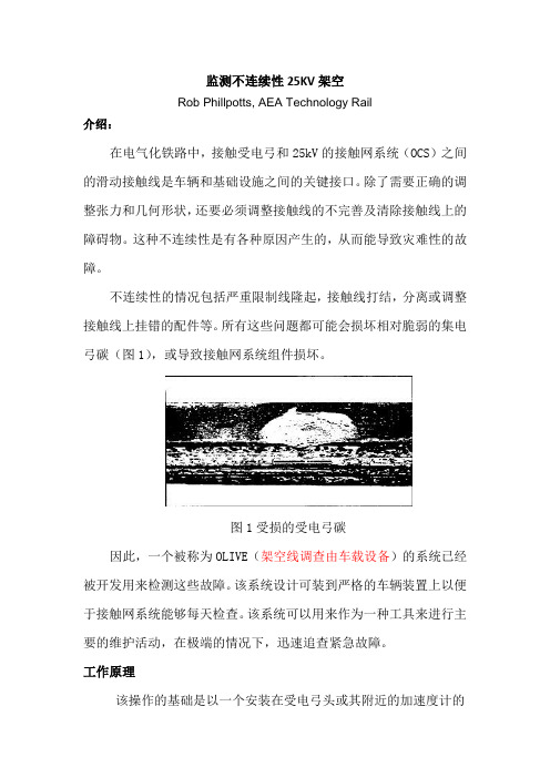
监测不连续性25KV架空Rob Phillpotts, AEA Technology Rail介绍:在电气化铁路中,接触受电弓和25kV的接触网系统(OCS)之间的滑动接触线是车辆和基础设施之间的关键接口。
除了需要正确的调整张力和几何形状,还要必须调整接触线的不完善及清除接触线上的障碍物。
这种不连续性是有各种原因产生的,从而能导致灾难性的故障。
不连续性的情况包括严重限制线隆起,接触线打结,分离或调整接触线上挂错的配件等。
所有这些问题都可能会损坏相对脆弱的集电弓碳(图1),或导致接触网系统组件损坏。
图1受损的受电弓碳因此,一个被称为OLIVE(架空线调查由车载设备)的系统已经被开发用来检测这些故障。
该系统设计可装到严格的车辆装置上以便于接触网系统能够每天检查。
该系统可以用来作为一种工具来进行主要的维护活动,在极端的情况下,迅速追查紧急故障。
工作原理该操作的基础是以一个安装在受电弓头或其附近的加速度计的装置来检测。
从加速度计的信号连续监测,每当一个预设加速水平超出地域的位置被记录下来。
在OCS的位置这些异常大的干扰受电弓头发生被称为影响在间断的位置,而且指示接触线。
系统组件图2示出了示意性的OLIVE安装。
它包括安装的受电弓上的加速度计,车辆内的信号线,信号空调机组和主处理器单元。
主要处理器采用了全球定位系统(GPS)导航器单元毛皮影响位置和蜂窝电话,使数据传输到报告中心。
图2 OLIVF,车辆装备可选组件的基本制度是“坎开关安装在受电弓头检测接触的电线上运行的实例受电弓角,转速计/曲目磁铁投入,以提高定位精度。
加速度计和高阶交换机是光纤设备。
光纤传感器的使用与电子传感器在长期使用上比较更具优势:●低维护 - 没有“活方”电子与相关的力,安装到受电弓用相关的电力来维持运行。
●他可以提高固有电噪声的免疫力,降低从受电弓上受到的电弧干扰,否则会导致杂散信号。
●无电气噪声滤波是必需的,完整的传感器的带宽是可用的 -一个加速度计几百赫兹的反应是必需的。
铁道方向毕业文献翻译
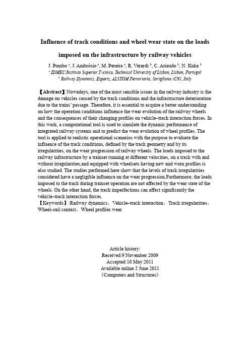
Influence of track conditions and wheel wear state on the loads imposed on the infrastructure by railway vehicles J. Pombo a,J. Ambrósio a, M. Pereira a, R. Verardi b, C. Ariaudo b, N. Kuka ba IDMEC/Instituto Superior Técnico, Technical University of Lisbon, Lisbon, Portugalb Railway Dynamics, Experts, ALSTOM Ferroviaria, Savigliano (CN), Italy【Abstract】Nowadays, one of the most sensible issues in the railway industry is the damage on vehicles caused by the track conditions and the infrastructure deterioration due to the trains’ passage. Therefore, it is essential to acquire a better understanding on how the operation conditions influence the wear evolution of the railway wheels and the consequences of their changing profiles on vehicle–track interaction forces. In this work, a computational tool is used to simulate the dynamic performance of integrated railway systems and to predict the wear evolution of wheel profiles. The tool is applied to realistic operational scenarios with the purpose to evaluate the influence of the track conditions, defined by the track geometry and by its irregularities, on the wear progression of railway wheels. The loads imposed to the railway infrastructure by a trainset running at different velocities, on a track with and without irregularities,and equipped with wheelsets having new and worn profiles is also studied. The studies performed here show that the levels of track irregularities considered have a negligible influence on the wear progression.Furthermore, the loads imposed to the track during trainset operation are not affected by the wear state of the wheels. On the other hand, the track imperfections can affect significantly the vehicle–track interaction forces.【Keywords】:Railway dynamics,Vehicle–track interaction,Track irregularities,Wheel–rail contact,Wheel profiles wearArticle history:Received 9 November 2009Accepted 10 May 2011Available online 2 June 2011《Computers and Structures》1.IntroductionThe dynamic analysis of the loads imposed to the railway infrastructure by trainsets and, conversely, the damages on vehicles provoked by the track conditions has been attracting the attention of railway community in recent years. The raising interest on this subject has occurred mainly due to the development of new high-speed railway lines and to the common drive to upgrade the existing infrastructures. The increasing demands on railway transportation require improvements of the network capacity, which can be achieved either by increasing the speed of the traffic or by increasing the axle loads. However, both of these options place pressures on the existing infrastructures and the effects of these changes have to be carefully considered.In general, the increasing demand for safer, more efficient and better cost-effective railway transport is satisfied by two alternative approaches. In the first one, dedicated high-speed lines are built to carry passenger-only traffic (e.g. France and Japan) or mixed passenger-freight traffic (e.g. Germany, Italy and UK). This approach significantly increases the lines capacity as the traditional tracks can be freed of the intercity passenger trains, leaving more room for freight and regional passenger traffic. Nevertheless, this solution is also very costly as it requires building completely new high-quality lines with the accompanying infrastructure.A second alternative approach consists of upgrading the existing infrastructures to allow for faster passenger trains and heavier freight trains. This approach was adopted, for instance, in Sweden (Stockholm–Malmo line) and in the UK (West Coast Main Line from London to Glasgow) where tilting passenger trains operate on modernised tracks at speeds up to 200 km/h. Despite this solution is much less efficient in terms of increasing the line capacity, it is used when the efficiency improvements are required within a shorter time-frame or when the demand does not justify high expenses on building new lines.The latter approach is currently being implemented in several European countries (e.g. Portugal and Ireland) where the railway networks are undergoing modernisation to cope with the ever increasing demand on railway transportation. However, a great part of these infrastructures date back to the second half of the 19th century and to the first half of the 20th. Clearly, they were designed to carry loads different from those they are subjected to today. Furthermore, the dynamic effects were not fully recognized and appreciated at the time the structures were designed and built. This raises concerns regarding the dynamic response of these tracks caused by the current and planned enhancements of the network capacity. In particular, the dynamic effects caused by the increase in the speed and axle loads of trains and by the introduction of new types of the rolling stock are under question. These dynamic effects include excessive vibrations, risk of resonance, stability of the track and running safety of rolling stock, among others.The improvement of the modelling capabilities and the understanding of the dynamic response of vehicle–track interaction can provide refined methods of analysis and assessment of existing railway systems. These, will help to address the ageing problems of rolling stock and of infrastructures and will allow the development of more cost-efficient maintenance and modernisation procedures. In addition, enhancements to the capacity of railway networks can be achieved if the dynamic effects, resulting from increased speeds and loads of trains, are accurately predicted and evaluated.During trainset operation, the wheels of railway vehicles are subjected to wear. When the worn state of the profiles reaches a limit value defined by international standards [1], the wheels have to be re-profiled. Furthermore, the railway wheels only can be re-profiled 3 or 4 times and the wheelset substitution is a very expensive maintenance procedure. Therefore, it is also important to acquire a better understanding on how the track conditions influence the wear evolution and the vehicle-track interaction forces. Such evaluation is an important contribute to reduce the operation and maintenance costs, by increasing the life cycle of both vehicles and tracks.In the literature, several approaches to estimate wheel and rail ear using dynamic simulations are available [2–6]. However, less emphasis has been placed on the consequences of that wear on the performance of the railway vehicles and on the loads imposed to the infrastructure. The work reported by Nielsen et al. [7] focus on the train-track interaction and mechanisms of irregular wear. These authors discuss the causes, consequences and suggest solutions to minimize the problems for several types of wheel and rail wear. Hur et al. [8] use a 1/5 scaled roller rig bogie prototype to analyze the influence of the wheel profile wear on the running stability (critical speed) of railway vehicles. Froling [9] addresses the asymmetric wheel profile wear and analyses the consequential damages to the wheels, rails, turnouts and bogie components. Wu [10] discusses the effects of wheel and rail profiles on vehicle curving and lateral stability through the evaluation of the North American freight railways wheel profile. Fergusson et al. [11] tackle the wheel wear problem in another perspective. They present a methodology to minimize the wheel wear by optimising the primary suspension stiffness and the centre plate friction of a self-steering three-piece bogie without compromising the vehicle stability.In the work presented here, a computational tool, based on a multibody formulation, is used to simulate the dynamic performance of integrated railway systems that include the vehicle, the track and their interaction. The tool is also able to predict the wear evolution of the wheel profiles as a function of the distance run. In this work, the tool is first applied to realistic operational scenarios in order to study how the wheel wear progression is affected by the track conditions, defined by its geometry and irregularities. Then, special attention is given to the comparison of the vehicle-track interaction forces obtained during the operation of a trainset, running atdifferent velocities, on tracks with and without irregularities. These simulations are performed with the railway vehicle assembled with wheels having new and worn profiles in order to evaluate how the wear state influences the loads transmitted to the railway infrastructure.2.Description of the computational toolThe computational tool used here is composed of two parts. The first one is the railway dynamics block that uses the commercial software V AMPIRE [12,13] to study the dynamic behaviour of railway vehicles. This software uses a multibody formulation [14–19] to simulate the dynamic performance of integrated railway systems that include the vehicle, the track and the wheel–rail contact interaction. The code allows simulating accurately the vehicle, including the masses and inertias of the structural elements, and the characteristics of suspensions. It is also possible to represent accurately the track geometry, which is defined by its layout (macro-geometry) and by the track irregularities. This allows including, in the railway dynamic studies, the perturbations arising from the track imperfections. The vehicle–track interaction is studied through an appropriate wheel–rail contact formulation [20–26]that is used to compute the normal and tangential forces that develop in the contact area. Here, in particular, the fully non-linear creep law from V AMPIRE tool [12,13], with non-linear contact forces and non-linear contact geometry, is used.The second block of the computational tool is a purpose-built code [27–31] that is used to manage the pre and post-processing data of the first block in order to compute the wheel profiles wear or a given railway system. The strategy consists of providing an initial profile to all wheels of the trainset and running a simulation, for a pre-defined travel distance using the commercial multibody software. Then, the wear prediction block collects the necessary data from the dynamic analysis results and calculates the wear, i.e. the amount of material to be removed from the wheel surfaces. The resulting updated profiles are then used as input for a new railway dynamic analysis. This methodology, represented in Fig. 1, is repeated as many times as necessary to reach the distance required for the wear study.Fig. 1. Outline of the computational tool.The core of the wear prediction block is the wear computation rocedure thatcalculates the amount of worn material to be removed from the wheel surfaces. This block is composed of the contact model and of the wear function. The contact model processes the dynamic analysis results to obtain the wheel-rail contact parameters. The wear function uses these contact parameters as input to compute the quantity of worn material to be removed from the wheel surfaces.3.Influence of track conditions on wheels wearIn the following, the computational tool described here is used to evaluate the influence that the track conditions, defined by its geometry and irregularities, have on the wear evolution of railway wheels.3.1.Railway vehicleThe 3D model of the railway vehicle is build using a multibody approach [14–19]. This methodology allows representing accurately the mass and inertia properties of the structural elements that compose the vehicle. It also includes the kinematic joints, which control the relative motion between the bodies, and the force elements, that represent suspension components of vehicle.The trainset considered for the studies conducted here is a nonarticulated conventional trainset composed by seven vehicles interconnected by linking elements, as represented in Fig. 2.Fig. 2. Non-articulated conventional trainset.Due to the trainset configuration, it is assumed that, concerning the studies performed here, the dynamic behaviour of each vehicle has a non-significant influence on the others. According to this assumption, each vehicle of the trainset can be studied independently, as shown in Fig. 3. In this way, the vehicle model considered is composed only by one unit of the trainset. This composition is a motor vehicle that is assembled with two trailer wheelsets, represented in white in Fig. 3 and two motor wheelsets, represented in black. The vehicle is initially equipped with new wheels, having a diameter of 890 mm and a S1002 profile [1].Fig. 3. Motor vehicle of trainset3.2.Track conditionsThe dynamics behaviour of railway vehicles is dependent, on a great extent, of the track conditions. Also the loads transmitted to the infrastructure by the trainsets operation depend on the track geometry. The accurate description of the track is, therefore, essential for the dynamic analysis of railway systems.The computational tool used here allows creating realistic track models to run the railway dynamic studies. The track geometry is defined by the track layout, representing its macro-geometry, and by the track irregularities, representing its imperfections.3.2.1.Track layoutThe railway tracks are, in general, composed of straight (or tangent) sections, transition curves and circular curves. In the computational tool used here, the track layout is defined by the following design parameters [12,13]: (a) plan view curvature;(b) vertical offset; and (c) cross level offset. The plan view curvature c represents the curvature of the track in the horizontal plane, being defined as:c=1R(1) where R is the radius of the curve, as represented in Fig. 4a).When travelling in horizontal curves, railway vehicles are influenced by centrifugal forces, which act in a direction away from the center of the curve and tend to overturn the vehicles. In order to counteract this force, the outer rail in a curve is raised. This difference of heights between the two rails is called cross level offset h (or cant). The vertical offset zO represents the height of the track centerline in a curve. These two parameters are represented in Fig. 4(b).Fig. 4. Parameters to define the track layout: (a) plan view curvature; (b) vertical offset and cross level offset (cant).The track considered for the wear studies conducted here is from the Italian railway network, between the cities of Cuneo and Ventimiglia. This track has about 96 km length and it is particularly curved, with 61% of its curves having radii with less than 450 m, as represented in Fig. 5.Fig. 5. Curve radii distribution of the Cuneo–Ventimiglia track.The track model is assembled with UIC60 rails [32], with 1/20 cant, and has a track gauge of 1435 mm. The track flexibility is modelled here differently in the vertical and lateral directions. Laterally the rails can move independently of the sleepers, as represented in Fig. 6. The lateral model thus has rail to sleeper lateral flexibility as well as sleeper to ground flexibility. Vertically the rails are constrained to the sleepers and so the track model just has a vertical flexibility to ground. The track flexibility is represented here by stiffness and damping parameters with the following characteristics [12,13]:●Track stiffness:❍Sleeper-ground lateral stiffness: ky = 37.0 * 106 N/m.❍Rail-sleeper lateral stiffness: kr-y = 43.0 * 106 N/m.❍Sleeper-ground vertical stiffness: kz = 50.0 * 106 N/m.●Track damping:❍Sleeper-ground lateral damping: cy = 0.24 * 106 N s/m.❍Rail-sleeper lateral damping: cr-y = 0.24 * 106 N s/m.❍Sleeper-ground vertical damping: cz = 0.1 * 106 N s/m.Fig. 6. Track stiffness and damping.3.2.2.Track irregularitiesThe realistic description of a track requires not only the definition of its layout, as previously referred, but also the description of the irregularities. This data represents the deviations of the track from its design geometry and result mainly from construction imperfections, usage operations and change on the foundations. In the railway industry, the track irregularities are measured experimentally using special testing vehicles.In the studies carried out in this work, the track imperfections are characterized by several parameters [12,13]: (a) cross level (cant) irregularities; (b) curvature irregularities; (c) lateral irregularities; (d) vertical irregularities; and (e) gauge variation. The curvature irregularities contain the long wavelength lateral data,while the lateral irregularities define the short wavelength lateral displacements [12,13]. During the dynamic analysis, the railway vehicle follows the curvature data but not the lateral irregularity. The gauge variation gives the variation of the gauge about the nominal value and a positive value indicates increasing gauge.In Fig. 7 the absolute measured values of the irregularities parameters are presented for the first 2 km of the track. These values are representative of the irregularities that exist along the 96 km of track length. With the inclusion of irregularities in the whole track model, the complete characterization of the track Fig. 2. Non-articulated conventional trainset. Fig. 3. Motor vehicle of trainset.conditions is achieved. This allows performing railway dynamic studies considering the track perturbations.Fig. 7. Track irregularities parameters for the first 2000 m of track: (a) cross level (cant) irregularities; (b) curvature irregularities; (c) lateral irregularities; (d) vertical irregularities; (e) gauge variation.3.3.Wear study on the wheels of railway vehiclesIn order to evaluate the influence of the track imperfections on the wear evolution, two wear studies are carried out. In the first one, an ideal track model is considered, having a perfect design geometry, defined in Fig. 5, with no irregularities. In the second wear study, a realistic track model is adopted having the same layout of the previous one, but considering the measured track irregularities represented in Fig. 7. In both cases all remaining input data, used to study the railway dynamic problem, and analysis parameters, required for the wear computations, are equal.The comparative wear studies are carried out by performing several journeys of railway vehicle on both tracks until reaching the total distance of 5000 km. The vehicle velocity is defined according to the service conditions, varying between 80 and 95 km/h along the track length.The new and the worn profiles obtained in the two tracks, with and without irregularities, are presented in Fig. 8. These results correspond to the left and right wheels of leading wheelset. From these plots, no differences are perceptible among results obtained with the two tracks. In order to assess the differences with more detail,the wear depth results on the profiles of both wheels are also analysed.The comparison between the wear depth values obtained when travelling on the two tracks is shown in Fig. 9. The results are presented as a percentage of the maximum wear depth value obtained on both wheels. In this comparative study, no significant differences are observed between the wear depth results obtained with the tracks with and without irregularities. This means that the levels of imperfections considered in this track, represented in Fig. 7, do not affect the wear progression on the trainset wheels when operating this line. In other work by the same authors [28], a comparative wear study between two tracks with different layouts is performed. In that work it is demonstrated that the severed curved track, considered here and having the design characteristics represented in Fig. 5, originates levels of wear 20–40% higher than the ones obtained in a track with a mainly straight geometry.From Fig. 9 it is also interesting to note that the wear distribution along the profiles is slightly wider when travelling on the track with irregularities. This can be explained by the fact that the track imperfections originate more lateral oscillations of the wheelsets during trainset operation. Consequently, the lateral position of the wheel–rail contact points along the profiles has more amplitude. The wear results also show that, after 5000 km of trainset operation, the highest wear on the left wheel occurs on both tread and flange zones, while, on the right wheel, it occurs on flange.Fig. 8. Influence of track irregularities on wear: (a) Left wheel; (b) right wheel.4.Influence of wheel wear and of track irregularities on track loadsAn important and very sensitive issue in railway industry is the impact of train operations on the infrastructure and, conversely, the damages on vehicles provoked by the track conditions. This topic has a significant economical impact on the vehicles maintenance but also affects the life cycle costs of tracks. As a consequence, there is a growing tendency to define the track access charges, i.e. the prices billed by the infrastructure managers to the railway operators, according to the damage that the trainsets operation is supposed to cause to the tracks.In the following, the dynamic behaviour of a railway vehicle is studied in several service conditions. The purpose is to assess how the wear state of its wheels and the track imperfections influence the loads imposed to the infrastructure. These studies are performed considering different velocities for the trainset operation.Fig. 9. Wear depth results on: (a) left wheel; (b) right wheel.4.1.Railway vehicleThe railway vehicle used in the studies conducted here is represented in Fig. 3. It is the same as the one considered in the wear evolution studies described in the previous section.4.2.Track conditions4.2.1.Track layoutA section of the track described previously, and represented in Fig. 5, is considered here to study the influence of the wheel wear state and of track irregularities on track loads. The design geometry of this track section is depicted in Fig. 10. It corresponds to the first 2000 m between Cuneo and Ventimiglia, which is representative of the whole railway network between these two cities. The track layout is composed of a straight segment L1 followed by two circular curves L3 and L5, with radii R1 and R2, respectively, and finalized by a tangent segment L7.When trains are operated at normal speeds, a circular curve with cant cannot be followed directly by a tangent track, and vice-versa [20,21]. A transition between these two types of segments, designated by transition curve, is required in order to guarantee the curvature continuity and to minimize the change of lateral accelerations of the vehicles. Usually, the radius of a transition curve is changed continuously, decreasing from an infinite radius, at the tangent end, to a radius equal to that of the circular curve, at the other end. The transition curves are also used between circular curves with different radius. In Fig. 10 the track segments L2, L4 and L6, represented with dashed lines, are the transition curves of the track considered here.Also the cant is changed gradually over the transition length, leading to the so-called superelevation ramp. It represents the cant variation along the transition, ensuring a smooth cant evolution from a null value, at the straight track, to the nominal cant of the circular curve. The design characteristics of the track depicted in Fig. 10 are represented in Table 1.Fig. 10. Track layout.Table 1Design characteristics of the track.4.2.2.Track irregularitiesThe imperfections associated to the track layout depicted in Fig. 10 are also considered here. They are defined by the track irregularities parameters described before in this text and represented in Fig. 7.4.3.Influence of wheel wear state on track loadsThe purpose here is to analyse the dynamic behaviour of the railway vehicle in different operation conditions in order to assess how the wear state of its wheels influence the loads imposed to the infrastructure. For this purpose, the vehicle is assembled with wheelsets having the new and the worn wheel profiles, represented in Fig. 11, and comparative dynamic studies are carried out.The comparative studies with new and worn wheels are performed considering two different velocities for the trainset. The velocity of 95 km/h is adopted as it corresponds to the service conditions of the vehicle in this 2000 m section of the track.The velocity of 135 km/h is also considered since it represents the maximum velocity that a railway vehicle can operate a track having curves with the design characteristics presented in Table 1 [33].Fig. 11. New and worn wheel profiles: (a) left wheel; (b) right wheel.4.3.1.Track loads caused by the leading wheelsetThe first indicator considered here to assess the loads imposed to the track by the trainset operation is the wheelset ripage force FRipage. This force represents the total lateral force transmitted to the track by a wheelset, being obtained as the sum of the lateral contact forces exerted on the left and right rails. These forces are represented in Fig. 12 for the cases in which the wheelset is running on a straight track or negotiating a curve.The ripage force results, originated by the leading wheelset of the railway vehicle, are presented in Fig. 13. These results are obtained for running velocities of 95 and 135 km/h and with the vehicle assembled with new and worn wheels. According to the UIC 518 standard [33], these results should have two steps of signal post-processing. First, the lateral track forces data is processed with a sliding window 2 m running average filter. Then, a low pass filter with a cut-off frequency of 20 Hz and 2 poles is used to obtain the final results for the ripage force.The results from Fig. 13 show that, in curve, the lateral track forces obtained with the velocity of 135 km/h are about 150% higher than when running at 95 km/h. When comparing the results obtained with new and worn profiles, it is observed that the new wheels originate slightly higher lateral track forces on curve.It is also interesting to observe that in the tangent track after the curve, the vehicle assembled with new wheels and running at the velocity of 135 km/h exhibits a periodic lateral oscillation that originates low frequency lateral track forces. This phenomenon is known in the railway industry as vehicle lower sway and it only occurs when using new wheel profiles S1002 and new rail profiles UIC 60 with 1/20 cant. In such conditions, the equivalent conicity [20,34,35] of the wheelsets is very small and, consequently, after a perturbation the vehicle has more difficulty to center itself on the track. This phenomenon does not occur when using the worn wheel profiles since the equivalent conicity is higher and the wheelsets have a stronger tendency to center themselves on the track.Another indicator considered to evaluate the loads imposed to the track by the trainset operation is the vertical wheelset force on the left FL and on the right FR rails. These forces are represented in Fig. 12 for the cases in which the wheelset is running on straight and curved tracks.The vertical track forces results obtained on the left and right rails are presented in Figs. 14 and 15 , respectively. These results are defined in the wheelset axis and are filtered with a low pass filter with a cut-off frequency of 20 Hz and 2 poles, according to the UIC 518 standard [33]. When comparing the results obtained with new and worn profiles, no differences are perceptible among them. This means that the vertical track forces are not sensitive to the wear state of the wheels.The graphs of the vertical track forces also show that, in curve, the track forces on the inner (left) rail are lower when running with the velocity of 135 km/h. On the outer (right) rail, the opposite happens, i.e. the higher velocity originates higher vertical forces. These results show that the railway vehicle is running with cant deficiency, which is more pronounced at 135 km/h. This means that, for these velocities, the track cant is not sufficient to assure zero track plane acceleration and a resultant centrifugal force arises, pointing towards outside of the curve. Consequently, the passengers are pushed in that direction and the vertical contact forces are higher on the outer wheels.Fig. 12. Ripage (lateral) and vertical wheelset forces transmitted to the track: (a) tangent track; (b) curved track.。
毕业设计英文文献翻译(电力方向附带中文)
毕业设计英文文献翻译(电力方向附带中文)大学毕业设计英文文献翻译,关于电力系统方向,电力谐波!绝对原创!HarmonicsService reliability and quality of power have become growing concerns for many facility managers, especially with the increasing sensitivity of electronic equipment and automated controls. There are several types of voltage fluctuations that can cause problems, including surges and spikes, sags, harmonic distortion, and momentary disruptions. Harmonics can cause sensitive equipment to malfunction and other problems, including overheating of transformers and wiring, nuisance breaker trips, and reduced power factor.What Are Harmonics?Harmonics are voltage and current frequencies riding on top of the normal sinusoidal voltage and current waveforms. Usually these harmonic frequencies are in multiples of the fundamental frequency, which is 60 hertz (Hz) in the US and Canada. The mostcommon source of harmonic distortion is electronic equipment using switch-mode power supplies, such as computers, adjustable-speed drives, and high-efficiency electronic light ballasts.Harmonics are created by these Dswitching loads‖ (also called “nonlinear loads,‖ because current does not vary smoothly with voltage as it does with simple resistive and reactive loads): Each time the current is switched on and off, a current pulse is created. The resulting pulsed waveform is made up of a spectrum of harmonic frequencies, including the 60 Hz fundamental and multiples of it. This voltage distortion typically results from distortion in the current reacting with system impedance. (Impedance is a measure of the total opposi tion―resistance, capacitance, and inductance―to the flow of an alternating current.) The higher-frequency waveforms, collectively referred to as total harmonic distortion (THD), perform no useful work and can be asignificant nuisance.Harmonic waveforms are characterized by their amplitude and harmonic number. In the U.S. and Canada, the third harmonic is 180 Hz―or 3 x 60 Hz―and the fifth harmonic is 300 Hz (5 x 60Hz). The third harmonic (and multiples of it) is the largest problem in circuits with single-phase loads such as computers and fax machines. Figure 1 shows how the 60-Hz alternating current (AC) voltage waveform changes when harmonics are added.大学毕业设计英文文献翻译,关于电力系统方向,电力谐波!绝对原创!The Problem with HarmonicsAny distribution circuit serving modern electronic devices will contain some degree of harmonic frequencies. The harmonics do not always cause problems, but the greater the power drawn by these modern devices or other nonlinear loads, the greater the level of voltage distortion. Potential problems (or symptoms of problems) attributed to harmonics include:■ Malfunction of sensitive equipment■ Random tripping of circuit breakers■ Flickering lights■ Very high neutral currents■ Overheated phase conductors, panels, and transformers ■ Premature failure of transformers and uninterruptible power supplies (UPSs)■ Reduced power factor■ Reduced system capacity (because harmonics create additional heat, transformers and otherdistribution equipment cannot carry full rated load)Identifying the ProblemWithout obvious symptoms such as nuisance breaker trips or overheated transformers, how do you determine whether harmonic current or voltages are a cause for concern? Here are several suggestions for simple, inexpensive measurements that a facility manager or staff electrician could take, starting at the outlet and moving upstream:■ Measure the peak and root mean square (RMS) voltage at a sample of receptacles. The Dcrest factor‖ is the ra tio of peak to RMS voltage. For a perfectly sinusoidal voltage, the crest factor will be 1.4. Low crest factor is a clear indicator of the presence of harmonics. Note that these measurements must be performed with a Dtrue RMS‖ meter―one that doesn‘t assume a perfectly sinusoidal waveform.■ Inspect distribution panels. Remove panel covers and visually inspect components for signs of overheating, including discolored or receded insulation or discoloration of terminal screws. If you see any of these symptoms, check that connectionsare tight (since loose connections could also cause overheating), and compare currents in all conductors to their ratings.■ Measure phase and neutral currents at the transformer secondary with clamp-on current probes. If no harmonics are being generated, the neutral current of a three-phase distribution system carries only the imbalance of the phase currents. In a well-balanced three-phase distribution system, phase currents will be very similar, and current in the neutral conductor should be much lower than phase current and far below its rated current capacity. If phase currents are similar and neutral current exceeds their imbalance by a wide margin, harmonics are present. If neutral current is above 70 percent of the cond uctor‘s rated capacity, you need to mitigate the problem.■Compare transformer temperature and loading with nameplate temperature rise and capacity ratings. Even lightly loaded transformers can overheat if harmonic current is high. A transformer that is near or over its rated temperature rise but is loaded well below its rated capacity is a clear sign that harmonics are at work. (Many transformers have built-in temperature gauges. If yours does not, infrared thermography can be used to detect overheating.)大学毕业设计英文文献翻译,关于电力系统方向,电力谐波!绝对原创!In addition to these simple measurements, many power-monitoring devices are now commercially available from a variety of manufacturers to measure and record harmonic levels. These instruments provide detailed information on THD, as well as on the intensity of individual harmonic frequencies. After taking the appropriate measurements to determine whether you have high levels of harmonics and, if so, to find the source, you will be well-positioned to choose the best solution.Solutions to Harmonics ProblemsThe best way to deal with harmonics problems is through prevention: choosing equipment and installation practices that minimize the level of harmonics in any one circuit or portion of a facility. Many power quality problems, including those resulting from harmonics, occur when new equipment is haphazardly added to older systems. However, even within existing facilities, the problems can often be solved with simple solutions such as fixing poor or nonexistent grounding on individual equipment or the facility as a whole, moving a few loads between branch circuits, or adding additional circuits to help isolate the sensitiveequipment from what is causing the harmonic distortion. If the problems cannot be solved by these simple measures, there are two basic choices: to reinforce the distribution system to withstand the harmonics or to install devices to attenuate or remove the harmonics. Reinforcing the distribution system means installing double-size neutral wires or installing separate neutral wires for each phase, and/or installing oversized or Krated transformers, which allow for more heat dissipation. There are also harmonic-rated circuit breakers and panels, which are designed to prevent overheating due to harmonics. This option is generally more suited to new facilities, because the costs of retrofitting an existing facility in this way could be significant. Strategies for attenuating harmonics, from cheap to more expensive, include passive harmonic filters, isolation transformers, harmonic mitigating transformers (HMTs), the Harmonic Suppression System (HSS) from Harmonics Ltd., and active filters(Table 1).Passive filters (also called traps) include devices that provide low-impedance paths to divert harmonics to ground and devices that create a higher-impedance path to discourage the flow of harmonics. Both of these devices, by necessity, change theimpedance characteristics of the circuits into which they are inserted. Another weakness of passive harmonic technologies is that, as their name implies, they cannot adapt to changes in the electrical systems in which they operate. This means that changes to the electrical system (for example, the addition or removal of power factorCcorrection capacitors or the addition of more nonlinear loads) could cause them to be overloaded or to create Dresonances‖ that could actually amplify, rather than diminish, harmonics.Active harmonic filters, in contrast, continuously adjust their behavior in response to the harmonic current content of the monitored circuit, and they will not cause resonance. Like an automatic transmission in a car, active filters are designed to accommodate a full range of expected operating conditions upon installation, without requiring further adjustments by the operator.Isolation transformers are filtering devices that segregate harmonics in the circuit in which they are created, protecting upstream equipment from the effects of harmonics. These transformers do not remove the problem in the circuit generating the harmonics, but they can prevent the harmonics from affecting more sensitive equipment elsewhere within the facility.大学毕业设计英文文献翻译,关于电力系统方向,电力谐波!绝对原创!Harmonic mitigating transformers actually do relieve problematic harmonics. HMTs can be quite cost-effective in the right application, because they can both improve reliability and reduce energy costs. The right application includes transformers that are heavily or moderately loaded and where high levels of harmonic currents are present. In addition, HMTs are very effective in supporting critical loads that are backed up by a UPS. UPSs and backup generators tend to have high impedance, which results in high voltage distortion under nonlinear loading. Because of this, equipment that operates flawlessly when supplied by utility power may malfunction when the backup system engages during a utility outage. Note that some of these power systems have output filters (either passive or active) to control harmonic levels. The presence or absence of such filters should be determined before adding an HMT.The Harmonics Ltd. Harmonic Suppression System is a unique solution for single-phase loads that is designed to suppress the third harmonic. An HSS is generally more expensive than an HMT, but it is designed to attenuate the harmonicsproblems throughout the entire distribution system, not just upstream of the transformer. The types of facilities that present the best opportunities for HSS installation are those that place a very high premium on power quality and reliability, such as server farms, radio and television broadcast studios, and hospitals. (See .) Economic EvaluationEvaluating the life-cycle costs and effectiveness of harmonics mitigation technologies can be ve ry challenging―beyond the expertise of most industrial facility managers. After performing the proper measurement and analysis of the harmonics problem, this type of evaluation requires an analysis of the costs of the harmonics problem (downtime of sensitive equipment, reduced power factor, energy losses or potential energy savings) and the costs of the solutions. A good place to start in performing this type of analysis is to ask your local utility or electricity provider for assistance. Many utilities offer their own power quality mitigation services or can refer you to outside power quality service providers.Additional ResourcesInstitute of Electrical and Electronics Engineers (IEEE),Standard 519-1992, DIEEE大学毕业设计英文文献翻译,关于电力系统方向,电力谐波!绝对原创!Recommended Practices and Requirements for Harmonic Control in Electric Power Systems‖ (1992), available at .Relationship between harmonics and symmetrical componentsAbstract New terminology is introduced to make clear the relationship between harmonics and symmetrical components. Three-phase sets are classified in terms of symmetrical sets and asymmetrical sets. Subclasses are introduced with the names symmetrical balanced sets, symmetrical unbalanced sets, asymmetrical balanced sets and asymmetrical unbalanced sets to show that a threephase set can resolve to either one, two or three symmetrical component sets. The results from four case studies show that these subclasses and their resolution to symmetrical component sets improve understanding of harmonic analysis of systems having balanced and unbalanced harmonic sources and loads.Keywords asymmetrical sets; harmonic flows; harmonic sources; symmetrical component sets; symmetrical sets Any periodic wave shape can be broken down into oranalysed as a fundamentalwave and a series of harmonics.Three-phase harmonic analysis requires a clear understanding of the relationship between symmetrical component injections from harmonic sources (e.g. adjustable speed drives, ASDs) and their relationship to harmonic flows (symmetrical components) arising from the application of a harmonic source to a linear system.Alimited number of references contain brief information concerning harmonics and symmetrical components. Reference 1, provides a paragraph on this topic and uses the heading Relationship between Harmonics and Symmetrical Components‘.It includes a table that is supported by a brief explanatory paragraph. The table expresses harmonics in terms of positive, negative and zero sequences. It states that these sequences are for harmonics in balanced three-phase systems. The heading refers to symmetrical components while the content refers to balanced three-phase systems. Herein lies the anomaly. Classically, symmetrical components (especially ero sequence) are only applied in unbalanced systems. The following questions rose after reading the Ref. 1 paragraph.(a)Do symmetrical components (especially zero sequence), in the classical sense,apply in balanced as well as unbalanced non-sinusoidal systems and is this abreak from tradition?(b)What do the terms, symmetrical, asymmetrical, balanced, unbalanced andsymmetrical components mean?(c)What are the conditions under which a system must operate so that harmonicsresolve to positive, negative and zero sequences and is the table given inRef. 1 correct?The terminology used is found inadequate for describing non-sinusoidal systems.There is thus a need to introduce a three-phase terminology that will show the relationship and make the comparison between injections (currents) and harmonic flows (voltages and currents) meaningful.References 3 provides the basis for the solution by providing definitions for threephase sets‘, symmetrical sets‘an d symmetricalcomponent sets‘.The purpose of this paper is to introduce an approach to harmonic analysis大学毕业设计英文文献翻译,关于电力系统方向,电力谐波!绝对原创!based on the classification of three-phase sets and to make to comparison between injections from harmonic sources and corresponding harmonic flows quantifiable by expressing the results in terms of the number of symmetrical component sets found.Harmonic flows and their resolution to symmetrical components depends upon the magnitudes and phase sequences of the injections from a harmonic source, on the system‘s sequence impedances, on three- and four-wire connections and on whether the customer‘s linear load on the system is balanced or unbalanced. Therefore, what is injected in terms of symmetrical component sets by a harmonic source is not necessarily received by the system, i.e. the harmonic flows may resolve to one, two or three symmetrical component sets and this depends upon the type of three-phase set found. Therefore, any three-phase harmonic may be partially made up of any of thesymmetrical component sets.Four case studies are reported and they show a novel method for teaching the flow of power system harmonics. It is important to use case studies as part of one‘s teaching as they link learning to concepts and improve understanding. They show how the method of symmetrical components can be extended to a system‘s response to harmonic flows. When taught as a group, the four case studies improve cognitive skills by showing that the symmetrical component responses under unbalanced situations are different to the balanced state.IEEE __TIONS ON POWER __NICS VOL.19,NO.3,__年大学毕业设计英文文献翻译,关于电力系统方向,电力谐波!绝对原创!谐波服务的可靠性和电能质量已成为越来越多设施经理的关注,尤其是随着电子设备和自动化控制灵敏度提高了很多。
电气专业毕业论文英文文献及翻译(附原文)-基于GPRS的智能交通系统.

毕业设计(论文)外文资料翻译外文原文Traffic Assignment Forecast Model Research in ITS IntroductionThe intelligent transportation system (ITS) develops rapidly along with the city sustainable development, the digital city construction and the development of transportation. One of the main functions of the ITS is to improve transportation environment and alleviate the transportation jam, the most effective method to gain the aim is to forecast the traffic volume of the local network and the important nodes exactly with GIS function of path analysis and correlation mathematic methods, and this will lead a better planning of the traffic network. Traffic assignment forecast is an important phase of traffic volume forecast. It will assign the forecasted traffic to every way in the traffic sector. If the traffic volume of certain road is too big, which would bring on traffic jam, planners must consider the adoption of new roads or improving existing roads to alleviate the traffic congestion situation. This study attempts to present an improved traffic assignment forecast model, MPCC, based on analyzing the advantages and disadvantages of classic traffic assignment forecast models, and test the validity of the improved model in practice.1 Analysis of classic models1.1 Shortcut traffic assignmentShortcut traffic assignment is a static traffic assignment method. In this method, the traffic load impact in the vehicles’ travel is not considered, and the traffic impedance (travel time) is a constant. The traffic volume of every origination-destination couple will be assigned to the shortcut between the origination and destination, while the traffic volume of other roads in this sector is null. Thisassignment method has the advantage of simple calculation; however, unevendistribution of the traffic volume is its obvious shortcoming. Using this assignmentmethod, the assignment traffic volume will be concentrated on the shortcut, which isobviously not realistic. However, shortcut traffic assignment is the basis of all theother traffic assignment methods.1.2 Multi-ways probability assignmentIn reality, travelers always want to choose the shortcut to the destination, whichis called the shortcut factor; however, as the complexity of the traffic network, thepath chosen may not necessarily be the shortcut, which is called the random factor.Although every traveler hopes to follow the shortcut, there are some whose choice isnot the shortcut in fact. The shorter the path is, the greater the probability of beingchosen is; the longer the path is, the smaller the probability of being chosen is.Therefore, the multi-ways probability assignment model is guided by the LOGIT model:∑---=n j ii i F F p 1)exp()exp(θθ (1)Where i p is the probability of the path section i; i F is the travel time of thepath section i; θ is the transport decision parameter, which is calculated by the followprinciple: firstly, calculate the i p with different θ (from 0 to 1), then find the θwhich makes i p the most proximate to the actual i p .The shortcut factor and the random factor is considered in multi-ways probabilityassignment, therefore, the assignment result is more reasonable, but the relationshipbetween traffic impedance and traffic load and road capacity is not considered in thismethod, which leads to the assignment result is imprecise in more crowded trafficnetwork. We attempt to improve the accuracy through integrating the several elements above in one model-MPCC.2 Multi-ways probability and capacity constraint model2.1 Rational path aggregateIn order to make the improved model more reasonable in the application, theconcept of rational path aggregate has been proposed. The rational path aggregate,which is the foundation of MPCC model, constrains the calculation scope. Rationalpath aggregate refers to the aggregate of paths between starts and ends of the trafficsector, defined by inner nodes ascertained by the following rules: the distancebetween the next inner node and the start can not be shorter than the distance betweenthe current one and the start; at the same time, the distance between the next innernode and the end can not be longer than the distance between the current one and theend. The multi-ways probability assignment model will be only used in the rationalpath aggregate to assign the forecast traffic volume, and this will greatly enhance theapplicability of this model.2.2 Model assumption1) Traffic impedance is not a constant. It is decided by the vehicle characteristicand the current traffic situation.2) The traffic impedance which travelers estimate is random and imprecise.3) Every traveler chooses the path from respective rational path aggregate.Based on the assumptions above, we can use the MPCC model to assign thetraffic volume in the sector of origination-destination couples.2.3 Calculation of path traffic impedanceActually, travelers have different understanding to path traffic impedance, butgenerally, the travel cost, which is mainly made up of forecast travel time, travellength and forecast travel outlay, is considered the traffic impedance. Eq. (2) displaysthis relationship. a a a a F L T C γβα++= (2)Where a C is the traffic impedance of the path section a; a T is the forecast traveltime of the path section a; a L is the travel length of the path section a; a F is theforecast travel outlay of the path section a; α, β, γ are the weight value of that threeelements which impact the traffic impedance. For a certain path section, there aredifferent α, β and γ value for different vehicles. We can get the weighted average of α,β and γ of each path section from the statistic percent of each type of vehicle in thepath section.2.4 Chosen probability in MPCCActually, travelers always want to follow the best path (broad sense shortcut), butbecause of the impact of random factor, travelers just can choose the path which is ofthe smallest traffic impedance they estimate by themselves. It is the key point ofMPCC. According to the random utility theory of economics, if traffic impedance is considered as the negativeutility, the chosen probability rs p of origination-destinationpoints couple (r, s) should follow LOGIT model:∑---=n j jrs rs bC bC p 1)exp()exp( (3) where rs p is the chosen probability of the pathsection (r, s);rs C is the traffic impedance of the path sect-ion (r, s); j C is the trafficimpedance of each path section in the forecast traffic sector; b reflects the travelers’cognition to the traffic impedance of paths in the traffic sector, which has reverseratio to its deviation. If b → ∞ , the deviation of understanding extent of trafficimpedance approaches to 0. In this case, all the travelers will follow the path whichis of the smallest traffic impedance, which equals to the assignment results withShortcut Traffic Assignment. Contrarily, if b → 0, travelers ’ understanding error approaches infinity. In this case, the paths travelers choose are scattered. There is anobjection that b is of dimension in Eq.(3). Because the deviation of b should beknown before, it is difficult to determine the value of b. Therefore, Eq.(3) is improvedas follows:∑---=n j OD j OD rsrs C bC C bC p 1)exp()exp(,∑-=n j j OD C n C 11(4) Where OD C is the average of the traffic impedance of all the as-signed paths; bwhich is of no dimension, just has relationship to the rational path aggregate, ratherthan the traffic impedance. According to actual observation, the range of b which is anexperience value is generally between 3.00 to 4.00. For the more crowded cityinternal roads, b is normally between 3.00 and 3.50.2.5 Flow of MPCCMPCC model combines the idea of multi-ways probability assignment andFig.1 Flowchart of MPCC iterative capacity constraint traffic assignment.Firstly, we can get the geometric information of the road network and OD trafficvolume from related data. Then we determine the rational path aggregate with themethod which is explained in Section 2.1.Secondly, we can calculate the traffic impedance of each path section with Eq.(2),which is expatiated in Section 2.3.Thirdly, on the foundation of the traffic impedance of each path section, we cancalculate the respective forecast traffic volume of every path section with improvedLOGIT model (Eq.(4)) in Section 2.4, which is the key point of MPCC.Fourthly, through the calculation processabove, we can get the chosen probability andforecast traffic volume of each path section, but itis not the end. We must recalculate the trafficimpedance again in the new traffic volumesituation. As is shown in Fig.1, because of theconsideration of the relationship between trafficimpedance and traffic load, the traffic impedanceand forecast assignment traffic volume of everypath will be continually amended. Using therelationship model between average speed andtraffic volume, we can calculate the travel timeand the traffic impedance of certain path sect-ionunder different traffic volume situation. For theroads with different technical levels, therelationship models between average speeds totraffic volume are as follows: 1) Highway: 1082.049.179AN V = (5) 2) Level 1 Roads: 11433.084.155AN V = (6) 3) Level 2 Roads: 66.091.057.112AN V = (7) 4) Level 3 Roads: 3.132.01.99AN V = (8) 5) Level 4 Roads: 0988.05.70A N V =(9)Where V is the average speed of the path section;N is the traffic volume of theApath section.At the end, we can repeat assigning traffic volume of path sections with the method in previous step, which is the idea of iterative capacity constraint assignment, until the traffic volume of every path section is stable.译文智能交通交通量分配预测模型介绍随着城市的可持续化发展、数字化城市的建设以及交通运输业的发展,智能交通系统(ITS)的发展越来越快。
电气化铁路接触网overheadcontactsystemofelectricrailway接触线性能除必须满足导电要求外
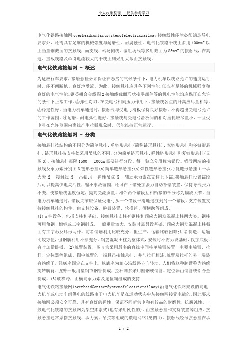
电气化铁路接触网overheadcontactsystemofelectricrailway接触线性能除必须满足导电要求外,还需具有足够的机械强度与耐磨性、耐腐蚀性。
电气化铁路干线上多用100mmZ以上当量铜截面的接触线,而支线、站场侧线、编组场线等多用截面为85mmZ的接触线,在高为适应行车要求,接触悬挂必须保证在恶劣的气候条件下,电力机车以线路允许的速度运行时,能不间断地、良好地受流。
为此,接触悬挂应具备下列性能:①应有足够的机械强度和良好的电气性能。
钢芯姐合金线图2接触线截面形状接零部件等的机电性能均应保证在允许的条件下正常工作。
②弹性均匀。
在受电弓相同压力作用下,接触线各点的升高应尽量相等。
③稳定性好。
当电力机车通过时,接触线与受电弓滑板保持良好接触,不得超出受电弓允许的工作范围。
④耐磨、耐电弧性能好。
接触线与受电弓滑板间的相对磨耗应尽量小,一旦受接触悬挂按结构的不同分为简单悬挂、单链形悬挂(简称链形悬挂)、双链形悬挂和多链形悬挂。
链形悬挂按支柱处采用吊弦的不同,分为简单链形悬挂、弹性链形悬挂和复链形悬挂(见图3)。
接触悬挂每隔1500一Z000m需要进行分段。
每一独立分段称为锚段。
锚段两端的接触线及承力索分别图3链形悬挂(a)简单链形悬挂;(b)弹性链形悬挂;(。
)复链形悬挂1一承力索;2一接触线;3一吊弦;4一弹性吊弦;5一辅助承力索在支柱上下锚。
接触悬挂设置锚段后可以提高供电灵活性,缩小事故范围,还可在下锚处加张力自动补偿装置,保持导线张力不变,使接触线弛度恒定,提高受流质量。
相邻两个锚段互相衔接的部分称为锚段关节。
当电力机车通过时,锚段关节应保证受电弓从一个锚段平滑地过渡到另一个锚段。
支持装置支持接触悬挂的构件,由支柱设备、腕臂装置、软横跨、硬横跨等组成。
(l)支柱设备,包括支柱和基础。
接触悬挂支柱有钢柱和预应力钢筋混凝土柱两大类。
钢柱可用角钢、槽钢或工字钢制成,一般重量较大,安装时需另设基础。
接触网毕业论文
电气铁路接触网施工技术摘要接触网、电力机车和牵引变电所并称为电气化铁道的“三大元件”,接触网是电气化铁道牵引供电系统中唯一的无备用供电设备而且裸露在外,其运营状态的好坏直接关系到电气化铁道的安全运行和经济效益,所以电气化铁道建设最重要的一部分就是接触网施工。
本文主要介绍新建电气化铁路的接触网施工技术,总结新线接触网施工的整体流程。
为了更好地阐述,本文还介绍了接触网的基本组成。
关键字:电气化铁道;接触网;施工技术AbstractContact net, electric locomotive and traction substation of electrified railways and known as the "three major elements", is the contact network of electrified railway traction power supply system there is no standby power supply equipment only and exposed to the outside, its operation state is directly related to the quality of electrified railway safe operation and economic benefit, so the most important part of the railway electrification construction is to contact network construction. This paper mainly introduces the construction technology of the new electric railway contact net,the overall process, summarize the construction of new lines of the contact net. In order to explain, this paper also introduces the basic component of contact system.【Key words】:Electrified railway;catenary;Construction technology.铁路是国民经济的大动脉,铁路电气化是建设中国特色的社会主义的重要环节之一。
电气工程及其自动化专业毕业论文外文翻译

电气工程及其自动化专业毕业论文外文翻译本科毕业设计(论文)中英文对照翻译院(系部)工程学院专业名称电气工程及其自动化年级班级 11级2班学生姓名蔡李良指导老师赵波Infrared Remote Control SystemAbstractRed outside data correspondence the technique be currently within the scope of world drive extensive usage of a kind of wireless conjunction technique, drive numerous hardware and software platform support. Red outside the transceiver product have cost low, small scaled turn, the baud rate be quick, point to point SSL, be free from electromagnetism thousand Raos etc. characteristics, can realization information at dissimilarity of the product fast, convenience, safely exchange and transmission, at short distance wireless deliver aspect to own very obvious of advantage. Along with red outside the data deliver a technique more and more mature, the cost descend, red outside the transceiver necessarily will get at the short distance communication realm more extensive of application.The purpo se that design this system is transmit customer’s operation information with infrared rays for transmit media, then demodulate original signal with receive circuit. It use coding chip to modulate signal and use decoding chip to demodulate signal. The coding chip is PT2262 and decoding chip is PT2272. Both chips are made in Taiwan. Main work principle is that we provide to input the information for the PT2262 with coding keyboard. The input information was coded by PT2262 and loading to high frequent loadwave whose frequent is 38 kHz, then modulate infrared transmit dioxide and radiate space outside when it attian enough power. The receive circuit receive the signal and demodulate original information. The original signal was decoded by PT2272, so as to driv e some circuit to accomplish customer’s operation demand.Keywords: Infrared dray;Code;Decoding;LM386;Red outside transceiver1 Introduction1.1 research the background and significanceInfrared Data Communication Technology is the world wide use of a wireless connection technology, by the many hardware and software platforms supported. Is a data through electrical pulses and infrared optical pulse switch between the wireless data transceiver technology.Infrared transceiver products with low cost, small, fast transmission rate, the point-to-point transmission security, not subject to electromagnetic interference and other characteristics that can be achieved between the different products, rapid, convenient and safe exchange and transmission, In short distance wireless transmission have a very distinct advantage.Infrared transceiver products in the portable product of a great role. At present, the world's 150 million piece of equipment used infrared technology in electronic products and industrial equipment. medical equipment and other fields widely used. For example, 95% of the notebook computers on the installation of infrared transceiver interface the majority of the cell phone is also the allocation of infrared transceiver interface. With the exchange of quantitative data, infrared datacommunications will enable cell phone data transmission more convenient. With infrared data transmission technology matures, perfect, low costs, Infrared Transceiver in short distance communications will be more widely applied.This chapter first describes the infrared transceiver IC design issues to the background and significance. then briefed the infrared data communications technology features and applications, and infrared transceiver product characteristics, domestic and international situation and development trend of the last under infrared remote transceiver system in practical application to establish a task of design orientation. 1.2 Infrared Remote Control Transceiver SystemInfrared remote control system is divided into single-channel and multi-channel remote control. Only a command signal transmission channel, called single-channel remote control system; with more than two instructions signal transmission channel known as a multi-channel remote control system. Relatively simple single-channel remote control, in general, only a launcher directive Key receivers and only one circuit implementation. While in the receiving circuit to add more stable memory circuits that can be activated commands to launch a number of key, so that the receiver circuit multi stable memory circuit repeatedly to change the state, to realize many of the functional control, But such a state of change is the order. If we are to achieve an arbitrary control, resort to the use of multi-channel remote control system. Multi-channel remote control can be realized by the object of arbitrary multi-function remote control. As for the choice of several routes and what control methods, according to the actual situation (such as object, operational requirements and cost accounting, etc.) to decide. General infrared remote transceiver system by infrared remote control transmitter signal coding, infrared remotecontrol signal receivers and decoders (or decoder chip MCU) and the external circuit consisting of three parts. Signal transmitter remote control code used to generate pulses of infrared emission-driven output infrared remote control signal, receiver completion of the remote control signal amplification and detection, plastic and demodulation encoding pulse. Infrared remote control coded pulse is going to obtain a continuous serial binary code, and for most of the infrared transceiver system, This serial code as micro-controller of the remote control input signals from the internal CPU completion of the remote control instruction decoder, on the other infrared remote control transceivers, the designers of electronic products, The internal micro-controller of the remote control decoder directive is not accessible. Therefore, people are using infrared encoder / decoder chip and microcontroller developed various generic infrared remote transceiver system, In various equipment infrared signals between the transceiver.Remote transceiver system generally transmitters and receivers is composed of two parts. Launchers from the general direction keys, coded instructions circuit modulation circuit, driving circuit, firing circuit of several parts. When pressed a key, the directive coding circuit, in the corresponding instructions encoded signal, the encoder signal to the carrier modulation, Driven by the power amplifier circuit after circuit fired from the field after firing instructions coded modulation signals. General receiver by the receiving circuit, the amplifier circuit, demodulation circuits, instruction decoder circuit, driving circuit, circuit implementation of several parts. Receiving Circuit will launch vehicles have been coded modulation signal receiving instructions from, and to enlarge evacuation demodulation circuit. Demodulation circuit will havethe coding modulation signal demodulation, namely, reduction of signal coding. The instruction decoder to the encoder signal decoding, Driven by the final circuit to drive the implementation of various instructions circuit to control the operation.1.3 infrared remote control transceiver product profilesCurrently infrared transceiver in accordance with the mode of transmission rate and can be divided into four categories : Serial mode, the highest rate of 115.2 Kbps; medium-speed model : the highest rate of 0.567 Mbps and 1.152Mbps; High-speed mode : The maximum rate of 16 Mbps.Also according to the size chip power consumption can be divided into low-power consumption and standard two categories, low-power type normally used 3 V power supply, transmission distance closer to about 0 - 30cm, which is commonly used standard 5V power supply, transmission distance away at least 1m above.Infrared communication technology in the development stage and there are several infrared communication standards, between different standards for infrared equipment can not infrared communication. To have all the infrared equipment to interoperability in 1993 by more than 20 large manufacturers initiated the establishment of an Infrared Data Association (IRDA) unified the infrared communication standards , which is currently widely used in infrared data communication protocols and standards, also known as the IRDA standard.Since 1993 IRDA since the establishment of the Infrared Data Association members have developed to more than 150. IRDA standards of the industry has been widely recognized and supported. Has beendeveloped with the infrared communications equipment have been as many as 100 species. IR module, installed capacity has reached 150 million sets. Although there is also a short distance wireless Bluetooth technology, But in infrared communication technology low cost and broad compatibility advantages, Infrared data communication in the future will still be a very long time inherent short-range wireless data communications fields play an important role.In various infrared transceiver products, although the transmission rate, transmission distance and other characteristics, But infrared transceiver products has been towards improving the transmission rate, increase the transmission distance and lower power consumption, expanding launch reception angle of development. In particular, as the technology development and maturity, the means of transmission is moving in the direction of point-to-multipoint. Therefore infrared remote control transceiver products have broader prospects for development.2 Infrared communication of knowledge2.1 infrared ray foundation knowledgeInfrared is actually a kind of electromagnetic wave. From the analysis of various natural component of the electromagnetic wave reflected spectrum is :-ray, x-ray, ultraviolet, visible, infrared, microwave and radio wave. From the viewpoint of form, and they did not seem to, but if the wavelength in descending order, and we will find him all theonl y visible light spectrum of the entire 0.38 μm - 0.76μm so long little area, and adjacent to the visible light and infrared (including the far infrared, mid-infrared and near infrared foreign) accounts for the spectrum of 0.76 μm - 1000μm of a major. Which micron wavelength range also includes UV, visible, near infrared, mid-infrared and far-infrared, microwave.From the above analysis shows that infrared is a very rich spectrum resources, it currently has in production, life, military, medical, and other aspects have been widely used, such as infrared heating, medical infrared, infrared communication, infrared camera, infrared remote control, and so on. Infrared remote control is the many applications of infrared part of the current household appliances widely used in TV remote control, VCR remote control, VCD remote control, high-fidelity audio remote control, are used infra-red remote control, It allows the control of these appliances have become very easy.Infrared lies between visible light and microwave a wave, it is with certain clinical characteristics of the wave. In the near-infrared, visible light and its adjacent, it is visible in certain characteristics, such as straight-line transmission, reflection, refraction, scattering, diffraction, can be certain objects and can be absorbed through the lens of their focusing. In the far-infrared region, owing to its neighboring microwave, it has some characteristics of microwave, If a strong penetrating power and can run through some opaque substances. Since in any object, natural profession, regardless of whether its own luminescence (referring to visible light), as long as the temperature is above absolute zero (-273 ° C), moment will be kept around to infrared radiation. Only higher temperature of objects strong infrared radiation, low-temperature objectsinfrared radiation weaker. Therefore infrared feature is the greatest common in nature, it is called thermal radiation called thermal radiation. Infrared cameras, infrared night market pyroelectric infrared detectors and some other missiles aiming at is the use of this characteristic of infrared work.Infrared and visible light compared to another characteristic of a variety of colors. As the longest wavelength of visible light is a wavelength of the shortest times (780 nm-380 nm), So is called an octave. And infrared wavelength is the longest shortest wavelength of a times, and the longest wavelength infrared is the shortest wavelength of 10 times, that is, 10 octave. Therefore, if visible light can be expressed as seven colors, infrared may performance 70 colors, showing the rich colors. Infrared smoke through the good performance, which is also one of its features.Because not visible to the infrared, it has little effect on the environment. By the wave infrared rays than the long wavelength radio waves, infrared remote control will not affect the nearby radio equipment. Another wavelength of less than 1.5μm near infrared light, transparent atmosphere in the visible light transmission characteristics much better than, because it close to the visible edge of the red light, linear transmission, reflection, refraction and absorption material and the physical characteristics very similar to visible light. Therefore, it can be used with similar visible focusing lens and other optical devices. Because infrared remote control is not as remote as the radio through the barrier to control the object's ability to control, so in the design of household appliances infra-red remote control, wireless remote control as unnecessary, each set (transmitters and receivers) have different frequency or remote coding (Otherwise, wall will control or interference with neighbors household appliances), all similar products in the infraredremote control, The same can control the frequency or coding, and no remote control signal "drop." This universal infrared remote control provides a great convenience. Infrared to visible light, is very subtle and confidentiality, therefore, the security, Alert and other security devices have been widely used. Infrared remote control is simple in structure and easy, low-cost, anti-interference capability, high reliability are a number of advantages, is a close-up remote control, especially in indoor remote control optimized manner.Infrared is not visible, people here are not aware of. Electronic technology is used infrared light emitting diode (also known as the IR emission diode) to generate infrared. Infrared remote control transceiver is using near-infrared transmission control instructions 0.76μm wavelength of ~ 1. 5μm. Near-infrared remote control as a light source, because there infrared light emitting diodes and infrared receiving device (photo diode. Transistor and PV) and the luminescence peak wavelength of light by the general 0.8μm ~ 0. 94μm. in the near-infrared band, both of the spectrum is the coincidence to a good match, access to higher transmission efficiency and higher reliability. Commonly used infrared diode, and its shape is similar LED light emitting diodes, Its basic circuit shown in figure 2 -2. The triode plans for the switch, when the base added a driving signal, Transistor saturated conduction infrared LED D is also Wizard Link, issued infrared (near infrared about 0.93 μm). D. The pressure drop of about 1.4 V and the current general for 10-20mA. To adapt to the working voltage of the D loop resistance often as a series of infrared diode current limit resistance.When the circuit diagram of the infrared emission control corresponding to the controlled device, the control of the distance and D is proportional to the transmitting power. In order to increase the distance of infrared control, infrared diode D should work on the pulse state that work is the lifeblood of current. Because pulse light (optical modulation) the effective transmission distance and pulse is proportional to the peak current, only maximize peak current Ip, will increase the infrared distance. Ip increase is a way to reduce the pulse duty cycle, that is compressed pulse width τ some TV infrared remote control, i ts infrared luminescence of the pulse duty cycle of about 1/4-1/3; Some electrical products infrared remote control, its duty cycle of 1 / 10. Decreasing pulse duty cycle also enable low-power infrared LED distance of the greatly increased. Common infrared light emitting diodes, power is divided into small power (1 mW - 10mW). Chinese power (20mW - 50mW) and power (50mW - 100mW more) three categories. Use different power infrared LED, the allocation should be driven by the corresponding power control. Figure 2 -2 by the reflected infrared light-emitting diodes to make produce optical modulation, Drivers only need to add the control of a certain frequency pulse voltage.Infrared transmitter and receiver in the way the two kinds of straight, and the second is reflective. Luminescence pointed straight pipe and tube receiver placed in a relatively controlled and fired on the two ends, a certain distance away from the middle; Reflective means luminescent tube and pipe parallel with the receiving peacetime, without always receiving tube light, luminescence only in possession of the infrared light reflected from encountered, the receiving tube received from the reflected infrared before work.2.2 infrared communication basic tenetsCommunication is the use of infrared wavelength of 900 nm-infrared waves from 1000 to serve as an information carrier, through infrared technology between the two close communication and confidentiality of information transmitted. Infrared communication system structure include : part launcher, channel, the receiver part.Launcher source letter issued after the binary signal from the high-frequency modulated infrared LED sent, receiving device regard the reception of high-frequency signals from the infrared receiver tube after receiving further demodulation photoelectric conversion of the original information of a mass communication lose way. Afterwards the former Information received after receiving part of the drive circuit connected to the expected completion of the various functions. To which the modulation coding style pulse width modulation (by changing the pulse width modulated signal PWM) and pulse modulation time (through change the pulse train interval time between the modulation signal PPM) two.(1) Launches : Currently there is a infrared wireless digital communications system sources of information including voice, data, images. Its methods of work for the launch of the receiver can be divided into different layout LOS way (Light-of-Sight , intracardiac way), diffuse (diffuse) mode. LOS way directional, it has good channel characteristics such advantages, but the existence of a "shadow" effect. difficult to achieve roaming function. Roaming means the main features of non-directional, and easy to implement roaming function, but its channel quality is better sometimes LOS way. Transmission of signals required fora few of (the sampling was quantified), the general need for baseband modulation, transmission, modulation, sometimes signal source coding, the above-driven signals from photoelectric converter complete optical signal transmission. Infrared wireless digital communications system and its scope of work-for-fired power distribution, the quality of the communication. While using various methods to improve optical transmitter power, the other using spatial diversity, holographic films and so on so diffuse light for the launch of space optical power evenly distributed.(2) Channel : infrared wireless digital communication channel refers to the transmitters and receivers in the space between. Due to natural light and artificial light sources such as light signals in the context of intervention, and the source - Electrical Equipment, The optical noise and disturbances, infrared wireless digital communications in some occasions, poor quality, At this point needed to channel coding. Infrared wireless communication system, the optical signal reflection, light scattering and background noise and interference effects, Infrared wireless digital channel presence multi-path interference and noise, This is to improve the quality and access for high-speed applications should be addressed. Infrared wireless digital communication channel often used by the major optical components, optical filter, condenser, their role is : plastic, filter, depending on the field transformation, the band division, the lens can be used as launch-ray focusing, the use of optical filters filter out stray light, the use of optical lenses to expand the field of view receiver, able to make use of optical components for the link frequency division multiplexing, etc.. Infrared wireless communication channel optical noise : the natural noise (sunlight) and anthropogenic interference (fluorescent lighting). canbe modulated by the transmission technology such as filters and adding to be addressed.(3) receivers : Channel optical signal from the optical receiver partially photoelectric conversion, In order to remove noise and intersymbol interference and other functions. Infrared wireless digital communications system receiver include optical receiver parts and follow-up sampling, filtering, judgment, quantity, balanced and decoding part. Infrared wireless optical receiver often used amplifier, and called for large-bandwidth, high gain, low noise and low noise, frequency response and channel impulse response matched. To be suppressed by low-frequency noise and human disturbance needs a band-pass filter. To obtain large optical receiver scope and instantaneous field of view, often using spherical optical lens.Wireless communications are a lot of ways, some using infrared communication with the following characteristics :• The high frequency, wave length, and fired the energy concentrated space propagation attenuation coefficient can ensure the effective signal transmission;• infr ared is the invisible light, strong confidentiality and use it as an information carrier. device when there is no visual pollution, it does no harm to the human body;• dissemination without limitation, and there is no question of frequency interference with radio-wave pattern, not on the spectrum resources to the relevant authorities for the application and registration, easy to implement;• has a good point, when the transmission equipment and infrared receiver ports line up straight, deviation of not more than about 15 degrees when infrared devices running the best effect;• through infrared or not bypassed and objects, data transmission, optical path can not be blocked;• currently produce and receive infrared signals in the technology is relatively mature, components small size, low cost production of simple, easy to produce and modulation advantages.2.3 infrared communication code based on the knowledgeUsually, infrared remote control transmitters will signal (pulse binary code) modulation at 38 KHz carrier, After buffer amplified sent to the infrared light-emitting diodes, infrared signals into firing away. Pulse binary code in a variety of formats. One of the most commonly used code is PWM (pulse width modulation code) and the PPM code (Pulse Code Modulation). The former said in a pulse width, pulse indicated 0. The latter pulse width, but the width of code-not the same, the codes represent a bit - and the digits represent narrow 0.Remote coding pulse signal (PPM code as an example) are usually guided by the code, the system code, the anti-code system, a feature code, functional anti-code signal components. Guide the code name for the initial code, by the width of 9 ms and the margin width of 4.5 ms to the low-level components (different remote control systems in the low-level high width of a certain distinction), remote coding used to mark the beginning of pulsed signals. System identification code is also called code, which used to indicate the type of remote control system, in order to distinguish other remote-control system, prevent the remote control system malfunction. Functional code is also called scripts, which represents the corresponding control functions, Receiver of the micro-controller functions under the numerical code to complete the variousfunctions operating. Anti-code system and function codes are anti-system code and the functional code against code Anti-code can be joined to the receiver synchronization transmission process leads to errors. In order to improve performance and reduce interference power consumption, The remote control will be coded pulse frequency of 38 KHz (for the cycle of 26.3 ms) of the carrier signal pulse reshuffle system (PAM), and then sent to the buffer amplified infrared LED, the remote control signal transmitter away.Address code and data codes are composed of different pulse width expressed that the two narrow pulse "0"; 2 pulse width "1"; a narrow pulse width and pulse expressed an "F" is the code addresses "vacant."Is the first part of a group a group of code, each code synchronization between separated. The plan is to enlarge the second half of a group code : a code from 12 AD (the address code plus data code For example, eight address code plus four data code), each with two AD-Pulse's : Pulse said the two "0"; 2 pulse width "1"; a narrow pulse width and pulse expressed an "F" is the code addresses "vacant."Realize fired at each fired at least four groups code, PT2272 only twice in a row to detect the same address code plus data code data will be the code "1" is driven The data should be output to drive margin and VT terminal for synchronous serial.红外遥控系统摘要目前红外数据通信技术是在世界范围内被广泛应用的一种无线连接技术,它也可以被许多软硬件平台所支持。
- 1、下载文档前请自行甄别文档内容的完整性,平台不提供额外的编辑、内容补充、找答案等附加服务。
- 2、"仅部分预览"的文档,不可在线预览部分如存在完整性等问题,可反馈申请退款(可完整预览的文档不适用该条件!)。
- 3、如文档侵犯您的权益,请联系客服反馈,我们会尽快为您处理(人工客服工作时间:9:00-18:30)。
电气化铁道技术接触网毕业论文中英文资料外文翻译文献附录1 外文资料翻译A1.1 译文铁路系统接触网中集电板碳合金的含量对其与接触线磨影响本文主要是对发生在接触网中接触线和集电板之间磨损情况的研究,它们之间的磨损由机械和电气两个方面引起。
这方面的研究对设施的维修成本和受电弓与接触线的工作寿命有着密切的关系。
由于接触网中维修机车和基础设施方面的重要性,在过去几十年世界上一直对这个问题十分重视。
为了探讨机械和电气两方面引起的接触线和滑板之间的磨损,在米兰设计并安装了一种新型的测试装置。
一系列的实验测试已经完成,其中涉及了多种材料的集电板和在不同转速与电流强度的接触条件。
研究中涉及到了3kV直流线路所需要的各种不同结构的集电板。
研究中发现集电板中的铜和碳合金的不同含量对滑板与接触线的磨损有着很大的影响。
前言高速铁路运输系统的发展意味着对电能需求的增加,但是从目前通过受电弓在架空线(接触网)获取电能的水平来看,就需要受电弓集电板具有较高的工作性能。
这个问题不仅仅由于高速列车的原因,而且与线路的容量和货运列车的长期运行有关。
意大利铁路系统决定把所有的铜材料的集电板换为Kasperowski型,随后又把碳合金用于集电板,这些在线路材料方面的改进都是对3kv直流线路的挑战。
当接触线上的电流达到1000A以上时就会由于产生的机械热加重受电弓集电板的损坏。
众所周知,接触线和受电弓集电板的磨损主要取决于以下几个因素:接触线材料的类型,运行条件(滑动速度接触力电流强度等)以及它们之间是否发出电火花和电弧等。
在Klapas et al.和Becker的的著作中,对以上提到的决定线路磨损程度的各种原因以及它们之间的相互影响都有说明。
基于简单方便起见,在集电板和接触线之间产生的磨损可以分为两种:一种是由于机械摩擦引起的磨损,另外一种是由于电火花引起的磨损,这两者相互作用并影响。
特别是越来越多的磨损不仅和线路的电流强度有关,而且和弓网之间的接触压力有关,同时和火花强度有关的磨损也随着接触压力的增大而加重。
再者,高电流在某些情况下可以通过所谓的当前润滑作用减少整体磨损。
并且速度的增加并不会总是造成磨损的加重,甚者在一些特殊的情形下由于热力条件增加引起的摩擦反而会减少磨损。
戴安娜和她的同事已经报道了有关这些内容的简要介绍。
本文将对以上提及到的几个方面通过测试装配实验进行详细研究。
人们考虑了几种集电板:所有的铜材型,包括外包铜的碳合金(Kasperowski型)和普通碳合金。
所有的集电板的设计都是基于3kv的直流线路。
值得一提的是它的滑动速度相当快(可达200km/h),并且电流强度也高于其他研究成果,直流电可达1000A。
以下对一些设备进行了试验并对结果进行了分析。
在试验中把磨损率和严格实验的程度相关连。
它们的关系基于耗散功率的假设,从而说明机械和电气两个方面的磨损的实质。
实验装配架概况这里要阐明的是试验装配架的主要特点。
该设备可以测试在时速达220km/h并通过1200A直流电或500A交流电的线路上受电弓的运行情况。
试验台的主要组成部分是一个直径4m的磁盘,它可以290rpm的最高速度绕垂直轴线旋转。
接触线安装在磁盘外圆周部位并朝向磁盘的径向方向,并且使滑动面水平的朝向受电弓的头部。
通过控制90千瓦直流电机由传送带带动磁盘转动。
受电弓被悬放在一个平台上面,并且它随一个三角波信号沿磁盘径向方向移动。
为了显示试验中对接触线的具体作用需要对磁盘的旋转进行同步测速。
试验中采用液压驱动的方式在接触线上产生平均压力。
为了在试验中模拟实际列车运行而产生的空气对流,要用管子使接触区的空气流动(常温下)。
接触线是由一组钢铝绞线组成。
试验架创建初始阶段进行的初步实验表明,如果接触线在磁盘上受到挤压时,那在集电板上将产生过大的垂直加速度(可达200m/s2)。
这种状况将使集电板产生异常的动态特性,这将给滑板带来严重的磨损损失,并在实际运行中出现严重的刮弓事故。
试验中的电路测试平台是由电容器馈电输出和一个绝缘栅双极晶体管构成三相全桥整流器组成的,从而由逆变器控制负载电流的输出电感。
将逆变器的开关频率适当提高,则可以降低电流中的谐波含量。
该逆变器可以仿真各种形式的电流(欧洲地区):直流电可达1kA,0.5kA—16.6Hz和0.5kA—50Hz三种。
为了平衡各有关量,采取了适当的测量措施。
通过放置在受电弓回锚的仪器可测量线路传输电流。
对接触滑动区和转动磁盘底部之间的压降的测量时,即假定的接触线和滑板之间的压降,可允许适当的线路损失。
等效的接触电阻可认为是两者之间的压降和电流强度之比。
在计算等效的接触电阻时,要考虑到两者实际接触面积的影响。
结论集电板和接触线材料的磨损情况已经在实验室通过仿真高速列车运行环境完成了具体的实验。
在线路传输1000A直流电并有时速达200 km/h列车运行的仿真工作环境条件下,对不同材料的集电板进行了测试。
经过详细研究弄清楚了滑板中碳合金的含量在其与接触线之间的磨损中所起的作用。
滑板的磨损与其单位长度的总耗散功率有关。
其中几中磨损的程度与碳合金和铜的含量有关,同时也发现以铜为主要材料的滑板由于摩擦力的原因而产生的磨损比较严重;以碳合金为主要材料的滑板则可以降低在电力线路上由于焦耳效应而产生的磨损,这是由于它的电阻比较高的缘故。
以铜为主要材料的集电板的磨损程度要比含碳合金的集电板高大约四倍。
这需要在一种有理想光滑面的接触线上检验,使得不造成在碳材料上的严重损失。
在滑动过度阶段中,碳滑板却要比铜的滑板受到更严重的磨损,而且在这个过程中还会在接触线和铜基之间造成擦痕。
当接触线单位长度的无功功率不一致时,在两区域就会产生不同的磨损率。
从这个方面来看以铜为基本材料的接触滑板具有高的磨损性能,而以碳为基本材料的接触滑板则属于低耐磨区。
A1.2 原文Effect of metallised carbon content of collector strip on the wear of contact wire–collector strip pair in railway systemsAmong the topics related to the interaction between the contact wire of the overhead line and the collector strip, the wear that takes place at the contact interface, depending on both electrical and mechanical quantities, represents an important aspect of maintenance costs, affecting the mean lifetime of collectors and contact line duration. Due to its importance in the global maintenance of both rolling stock and infrastructure, this topic deserved the attention of several regulations in the last decade.In order to investigate the effects of electro-mechanical wear on both contact wire and contact strip, a new test equipment has been designed and installed at Politecnico di Milano.A series of tests have been performed, involving different kinds of collector strip materials and contact conditions, tested at varying speeds and current intensities.This investigation concerned different collector strip configurations intended for 3 kV D.C. lines. The combination of different contents of copper and metallised carbon in the collector has been found to influence the wear rate of both collector strip and contact wire.key words: contact strip; contact wire; wear; friction; metallised carbonINTRODUCTIONThe development of higher speeds in railway transportation systems demands an increase of the required electrical power, and therefore of the level current to be collected by the pantograph from the overhead line (catenary), calling for higher performance from collector strips. This problem is not limited to high-speed trains but also concerns high-capacity lines and long-freight trains. The decision of Italian railways to move from all copper collector strips to the Kasperowski type, and subsequently to metallised carbon, for the 3 kV DC line is a real challenge for the materials proposed. The current is up to 1000 A for each collector, therefore exacerbating the thermo-mechanical problems on the collector. As known, the wear of collector and contact wire depends mainly on the following factors: type of materials at contact, operating conditions (sliding speed, contact force and electrical current intensity) and level of sparking and/or arching.The previously mentioned factors mutually interact in determining the level of wear, as shown in Klapas et al. and Becker et al., so that multidimensional maps can be defined. For the sake of convenience, wear at the collector–contact wire interface could be divided into mechanically and electrically caused contributions, even though it is clear that they are strongly correlated and mutually influencing. In particular, the increasing wear due to current intensity depends also on the level of contact force, since the sparking intensity at the contact,and the related wear, increases as contact force decreases. Moreover, high currents can, in some cases, decrease the overall wear through the so called ‘current lubrication’ effect. Furthermore, increasing the speed will not always result in increasing wear, and the changes in thermal conditions caused by the increased friction power will, under some circumstances, even reduce the wear. A brief summary concerning these topic has been already reported by Diana and colleagues.This paper presents the results of an investigation carried out by means of a test rig on some of the previously mentioned aspects. Several kinds of collector strips have been considered: all copper, metallised carbon with an external envelope of copper (Kasperowski type) and metallised carbon. All the strips are designed for 3 kV D.C. lines. It is worth mentioning that the sliding speeds are quite high (up to 200 km/h), and the currents are higher than in other published research, being up to 1000A D.C.Following a description of the test rig, the main experimental results are presented. A correlation between the wear of collector strips and contact wire with the operating conditions is reported. A correlation between wear rates and indexes of the test severity is also proposed. The relationship is based on the assumption of dependence from the dissipated power, and on the wear of both mechanical and electrical nature.TEST RIG OVERVIEWThe main features of the test rig, are herein recalled. The equipment enables testing of a collector to be performed at speeds up to 220 km/h under the passage of electrical current up to 1200 A D.C. and 500 A A.C. The main element of the test bench is a 4-m-diameter disc, rotating at a maximum speed of 290 rpm around a vertical axis.A contact wire is fitted on the outer circumference, with the s liding surface horizontally oriented towards the collector head of the pantograph, which is placed under the disc in a radial direction. The disc is moved by a controlled 90 kW A.C. motor through a transmission belt. The collector is elastically mounted on a suspension placed on a platform, which moves along the radial direction of the disc following a triangular wave signal. The period of the movement is synchronized with the test speed in order to reproduce the effect of the stagger on the real line. The mean contact force is applied by means of a hydraulic actuator.A pipe is used to blow air (at environment temperature) on the contact zone in order to reproduce the convective heat transfer due to the air flow around real moving vehicles.The contact wire is elastically suspended by means of a series of aluminium strands. Preliminary tests carried out during the set-up stage of the test rig put into evidence that the contact strip was subjected to excessive levels of vertical acceleration (up to 200 m/s2) if the contact wire is rigidly fixed on the disc. This condition leads to unrealistic dynamics of the contact strip, characterised by an unacceptable level of contact losses leading to more severe arching phenomena than in real operating conditions.The electric circuit of the test bench is made up of a three-phase full-bridge rectifier with capacitor output feeds and an Insulated Gate Bipolar Transistor (IGBT) inverter which controls the load current of the output inductor. The commutation frequency of the inverter is suitably high to ensure low-current harmonic content. The inverter allows the emulation of all the currents of the European catenaries: up to 1 kA D.C. current, 0.5 kA–16.6 Hz and 0.5 kA–50 Hz.A proper measurement set-up has been adopted in order to measure all relevant quantities. Transferred current is measured by means of an amperometer placed on the return cable from the collector. The voltage drop measured between the sliding contact and the base of the rotating disc is assumedas an indicator of the voltage drop between the contact wire and contact strip, and allows to estimate the percentage of contact loss occurrence. The equivalent contact resistance is estimated as the ratio between the voltage drop and the imposed current intensity. The equivalent contact resistance takes into account the effective contact resistance due to resistivity and the actual contact area together with the electrical resistance due toarching.CONCLUSIONSThe loss of collector strip and contact wire material has been evaluated in a laboratory test rig simulating the conditions of high-speed trains. Different types of collector strips were tested under working conditions of up to 200 km/h sliding speed and a current transfer of 1000 A D.C. The effect of the content of metallised carbon in the contact strip on the wear of both contact strips and contact wire was investigated.The wear of the contact strips shows a correlation with the total dissipated power divided by the longitudinal dimension of the contact strip. Several wear regions are found depending on the ratio between the content of copper and metallised carbon. This index also points out that Cu-based contact strips seem to suffer more from increasing the frictional power. C-based contact strips seems to be less sensitive to an increase of electrical power due to the Joule effect, correlated to the higher resistivity of the material.The wear of the Cu-based collector strips is approximately four times higher than the wear of the all-carbon contact strip. This behaviour requires an ideal smooth surface of the contact wire, which does not cause significant abrasion on the carbon. During a transition phase from an all-copper collector test to an all-carbon collector test, the all-carbon collector might undergo intense abrasive wear. This abrasion is caused by asperities on the wire surface formed when worn against the Cu-basedcontact strips.The wear rate of the contact wire reveals two distinct regions when plotted against the total dissipated work per unit length of the contact wire. The Cu-based contact strip constitute the high wear region. The low-wear region includes the C-based contact strips.附录2 相关装配图一﹑支柱装配图图1-1 直线中间支柱支持装置示意图图1-2 直线非绝缘转换柱(ZF2)装配示意图图1-3 曲线区段的绝缘转换支柱(QJ l)装配示意图图1-4 直线中心支柱(ZJ2)装配示意图二﹑定位装置装配图图3-8图2-1 定位装置形式。