秦皇岛酉威电机保护器YW-B说明书(新版)
WDB器说明书
WDB器说明书⼀、概述WDB电动机智能型电动机保护器,是⼀种提⾼电机运⾏安全和⾃动化管理⽔平的智能化仪器,核⼼采⽤美国MICROCHIP公司的微机控制器配低功耗集成电路开发⽽成的。
该保护器具有保护功能齐全,测量参数直观,反应灵敏,动作及时可靠,可以与上位机通讯构成远程监控于⼀体的⾼新技术产品。
⼴泛应⽤于⽯油、化⼯、煤炭、冶⾦、电⼒、钢铁、⽔泥、矿⼭、轻⼯、纺织等⾏业低压电动机保护及远程监控理想的产品。
⼆、特点1、采⽤微机技术和⾼性能低功耗电路,运算⾼速,性能稳定。
2、整机模块化结构,卡式电流传感器,体积⼩,安装⽅便。
也可分体安装,主体外形尺⼨按照国际仪表装置标准。
3、采⽤数字处理技术,测量精度⾼,线性度好,对故障判断速度快,精确可靠。
4、⾼清晰宽温带背光LCD显⽰,设置参数与测量及故障记录直观⽅便。
5、可以与计算机通讯构成远程监控于⼀体的电机保护⽹络。
6、⼀机多⽤,可取代电流表,电流变送器,热继电器,漏电继电器,电压表。
三、适⽤范围及使⽤条件1、380V AC,660V AC三相异步电动机,馈线电路保护。
2、保护器供电电压;220V AC,380V AC、50HZ。
3、外型结构:整体与分体两种形式,分体安装距离≤5⽶。
4、环境温度:-30℃~+65℃,相对湿度≤90%。
5、使⽤环境:⽆⾜以腐蚀⾦属和破坏绝缘性能⽓体的环境。
6、安装在⽆剧烈震动冲击,强磁场⼲扰场所和⾬雪侵袭的地⽅。
四、主要功能1、设定功能:额定电流、保护电流曲线、启动时间、三相不平衡、堵转倍数、漏电电流值、超⽋电压值、通讯地址、保护器上电电机⾃起动时间。
2、保护功能:过流、堵转、三相不平衡、短路、漏电、断相、超⽋压。
3、显⽰功能:A、B、C三相电流、漏电电流、⼯作电压、保护动作故障数据及故障记录、设置参数。
4、通讯功能:4~20MA标准电流输出信号,RS485串⾏通讯。
5、控制功能:通过RS485串⾏通讯与计算机可构成256台保护器常规保护控制⽹络。
电机保护器说明书

EOCR-3DD3DD与外接CT配合时的尺寸图示特点:•内装MCU(MCU)•三只完整的电流互感器•多种保护功能•数字电流表功能•脱扣(动作)原因显示•人工现场复位•电子遥控复位•自检功能•预报警设置功能•适应各种现场环境•电机起动延时(D-TIME),脱扣延时(O-TIME)可独立连续设定。
•失电安全自保(NO VOLT RELEASE)下载使用说明书:EOCR-3DD前调整面板图示:前面板DIP开关组(SW1-SW4):开关编号功能“OFF”关“ON”开SW1安全保护失效有效SW2逆相保护不能进行电机反转保护可以进行电机反转保护SW3动作特性定时限反时限SW4报警见相关介绍保护类型:可保护项目脱扣时间过电流O-TIME缺相4秒(05:1A,60:5A以上时动作)堵转D-TIME反相0.1秒(SW2拨至RPR位置)相间不平衡8秒故障显示:功能(项目)LED显示脱扣原因脱扣延时时间简单描述过电流A相出现5.5A的电流定时限:经过OT设置的时间后。
反时限:按时间--电流特性曲线动作。
负载电流大于预先设定的保护电流值。
逆相相序改变引起电机反转0.1秒内动作SW2置“ON”位缺相B相缺相4秒内动作相不平衡A相出现最小的不平衡电流2.1A8秒[((最大电流-最小相电流)÷最大相电流)]×100%>50%堵转C相出现最大的堵转电流9.5A经过DT设置的时间立即动作(仅用于定时限方式)负载电流大于预先设定的保护电流值的300%时。
报警输出:报警LED显示原因描述顺时针缓缓旋转报警点设置旋钮,显示窗显示“A”闪动,数字“85”,含义是:电机即时负载电流达到继电器预先设置保护电流值的85%。
报警设置值的范围是:50-100%或者关闭报警输出功能,当电机的(即时负载电流÷预先设置保护电流电流)×100>报警设置值时,显示窗显示“A”闪动,并从报警输出继电器(07,08)送出通-断信号。
XX-MM电机保护器说明书(V1.0)

1
XX-MM 电动机保护装置
1.2 产品功能 1.2.1 监测功能
常规信息采集 装置内对采集的各相电流数据进行滤波计算之后,可以通过装置面板的液 晶显示 A 相电流、B 相电流、C 相电流、零序电流、正序电流、负序电流、漏电 电流、过热百分比等的测量。 4~20mA 远传功能
装置内置光电隔离的 4~20mA 输出接口, 对应输出量可选择 Ia、 Ib、 Ic、 I0、 Ie、If、IL 物理量中的任意一项传送至远方控制中心,实现遥测功能。 本公司 4~20mA 的模拟量输出模块内置,无需外加任何附件,节省了安装空 间。 事件记录功能 装置记录的事件类型为保护动作事件。记录最近发生的 10 次事故信息,包 括事故的种类以及事故发生时的模拟量信息。掉电内容不丢失。
5.4.5 启停判据 .............................................. 19 5.4.6 出厂设置 .............................................. 20 5.4.7 修改密码 .............................................. 20 5.6 时间校正 ................................................... 21 5.7 事故清除 ................................................... 21 5.8 热量清除 ................................................... 21 5.9 事故记录 ................................................... 22 5.9.1 清楚事故 .............................................. 22 5.9.2 记录查看 .............................................. 22 第6章 第7章 7.1 7.2 7.3 7.4 第8章 技术参数 ................................................. 23 附录 ..................................................... 25 附录 A 典型接线图 ........................................ 25 附录 B Modbus 通讯规约(Vcom.1) ......................... 26 保护定值整定推荐表 ....................................... 28 初始密码表 ............................................... 29 服务承诺 ................................................. 30
电机保护设备说明书.pdf_1719234974.3339334
Degree of Protection Pollution Degree Connecting Capacity Auxiliary Circuit
Connecting Capacity
2
1SAZ700404F0001
45 mm 76.7 mm 53.5 mm
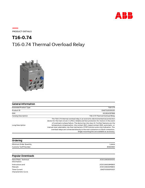
PThermal Overload Relay
General Information
Extended Product Type Product ID EAN Catalog Description
Long Description
Ordering
Certificates and Declarations (Document Number)
ABS Certificate
1SAA941001-0102
T16-0.74
BV Certificate CB Certificate CQC Certificate cUL Certificate Declaration of Conformity - CCC Declaration of Conformity - CE DNV GL Certificate EAC Certificate Environmental Information GL Certificate GOST Certificate Instructions and Manuals LR Certificate RINA Certificate RMRS Certificate RoHS Information Time-Current Characteristic Curve UL Certificate
Eaton 17.5 kV W-VACiMB 电源保护设备说明说明书

Q: Why was this breaker developed when Eaton already had a 15 kV VCP-TR breaker design used in the mining industry?A: The existing 15 kV VCP-TR breaker has been used for several years successfullyin the market. The newW-VAC i MB has several features that make it better suited for mining applications, such as the encapsulated pole units, 20,000 no-load mechanical operations rating and its compact design. This robust breaker has a 9 gauge,4 mm steel frame, with field-mountable accessories for mining applications.Q: What standards has this breaker been tested to?A: The 17.5 kV W-VAC i MB breaker has been tested tothe latest IEC 62271-100 and IEC 62271-1 standards. It meets/exceeds the electrical and mechanical endurance requirements of E2 and M2 in accordance with IEC 62271-100.Q:What are the ratings ofthis breaker?A: The 17.5 kV W-VAC i MB breaker is available in 25 kA symmetrical interruption rating with a continuous current rating of 1250A.Q: Does the breaker havecapacitive switching capabilities?A: Y es, the breaker has beentested for capacitive switching.It meets the standard cablecharging requirements and alsohas been tested for back-to-back(C1) applications at 400A.Q: How are the breakersecondary connections madefor control voltage?A: The W-VAC i MB has a sturdymanual secondary connection.The male and female connectionplugs are large and strong. Theconnection wires are coveredwith a tubular housing to protectagainst dripping water or anyother foreign particulates.Both the male and the femaleconnections are includedwith the breaker.Q: Is there a lifting deviceavailable for the breaker?A: No special lifting device isrequired. A simple, commonlyavailable sling/strap can beused. The breaker weight isapproximately 133 pounds.Q: What is the materialused in the molding of the17.5 kV W-VAC i MB breakerencapsulated pole unit?A: The 17.5 kV W-VAC i MBbreaker encapsulated poleunit is molded with epoxy,which is track-resistant.Q: Does the breaker have weargap indication?A: A principal feature of theEaton vacuum interrupters isthe large number of parallel arcsthat are created between thecontacts during breaking. Thearc energy is dispersed overthe contact surface area withvery little arc voltage and shortarc times, resulting in very lowarc energy. Therefore, contactwear in an Eaton interrupter isnegligible. This, in conjunctionwith encapsulating the vacuuminterrupter in epoxy, results incircuit breaker pole units thatare extremely durable. The solidinsulation technology protectsthe vacuum interrupter fromboth mechanical impact andforeign matter such as dust,humidity or other debris.The material is vibration- andshock-proof, and its durabilityis long-lasting. Based on theabove characteristics, weargap indication is not required.Q: Why is current chopping nota factor?A: Contact material improve-ments in the Eaton vacuuminterrupters over the yearsreduced the current chopfrom 21A to 3A.Q: How is the vacuum integrityof the vacuum interruptermonitored?A: Vacuum interrupters used inall W-VAC i MB circuit breakersare highly reliable interruptingelements. Satisfactoryperformance of these devices isdependent upon the integrity ofthe vacuum in the interrupter andthe internal dielectric strength.Both of these parameters can bereadily checked by a one-minuteAC high-potential test.Q: How are the vacuuminterrupters replacedwhen necessary?A: Except under extreme serviceconditions, replacement of thevacuum interrupter is not usuallyrequired during the life of theequipment. This is based on thedesign of the Eaton vacuuminterrupters. If the vacuuminterrupter does need to bereplaced, the complete breakerpole unit has to be replaced,because the vacuum interrupteris embedded in epoxy.Q: How many spare breakerauxiliary contacts are availablefor the customer to use?A: The 17.5 kV W-VAC i MBbreaker has 10A breakingcapability 6a and 7b spareauxiliary breaker contactsintegral to the breakeravailable for customer use.Q: What is the motorinrush factor?A: The inrush current is 400%of the running current.17.5 kV W-VAC i MB 25 kA 1250A breaker and associated components frequently asked questions 17.5Eaton is a registered trademark of Eaton Corporation.All other trademarks are property of their respective owners.Eaton Corporation Electrical Sector1111 Superior AvenueCleveland, OH 44114 USA © 2012 Eaton Corporation All Rights Reserved Printed in USAPublication No. MZ01306001E / Z12560August 2012Q: What is the breaker’s operational life?A: Our breaker is rated for 20,000 no-load mechanical operations.Q: Why is only one frame available for this breaker?A: The 17.5 kV W-VAC i MBbreaker size is small. Therefore, the one small-sized product can be used in place of several typical rating sizes.Q: How robust is the breaker chassis?A: The chassis is made of sturdy 9 gauge, 4 mm steel.Q: Has the design been seismically tested?A: This design has not been seismically tested, as this test should be done in complete switchgear, which is theresponsibility of the manufacturer of the complete switchgear.Q: Will other ratings be available in the future?A: At this time, these are the only ratings available for the 17.5 kV W-VAC i MB breaker. If other ratings are required, please contact your Eaton sales representative.Q: The breaker is only available at 17.5 kV voltage rating; can it be used at other voltages?A: This breaker can be used at any voltage between 0.5 and 17.5 kV , such as 1 kV , 5 kV , 12 kV , 15 kV and 17.5 kV . Q: The breaker is only available at 25 kA; can I use it at another interruption level?A: The breaker can interrupt at 0–25 kA, so it replaces typical ratings of 16, 20 and 25 kA all in one product.Q: The breaker is only available at 1250A thermal rating; can I use it at another thermal rating?A: The breaker can be used at 1–1250A ratings, so it replaces typical ratings of 630, 800 and 1250A all in one product.Q: What size busbars must be used for the 17.5 kV W-VAC i MB 25 kA 1250A breaker?A: The breaker was thermally tested in a closed steelenvironment with no venting. One 10 mm by 100 mm busbar per phase connection was used to obtain the 1250A thermal rating. If you would like to use the product with a different connection configuration, then the OEM must run a thermal test to confirm the rating, at a lower level with smaller busbars. Q: Can breakers be stacked? A: The OEM providing theswitchgear can test the product to prove it works in a stacked configuration.Q: Can the breaker be used in a cable-in/cable-out configuration?A: Y es, the breaker can be connected cable in and cable out. A terminal pad connection may be required to be made by the OEM making the switchgear connections. OEM testing of any cable connections is required.Other components Q: What secondary control voltage can be used on the motor?A: 24, 48, 60, 110, 125, 220 and 250 Vdc. Also 120, 220, 230 and 240 Vac.Q: What secondary control voltage can be used on the shunt opening release?A: 24, 48, 60, 110, 125, 220 and 250 Vdc. Also 120, 220, 230 and 240 Vac. The same options are available for shunt opening release number two as an option.Q: What secondary control voltage can be used on the shunt closing release?A: 24, 48, 60, 110, 125, 220 and 250 Vdc. Also 120, 220, 230 and 240 Vac.Q: What secondary control voltage can be used on the undervoltage release (UVR)?A: 24, 48, 60, 110, 125, 220 and 250 Vdc. Also 120, 220, 230 and 240 Vac.。
BFYK-11遥控智能电机综合保护器说明书

BFYK-11遥控智能电机综合保护器说明书BFYK-11遥控智能电机综合保护器说明书危险:严禁湿手操作保护器使用中严禁触摸导电部位维护保养时候,必须确保产品不带电严禁用短路的方法来测试产品注意:安装、维护和保养时,应由具有专业知识的人员操作产品的各项特性出厂时已整定使用中不得自行折装和随意调节使用前请确认产品的工作电压,额定电流,频率及特性是否符合工作要求:为防止相间短路,应对接线端裸露的导线或母线进行绝缘处理本产品只对负载端产生的漏电,过载,短路故障提供保护作用,但缺相时进出线均起到保护。
特别提醒:本保护器在线路出现故障跳闸后,请先检查线路,排除故障后再开机。
重新启动负载时先确保电机是静止状态,即保护器跳闸后让负载电机停止转动后再开启保护器,以免影响保护器的功能3000米遥控距离为理论距离,实际在2000米以内,同时距离的远近是跟使用的环境有关的,特别是有干扰和阻挡的地方距离也会缩短本保护器的所有功能都是经过制造商整定,任何人不得私自开启机壳,当遥控距离短或根本无法使用,有可能是遥控电量不足,此时可以根据遥控器的指示灯亮暗区分,如很暗说明遥控器要更换电池了,本遥控器使用的是9V重叠电池。
遥控使用的频率为315MHz,如果遥控距离变近或根本无法使用,也可能是因为信号干扰引起的,出现此情况可反应至工厂进行其它频率定制。
用途及适用范围1、我公司生产的智能电机综合保护器,主要集缺相、漏电、过载、短路、过欠压、定时、远距离遥控等多功能为一体。
用户可以根据负载电流(功率)大小调节,选择合适档位。
本产品既可以对运行中的380V50Hz的交流电机进行全方位的保护,也可以作为电机的不频繁启动开关,并且对线路中的变压器的跌落开关跳闸或总保险丝熔断而引起的多台电机缺相运行导致电机过流损坏的事故,能起到一定预防作用。
同时也适合潜水泵、风机、空压机的全方位控制保护。
本产品具有0~3000米(增益天线4000米)远距离遥控功能,特别适用于远距离鱼塘、田间抽水、山林灌溉。
电机保护器 PKZ2 型号0.6产品说明书

/binary/ver_techpapers/ver960de.pdf
27.03.2013
Eaton Industries GmbH
3/3
/de
© 11/2012 by Eaton Industries GmbH
feindrähtig mit Aderendhülse
ein- oder mehrdrähtig Anzugsdrehmoment Anschlussschrauben
Hauptleiter Hilfsleiter
Hauptstrombahnen
Bemessungsstoßspannungsfestigkeit
Motorstarter und „Special Purpose Ratings” für den Nordamerikanischen Markt
/binary/ver_techpapers/ver953de.pdf
Sammelschienenadapter für die rationelle Motorstartermontage - jetzt auch für Nordamerika -
Zusatzausrüstung 3 Normalhilfsschalter 5 Ausgelöstmelder 6 Arbeitsstromauslöser, Unterspannungsauslöser 7 Fernantriebe 8 Schaltantrieb, Hochleistungs‐Schaltantrieb, Strombegrenzer 9 Clipsplatte weitere Zusatzausrüstung Bemessungsgrenzkurzschlussausschaltvermögen Handbuch
Eaton Moeller PKZM0 电机保护电源保护器说明说明书

Eaton 199181Eaton Moeller® series PKZM0 Motor-protective circuit-breaker,0.25 kW, 0.63 - 1 A, Feed-side screw terminals/output-side push-interminalsSpécifications généralesEaton Moeller® series PKZM0 Motor-protective circuit-breaker199181401508197265475 mm94 mm45 mm0.249 kgIEC/EN 60947VDE 0660UL File No.: E36332IEC/EN 60947-4-1CSA File No.: 165628UL Category Control No.: NLRV ULCSA-C22.2 No. 60947-4-1-14 CSA Class No.: 3211-05CSAUL 60947-4-1CEULCSA PKZM0-1-SPI16Product Name Catalog NumberEANProduct Length/Depth Product Height Product Width Product Weight Certifications Model CodeTurn buttonPhase-failure sensitivity (according to IEC/EN 60947-4-1, VDE 0660 Part 102)Phase failure sensitiveMotor protectionThree-pole 100,000 operations100,000 OperationsDIN rail (top hat rail) mounting optionalCan be snapped on to IEC/EN 60715 top-hat rail with 7.5 or15 mm height.40 Operations/hIII3Motor protective circuit breakerFinger and back-of-hand proof, Protection against direct contact when actuated from front (EN 50274)6000 V AC25 g, Mechanical, according to IEC/EN 60068-2-27, Half-sinusoidal shock 10 msAlso motors with efficiency class IE3Branch circuit: Manual type E if used with terminal, or suitable for group installations, (UL/CSA)≤ 0.25 %/K, residual error for T > 40°-25 - 55 °C, Operating range-5 - 40 °C to IEC/EN 60947, VDE 0660Actuator type Features Functions Number of poles Lifespan, electricalLifespan, mechanicalMounting MethodMounting positionOperating frequencyOvervoltage categoryPollution degreeProduct categoryProtectionRated impulse withstand voltage (Uimp) Shock resistanceSuitable forTemperature compensationAltitude Terminal capacity (flexible with ferrule)Max. 2000 m-25 °C55 °C25 °C40 °C40 °C80 °CDamp heat, constant, to IEC 60068-2-78 Damp heat, cyclic, to IEC 60068-2-301 x (1 - 6) mm², Screw terminals2 x (1 - 6) mm², Screw terminals1 x (0.5 - 2.5) mm², Push-in terminals, ferrule to DIN 46228-12 x (0.5 - 2.5) mm², Push-in terminals, ferrule to DIN 46228-11 x (0.5 - 1.5) mm², Push-in terminals, ferrule to DIN 46228-42 x (0.5 - 1.5) mm², Push-in terminals, ferrule to DIN 46228-41 x (0.5 - 2.5) mm², Push-in terminals2 x (0.5 - 2.5) mm², Push-in terminals1 x (0.5 - 2.5) mm², Push-in terminals2 x (0.5 - 2.5) mm², Push-in terminals18 - 10, screw terminals20 - 14, Push-in terminals10 mm1.7 Nm, Screw terminals, Main cable50 Hz 60 Hz 1 A0.12 kW 0.25 kW 690 V 690 V 1 A 50 kA, 600 Y/347 V, SCCR (UL/CSA) 65 kA, 240 V, SCCR (UL/CSA)65 kA, 480 Y/277 V, SCCR (UL/CSA)± 20% tolerance, Trip blocksBasic device fixed 15.5 x Iu, Trip Blocks 15.5 A, Irm, Setting range max.Push-in terminals on output side Screw terminals on feed sideAmbient operating temperature - min Ambient operating temperature - maxAmbient operating temperature (enclosed) - min Ambient operating temperature (enclosed) - max Ambient storage temperature - minAmbient storage temperature - maxClimatic proofing Terminal capacity (flexible)Terminal capacity (solid)Terminal capacity (solid/stranded AWG) Stripping length (main cable) Tightening torqueRated frequency - minRated frequency - maxRated operational current (Ie)Rated operational power at AC-3, 220/230 V, 50 Hz Rated operational power at AC-3, 380/400 V, 50 Hz Rated operational voltage (Ue) - minRated operational voltage (Ue) - maxRated uninterrupted current (Iu)Short-circuit current rating (type E)Short-circuit releaseConnectionNumber of auxiliary contacts (change-over contacts)0 1 A1 AOverload trigger: tripping class 10 A5.33 W0 W0 W0 WMeets the product standard's requirements.Meets the product standard's requirements.Meets the product standard's requirements.Meets the product standard's requirements.Meets the product standard's requirements.Does not apply, since the entire switchgear needs to be evaluated.Does not apply, since the entire switchgear needs to be evaluated.Meets the product standard's requirements.DA-DC-00004918.pdfDA-DC-00004888.pdfETN.PKZM0-1-SPI16.edzIL03407011Zpkzm0_s16_pi.dwgpkzm0_s16_pi.stpeaton-manual-motor-starters-pkzm-pkzm0-dimensions-002.eps 121X042121X002eaton-manual-motor-starters-pkz-dimensions.epseaton-manual-motor-starters-pkz-dimensions-002.epsNumber of auxiliary contacts (normally closed contacts)Number of auxiliary contacts (normally open contacts)Overload release current setting - minOverload release current setting - maxTripping characteristicEquipment heat dissipation, current-dependent PvidHeat dissipation capacity PdissHeat dissipation per pole, current-dependent PvidStatic heat dissipation, non-current-dependent Pvs10.2.2 Corrosion resistance10.2.3.1 Verification of thermal stability of enclosures10.2.3.2 Verification of resistance of insulating materials to normal heat10.2.3.3 Resist. of insul. mat. to abnormal heat/fire by internal elect. effects10.2.4 Resistance to ultra-violet (UV) radiation10.2.5 Lifting10.2.6 Mechanical impact10.2.7 Inscriptions Declarations of conformity eCAD model Instructions d'installation mCAD modelSchémas10.3 Degree of protection of assembliesDoes not apply, since the entire switchgear needs to be evaluated.10.4 Clearances and creepage distancesMeets the product standard's requirements.10.5 Protection against electric shockDoes not apply, since the entire switchgear needs to be evaluated.10.6 Incorporation of switching devices and componentsDoes not apply, since the entire switchgear needs to be evaluated.10.7 Internal electrical circuits and connectionsIs the panel builder's responsibility.10.8 Connections for external conductorsIs the panel builder's responsibility.10.9.2 Power-frequency electric strengthIs the panel builder's responsibility.10.9.3 Impulse withstand voltageIs the panel builder's responsibility.10.9.4 Testing of enclosures made of insulating materialIs the panel builder's responsibility.10.10 Temperature riseThe panel builder is responsible for the temperature rise calculation. Eaton will provide heat dissipation data for the devices.10.11 Short-circuit ratingIs the panel builder's responsibility. The specifications for the switchgear must be observed.10.12 Electromagnetic compatibilityIs the panel builder's responsibility. The specifications for the switchgear must be observed.10.13 Mechanical functionThe device meets the requirements, provided the information in the instruction leaflet (IL) is observed.Eaton Corporation plc Eaton House30 Pembroke Road Dublin 4, Ireland © 2023 Eaton. Tous droits réservés. Eaton is a registered trademark.All other trademarks areproperty of their respectiveowners./socialmedia。
YW-300B说明书
1:机床的用途及特点第1页1.1用途:YW—300B型电流互感器环形数控绕线机是本公司引进国内外先进技术的基础上,根据国内互感器行业新工艺要求,自行开发研制的高精度新型电流互感器专用环形绕线机。
该机用于绕制各种环形电流互感器线圈,特别适用于小批量、多品种线圈绕制。
本产品自投放市场以来经多方验证,具有绕线精度高、使用范围宽、操作简便、调整方便且通用性强等优点,其稳定、可靠、高效的性能得到用户的一致好评,是国内最先进的数控绕线设备。
1.2特点:(1)该机采用国际上最先进的PLC可编程主控系统,通过触摸屏设定程序,极大的增强了整机运行的可靠性。
〔2〕电器控制部分全部为模块设计,降低了维护成本,主传动采用变頻控制调速方式,保持了传动链短、启动力矩大、调节范围宽、节能降噪等优点。
〔3〕绕线分步直接采用步进电机与高精度减速机控制,从而解决了传统机械齿轮传动所带来的误差分步不均匀,是环形绕线机的一次突破,并且可实现自0.01mm起至连续步进的无极调速,分步精度高、扭矩大。
由于采取了PLC可编程技术,使机床具备自动储线、自动计数、自动停车、停车记存等功能,及大大的减化了操作。
第2页(4)该机设计了单线、双线、或多线多层并绕,从而彻底解决了精密电流互感器多线环形绕组的绕制工艺难题,在绕制过程中承受的拉力均匀且可根据不同的线径随机调节,避免了电磁线的损伤,从而比人工绕制更为节省漆包线,也缩小了互感器外形尺寸,使产品的整体成本相应降低,也提高了互感器的综合电气性能,及大的提高了经济效益。
2:安装及注意事项第3页2.1安装:(1)机床安装的室内温度不应超过+30~0摄氏度范围,机床用机脚螺栓调整,使其处于水平状态并不得晃动。
(2)安装场所内不得有严重影响机床的腐蚀气体,化学尘积,灰尘污垢及其它易燃,易爆物体。
(3)请勿让本机暴露在雨中或处于潮湿环境中。
2.2注意事项:(1)本机要求输入电压为220V±10%,在使用本设备前,应先用接地线,要求接地线电阻≤10欧姆。
WDB-06微机电动机保护装置说明书
WDB-06 系列微机电动机保护说明
路的遥信输入。 ● 为满足变电站自动化系统的要求, WDB-06C 装置具有本电动机的所有遥测量、 遥信量、 电度脉冲量和开关的遥控等测量和控制功能。 ● WDB-06C 装置所有的保护功能压板及定值切换均为“软”方式,即通过遥控的方式实 现保护功能的投/退及保护定值区的切换,真正满足变电站“无人值班”的要求。 ● 具有远方进行保护定值管理功能,包括:定值的显示、修改、固化等。方便继电保护人 员对保护的远方管理,并具有可靠性高的特点。 ● 装置带有一个高速数据通讯网络(CAN,即 Controller Area Network),CAN 网络是一种 专门的现场控制网络, 开放性强, 广泛应用于工业控制场合, 国际上众多芯片制造厂(如: PHILIPS,SIEMENS,MOTOROLA,TI)等均生产 CAN 网络的相关产品,国际和国内 的保护生产厂也广泛采用 CAN 网络作为站内的通讯网络(如 ABB 等),有关 CAN 网络 的特点及应用参见《WBX-35 变电站自动化系统产品介绍及目录》 。 ● 装置人机界面友好,采用宽温型 LCD 显示,菜单显示清晰直观,键盘简单明了,使用 方便,另外,可通过打印接口盒实现站内所有装置的集中打印,对继电保护人员的试验 和管理提供了方便。 ● ● 采用通用化,模块化设计,装置的主要插件,如:CPU 插件、MMI 板均为通用插件。 本装置采用标准 19/3 英寸的 6U 机箱,结构紧凑,体积较小,适于安装在开关柜上。
WDB电机保护器说明书
feelings surve y, by l ooki ng up public sentiment s to find probl ems. Pr oblem s will increase its spe cial s upervi sion, set up accounts , hol d on to it. We s hould cons cienti ously im plement the leadi ng contracting matters, s ecured, had an a nsw er to everythi ng, the n settles rate of 100 %. Have an im pact on some of the outsta ndi ng iss ues, supervisi on departments a nd i nformation com ponents toget her, play the s upervisory r ole of the news medi a to prom ote problem solving. I nvestee 3. i nsist on a daily run, around t he pra ctice of truth catching efficie ncy, focus s pecification. To give full play to the party Office around connecti ng, coor dinati ng internal a nd exter nal features, conta ct, rally at all levels, to motivate every a spe ct, adhere to the truth, stre ngthe ning sta ndar dize d management to a chi eve cohere nt, efficient and effective functioning of the daily w ork of the Party Committee. Is pr oce ss ing messages s hould strive to streamline, standardize a nd qualit y.
WGB-53(C)WGB-54(C)WGB-55(C)说明书

WGB-53(C)WGB-54(C)WGB-55(C)说明书1.保护对象说明本装置为微机综合保护装置,根据软件的不同配置可实现对线路、电动机、电容器及厂用变的保护,装置在出厂时默认设置为线路保护,在实际使用时请用户务必将保护对象设置的与实际相符;具体设置方法如下:2.整定说明假设用户要对‘过流I段’定值按如下要求整定:将本保护投入,电流定值设置为21.4A,延时设置为0.2 s,可参照如下流程进行:3.控制回路异常说明在使用时因控制回路接线不当本装置可能会有‘控制回路异常’的告警提示,如果出现如上情况可按照如下方式进行处理:进入装置“查看”菜单下的“开关量”子菜单,查看本菜单下的TW(跳位)和HW (合位)的状态,正常情况下断路器在跳闸状态时TW为1、HW 为0,断路器在合闸状态时TW为0、HW为1,如与上述情况不符可判断为控制回路接线错误,请仔细参照本说明书的第6节“产品接线说明”和WGB-53(C),WGB-54(C),WGB-55(C)控制回路接线示意排图’进行查修正;4.调试说明部分用户在对本装置实验时由于设置、接线或操作不当可能出现如下状况:例如预对‘过流II段’进行动作试验,对装置施加了电流但保护却不动作,如出现上述情况应该为用户原因,可按如下方法排查:A.检查‘过流II段’保护功能是否投入、电流定值及动作延时是否妥当,检查方法如下:在“查看”菜单下的“定值”子菜单选择当前使用的定值区进入,按“↓”键翻到‘过流II段’的相关定值上,确认压板已经投入并且定值合理,否则需到‘整定’菜单下对‘过流II段’定值进行重新整定;B.检查是否对保护装置正确的施加了电流,主要包括如下方面:◇用户使用的电流输出设备是否工作正常;◇用户对装置交流回路的接线是否正确,施加的电流回路是否正确;◇用户施加的电流是否已经大于了‘过流II段’的电流定值并且已经等待了本保护规定的动作延时;◇查看本保护装置实际采集到的动作电流是否与用户施加的电流相符,查看方法:在装置的‘主信息屏’或者进入“查看”菜单下的“模拟量”子菜单即可看到装置实际的采样电流。
WDB系列微机监控电机保护器安装使用说明书(精)
WDB系列微机监控电机保护器使用及设置说明WDB系列微机监控电机保护器是国内低压电机保护器的最新产品,参数测量精度高,保护功能齐全,参数显示直观,我厂在同步电动机及异步电动机的辅助油泵上广泛应用,为规范保护定值的设定,避免保护装置误动作,便于装置的维护和管理,特制定本说明,望班组认真学习,遵照执行。
一、型号规格1、型号◆WDB—A型微机监控电机保护器,该保护器具有对电机进行检测、控制、显示及保护等功能。
◆WDB—B型型微机监控电机保护器,该保护器由主机与显示器组成,主机与显示器设定及显示各种参数,适用于对远距离电机进行检测、控制,主机与显示器之间距离≤1200米。
◆WDB—C型型微机监控电机保护器,该保护器增加了RS485串行数字接口,一台PC机可对256台保护器各种参数进行检测、控制和显示。
2、规格选择见表33.使用原则:①压缩机辅机②系统单机组③系统内双机组切换可能造成系统波动、减量④55KW以上电机(没有安装GL过流继电器二、主要功能1、保护功能:过流、堵转、三相电流不平衡、断相、过压、欠压、漏电、短路等保护。
2、设定功能:可现场设定额定电流值,启动时间、过压值、欠压值、过流动作时间、堵转电流对额定电流的倍数及特殊规定的自启动时间、漏电电流值及地址号。
3、显示功能:通电时显示电压值,检测状态时循环显示A、B、C三相电流值,保护状态时过流、过压、欠压值记忆显示,故障各类别字符提示显示,设置状态时显示各故障字符及设定值。
4、通信功能:通过串行数字接口,实现信息传送,一台PC机可接256台保护器,并可对每台电机进行参数设定、启动操作,便于自动化管理。
三、主要技术指标1、测量范围:电流0—9999A、电压AC150—AC500V。
2、测量精度:1.5级。
3、保护触点容量:AC220V/5A、AC380V/3A,电寿命≥105次。
4、启动时间整定范围:1—99S,在启动时间内,只对断相、过压、欠压、漏电、短路及三相电流不平衡进行保护。
新维-AMDS B 系列电动机保护器使用手册

第十七章 AMDS-□/B系列电动机保护器17.1、AMDS-□/B 系列电动机保护器AMDS-□/B 0 □ □1: 1常开、常闭继电器触点(AC 250V/10A(阻性负载)、DC 30V/10A);2: 2常开、常闭继电器触点(AC 220V/5A(阻性负载)、DC 30V/5A);0:接地、短路、缺相、堵转、电流不平衡、过载;1:接地、短路、缺相、堵转、电流不平衡、过载、零序;无通讯接口、无4-20mA输出、无运行状态输出;4 位LED显示3相及零序电流、故障代码、保护参数;保护器额定电流(A),是 0.5、1、2、5、10、20、50、100、150、200 之一;AMDS-□/B 系列保护器主单元 AMDS-□/B 系列电流检测单元及电缆主要特点:单片机为核心,数字设定、数字显示,保护功能完备、保护性能可靠。
按键设置保护参数,4位LED数码管显示三相及零序电流、故障代码、保护参数;主单元小体积柜内导轨安装;基本保护功能:接地、短路、缺相、堵转、电流不平衡、过载;可选保护功能:零序;适用范围:额定电压不高于1140V,频率为50Hz、60Hz的三相交流电动机;工作电压:AC 85V — 265V、DC 85V — 265V;功率消耗:小于 2W;采集精度:1.0;环境温度:- 20℃ — 50℃;连接电缆:连接主单元与电流检测单元,6×0.3mm²×2.2 m双绞屏蔽电缆。
17.2、AMDS-□/B 系列电动机保护器技术数据(型号省略了AMDS-□/B0□□中的/B0□□)电动机保护器型号 AMDS-0.5 AMDS-1 AMDS-2AMDS-5AMDS-10AMDS-20AMDS-50 AMDS-100 AMDS-150AMDS-200最大设定电流(A) 0.55 1.1 2.3 5.5 11 23 55 110 165 220 最小设定电流(A) 0.1 0.2 0.4 1 2 4 10 20 30 40 电动机最大功率(KW) 0.22 0.4 1.1 2.2 4 11 22 45 75 110 电动机最小功率(KW) 0.055 0.11 0.22 0.55 1.1 2.2 5.5 11 18.5 22 电动机电源穿线孔Φ(mm)20 20 20 20 20 20 20 20 30 30 注:表中电动机的额定电压为380V,电动机因型号、极数的不同,相同功率的额定电流会有不同,选用电动机保护器时应以电动机工作电流值为准。
Klixon 16HM 三相电机保护设备说明说明书

34HM | MOTOR PROTECTORSHermetically Sealed On-Winding, 3-Phase SPECIFICATIONSFProduct DescriptionLine Break Operation• Protect WYE (Star) wound 3-phase motors from 1 to 6HP. Used in refrigeration compressors, submersible pumps and other restrictive environments.shape allows for close coupling to motor windings.• Hermetic reliability designed for leakage rates less than 1 x 10⁻⁹ cc per second of air with 1 atmosphere pressure differential.• Klixon® snap-action discs assure positive make and break action and controlled temperature differential.• Designed for low and high side pressure applications.Klixon® 16HM motor protectors are line break automatic reset controls which are wired in series with the motor windings. These protectors are designed to track winding temperatures and to respond to changes in line current. When properly applied, the 16HM can provide protection againstmotor overheating under the following conditions:This protector is designed to protect 3-phase refrigeration and air conditioning compressor motors from excessive winding temperature; however, device to be installed directly on motor windings for closely coupled temperature monitoring, thus enhancing over-temperature protection against loss of refrigeration charge, low voltage locked rotor, and secondary single-phasing (loss of phase). The 34HM is designed to reduce installation costs by replacing pilot control systems with a simple, economical, compact device.The basic element of the 34HM is the famous Klixon® Snap ActMaximum Recommended Locked Rotor CurrentCurrent ratings are based on life test data which has demonstrated high reliability at 5K cycles (standard series) and 2K cycles (high capacity series) at 0.7 ower factor on Sensata life test boards. These capacities are intended as a guide for application work.Standard Operating TemperaturesDIAGRAMS34HM Hermetic Motor ProtectorElectrical SchematicWUnitInsmmW0.67017.0H1.14029.0P10.55614.1L1.17029.7P20.0892.3P30.2506.4A0.58514.9B1.08027.4Standard / High Capacity DeviceProtector ShellCompressorMotorWindings34HM CODE SYSTEMQuick ConnectsWire LeadsSleeves, etc.When making an inquiry on Klixon® hermetically sealed motor protectors, be certain to specify the entire part number for your application,AGENCY APPROVALS & CERTIFICATIONSPage 5CONTACT USSensata Technologies, Inc. (“Sensata”) data sheets are solely intended to assist designers (“Buyers”) who are developing systems thatincorporate Sensata products (also referred to herein as “components”). Buyer understands and agrees that Buyer remains responsiblefor using its independent analysis, evaluation and judgment in designing Buyer’s systems and products. Sensata data sheets havebeen created using standard laboratory conditions and engineering practices. Sensata has not conducted any testing other than thatspecifically described in the published documentation for a particular data sheet. Sensata may make corrections, enhancements,improvements and other changes to its data sheets or components without notice.Buyers are authorized to use Sensata data sheets with the Sensata component(s) identified in each particular data sheet. HOWEVER, NOOTHER LICENSE, EXPRESS OR IMPLIED, BY ESTOPPEL OR OTHERWISE TO ANY OTHER SENSATA INTELLECTUAL PROPERTY RIGHT, ANDNO LICENSE TO ANY THIRD PARTY TECHNOLOGY OR INTELLECTUAL PROPERTY RIGHT, IS GRANTED HEREIN. SENSATA DATA SHEETSARE PROVIDED “AS IS”. SENSATA MAKES NO WARRANTIES OR REPRESENTATIONS WITH REGARD TO THE DATA SHEETS OR USEOF THE DATA SHEETS, EXPRESS, IMPLIED OR STATUTORY, INCLUDING ACCURACY OR COMPLETENESS. SENSATA DISCLAIMSANY WARRANTY OF TITLE AND ANY IMPLIED WARRANTIES OF MERCHANTABILITY, FITNESS FOR A PARTICULAR PURPOSE, QUIETENJOYMENT, QUIET POSSESSION, AND NON-INFRINGEMENT OF ANY THIRD PARTY INTELLECTUAL PROPERTY RIGHTS WITH REGARDTO SENSATA DATA SHEETS OR USE THEREOF.All products are sold subject to Sensata’s terms and conditions of sale supplied at SENSATA ASSUMES NO LIABILITYFOR APPLICATIONS ASSISTANCE OR THE DESIGN OF BUYERS’ PRODUCTS. BUYER ACKNOWLEDGES AND AGREES THAT IT IS SOLELYRESPONSIBLE FOR COMPLIANCE WITH ALL LEGAL, REGULATORY AND SAFETY-RELATED REQUIREMENTS CONCERNING ITS PRODUCTS,AND ANY USE OF SENSATA COMPONENTS IN ITS APPLICATIONS, NOTWITHSTANDING ANY APPLICATIONS-RELATED INFORMATIONAmericas+1 (508) 236-2551electrical-protection-sales@sensata.comEurope, Middle East & Africa+1 (760) 597 7042*****************************************************.comChina +86 (21)2306 1651Japan +81 (45)277 7104Korea +82 (53) 644 9685India +91 (40)4033 9611Rest of Asia +886 (2) 27602006ext 2808。
XW-PLB 型发电机综合保护器 说明书

一、概述在传统的电站保护系统中,对于发电机的过流过压保护,多使用继电器式保护装置。
这类装置普遍存在精度不高,稳定性可靠性差,安装繁琐的缺点。
XW-PLB型发电机综合保护器是针对继电器式保护存在问题而专门设计的智能型控制保护装置。
它以八位微处理器为核心采用精确控制算法使装置具有优良的控制性能与控制精度。
本装置具有过载、过流、短路反时限电流保护以及过压、欠压、过速、欠速、飞车保护于一体。
可完全取代传统多个继电器的保护模式,简化了安装过程并且提高了可靠性。
装置能实时显示发电机电压、电流、频率值,易于观察与操作。
使用非常方便可适用于中小型电站与老电站的改造。
能极大地提高发电机保护的可靠性和安全性,同时对于提高电站的自动化水平也具有积极意义。
二、技术指标1、适用范围:各类中、小型高压和低压发电机组2、输入信号:(1)PT电压:①.标称100V发电机PT电压互感器电压②.标称230V发电机相电压③.标称400V发电机线电压(2)三相电流:标称5A发电机三相CT(电流互感器)电流信号3、输出信号:继电器开关信号(常开方式)继电器触点容量:交流220V/5A,380V/2A直流110V/0.8A220V/0.2A①.故障输出用于分断并网开关②.飞车保护输出用于控制调速器减速或水旁路4、电压测量精度:1.0级5、电流测量精度:1.0级6、频率测量精度:0.5级7.工作电源交流150VAC~285VAC直流100VDC-300VDC8.功耗小于6W9.工作环境环境温度-5°~+45°相对湿度不大于90%海拔2000米以下地区10.安装尺寸长112mm×宽112mm×深108mm11.开孔尺寸(见图7)114mm×114mm三、主要功能1、过压保护系统运行中当发电机电压连续高于设定过压保护值一定时间(此时间可设定)时,保护器判为过压故障,保护器不管并网以否都发出常规‘跳闸’命令(常规‘跳闸’命令即:‘故障’继电器与‘飞车’继电器同时动作,10秒后若测出发电机频率≤52HZ,则解除继电器的动作)用于‘跳闸’(并网时)和调速器减速,同时发出常规告警信号(断续蜂鸣告警声、故障指示灯亮)数码显示自动切到电压值显示状态,实时显示此时的电压值,同时电压指示灯闪烁。
- 1、下载文档前请自行甄别文档内容的完整性,平台不提供额外的编辑、内容补充、找答案等附加服务。
- 2、"仅部分预览"的文档,不可在线预览部分如存在完整性等问题,可反馈申请退款(可完整预览的文档不适用该条件!)。
- 3、如文档侵犯您的权益,请联系客服反馈,我们会尽快为您处理(人工客服工作时间:9:00-18:30)。
传导发射
1EC61000-4-5
Level 3:1.2 ×50 滋s,4KV (0° , 90°,180°,270°)
Enission CISPR11
ClassA(Conducted and radiated)
故障代码
显示
描述
注释
过流跳闸
预定的时间内
欠流跳闸
3 秒内
缺相跳闸
不平衡率超过 70%时 1.5 秒内
OFF
OFF/On
逆相保护
OFF
OFF,30—90%
欠电流保护
OFF
OFF,0.03, 0.05/0.1—3A
ZCT 方式的接地保护
OFF
OFF,20-500% 矢量方式的接地保护(FLCmin) OFF
0.05,0.1-1.0
接地故障动作时间(秒)
On/OFF
启动时接地动作延时
OFF
OFF,500-1000%
日期,同时在断电的情况下通过 S/W 设置好电流范围。
3援快速设置 1、同时按下 Up 和 IEnter 键,保护器显示“UPLD”,同时保护器的设置 上传到至显示器中。 2、把设置好的显示器插入没有设置的保护器中,然后按 Test 键进入 测试模式。 3、同时按下 Down 和 Enter,保护器显示“TEST”,同时显示器中的参 数自动下载到保护器中。 4、按 Test 键返回到正常模式。
说明 电气复位 自动复位(分) 运行时间 运行时间设定(小时] 年/月/日/时:分 总的运行时间 20mA 对应的电流值 通讯地址 通讯速度
SWAP
出厂值 On OFF
420 型 485 型
电机与保护器匹配
电流选择 S/W 0.5—10A 5—100A
0.5-10A
穿绕次数 4 2 1 1 1 1 1 1 1 1 1
故障记录次数 5 次
通讯方式 MODBUS/4-20mA
电机频率 20—200Hz,可用于变频器回路
复位方式
自动方式:1~20 分钟 手动/电气(ON/OFF 选择)
安装方式 35mm 轨道和控制柜面板
精 度 电流:±5%;时间:±5%;4-20mA:±5%
辅助触点 使用环境 绝缘电阻 耐压强度 静电放电
3-SPST 3A/250VAC 阻性负载
工作温度 存储温度 湿度
-10--55℃ -20--70℃ 20-80%RH(无凝露)
外壳与线路间 100Mohm/500VDC
外壳与线路间 敞开的节点是 线路间
2kV,50/60Hz,1Min. 1kV,50/60Hz,1Min. 2kV,50/60Hz,1Min.
接地以外的过流,缺相,逆相等故障 NO NC
设置菜单渊B 组冤
组 参数 B
参数范围 On/OFF OFF,1-20 Hour/Minute OFF,1—8760Hour 2009/01.0I/00:00 Day/hour:minute 0.5-10/5~100A
1~247 96/192/384
On/OFF
1-60
动作延时(秒)
60
1—200
启动延时(秒)
定时限
0.5-10A/5—100A
额定电流
Max
0.25,0.5,1-200
CT00-800%
启动中堵转
OFF
OFF,150—500%
运行中堵转
OFF
OFF/On
缺相保护
OFF
OFF,10-70%
不平衡保护
接点输出形态 95-96 95-96
出厂值
NC NO
1A1b 发生接地/漏电事故
NO NC
接地以外的过流,缺相,逆相等故障 NO NC
正常运转状态
NO NO
2A 发生接地/漏电事故
NO NC 1a1b
接地以外的过流,缺相,逆相等故障 NC NO
正常运转状态
NC NC
2b 发生接地/漏电事故
NC NO
注:通讯参数的设置不能上传或下载。
4援设置检查 1、按 Enter 键。 2、使用 Up/Down 键选择一个组,按 Enter 键进入所选的参数组。按 Test/Reset 键将返回到以前的模式。 3、使用 Up/Down 键选择一个参数,按 Enter 键进入所选的参数。 4、按回车键再次检查设置。 5援故障记录查询 1、同时按下 Up/Down 键,保护器显示“1.OC”(最近的故障记录),如果 没有故障记录存储 保护器显示“1.non”。 2、按 Up/Down 键选择一个故障记录,然后按 Enter 键进入所选的故 障记录。 3、每按一次 Down 键,三相相故障电流记录、日期、过载电流等就可 以一个接一个的显示出来。 4、按 Test/Reset 键将返回上一级。 5、同时按下 Up/Down 键,可以退出故障记录查询模式。 6援过热反时限强制复位 因过热反时限保护引起的跳闸是无法通过 Test/Reset 实现彻底复位 的,因为这时热量累计并没有消除,因此,这个时候电机是没有办法正 常工作的。如果想强制电机启动,可以通过同时按下 Test/Reset 和 Enter 的方式强行复位。
电流信号渊DC4要20mA冤输出
接线图
外型尺寸图
变压器可以不用,只要提供 220V 的控制电源即可。
端子布置图
变压器可以不用,只要提供 220V 的控制电源即可。
端子
描述
注释
A1(+),A2(—) 工作电源
AC/DC85—245V
95-96
得电后闭合,通常接在接触器 的线圈回路中
跳闸时,断开
97-98 报警输出端子,正常时断开
不平衡跳闸
3 秒内
启动中堵转跳闸
0.5 秒内
运行中堵转跳闸
3 秒内
逆相跳闸
0.1 秒内
接地故障跳闸
预定的时间内
短路跳闸
0.1 秒内
超过预设的运转时间
不跳闸
显示器和本体之间通讯 故障,同时接下 ENTER/ RESET 可返回正常模式
设置项目简介
设置菜单渊A 组冤
组 参数
参数范围
说明
出厂值
A
dEF/th/n-th 定时限/过热反时限/反时限 N/th
2、如果电流为零,输出 4mA;如果电流达到或超出了预定的电流值, 输出 20mA。 输出电流 =16mAx 负载电流 / 设定值 +4mA 设定值是指在 B 组 A.t-d 中的设定值,即设定 20mA 对应的电流值。
3、当保护器选择是的是 0.5A~10A 范围时,从 0.3A 测量开始。 当保护器选择是的是 5A 一 100A 范围时,从 3A 测量开始。 因此,当电流低于 0.3A(0.5A~10A 范围)/3A(5A~100A)时,视为0A, 同时输出为 4mA。 (为了测量更准确,应选择合适的 CT)。
短路保护
OFF
I-TP/I-AL/U— C/ORH/ALO ar:on,60-110/10%
短 路 脱 扣 报 警/短 路 只 报 警 一 次/电 流 报 警/超 过 运行时间报警/进 N8 项 07-08 输出设定(电流短路报警) 60-110/10%超过设定的电流报警
19.Cs 设定
输出条件
正常运转状态
使用 Up/Down 键选择一个组,按 Enter 键进入所选的组。 按 Test/Reset 键将返回上一级。 4、在 A 组参数模式,按 Enter 键“,1.CHA”显示出来,使用 Up/Down 键选择一个参数,同时按 Enter 键确定该参数。按 Test/Reset 键将 返回上一级。 5、使用 Up/Down 来设置参数值,同时按 Enter 键保存选定的参数值。 注意:当第一次上电或电源故障后重新上电,必须在 B 组参数的 5.S-d.当前的
CT 变比 0.25 0.5 1 1 30 40 60 80 100 120 160
外配 CT
150:5 200:5 300:5 400:5 500:5 600:5 800:5
电机功率 0.18 0.55 3 45 55 75 110 160 200 250 320
1、三相电流中的最大电流转换成 DC4~20mA 的形式用于远程测量 的输出和显示。
IEC61000-4-2
Level 3:空气中放电:±8KV,端子 放电:±6KV
电磁辐射干扰 1EC61000-4-3 Level 3:10V/m,80—1000MHz
电磁放电 1EC61000-4-6 Level 3:10V,0.15~80MHz
浪 涌 1EC61000-4-4 Level 3:2KV,1 Min
07-08 短路保护端子,正常时断开
Z1,Z2 零序互感器 ZCT 输入端子 ZCT:200mA/100mV
TRX(十) RS485 端子(TRX+)或 4—20mA 端子(+)
TRX(—) RS485 端子(TRX-)或 4—20mA 端子(—)
10A/100A 电流范围选择开关
10A:0.5~10A,100A:5~100A
YW-B 系列数字式电机保护控制器
说明书
设置方式
1援测试/复位 1、检查电线。 2、按下 Test/Reset 键,数码管显示“TEST”,同时保护器跳闸。 3、当保护器跳闸时,按 Test/Reset 键复位。
注意:当电机运行时,Test/Reset 键无效
2援设置 1、按下 Test/Reset 键,保护器显示“TEST”,同时保护器跳闸。 2、按下 Enter 键。数码管显示“P-99”,使用 Up/Down 键来更改密码。 3、按 Enter 键进入,进入 A 组参数模式。
VR/VS/VT 三相电压输入端子(预留)
50-06 电压保护输出端子(预留)