智能温度传感器LM73及其应用
LM73CIMK-1中文资料

LM732.7V,SOT-23,11-to-14Bit Digital Temperature Sensor with 2-Wire InterfaceGeneral DescriptionThe LM73is an integrated,digital-output temperature sensor featuring an incremental Delta-Sigma ADC with a two-wire interface that is compatible with the SMBus and I 2C ®inter-faces.The host can query the LM73at any time to read temperature.Available in a 6-pin SOT-23package,the LM73occupies very little board area while operating over a wide temperature range (-40˚C to 150˚C)and providing ±1.0˚C accuracy from -10˚C to 80˚C.The user can optimize be-tween the conversion time and the sensitivity of the LM73by programming it to report temperature in any of four different resolutions.Defaulting to 11-bit mode (0.25˚C/LSB),the LM73measures temperature in a maximum time of 14ms,making it ideal for applications that require temperature data very soon after power-up.In its maximum resolution,14-bit mode (0.03125˚C/LSB),the LM73is optimized to sense very small changes in temperature.A single multi-level address line selects one of three unique device addresses.An open-drain ALERT output goes active when the temperature exceeds a programmable limit.Both the data and clock lines are filtered for excellent noise toler-ance and reliable communication.Additionally,a time-out feature on the clock and data lines causes the LM73to automatically reset these lines if either is held low for an extended time,thus exiting any bus lock-up condition without processor intervention.Applicationsn Portable Electronics n Notebook Computers n Automotiven System Thermal Management nOffice ElectronicsKey Specificationsj Supply Voltage 2.7V to 5.5Vj Supply Currentoperating 320µA (typ)495µA (max)shutdown8µA (max)1.9µA (typ)j Temperature −10˚C to 80˚C ±1.0˚C (max)Accuracy−25˚C to 115˚C ±1.5˚C (max)−40˚C to 150˚C±2.0˚C (max)j Resolution 0.25˚C to 0.03125˚Cj Conversion Time11-bit (0.25˚C)14ms (max)14-bit (0.03125˚C)112ms (max)Featuresn Single address pin offers choice of three selectable addresses per version for a total of six possible addresses.n SMBus and I 2C-compatible two-wire interface n Supports 400kHz operationn Shutdown mode with one-shot feature available for very low average power consumptionn Programmable digital temperature resolution from 11bits to 14bits.n Fast conversion rate ideal for quick power up and measuring rapidly changing temperaturen Open-drain ALERT output pin goes active whentemperature is above a programmed temperature limit n Very stable,low-noise digital ouput.n UL Recognized ComponentTypical Application20147803I 2C is a registered trademark of Philips Electronics N.V.CorporationJuly 2006LM732.7V,SOT-23,11-to-14Bit Digital Temperature Sensor with 2-Wire Interface©2006National Semiconductor Corporation Simplified Block Diagram20147801Connection DiagramSOT23-620147802TOP VIEWL M 73 2Ordering InformationPart Number PackageMarkingNS PackageNumberTransportMediaSMBus Device AddressAddress Pin Device AddressLM73CIMK-0T730MK06A(Thin SOT23-6)1000Units onTape and ReelFloatGroundV DD100100010010011001010LM73CIMKX-0T730MK06A(Thin SOT23-6)3000Units onTape and ReelFloatGroundV DD100100010010011001010LM73CIMK-1T731MK06A(Thin SOT23-6)1000Units onTape and ReelFloatGroundV DD100110010011011001110LM73CIMKX-1T731MK06A(Thin SOT23-6)3000Units onTape and ReelFloatGroundV DD100110010011011001110Note1:Available in RoHS-compliant packages.More details at .Pin DescriptionsLabel Pin#Type Equivalent Circuit FunctionADDR1Logic Input,threelevels Address Select Input:One of three device addresses is selected by connecting to ground,left floating,or connecting to V DD.GND2Ground GroundV DD3Power Supply VoltageSMBCLK4CMOS LogicInput Serial Clock:SMBus clock signal. Operates up to400kHz.Low-pass filtered.ALERT5Open-DrainOutput Digital output which goes active whenever the measured temperature exceeds a programmable temperature limit.SMBDAT6Open-DrainInput/OutputSerial Data:SMBus bi-directionaldata signal used to transfer serialdata synchronous to the SMBCLK.Low-pass filtered.LM733Absolute Maximum Ratings (Note 2)Supply Voltage −0.3V to 6.0VVoltage at Any Pin −0.3V to (V DD +0.5V)Input Current at Any Pin (Note 3)±5mAStorage Temperature −65˚C to +150˚CESD Susceptibility (Note 5)Human Body Model 2000V Machine Model200VSoldering process must comply with National Semiconductor’s Reflow Temperature Profilespecifications.Refer to /packaging.(Note 4)Operating Ratings(Note 2)Specified Temperature Range T MIN ≤T A ≤T MAX -40˚C ≤T A ≤+150˚CSupply Voltage Range (V DD )+2.7V to +5.5VTemperature-to-Digital Converter CharacteristicsUnless otherwise noted,these specifications apply for V DD =2.7V to 5.5V.Boldface limits apply for T A =T J =T MIN to T MAX ;all other limits T A =T J =+25˚C,unless otherwise noted.T A is the ambient temperature.T J is the junction temperature.ParameterConditionsTypical Limits Units (Note 6)(Note 7)(Limit)Accuracy (Note 8)V DD =2.7V to V DD =4.5V T A =−10˚C to 80˚C ±1.0˚C (max)T A =−25˚C to 115˚C ±1.5˚C (max)T A =−40˚C to 150˚C ±2.0˚C (max)V DD >4.5V to V DD =5.5VT A =−10˚C to 80˚C ±1.5˚C (max)T A =−25˚C to 115˚C ±2.0˚C (max)T A =−40˚C to 150˚C±2.5˚C (max)ResolutionRES1Bit =0,RES0Bit =011Bits 0.25˚C/LSB RES1Bit =0,RES0Bit =112Bits 0.125˚C/LSB RES1Bit =1,RES0Bit =013Bits 0.0625˚C/LSB RES1Bit =1,RES0Bit =114Bits 0.03125˚C/LSB Temperature Conversion Time (Note 9)RES1Bit =0,RES0Bit =010.114ms (max)RES1Bit =0,RES0Bit =120.228ms (max)RES1Bit =1,RES0Bit =040.456ms (max)RES1Bit =1,RES0Bit =180.8112ms (max)Quiescent CurrentContinuous Conversion Mode,SMBus inactive 320495µA (max)Shutdown,bus-idle timers on 120175µA (max)Shutdown,bus-idle timers off1.98µA (max)Power-On Reset ThresholdMeasured on V DD input,falling edge0.9V (min)L M 73 4Logic Electrical CharacteristicsDIGITAL DC CHARACTERISTICSUnless otherwise noted,these specifications apply for V DD=2.7V to5.5V.Boldface limits apply for T A=T J=T MIN to T MAX; all other limits T A=T J=+25˚C,unless otherwise noted.T A is the ambient temperature.T J is the junction temperature.Symbol Parameter Conditions Typical Limits Units(Note6)(Note7)(Limit) SMBDAT,SMBCLK INPUTSV IH Logical“1”Input Voltage0.7*V DD V(min)V IL Logical“0”Input Voltage0.3*V DD V(max)V IN;HYST SMBDAT and SMBCLK Digital InputHysteresis0.07*V DD VI IH Logical“1”Input Current V IN=V DD0.012µA(max) I IL Logical“0”Input Current V IN=0V–0.01–2µA(max) C IN Input Capacitance5pF SMBDAT,ALERT OUTPUTSI OH High Level Output Current V OH=V DD0.012µA(max) V OL SMBus Low Level Output Voltage I OL=3mA0.4V(max) ADDRESS INPUTV IH;ADDRESS Address Pin High Input Voltage V DD minus0.100V(min)V IL;ADDRESS Address Pin Low Input Voltage0.100V(max)I IH;ADDRESS Address Pin High Input Current V IN=V DD0.012µA(max) I IL;ADDRESS Address Pin Low Input Current V IN=0V–0.01–2µA(max) SMBus DIGITAL SWITCHING CHARACTERISTICSUnless otherwise noted,these specifications apply for V DD=+2.7V to+5.5V,C L(load capacitance)on output lines=400pF. Boldface limits apply for T A=T J=T MIN to T MAX;all other limits T A=T J=+25˚C,unless otherwise noted.Symbol Parameter Conditions Typical Limits Units(Note6)(Note7)(Limit)f SMB SMBus Clock Frequency400100kHz(max) Hz(min)t LOW SMBus Clock Low Time300ns(min) t HIGH SMBus Clock High Time300ns(min) t F;SMBO Output Fall Time(Note10)C L=400pFI PULL-UP≤3mA250ns(max)t TIMEOUT SMBDAT and SMBCLK Time Low for Reset of Serial Interface(Note11)1545ms(min)ms(max)t SU;DAT Data In Setup Time to SMBCLK High100ns(min)t HD;DATI Data Hold Time:Data In Stable after SMBCLKLow0ns(min)t HD;DATO Data Hold Time:Data Out Stable afterSMBCLK Low30ns(min)t HD;STA Start Condition SMBDAT Low to SMBCLKLow(Start condition hold before the first clockfalling edge)60ns(min)t SU;STO Stop Condition SMBCLK High to SMBDATLow(Stop Condition Setup)50ns(min)t SU;STA SMBus Repeated Start-Condition Setup Time,SMBCLK High to SMBDAT Low50ns(min)t BUF SMBus Free Time Between Stop and StartConditions1.2µs(min)t POR Power-On Reset Time(Note12)1ms(max)LM735SMBus Communication20147809Note 2:Absolute Maximum Ratings indicate limits beyond which damage to the device may occur.DC and AC electrical specifications do not apply when operating the device beyond its rated operating conditions.Note 3:When the input voltage (V I )at any pin exceeds the power supplies (V I <GND or V I >V DD ),the current at that pin should be limited to 5mA.Note 4:Reflow temperature profiles are different for lead-free and non-lead-free packages.Note 5:Human body model,100pF discharged through a 1.5k Ωresistor.Machine model,200pF discharged directly into each pin.Note 6:Typicals are at T A =25˚C and represent most likely parametric norm.Note 7:Limits are guaranteed to National’s AOQL (Average Outgoing Quality Level).Note 8:Local temperature accuracy does not include the effects of self-heating.The rise in temperature due to self-heating is the product of the internal power dissipation of the LM73and the thermal resistance.Note 9:This specification is provided only to indicate how often temperature data is updated.The LM73can be read at any time without regard to conversion state (and will yield last conversion result).Note 10:The output fall time is measured from (V IL;MAX -0.15V)to (V IH;MIN +0.15V).Note 11:Holding the SMBDAT and/or SMBCLK lines Low for a time interval greater than t TIMEOUT will reset the LM73’s SMBus state machine,setting SMBDAT and SMBCLK pins to a high impedance state.Note 12:Represents the time from V DD reaching the power-on-reset level to the LM73communications being functional.After an additional time equal to one temperature conversion time,valid temperature will be available in the Temperature Register.Note 13:A write to an invalid pointer address is not allowed.If the master writes an invalid address to the Pointer Register,(1)the LM73will not acknowledge the address and (2)the Pointer Register will continue to contain the last value stored in it.L M 73 6Typical Performance CharacteristicsAccuracy vs.TemperatureOperating Current vs.Temperature2014782020147821Shutdown Current vs.Temperature Typical Output Noise2014782220147823LM7371.0Functional DescriptionThe LM73is a digital temperature sensor that senses the temperature of its die using a sigma-delta analog-to-digital converter and stores the temperature in the Temperature Register.The LM73’s 2-wire serial interface is compatible with SMBus 2.0and I 2C.Please see the SMBus 2.0speci-fication for a detailed description of the differences between the I 2C bus and SMBus.The temperature resolution is programmable,allowing the host system to select the optimal configuration between sensitivity and conversion time.The LM73can be placed in shutdown to minimize power consumption when tempera-ture data is not required.While in shutdown,a 1-shot con-version mode allows system control of the conversion rate for ultimate flexibility.The LM73features the following registers.See Section 2.0for a complete list of the pointer address,content,and reset state of each register.1.Pointer Register2.Temperature Register3.Configuration Register4.T HIGH Register5.T LOW Register6.Control/Status Register7.Identification Register1.1POWER-ON RESETThe power-on reset (POR)state is the point at which the supply voltage rises above the power-on reset threshold (specified in the electrical specifications table),generating an internal reset.Each of the registers contains a defined value upon POR and this data remains there until any of the following occurs:1.The first temperature conversion is completed,causing the Temperature Register and various status bits to be updated internally,depending on the value of the mea-sured temperature2.The master writes different data to any R/W bits3.The LM73is powered down1.2ONE-SHOT CONVERSIONThe LM73features a one-shot conversion bit,which is used to initiate a single conversion and comparison cycle when the LM73is in shutdown mode.While the LM73is in shut-down mode,writing a "1"to the One-Shot bit in the Configu-ration Register will cause the LM73to perform a single temperature conversion and update the Temperature Regis-ter and the affected status bits.Operating the LM73in this one-shot mode allows for extremely low average-power con-sumption,making it ideal for low-power applications.When the One-Shot bit is set,the LM73initiates a tempera-ture conversion.After this initiation,but before the comple-tion of the conversion and resultant register updates,the LM73is in a "one-shot"state.During this state,the Data Available (DAV)flag in the Control/Status register is "0"and the Temperature Register contains the value 8000h (-256˚C).All other registers contain the data that waspresent before initiating the one-shot conversion.After the temperature measurement is complete,the DAV flag will be set to "1"and the temperature register will contain the result-ant measured temperature.1.3TEMPERATURE DATA FORMATThe resolution of the temperature data and the size of the data word are user-selectable through bits RES1and RES0in the Control/Status Register.By default,the LM73tem-perature stores the measured temperature in an 11-bit (10bits plus sign)word with one least significant bit (LSB)equal to 0.25˚C.The maximum word size is 14bits (13-bits plus sign)with a resolution of 0.03125˚C/LSB.CONTROL BIT DATA FORMATRES1RES0WORD SIZE RESOLUTION 0011bits 0.25˚C/LSB 0112bits 0.125˚C/LSB 1013bits 0.0625˚C/LSB 1114bits0.03125˚C/LSBThe temperature data is reported in 2’s complement format.The word is stored in the 16-bit Temperature Register and is left justified in this register.Unused temperature-data bits are always reported as "0".11-bit (10-bit plus sign)Temperature Digital Output BinaryHex +150˚C 01001011000000004B00h +25˚C 00001100100000000C80h +1˚C 00000000100000000080h +0.25˚C 00000000001000000020h 0˚C 00000000000000000000h −0.25˚C 1111111111100000FFE0h −1˚C 1111111110000000FF80h −25˚C 1111001110000000F380h −40˚C1110110000000000EC00h12-bit (11-bit plus sign)Temperature Digital Output BinaryHex +150˚C 01001011000000004B00h +25˚C 00001100100000000C80h +1˚C 00000000100000000080h +0.125˚C 00000000000100000010h 0˚C 00000000000000000000h −0.125˚C 1111111111110000FFF0h −1˚C 1111111110000000FF80h −25˚C 1111001110000000F380h −40˚C1110110000000000EC00h L M 73 81.0Functional Description(Continued)13-bit(12-bit plus sign)Temperature Digital OutputBinary Hex +150˚C01001011000000004B00h+25˚C00001100100000000C80h+1˚C00000000100000000080h +0.0625˚C00000000000010000008h 0˚C00000000000000000000h −0.0625˚C1111111111111000FFF8h −1˚C1111111110000000FF80h−25˚C1111001110000000F380h−40˚C1110110000000000EC00h14-bit(13-bit plus sign)Temperature Digital OutputBinary Hex +150˚C01001011000000004B00h+25˚C00001100100000000C80h+1˚C00000000100000000080h +0.03125˚C00000000000001000004h 0˚C00000000000000000000h −0.03125˚C1111111111111100FFFCh −1˚C1111111110000000FF80h−25˚C1111001110000000F380h−40˚C1110110000000000EC00h1.4SMBus INTERFACEThe LM73operates as a slave on the SMBus.The SMBDAT line is bidirectional.The SMBCLK line is is an input only.The LM73never drives the SMBCLK line and it does not support clock stretching.The LM73uses a7-bit slave address.It is available in two versions.Each version can be configured for one of three unique slave addresses,for a total of six unique address.Part NumberAddress PinDevice AddressLM73-0FloatGroundV DD 1001000 1001001 1001010LM73-1FloatGroundV DD 100110010011011001110The SMBDAT output is an open-drain output and does nothave internal pull-ups.A“high”level will not be observed onthis pin until pull-up current is provided by some externalsource,typically a pull-up resistor.Choice of resistor valuedepends on many system factors but,in general,the pull-upresistor should be as large as possible without effecting theSMBus desired data rate.This will minimize any internaltemperature reading errors due to internal heating of theLM73.The LM73features an integrated low-pass filter on both theSMBCLK and the SMBDAT line.These filters increase com-munications reliability in noisy environments.If either the SMBCLK or SMBDAT line is held low for a timegreater than t TIMEOUT(see Logic Electrical Characteristicsfor the value of t TIMEOUT),the LM73state machine will resetto the SMBus idle state,releasing the data line.Once theSMBDAT is released high,the master may initiate an SMBusstart.1.5ALERT FUNCTIONThe ALERT output is an over-temperature indicator.At theend of every temperature conversion,the measured tem-perature is compared to the value in the T HIGH Register.Ifthe measured temperature exceeds the value stored inT HIGH,the ALERT output goes active(see Figure Figure1).This over-temperature condition will also cause the ALRT-_STAT bit in the Control/Status Register to change value(this bit mirrors the logic level of the ALERT pin).The ALERT pin and the ALRT_STAT bit are cleared whenany of the following occur:1.The measured temperature falls below the value storedin the T LOW Register2.A"1"is written to the ALERT Reset bit in the Configura-tion Register3.The master resets it through an SMBus Alert ResponseAddress(ARA)procedureIf ALERT has been cleared by the master writing a"1"to theALERT Reset bit,while the measured temperature still ex-ceeds the T HIGH setpoint,ALERT will go active again afterthe completion of the next temperature conversion.Each temperature reading is associated with a TemperatureHigh(THI)and a Temperature Low(TLOW)flag in theControl/Status Register.A digital comparison determineswhether that reading is above the T HIGH setpoint or belowthe T LOW setpoint.If so,the corresponding flag is set.Alldigital comparisons to the T HIGH,and T LOW values are basedon an11-bit temperature comparison.Regardless of theresolution setting of the LM73,the lower three temperatureLSBs will not affect the state of the ALERT output,THI flag,and TLOW flag.LM7391.0Functional Description(Continued)1.6COMMUNICATING with the LM73The data registers in the LM73are selected by the Pointer Register.At power-up the Pointer Register is set to “00h”,the location for the Temperature Register.The Pointer Register latches the last location it was set to.Note that all Pointer Register bits are decoded;any incorrect pointer values will not be acknowledged and will not be stored in the Pointer Register (Note 13).A Write to the LM73will always include the address byte and the pointer byte.A Read from the LM73can take place either of two ways:1.If the location latched in the Pointer Register is correct (that is,the Pointer Register is pre-set prior to the read),then the read can simply consist of an address byte,followed by retrieving the data byte.Most of the time it is expected that the Pointer Register will point to Tempera-ture Registers because that will be the data most fre-quently read from the LM73.2.If the Pointer Register needs to be set,then an address byte,pointer byte,repeat start,and another address byte will accomplish a read.The data byte is read out of the LM73by the most significant bit first.At the end of a read,the LM73can accept either an Acknowledge or No Acknowledge bit from the Master.No Acknowledge is typically used as a signal to the slave that the Master has read its last byte.20147816FIGURE 1.ALERT Temperature Response clearedwhen temperature crosses T LOW20147817FIGURE 2.ALERT Temperature Response cleared bywriting a "1"to the ALERT Reset Bit.L M 73 101.0Functional Description(Continued)20147810(a)Typical Read from a 2-Byte Register with Preset Pointer20147811(b)Typical Pointer Set Followed by Immediate Read of a 2-Byte Register20147812(c)Typical Read from a 1-Byte Register with Preset Pointer20147813(d)Typical Pointer Set Followed by Immediate Read of a 1-Byte Register.FIGURE 3.Reading from the LM73LM73111.0Functional Description(Continued)20147814(a)Typical 1-Byte Write20147815(b)Typical 2-Byte Write FIGURE 4.Writing to the LM73L M 73 12LM73 2.0LM73RegistersThe LM73’s internal registers are selected by the Pointer register.The Pointer register latches the last location that it was set to.The pointer register and all internal registers are described below.All registers reset at device power up.2.1POINTER REGISTERThe diagram below shows the Pointer Register,the six internal registers to which it points,and their associated pointer addresses.20147807P7P6P5P4P3P2P1P000000Register SelectBits Name Description7:3Not Used Must write zeros only.2:0Register Select Pointer address.Points todesired register.See tablebelow.P2P1P0REGISTER(Note13)000Temperature001Configuration010T HIGH011T LOW100Control/Status111Identification132.0LM73Registers(Continued)2.2TEMPERATURE DATA REGISTER Pointer Address 00h (Read Only)Reset State:7FFCh (+255.96875˚C)One-Shot State:8000h (-256˚C)D15D14D13D12D11D10D9D8SIGN 128˚C 64˚C 32˚C 16˚C 8˚C 4˚C 2˚C D7D6D5D4D3D2D1D01˚C 0.5˚C0.25˚C 0.125˚C0.0625˚C0.03125˚CreservedreservedBits NameDescription15:2Temperature DataRepresents the temperature that was measured by the most recent temperature conversion.On Power-up,this data is invalid until the Data Available (DAV)bit in the Control/Status register is high (after the completion of the first temperature conversion).The resolution is user-progammable from 11-bit resolution (0.25˚C/LSB)through 14-bit resolution (0.03125˚C/LSB).The desired resolution is programmed with bits 5and 6of the Control/Status register.1:0Not UsedReturn zeros upon read.2.3CONFIGURATION REGISTER Pointer Address 01h (R/W)Reset State:40hD7D6D5D4D3D2D1D0PD reservedALRT EN ALRT POLALRT RSTONE SHOTreservedBits NameDescription7Full Power Down Writing a 1to this bit puts the LM73in shutdown mode for power conservation.Writing a 0puts the LM73into normal mode.6reserved User must write only a 1to this bit5ALERT EnableA 0in this location enables the ALERT output.A 1disables it.This bit also controls the ALERT Status bit (the Control/Status Register,Bit 3)since that bit reflects the state of the Alert pin.4ALERT Polarity When set to 1,the ALERT pin and ALERT Status bit are active-high.When 0,it is active-low.3ALERT Reset Writing a 1to this bit resets the ALERT pin and the ALERT Status bit.It will always be 0when read.2One ShotWhen in shutdown mode (Bit 7is 1),initiates a single temperature conversion and update of the temperature register with new temperature data.Has no effect when in continuous conversion mode (i.e.,when Bit 7is 0).Always returns a 0when read.1:0ReservedUser must write only a 0to these bits.2.4T HIGH UPPER-LIMIT REGISTER Pointer Address 02h (R/W)Reset State:7FE0h (+255.75˚C)D15D14D13D12D11D10D9D8SIGN 128˚C 64˚C 32˚C 16˚C 8˚C 4˚C 2˚C D7D6D5D4D3D2D1D01˚C 0.5˚C0.25˚C reservedBits Name Description15:5Upper-Limit Temperature If the measured temperature that is stored in this register exceeds this user-programmable upper temperature limit,the ALERT pin will go active and the THIGH flag in the Control/Status register will be set to 1.Two’s complement format.4:0ReservedReturns zeros upon read.Recommend writing zeros only in these bits.L M 73142.0LM73Registers(Continued)2.5T LOW LOWER-LIMIT REGISTERPointer Address03h(R/W)Reset State:8000h(–256˚C)D15D14D13D12D11D10D9D8 SIGN128˚C64˚C32˚C16˚C8˚C4˚C2˚C D7D6D5D4D3D2D1D0 1˚C0.5˚C0.25˚C reservedBits Name Description15:5Lower-LimitTemperature If the measured temperature that is stored in the temperature register falls below thisuser-programmable lower temperature limit,the ALERT pin will be deactivated and the T LOW flag in the Control/Status register will be set to1.Two’s complement format.4:0Reserved Returns zeros upon read.Recommend writing zeros only in these bits.2.6CONTROL/STATUS REGISTERPointer Address04h(R/W)Reset State:08hD7D6D5D4D3D2D1D0 TO_DIS RES1RES0reserved ALRT_STAT THI TLOW DAV Bits Name Description7Time-Out Disable Disable the time-out feature on the SMBDAT and SMBCLK lines if set to1.Setting this bitturns off the bus-idle timers,enabling the LM73to operate at lowest shutdown current.6:5TemperatureResolution Selects one of four user-programmable temperature data resolutions 00:0.25˚C/LSB,11-bit word(10bits plus sign)01:0.125˚C/LSB,12-bit word(11bits plus sign)10:0.0625˚C/LSB,13-bit word(12bits plus sign)11:0.03125˚C/LSB,14-bit word(13bits plus sign)4reserved Always returns zero when read.Recommend customer write zero only.3ALERT Pin Status Value is0when ALERT output is low.Value is1when ALERT output is high.The ALERToutput is reset under any of the following conditions:(1)Cleared by writing a1to the ALERTReset bit in the configuration register,(2)Measured temperature falls below the T LOW limit,or(3)cleared via the ARA sequence.Recommend customer write zero only.2Temperature HighFlag Bit is set to1when the measured temperature exceeds the T HIGH limit stored in the programmable T HIGH register.Flag is reset to0when both of the following conditions are met:(1)measured temperature no longer exceeds the programmed T HIGH limit and(2)upon reading the Control/Status register.If the temperature is not longer above the T HIGH limit,this status bit remains set until it is read by the master so that the system can check the history of what caused the ALERT output to go active.This bit is not cleared after every read if the measured temperature is still above the T HIGH limit.1Temperature LowFlag Bit is set to1when the measured temperature falls below the T LOW limit stored in the programmable T LOW register.Flag is reset to0when both of the following conditions are met:(1)measured temperature is no longer below the programmed T LOW limit and(2)upon reading the Control/Status register.If the temperature is no longer below the T LOW limit,the status bit remains set until it is read by the master so that the system can check the history of what cause the ALERT output to go active.This bit is not cleared after every read if temperature is still below T LOW limit.0Data Available Flag This bit is0when the LM73is in the process of converting a new temperature.It is1whenthe conversion is done.After initiating a temperature conversion while operating in theone-shot mode,this status bit can be monitored to indicate when the conversion is done.After triggering the one-shot conversion,the data in the temperature register is invalid untilthis bit is high(that is,after completion of the conversion).On power-up,the LM73is incontinuous conversion mode;while in continuous conversion mode(the default mode afterpower-on reset)this bit will always be high.Recommend customer write zero only.LM7315。
LM35与ICL7107数字温度计设计

1电路的设计数字温度计电路原理系统方框图,如图1.1.图2.1 电路原理方框图通过温度传感器LM35采集到温度信号,经过整形电路送到A/D转换器,然后通过译码器驱动数码管显示温度。
ICL7107集A/D转换和译码器于一体,可以直接驱动数码管,省去了译码器的接线,使电路精简了不少,而且成本也不是很高。
ICL7107只需要很少的外部元件就可以精确测量0到200mv电压,LM35本身就可以将温度线性转换成电压输出。
综上所述,采用LM35采集信号,用ICL7107驱动数码管实现信号的显示。
2电路原理及其电路组成数字温度计的设计原理图见附录1。
它通过LM35对温度进行采集,通过温度与电压近乎线性关系,以此来确定输出电压和相应的电流,不同的温度对应不同的电压值,故我们可以通过电压电流值经过放大进入到A/D转换器和译码器,再由数码管表示出来。
2.1传感电路LM35具有很高的工作精度和较宽的线性工作范围,该器件输出电压与摄氏温度线性成比例。
因而,从使用角度来说,LM35与用开尔文标准的线性温度传感器相比更有优越之处,LM35无需外部校准或微调,可以提供±1/4℃的常用的室温精度。
LM35具有以下特点:(1)工作电压:直流4~30V;(2)工作电流:小于133μA(3)输出电压:+6V~-1.0V(4)输出阻抗:1mA 负载时0.1Ω;(5)精度:0.5℃精度(在+25℃时);12(6)漏泄电流:小于60μA;(7)比例因数:线性+10.0mV/℃;(8)非线性值:±1/4℃;(9)校准方式:直接用摄氏温度校准;(10)封装:密封TO-46 晶体管封装或塑料TO-92 晶体管封装;(11)使用温度范围:-55~+150℃额定范围传感器电路采用核心部件是 LM35AH ,供电电压为直流15V 时,工作电流为120mA ,功耗极低,在全温度范围工作时,电流变化很小。
电压输出采用差动信号方式,由2、3 引脚直接输出,电阻R 为18K 普通电阻,D1、D2 为1N4148。
WH-NB73 说明书
WH-NB73说明书文件版本:V1.0.7NB-IoT技术特点:⏹强链接:在同一基站的情况下,NB-IoT可以比现有无线技术提高50-100倍的接入数;⏹高覆盖:NB-IoT室内覆盖能力强,比LTE提升20dB增益,相当于提升了100倍覆盖区域能力;⏹低功耗:低功耗特性是物联网应用一项重要指标,特别对于一些不能经常更换电池的设备和场合;⏹低成本:与LoRa相比,NB-IoT无需重新建网,射频和天线基本上都是复用的。
WH-NB73功能特点⏹针对电信,移动和联通的NB-IoT网络分别有对应型号的模块提供;⏹支持1路UDP简单透传模式⏹支持7路UDP指令传输模式⏹支持CoAP模式;⏹支持发送注册包功能;⏹支持串口和网络心跳包功能;⏹支持超低功耗模式;⏹支持3GPP标准指令集;⏹支持稳恒标准扩展指令集目录WH-NB73说明书 (1)1.快速入门 (4)1.1.产品简介 (4)1.2.产品选型 (4)1.3.版本功能说明 (6)1.4.关于NB-IoT网络 (6)1.5.关于低功耗机制 (6)1.6.基本参数 (7)1.7.快速入门测试—透传云 (7)1.8.快速入门测试—UDP透传 (9)2.工作模式 (12)2.1简单透传模式 (13)2.2AT指令模式 (14)3.串口 (21)3.1基本参数 (21)3.2成帧机制 (21)4扩展功能 (22)4.1心跳包 (22)4.2注册包 (23)5参数设置 (24)5.1AT指令配置 (24)5.1.1如何进入AT指令模式 (24)5.1.2如何退出AT指令模式 (25)6AT指令集 (25)7联系方式 (28)8免责声明 (29)9更新历史 (30)1.快速入门1.1. 产品简介WH-NB73是为实现串口设备与网络服务器,通过运营商NB-IoT网络相互传输数据而开发的产品,特别适合电池供电的使用场景,通过简单的AT指令进行设置,即可轻松使用本产品实现串口到网络的双向数据透明传输。
LME73 中文说明书
Tes t evacuazione volume
Test pressione atmosferica Test riempimento volume
Test pressione gas
t4
t12 t3 t3-
t11 t10
tw
Controllo valvole se il parametro P241.00 = 1 (ON)
Può essere parametrizzato
Spegnimento t11 t5
Operazione
Avvio
Standby
编程序列
编程序列 PME73.820A2 - 管路连接图(G)
Guida rapida apparecchiatura.
LME7....
ISTRUZIONI ORIGINALI (IT) ORIGINAL INSTRUCTIONS ARE (IT) INSTRUCCIONES ORIGINALES (IT) ISTRUCTIONS ORIGINALES (IT) ORİJİNAL KULLANIM KILAVUZU (IT) ОРИГИНАЛЬНЫЕ ИНСТРУКЦИИ (IT) 正版说明书。(IT) ΑΡΧΙΚΕΣ ΟΔΗΓΙΕΣ (IT) ORIGINAL BEDIENUNGSANLEITUNG IN IT ZALECENIA WSTĘPNE (IT)
Standby Tempo di attesa
Valvola di sicurezza (SV) ON, Pressostato aria (LP) in posizione di non carico / controllo; POC பைடு நூலகம்HIUSO
温度传感器的温度特性研究与应用
温度传感器的基本特性与应用研究班级:机械一班 姓名:汪浩奇;钟嘉怡 学号: 06180118 ;06180102 指导老师:汪亮摘要: 通过图2的简单电路,来测量LM35的温度特性,了解LM35一定范围内温度和电压之间的关系。
通过图3的电路,制作一个用LM35集成电路电压型传感器组装的温度控制仪表,从而验证电压与温度的线性关系。
关键词: LM35电压型集成温度传感器;温度控制仪表;数显温度计;1. 概述温度是表征物体冷热程度的物理量,它和我们的生活环境密切相关,也是工农业生产过程中一个很重要的测量参数,温度的测量及控制对保证产品质量、提高生产效率、节约能源、生产安全、促进国民经济的发展起到非常重要的作用。
由于温度测量的普遍性,温度传感器的应用十分广泛。
2. 实验原理温度传感器是利用一些金属、半导体等材料与温度相关的特性制成的。
常用的温度传感器有热电阻、热电偶、集成电路温度传感器等。
本实验将通过测量几种常用的温度传感器的特定物理量随温度的变化,来了解这些温度传感器的工作原理。
1、 电压型集成电路温度传感器〔LM35)LM35温度传感器,其准确度一般为0.5C ±︒,由于其输出为电压,且线性极好,故只要配上电压源,数字式电压表就可以构成一个精密数字控温系统。
内部的激光校准保证了极高的准确度及一致性,且无须校准。
LM35温度传感器的温度系数V K 约为10.0/mV C ︒,利用下式可计算出被测温度t :0/V t U K =LM35温度传感器的电路符号如图1所示,0U 为电压输出端。
图1 LM35电路符号实验测量时只要直接测量其输出电压0U ,即可知待测量的温度。
2、 用LM35电压型温度传感器组成温度控制装置温度控制:若设置控制温度为()t C ︒,根据LM35传感器温度特性测试中的线性、拟合结果进行计算,得出此温度对应的LM35传感器输出电压值,调节可调电阻1RX ,将控温电压设定在计算值上〔根据使用仪器的实际情况稍作修正),这就设定好了控制的温度。
LM135235335温度传感器

LM135/235/335温度传感器LM135/235/335系列是美国国家半导体公司(NS)生产的一种高精度易校正的集成温度传感器,工作特性类似于齐纳稳压管。
该系列器件灵敏度为10mV/K,具有小于1Ω的动态阻抗,工作电流范围从400μA到5mA,精度为1℃,LM135的温度范围为-55℃~+150℃,LM235的温度范围为-40℃~+125℃,LM335为-40℃~+100℃。
封装形式有TO-46、TO-92、SO-8。
该系列器件广泛应用于温度测量、温差测量以及温度补偿系统中。
温度传感器-逻辑输出型温度传感器在许多应用中,我们并不需要严格测量温度值,只关心温度是否超出了一个设定范围,一旦温度超出所规定的范围,则发出报警信号,启动或关闭风扇、空调、加热器或其它控制设备,此时可选用逻辑输出式温度传感器。
LM56、MAX6501-MAX6504、MAX6509/6510是其典型代表。
本贴以资料收集为主,收集了常用的温度传感器的资料和设计实例大家有相关资料和实例也可以跟帖发出,我们将对提供资料的进行积分和金币奖励实例, 数据手册, 温度传感器,资料分享到: QQ空间腾讯微博腾讯朋友分享0 收藏0 顶1 踩0相关帖子• 1602字符型液晶使用手册+实例• 51单片机C语言应用程序设计实例精讲• 【蒋建军】的PROTEUS仿真精品实例系列• 交通灯控制器仿真实例• PIC实例----877解码2262• yubo2007的带阴历、温度、星期显示的万年历仿真实例修改版• 51单片机C语言应用程序实例精讲• [转]红外遥控系统原理及单片机解码实例• 51单片机新手入门实例详解• 粘帖几个制作usbisp 的好网址,里面有制作的实例CEPARK 51单片机开发学习板 超强配置 配彩屏 1602/12864液晶 步进电机 遥控 SD 卡 点阵 STC+SST 仿真双芯片 配50讲教程 笔记本也可以直接USB 下载,国内包邮 速来抢购使用道具 举报提升卡置顶卡 沉默卡 喧嚣卡 变色卡 显身卡tiankaitiankai 当前离线 在线时间 3870 小时 最后登录 2011-11-9 威望 23694 点 金币 29330 个 贡献 2010 点 注册时间 2008-12-17 阅读权限 200 帖子 6431 主题 1466 精华 16 积分 968892#发表于 2009-11-15 12:32:46 |只看该作者 集成温度传感器LM94022及其应用LM94022是一种模拟输出的集成温度传感器,主要应用于手机、无线收发器、电池管理、汽车、办公室设备及家用电器等。
花卉温室控制系统设计(论文)

南京理工大学毕业设计说明书(论文)作者:教学点:专业:题目:指导者:(姓名) (专业技术职务)评阅者:(姓名) (专业技术职务)2015年 4 月毕业设计(论文)中文摘要毕业设计(论文)外文摘要目次1 引言 (1)1.1 研究目的 (1)1.2 研究现状 (1)2 系统设计 (3)2.1 设计要求 (3)2.2 设计方案 (4)2.3 系统框图 (5)3 硬件设计 (6)3.1 单片机简介 (6)3.2 温度传感器简介 (10)3.3 温度转换和显示模块 (16)3.4 温度控制模块 (18)3.5 总电路图 (20)4软件设计 (21)4.1 开发软件介绍 (21)4.2 软件流程设计 (23)5系统仿真 (27)5.1 仿真图 (27)5.2 数据分析 (28)结论 (30)致谢 (31)参考文献 (32)1 引言1.1 研究目的花卉温室就是建立一个适合花卉生长的气候条件,创造一个人工气象环境,来消除温度对花卉生长的限制,使花卉能够在自然环境不适合的情况下正常生长。
由于花卉温室能克服环境对花卉生长的限制,所以这种技术能使不同的花卉在不适合生长的季节产出,使季节对花卉的生长影响不大,部分或完全摆脱了农作物对自然条件的依赖。
人们身体要保持健康就需要蔬菜提供营养,而植物生长需要特定的自然环境,在我国的三北地区(西北,华北,东北),在冬季和春季均满足不了绿色食品的需求,而温室,正是一种人造的适合花卉生长的小型气候环境,由于温室能够使花卉在不适合生长的季节产出,温室控温技术为社会带来了可观的经济效益,促进了社会的和谐发展。
1.2 研究现状随着工业化进程的加快,花卉温室的发展以生产优质产品为目标,其技术创新贯穿于相关的各个环节。
花卉温室新技术日新月异,曰外发展迅速,发达国家的没施同艺已具备了技术成套、没施设备完善、生产技术规范、质量保证性强、产量稳定等特点。
形成了设施制造、环控调控、生产资捌为一体的多功能体系,并在向高层次、高科技以及自动化、智能化和网络化方向发展,实现了周年生产、均衡上市。
ZYNQ7000开发平台用户手册说明书

文档版本控制目录文档版本控制 (2)一、开发板简介 (6)二、AC7Z020核心板 (8)(一)简介 (8)(二)ZYNQ芯片 (9)(三)DDR3 DRAM (11)(四)QSPI Flash (14)(五)时钟配置 (16)(六)电源 (17)(七)结构图 (18)(八)连接器管脚定义 (19)三、扩展板 (23)(一)简介 (23)(二)CAN通信接口 (24)(三)485通信接口 (24)(四)千兆以太网接口 (25)(五)USB2.0 Host接口 (27)(六)USB转串口 (28)(七)AD输入接口 (29)(八)HDMI输出接口 (30)(九)MIPI摄像头接口(仅AX7Z020使用) (32)(十)SD卡槽 (33)(十一)EEPROM (34)(十二)实时时钟 (34)(十三)温度传感器 (35)(十四)JTAG接口 (36)(十五)用户LED灯 (36)(十六)用户按键 (37)(十七)扩展口 (38)(十八)供电电源 (40)(十九)底板结构图 (41)芯驿电子科技(上海)有限公司 基于XILINX ZYNQ7000开发平台的开发板(型号: AX7Z020B )2022款正式发布了,为了让您对此开发平台可以快速了解,我们编写了此用户手册。
这款ZYNQ7000 FPGA 开发平台采用核心板加扩展板的模式,方便用户对核心板的二次开发利用。
核心板使用XILINX 的Zynq7000 SOC 芯片的解决方案,它采用ARM+FPGA SOC 技术将双核ARM Cortex-A9 和FPGA 可编程逻辑集成在一颗芯片上。
另外核心板上含有2片共512MB 高速DDR3 SDRAM 芯片和1片256Mb 的QSPI FLASH 芯片。
在底板设计上我们为用户扩展了丰富的外围接口,比如2路CAN 通信接口,2路485通信接口,2路XADC 输入接口, 1路千兆以太网接口,1路USB2.0 HOST 接口,1路HDMI输出接口,Uart 通信接口,SD 卡座,40针扩展接口等等。
ZS73 智能数显压力控制器 操作手册说明书

ZS73 智能数显压力控制器操作手册一、概述与应用ZS73 智能数显压力控制器是集压力测量、显示、输出、控制于一体的智能数显压力测控传感器。
ZS73 智能压力控制器是纯电子结构,前端采用带隔离膜充油压阻式压力传感器,输出信号由高精度,低温漂的放大器作放大处理进行高精度的A/D 转换器转换成数字信号,经过运算处理进行控制两路开关输出,对控制系统压力进行控制。
该智能数字压力开关使用灵活,操作简单,调试容易,安全可靠。
应用:➢空压设备与气动设备➢水泵设备与水处理工程➢液压设备与流体工程➢制药设备与石化工程➢环保设备与环境工程➢实验设备与测量控制二、产品特点★ 4 位红色高亮LED 显示当前压力值★开关输出值可任意设定不受传统压力开关机械回差限制★开关动作输出复位值可自由设置且可设定动作与复位延时值★面板LED 灯与开关动作同步发光指示,便于现场观察与设备维护★本体设组合按键无需其它工具即可可方便现场调整各参数★0/4~20mA 输出可调,输出上限与下限对应值可调整方便各种场合应用三、技术参数★电源:12-30VDC★空载电流:≤30mA,DC24V供电★显示范围:4 位红色 LED,-999-9999★综合精度:≤0.5 F.S★稳定性:≤0.3 F.S/年★模拟输出:3W 0/4-20mA 可调精度:≤0.5F.S负载RA: ≤500Ω★开关输出类型:PNP/NPN可调开关输出电流:≤500mA开关响应时间:≤10Ms 开关电压降:<1V开关输出精度:≤0.5F.S★线路保护:反相、过载、短路保护★介质温度:-20~85℃★环境温度:-20~60℃★储存温度:-30~60℃★表头外壳:工程塑料★传感器壳体:304 不锈钢/电镀铝合金★接液材质:304/316L不锈钢★防护等级:IP67电气连接:M12 连接器一般常用压力范围等级常用压力范围等级名称压力范围Bar 1510 16 25 60 100 160 250 400 600PSI 15 75 145 230 370 900 1500 2300 3600 6000 9000过载压力X 5 X 3 X 2 X 1.5X1.3破坏压力X 6 X 4 X 3 X 2X1.6四、安装与接线★机械安装一般为过程连接为外螺纹式,可直接装在液压管路上。
深圳市祥为测控技术有限公司 NB-IOT温湿度传感器XW-TH201N说明书
深圳市祥为测控技术有限公司文档版本:v1.0 产品使用说明书N B-I O T温湿度传感器X W-T H201N版本号:v1.0修订人:莫战审核:罗意日期:2020-7-14适用范围本产品适用于数据中心、电力、生物制药、石油化工、工业现场等各类需要温湿度监控测量的场所。
产品简介XW-TH201N温湿度传感器采用最新技术的半导体敏感器件设计方案和最新的NBIOT无线传输技术,用于测量室内环境的温度、湿度的一体化智能监控模块。
具有无线传输,远程监控、精度高、功耗低、外形美观、安装方便等特点。
内置大容量电池,无需外加电源,使用寿命可达三年以上。
技术参数基本特点产品尺寸92.9*72.13*39.13无线性能上传频率12小时1次(默认),可修改(上传时间间隔越长,使用寿命越长)工作频段800MHz/900MHz接收灵敏度-137dB发射功率23dB数据传输速率15.625kBPS-54Kbps测试范围温度测量-20℃~70℃湿度测量0~100%RH温度精度误差<±0.3℃,在25℃时测试。
湿度精度误差<±3%RH,在25℃时测试。
电源要求供电电压 3.6V/3500mAH内置电池订购须知型号XW-TH201N说明无线传输,远程监控;实时监测温湿度数据无线传输通信技术NB-IOT 通信协议HTTP1.1功率待机电流<3uA数据采集<5mA上报峰值<230mAESD(静电)接触放电±8KV,空气放电±12KV其他电池寿命3年以上⏹采用最新的NBIOT技术,实现无线传输,远程监控。
⏹0.01读取精度,外形美观,操作简便。
⏹待机电流小于3uA⏹内置大容量电池,使用寿命可达三年以上。
⏹空气循环流通外壳,抗电磁干扰设计,独特风道设计,防止电路温升影响传感器精度。
⏹可通过USB接口设置相应参数。
⏹测量准确,精度高,数据传输稳定。
⏹模块化结构,安装、维护方便。
数字模拟混合信号温度传感芯片 M117、M117Z、M117W、M117B 说明书

1.概述M117、M117Z、M117W、M117B是数字模拟混合信号温度传感芯片,M117、M117Z、M117W 最高测温精度±0.1℃,M117B最高测温精度±0.5℃,用户无需进行校准。
温度芯片感温原理基于CMOS半导体PN节温度与带隙电压的特性关系,经过小信号放大、模数转换、数字校准补偿后,数字总线输出,具有精度高、一致性好、测温快、功耗低、可编程配置灵活、寿命长等优点。
温度芯片内置16-bit ADC,分辨率0.004°C,具有-70°C到+150°C的超宽工作范围。
芯片在出厂前经过100%的测试校准,根据温度误差特性进行校准系数的拟合,芯片内部自动进行补偿计算。
芯片支持数字I2C通信接口、测温数据内存访问、功能配置等均可通过数字协议指令实现。
I2C接口适合高速率的板级应用场景,最高接口速度可达400kHz。
芯片内置非易失性E2PROM存储单元,用于保存芯片ID号、高低温报警阈值、温度校准修正值以及用户自定义信息,如传感器节点编号、位置信息等。
芯片另有ALERT报警指示引脚,便于用户扩展硬件报警应用。
2.特性●最高测温精度:±0.1℃/±0.5℃●测温范围:-70°C~+150°C●低功耗:典型待机电流0.1µ******,测温峰值电流***********,测温平均电流5.2μA (@3.3V,1s周期)●宽工作电压范围:1.8V-5.5V●感温分辨率:16位输出0.004°C●温度转换时间可配置:10.5ms/5.5ms/4ms●可配制单次/周期测量●用户可设置温度报警●32bit额外E2PROM空间用于存放用户信息●标准I2C接口3.应用●智能穿戴●电子体温计●动物体温检测●医疗电子●冷链物流、仓储●智能家居●热表气表水表●替代PT100/PT1000●板级温度监控●工农业环境温度●智能家电●消费电子●测温仪器仪表产品信息备注:其他温度区间精度特性详见“测温性能指标”。
精密温度传感元件原理和应用
LM系列精密温度传感元件原理和应用:
LM135系列温度传感器是一种电压输出型精密集成温度传感器。
它工作类似于齐纳二极管,其反向击穿电压随绝对温度以+10mV/K的比例变化,工作电流为0.4——5mA,动态阻抗仅为1Ω,便于和测量仪表配接。
这种温度传感器具有测量精度高,应用简单等优点。
LMl35系列温度传感器的测温范围很宽,LM135测温范围为-55——+150℃,LM235和LM335测温范围分别为-40 ——+125 ℃和 -40 ——+100 ℃。
其短时使用测温上限可分别扩宽至200℃、150℃和125℃。
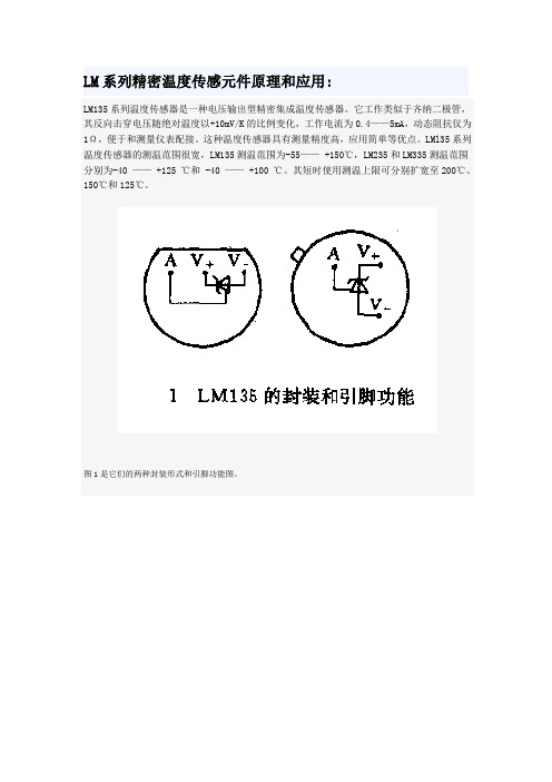
图1是它们的两种封装形式和引脚功能图。
图2是LMl35系列的内部电原理图:典型应用电路
1、基本测温电路。
iTEMP TMT72温度传感器操作手册说明书
Products Solutions Services操作手册iTEMP TMT72温度变送器BA01854T/28/ZH/04.20715255132020-10-20自下列版本起生效01.01(版本号)iTEMP TMT72目录Endress+Hauser 3目录1文档信息 (4)1.1文档功能 (4)1.2安全指南(XA) (4)1.3信息图标 (4)1.4工具图标 (5)1.5文档资料代号 (6)1.6注册商标 (6)2基本安全指南 (7)2.1人员要求 (7)2.2预定用途 (7)2.3操作安全 (7)3到货验收和产品标识 (8)3.1到货验收 (8)3.2产品标识 (8)3.3供货清单 (9)3.4证书和认证 (10)3.5运输和储存 (10)4安装 (11)4.1安装条件 (11)4.2安装 (11)4.3安装后检查 (16)5电气连接 (17)5.1接线 (17)5.2快速接线指南 (18)5.3连接传感器电缆 (18)5.4连接变送器 (19)5.5特殊接线指南 (20)5.6连接后检查 (21)6操作方式 (22)6.1操作方式概览 (22)6.2操作菜单的结构和功能 (25)6.3通过调试软件访问操作菜单 (27)6.4通过SmartBlue App 访问操作菜单 (29)7系统集成 (31)7.1设备描述文件概述 (31)7.2HART 通信的测量变量 (31)7.3支持的HART ®命令 (31)8调试 (34)8.1安装后检查 (34)8.2打开变送器 (34)8.3设置测量设备 (34)8.4写保护设置,防止未经授权的访问 (36)9诊断和故障排除...................379.1常规故障排除........................379.2现场显示单元上的诊断信息..............399.3通过通信接口查看诊断信息..............399.4诊断信息列表........................399.5事件日志............................409.6诊断事件概览........................409.7固件变更历史........................4110维护..............................4211维修..............................4211.1概述...............................4211.2备件...............................4211.3返厂...............................4211.4废弃...............................4212附件..............................4212.1设备专用附件........................4312.2通信专用附件........................4312.3服务专用附件........................4312.4系统组件............................4413技术参数..........................4513.1输入...............................4513.2输出...............................4613.3电源...............................4713.4性能参数............................4813.5环境条件............................5513.6机械结构............................5613.7证书和认证..........................5913.8补充文档资料........................6114操作菜单和菜单参数说明...........6214.1Diagnostics:诊断菜单.................6614.2Application:应用菜单.................7214.3System:系统菜单....................82索引.. (97)文档信息iTEMP TMT724Endress+Hauser1 文档信息1.1 文档功能文档中包含仪表生命周期各个阶段内所需的所有信息:从产品标识、到货验收和储存,至安装、电气连接、操作和调试,以及故障排除、维护和废弃。
ADI公司高精度数字温度传感器ADT7320介绍与应用指南
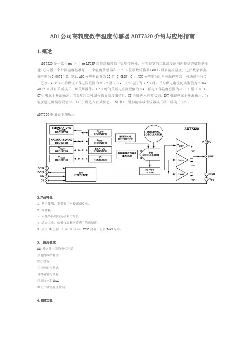
ADI公司高精度数字温度传感器ADT7320介绍与应用指南1.概述ADT7320是一款4 mm × 4 mm LFCSP封装高精度数字温度传感器,可在较宽的工业温度范围内提供突破性的性能。
它内置一个带隙温度基准源, 一个温度传感器和一个16位模数转换器(ADC),用来监控温度并进行数字转换,分辨率为0.0078°C。
默认ADC分辨率设置为13位(0.0625°C)。
ADC分辨率为用户可编程模式,可通过串行接口更改。
ADT7320的保证工作电压范围为2.7 V至5.5 V。
工作电压为3.3 V时,平均供电电流的典型值为210 A。
ADT7320具有关断模式,可关断器件,3.3 V时的关断电流典型值为2 A。
额定工作温度范围为−40°C至+150°C。
CT引脚属于开漏输出,当温度超过可编程临界温度限值时,CT引脚进入有效状态。
INT引脚也属于开漏输出,当温度超过可编程限值时,INT引脚进入有效状态。
INT和CT引脚能够以比较器模式或中断模式工作。
ADT7320框图如下图所示2.产品特色1. 易于使用,不需要用户校正或校准。
2. 低功耗。
3. 极佳的长期稳定性和可靠性。
4. 适合工业、仪器仪表和医疗应用的高精度。
5. 采用16引脚、4 mm × 4 mm LFCSP封装,符合RoHS标准。
3. 应用领域RTD及热敏电阻的替代产品热电偶冷结补偿医疗设备工业控制与测试食物运输与储存环境监控和HVAC激光二极管温度控制4.引脚功能1. 串行时钟输入。
串行时钟用于向ADT7320的任一寄存器输入数据或输出数据提供时钟。
2.串行数据输出。
数据在SCLK下降沿输出,而且在SCLK上升沿有效。
3.串行数据输入。
此输入端提供要载入器件控制寄存器的串行数据。
数据在SCLK的上升沿输入寄存器。
4.片选输入引脚。
此输入为低电平时,选择该器件。
此引脚为高电平时,该器件禁用。
智能化仪器原理及应用(第三版)课件:智能型温度测量仪

智能型温度测量仪
在RAM区中还开辟了4个通用工作寄存区, 共有32个通 用寄存器, 可以适用于多种中断或子程序嵌套的情况。 在MCS-51系列单片机内部, 还有1个由直接可寻址位组 成的布尔处理机, 即位处理机。 指令系统中的位处理指 令专用于对布尔处理机的各位进行布尔处理, 特别适用 于位线控制和解决各种逻辑问题。
智能型温度测量仪
MCS-51 简化结构框图与逻辑符号如图4-3所示。
XTAL1、 XTAL2: 内部振荡电路的输入/ RESET:
EA : 内外程序存储器选择端。 当 EA 为高电平时, 访问内部程序存储器; 当 EA 保持低电平时, 只访问外部 程序存储器, 不管是否有内部存储器。
智能型温度测量仪
P2.0相连。 存储器和8155的控制信号线分别与8031的相应端
相接, 从而可实现各种器件的读写操作。
智能型温度测量仪
4.2.2
温度是一个很重要的物理参数, 也是一个非电量, 自然界中任何物理化学过程都紧密地与温度相联系。 在 很多产品的生产过程中, 温度的测量与控制都直接和产 品质量、 生产效率、 节约能源以及安全生产等重要经济 技术指标相联系。 因此, 温度的测量是一个具有重要意 义的技术领域, 在国民经济各个领域中都受到相当的重 视。
智能型温度测量仪
与此同时, 将数据显示和打印出来; 也可将输出的开关 量经D/A 转换成模拟量输出, 或者利用串、 并行标准接 口实现数据通信。 整机工作过程是在系统软件控制下进 行的。 工作程序编制好后写入只读存储器中, 通过键盘 可将必要的参数和命令存入读/写存储器中。
智能型温度测量仪 图 4-2 智能型温度测量仪的工作流程
智能型温度测量仪
智能化仪器原理及应用
IMPAC红外温度传感器说明书
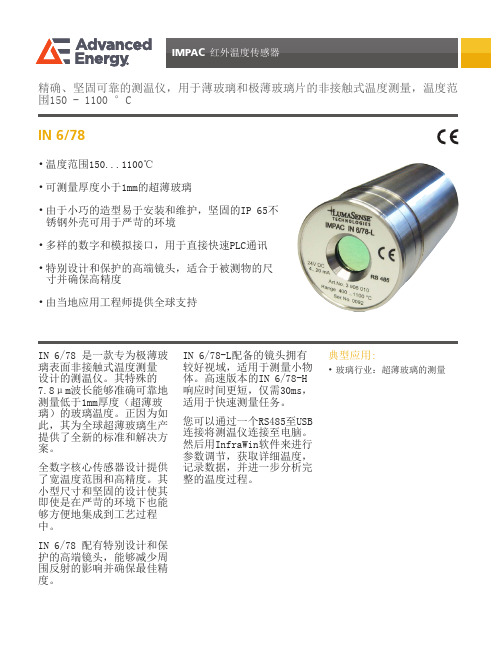
典型应用:•玻璃行业:超薄玻璃的测量IN 6/78 是一款专为极薄玻璃表面非接触式温度测量设计的测温仪。
其特殊的7.8μm波长能够准确可靠地测量低于1mm厚度(超薄玻璃)的玻璃温度。
正因为如此,其为全球超薄玻璃生产提供了全新的标准和解决方案。
全数字核心传感器设计提供了宽温度范围和高精度。
其小型尺寸和坚固的设计使其即使是在严苛的环境下也能够方便地集成到工艺过程中。
IN 6/78 配有特别设计和保护的高端镜头,能够减少周围反射的影响并确保最佳精度。
IN 6/78-L配备的镜头拥有较好视域,适用于测量小物体。
高速版本的IN 6/78-H 响应时间更短,仅需30ms,适用于快速测量任务。
您可以通过一个RS485至USB 连接将测温仪连接至电脑。
然后用InfraWin软件来进行参数调节,获取详细温度,记录数据,并进一步分析完整的温度过程。
IN 6/78精确、坚固可靠的测温仪,用于薄玻璃和极薄玻璃片的非接触式温度测量,温度范围150 - 1100 °C• 温度范围150...1100℃• 可测量厚度小于1mm的超薄玻璃• 由于小巧的造型易于安装和维护,坚固的IP 65不锈钢外壳可用于严苛的环境• 多样的数字和模拟接口,用于直接快速PLC通讯• 特别设计和保护的高端镜头,适合于被测物的尺寸并确保高精度•由当地应用工程师提供全球支持防护等级:IP 65 IEC 60529 (在配合状态下)工作位置:任意位置环境温度:0 ... 70 °C存储温度:-20 ... 80 °C相对湿度:非冷凝条件重量:410 g外壳:不锈钢CE 标志:符合欧盟关于电磁免疫的指令电源:24 V DC (18 ... 30 V DC), 波纹必须小于0.5 V功率消耗:最大 50 mA负载(模拟输出):最大 500Ω绝缘:电源,模拟输出和数字接口互相电气隔离注:MB是温度范围的缩写(德语:Messbereich)。
基于51单片机的温度警报器的设计单片机课程设计报告
《单片机原理与应用》课程设计任务书二级学院:电子信息与电气工程学院专业:班级:课程设计题目:基于单片机的数字温度报警器的设计姓名:学院:专业:班级:学号:指导教师:2011年 9月15日目录摘要41 引言41.1课题背景41.2研究容和意义62 芯片介绍62.1 DS18B20概述62.1.1 DS18B20封装形式与引脚功能72.1.2 DS18B20部结构72.1.3 DS18B20供电方式92.1.4 DS18B20的测温原理102.1.5 DS18B20的ROM命令122.2 AT89C52概述132.2.1单片机AT89C52介绍132.2.2功能特性概述133 系统硬件设计143.1单片机最小系统的设计143.2 温度采集电路的设计153.3 LED显示报警电路的设计164总结16致17参考文献18附录A总电路图19附录B原器件清单19附录C 温度报警器部分程序20摘要随着时代的进步和发展,温度的测试已经影响到我们的生活、工作、科研、各个领域,已经成为了一种非常重要的事情,因此设计一个温度测试的系统势在必行。
本文主要介绍了一个基于AT89C52单片机的数字温度报警器系统。
详细描述了利用数字温度传感器DS18B20开发测温系统的过程,重点对传感器在单片机下的硬件连接,软件编程以与各模块系统流程进行了详尽分析,对各部分的电路也一一进行了介绍,该系统可以方便的实现温度的采集和报警,并可以根据需要任意上下限报警温度,它使用起来相当方便,具有精度高、量程宽、灵敏度高、体积小、功耗低等优点,适合于我们日常生活和工、农业生产中的温度测量,也可以当做温度处理模块潜入其他系统中,作为其他主系统的辅助扩展。
DS18B20与AT89C52结合实现最简温度报警系统,该系统结构简单,抗干扰能力强,适合于恶劣环境下进行现场温度测量,有广泛的应用前景。
关键词:单片机;温度检测;AT89C52;DS18B20;1 引言1.1课题背景温度是工业对象中主要的被控参数之一,如冶金、机械、食品、化工各类工业生产中,广泛使用的各种加热炉、热处理炉、反应炉等,对工件的温度处理要求严格控制。
集成温度传感器LM35测量水温

《传感器技术》课程设计课题:集成温度传感器测量水温班级学生姓名学号指导教师淮阴工学院电子与电气工程学院2013年 6 月 21 日集成温度传感器LM35测量水温1. 系统方案设计1.1 概述如今,随着科学技术的发展,传感器的种类也日益增多,如AD公司生产的模拟电压输出型的温度传感器TMP35/36/37,它主要应用于环境控制系统、过热保护、工业过程控制、火灾报警系统、电源系统监控、仪器散热风扇控制等。
还有NATIONAL SEMICONDUCTOR生产的与微处理器相结合的测温及温度控制、管理的温度测量控制器LM80,它主要应用于个人计算机及服务器的硬件及系统的温度监控、办公室设备、电子测试设备等。
以及MAXIN公司生产的PWM风扇控制器及遥控温度传感器MAX1669,它主要应用于CPU冷却控制。
因此,测量外界的温度也有很多种方法,然而,由于热敏电阻及其放大电路受到环境的影响,在不同的条件下会出现不同的测温偏差;TMP35/36/37,LM80,MAX1669这些传感器的造价又太高,在相同条件下,由于测温精度、处理精度等多方面的因素,不同的通道也会出现不同的偏差,因此必须采用一种灵活的修正方式,这便用到了电压型温度传感器LM35D,它的线性好(10mV/℃),宽量程(0--100℃)高精度(+0.4℃),低成本,而且采集到的是电压型信号,易于处理,使得电路简单实用。
采集到的微弱电压信号经过放大器OP07放大十倍后送入ADC0804的输入端,A/D转换器(ADC0804)将模拟信号转换为数字信号后传给AT89C51,该系统以AT89C51单片机为核心,通过单片机编程可以实现高温(50℃)、低温(10℃)报警的控制,以及预置温度的控制,然后经过P1口将数字信号传送给74LS138译码器以及驱动器CD4511使LED八段数码管动态显示室温。
经实验调试,用该方法对0--100℃范围的温度测量时,测量误差+0.4℃,可靠性好、抗干扰性能强。
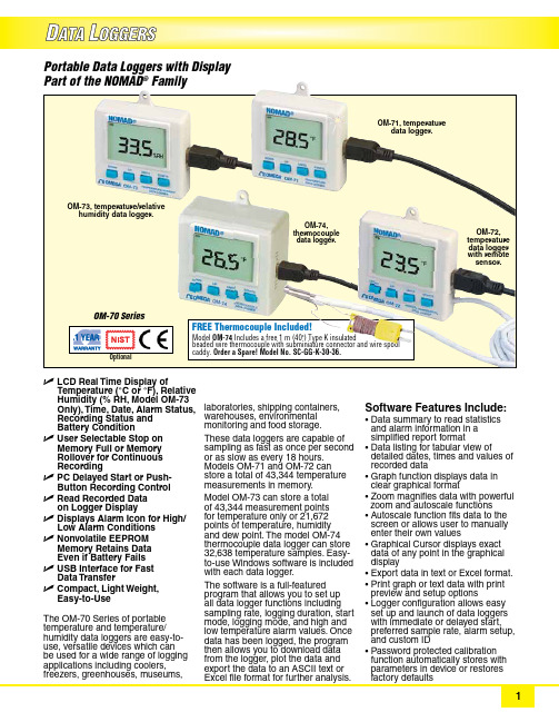
NOMAD OM-70系列胶囊式温度和温度 湿度数据记录仪产品说明书
The OM-70 Series of portable temperature and temperature/ humidity data loggers are easy-to-use, versatile devices which can be used for a wide range of logging applications including coolers, freezers, greenhouses, museums,Portable Data Loggers with Display Part of the NOMAD ® FamilyOM-73, temperature/relativehumidity data logger.OM-71, temperaturedata logger .OM-74, thermocouple data logger.OM-72, temperature data logger with remote sensor.Includes a free 1 m (40") Type K insulatedbeaded wire thermocouple with subminiature connector and wire spool Order a Spare! Model No. SC-GG-K-30-36.FREE Thermocouple Included!U LCD Real Time Display ofTemperature (°C or °F), Relative Humidity (% RH, Model OM-73 Only), Time, Date, Alarm Status, Recording Status and Battery ConditionU User Selectable Stop on Memory Full or Memory Rollover for Continuous RecordingU PC Delayed Start or Push-Button Recording Control U Read Recorded Data on Logger DisplayU Displays Alarm Icon for High/Low Alarm Conditions U N onvolatile EEPROM Memory Retains Data Even if Battery Fails U USB Interface for Fast Data TransferU Compact, Light Weight, Easy-to-Use laboratories, shipping containers, warehouses, environmental monitoring and food storage.These data loggers are capable of sampling as fast as once per second or as slow as every 18 hours. Models OM-71 and OM-72 can store a total of 43,344 temperature measurements in memory.Model OM-73 can store a total of 43,344 measurement points for temperature only or 21,672 points of temperature, humidity and dew point. The model OM-74 thermocouple data logger can store 32,638 temperature samples. Easy-to-use Windows software is included with each data logger.The software is a full-featured program that allows you to set up all data logger functions including sampling rate, logging duration, start mode, logging mode, and high and low temperature alarm values. Once data has been logged, the program then allows you to download data from the logger, plot the data and export the data to an ASCII text or Software Features Include:• D ata summary to read statistics and alarm information in a simplified report format • D ata listing for tabular view ofdetailed dates, times and values of recorded data • G raph function displays data in clear graphical format• Zoom magnifies data with powerful zoom and autoscale functions • A utoscale function fits data to the screen or allows user to manually enter their own values • G raphical Cursor displays exact data of any point in the graphical display• Export data in text or Excel format.• P rint graph or text data with print preview and setup options • L ogger configuration allows easy set up and launch of data loggers with immediate or delayed start, preferred sample rate, alarm setup, and custom ID • P assword protected calibration function automatically stores with parameters in device or restoresOMEGACARE SM extended warranty program is available for models shown on this page. Ask your sales respresentative for full details when placing an order. OMEGACARE SM covers parts, labor and equivalent loaners.Windows software displays data in graphical or tabular format.A calibration Window is provided in the software to simplify the calibration procedure • S tatus windows display unique ID of logger, battery voltage, memory used, sample rate, duration, alarm condition and logging status • M enu Bar along the topof the screen provides one click access to software functionsand battery.Ordering Example: OM-73, temperature/humidity data logger with display and OCW-1 OMEGACARE 1 year extended warranty adds 1 year to standard 1 year warranty.T ±0.7°C (1.3°F) -200 to 400°C (-328 to 752°F)1thermocouple wire grade used. 2The logger supported range is for stored temperature. The logger can only display temperatures up to 1999°F or 1999°CSpecificationsOM-71, OM-72, OM-73Ambient Temperature Measurement Range (Models OM-71, OM-73): -20 to 70°C (-4 to 160°F)External Sensor Temperature Measurement Range (Model OM-72):-40 to 70°C (-40 to 160°F)Storage Temperature: -40 to 77°C (-40 to 170°F)Temperature Accuracy:±0.5°C (±1°F), from -17 to 50°C (1 to 122°F)Temperature Resolution: 0.1°C (0.05°F)Relative Humidity Range (Model OM-73): 0 to 99% RH non-condensingRelative Humidity Accuracy (Model OM-73):±2% RH from 10 to 90% RH @25°C (77°F)Relative Humidity Resolution (Model OM-73): 0.05% RH OM-74Display Temperature Resolution: 0.1°C (0.2°F) up to 199.9°C or °F, 1°C (1°F) above 200°C or °FLogged Temperature Resolution: 0.1°C (0.2°F)Thermocouple Impedance: 50 Ω max for specified accuracy Cold Junction Temperature Accuracy: ± 0.3°C (±0.5°F) Operating Temperature: -18 to 55°C (0 to 131°F) Storage Temperature: -30 to 80°C (-20 to 175°F) GENERALSample Rate: 1 second to 18 hours user selectableAlarm Settings: Over/under alarm with visual indication LCD Display: Displays temperature, date, time, alarm condition recording status and battery condition Time Accuracy:±100 ppm @ 24°C (75°F)Measurement Capacity: OM-71, OM-72, OM-73:Non-volatile memory; 43,344 samples for temperature only,or 21,672 samples for temperature, humidity and dew point(Model OM-73); OM-74; 32,638 temperature samplesRecording Control: Start on button press, immediate after setup, or at a user specified date and timeRecording Mode: Stop on memory full, or continuous recording with memory rolloverMinimum System Requirements: 8MB of RAM, 2MB of disk space, 800 x 600 resolution, 1 free USB port Software Compatibility: Windows ® XP/VISTA/7 and 8 (32- and 64-bit)Interface: USB 2.0Power: OM-71, OM-72, OM-73:3V CR2032 lithium battery (included);OM-74: 3 AAA batteries (alkaline or lithium (included)Battery Life: 3 years (average)Dimensions:OM-71, OM-72, OM-73:6 H x 5.7 W x 1.3 cm D (2.36 x 2.24 x 0.51")OM-74: 5.7 H x 5.5 W x 3.0 cm D (2.25 x 2.15 x 1.2")Weight: OM-71, OM-72, OM-73: 91 g (3.2 oz)OM-74: 62 g (2.2 oz)。