Pathfinder最新版详尽使用手册-睿驰科技出品-Part1
Pathfinder最新版详尽使用手册

Pathfinder最新版详尽使用手册Pathfinder是一款非常受欢迎的角色扮演游戏系统,其最新版已经发布了。
如果你打算尝试这款游戏系统并使用最新版,就需要一本详尽的使用手册。
本文将介绍Pathfinder最新版的各个方面,帮助你深入了解、学习和使用这款游戏系统。
1. 角色建立在Pathfinder中,玩家可以创建自己的角色。
首先需要选择种族、职业、能力值、技能和特殊能力。
种族包括人类、精灵、矮人、侏儒、半身人等多种选择,每个种族都会影响你的能力和技能。
职业分为战士、法师、盗贼、神职者等,每个职业都有自己的特点和能力。
在选择能力值时,需要将六个属性点(力量、敏捷、体质、智力、感知、魅力)分配给这六项属性。
技能则涵盖多个方面,如摸骰子、攀爬、游泳、骑马等。
特殊能力包括魔法、特殊技能、武器专长等。
角色建立是你踏入Pathfinder世界的第一步,所以要认真考虑每个选项,并根据自己的喜好和需求做出最佳选择。
2. 游戏规则Pathfinder的游戏规则相当复杂,但也非常有趣,因此在游戏中要清楚地了解这些规则。
其中最重要的规则是行动轮,即每个人物在一个回合中所能做的事情。
每个回合都由一个标准行动、一个移动行动和一个自由行动构成。
标准行动可以是攻击、施法或采取行动,移动行动可以是移动、奔跑或爬行,自由行动可以是念咒、拔出武器等。
Pathfinder还有众多规则,如伤害、命中、魔法等,需要认真研究和遵守。
在游戏中,玩家需要与其他玩家、NPC和怪物进行战斗,并尽可能地保存自己的生命。
战斗结束后,还需要注意治愈和伤口的处理,以便更好地应对下一场战斗。
3. 魔法系统魔法是Pathfinder中的一个重要元素。
不同的职业有不同的魔法,如法师、神职者、德鲁伊等。
玩家需要准确掌握魔法的使用方法,才能在游戏中发挥最大的作用。
你需要掌握咒语的强度、范围、耗费和效果,以便在适当的时间使用它们。
在敌人使用魔法时,你也需要有相应的应对策略。
第三章 Pathfinder程序基础
§3-4 群体模型组织
二、改变组
在任何时刻一个对象可以从一个组移动到另一个组。改 变一个对象的组,在Navigation View中拖动对象到所想要 的组或者右键单击对象并选择改变组(Change Group…)。 这此时将显示一个对话框,允许用户选择新组。这个选项显 示新组只有是有效的组,该组才可以被改变。选择OK改变该 组。
§ 3-1 § 3-2 § 3-3 § 3-4 导航视图 3D和2D视图 视图选项 群体模型组织
Pathfinder 为疏散模型提供了三个主要视图: 2D视图、 3D视图和导航视图。这些视图表示用户当前的模型。如果 在一个视图中添加、删除或选择一个物体,其它视图将同 时反映出这一变化。下面会简要描述每个视图。
Navigation View:导航视图,该视图以分层次的格式列 出了模型中的所有对象。它可以通过名字快速定位和修改 物体。 3D View:3D视图,该视图显示了当前模型的 3D视图。可 以使用各种工具对该模型进行探索和修改。 2D View:2D视图,该视图非常类似于 3D视图,但它另外 为模型提供了一个捕捉网格和一个直角的视图。
§3-3 视图选项
二、人员显示
人员可以通过使用大量的选项显示出来。它们可以被视 为简单的形状,包括硬盘和圆柱体。它们还可以显示为艺 术家的人体模特或作为各自的人类化身,通过在它们的配 置来定义。这些选项存在于在视图(View)菜单和人员 (Agents)子菜单中。
§3-3 视图选项
三、房间着色
房间可以用各种方式上色。所有的着色选项在视图菜单 (View)下的房间着色子菜单(Color Rooms)中找到。默 认的选项是显示每个房间有独特的颜色。它们也可以通过人 员密度上色,这意味着将以红色房间代表人员更集中的房间 颜色,用蓝色代表房间人员集中更少的房间颜色。最后一个 选项是使用混合模式。在这种模式下,如果房间中包含人员, 房间只通过人员集中度来上色;否则,房间以它们独特的颜 色上色。
pathfinder规则书
pathfinder规则书?
答:"Pathfinder"规则书是一本详细的指南,它为"Pathfinder"角色扮演游戏提供了全面的规则和指导。
这本书包含了创建角色、战斗、技能、魔法、装备以及冒险等各个方面的详细说明。
1.角色创建:规则书首先指导玩家如何创建自己的角色,包括选择种族、职业、属性分配和技能选择等。
2.战斗:战斗是"Pathfinder"游戏的重要部分,规则书提供了详细的战斗规则,包括先攻检定、行动顺序、战斗策略和伤害计算等。
3.技能:规则书中包含了各种技能的详细描述和使用方法,玩家可以通过技能检定来执行各种任务或解决问题。
4.魔法:在"Pathfinder"世界中,魔法是常见的元素。
规则书提供了各种魔法的效果和使用方法,以及魔法师的职业特性和魔法物品的介绍。
5.装备:规则书中包含了各种装备的描述和属性,玩家可以根据自己的需要选择适合的装备来提升自己的能力。
6.冒险:规则书还提供了冒险指南,包括如何组织冒险队伍、探索未知地区和解决冒险中的挑战等。
总之,"Pathfinder"规则书是一本全面而详细的指南,它为玩家提供了在游戏中取得成功所需的所有信息和指导。
无论是新手玩家还是经验丰富的玩家,都可以通过阅读这本规则书来更好地理解和享受"Pathfinder"游戏的世界。
Pathfinder Roleplaying Game Beginner Box基础包转换指南说明书

基础包转换指南1这本手册是为玩家和游戏主持人准备的一份指南。
你应首先熟悉基础包中,英雄手册和游戏主持人指南的内容。
Pathfinder Roleplaying Game Beginner Box is published by Paizo lnc, under the Open Game License version 1.0a © 2000 Wizards of the Coast, Inc. Paizo, Paizo lnc, the Paizo golem logo, Pathfinder, Pathfinder Society, and GameMastery are registered trademarks of Paizo lnc; Pathfinder Roleplaying Game Beginner Box, Pathfinder Roleplaying Game, Pathfinder Adventure Card Game, Pathfinder Adventure Path, Pathfinder Campaign Setting, Pathfinder Cards, Pathfinder Flip-Mat, Pathfinder Map Pack, Pathfinder Module, Pathfinder Pawns, Pathfinder PlayerCompanion, Pathfinder Tales, and Rise of the Runelords are trademarks of Paizo lnc. © 2011, 2013, Paizo lnc. Chinese Translation © 2017 Paizo Inc.更进一步 2了解新规则 3阅读核心规则书的法术数据表 7目录The Pathfinder Roleplaying Game rules can be found online for free as part of the Pathfinder Roleplaying Game Reference Document at paizo.com/prd./beginnerbox基础包转换指南阅读志怪录的怪物数据表 8超越6级 10转换冒险模组 13中文译者:默'Soul 排版校对:卓尔出版人:张昊CREATIVE DIRECTOR • James Jacobs EDITOR-IN-CHIEF • F. Wesley SchneiderSENIOR EDITOR • James L. Sutter DEVELOPMENT LEAD • Sean K ReynoldsDEVELOPMENT TEAM • Logan Bonner, John Compton, Adam Daigle, Rob McCreary, Mark Moreland, and PatrickRenieEDITORIAL TEAM • Judy Bauer, Christopher Carey,and Ryan MacklinEDITORIAL INTERNS • Jay Loomis and Cassidy WernerLEAD DESIGNER • Jason BulmahnDESIGN TEAM • Stephen Radney-MacFarland and Sean KReynoldsINTERIOR ARTISTS • Alex Alexandrov, Alex Aparin, Eric Belisle, Matt Dixon, Andrew Hou, Steve Prescott,Scott Purdy, Wayne Reynolds, Dan Scott, and Tyler WalpoleAuthor • Sean K ReynoldsCUSTOMER SERVICE TEAM • Erik Keith, Justin Riddler, and Sara Marie TeterWAREHOUSE TEAM • Will Chase, Mika Hawkins, Heather Payne, Jeff Strand, and Kevin Underwood WEBSITE TEAM • Christopher Anthony, Liz Courts, Crystal Frasier, Lissa Guillet, and Chris Lambertz SENIOR ART DIRECTOR • Sarah E. RobinsonART DIRECTOR • Andrew VallasGRAPHIC DESIGNERS • Emily Crowell and SonjaMorrisPUBLISHER • Erik Mona PAIZO CEO • Lisa StevensCHIEF OPERATIONS OFFICER • Jeffrey AlvarezDIRECTOR OF SALES • Pierce Watters SALES REPRESENTATIVE • Cosmo Eisele MARKETING DIRECTOR Jenny Bendel FINANCE MANAGER • Christopher Self STAFF ACCOUNTANT • Ashley Gillaspie CHIEF TECHNICAL OFFICER • Vic Wertz CAMPAIGN COORDINATOR • Mike Brock PROJECT MANAGER • Jessica PriceLICENSING COORDINATOR • Michael KenwayPaizo Inc.7120 185th Ave NE, Ste 120Redmond, WA 核心规则书是一本大部头,书中包含了大量规则和选项,但你并不需要一股脑儿把它们全部弄明白。
pathfinder 疏散软件入门教程 users_guide使用手册

403 Poyntz Avenue, Suite BManhattan, KS 66502USA+1.785.770.8511User ManualPathfinder 2012DisclaimerThunderhead Engineering makes no warranty, expressed or implied, to users of Pathfinder, and accepts no responsibility for its use. Users of Pathfinder assume sole responsibility under Federal law for determining the appropriateness of its use in any particular application; for any conclusions drawn from the results of its use; and for any actions taken or not taken as a result of analyses performed using these tools.Users are warned that Pathfinder is intended for use only by those competent in the field of egress modeling. Pathfinder is intended only to supplement the informed judgment of the qualified user. The software package is a computer model that may or may not have predictive capability when applied to a specific set of factual circumstances. Lack of accurate predictions by the model could lead to erroneous conclusions. All results should be evaluated by an informed user.AcknowledgementsThis work was originally made possible by a Small Business Innovative Research (SBIR) grant by the United States National Science Foundation.We would like to thank Rolf Jensen and Associates for their assistance with testing and other suggestions that helped guide the development of the simulator.We would also like to thank the beta testers whose feedback helped us improve the software and incorporate more useful features.Note on use of “THEY” as singular pronounIn this document we use “THEY” as a singular pronoun. As stated in the Random House Dictionary of 1987:Long before the use of generic HE was condemned as sexist, the pronouns, THEY, andTHEM were used in educated speech and in all but the most formal writing to refer toindefinite pronouns and to singular nouns of general personal reference probablybecause such nouns are often not felt to be exclusively singular. Such use is not a recent development, nor is it a mark of ignorance.See also the online Oxford dictionary at: /words/he-or-she-versus-they.Table of Contents1. Introduction (1)Graphical User Interface (1)Model Representation (3)Simulation Modes (4)Limitations and Known Issues (4)Simulator Name (4)Contact Us (4)2. Pathfinder Basics (5)Navigation View (5)3D and 2D Views (6)Navigating the 3D view (6)Navigating the 2D view (7)Resetting the view (7)Filling the view (7)Drawing in the 3D and 2D views (8)View Options (8)Render Options (8)Occupant Display (9)Coloring Rooms (9)Room Opacity (9)Model Organization with Groups (9)Creating sub-groups (10)Changing groups (10)3. Creating Movement Space (11)Floors (11)Automatically creating floors (11)Manually creating floors (13)Changing the active floor (13)Showing all floors (14)Editing floors (14)Rooms (14)Adding new rooms (14)Adding thin walls to rooms (16)Splitting rooms (16)Separating and merging rooms (17)Obstructions/Holes (18)Arbitrarily-Shaped Obstructions (Desks, Tables, etc.) (18)Walls (19)Doors (20)Thin Doors (20)Thick doors (21)Stairs (22)Stairs between edges (23)Stairs extending from one edge (24)Ramps (25)Creating Elevators (26)Elevator Representation (28)Editing Elevators (28)Nominal Load (30)Connecting/Disconnecting Floors (30)Exits (30)Importing Files (31)Importing images (31)Importing CAD files (32)Importing PyroSim and FDS files (34)Working with Imported Data (34)Working with Images (34)Working with 3D CAD, PyroSim, and FDS files (34)Working with 2D DXFs (35)Filling in missing pieces (37)4. Creating Occupants (38)Profiles (38)Seeds (40)Customizing Occupants (41)Behaviors (41)Creating a new Behavior (41)Adding actions (42)Goto Waypoint action (43)Goto Rooms action (44)Goto Elevators action (44)Wait action (45)Adding Occupants (45)Individual placement (45)Group Placement (46)Placement in rooms (47)Redistributing Profiles and Behaviors (47)5. Editing and Copying Objects (49)Transforming and Copying Objects (49)Moving (49)Rotating (50)Mirroring (52)Manipulating Objects with Handles (53)Selecting and deselecting a handle (53)Editing a handle (54)Room handles (54)Thin door handles (54)Thick door handles (55)Stair and Ramp handles (55)Occupant handles (55)Waypoint handles (56)6. Model Analysis (57)Measuring Distances (57)Checking in-use Objects (59)Warnings and Errors (59)7. Simulating (61)Parameters (61)Starting and Managing a Simulation (63)Simulating via command-line (64)Stopping and Resuming a Simulation (64)Stuck Occupants (65)8. Results (66)Summary Report (66)Door Flow Rates (67)Room History File (67)3D Results (68)Navigating through a model (68)Displaying geometry input (69)Displaying occupants (69)Selecting Occupants (69)Viewing multi-floor problems (69)Animation playback (71)Refreshing Results (71)Viewing occupant paths (72)Controlling drawing detail/speed (72)Creating Movies (72)9. Index (75)FiguresFigure 1: An example of the graphical user interface (1)Figure 2: An example of the 3D Results (2)Figure 3: An example time history graph (3)Figure 4: 3D and 2D views (6)Figure 5: Render options (8)Figure 6: Predefined groups (10)Figure 7: Floor Creation panel (12)Figure 8: Auto floor creation and sorting (12)Figure 9: Adding a new floor (13)Figure 10: Floor property panel (14)Figure 11: Drawing a room with the polygon tool (15)Figure 12: Drawing a room with the rectangle tool (15)Figure 13: Adding a thin wall to a room (16)Figure 14: Dividing a room (16)Figure 15: Special case for drawing a thin wall (17)Figure 16: Merging rooms (17)Figure 17: Separating a room (18)Figure 18: Creating an obstruction (19)Figure 19: Subtracting walls (19)Figure 20: Door tool property panel (20)Figure 21: Adding a thin door to connect two touching rooms (21)Figure 22: Adding a thick door in the empty space between two rooms (22)Figure 23: Stair geometry requirements (23)Figure 24: Property panel for the two-point stair tool (23)Figure 25: Drawing stairs with the two-point stair tool (24)Figure 26: Property panel for the one-point stair tool (24)Figure 27: Drawing stairs using the one-point stair tool (25)Figure 28: Creating an Elevator (27)Figure 29: New Elevator dialog (27)Figure 30: Elevator representation (28)Figure 31: Elevator property panel (28)Figure 32: Elevator Priority dialog (29)Figure 33: Elevator Levels dialog (30)Figure 34: An exit door (31)Figure 35: Importing a background image (32)Figure 36: Dxf unit dialog box (33)Figure 37: Drawing rooms over a background image (34)Figure 38: Property panel for the floor extraction tool (35)Figure 39: A room extracted from a PyroSim file (35)Figure 40: Room extraction results from an imported 2D Floorplan (36)Figure 41: Using the door tool to fill a doorway (37)Figure 42: The Edit Profiles dialog (38)Figure 43: An example of the 3D model dialog. (39)Figure 44: Using a custom occupant profile (41)Figure 45: New Behavior dialog (42)Figure 46: Behavior Property Panel (42)Figure 47: Exit Chooser dialog (42)Figure 48: Behavior actions list (43)Figure 49: Example of action order for a behavior (43)Figure 50: Goto Waypoint creation panel (44)Figure 51: Goto Rooms creation panel (44)Figure 52: Goto Elevators creation panel (44)Figure 53: Wait creation panel (45)Figure 54: Adding occupants individually (45)Figure 55: Add Rectangular Group of Occupants Property Panel (46)Figure 56: Editing the distribution of profiles (46)Figure 57: Distributing occupants in a rectangular region (47)Figure 58: Distributing occupants through entire rooms (47)Figure 59: Edit Group Distributions dialog (48)Figure 60: Property panel for the translate tool (49)Figure 61: Graphically moving an object (50)Figure 62: Creating an array of objects by using the translate tool (50)Figure 63: Property panel for the rotate tool (51)Figure 64: Rotating an object (51)Figure 65: Creating an array of objects using the rotate tool (52)Figure 66: Property panel for the mirror tool (52)Figure 67: Mirroring an object (53)Figure 68: Manipulator handles (53)Figure 69: Handle property panel (54)Figure 70: Door handles (54)Figure 71: Stair/ramp handles (55)Figure 72: Agent handles (55)Figure 73: Waypoint handles (56)Figure 74: Connectivity example (57)Figure 75: Select Connected Components dialog (58)Figure 76: Selecting an entire graph of connected components (59)Figure 77: The Behavior tab of the Simulation Parameters Dialog (61)Figure 78: The Run Simulation dialog showing a partially complete simulation. (64)Figure 79: Listing for an example summary report file. (66)Figure 80: A time history plot for door flow rates (67)Figure 81: 3D Results for the multi-floor-stairwell example problem (68)Figure 82: Floor location dialog for 3D results (70)Figure 83: Multi-floor layout options in 3D results (FDS model courtesy of Andreas Niggemeyer) (71)Figure 84: Movie option dialogs (74)1.Introduction1.Pathfinder is an agent based egress and human movement simulator. It provides a graphical user interface for simulation design and execution as well as 2D and 3D visualization tools for results analysis.Graphical User InterfacePathfinder includes a graphical user interface that is used primarily to create and run simulation models.A screenshot of this user interface is shown in Figure 1. This screenshot displays a model that is being created from an imported floor plan image.Figure 1: An example of the graphical user interfacePathfinder also includes a second program designed specifically for high-performance visualization of 3D time history. The 3D Results program is shown in Figure 2. In this image, occupants are moving on a model that used an imported floor plan image.Figure 2: An example of the 3D ResultsIn addition to 3D visualization, Pathfinder also provides output in the form of 2D time history plots of CSV (comma separated values) out files and a text summary of room clearing times and doorway flow rates. An example time history plot can be seen in Figure 3. This plot shows the number of occupants in various rooms.Figure 3: An example time history graphModel RepresentationThe movement environment is a 3D triangulated mesh designed to match the real dimensions of a building model. This movement mesh can be entered manually or automatically based on imported data (e.g. FDS geometry).Walls and other impassable areas are represented as gaps in the navigation mesh. These objects are not actually passed along to the simulator, but are represented implicitly because occupants cannot move in places where no navigation mesh has been created.Doors are represented as special navigation mesh edges. In all simulations, doors provide a mechanism for joining rooms and tracking occupant flow. Depending on the specific selection of simulation options, doors may also be used to explicitly control occupant flow.Stairways are also represented as special navigation mesh edges and triangles. Occupant movement speed is reduced to a factor of their level travel speed based on the incline of the stairway. Each stairway implicitly defines two doors. These doors function just like any other door in the simulator but are controlled via the stairway editor in the user interface to ensure that no geometric errors result from a mismatch between stairways and the connecting doors.Occupants are modeled as upright cylinders on the movement mesh and travel using an agent-based technique called inverse steering. Each occupant calculates movements independently and can be given a unique set of parameters (maximum speed, exit choice, 3D model, etc).Simulation ModesPathfinder supports two movement simulation modes. In "Steering" mode, doors do not act to limit the flow of occupants; instead, occupants use the steering system to maintain a reasonable separation distance. In SFPE mode, occupants make no attempt to avoid one another and are allowed to interpenetrate, but doors impose a flow limit and velocity is controlled by density.You can freely switch between the two modes within the Pathfinder user interface and compare answers. More information about both modes is provided in the Technical Reference manual.Limitations and Known IssuesPathfinder 2011 does not integrate results from a fire model or provide support for complex behaviors (e.g. family grouping).Dynamic geometry is only partially supported (e.g. elevators are supported, but opening/closing doors, escalators, trains, etc. are not).Elevators are supported in evacuation-only circumstances. They do not model a general-purpose elevator system.Simulator NameThe name Pathfinder has been used previously to describe an egress simulator. The original Pathfinder is a 2D egress simulator created and used internally by Rolf Jensen and Associates. While the original Pathfinder inspired some of the features of the new simulator, the simulator described in this manual does not use any of the code from the original Pathfinder software.Contact UsThunderhead Engineering403 Poyntz Avenue, Suite BManhattan, KS 66502-6081USASales Information: sales@Product Support: support@Phone and Fax: +1.785.770.85112.Pathfinder BasicsPathfinder provides three main views for working on evacuation models: the 2D View, 3D view, and Navigation View. These views represent your current model. If an object is added, removed, or selected in one view, the other views will simultaneously reflect the change. Each view is briefly described below.∙Navigation View:This view lists all objects in the model in a hierarchical format. It can be used to quickly locate and modify objects by name.∙3D View: This view shows a 3D representation of the current model. The model can be explored and modified using various tools.∙2D View: This view is very similar to the 3D View, but it provides an additional snapping grid and an orthographic view of the model.Navigation ViewThe Navigation View helps you quickly find objects and data that are notalways easily accessible from the 3D and 2D views.The Navigation View is arranged in four groups:1.The Imported geometry group stores items that were imported froman image or an FDS, PyroSim, or DXF model. These objects do notaffect the simulation but are carried through to help with resultsanalysis. They can also be used to automatically extract rooms.2.The Profiles group contains the occupant profiles that have beencreated using the Edit Profiles dialog.3.The Behaviors group contains user-defined scripts that telloccupants how to behave.4.The Occupants group contains every occupant in the model. Ifoccupants are added to the model using a tool that adds more thanone occupant at a time, they will be collected in a sub-group.5.The Elevators group contains evacuation elevators in the model.6.The Floors group defines the floors in the model, and each floor contains all geometry necessaryto create a movement mesh, including room, stairway, ramp, door, and exit definitions.The buttons directly above the Navigation View perform the following actions:Auto Expand Selection when an object (or occupant) in the 3D or 2D view is selected, this action will expand the groups of the Navigation View as needed to show the selected object.Collapse All collapses all expanded groups in the Navigation View.Expand All expands all groups in the Navigation View (including sub-groups)The Floor box above the view can be used to manage floors. Any time a room, stair, ramp, or door is created it is added to a floor group matching the current selection in the Floor box. Changing the selection in the Floor box will cause the newly selected floor to be shown and all other floors to be hidden. Also, the Z property for all drawing tools will automatically default to the height of the floor currently selected in the Floor box. The visibility of any object or group of objects can always be manually set using the right-click context menu. This technique is useful if you want to show two floors at the same time (e.g. when creating a stairway).3D and 2D ViewsThe 3D and 2D views as shown in Figure 4 are the main views in which drawing is performed in Pathfinder. Both views contain tools to draw egress geometry and navigate in a model. The main difference between the two views is that the 3D view allows the model to be viewed from any direction, whereas the 2D view only allows viewing from one, orthographic direction. In addition, the 3D view contains no snap grid, whereas the 2D view does. The 3D view is entered by selecting the perspective camera, , and the 2D view is entered by selecting one of the orthographic cameras, , , or .At the top of the view is several buttons that show different camera modes, display options, and navigation modes. The panel under this is known as the property panel and is a selection context-sensitive panel. If a drawing tool is selected, it will show properties that can used to help draw. If no drawing tool is selected, and an object or several objects are selected, this panel will show the properties relevant to the selection. The panel of buttons on the left shows the drawing tools. The small panel at the bottom displays messages relevant to the current tool.Figure 4: 3D and 2D viewsNavigating the 3D viewSeveral tools are provided for navigating through the model in the 3D view, including orbit, roam, pan, and zoom tools.The main navigation tool for the 3D view is the Orbit tool, . By left-clicking and dragging, the model is rotated about its center point. The scroll-wheel can be used to zoom in and out on a specific point. Holding SHIFT on the keyboard and then clicking and dragging will pan the camera, and holding ALT while dragging will zoom in and out.Another navigation tool in the 3D view is the Roam tool, . This tool allows the camera to move in and out of the model at will. Without holding any keyboard keys, dragging the mouse will cause the camera to rotate about the camera’s location. So dragging the mouse up will make the camera look up, and dragging it left and right makes it look left and right. Holding CTRL while dragging will make the camera move forward and backward in the XY plane, and holding ALT while dragging will make the camera move up and down along the Z axis. This tool has a higher learning curve but is the most flexible viewing tool because it allows the camera to be placed anywhere in the model.The other navigation tools include a pan/drag tool, which moves the camera left and right and up and down, a zoom tool, which zooms in and out of the model while click-dragging, and a zoom box tool, which allows a box to be drawn that specifies the zoom extents.Pathfinder can also be navigated while using the Selection/manipulation tool, . To Orbit the camera while in perspective view, use a right-click and drag combination. Similarly, use a middle-click and drag to Pan in perspective view.Navigating the 2D viewNavigation in the 2D view is simpler than in the 3D view. The selection tool not only allows objects to be selected if single-clicked, but it allows the view to be panned by middle or right-clicking and dragging, and the view to be zoomed by using the scroll wheel. The drag and zoom tools are also separated into separate tools for convenience.Resetting the viewAt any time, the camera can be reset by pressing CTRL+R on the keyboard, or selecting Reset All tool, . This will cause the entire model to be visible in the current view. For all navigation tools but the Roam tool, reset will make the camera look down the negative Z axis at the model. For the roam tool, however, reset will make the camera look down the negative Y axis at the model.The camera can also be reset to the current selection at any time by pressing CTRL+E. This will cause the camera to zoom in on the selected objects and the orbit tool to rotate about the center of their bounding sphere.Filling the viewVery similar to resetting the camera, the view can be fit by pressing F on the keyboard or selecting the Fit View tool, . The difference between the Fill View and Reset All tools is that filling the screen does not change the view angle of the camera. Instead the camera will recenter/rezoom to fit the screen.Drawing in the 3D and 2D viewsDrawing can be performed in both the 3D view and the top 2D view. The 3D view allows the user to see the model from any angle, but most tools restrict drawing in the XY plane. The top view completely restricts drawing to the XY plane, but it also displays an optional snap grid. The snap grid size can be set under Edit snap grid spacing in the View menu, and it can be turned off by deselecting Show Snap Grid in the View menu.Drawing is performed in one of the two following modes:∙Normal Mode: Single-click a drawing tool button on the left side of the view. Draw the object using the instructions in the appropriate section of the manual. When the object has beencompleted, the drawn object(s) will be selected and the view will revert to the previousnavigation tool.∙Sticky Mode: Double-click a drawing tool’s button on the left panel before beginning to draw.When the object is completed, the same drawing tool will remain selected and more objects can be drawn with the tool. To escape this mode, press ESC on the keyboard, and the previousnavigation tool will be selected. A green dot on the tool’s icon indicates that the tool iscurrently in sticky mode. Single-clicking the tool’s icon again will turn off sticky mode but keep the tool selected.At any time while drawing, the user can press escape, which causes the current object to be cancelled and the previous navigation tool to be selected.For each tool there are often two ways to create its object. One way is to draw the object graphically using the mouse and keyboard. The other is to interactively create the object by typing information such as coordinates, widths, etc. in the tool’s property panel. The property panel will update the graphical preview immediately to reflect changes in the input. This allows fine-grained control in creating the object. The individual drawing tools are discussed in Creating Movement Space.View OptionsPathfinder provides a variety of view options for displaying both navigation geometry and imported geometry that can also aid with drawing. This includes options for rendering geometry, displaying agents, coloring rooms, and setting the transparency of rooms.Render OptionsIn the toolbar above the properties window in the 2D and 3D views, there are a number of buttons as shown in Figure 5 that control how geometry is rendered.Figure 5: Render optionsFrom left to right, the buttons are Wireframe Rendering, Solid Rendering, Show Textures, Show Object Outlines, Smooth Lighting, Display Navigation Geometry, and Display Imported Geometry.∙Wireframe Rendering: displays imported 3D geometry as wireframe only. This option is mutually exclusive with the solid rendering option. It is useful for drawing doors in the 2D view when 3D geometry has been imported.∙Solid Rendering: displays imported 3D geometry filled in. This is selected by default.∙Show Object Outlines: shows the outlines of 3D imported geometry. This is similar to showing the wireframe and solid versions at the same time.∙Smooth Lighting: uses a more realistic shading model to show all geometry. This may be a little slower to render on older graphics cards.∙Display Navigation Geometry: This toggles the visibility of all the navigation geometry. It does not affect anything else (including imported geometry and occupants).∙Display Imported Geometry: This toggles the visibility of all imported 3D geometry.Occupant DisplayOccupants can be displayed using a number of options. They can be viewed as simple shapes, including disks and cylinders. They can also be displayed as the artist’s mannequin or as their respective human avatars specified in their profiles. These options are available under View menu and Agents submenu.Coloring RoomsRooms can be colored in a variety of ways. All coloring options are available under the View menu and Color Rooms submenu. The default option is to display each room with a unique color. They can also be colored by occupant density, which means that rooms with a greater concentration of agents will be colored redder, and rooms with a lesser concentration will be colored bluer. The last option is to use a mixed mode. In this mode, the rooms are only colored by concentration if they contain agents; otherwise, they are colored with their unique colors.Room OpacitySometimes it is useful to be able to see through rooms and stairways, such as when drawing on top of an imported background image. To change the opacity of a set of components, select them and in the property panel, change the opacity. Opacity settings will carry through to 3D results visualization.Model Organization with GroupsThe main method of organization in Pathfinder is to use groups. In every model there are already some implicit groups that cannot be modified, including Imported Geometry, Profiles, Behaviors, Occupants, Elevators, and Floors as shown in Figure 6. Sub-groups can be created to further organize the model as discussed in the following sections.Figure 6: Predefined groupsCreating sub-groupsSub-groups can be created under Imported Geometry, Occupants, Elevators, and Floors (floors are discussed in the section, Floors). Groups can also be created in other sub-groups. To create a new group, right click the desired parent group in the navigation view and select New Group… or select New Group… from the Model menu. A dialog will display allowing the user to select the parent group (which will automatically be selected if performed from the right-click menu) and a name for the new group. Click “OK” to create the new group.Changing groupsAn object can be moved from one group to another at any time. To change an object’s group, drag the object to the desired group in the Navigation View or right click the object and select Change Group…. This will show a dialog that will allow the user to choose the new group. The options shown for the new group will only be valid groups for which the group can be changed. Select “OK” to change the group.3.Creating Movement SpacePathfinder is built on the idea of creating floor space on which occupants can walk. Every navigation component drawn in Pathfinder is some piece of flooring that can be travelled on, which can range from floors, to doorways, to stairs. Obstructions exist as holes in the floor.The main egress components include rooms, which are empty floor spaces bounded by walls, doors, which connect rooms on the same level, stairs/ramps, which connect rooms on different levels, and elevators, which connect multiple levels. Rooms can have any polygonal shape, and can never overlap on the same level. Doors can be either thick if they are occupying a doorway (the area between two rooms) or thin if they are simply connecting two touching rooms. Stairs/ramps are always rectangular and implicitly contain a thin door on each end to connect the adjacent rooms. Elevators can be any shape and can travel in any direction.To organize egress components, Pathfinder provides the concept of floors, which group together components at different Z locations.FloorsFloors are the primary method of organization in Pathfinder. At their most basic level, they are simply groups in which rooms, doors, stairs, ramps, and exits can be placed, but they also control the drawing plane for most tools and filtering of imported geometry.In every Pathfinder model, at least one floor must exist, and at any given time, there is one active floor. Whenever any navigation object is drawn, it will either be placed in the active floor or a subgroup of the active floor.By default when a new model is started, there is one floor at Z=0, and additional floors are either created automatically depending on where the geometry is drawn or manually created. In addition, new navigation components are automatically sorted into the appropriate floor when drawn.Automatically creating floorsWhen nothing is selected in the model, the Floor Creation panel is shown, as in Figure 7. This panel controls the automatic creation of floors and automatic sorting of new objects into floors.∙Auto sort egress components– If this is checked, navigation components are automatically sorted into the appropriate floor when created or modified; if this is unchecked, new navigation components are placed in the group specified under New Egress Components and remain in this group until manually moved.∙Automatically create floors – If this is checked, floors are automatically created as navigation components are created and modified.∙Floor height – This specifies the height at which new floors are automatically created. If a navigation component is created or moved to a location that is at least this distance from theprevious floor, a new floor will be created at a multiple of this distance from the previous floor.。
Pathfinder最新版详尽使用手册-睿驰科技出品-Part1
北京环中睿驰科技有限公司Pathfinder 使用手册主要介绍Pathfinder软件的详细使用方法。
Pathfinder使用手册 (5)1 软件介绍 (5)1.1 图形用户界(GUI) (5)1.2 模型展示 (7)1.3 模拟模型 (9)1.4 局限性和不足之处 (9)1.5 系统要求 (9)2 Pathfinder基础介绍 (11)2.1 导航视图 (11)2.2 3D和2D视图 (12)2.2.1 导航3D视图 (13)2.2.2 2D视图导航 (14)2.2.3 重置视图 (14)2.2.4 填充视图 (14)2.2.5 在2D和3D视图中绘制图形 (14)2.3 视图选项 (15)2.3.1 渲染选项 (15)2.3.2 人员显示 (16)2.3.3 设置房间颜色 (16)2.3.4 房间透明度 (16)2.4 用分组实现模型组织 (16)2.4.1 创建子分组 (17)2.4.2 变更分组的方法 (17)3 创建可移动区域 (17)3.1 Floors (17)3.1.1 自动创建楼层 (18)3.1.2 对存在的模块使用自动归集 (19)3.1.3 手工创建楼层 (19)23.1.4 更改活动楼层 (20)3.1.5 显示所有楼层 (20)3.1.6 楼层属性设置 (21)3.2 房间 (21)3.2.1 增加新房间 (21)3.2.2 绘制平面 (23)3.2.3 Thin Walls (24)3.2.4 分割房间 (24)3.2.5 分割和合并房间 (26)3.2.6 房间属性 (27)3.2.7 避免room-crossing (28)3.3 障碍物、Holes (29)3.3.1 绘制任意形状的障碍物(桌椅等) (29)3.3.2 Thick Walls (30)3.4 门 (31)3.4.1 薄门 (31)3.4.2 Thick Doors厚门、走廊 (32)3.4.3 门属性面板 (33)3.5 楼梯 (34)3.5.1 两边界间的楼梯 (35)3.5.2 绘制单边楼梯 (36)3.5.3 楼梯属性介绍 (37)3.6 斜坡Ramps (38)3.7 自动扶梯 (38)3.8 电动人行道 (39)3.9 电梯 (39)3.9.1 创建电梯 (40)3.9.2 展示电梯 (42)33.9.3 电梯属性介绍 (42)3.9.4 额定承载人数 (44)3.9.5 Connecting/Disconnecting floors (44)3.9.6 电梯呼叫组 (44)3.10 出口 (45)3.11 导入文件 (45)3.11.1 导入图像 (45)3.11.2 导入CAD文件 (46)3.11.3 导入Revit文件 (47)3.11.4 导入PyroSim和FDS文件 (49)3.12 使用导入的数据 (49)3.12.1 图像操作方法 (49)3.12.2 使用3D CAD,PyroSim和FDS文件 (50)3.12.3 使用2D DXFs数据 (51)3.12.4 填充缺损部分 (52)3.12.5 Flattening and Z location (53)3.12.6 视觉特性 (54)3.12.7 材料 (55)3.12.8 重构和快速编辑 (57)4Pathfinder使用手册1软件介绍Pathfinder是基础出口为主体和人类运动的模拟器。
Waves Nx Head Tracker 使用手册说明书

Nx Head TrackerUser GuideTABLE OF CONTENTSIntroduction (3)Why Head Tracking Matters (3)Functions and Features (4)Battery (4)Attaching the Nx Head Tracker to Your Headphones (4)Button Functions (4)LED Indications (5)Pairing Nx Head Tracker with Waves Nx 3D Audio Apps (5)Pairing Nx Head Tracker with the Nx Virtual Mix Room or Abbey Road Studio 3 Plugin (5)Head Tracking Application—Bluetooth Tracker Tab (6)Pairing Instructions (8)Updating the Firmware (9)Extras (12)Appendix A: Troubleshooter (12)Appendix B: Setting up a Session with Multiple Nx Tracker Users (13)Appendix C: Pairing Nx Head Tracker with Waves Nx 3D Audio Apps (15)IntroductionThe Waves Nx Head Tracker is a small Bluetooth device that attaches to your headphones. It tracks your head movements in 360 degrees to enhance the realistic and immersive 3D audio experience created by Waves Nx technology.The Nx Head Tracker can be used together with several types of Waves Nx software. Use the Nx Head Tracker along with the Nx desktop and mobile apps for 3D audio on headphones to experience the music, movies, and games you love, in 3D audio— on your desktop, laptop, tablet or mobile device.Audio professionals can use the Nx Head Tracker, along with the Nx Virtual Mix Room Over Headphones plugin or Abbey Road Studio 3, to recreate on headphones the ideal spatial acoustics of a high-end studio, thus improving your headphone mixing and recording experience.Why Head Tracking MattersWhen you hear sounds in the real world, your head movements help your brain create a sense of three-dimensional audio depth. As your head moves, your brain remembers where the sound used to be and where it is now, combines this with its knowledge that the head (and not the external source) has moved, and uses this information to locate the external source and construct a three-dimensional “audio scene.”However, when you listen to sound on headphones, the audio scene constantly shifts with your head, so your experience of three-dimensional auditory space is gone.By tracking your head movements and adjusting the audio to the orientation of your head, the Nx Head Tracker (combined with Nx software) helps reconstruct the realistic three-dimensional audio experience of sounds coming at you from external sources in the real w orld.There are several ways you can track your head movements to enhance the Nx experience:•Use the Nx Head Tracker device.•Use your computer’s camera.•If you are using the Nx Virtual Mix Room or the Abbey Road Studio 3 plugin, you can use both methods simultaneously (“Sensor Fusion” mode) toachieve a faster tracking rate.For a detailed comparison between these options, see the Overview tab of theNx Head Tracker webpage.Functions and FeaturesBatteryThe Nx Head Tracker device works with any standard AAA battery,which provides approximately 40 hours of use. Replace the battery through the bottom hatch. The device will go to sleep automatically after a few minutes if it’s not connected or not moving. In sleep mode, the battery life can last for months.Attaching the Nx Head Tracker to Your Headphones After you insert a AAA battery into the Nx HeadTracker, position the device at the top-center ofthe headphone arc, with the Nx logo facingforward (i.e., the battery in the back). The NxHead Tracker will not track your head movementsproperly if you place it off-center or facingbackward.Wrap the strap around the headphone’sheadband and attach it to the hook on the otherside. The strap can be disconnected at both endsfor replacement and any standard rubber bandcan be used if needed.Button FunctionsA short press (under two seconds) in any state will place the unitin advertising mode. In this mode, the device can be detected and paired with your computer.LED IndicationsPairing Nx Head Tracker with Waves Nx 3D Audio AppsFor detailed instructions about how to pair the Nx Head Tracker device with the Waves Nx desktop and mobile apps for 3D audio on headphones, refer to the apps’ user guides:•Waves Nx for W indows and Mac – User Guide •Waves Nx for M obile (iOS and Android) – User GuidePairing Nx Head Tracker with the Nx Virtual Mix Room or Abbey Road Studio 3 PluginTo use the Nx Head Tracker device with the Nx Virtual Mix Room plugin, you must first pair them. This is done from a dedicated head tracking application that opens and closes automatically when you open and close the plugin. For head tracking to be enabled, the application must remain open. If the application is closed, head trackingwill stop. This will not affect the plugin itself or your DAW in any way; you can simply restart the head tracking application using the Settings button (Abbey Road Studio 3) or Restart button (Nx Virtual Mix Room). This reestablishes tracking. SleepLED off AdvertisingBlinks blue ConnectingSolid blue ConnectedBlinks blue every 15 seconds Low BatteryRed instead of blue IdentifyingBlinks white Updating Blinks greenHead Tracking Application—Bluetooth Tracker TabDevice List – This list will show all available Nx Head Tracker devices. Up to six devices can be connected simultaneously.Connect (check box) – Check or uncheck this box in order to connect or disconnect an Nx Head Tracker device that appears in the device list.Refresh Device List – This control will erase the list and rescan for Nx Head Tracker devices.Automatic Connect –When On, the application automatically connects with any Nx Head Tracker device it detects. When Off, the application detects Nx Head Tracker devices, but the user must initiate the connection,Open Bluetooth Settings – Used to manually un-pair a device when needed as a troubleshooting step.Rename – This control lets you rename your Nx Head Tracker device. The name is permanent, and the device will advertise itself by the given name.Identify – This control will make the Nx Head Tracker device blink white. This is helpful to identify a certain device among several.Update – This control will initiate FW updates to the Nx Head Tracker’s firmware. A message will appear when a firmware update is available for your Nx Head Tracker device.Pairing Instructions1. Open the Nx Virtual Mix Room or Abbey Road Studio 3 plugin. The head trackingapplication will launch automatically.2. In the Head Tracking application, go to the Bluetooth Tracker tab.3. Power on the Nx Head Tracker. Make sure your computer’s Bluetooth is on and thatit supports Bluetooth Low Energy (BLE).4. Connect to the Head Tracker device(s):The Nx Head Tracker device will automatically be recognized and added tothe list of devices showing in the Bluetooth Tracker tab. Mark the Connectcheck box and see the numbers under Tracking Data start to change as theNx Head Tracker moves.Updating the FirmwareThe Nx Head Tracker can update its firmware over Bluetooth. The device leaves the factory with firmware version 1.17v1.13. As we continue to develop the Nx device, firmware updates will be released. When a firmware update is available, a message will appear in red in the Device Status window. Follow these instructions to update the firmware:1)Turn on your Nx Head Tracker device. Find your device in the IMU DeviceName column of the Waves Head Tracker application and check Connect.2)Confirm that the firmware version on the Nx Head Tracker device is1.30v1.13. You will see red text indicating that a Firmware update isavailable.3)Click the Update button and follow the update dialog box:a)Press Update.b)Press OK to proceed to the firmware update.c) The Nx Head Tracker device will restart. A green light indicates thatthe device is in update mode. The Waves Head Tracker application will automatically connect to the device and start updating thefirmware. The update will require a few minutes. A dialog box will indicate that the update has finished successfully.d) The Nx Head Tracker device will then automatically restart. Its LEDwill turn blue.e) You will now need to reconnect the device by repeating the sameactions as in Step 1 (above). Once the device is reconnected, the firmware version number changes to 1.30v1.13.4)Once the Nx Head Tracker’s firmware is updated to 1.30v1.13, turning offthe device (long button press) will put the device in sleep mode (indicatedby the LED flashing red). In this mode, the battery should last over sixmonths.During the update, try not to handle the device; leave it stationary on a flat surface. You can update only one Nx Head Tracker device at a time.While the device is updating, make sure that no other system is using the Waves HeadTracker application in close proximity. Two nearby systems using the application at the same time can interfere with each other.ExtrasAppendix A: TroubleshooterProblem Possible SolutionsHead does not move in GUI – no tracking 1. Verify head tracking is ‘on’ in plugin GUI.2. Check if tracker app is running.3. Play audio through the plugin (plugin on CPU).4. Check tracking rate box in plugin GUI.Head tracking application is not running 1. Restart head tracking through the plugin (Abbey Road Studio 3“Settings”) or Nx Virtual Mix Room “Restart”).2. Inactivate/reactivate plugin.Nx Head Tracker will not connect (Windows only) 1. Make sure that the Nx Head Tracker is NOT currently paired to yourcomputer in the Bluetooth Settings menu. If it is paired with thecomputer, remove it manually.Nx Head Tracker loses connection and doesn’t move smoothly 1. Try using a new battery.2. Try to have the Nx Head Tracker and the Bluetooth receivercloser together.3. If you are using a BT-USB dongle on a desktop, connect thedongle on the front panel or on an extension for better BT reception.Nx Head Tracker is tracking my movements but in wrong directions 1. Make sure the Nx Head Tracker is mounted on the top of theheadphone arc with the logo side facing forward. L & R on the Nx Head Tracker should correspond to L & R on yourheadphones. Inaccurate positioning of the Nx Head Tracker will result in inaccurate head tracking.Head tracking shows some latency 1. Try to increase the tracking rate (optimally up to 30 fps).2. Try to lower the buffer size.3. In some DAWs, to run in the user-set buffer size, Nx need to beon the master buss or on a live input AUX path.Appendix B: Setting up a Session with Multiple Nx Tracker Users Up to six Nx Head Tracker devices can be used simultaneously. This lets engineers and artists work collaboratively in the same Nx mixing environment—each participant will have a an individual Nx mix and personal head tracking.The two examples below are applicable to the Nx Virtual Mix Room and Abbey Road Studio 3 plugins.Example 1: Mixing session with three mix engineers monitoring through Nxwith three Nx Head Trackers1.Route the mix to a master aux bus.2.Send the master aux bus to the main output bus and to three other auxes forNx monitoring. We will call these auxes “Nx aux 1, 2, and 3.”3.Route each of the Nx auxes to separate headphone outputs (i.e., Nx aux 1to headphone out 1 /2, Nx aux 2 to headphone out 3/ 4, and so on).4.Open plugin on each of the Nx auxes.5.If the Waves HeadTracker application is not open, open it now. Power up the threeNx Head Trackers.6.Connect the Nx Head Trackers.Mac: The Nx Head trackers are detected automatically and added to the list ofdevices in the Waves Head Tracker application. Check the Connect checkbox.Windows: Click the “Open Bluetooth Settings” button and pair the three NxHead Trackers. The Nx Head Trackers will be detected automatically andadded to the list of devices in the Waves Head Tracker application. Check theConnect checkbox.e the Waves HeadTracker application to assign each Nx Head Tracker aunique name. This helps to identify the devices.8.For each Nx plugin, select one of the Nx Head Trackers from the Tracking Devicemenu. Make sure that each Nx aux channel is assigned to the correctheadphones. Incorrect selection will result in the movements of one Nx HeadTracker listener affecting t he sound orientation of another listener.Once all the Nx Head Trackers are assigned to the correct plugin instances and are routed separately to the listeners’ headphones, all three mix engineers will experience Nx spatial imaging: each with individual head tracking and their own aux mix.Example 2: Recording session with one engineer and two musicians1.Create a master track bus and two auxiliary buses for the musicians’ headphonemonitor mix. We will call these buses “Nx Master” and “Nx Monitor 1 and 2."2.Route the Nx Master bus to the engineer’s headphones, and the Nx Monitor buses 1and 2 to two separate headphone outputs (one for each musician).3.Open a plugin instance on each of the Nx buses.4.If the Waves Head Tracker application is not open, open it now. Power up the threeNx Head Trackers.5.Connect the Nx Head Tracker.Mac: The Nx Head trackers are detected automatically and added to the list ofdevices in the Waves Head Tracker application. Check the Connect checkbox.Windows: Click the “Open Bluetooth Settings” button and pair the three Nx HeadTrackers. The Nx Head Trackers will be detected automatically and added to the list of devices in the Waves Head Tracker application. Check the Connect checkbox.e the Waves Head Tracker application to assign each Nx Head tracker a uniquename. This helps to identify the devices.7.For each plugin instance, select one of the Nx Head Trackers from the TrackingDevice menu. Make sure that on the "Nx Master," you select the engineer’s head tracker, and on “Nx Monitor 1 and 2," you select the Nx Head Tracker that isused by the musician receiving this monitor bus. Incorrect selection will result inthe movements of one Nx Head Tracker listener affecting the sound orientation ofanother listener.Once all the Nx Head Trackers are assigned to the correct Nx or Abbey Road Studio 3 instances and are routed separately to the listeners’ headphones, each musician will hear his own monitor mix with Nx and head tracking, and the mix engineer will hear the master mix with head tracking through headphonesAppendix C: Pairing Nx Head Tracker with Waves Nx 3D Audio AppsFor detailed instructions on how to pair the Nx Head Tracker device with the Waves Nx desktop and mobile apps for 3D audio on headphones, see the apps’ user guides: Waves Nx for Windows and Mac User GuideFor Mobile (IOS and Android) Waves Nx User Guide。
Osprey Farpoint Trek 75 55 70 50 户外登山包用户手册说明书
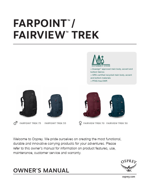
OWNER'S MANUALFARPOINT TM/FAIRVIEW TMTREKFARPOINT TREK 75FARPOINT TREK 55FAIRVIEW TREK 50FAIRVIEW TREK 70 Welcome to Osprey. We pride ourselves on creating the most functional, durable and innovative carrying products for your adventures. Please refer to this owner’s manual for information on product features, use, maintenance, customer service and warranty.+ bluesign ® approved main body, accent and bottom fabrics+ GRS-certified recycled main body, accent and bottom materials + PFAS-free DWRSHARED FEATURES1 S towable AirCover ™ protects checked packs and doubles as a raincover2 Large front panel access for easy packing3 Zippered lower compartment access with divider4 Removable sleeping pad straps5 M ulti-function sleeve carries a hydration reservoir or tablet/laptop in padded case6 Upper side and front panel compression straps stabilize loads7 Small zippered top pocket stores smaller items8 Zippered hipbelt pockets9 Padded tubular side grab handle 10 Durable stretch-woven side pockets11 Attachment loops/external attachment points for Farpoint/Fairview Travel Daypack or Daylite ™12 Vertical front panel quick-zip pocket +Dual internal compression straps with fabric wings keep clothes neat8109512634127111FABRICMAIN bluesign ® approved 420D recycled nylon, PFAS-free DWR ACCENT bluesign ® approved 500D recycled high tenacity nylon, PFAS-free DWR BOTTOM b luesign ® approved 500D recycled high tenacity nylon,PFAS-free DWRPRODUCT PROMISEThe Farpoint/Fairview Trek packs are purpose-built for adventure travel thatinvolves extended time on the trail. With smart organization that makes it easy to find your gear, a highly ventilated AirSpeed™ backpanel for humid climates and an easily adjustable suspension for the perfect fit, there’s no better option.FARPOINT TREK 55 MEN'SSPECS O/S Cubic Inches 3356Liters 55 Pounds 4.23 Kilograms1.92 Inches 28h x 15w x 12d Centimeters 72h x 39w x 31d LOAD RANGE20-50 lb | 9-23 kg INCLUDED AirCover MADD-ON(S) Resevoir 3LFARPOINT TREK 75 MEN'SSPECS O/S4577 CubicInchesLiters 75 Pounds 4.63Kilograms 2.10 Inches 30h x 17w x 14d Centimeters 77h x 42w x 36d LOAD RANGE20-50 lb | 9-23 kg INCLUDED AirCover LADD-ON(S) Resevoir 3LFAIRVIEW TREK 50 WOMEN'SSPECS O/S3051 CubicInchesLiters 50 Pounds 4.08Kilograms1.85 Inches 24h x 15w x 13d Centimeters 62h x 38w x 32d LOAD RANGE20-50 lb | 9-23 kg INCLUDED AirCover MADD-ON(S) Resevoir 3LFAIRVIEW TREK 70 WOMEN'SSPECS XS/S4272 CubicInchesLiters 70 Pounds 4.56 Kilograms2.07 Inches 27h x 16w x 14d Centimeters 68h x 41w x 36d LOAD RANGE20-50 lb | 9-23 kg INCLUDED AirCover LADD-ON(S) Resevoir 3LCARRYSIZING / FITWOMEN'S-SPECIFIC FIT+ Shorter torso length.+ N arrower, shorter harness with curves designed to accommodatemost women's necks, shoulders and chests.+ A hipbelt designed to wrap naturally around the curves of a woman'ships, offering better load stabilization and support.FARPOINT TREK - MEN'STORSO o/s 17-22" / 43-56 cmFAIRVIEW TREK - WOMEN'STORSO o/s 14-19" / 36-48 cmHOW TO MEASURE YOUR TORSO FOR YOUR PACK123334LOAD LIFTERS STERNUM STRAPHARNESSHIPBELTFRAMEAIRSPEEDBACKPANEL1 AIRSPEED ™ SUSPENSION+ 4 mm LightWire peripheral frame effectivelytransfers the load from harness to hipbelt 2 AIRSPEED BACKPANEL+ 3D-tensioned breathable mesh backpanel withside ventilation3 HARNESS + S oft, edgeless padded mesh harness with 4+”of adjustability for a perfect fit+ A djustable sternum strap with magnetic bitevalve attachment4 HIPBELT+ E dgeless padded mesh offers a soft, breathablecontact surface and heavy load support+ Breathable, stowaway reverse-spacermesh hipbelt5 ADJUST HARNESS+ T he harness straps should wrap fully around the shoulders with no gapsbetween the pack and back.+ T he padded part of the harness straps should end 1-2" / 2.5-5 cm belowthe armpit. And the harness should have 1-2" / 2.5-5 cm of webbingremaining.ADJUST TORSO LENGTH+ L ocate the harness yoke—this is where the harness straps come togethernear the base of the user’s neck. Locate the C7 vertebra—the largeprotruding bone at the base of the neck. The yoke should be 1-2” / 2.5-5cm below the C7 vertebra.+I f the torso length is too short or tall, adjust the torso length of the pack.(Follow instructions in step 6.)3 TIGHTEN HARNESS+ T ighten the shoulder harness straps to tension by pulling themdown and back.4 TIGHTEN LOAD LIFTERS+ T ighten the load lifters to tension by pulling them up and forward. This willpull the pack close to the body to help stabilize the load.1 P OSITION THE PACK+ Completely loosen the pack’s hipbelt, harness and load-lifter straps.+ L oad the pack with 10-20 lbs/4-9 kg of gear.+ P ut the pack on and make sure the hipbelt is centered and rests over thehipbone. The hipbelt padding should sit halfway above and below thehipbone.2 BUCKLE HIPBELT+ Buckle and evenly tighten the hipbelt using Osprey’s cross body ErgoPull.+ T he padding of the hipbelt should wrap around the hips with approximately1-3" / 2.5-6 cm of webbing between the buckle and the hipbeltwhen tightened.FIT6 ADJUSTABLE HARNESS (TORSO LENGTH)M - 65L / 50L W - 65L / 50L+ I dentify the harness plugs located in one of the four sizing loops on thebackpanel.+ G rab the plug's pull loop with thumb and forefinger and pull the harness'sLightWire extension out and to the sides of the pack. This releases the harnessand allows it to slide up and down.+ S lide the harness up or down along the LightWire rails to the appropriate torsolength.+ T here are two load-lifter ladder lock options. Correspond the lower two or uppertwo backpanel settings to the lower or upper load-lifter ladder lock.7 STERNUM STRAP+A djust the sternum strap to approximately 2"/5 cm below the collarbone;buckle and tighten to tension.FOR PROTECTIVE USE DURING TRAVEL 1 Locate AirCover in the top pocket of the pack.2 R emove AirCover from compartment, slip it over the whole pack and zip shut.3T he AirCover offers travel features like lockable zippers, an ID card holder and grab handles for travel convenience.FOR USE AS RAINCOVER 1 Locate AirCover in the top pocket of the pack.2 R emove AirCover from compartment and slip it over the top and bottom of the pack.3T ighten the cord lock at the bottom of raincover to tension raincover into place.4 T o detach raincover, unfasten toggle from cord loop.Tip: To prevent mildew, allow raincover to dry entirely before storing.AIRCOVER50 L / 55 L / 70 L / 75 LStowable AirCover protects checked packs and doubles as a raincover.FRONT PANEL ATTACHMENT POINTS50 L / 55 L / 70 L / 75 LCord loops, located on the front panel of the pack, allow gear to be easily rigged tothe outside of the pack.DAYPACK FRONT BODY CARRY50 L / 55 L / 70 L / 75 LThe Farpoint/Fairview Trek is equippedwith male buckles on the harness to attach daypacks with campatible female buckles.FRONT PANEL ATTACHMENT FOR FARPOINT/FAIRVIEW TRAVEL DAYPACK50 L / 55 L / 70 L / 75 LThe Farpoint/Fairview Travel Daypack integrates securely and conveniently with theStraightJacket compression of the main pack.FRONT PANEL ATTACHMENT FOR DAYLITE ™50 L / 55 L / 70 L / 75 L1T hread the ladder locks or upper side compression straps of the daypack through the corresponding upper two cord loop attachment points on the Farpoint/Fairview Trek.2T hread the ladder locks or webbing hipbelt of the daypack throughthe corresponding lower two cord loop attachment points on the Farpoint/Fairview Trek.3U tilize the StraightJacket compression for added security.DUAL SIDE POCKETS50 L / 55 L / 70 L / 75 LTOPLID WITH POCKET50 L / 55 L / 70 L / 75 LZIPPERED HIPBELT POCKETS50 L / 55 L / 70 L / 75 LLARGE FRONT PANEL ACCESS AND INTERNAL COMPRESSION STRAPS WITH FABRIC WINGS50 L / 55 L / 70 L / 75 LThe large front panel U-zip access allows for easy packing when traveling while the internal compression straps with fabric wings keep clothes and other items neat and organized.HIDDEN INTERNAL POCKET50 L / 55 L / 70 L / 75 LFRONT PANEL STRAIGHTJACKET COMPRESSION STRAPS50 L / 55 L / 70 L / 75 LUpper and lower compression straps provide added stability when the pack is not full or offer additional attachment points for carryinggear on the outside of the pack.SLEEPING PAD STRAPS50 L / 55 L / 70 L / 75 LRemovable sleeping pad straps allow for quick,secure external gear attachment.LOWER COMPARTMENT WITH REMOVABLE DIVIDER50 L / 55 L / 70 L / 75 LA lower zippered compartment creates a space dedicated for items such as dirty shoes or a sleeping bag. When seperate storage is not needed a divider can be detached which will add volume to the main compartment of the pack.INTERNAL HYDRATION/LAPTOP SLEEVE50 L / 55 L / 70 L / 75 LThe dedicated internal multifunction sleeve doubles as either a hydration reservoir sleeve or laptop sleeve (recommended to have laptop in a protective case as internal sleeve is not padded). This keeps the items close to the back for safe keeping and also provides proper weight distribution when carrying a pack.INSERTING RESERVOIR+ I nsert reservoir into sleeve.+ U se the small hanging webbing loop to attach the reservoir into place in a vertical orientation.+ Locate the H2O raindrop label next to a small hole on the backpanel of thepack and route the reservoir hose from inside to outside the pack.+ E lasticized routing straps on right or left side of the pack’s harness hold the reservoir hose in place.+ Compatible with any reservoir up to 3L.For more information on this and other products, pack care, how to pack your pack, our lifetime guarantee, or to contact Osprey customer service, visit .。
最新SurvCE快速操作手册

S u r v C E快速操作手册Carlson SurvCE使用手册仅供学习与交流,如有侵权请联系网站删除谢谢38目录Carlson SurvCE使用手册 (1)目录 (2)1、前言 (3)2、启动SurvCE (3)3、菜单介绍 (4)3.1 图标说明 (4)3.2 菜单介绍 (7)4、测量作业的实施 (8)4.1项目设置 (8)4.1.1 创建新项目 (8)4.2 测量菜单 (15)4.2.1 设置测站点 (15)4.2.2 设置后视点 (21)4.2.3 后视测量 (21)4.3 进行测量 (22)4.4 放样 (23)4.4.1 放样点 (23)4.4.2 放样线/弧 (25)五、数据传输 (35)5.1 数据传输 (35)5.2 输入/输出ASCII 文件 (37)5.2.1 导入ASCII文件 (37)5.2.2导出ASCII文件 (38)仅供学习与交流,如有侵权请联系网站删除谢谢381、前言Carlson SurvCE是Carlson软件公司对生产最佳测量产品的承诺。
SurvCE2.0软件或更高版本运行在Windows CE3.0或更高版本和手控个人计算机上。
该软件全中文菜单式操作,思路清晰、简单明了。
2、启动SurvCE仪器开机,会出现如下显示:双击SurvCE图标,即可启动SurvCE。
仅供学习与交流,如有侵权请联系网站删除谢谢383、菜单介绍SurvCE软件共包含五大菜单:文件、仪器、测量、COGO、道路。
3.1 图标说明图标用户可设置Survce2.0显示传统字符图标或新的图形图标来实现几种功能。
用户可点击EQUIP键,选择配置并点击“使用图形图标”进行切换。
该图标读取一个测量项目(ALT-R)仅适用于全站仪。
该图标通过推进设备来旋转至测量仅供学习与交流,如有侵权请联系网站删除谢谢38点。
该图标用于存储点。
该功能也可通过键盘输入实现。
切换到一个对话框,用户于此可设置GPS历元读数平均数到999。
福禄FlowPath使用说明书
Fujitsu和ServiceNow的零售业务路径Finder指南说明书

Pathfinder Guide Unlocking Retail OperationsFujitsu and ServiceNow5: Amazing things we’re already doing7: It’s time to celebrate the good news in Retail6: Why you should travel in confidence with Fujitsu and ServiceNow4: Amazing things we can do2: The good, the bad, and the ugly 1: Where we are now3: Opportunities for amazingRetail PathfinderKey steps to digital transformation in retail with Fujitsu and ServiceNow1: Where we are nowRetail is at the frontline of digital disruption. It has been since the first wave of e-commerce in the late 90s. The sector has had to constantly adapt to cope with changing consumer behaviors (not just those linkedto technology) and there’s been a radical shakeout of well-established brands. High-streets, main-streets, malls, and shopping districts have changed and are changing as ‘footfall’ becomes both physical and digital and buying is now a 24/7 possibility for anyone and everyone. Where are we now? The omnichannel approachis a given. The sector does not need to be told that digital is the answer; it knows it. The pointis to ensure that digital is smart and boosts the brand instore, online, and everywhere in-between. That means reducing friction between consumer desire and the shopping cart (real and/or virtual) with deep relationships that extend beyond checkout to ensure customer loyalty.2: The good, the bad, and the uglyIt’s a mixed, complex picture out there.You know that. Digital retail excellence is still patchy. The predictions that bricks-and-mortar will disappear have been disproved – in fact previously pure-play brands are moving into the real world – but the pressure on physical stores is intense. And it will continue to be so.siloed operations, and the drag of manual,repetitive procedures. The latter prevent storeassociates from engaging with consumers andadding value by driving sales and reducing friction.Fujitsu is ideally placed to leverage the powerof ServiceNow to ensure fragmented systemsare joined up, workflows are connected, and youget 360° visibility so you can accelerate changeand report in real-time to take the right decisions(from stock levels to targeted promotions aswell as staff deployment) through to boostingproductivity. Margins are under pressure, so themore you can do to widen them the better.Our CSAT score of 9.2 reflects our pedigree.That’s more than good, It’s brilliant. It’s the‘wow’ factor that will be felt by consumers ateach touchpoint.What’s the problem? It’s not leadership.You have that. It’s an ability to cut throughthe complexity and fear of escalating coststo see that there are clear steps to success.Fujitsu can enable you to leverage the powerof ServiceNow to transform the presentand build the future. And do it withoutforcing a revolution.This is a practical, immediate, and deliberatechange that proceeds at the pace which suits you.There are quick wins, but the focus is on steadyprogress to a destination of your choosing.That’s why you need a passport.What’s ugly about the present? The answer issimple: the processes and systems within andacross departments and organizations need tobe streamlined and freed from clunky technology,3: Opportunitiesfor amazingIn a hyper-connected and consumer-orientated world focusing on being amazing is a vital element in any digital strategy. How can you make your retail operations truly intelligent across supply chainsto warehouses, deliveries, and within each store? How can you make the most of the present and then build ‘tomorrow’s store’ faster and stay ahead of both consumer demand and market changes? The point is to improve service and responsiveness so that consumers get what they need, when they need it, in the most efficient and transparent way possible. That’s the ‘wow factor’.A lack of speed in introducing things likeAI at self-serve checkouts to reduce frictionand save staff-time dealing with simpleissue such as age-verification.The answer? Digital technologies orchestratedby ServiceNow which deliver a user-centricresponsiveness and seamless service.Everything is connected. Internal systems arejoined up and a host of mundane processes areautomated, cutting the time it takes to delivera great outcome. Consumers can engage fasteracross all channels, and their interactions aremore transparent, frictionless and rewarding. What gets in the way? Here are some factors.They sound bad, but they’re really opportunities:An unconsolidated IT estateRedundant capabilitiesExisting systems and technologies which aren’tbeing used to their maximum potentialProcesses and systems which aren’t connected,or are partially connectedData that does not flow through the organizationSiloed departments and systems which lead toduplication, endless re-keying, and inevitable errorsStore associates who cannot make instant decisionson the shop floor to reduce friction at checkoutsor make the sale when items are out of stock4: Amazing things we can doThere’s a lot going on across retail to build onthe great things you’ve already achieved and move forward to get ahead of change and the needsof consumers.Fujitsu is helping retailers of all shapes and sizes to unlock the great ideas and capabilities of ServiceNow to deliver real change and tangible benefits – quickly.Customer engagement: When a consumer contactsyou, it’s vital to respond quickly and accurately –whether it’s about store cards / loyalty schemes,promotions, or returns – the point is to engageand satisfy. It’s also important to enable consumersto know when the thing they want is in stockand whereService is about people: Automating themanagement of staffing and instore equipment(like handheld devices) is vital to a great serviceexperience – it enables more face-to-faceinteraction and boosts sales.This isn’t a journey with just one destination:it’s a journey with a lot of great highlightsalong the way. Here are just some of them:Overcoming siloes to achieve 360° visibility:we’re connecting systems, workflows, departments,and people from management to store associates,partners, suppliers and, of course, consumersso that you get total transparency and the abilityto make decisive market-orientated decisionsin real-time. Optimizing and automating coreprocesses also achieves costs by between 30-40%Dealing with perishables: IoT sensors cantransform the way food retailers deal withperishables. Real-time information on location,temperature, and stock levels means thatyou can ensure maximum freshness andminimum waste across the entire estate,from port to warehouse to store to refrigeratorand, ultimately, to the customer’s basket5: Amazing things we’re already doingThe ‘wow’ is happening. It might not make headlines – or look like the ‘wow’ most people expect – but for retailers it really is a giant step on the journey they want and need to take.Workflows were improved and streamlinedwith bespoke handheld devices enablingproject management teams to be alwaysup-to-date and in the loopServiceNow’s ITBM solution is now an integralpart of running the entire business.With the success of the project, ServiceNow is beingdeployed to simplify a range of processes acrossother departments – from finance and HR whereonboarding, for example, is now simple and matchesseasonal needs with much greater ease.We worked with ServiceNow to streamlinethe IT operations of a large Norwegian retailer –here’s what we did:Simplified IT service management by reducing30 contact points to one so that end-usersgot the support they needed quicklyThat reduced errors and cut time wastedwhich meant staff were more productiveand data more accurateSet up a self-serve portal for consumers with storecard issues to improve service and reduce frictionWhen 300 new stores were added to the estateafter an acquisition, ServiceNow enabledconsolidation, branding, and staff training anddeployment to run smoothly and transparently6: Why you should travel in confidencewith Fujitsu and ServiceNow Fujitsu is a ServiceNow Elite partner and wehave over 20 years of ITSM experience.Working as one, Fujitsu and ServiceNow arehelping retail organizations to grow trust,and achieve transparency, value and efficiency.We’re connected customers, systems andworkflows; empowering store associatesto drive sales and deliver customer satisfaction.7: It’s time to celebrate the good news in RetailLet’s be honest; it’s tough for retailers, there’s no point denying that, but there is a fightback going on, great things are happening, and the future is definitely exciting. Consumers want to shop. It’s our challenge to enable them to shop with your brand in ways that suit their needs.If you’ve already invested in ServiceNow, we canhelp you fully maximize its innovative potential.And if you’re new to it, we’ll work with you to unlockits amazing capabilities to transform your business. We need to drive change forward with innovationconfidence. Fujitsu’s retail customers are leadingthe way, creating new things in new ways byenabling innovation through the integrationof digital services and seamless workflows.Yes, the current climate is uncertain – economicallyand politically – but is that really something new?The point is to focus on what you do best andgetting closer and closer to consumers to offerthe frictionless experience they crave.It’s happening. Fujitsu and ServiceNow are makingit happen. We can make it happen for you – now.All you need is to set a course, grab your passport,and start moving.FUJITSU22 Baker Street, London W1U 3BW, United KingdomTel: +44 (0) 123 579 771 Email:*********************.com /servicenow Reference: 3943© FUJITSU 2021. All rights reserved. FUJITSU and FUJITSU logo are trademarks of Fujitsu Limited registered in many jurisdictions worldwide. Other product, service and company names mentioned herein may be trademarks of Fujitsuor other companies. This document is current as of the initial date of publication and subject to be changed by Fujitsu without notice. This material is provided for information purposes only and Fujitsu assumes no liability related to its use.Talk to us about how we can help you make the most of ServiceNow.。
pathfinder软件的使用

Pathfinder使用实例
Pathfinder使用实例
以一个简单的实例介绍Pathfinder的基本使用,模拟一个两 层(一层层高2.5m)建筑的人员疏散
一 新建楼层
Cad information in this example
Room 30m*20m Door 1.425m Floor 2.5m
The Basic Graphical User Interface of Pathfinder:
菜单栏 快捷工具栏 工具属性定义区 模型区
导航菜单栏
A unique feature of pathfinder
目前广泛使用的几款疏散软件 生成的人员疏散模型往往是由 一定体积的网格组成,例如 buildExodus,其模型就是由 0.5*0.5的网格组成,且模型为 二维,比较不直观 Pathfinder运动的环境是一个 完整的三维三角网格设计,以 配合实际层面的建设模式,生 成的人员疏散模型为一个整体, 且模型为三维结构,与实际建 筑契合
The Behavior tab allows you to set options for Pathfinder's two primary simulation modes
SFPE: SFPF模式使用了火灾防护设计手册中的SFPE概念,模式中
行人不会相互影响,即互不避让并可互相穿透。人员的行走速率由每 个房间的人群密度决定,通过出口的人流量则由出口宽度决定,以流 量为基础的选择意味着人员会自动转移到最近的出口。
原CAD图纸
添加楼梯、疏散门
Define door propety
Define stair propety
第二章 Pathfinder程序概况

图2-2
§2-1 图形用户界面
除了3D视图,Pathfinder还提供了2D时间关系曲线图 的CSV文件和总结楼层疏散时间和出入口流通率的文本文 件。时间关系曲线图的示例如图2.3所示。这个图显示群 体在不同房间的数量。
精品课件!
精品课件!
§2-4 模拟器
Pathfinder这个名字之前已经使用,用来描述一个 出口模拟器。原来的Pathfinder是由罗尔夫·詹森和它 的同事,他们内部创建和使用的一个2D出口模拟器。
虽然最初的Pathfinder激发了一些新的模拟器的特性, 本手册中描述的该模拟器不使用最初Pathfinder软件的 任何代码。
住户在运动网格被模拟为直立圆柱体并且住户的行走是使用一 个称为逆操舵的基本主体技术。可以计算每个成员独立运动并 给予了一套独特的参数(最高速度,出口的选择,等等)。
§2-3 模拟方式
Pathfinder支持两种运动模拟方式。在steering模式里, 门不会限制群体的流动;相反,可以使用操纵系统来维持 群体一个合理的间距。在SFPE模式里,群体并不试图避开 对方,并且允许互相渗透,但门却强加流动限制并且运动 速度是由空间密度控制的。
图2-3
§2-2 模型展示
§2-2 模型展示
§2-2 模型展示
该运动的环境是一个完整的三维三角网格设计,以配合 建设模式实际维度。这个运动网格可以根据输入数据进行 手动或自动的输入(例如:FDS几何体)。
§2-2 模型展示
墙壁和其它不通的区域在导航网格中表示为间隔。这些对象并 不真正的传递到模拟器,但它们被含蓄的表示出来,因为住户 无法移入没有建立导航网格的地方。
第一章 安全工程计算机仿真软件

安全工程计算机仿真软件 --Pathfinder软件应用
安全与主要内容
§1-1安全工程计算机仿真软件研究意义
安全工程计算机仿真软件具有以下特点: 1. 全尺寸模拟事故现场
实际疏散实验的进行受实验场地、实验人员、实验设施的制约, 而计算机仿真软件可根据实际需求自主建模,进行安全疏散模拟;
2. 疏散结果的直观可视化
在进行计算机仿真软件模拟时,可直观的观察在进行安全疏散时, 人们的疏散行为,以及模拟完成后产生的数值信息,分析其行为特征 及产生原因;
§1-1安全工程计算机仿真软件研究意义
一百多年以前,人们就已经开始了对疏散行为的研究。 随着计算机技术的发展,研究方式也已经从最初的灾后调 查、疏散演练发展为计算机仿真。计算机硬件性能的不断 提升、仿真技术的发展、多智能体技术等技术的应用,使 得疏散模拟成为疏散研究的一条充满活力的途径,受到了 广泛的关注。 通过计算机仿真模拟软件对灾害事故发生现场进行全尺 寸模拟,获得各种预判情况下不同的疏散结果。分析疏散 模拟中人员逃生活动特征,进一步了解安全疏散知识原理。
steering模式:
steering模式使用路径规划,指导机制,碰撞处理相 结合控制人员运动。如果人员之间的距离和最近点的路径 超过某一阀值,可以再生新的路径,以适应新的形势。
第一章:导论 第二章:Pathfinder 程序概况 第三章:Pathfinder 程序基础 第四章:创建运动空间 第五章:创建群体 第六章:编辑和复制对象 第七章:模型分析 第八章:模拟 第九章:结果 第十章:学生公寓模拟仿真实例
联想 PATHpilot Pro 2.0 说明书

PATHpilot Pro 2.0 用户手册V1.0 联想集团服务器存储事业部PATHpilot Pro 2.0用户手册V1.0版权声明 联想集团有限公司2004年版权所有。
如事先未得到联想集团有限公司任何书面许可,本文件中的任何部分都不得进行复制,或以任何形式、任何手段进行转载。
联想集团有限公司对本材料未作任何形式的担保,包括对具体用途的商品性和适用性的隐含担保。
联想集团有限公司对本材料中可能出现的任何错误都不承担任何责任。
联想集团有限公司未做出对本手册中的信息更新或保持是最新信息的承诺。
第三方的品牌和名称是他们相应的拥有者的产权。
1PATHpilot Pro 2.0用户手册V1.0第1章绪论 (4)概述 (4)工作原理 (5)故障切换的条件 (6)路径识别 (6)硬盘ID (7)逻辑磁盘访问 (7)逻辑盘分配 (8)性能 (10)第二章配置和故障切换 (11)单主机,单控制器,单HBA (11)单主机,单控制器,双HBA (12)单主机,双控制器,4 HBA (13)单主机,双控制器,例一 (14)单主机,双控制器,例二 (16)双主机、双控制器的集群配置 (19)SAN多点集群拓扑结构 (22)第三章运行PATHpilot Pro (23)启动 (23)路径视图 (25)硬盘视图 (28)事件日志 (30)工具条 (31)如何配置路径 (34)PATHpilot Pro的口令 (34)如何更改刷新间隔 (35)如何注册一台服务器 (35)删除服务器 (36)更改服务器信息 (36)如何登录、退出服务器 (36)如何改变路径监测间隔和稳定性阀值 (36)故障切换/故障回切例一 (37)故障切换/故障回切例二 (39)附录A 安装PATHpilot软件 (40)系统要求 (41)控制器要求 (41)配置存储子系统 (41)安装程序 (41)在Windows系统下的安装和运行 (42)在Linux和Solaris系统下安装 (46)Linux系统下运行PA THpilot (50)Solairs系统下运行PATHpilot (50)安装PATHpilot的注意事项 (51)在Windows系统下卸载PATHpilot (51)2PATHpilot Pro 2.0用户手册V1.0在Linux和Solaris系统下卸载PATHpilot (52)附录B 事件 (52)3PATHpilot Pro 2.0用户手册V1.0第1章 绪论 概述联想PATHpilot Pro是用来管理主机操作系统与RAID存储系统中逻辑设备之间的多条数据路径的工具软件,目的是降低数据丢失风险。
GPSPathfinderOffic使用说明

GPSPathfinderOffic使用说明内业数据处理软件——GPS Pathfinder Offic使用说明1.数据的传输2.数据的导出3.建立坐标系统4. 传输坐标系统1.数据传输的具体操作步骤1.在进行数据传输之前,首先要确保GPS设备与PC之间连接成功2.打开GPS Pathfinder Offic软件,在菜单栏选择“功能”,在下拉菜单中选择“数据传输”3.系统自动弹出“数据转换器”,在“数据转换器”中有接受与发送两个选项卡。
“接受”选项卡是指将手持机中的数据传送到PC中,“发送”选项卡是指将PC中的数据传送到手持机中。
4.在“发送”选项卡中,点击“添加”,选择需要接受的文件类型,在从手持机中选择相应的文件后,选择“全部传输”,文件即传送完成。
下图为以接受“数据文件”为例的操作过程。
注:在此过程中,无需选择保存路径,文件会自动保存在GPS Pathfinder Offic的安装目录下的默认文件夹下。
在工具栏中选择“打开”后,自动进入默认文件。
5.“发送”选项卡中的使用步骤与“接受”选项卡的使用步骤雷同,其常用的功能是传送坐标系统文件,该功能的相应步骤会在“坐标系统建立于传输”中详细提出。
注:数据在“数据转换器”中的传输,不会改变数据自身的格式。
2.数据的导出1.采集的数据传送至PC后,利用数据导出的功能,将天宝自定义的数据格式SSF转换为用户希望最终得到的数据文件格式。
2.打开GPS Pathfinder Offic软件,在菜单栏选择“功能”,在下拉菜单中选择“导出”3.系统自动弹出“导出”对话框4.从导出对话框中的“选择导出设置”中选择用户期望的数据文件格式。
5.以用户需要CAD格式文件为例,提出具体操作步骤。
1)选择“样本AutoCAD DXF”2)点击“属性”按钮,进入“导出设置属性”对话框3)在“位置筛选”选项卡中,选择“未改正”选项;在“坐标系统”选项卡中确认导出文件内各个要素所拥有的坐标系统;在AutoCAD DFX中选择各个要素所处的层。
后处理软件简明操作手册

GPS Pathfinder Office Software简明操作手册一:启动软件设置时区第一次启动GPS Pathfinder Office 软件,软件会要求您设置时区。
将GPS Pathfinder Office 配置成当地的时区是很重要的工作。
如果不进行该操作,外业数据文件中的时间记录显示的是GPS时间,这个时间接近格林维治的平均时间Greenwich Mean Time。
1)第一次启动GPS Pathfinder Office 软件时,会出现下面的菜单,询问是否进行时区设置:2)点击是,进入时区设置;3)点击新时区,添加一个我们所在地的本地时区:正8 时区,时区名称可任意,但一定保证时差是8h;点击确定;4)回到时区设置,选择新建的时区即可。
二:新建项目①启动GPS Pathfinder Office 软件,选择项目对话框会自动出现:如果这个对话框没有出现,选择文件/项目就会出现该对话框。
提示- 不选择启动时显示此对话框[D] 复选框,这样每次启动GPS Pathfinder Office时就不出现“选择项目”对话框。
在此对话框中,我们可以选择我们项目文件夹保存的位置,包括备份文件夹﹑导出文件夹三:数据传输在软件的左边竖边栏中选择“数据传输”选项弹出以下对话框在“添加”选项中选择需要传输的外业采集文件注意:在传输数据之前确保你的电脑上已经安装同步软件Microsoft ActiveSync,如下图所示还需要注意的就是确保二者之间是来宾合作关系。
四:差分改正GPS Pathfinder Office 软件中,选择功能/其它/Differential Correction Classic。
可启动GPSPathfinder Office的经典差分功能。
差分改正程序显示如下:在流动站文件组中,点击浏览[B] ,选择需要进行差分改正的数据文件。
出现以下对话框选择你当天的外业采集数据进行改正①在基准站文件组中,点击本地搜索[L],搜索基准站文件。
ALPR Plugin用户指南说明书

VEZHA User Guide for ALPR Plugin1.Installation32.Log In73.Settings74.Vehicle Recognition Analytics8 4.1.Video Stream Search9 4.2.Add video stream94.3.Editing, changing status, viewing and deleting a video stream.135.Search165.1.Work with vehicle's recognition data176.Lists19 6.1.Search Lists20 6.2.Adding and Editing a List20 6.3.View Lists236.3.1.Adding and Editing a Number246.3.2.View vehicle notifications257.Events27 7.1.Notifications Search287.2.Work with vehicle notification records288.Vehicle Column32 8.1.Column Search328.2.Work with vehicle notification records329.Statistics34Description of ALPR PluginALPR Plugin is designed to collect and store some data about vehicles.The primary purpose is to receive the next information::1)Date and time of stay of vehicles in a particular area;2) A frame from a car as evidence (photo fixation);3)The number and make of the vehicle or other vehicle, it’s color;4)Vehicle direction and route determination.1.Installation1)Launch the installer by double-clicking on the downloaded ALPR_Setup.2)In the window that opens, select the language for the installation process. To go further, click"OK." To abort installation, click "Cancel."3)Read the installation recommendations in a new window and click the “Next” button tocontinue the installation, or the “Cancel” button to abort the installation.4)In the window "Select installation folder" using the "Browse" button, specify the place whereyou want to install the plugin. The plugin must be installed in the “Milestone” folder for other plugins. After selecting the desired folder, click “Next” to continue the installation or “Cancel” to abort the installation.5)In this window, for the program to work correctly, you need to fill in all the fields correctlyand click “Next” to continue the installation or “Cancel” to interrupt the installation.6)Click “Install” to start the installation.7)After the installation is completed, click “Finish".2.Log InTo log in, you need to enter a Username and Password and click the Connect button. If you do not need to login to ALPRPlugin, click Continue without authorization.3.SettingsTo find ALPRPlugin's settings, click the icon in the upper right corner of the screen. Select and click Settings. In the window that opens, select the ALPRPlugin tab.The ALPR Plugin tab has the following fields: Host, Request Port, Storage Path, Websocket port, Server, Temporary Files Path, Language.To change the server settings, you can edit the fields: Host, Request Port, Storage Path, Websocket port, Server, Temporary Files Path.To change the language, use the Language field and select from the list the most convenient for you.4.Vehicle Recognition AnalyticsThis tab is intended for adding new video streams, editing, viewing, deleting and changing the status.4.1.Video Stream SearchAt the top of the screen is located a search fieldTo find the desired video stream, enter the name or status of the video stream.To start the search, click the Search button.4.2.Add video streamTo add a new license plate analytics, click Add analytics in the upper right corner of the screen.In the window that opens, fill in the fields:NameEnter the name of the license plate analytics in the box. This field will be displayed in all components of the program that use this analytics.StreamClick on the field and select a camera name from the drop-down list. The video stream will be used to create analytics.ResponsibleTo send notifications of found vehicle numbers to external resources (Telegram, Email, etc.), check the box. After that, a field will appear where you need to select the person responsible (the person to whom the notifications will come) from the drop-down list.To create the record, click Save.To edit a video stream, click the icon right of the video stream name. To create a new video stream, click Add video stream.In the window that opens, fill in the following fields:a. Name - enter the name of the video stream. This field will be displayed in allcomponents of the program that use video streams.b. Login -enter the name of the current user in the field.c. Password - enter password.d. Camera - select a camera from the drop-down list.e. Camera address -enter the address in the field, or select on the map below thelocation of the camera. The system will automatically determine the location coordinates.f. Camera direction -To change the direction of the camera, move the slider.Indication of camera rotation helps in determining the direction of the vehicle.To save the changes, click Apply.4. ColumnsDrag the slider to enable or disable this feature. The system determines the vehicles that move together during the time you specify and informs in real time.When you enable this function, you will need to fill in the fields:1. Interval between cars. The minimum value is 2 seconds, the maximum is 60seconds.2. Interval between cameras. The minimum value is 30 minutes, the maximum is 24hours.3. Number of cars. The minimum value is 2 to the maximum is 10.Adding an area of interest:1.Add a camera to the Video Stream field.2. A video from the added camera will appear below the Video Stream field.3.Add a zone of interest.Click in the area where the video from the camera is located and set the area of interest.License plate recognition will take place in the exposed area.To cancel the area of interest, click Cancel area of interest.To create the analytic, click Save.4.3.Editing, changing status, viewing and deleting a video stream.To edit the video stream, click the Edit button on the right side of the recording.In the window that opens, fill in the fields:Enter the name of the license plate analytics in the box. This field will be displayed in all components of the program that use this analytics.2.StreamClick on the field and select a camera name from the drop-down list. The video stream will be used to create analytics.3.ResponsibleTo send notifications of found vehicle numbers to external resources (Telegram, Email, etc.), check the box. After that, a field will appear where you need to select the person responsible (the person to whom the notifications will come) from the drop-down list.4.Movement in rowsDrag the slider to enable or disable this feature. The system determines the vehicles that move together during the time you specify and informs in real time.When you enable this function, you will need to fill in the fields:1.Interval between cars. The minimum value is 2 seconds, the maximum is 60seconds.2.Interval between cameras. The minimum value is 30 minutes, the maximum is 24hours.3.Number of cars. The minimum value is 2 to the maximum is 10.Adding an area of interest:1.Add a camera to the Video Stream field.2. A video from the added camera will appear below the Video Stream field.3.Add a zone of interest.Click in the area where the video from the camera is located and set the area of interest.License plate recognition will take place in the exposed area.To cancel the area of interest, click Cancel area of interest.To create the analytic, click Save.To start / stop the video stream, press the Start / Stop button.To delete a video stream, click .To view the video stream, click .To view information about a vehicle, click on its number.5.SearchTo find the right vehicle, fill in the fields:1.Number - enter the vehicle plate number.2.Period - select the period for which you want to search.3.Camera - select the cameras that will make a search.4.Color - select the color of the vehicle.5.Make - choose the make of the vehicle you want to find.6.All models - select the required vehicle model.7.All years - choose the year of the vehicle.Click Search to display the search results. Click Reset to clear the input fields.Search results will display in the table below:5.1.Work with vehicle's recognition dataThe Vehicle's Recognition Data List consists of the fields: number, make, color, direction, camera, video, date.When you click on the window will appear on which the vehicle path display.When you click on a vehicle’s record, a screenshot from th e camera and information about the vehicle should display on the right side of the screen.By clicking the icon you can view the record of vehicle movement from the camera.By clicking the icon the window will appear showing the location of the camera.The list of founded records can be exported in JSON or Excel format. To do this, click JSON or Excel.Click on icon to view detailed information about the vehicle in a new window .Click the Export PDF button to download the vehicle information file in PDF format.6.ListsThis section is intended to create a database of registration plates of vehicles for their subsequent recognition.6.1.Search ListsAt the top of the screen is a search fieldTo find the wanted list, enter its name in the search field.Click the Search button to display the results. Click Reset to clear the input fields.6.2.Adding and Editing a ListTo add a new entry, click Add a list in the upper right corner of the screen.In the window that opens, fill in the fields:1)NameEnter a name for the entry. This field will be displayed in all components of the program that use this entry.2)NotesThis field is intended to describe the purpose of the created record. Enter a description for the entry in the Notes.3)CameraClick on the field and select cameras from the drop-down list. The selected cameras will search for the vehicle with the specified number.4)ResponsibleTo send notifications of found vehicle numbers to external resources (Telegram, Email, etc.), check the box. After that, a field will appear where you need to select the person responsible (the person to whom the notifications will come) from the drop-down list.To accept the changes, click Save.To edit an entry, click on the icon right of the entry name.In the window that opens, fill in the fields:1) NameEnter a name for the entry. This field will be displayed in all components of the program that use this entry.2) NotesThis field is intended to describe the purpose of the created record. Enter a description for the entry in the Notes.3) CameraClick on the field and select cameras from the drop-down list. The selected cameras will search for the vehicle with the specified number.4) ResponsibleTo send notifications of found vehicle numbers to external resources (Telegram, Email, etc.), check the box. After that, a field will appear where you need to select the person responsible (the person to whom the notifications will come) from the drop-down list.To accept the changes, click Save.To delete an entry, click on the icon right side of the screen.To stop or activate a notification, switch the status slider in the appropriate position:6.3. View ListsTo view the monitored cameras information, hover over the number of cameras in the list entry.To view information about the list, click on its name. When clicked, you will go to the list view tab.To go back, click to the left of the tab name.6.3.1.Adding and Editing a NumberTo add a new entry, click Add license plate in the upper right corner of the screen.In the window that opens, fill in the fields:1)NumberEnter the number of the vehicle you want to find in the field. The search will take place on the cameras that were selected when creating the list.2)CommentEnter the text of the notification that will be received when a vehicle is detected.To create the record, click Save.To edit an entry, click on icon right of the entry name.In the window that opens, fill in the fields:1)NumberEnter the number of the vehicle you want to find in the field. The search will take place on the cameras that were selected when creating the list.2)CommentEnter the text of the notification that will be received when a vehicle is detected.To create the record, click Save.To delete the list, click Delete.To delete an entry, click on the icon right side of the screen.6.3.2.View vehicle notificationsTo view the notification, click on the vehicle number.Click on Edit to change wanted notifications.In the window that opens, you can change the following fields:1)NumberEnter the vehicle number.2)CommentEnter a message in the box. The message should contain information about the vehicle. To export the card of this vehicle number in PDF format, click on Export PDF.To view a frame from a recording, click on the Frame in the right part of the record.To accept the notification on yourself, click Accept on the right side of the entry.By clicking the icon you can view the record of vehicle movement from the camera.When you click on a window will appear showing the location of the camera.When you click on the window will appear on which the vehicle path display.Click on to view larger image.7.EventsThis section is for viewing the history of notifications about vehicles.7.1.Notifications SearchAt the top of the screen is a search fieldIn order to find the necessary notifications you can use the following fields:1)Number. Enter the vehicle number.2)Period. Click on the field and select the required period.3)List. Click on the field and select the required list.4)Accepted By. Click on the field and select the user who received the notifications.Click Search to display the search results. Click Reset to clear the input fields.7.2.Work with vehicle notification recordsThe list of notification entries consists of the fields: name, message, list, camera, object, number, brand, date, video, frame, received.When you click on window will appear on which the vehicle path display.To view a frame from a recording, click on the Frame in the right part of the record.By clicking the icon you can view the record of vehicle movement from the camera.To accept the notification click on Accept.When you click on the number in the title of the notification record, you will go to the section to view information about this number.Click on Edit to modify the vehicle entry.In the window that opens, you can change the following fields:1)Number. Enter the vehicle number.2)Comment. Enter a message in the box. This message should contain information about the vehicle.To export the card of this vehicle number in PDF format, click on Export PDF.To view a frame from a recording, click on the Frame in the right part of the record.To accept the notification on yourself, click Accept on the right side of the entry.By clicking the icon you can view the record of vehicle movement from the camera.By clicking the icon a window will appear showing the location of the camera.When you click the icon window will appear on which the vehicle path is display.Click on to view a larger image.8. Vehicle ColumnThe tab is for viewing notifications about the movement of cars in a column.8.1.Column SearchAt the top of the screen is a search fieldTo find the necessary vehicle fill in the fields.1. Number. Enter the vehicle number in the field.2. Period. Click on the field and select the required period.3. Accepted By. Click on the field and select the user who accepted the notification.Click the Search button to display the results. Click Reset to clear the input fields.8.2.Work with vehicle notification recordsThe list of notification records consists of the fields: number, camera 1, frame 1, camera 2, frame 2, received.When you click on a window will appear showing the location of the camera. When you click on Frame, a window with a snapshot of the found vehicle will open.By clicking on you can view the record of vehicle movement from the camera.9. StatisticsThis item allows you to view vehicle recognition statistics.1. To view statistics for a certain period and for a specific camera, click on the Period field andselect the required time period; click on the Camera field and select the required camerasfrom the list.2. Click the Search button.3. At the bottom will be statistics for a given period.To export the resulting statistics in PDF or Excel format, click PDF or Excel in the upper right corner.。
- 1、下载文档前请自行甄别文档内容的完整性,平台不提供额外的编辑、内容补充、找答案等附加服务。
- 2、"仅部分预览"的文档,不可在线预览部分如存在完整性等问题,可反馈申请退款(可完整预览的文档不适用该条件!)。
- 3、如文档侵犯您的权益,请联系客服反馈,我们会尽快为您处理(人工客服工作时间:9:00-18:30)。
北京环中睿驰科技有限公司Pathfinder 使用手册主要介绍Pathfinder软件的详细使用方法。
Pathfinder使用手册 (5)1 软件介绍 (5)1.1 图形用户界(GUI) (5)1.2 模型展示 (7)1.3 模拟模型 (9)1.4 局限性和不足之处 (9)1.5 系统要求 (9)2 Pathfinder基础介绍 (11)2.1 导航视图 (11)2.2 3D和2D视图 (12)2.2.1 导航3D视图 (13)2.2.2 2D视图导航 (14)2.2.3 重置视图 (14)2.2.4 填充视图 (14)2.2.5 在2D和3D视图中绘制图形 (14)2.3 视图选项 (15)2.3.1 渲染选项 (15)2.3.2 人员显示 (16)2.3.3 设置房间颜色 (16)2.3.4 房间透明度 (16)2.4 用分组实现模型组织 (16)2.4.1 创建子分组 (17)2.4.2 变更分组的方法 (17)3 创建可移动区域 (17)3.1 Floors (17)3.1.1 自动创建楼层 (18)3.1.2 对存在的模块使用自动归集 (19)3.1.3 手工创建楼层 (19)23.1.4 更改活动楼层 (20)3.1.5 显示所有楼层 (20)3.1.6 楼层属性设置 (21)3.2 房间 (21)3.2.1 增加新房间 (21)3.2.2 绘制平面 (23)3.2.3 Thin Walls (24)3.2.4 分割房间 (24)3.2.5 分割和合并房间 (26)3.2.6 房间属性 (27)3.2.7 避免room-crossing (28)3.3 障碍物、Holes (29)3.3.1 绘制任意形状的障碍物(桌椅等) (29)3.3.2 Thick Walls (30)3.4 门 (31)3.4.1 薄门 (31)3.4.2 Thick Doors厚门、走廊 (32)3.4.3 门属性面板 (33)3.5 楼梯 (34)3.5.1 两边界间的楼梯 (35)3.5.2 绘制单边楼梯 (36)3.5.3 楼梯属性介绍 (37)3.6 斜坡Ramps (38)3.7 自动扶梯 (38)3.8 电动人行道 (39)3.9 电梯 (39)3.9.1 创建电梯 (40)3.9.2 展示电梯 (42)33.9.3 电梯属性介绍 (42)3.9.4 额定承载人数 (44)3.9.5 Connecting/Disconnecting floors (44)3.9.6 电梯呼叫组 (44)3.10 出口 (45)3.11 导入文件 (45)3.11.1 导入图像 (45)3.11.2 导入CAD文件 (46)3.11.3 导入Revit文件 (47)3.11.4 导入PyroSim和FDS文件 (49)3.12 使用导入的数据 (49)3.12.1 图像操作方法 (49)3.12.2 使用3D CAD,PyroSim和FDS文件 (50)3.12.3 使用2D DXFs数据 (51)3.12.4 填充缺损部分 (52)3.12.5 Flattening and Z location (53)3.12.6 视觉特性 (54)3.12.7 材料 (55)3.12.8 重构和快速编辑 (57)4Pathfinder使用手册1软件介绍Pathfinder是基础出口为主体和人类运动的模拟器。
为分析者提供二维和三维的可视化图形界面来设计和实施对真实情况的模拟。
1.1图形用户界(GUI)Pathfinder的图形用户界面主要用于创建和执行模拟的模型。
图1-1就是图形界面的截图。
截图所展示的是荷兰阿尔克马尔的一个剧院。
模型由Van Hooft Adviesburo创建。
更精确讲图片只是用来创建剧院几何结构的一个dxf文件。
这个模型中包括了2177个观众。
图1-1Pathfinder同时还拥有一个专门为高效实现可视化三维时间变化的场景的5设计程序。
三维设计结果如图1-2所示。
在这个图中,观众聚集在使用电梯前的安全区域。
同时使用透明的方式可以观察众人在防火层的情况。
图1-2除了三维的可视化程序之外,Pathfinder同样可以输出一个二维时间轴数据文件(文件是CSV格式,由逗号分隔符分割)以及一个房间清空时间和走廊流量比率的文字汇总。
图1-3展示一个随时间变化的图表。
这个图表展示了观众在避难区的数量和在建筑物里边的总人数。
6图1-31.2模型展示为了匹配一个建筑模型的真实规模,模型的可通行区域用三维的三角形网格区域来划分。
这些可通行网格可通过人工输入也可以由导入的数据自动划分(例如FDS几何数据文件)。
墙和其他不可通过的区域在导航网格中展示为缺口。
这些区域在模拟器中是不可以通过的,但是也需要暗中展示出来,因为人员在没有创建导航网格的区域是不可以进入的。
门被创建为一个特殊的导航网格边界。
在所有的模拟中,门提供进入房间和记录人流的途径。
基于在模拟器中的特殊功能,门可以准确的控制人流。
楼梯在导航网格中也被设计为特殊的边界和三角形。
人流的速度在这7里会变为根据楼梯斜率确定的速度。
每个楼梯隐性的决定着两个门的作用,这两个门的作用跟模拟器的其他门差不多,但是要编辑者要注意这两个门是通过楼梯来链接的,所以不要出现几何错误导致门与楼梯无法连接。
电梯会被使用者叫到某一层。
电梯模型要素包括有容量,上行,下客楼层和银行里可以乘组的电梯。
图1-4每个人员都被定位为某个位置、特定的大小、速度和定义一个该人员的行动目的。
行动可以被描述为,举个例子一个人员可能会在某个位置等待特定的时间,然后走向电梯。
该人员就会被在运动网格中展示为在一个上升的圆筒,该运动使用基于主体的技术逆转向。
每个人员都单独计算运动速度。
81.3模拟模型Pathfinder支持两种模拟模型。
一种是“指导(Steering)”模式,待疏散人员使用指导系统来行动和其他人员交互。
该模型试着最大限度去模拟人类行为和运动。
SFPE模型使用一系列的假设和在EngineeringGuide to Human Behavior in Fire中定义的手算模式。
在SFPE模式中待疏散人员无需考虑避免和其他人员相撞,但是门会限制人流最大值以及速度是由人流密度来控制的。
使用者可以在Pathfinder GUI中自由切换两种模式,通过比较来得到答案。
1.4局限性和不足之处Pathfinder目前不支持在消防模型中整体化的模拟结果或者是对复杂的行为提供支持,比如对于一个家庭组。
只是部分支持动态的几何模型。
(比如支持电梯,自动扶梯和门的开关,但是不支持火车和其他运动的物体)电梯仅支持在紧急疏散情况,不支持普通的使用。
1.5系统要求对系统要求取决于所要模拟的模型类型。
下边通过一个举例来说明,两个模型的运行环境如下:Win8 64位操作系统、Intel i7 2.6G处理器、8GB内存、NVIDIA NVS5200M 显卡。
第一个模型是在一个房间中包括由50000名受困者,并且不包括任何导入的几何模型。
第二个是通过导入由Revit设计的相对复杂的模型来创建Pathfinder模型,并且包括3000名受困者。
如图1-5所示。
表格1-1展示了两个模型的比较。
模型的主要参数是参与者的人数以及模型的复杂度,模型的复杂度由以下几点决定,在Pathfinder模型中的导航网格的三角形数量和通过Revit模型导入的基本体数量。
第一个模型只有4个三角形,得到的结论就是显示的性能主要由所绘制的人数决定。
而Revit模型由21480个导航网格三角形,但是由1300000个Revit几何结9构三角形。
测试结果显示50000个受困者的模型耗时18分钟,但由3000受困者的Revit模拟耗时5分钟。
图形刷新频率是第一个模型15帧每秒,第二个模型是5帧每秒。
当Pathfinder导航网格显示了,Revit模型才刚相应。
1-5图Pathfinder运行的最小系统要求:32或64位Windows XP系统,或者更高等同于Intel i5处理性能的处理器4GB内存支持OpenGL 1.2的图形处理器普通表现的系统建议配置:1064位Windows 7 或者更高Intel i7-3770(3.4GHz,4Cores)8GB内存支持OpenGL 3.2 并且支持大型Revit模型的显卡Revit模型可以挖掘出更大的显卡性能。
我们发现中等的游戏显卡GeForce GTX 570/Radeon HD 7870,对Revit的大模型都有很好的性能展示。
2Pathfinder基础介绍Pathfinder主要提供三种疏散模拟视图:二维图、三维图和导航图。
通过这些视图来实时展现您的模型,如果一个对象在某个视图中被添加、删除或者选择,其他几个视图都会实时的更新。
三个视图简介如下。
◆导航视图:通过分层的形式展示所有的模型对象,可以通过名字快速的定位和修改模块。
◆3D视图:通过三维形式展示当前模块,可以通过各种工具来展示和修改模型。
◆2D视图:跟三维视图类似,但他可以提供另外的网格快照和正投影视图模型。
2.1导航视图导航视图可以帮助设计者快速找到模型对象。
导航视图分为6个组:1.Imported Geometry导入几何结构项,主要用于存放导入的图形、FDS、PyroSim或者DXF模型。
这些结构不会对模拟产生影响,但是会帮助使用者分析结果。
他们也可以被用来拓展空间。
2.Profiles,可以通过Edit Profiles对话框来设置已经创建的参与者的资料。
3.Behaviors,用来定义参与人员的行为方式。
4.Occupants,包含了该模型中的所有参与人员,如11果使用工具来一次添加不止一个参与者,软件就会创建一个子目录。
5.Elevators,包括了模型中的所有电梯。
6.Floor,用来设计模型中的楼层,包括每个楼层中的所需几何结构,例如自由活动区域,房间,楼梯,斜坡,门以及出口。
导航视图上方的按钮介绍:选择自动按钮,当一个对象在二维或者三维图中被选中时,该按钮可以自动展开所选择的对象在导航视图中的分组。
全部折叠按钮,将导航视图所有分组折叠。
全部展开按钮,将导航视图所有分组展开,包括子分组。
导航栏上方的Floor下拉框主要用于管理楼层。
当选中某层时,该层所有房间,楼梯,斜坡和门会被加入到该楼层组。
当改变楼层是,所选择的楼层信息会被展示,其他未选中的就会被隐藏。
所以,Floor下拉框实现了模型中Z 轴属性。
同时任何一个对象或者一组对象可以通过鼠标右击文本菜单来修改是否显示。
这样可以实现同时显示两层楼,通常在创建楼梯时会用到。
2.23D和2D视图图2-1展示了在Pathfinder中绘制3D和2D图形的主窗口。