DQxxBZ直驱顶驱说明宣传
NZB379L 电动机智能控保装置 使用说明书

6.1 互感器接线图..................................................................................................................... 4
6.2 典型接线图.......................................................................................................................... 5
是安全警示标志, 用于提醒您有人身安全危险。 遵循标志后 所提示的安全信息, 避免可能引起的伤害或死亡。
电气设备应该让有资格的专业人员安装、 操作、 使用和维护。 本说明 书不是 针对那些未经培训的人员使用的操作手册。未按使用手册操作 造成不良后果, 本公 司将不负任何责任。
NZB379L 电动机智能控保装置
10 面板介绍.............................................................................................................................. 25
10.1 控制面板.......................................................................................................................... 26
8.3 堵转保护............................................................................................................................ 16
浩斯特品牌的集成锂离子牵引叉车J155-190XNL产品说明书

PRODUCT BROCHUREINTEGRATED LITHIUM-ION J155-190XNLSERIES23Circled dimensions correspond to the line numbers on the tabulated chart inside the technical guide. Dimensions are in inches (millimeters).4(1) Measured with lowest offered height 3 stage FFL Mast (2) Back tilt is limited to 6 degrees with some mast options (3) Measured with standard mast and carriage(4) Measured with Turn Assist System equipped. OTR without Turn Assist System is J155XNSL: 129.3 in (3282mm); J170XNSL: 131.8 in (3347mm)(5) Measured with Turn Assist System equipped. ITR without Turn Assist System is J155XNSL: 9.1 in (230mm); J170XNSL: 9.1 in (230mm)(6) Extended shift off (max performance)(7) Nominal valuesCERTIFICATION: Hyster lift trucks meet the design and construction requirements of B56.1-1969, per OSHA Section 1910.178(a)(2), and also comply with the B56.1 revision in effect at time of manufacture. Certification of compliance with the applicable ANSI standards appears on the lift truck. Performance specifications are for a truck equipped as described under Standard Equipment on this T echnical Guide. Performance specifications are affected by the condition of the vehicle and how it is equipped, as well as by the nature, condition of the operating area, proper service and maintenance of the vehicle. If these specifications are critical, the proposed application should be discussed with your dealer.NL = no load, RL = rated loadThe BorgWarner 50kW charger is approved for use with the J155-190XNL series trucks. Please see the J155-190XNL product page on or contact your Hyster dealer for more information.5(1) Measured with lowest offered height 3 stage FFL Mast (2) Back tilt is limited to 6 degrees with some mast options (3) Measured with standard mast and carriage(4) Measured with Turn Assist System equipped. OTR without Turn Assist System is J155XNSL: 129.3 in (3282mm); J170XNSL: 131.8 in (3347mm)(5) Measured with Turn Assist System equipped. ITR without Turn Assist System is J155XNSL: 9.1 in (230mm); J170XNSL: 9.1 in (230mm)(6) Extended shift off (max performance)(7) Nominal valuesCERTIFICATION: Hyster lift trucks meet the design and construction requirements of B56.1-1969, per OSHA Section 1910.178(a)(2), and also comply with the B56.1 revision in effect at time of manufacture. Certification of compliance with the applicable ANSI standards appears on the lift truck. Performance specifications are for a truck equipped as described under Standard Equipment on this T echnical Guide. Performance specifications are affected by the condition of the vehicle and how it is equipped, as well as by the nature, condition of the operating area, proper service and maintenance of the vehicle. If these specifications are critical, the proposed application should be discussed with your dealer.NL = no load, RL = rated loadThe BorgWarner 50kW charger is approved for use with the J155-190XNL series trucks. Please see the J155-190XNL product page on or contact your Hyster dealer for more information.6The table below is a helpful guide to visualize the truck run time with different batteries in different applications. (Chart is a guide only and not a replacement for a site survey and full power study.)Heavy – High throughput, typically runs full capacity, runs either attachments or has high lifts Medium – High throughput, runs near capacity without attachments or high liftsLight – lower throughput, runs less than rated capacity without attachments or high liftsNote: Run time is from 100% to Lift-Lock Out. Charge time is from Lift-Lock Out to 100%.Charge times with * are limited to 1C charging (i.e. cannot charge faster than 1 hour).7。
新能源汽车IONIQ 5商品介绍说明书

Sustainability.
Environmentally friendly materials have been used throughout the cabin.
Surfaces.
The IONIQ 5’s dashboard , switches, steering wheel & door panels have been coated in special bio paint made with rapeseed flowers and corn extracts.
Bold and bright in the back.
The innovative LED lighting design can be found in the back as well, with IONIQ 5's signature Parametric Pixels highlighted in the unique rectangular rear light signature.
Leading the charge into the electric era with E-GMP.
IONIQ 5 is the first vehicle built on Hyundai’s new Electric Global Modular Platform (E-GMP). Created with proprietary technologies developed by Hyundai, this dedicated battery electric vehicle platform enables faster charging, increased driving range, more interior space and better handling.
北石厂顶驱DQ70BSD顶部驱动操作手册

顶部驱动钻井装置操作手册型号: DQ70BSC出厂编号: 05012北京石油机械厂2005年03月顶部驱动钻井装置操作手册型号: DQ70BSC出厂编号: 05012本手册包含技术和专利信息,未经许可,不得用于制造目的。
未经许可或授权,任何单位和个人不得翻印和复制本资料。
此处盖章为原版文件前言本产品由北京石油机械厂和中国石油勘探开发研究院石油机械研究所联合设计制造,产品的设计、制造和服务依据以下质量保证体系:GB/T19001:2000 idt ISO9001:2000《质量管理体系》SPECQ1《石油与天然气工业质量纲要规范》API本手册包含与本产品操作有关的技术信息,关于本产品的其他技术性说明分别查阅有关随机文件,或向厂家咨询。
本手册所提及的顶驱装置产品及其结构、原理和应用,均指顾客从我厂订购的新顶部驱动钻井装置。
顾客从我厂订购的顶部驱动装置产品经使用和维修后,其可靠性和性能参数可能会有变化,变化的程度取决于是否正常合理地使用,以及维修的质量水平。
本手册的某些内容可能不适用某些特殊应用,操作人员应当对产品的选择和使用以及使用中出现的问题作出正确的判断。
由于顶部驱动装置产品的不断改进,本手册个别内容可能与实际不一致。
这些内容不会影响顾客对产品结构和性能的理解,也不会影响顾客的使用。
由于顶部驱动装置产品根据顾客的使用工况和特殊要求而进行个性化设计,故针对本产品的技术文件可能不适用于同型号的其他产品,在使用技术文件时应当核对产品型号和编号。
对于随机文件中没有涉及的内容,以及安装、使用和维护中的其他问题,如果需要,欢迎您通过下列方式与我们联系:BPM 北京石油机械厂地址: 北京市海淀区志新路41号邮编: 100083电话: (010)62097490(010)62097828传真: (010)62097613zhaojing@vip.E-mail: Bpm.目次1安全须知 (1)2安全操作提示 (2)2.1电气安全操作提示 (2)2.2液压安全操作提示 (3)2.3井控安全操作提示 (3)3主要技术参数 (4)3.1基本参数 (4)3.2钻井参数 (4)3.3电动机参数 (5)3.4冷却风机 (5)3.5液压盘式刹车 (5)3.6电气控制系统 (5)3.7减速箱 (5)3.8管子处理装置 (6)3.9液压控制系统 (6)4结构与工作原理 (7)4.1动力水龙头 (8)4.1.1主电机与风冷电机 (9)4.1.2刹车装置 (10)4.1.3减速箱 (11)4.1.4冲管总成 (12)4.1.5提环 (13)4.1.6鹅颈管 (13)4.2管子处理装置 (14)4.2.1回转头 (15)4.2.2内防喷器 (15)4.2.3遥控内防喷器控制机构 (17)4.2.4倾斜机构 (18)4.2.5背钳 (18)4.2.6钻柱丝扣防松机构 (19)4.3导轨与滑动小车 (20)4.4电气传动与控制系统 (20)4.4.1电气系统的组成 (21)4.4.1.1电控房内的驱动系统与PLC (22)4.4.1.2电控房外的控制站 (22)4.4.1.3主电缆与控制电缆 (25)4.5液压传动与控制系统 (25)4.5.1液压源 (26)4.5.2控制阀组 (26)4.5.3管路系统 (30)5操作程序 (31)5.1启动前的检查 (31)5.2电气系统的启停 (31)5.2.1启动系统 (31)5.2.2停止系统 (32)5.3液压系统的启停 (32)5.4主电机加热器 (33)5.5电机冷却风机 (33)5.6司钻操作台 (33)5.6.1钻井模式 (33)5.6.2钻井模式下的反转操作 (34)5.6.3刹车控制 (35)5.6.4旋扣模式 (36)5.6.5上/卸扣操作 (36)5.6.6背钳操作 (37)5.6.7回转头锁紧操作 (38)5.6.8吊环操作 (38)5.6.9井控和IBOP操作 (39)5.6.10急停操作 (39)5.6.11“故障/报警” (39)5.7特殊操作 (40)5.7.1编码器切换 (40)5.7.2应急操作 (40)6钻井作业操作步骤 (42)6.1起下钻作业 (42)6.1.1下钻作业 (42)6.1.2起钻作业 (42)6.2上扣操作 (43)6.3卸扣操作 (44)6.4钻进工况 (44)6.5接单根钻进 (45)6.6接立根钻进 (45)6.7倒划眼作业 (46)6.8井控操作 (46)6.9下套管作业 (47)6.10震击操作 (47)7检查 (49)7.1目视检查 (49)7.1.1顶驱本体检查 (49)7.1.2液压系统检查 (49)7.1.3电气系统检查 (50)7.1.4导轨与滑车检查 (50)7.1.5拆装检查 (50)7.1.6探伤检查 (51)7.2磨损极限 (51)附一、DQ70BSC顶驱井场布置 (52)附二、DQ70BSC本体运移示意图 (54)附三、DQ70BSC本体结构示意图 (55)附四、DQ70BSC本体俯视图 (56)1安全须知顶部驱动装置的使用,应当由具有相应资格和经验的人员进行。
形象车型卖点话术升级材料 - vw-dtmsfaw-vwcom

- 副驾驶老板按键,后排乘员随时按需调节,享用更 大空间
- 后排双座迈腾3.0旗舰型装备的车载影院系统采用 液晶触摸屏,并可遥控,看碟看电视听音乐都可以, 并且左右可以分别看不同的节目,让旅途成为享受
- RNS510导航融合最新的导航技术和多媒体娱乐功 能,显示清晰,操作简单,可在多功能仪表显示导 航信息,还通过MDI-BOX多媒体接口盒外接多 媒体,并可显示音响、空调、座椅加热,倒车影像, 既方便又高档
- 后排双座并装备的车载影院系统采用液晶触摸屏, 并可遥控,看碟看电视听音乐都可以,并且左右可 以分别看不同的节目,让旅途成为享受
性能参数
车型
速腾蓝驱
全新速腾 1.4TSI豪
华型
卡罗拉 1.6L自动
挡
思域 1.8L自动挡英朗GT 1.6L自动
挡
最高车速(km/h)
200
200
180
198
180
0-100公里加速时间(s)
9.8
9.8
-
-
13.2
90公里等速油耗(L)
4.7
5.1
-
-
6
综合油耗(L)
5.9
6.4
7.2
6.8
7.6
• 德国最新工艺与现代动感造型完美结合的大空间A+级舒适轿车 • 前瞻技术,低碳先锋 • 节能环保,社会责任
主要装备:
• 1.4TSI发动机 • 7速DSG变速箱 • 发动机启停及能量回收系统
• 低滚阻轮胎 • 空气动力学套件 • 蓝驱专属外观及内饰设计
迈腾 3.0 新CC 3.0 速腾蓝驱 速腾GLI 全新高尔夫
维辰思DQ4说明书

维辰思DQ4说明书维辰思DQ4说明书,为客户提供全方位的汽车安全保护,提升汽车在各种极端天气下的安全性和可靠性。
本文介绍了维辰思DQ4使用方法及注意事项,如车辆行驶中应避免剧烈颠簸、快速急加速、急减速等情况,避免碰撞等现象,并建议根据车辆使用环境进行定期维护。
维辰思DQ4车身为全铝结构,以铝合金材料为主,具有良好的刚度及强度。
其车身的主骨架采用镀锌工艺及热成型工艺来实现,整车车身结构设计合理完整、刚度强,使整车性能良好且可靠。
• 1.车辆配置在整车电气系统方面,维辰思HAVALDQ4标配车载冰箱、中控台液晶显示屏、车载Wi-Fi、语音识别控制、车载电话+蓝牙、车载智能语音控制、车机互联系统等功能,同时搭载了高德地图、OTA在线升级、OTA远程升级功能,还搭载了多个高德地图中的导航功能及远程控制功能。
智能手机控制系统支持OTA在线升级功能,用户可通过手机控制空调、音响、灯光功能等。
维辰思DQ4采用了无钥匙进入/启动系统,该系统在开启时将自动识别进入及开启需要使用解锁钥匙(带有锁定功能)的车门;在进入后则会自动关闭车门;在打开车门时自动选择解锁方式或开启自动锁车功能(带有锁车功能);如果未使用解锁方式或解锁密码过期了将无法继续使用该系统。
在智能电子辅助驾驶系统方面有L2+级别自动驾驶辅助功能,该系统支持L2+级别的自动驾驶系统的开发和验证;在高精度地图开发方面有OTA远程升级功能,该自动驾驶系统开发和验证已通过高德地图在所有主流车型上使用;车载智能互联系统会根据不同车型的应用场景提供多样化的产品功能和多种服务。
其操作界面如图1所示。
• 2.使用注意事项如车辆使用环境存在湿度大或其他特殊情况时,请联系4S店或专业维修人员处理;如发生故障无法正常操作时,请联系厂家售后或服务专员;如车辆发生事故时出现其他故障车辆无法正常使用等情况时,请及时联系保险公司或4S店维修部门。
• 3.保险与充电在维辰思DQ4中配置有电池及充电桩的保险丝熔断功能,请在使用过程中留意蓄电池是否熔断。
QLight 产品说明书
90dB502044S80R/ S80US80US80RS80U -BZ -220-R [Model number][Buzzer][Voltage][Color]||||• S80R • S80U• (Blank)- No buzzer type • BZ- Built-in buzzer type• 12 - DC12V • 24 - DC24V • 110 - AC110V • 220 - AC220VR-Red A-Amber G-Green B-Blue Bulb Revolving Warning LightThank you for purchasing Qlight’s products. Please read this user manual carefully prior to installation and operation to ensure safe and correct use.Failure to follow the instructions below may cause a loss of life or serious physical injury.1. Please remove any objects that can interrupt ventilation around the product.2. Please turn off the power of the product immediately if it fails to operate properly.3. Carefully wire the product according to each product’s specification.4. Please be careful in preventing chemicals such as thinner, benzene, etc. in contact with the surface of the product.5. Do not apply excessive force/impact to the product.6. Failure to follow any of the instructions above may cause malfunction or damage to the product, fire, and electric shock.Failure to follow the proper instructions may cause damage to property, the product, or malfunction of the product that would void the warranty.1. During wiring or maintenance, please completely turn off the power of the product. (Failure to follow this may lead to an electric shock.)2. Do not install the product in locations that subjects it to excessive dust or water other than the conditions designated by the IP protection ratings indicated for each product. (Failure to follow these instructions may cause a fire to the product, electric shock, physical injury, malfunction or damage to the product.)3. Do not alter or repair this product. If maintenance or repair service is required, please contact your local Qlight contact point. (Failure to follow these instructions may lead to fire, electric shock, or product damage.)4. Please apply the correct voltage to the product. (Failure to follow these instructions may lead to fire, electric shock, or product damage.)5. When the product is applied to a condition that may impact lives or property, please make sure to have a double safety device. (Failure to follow this may cause damage to property, fire, electric shock and loss of life.)• Protection rating : IP44• Ambient operating temperature : -20°C to +50°CPlease scan the QR code for more detailed product information.S80US80RS80R/ S80U• First, remove the flange nuts from bolts and place the product through the mounting surface holes.• Fasten the flange nuts on the opposite side of themounting surface until the product is tightened securely.• DC/AC type cable specification :External power line - UL1015 AWG18(0.75sq) x 2C 400mm• For built-in buzzer type, there is a shared supply line for the buzzer and lighting element.Power■ Parts Definition/ Installation■ Mounting Hole Specifications• Machine holes on the mounting surface referring to the diagram below.• Please refer to the dimensions below for installation of mounting brackets• This product is designed for use with protection rating of IP44.• If the product is installed in locations that subject it to excessive dust or water other than the designated IP protection rating indicated(IP44), it may cause malfunction or damage to the product.• In case of outdoor applications, install the product in the upright position. Do not install the product horizontal or upside-down positions where water can potentially penetrate into the product and impact it’s operation.• For further information, please visit our website ().Product Operation Inquiry / Customer Support +82-55-328-4082You can expect prompt service if you have exact information such as model name, symptom, telephone number and address.※ALL PRODUCT, PRODUCT SPECIFICATIONS AND DATA ARE SUBJECT TO CHANGE WITHOUT NOTICE TO IMPROVERELIABILITY, FUNCTION OR DESIGN OR OTHERWISE.Head office : A-412, 579 Kyungin-Ro, Guro-Gu, Seoul, Korea (Postal Code : 08212)Factory : 185-25, Mukbang-Ro, Sangdong-Myeon, Gimhae-Si, Gyeongsangnam-Do, Korea (Postal Code : 50805)EN-1806A。
众为兴伺服驱动器Q3BYG说明书
众为兴伺服驱动器Q3BYG说明书是基于DSP控制的三相步进电机驱动器。
它是将先进的DSP控制芯片和三相逆变驱动模块结合一起所构成的新一代数字步进电机驱动器。
驱动电压为AC110V一220V,适配电流在7.0A以下.外径57一130mm的各种型号的三相混合式步进电机。
该驱动器内部采用类似伺服控制原理的电路,此电路可以使电机运行平稳,几乎没有震动和噪音,电机在高速时,力矩大大高于二相和五相混合式步进电机。
定位精度最高可达60000步/转。
该产品广泛应用于雕刻机、中型数控机床、电脑绣花机、包装机械等分辨率较高的大、中型数控设备上。
特点高性能、低价格。
设有16档等角度恒力矩细分,最高分辨率60000步/转。
最高反应频率可达200Kpps。
步进脉冲停止超过1.5s时,线圈电流自动减到设定电流的一一半。
光电隔离信号输入/输出。
驱动电流1.2A/相到7.0A/相分16档可调。
单电源输入,电压范围:AC110V一220V。
新大豪绣花系统专用接口。
相位记忆功能(注:输入停止超过3秒后,驱动器自动记忆当时电机相位,重新上电或MF信号由低电平变为高电平时,驱动器自动恢复电机相位)注意1、输入电压不能超过交流220V;2、输入控制信号电平为5V,当高于5V时需要接限流电阻:3、输入脉冲信号下降沿有效;4、驱动器温度超过80度时驱动器停止工作,故障指示灯ALM亮,直到驱动器温度降到50度时,驱动器需要重新上电才能恢复工作。
出现过热保护请加装散热器;5、过流(负载短路)故障指示灯ALM亮,请检查电机接线及其他短路故障,排除后需要重新上电恢复;6.无电机故障指示灯ALM亮,请检查电机接线,排除后需要重新上电恢复。
丰田新一代自充电混合动力车型toyota innova说明书

THE ALL NEWThe Toyota Innova needs no introduction.It’s the most-loved family car of India for over 17 years. Conquering the hearts, minds and roads across the nation, the Innova is today notThe beginning of a new HYThe new Innova HyCross has elevated its design to a new HY. Developed on the concept of Innovative MultipurposeCrossover (IMX) the new Innova HyCross offers the presence and poise of a SUV along with the spaciousness of a MPV.The muscular SUV stance and stature of the new Innova HyCross is accentuated by its glamorous yet toughFront Grille and a raised Bonnet Line heralding a new era. The remarkable Tri-eye LED Headlamps with Dual Function DRLs and Super Chrome Metallic Alloy Wheels underline its sophisticated look.Not only the frontage, the new Innova HyCross is crafted with strong character lines and fender flares to amplify the SUV presence from any angle. The surface emittingLED Tail Lamps, the Rear Roof Spoiler and the Chrome Belt Line provide a distinctive signature to the Innova HyCross.MY NEWOF STYLEImposing Grille & BumperTri-Eye LED Headlamps FIRST-IN-SEGMENTDual Function [DRL + Indicator]R18 (45.72 cm)Super Chrome Alloy WheelsSporty Roof Spoiler Surface Emitting LED Tail LampsCurved Tailgate with Strong Shoulder LinesThe new Innova HyCross attains a new HY when it comes to comfort. The first-in-segment Quilted Leather Powered Ottoman Seats and Panoramic Sunroof with Mood Lighting take comfort notches higher. Add to that Ventilated Front Row Seats and the Multi-Zone AC with which you get to set two different temperatures for the front and rear passengers. It lets you indulge in coziness and comfort that is out of this world. Moreover, the 9 Speaker JBL System (Including Subwoofer) will immerse you in an ambience of sonic sensory bliss like no other.Advanced connected features like Remote Vehicle Ignition, Smartwatch Connectivity, Stolen Vehicle Tracker,Find My Car, Remote Windows, Trunk Close and the like takes convenience to a new HY while empowering you to take control of almost every aspect of the car remotely.MY NEWOF COMFORTFIRST-IN-SEGMENT Ventilated SeatsPanoramic Sunroof with Mood Lighting and Roof Mounted AC VentsDark Chestnut Dual Tone Dashboard with Soft Touch Instrument Panel17.8 cm TFT Instrument ClusterFIRST-IN-SEGMENTPower Back Door9 Speaker JBL System (Including Subwoofer)8 -Way Powered Driver Seat with Memory Function 25.62 cm ConnectedTouchscreen Audio FIRST-IN-SEGMENT Rear SunshadeFIRST-IN-SEGMENT Multi-zone AC (Front & Rear)FIRST-IN-SEGMENTElectrochromic IRVM *Creative VisualisationSpacious Cabin with Comfortable 3rd Row SeatsQuilted Dark Chestnut Leather SeatsFIRST-IN-SEGMENT Powered Ottoman Seats with Long SlideTilt Down Split Seats/Flat Fold SeatsMY NEWOF PERFORMANCEThe new Innova HyCross is a powerhouse of performance. Not surprising, as it’s propelled by the latest 2.0 Litre Toyota New Global Architecture (TNGA) Petrol Engine and a Hybrid Electric Motor based on the most advanced 5th Generation Self-charging Hybrid Electric Technology.Moreover, the evolution to a Monocoque Frame has further enhanced driving perfomance and comfort along with achieving best-in-class efficiency of 21.1 km/l* for the new Innova HyCross.*Under the process of certi cation under Rule 115(18) of CMVR 1989.5thGeneration Self-charging Hybrid Electric TechnologyTNGA Petrol Engine with Direct Shift CVT Drive Mode SwitchFIRST-IN-SEGMENTPaddle Shifters TNGA Hybrid Petrol Engine with E-drive Transmission FIRST-IN-SEGMENTWith the new Innova HyCross, we have taken safetyto a new HY using TOYOTA SAFETY SENSE TM (TSS)*.Because, at Toyota, nothing is above your safety andwell-being. Dynamic Radar Cruise Control, Lane TraceAssist, Blind Spot Monitor, Rear Cross Traffic Alert,Pre-Collision System (Warning) and the like ensurean exceptional first line of safety.Armoured with 6 SRS Airbags, they provide the second line of safety offering the ultimate level of security for you and your loved ones. What’s more? Even parking and braking have achieved a new HY of safety with Front and RearParking Sensors as well as Rear Disc Brakes and Electronic Parking Brakes.MY NEWOF SAFETY *The driver is always responsible for paying attention to the vehicle surroundings & driving safely as there are limitations to degree of recognition & controlling performance that this system can provide.Blind Spot Monitor (BSM)Auto High BeamPre-Collision System**Dynamic Radar Cruise ControlLane Trace Assist6 SRS Airbags#*The driver is always responsible for paying attention to the vehicle surroundings & driving safely as there are limitations to degree of recognition & controlling performance that this system can provide.**This function is activated only for vehicles and is also activated when the vehicle's speed is within the range of approximately 5 to 180 km/h. The system assists in mitigating damage. However the braking ability varies from road and driving conditions. #For more details on the functioning of airbags, please refer to the owner’s manual.Remote Vehicle Ignition Start/ Stop*Lock/ Unlock*Remote AC Control*Vehicle Health*Remote ImmobiliserFind My Car*THE INTELLIGENTWAY TO STAYCONNECTED65+ FEATURES AVAILABLE*Creative visualisationYou can take your HY experience in the new Innova HyCross even higher with a host of bold and captivating accessories.Personalise your drive and your space to create a more enjoyable and refreshing journey with your signature touch.MY NEWOF PERSONALISATIONElectrical A cces soriesWireless Charger Tyre Pressure Monitoring System**This is only a key list of accessories, please check with your dealer for more options.Hood Emblem Side P Mold Rear Under Run Exterior AccessoriesRear Door Lid GarnishFront Under RunRear Reflector GarnishDoor Edge ProtectorFor more information, visit You can Talk to Toyota at 1800-309-0001 (BSNL/MTNL Toll Free No.) or +91-80-4509000 (Direct No.)N ote: Vehicles pictured and speci cations detailed in this brochure may vary between models and equipment. Addition of extra features may change gures in this chart. Toyota Kirloskar Motor Pvt. Ltd. reserves the right to alter the details of speci cations and equipment without a notice. Actual colour of the vehicle body & upholstery might di er slightly from the images depicted in this brochure. Features are grade speci c.3 years / 100 000 kmScan theQR codeto openE-BrochureBlackish Ageha Glass FlakeSparkling Black Pearl Crystal Shine Silver MetallicAvant-garde Bronze Metallic Attitude Black MicaSuper WhitePlatinum White Pearl/Toyota_India/ToyotaIndia/toyota.india/ToyotainIndia+91 4071781588 *Segment is de ned by comparable UVs whose length lies between 466.0 cm - 476.0 cm, width between 184.0 cm - 189.0 cm & Petrol engine capacity between 0.001500 m - 0.002000 m。
机动车合格证管理信息系统说明
目录第一部分 (1)机动车合格证管理信息系统说明 (1)第一章 ........................................................................................ 背景21.1车购税“配置序列号” (2)1.2系统概述 (3)1.3合格证打印开发接口 (4)1.4上传服务开发接口 (5)1.5U盾升级开发接口 (5)第二章 ........................................................................ 相关技术概要52.1网络服务WebService (5)2.2ActiveX (6)2.3U盾 (6)第二部分 (7)机动车合格证管理信息系统v4.0客户端使用手册 (7)第一章机动车合格证管理信息系统V4.0的安装与卸载 (8)1.1.系统安装 (8)1.2系统卸载 (11)第二章机动车合格证管理信息系统V4.0的启动和退出 (11)2.1启动系统 (11)2.2退出系统 (12)第三章机动车合格证管理信息系统V4.0整体介绍 (13)3.1界面各操作区域图示 (13)3.2菜单图示 (14)3.2.1“操作”菜单 (14)3.2.2“视图”菜单 (14)3.2.3“设置”菜单 (15)3.2.4“工具”菜单 (15)第四章系统设置、升级以及硬件信息备案 (15)4.1系统设置 (15) (16) (18) (19)4.1.4U盾刷新设置 (20) (21)4.2注册硬件信息 (22)4.3系统升级 (22)第五章合格证打印 (23)5.1新增合格证 (23) (24) (25) (26)5.2打印旧合格证 (27)5.3数据管理 (27) (27) (29) (31) (32) (33) (33) (34)第六章上传合格证 (34)6.1新增 (35)6.2补传 (35)6.3修改 (36)6.4撤销 (37)6.5已上传数据 (37)第七章查询 (38)7.1本地数据查询 (38)7.2远程数据查询 (39) (40) (41)7.2.3依据上传日期查询 (42) (43)7.2.5依据发证日期查询 (44)第八章U盾 (45)8.1在线升级 (46)8.2输入证书升级U盾 (46)8.3启动U盾信息管理器 (46)第九章基础数据 (47)9.1车型数据维护 (47)9.2用户维护 (49)9.3配置信息维护 (49)9.4配置信息维护 (51)第十章视图 (55)10.1窗口列表 (55)10.2选项卡方式显示子窗口 (55)10.3在线工具 (56)第十一章工具 (57)11.2扫描合格证信息 (57)11.3撤销申请历史 (57)11.4系统诊断 (58)11.5网址导航 (58) (59) (59) (60)第三部分 (61)机动车整车/底盘出厂合格证打印接口v3.0设计说明 (61)第一章升级内容 (62)第二章打印接口设计的目标 (62)第三章打印接口升级注意事项 (62)第四章打印接口的详细设计 (62)4.1系统实现的技术原理 (62)4.2系统拓扑结构图 (63)4.3系统使用加密措施 (63)4.4系统的功能模块 (63) (63) (63) (63)4.5打印接口提供的属性和方法 (64)第五章、系统的安全性 (64)第六章、打印接口安装说明 (64)第七章、打印接口使用说明 (66)7.1VehCert的属性 (66)7.2VehCert的方法或函数 (70)7.3打印接口在不同开发环境下的调用举例 (71)第四部分 (77)机动车合格证上传代理服务4.0使用说明 (77)第一章客户端的安装 (78)1.1安装所需的软硬件环境 (78)1.2系统客户端的安装 (78)1.3系统客户端的卸载 (80)第二章机动车合格证上传代理服务4.0的启动和停止 (82)2.1服务监视器的启动 (82)2.2服务监视器的停止 (87)2.3使用Windows服务来操作机动车合格证上传代理服务器882.3.1服务监视器的启动 (88)2.3.2服务监视器的停止 (90)第三章机动车合格证上传代理服务4.0的基本应用 (91)第五部分 (99)机动车合格证信息上传二次开发接口升级说明 (99)总体情况 (100)第一章 ............................................. 合格证上传代理服务模式简介1001.1网络服务(WebService)模式: (100)1.2 .......................................................................... 兼容模式:1011.3 .......................................................................... 模式比较:101第二章 ........................... 机动车合格证上传WebService服务说明1022.1方法 (102)2.1.1HelloWord (102)2.1.2HelloWorld_Remote (103)2.1.3QueryCertificateByWZHGZBH (104)2.1.4QueryCertificateByDate (105) (106)2.1.6UploadOverTime_Ent (107)2.1.7UploadUpdate_Ent (108)2.1.8UploadDelete_Ent (109)2.2数据结构 (110)2.2.1rqlx (110)2.2.2tns:QueryResult (111)2.2.3s1:CertificateInfo (112)2.2.4s1:OperateResult (116)2.2.5s1:ArrayOfNameValuePair (116)2.2.6VEHICLE_STATUS (117)第三章兼容模式介绍 (118)3.1兼容模式概述 (118)第四章应用实例演示 (119)第六部分 (120)U盾信息管理套件使用说明 (120)第一章U盾管理套件的安装 (121)1.1安装所需的软硬件环境 (121)1.2系统客户端的安装 (121)1.3系统客户端的卸载 (123)第二章U盾信息管理套件的基本应用 (125)第七部分 (133)机动车合格证数字认证U盾刷新开发接口说明 (133)第一章 ......................................... 机动车合格证数字认证U盾概述134第二章 .................................................................. U盾同步刷新模式1352.1精简模式: (135)2.2证书模式: (136)第三章U_Gardian.dll开发接口库介绍 (138)3.1属性 (138)3.2方法 (139)第四章U盾证书服务 (140)4.1服务描述: (140)4.2调用示例 (141)第八部分 (142)车税临时配置序列号申报系统说明 (142)1.1简介 (143)1.2概念介绍 (143)1.3配置编码使用规则 (143)2.1登录 (143)2.2首页 (144)2.3申报页面 (145)2.4配置信息 (147)2.5临时配置信息 (148)2.6转正情况: (149)第九部分 (151)1.1 .......................................................................... 系统登录:1521.2 ...................................................................企业信息维护:1521.3 .......................................................................... 数据管理:1531.4 ....................................................... 合格证正面样式管理:1551.5 .......................................................................... 用户管理:1571.6 ........................................................................... U盾管理:1591.7 ...................................................................... 关于本系统:1611.8 .......................................................................... 注销系统:161第一部分机动车合格证管理信息系统说明第一章背景为加强机动车生产企业及产品管理,进一步规范机动车产品合格证管理,加强生产一致性管理,促进机动车行业持续、健康发展;提高车辆购置税征收管理效率,优化纳税服务;规范生产企业车辆信息报送工作,国家税务总局、工业和信息化部决定完善机动车整车出厂合格证信息管理系统。
卡漠兹 NEXT590SG SD 伟昊旅居 房车产品宣传手册说明书

越 级 豪 华 智 能 房 车
Ultra Luxury&Smart Motorhome
NEXT590SG/SD
* 本印刷品最终解释权归上海伟昊汽车技术股份有限公司所有
本印刷品图片及文字版权属于伟昊汽车技术股份有限公司所有* 卡漠兹 | 伟昊汽车旅居车公告品牌 Next | 卡漠兹产品系列品牌 Vanguard | 房车设计工作室品牌
公众号
抖音号
Engineering & Design by
高新技术企业·专精特新企业·行业领军企业
·伟昊汽车有权在合法范围内及保证用户安全出行的基础上,保留对车辆配置调整及变更的权利,以实际交付物为准·伟昊汽车有权在合法范围内及保证用户安全出行的基础上,保留对车辆配置调整及变更的权利,以实际交付物为准。
Hyster 2000-3.5XT系列电动叉车产品介绍说明书
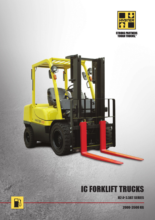
2000-3500 KGH2.0-3.5XT SERIES IC FORKLIFT TRUCKSn Hydrostatic Steer AxleMaximum durability, increased steer angle and steering control for easy manoeuvring and lower maintenance. New steer knob synchroniser system returns the steer knob to the same position when travelling in a straight line – improves operator comfort and control.n H yster ® Stability Mechanism ™The patented stability system reduces truck sway during turns, improving lateral stability. This innovative design allows for confident travel over uneven surfaces.n Engine CoverT he tough steel engine cover is hinged at the rear, offering excellent service access to the engine compartment.Each of these advancements demonstratesHyster’s commitment to be a strong partner and provide the toughest trucks for even the most challenging applications.HYSTER ®2.0-3.5XT SERIES FEATURESnI ntegral SideshiftThe optional Hyster-designed integral sideshift provides excellent visibility and affords greater capacities than carriage-mounted sideshifts.nH eavy-Duty Drive AxleThe full floating drive axle enhances dependability and reliability for a longer service life. Hyster premium self-adjusting brakes provide excellent inching and stopping power.nR emovable Floor PlateOne piece, steel floor plate removes for easy service access. A thick moulded rubber mat reduces noise and vibration.n Advanced Dash DisplayAmonochrome LCD displays all status – mounted on the steer column for easy operator viewing.nH assle-Free HydraulicsIn-tank hydraulic filter for cleaner fluid, longer life componentry.n Steer ColumnThe steering column is offset to the left and the standard synchronous steering function returns the spinner knob to the same position when driving ahead to give a consistent and comfortable driving position.n Hyster ® Vista ™ MastThe new range of Vista™ masts are wider for improved forward visibility. The masts are trunnion mounted for less wear and easier maintenance.EQUIPMENT AND WEIGHT:Weights (line 2.1) are based on the following specifi cations: Complete truck with 3000mm TOF 2-stage limited free lift mast, with standard hook type carriage, 1070mm forks with manual hydraulics, overhead guard and standard pneumatic shaped solid drive and steer tyres.Specification data is based on VDI 2198.D I S T I N G U I S H I N G M A R K1.1 Manufacturer (abbreviation) 1.2 Manufacturer’s type designation Model Engine / transmission1.3 Drive: electric (battery or mains), diesel, petrol, fuel gas1.4 Operator type: hand, pedestrian, standing, seated, order-picker 1.5 Rated capacity/rated load Q (t)1.6 Load centre distancec (mm)1.8 Load distance, centre of drive axle to fork x (mm)1.9 Wheelbasey (mm)5.1 Travel speed, laden/unladen km/h 5.1.1 Travel speed, laden/unladen, backwards km/h 5.2 Lift speed, laden/unladen m/s 5.3 Lowering speed, laden/unladen m/s 5.5 Drawbar pull, laden/unladen † N 5.7 Gradeability, laden/unladen †† % 5.10 Service brake 7.1 Engine manufacturer/type 7.2 Engine power according to ISO 1585 6 kW 7.3 Rated speed min–1 7.3.1 Torque at 1/min Nm/min–1 7.4 Number of cylinders/displacement (-)/cm 3 7.5 Fuel consumption according to MIL 268C cycle l/h or kg/h 7.1 Battery voltage/nominal capacity S (V)/(Ah) 8.1 Type of drive unit 8.11 Service brake 8.12 Parking brake 10.1 Operating pressure for attachments bar 10.2 Oil volume for attachments ³ l/min 10.3 Hydraulic oil tank, capacity l 10.4 Fuel tank, capacity l 10.7 Sound pressure level at the driver’s seat < J dB (A)10.8Towing coupling, type DIN3.1 Tyres: L = pneumatic, V = solid, SE = pneumatic-shaped solid 3.2 Tyre size, front (standard tread)3.2.1 Tyre size, front (dueal tread) 3.3 Tyre size, rear3.5 Wheels, number front/rear (x = driven wheels)3.6 Tread, front (standard/dueal tread) b 10 (mm) 3.7 Tread, rearb 11 (mm)4.1 Tilt of mast/fork carriage forward/backward a /b (°)4.2 Height, mast lowered h 1 (mm) 4.3 Free lift ¶ h 2 (mm) 4.4 Lift ¶ h 3 (mm) 4.5 Height, mast extended è h 4 (mm) 4.7 Height of overhead guard (cabin) h 6 (mm) 4.8 Seat height relating to SIP/stand height ¢ h 7 (mm) 4.12 Coupling height h 10 (mm) 4.19 Overall length l 1 (mm) 4.20 Length to face of forks l 2 (mm) 4.21 Overall width G b 1/b 2 (mm) 4.22 Fork dimensions ISO 2331 s/e/l (mm) 4.23 Fork carriage ISO 2328, class/type A, B 4.24 Fork carriage width l b 3 (mm) 4.31 Ground clearance, laden, below mast m 1 (mm) 4.32 Ground clearance, centre of wheelbase m 2 (mm) 4.34.1 Aisle width for pallets 1000 × 1200 crossways u Ast (mm) 4.34.2 Aisle width for pallets 800 × 1200 crossways u Ast (mm) 4.35 Turning radius W a (mm) 4.41 90° intersecting aisle (with pallet L = 1000mm x W = 1200mm) (mm) 4.42 Step height (from ground to running board) (mm) 4.43 Step height (between intermediate steps and floor) (mm)P E R F O R M A N C E D A T A C O M B U S T I O N E N G I N E A D D I T I O N A L D A T AD I ME N S I O N ST Y R E S /C H A S S I SH2.0XT - AD H2.5XT - ADH3.0XT - BD H3.5XT - BD Yanmar 2.6LYanmar 2.6LYanmar 3.3LYanmar 3.3L Basic Basic Basic Basic Powershift Powershift Powershift Powershift 1-speed 1-speed 1-speed 1-speed Diesel Diesel Diesel Diesel Seated Seated Seated Seated 2 2.5 3 3.5 500 500 500 500 480 480 505 520 1625162517001700HYSTER HYSTERHYSTERHYSTER3480 3610 3810 3940 4350 4435 4940 5055 4755 725 5500 810 6525 825 7450 990 1565 1915 1515 2295 1780 2570 1880 3060 L L L SE 7.00-12-12PR 7.00-12-12PR 28x9-15-12PR 28x9-15 SOLID 7.00-12-12PR 7.00-12-12PR 7.00-12-12PR 6.00-15 SOLID 6.0-9-10PR 6.0-9-10PR 6.50-10-10PR 6.50-10 SOLID 2x 2 2x 2 2x 2 2x 2 970 1405 970 1405 1010 1405 1010 1330 1000 1000 1000 1000 6 10 6 10 6 10 6 10 1995 1995 2060 2140 155 155 160 165 3050 3050 3055 3060 4120 4120 4125 4125 2130 2130 2150 2150 990 990 1010 1010 350 350 350 350 3470 3685 3835 3905 2550 2615 2765 2835 1160 1590 1160 1590 1230 1590 1230 1490 40 / 122 / 1070 40 / 122 / 1070 45 / 122 / 1070 50 / 150 / 1070 II II III III 1020 1020 1070 1070 120 120 140 140 190 190 210 210 3845 3905 4050 4115 3645 3705 3850 3915 2185 2245 2365 2415 2025 2090 2195 2235 410 410 430 430 290 290 290 29017.5 19 17.5 19 17.5 18.5 17.5 18 17.5 19 17.5 19 17.5 18.5 17.5 18 620 670 610 670 560 570 475 490 495 520 495 520 495 520 495 520 16700 16700 22300 20400 26 26 22 23 27 22 21 19 Hydraulic Hydraulic Hydraulic Hydraulic Yanmar/4TNE92 Yanmar/4TNE92 Yanmar/4TNE98 Yanmar/4TNE98 29 29 43 43 2050 2050 2300 2300 143 1400 143 1400 189 1600 189 1600 4 2659 4 2659 4 3319 4 3319 2.7 2.8 3.4 3.6 12 64 12 64 12 64 12 64 AutomaticAutomatic Automatic Automatic Hydraulic Hydraulic Hydraulic Hydraulic Hand Hand Hand Hand 181 181 181 157 71 71 82 71 38.0 38.0 40.0 40.0 69.0 69.0 69.0 69.0 - - - - HookHookHookHookEQUIPMENT AND WEIGHT:Weights (line 2.1) are based on the following specifi cations: Complete truck with 3000mm TOF 2-stage limited free lift mast, with standard hook type carriage, 1070mm forks with manual hydraulics, overhead guard and standard pneumatic shaped solid drive and steer tyres.Specification data is based on VDI 2198.5.1 Travel speed, laden/unladen km/h 5.1.1 Travel speed, laden/unladen, backwards km/h 5.2 Lift speed, laden/unladen m/s 5.3 Lowering speed, laden/unladen m/s 5.5 Drawbar pull, laden/unladen † N 5.7 Gradeability, laden/unladen †† % 5.10 Service brake 7.1 Engine manufacturer/type 7.2 Engine power according to ISO 1585 6 kW 7.3 Rated speed min–1 7.3.1 Torque at 1/min Nm/min–1 7.4 Number of cylinders/displacement (-)/cm 3 7.5 Fuel consumption according to MIL 268C cycle l/h or kg/h 7.1 Battery voltage/nominal capacity S (V)/(Ah) 8.1 Type of drive unit 8.11 Service brake 8.12 Parking brake 10.1 Operating pressure for attachments bar 10.2 Oil volume for attachments ³ l/min 10.3 Hydraulic oil tank, capacity l 10.4 Fuel tank, capacity l 10.7 Sound pressure level at the driver’s seat < J dB (A)10.8 Towing coupling, type DIN3.1 Tyres: L = pneumatic, V = solid, SE = pneumatic-shaped solid 3.2 Tyre size, front (standard tread)3.2.1 Tyre size, front (dueal tread) 3.3 Tyre size, rear3.5 Wheels, number front/rear (x = driven wheels)3.6 Tread, front (standard/dueal tread) b 10 (mm) 3.7 Tread, rearb 11 (mm)4.1 Tilt of mast/fork carriage forward/backward a /b (°)4.2 Height, mast lowered h 1 (mm) 4.3 Free lift ¶ h 2 (mm) 4.4 Lift ¶ h 3 (mm) 4.5 Height, mast extended è h 4 (mm) 4.7 Height of overhead guard (cabin) h 6 (mm) 4.8 Seat height relating to SIP/stand height ¢ h 7 (mm) 4.12 Coupling height h 10 (mm) 4.19 Overall length l 1 (mm) 4.20 Length to face of forks l 2 (mm) 4.21 Overall width G b 1/b 2 (mm) 4.22 Fork dimensions ISO 2331 s/e/l (mm) 4.23 Fork carriage ISO 2328, class/type A, B 4.24 Fork carriage width l b 3 (mm) 4.31 Ground clearance, laden, below mast m 1 (mm) 4.32 Ground clearance, centre of wheelbase m 2 (mm) 4.34.1 Aisle width for pallets 1000 × 1200 crossways u Ast (mm) 4.34.2 Aisle width for pallets 800 × 1200 crossways u Ast (mm) 4.35 Turning radius W a (mm) 4.41 90° intersecting aisle (with pallet L = 1000mm x W = 1200mm) (mm) 4.42 Step height (from ground to running board) (mm) 4.43 Step height (between intermediate steps and floor) (mm)P E R F O R M A N C E D A T AC O M B U S T I O N E N G I N EA D D I T I O N A L D A T AD I ME N S I O N ST Y R E S /C H A S S I SH2.0XT - AL H2.5XT - AL H3.0XT - BL K21 2.1L K21 2.1L K25 2.5L Basic Basic Basic Powershift Powershift Powershift 1-speed 1-speed 1-speed L PG L PG L PG Seated Seated Seated 2.0 2.5 3.0 500 500 500 465 465 490 1625 1625 1700 HYSTER HYSTER HYSTER3390 3520 3720 3850 4260 4345 4730 660 5455 765 6335 925 1530 1850 1470 2250 1635 2670 L L L 7.00-12-12PR 7.00-12-12PR 28x9-15-12PR 7.00-12-12PR 7.00-12-12PR 7.00-12-12PR 6.0-9-10PR 6.0-9-10PR 6.50-10-10PR 2x 2 2x 2 2x 2 970 1405 970 1405 1010 1405 1000 1000 1000 6 10 6 10 6 10 1995 1995 2060 155 155 160 3050 3050 3055 4120 4120 4125 2130 2130 2150 990 990 1010 350 350 350 3470 3685 3835 2550 2615 2765 1160 1590 1160 1590 1230 1590 40 / 122 / 1070 40 / 122 / 1070 45 / 122 / 1070 II II III 1020 1020 1070 120 120 140 190 190 210 3845 3905 4050 3645 3705 3850 2185 2245 2365 2025 2090 2195 410 410 430 290 290 29018 19.5 18 19.5 19 20 18 19.5 18 19.5 19 20 525 580 515 580 515 575 495 520 495 520 495 520 18900 18900 19000 30 26 26 22 24 22 Hydraulic Hydraulic Hydraulic GCT/K21 GCT/K21 GCT/K25 31 31 34 2250 2250 2100 144 1600 144 1600 173 1600 4 2065 4 2065 4 2488 1.8 1.9 2.3 12 28 12 28 12 28 AutomaticAutomatic Automatic Hydraulic Hydraulic Hydraulic Hand Hand Hand 181 181 181 65 65 74 38.0 38.0 40.0 - --- 78 78 80 HookHookHookEQUIPMENT AND WEIGHT:Weights (line 2.1) are based on the following specifi cations: Complete truck with 3000mm TOF 2-stage limited free lift mast, with standard hook type carriage, 1070mm forks with manual hydraulics, overhead guard and standard pneumatic shaped solid drive and steer tyres.Specification data is based on VDI 2198.D I S T I N G U I S H I N G M A R K1.1 Manufacturer (abbreviation) 1.2 Manufacturer’s type designation Model Engine / transmission1.3 Drive: electric (battery or mains), diesel, petrol, fuel gas1.4 Operator type: hand, pedestrian, standing, seated, order-picker 1.5 Rated capacity/rated load Q (t)1.6 Load centre distancec (mm)1.8 Load distance, centre of drive axle to fork x (mm)1.9 Wheelbasey (mm)5.1 Travel speed, laden/unladen km/h 5.1.1 Travel speed, laden/unladen, backwards km/h 5.2 Lift speed, laden/unladen m/s 5.3 Lowering speed, laden/unladen m/s 5.5 Drawbar pull, laden/unladen † N 5.7 Gradeability, laden/unladen †† % 5.10 Service brake 7.1 Engine manufacturer/type 7.2 Engine power according to ISO 1585 6 kW 7.3 Rated speed min–1 7.3.1 Torque at 1/min Nm/min–1 7.4 Number of cylinders/displacement (-)/cm 37.5 Fuel consumption according to MIL 268C cycle l/h or kg/h 7.1 Battery voltage/nominal capacity S (V)/(Ah) 8.1 Type of drive unit8.11 Service brake8.12 Parking brake 10.1 Operating pressure for attachments bar 10.2 Oil volume for attachments ³ l/min 10.3 Hydraulic oil tank, capacity l 10.4 Fuel tank, capacity l 10.7 Sound pressure level at the driver’s seat < J dB (A)10.8Towing coupling, type DIN3.1 Tyres: L = pneumatic, V = solid, SE = pneumatic-shaped solid 3.2 Tyre size, front (standard tread)3.2.1 Tyre size, front (dueal tread) 3.3 Tyre size, rear3.5 Wheels, number front/rear (x = driven wheels)3.6 Tread, front (standard/dueal tread) b 10 (mm) 3.7 Tread, rearb 11 (mm)4.1 Tilt of mast/fork carriage forward/backward a /b (°)4.2 Height, mast lowered h 1 (mm) 4.3 Free lift ¶ h 2 (mm) 4.4 Lift ¶ h 3 (mm) 4.5 Height, mast extended è h 4 (mm) 4.7 Height of overhead guard (cabin) h 6 (mm) 4.8 Seat height relating to SIP/stand height ¢ h 7 (mm) 4.12 Coupling height h 10 (mm) 4.19 Overall length l 1 (mm) 4.20 Length to face of forks l 2 (mm) 4.21 Overall width G b 1/b 2 (mm) 4.22 Fork dimensions ISO 2331 s/e/l (mm) 4.23 Fork carriage ISO 2328, class/type A, B 4.24 Fork carriage width l b 3 (mm) 4.31 Ground clearance, laden, below mast m 1 (mm) 4.32 Ground clearance, centre of wheelbase m 2 (mm) 4.34.1 Aisle width for pallets 1000 × 1200 crossways u Ast (mm) 4.34.2 Aisle width for pallets 800 × 1200 crossways u Ast (mm) 4.35 Turning radius W a (mm) 4.41 90° intersecting aisle (with pallet L = 1000mm x W = 1200mm) (mm) 4.42 Step height (from ground to running board) (mm) 4.43 Step height (between intermediate steps and floor) (mm)P E R F O R M A N C E D A T A C O M B U S T I O N E N G I N E A D D I T I O N A L D A T AD I ME N S I O N ST Y R E S /C H A S S I SH2.0XT - AG H2.5XT - AG H3.0XT - BG K21 2.1LK21 2.1LK25 2.5L Basic Basic Basic Powershift Powershift Powershift 1-speed 1-speed 1-speed Petrol Petrol Petrol Seated Seated Seated 2.0 2.5 3.0 500 500 500 465 465 490 1625162517003390 3520 3720 3850 4260 4345 4730 660 5455 765 6335 925 1530 1850 1470 2250 1635 2670 L L L 7.00-12-12PR 7.00-12-12PR 28x9-15-12PR 7.00-12-12PR 7.00-12-12PR 7.00-12-12PR 6.0-9-10PR 6.0-9-10PR 6.50-10-10PR 2x 2 2x 2 2x 2 970 1405 970 1405 1010 1405 1000 1000 1000 6 10 6 10 6 10 1995 1995 2060 155 155 160 3050 3050 3055 4120 4120 4125 2130 2130 2150 990 990 1010 350 350 350 3470 3685 3835 2550 2615 2765 1160 1590 1160 1590 1230 1590 40 / 122 / 1070 40 / 122 / 1070 45 / 122 / 1070 II II III 1020 1020 1070 120 120 140 190 190 210 3845 3905 4050 3645 3705 3850 2185 2245 2365 2025 2090 2195 410 410 430 290 290 29018 19.5 18 19.5 19 20 18 19.5 18 19.5 19 20 525 580 515 580 515 575 495 520 495 520 495 520 18900 18900 19000 30 26 26 22 24 22 Hydraulic Hydraulic Hydraulic GCT/K21 GCT/K21 GCT/K25 31 31 34 2250 2250 2100 144 1600 144 1600 173 16004 2065 4 2065 4 2488 2.7 2.9 3.3 12 28 12 28 12 28 Automatic Automatic Automatic Hydraulic Hydraulic Hydraulic Hand Hand Hand 181 181 181 65 65 74 38.0 38.0 40.0 69.0 69.0 69.0 78 78 80 HookHookHookHYSTER HYSTERHYSTEREQUIPMENT AND WEIGHT:Weights (line 2.1) are based on the following specifi cations: Complete truck with 3000mm TOF 2-stage limited free lift mast, with standard hook type carriage, 1070mm forks with manual hydraulics, overhead guard and standard pneumatic shaped solid drive and steer tyres.Specification data is based on VDI 2198.5.1 Travel speed, laden/unladen km/h 5.1.1 Travel speed, laden/unladen, backwards km/h 5.2 Lift speed, laden/unladen m/s 5.3 Lowering speed, laden/unladen m/s 5.5 Drawbar pull, laden/unladen † N 5.7 Gradeability, laden/unladen †† % 5.10 Service brake 7.1 Engine manufacturer/type 7.2 Engine power according to ISO 1585 6 kW 7.3 Rated speed min–1 7.3.1 Torque at 1/min Nm/min–1 7.4 Number of cylinders/displacement (-)/cm 37.5 Fuel consumption according to MIL 268C cycle l/h or kg/h 7.1 Battery voltage/nominal capacity S (V)/(Ah) 8.1 Type of drive unit8.11 Service brake8.12 Parking brake 10.1 Operating pressure for attachments bar 10.2 Oil volume for attachments ³ l/min 10.3 Hydraulic oil tank, capacity l 10.4 Fuel tank, capacity l 10.7 Sound pressure level at the driver’s seat < J dB (A)10.8Towing coupling, type DIN3.1 Tyres: L = pneumatic, V = solid, SE = pneumatic-shaped solid 3.2 Tyre size, front (standard tread)3.2.1 Tyre size, front (dueal tread) 3.3 Tyre size, rear3.5 Wheels, number front/rear (x = driven wheels)3.6 Tread, front (standard/dueal tread) b 10 (mm) 3.7 Tread, rearb 11 (mm)4.1 Tilt of mast/fork carriage forward/backward a /b (°)4.2 Height, mast lowered h 1 (mm) 4.3 Free lift ¶ h 2 (mm) 4.4 Lift ¶ h 3 (mm) 4.5 Height, mast extended è h 4 (mm) 4.7 Height of overhead guard (cabin) h 6 (mm) 4.8 Seat height relating to SIP/stand height ¢ h 7 (mm) 4.12 Coupling height h 10 (mm) 4.19 Overall length l 1 (mm) 4.20 Length to face of forks l 2 (mm) 4.21 Overall width G b 1/b 2 (mm) 4.22 Fork dimensions ISO 2331 s/e/l (mm) 4.23 Fork carriage ISO 2328, class/type A, B 4.24 Fork carriage width l b 3 (mm) 4.31 Ground clearance, laden, below mast m 1 (mm) 4.32 Ground clearance, centre of wheelbase m 2 (mm) 4.34.1 Aisle width for pallets 1000 × 1200 crossways u Ast (mm) 4.34.2 Aisle width for pallets 800 × 1200 crossways u Ast (mm) 4.35 Turning radius W a (mm) 4.41 90° intersecting aisle (with pallet L = 1000mm x W = 1200mm) (mm) 4.42 Step height (from ground to running board) (mm) 4.43 Step height (between intermediate steps and floor) (mm)P E R F O R M A N C E D A T A C O M B U S T I O N E N G I N E A D D I T I O N A L D A T AD I ME N S I O N ST Y R E S /C H A S S I SH2.0XT - AT H2.5XT - ATH3.0XT - BT K21 2.1LK21 2.1LK25 2.5L Basic Basic Basic Powershift Powershift Powershift 1-speed 1-speed 1-speed Dual fuelDual fuelDual fuel Seated Seated Seated 2.0 2.5 3.0 500 500 500 465 465 490 1625162517003390 3520 3720 3850 4260 4345 4730 660 5455 765 6335 925 1530 1850 1470 2250 1635 2670 L L L 7.00-12-12PR 7.00-12-12PR 28x9-15-12PR 7.00-12-12PR 7.00-12-12PR 7.00-12-12PR 6.0-9-10PR 6.0-9-10PR 6.50-10-10PR 2x 2 2x 2 2x 2 970 1405 970 1405 1010 1405 1000 1000 1000 6 10 6 10 6 10 1995 1995 2060 155 155 160 3050 3050 3055 4120 4120 4125 2130 2130 2150 990 990 1010 350 350 350 3470 3685 3835 2550 2615 2765 1160 1590 1160 1590 1230 1590 40 / 122 / 1070 40 / 122 / 1070 45 / 122 / 1070 II II III 1020 1020 1070 120 120 140 190 190 210 3845 3905 4050 3645 3705 3850 2185 2245 2365 2025 2090 2195 410 410 430 290 290 29018 19.5 18 19.5 19 20 18 19.5 18 19.5 19 20 525 580 515 580 515 575 495 520 495 520 495 520 18900 18900 19000 30 26 26 22 24 22 Hydraulic Hydraulic Hydraulic GCT/K21 GCT/K21 GCT/K25 31 31 34 2250 2250 2100 144 1600 144 1600 173 16004 2065 4 2065 4 2488 2.7 1.8 2.9 1.9 3.3 2.3 12 28 12 28 12 28 Automatic Automatic Automatic Hydraulic Hydraulic Hydraulic Hand Hand Hand 181 181 181 65 65 74 38.0 38.0 40.0 69.0 69.0 69.0 78 78 80 HookHookHookHYSTER HYSTERHYSTERNOTESValues shown are for standard equipment. When using non-standard equipment, these values may change. Please contact your Hyster dealer for information.The rated capacities shown are for masts in a vertical position on trucks equipped with standard or sideshift carriage, and nominal length forks.Masts above the maximum fork heights shown in the mast table are classified as high lift, and depending on the tyre/tread configuration may require reduced capacity, restricted back tilt or wide tread.Specification data based on standard carriage, load backrest and 1070mm forks.2-stage Full Free Lift2-stage Limited Free Lift3-stage Full Free LiftMaximum fork height (mm)Back tilt Overalllowered height (mm)Overall Extended height (mm)v Overall Extended height (mm)♦Free lift (top of forks) (mm) v2140229023902490269028402940309031902190234024402590279020402110219023402440259026902790294010 3060 38454125 165 10 3360 4145 4425 165 10 3560 4345 4625 165 10 3760 4545 4825 165 10 4060 4845 5125 165 6 4360 5145 5425 165 6 4560 5345 5625 165 6 4860 5645 5925 165 6 50605845612516510 3085 3850 4150 1070 10 3385 4150 4450 1220 10 3585 4350 4650 1320 10 3835 4600 4900 1470 6 4185 4950 5250 1670 6 4125 4970 5190 920 6 4335 5180 5400 990 6 4575 5420 5640 1070 6 4825 5670 5890 1220 6 5025 5870 6090 1320 6 5325 6170 6390 1470 6 5525 6370 6590 1570 6 5725 6570 6790 1670 66025 6870 7090 1775H3.0-3.5XT - Capacity Chart in kgMaximum fork height (mm)Maximum fork height (mm)Maximumfork height (mm)Maximumfork height (mm)2-stage Full Free Lift2-stageLimited Free Lift30503350355037504050435045504850505030003390359038404190413543454585484050355335553556856035306033603560376040604360456048605060308533853585383541854130434045804830503053305530573060303055335535553755405543554555485550553080338035803830418041254335457547055025532555255725602530603360356037604060436045604860506030853385358538354185413043404580483050305330553057306030500 LC 600 LC 700 LC 3000 2920 2680 3000 2920 2680 3000 2910 2670 3000 2910 2670 3000 2900 2660 3000 2890 2650 2950 2860 2610 2880 2770 2540 2830 2720 2490 3000 2920 2670 3000 2910 2670 3000 2900 2660 3000 2900 2660 3000 2890 2650 3000 2890 2650 3000 2890 2650 2950 2830 2610 2930 2810 2560 2860 2720 2490 2770 2630 2430 2720 2590 2380 2680 2520 2310 2590 2450 2240500 LC 600 LC 700 LC 3500 3390 3110 3500 3380 3100 3500 3380 3100 3500 3380 3100 3500 3360 3090 3500 3360 3080 3450 3310 3040 3380 3240 2970 3330 3170 2930 3500 3380 3100 3500 3380 3100 3500 3370 3090 3500 3370 3090 3500 3350 3080 3500 3340 3070 3500 3340 3060 3450 3290 3020 3380 3220 2950 3330 3150 2900 3240 3080 2810 3020 2990 2770 2790 2790 2720 2470 2490 2470500 LC 600 LC 700 LC3000 2800 2580 3000 2800 2570 3000 2790 2570 3000 2790 2560 3000 2780 2550 3000 2770 2550 2950 2720 2520 2880 2650 2450 2830 2610 2400 3000 2800 2570 3000 2790 2570 3000 2790 2560 3000 2780 2560 3000 2770 2550 3000 2780 2550 3000 2770 2550 2950 2720 2490 2930 2700 2470 2860 2610 2400 2770 2540 2340 2720 2490 2290 2650 2430 2220 2560 2340 2150500 LC 600 LC 700 LC 3500 3250 2990 3500 3240 2980 3500 3240 2980 3500 3240 2980 3500 3220 2970 3500 3220 2960 3450 3170 2930 3380 3110 2860 3330 3060 2810 3500 3250 2990 3500 3240 2980 3500 3240 2980 3500 3230 2970 3500 3220 2960 3500 3230 2970 3500 3220 2960 3450 3170 2900 3380 3110 2860 3330 3060 2810 3240 2970 2720 3020 2900 2680 2810 2790 2630 2490 2490 24703-stageFull Free LiftPneumatic Shaped Solid TyresH3.0XTH3.5XTH3.0XTH3.5XTWithout sideshiftWithout sideshiftWith integral sideshiftWith integral sideshift10l l b b b xWa100mma 2100mma 2Asth h h h sQcαll y l h h h m m βb x40003500300025002000150010005000250500750100012501500H3.5XT H3.0XT H2.5XT H2.0XT40003500300025002000150010005000250500750100012501500H3.5XTH3.0XT H2.5XT H2.0XTTRUCK DIMENSIONS= Centre of gravity of unladen truck Ast = W a + x + l 6 + a (see lines 4.34.1 & 4.34.2) a = Minimum operating clearance(VDI standard = 200 mm BITA recommendation = 300 mm) l 6= Load lengthRATED CAPACITIESLoad centreDistance from front of forks to centre of gravity of load.Rated loadBased on vertical masts up to 4310 mm.Load centre (mm)Standard CarriageIntegral Sideshift CarriageLoad centre (mm)R a t e d l o a d (k g )R a t e d l o a d (k g )NOTE:Specifications are affected by the condition of the vehicle and how it is equipped, as well as the nature and condition of the operating area. Inform your dealer of the nature and condition of the intended operating area when purchasing your Hyster T ruck.GStandard / wide / dual ¶Top of forksè add 32mm with load backrest¢ Full suspension seat in depressed position l Without load backrest, add 32mm with load backrestuStacking aisle width (lines 4.34 & 4.34.1 &4.34.2) are based on the V .D.I. standard calculation as shown on illustration. The British Industrial Truck Association recommends the addition of 100 mm to the total clearance (dimension a) for extra operating margin at the rear of the truck 6Engine power entries are shown as net values ††at 1.6 km/h†at 4.8km/h. Gradeability figures are provided for comparison of tractive performance, but are not intended toendorse the operation of the vehicle on the stated inclines. Follow instructions in the operating manual regarding operation on inclines.q to 15m (per VDI 2198 December 2012)SBattery ampere hour (Ah) nominal capacity ratings are estimated.³ Variable< With and without cab.♦Noise levels are reduced by 3dB(A) with ECO-eLo mode engaged.JLpaz, Measured according to the test cycles and based on the weighting values contained in EN12053¬Lwaz, Measured according to the test cycles and based on the weighting values contained in EN12053.MAST TABLES:v without load backrest♦ with load backrestNOTICECare must be exercised when handling elevated loads. When the carriage and/or load is elevated, truck stability is reduced. It is important that the mast tilt in either direction is kept to a minimum when loads are elevated.Operators must be trained and must read, understand and follow the instructions contained in the Operating Manual.All values are nominal values and they are subject to tolerances. For further information, please contact the manufacturer.Hyster products are subject to change without notice.Lift trucks illustrated may feature optional equipment. Values may vary with alternative configurations.STANDARD FEATURES & OPTIONSSTANDARD EQUIPMENTComplete truck equipped with:n2-Stage limited free lift Vista™ mast with lift height of 3035mmn Hook-type carriage with 1070mm high load backrest (LBR) n1070mm long forksn Y anmar 2.6L Diesel or GCT K21 Petrol / LPG engine (H2.0-2.5XT)n Y anmar 3.3L Diesel or GCT K25 Petrol / LPG engine (H3.0-3.5XT)n Powershift transmission+ Mechanical inching+ Neutral start function+ Heavy duty clutch platesn Directional control levern Single pedal inch braken N on-suspension vinyl seat (not available with seat side hydraulic control Mini levers)n Pneumatic tyresn 2 Hydraulic leversn Standard integrated dash display+ Monochrome LCD panel– Real time clock– Hour meter– Fasten seatbelt– F uel level with low fuel warning buzzer (Petrol & Dieselfuel only)+ Service Indicators– Service required– Coolant temperature with high temp warning buzzer– Alternator with warning buzzer– Transmission oil temperature with warning buzzer– Engine oil pressure with low pressure warning buzzer– Glow lamp (Diesel fuel engine only)– Error messagen Key starting with anti-restart functionn Hydrostatic steering with steer knob synchronisern Adjustable vinyl seatn Electric Hornn Infinitely adjustable steering columnn Rubber floor matn High air intaken Counterweight exhaustn Integral tie downsn Operator’s seat beltn Serpentine radiatorn Hyster Stability Mechanism™ (HSM)n Swing down LPG tank bracket Cabinn S tandard Over Head Guard (OHG) with rain gutter and cup holdern 78 dB(A) standard noise level for Petrol/LPG engine optionn 83.5 dB(A) standard noise level for Diesel engine optionn 12 months / 2000 hours manufacturer’s warrantyn Operator’s manualn Compliance with ISO 3691 / JIS D 6202OPTIONAL EQUIPMENTMastsn 2-Stage limited free lift Vista™ masts with up to 4855mm lift heightn 2-Stage full free lift Vista™ masts with up to 3390mm lift height n 3-Stage full free lift Vista™ masts with up to 6035mm lift heightCarriagesn Integral side shift (ISS) carriageHydraulic Valve and Leversn 3-function cowl mounted hydraulic levers with or without interlock for clampingn 4-function cowl mounted hydraulic levers with or without interlock for clampingForksn Fork lengths are available from 1070mm to 1520mmControlsn S eparate Inch brake and brake pedals for sure handling on steep inclinesn Mini levers with adjustable armrestDash Displayn Speedometer with speed alarm and warning buzzern Travel speed limitern Digital load weight displaySeatsn Full suspension vinyl seatBrakesn Heavy duty drum brakesEnvironmentaln Vertical exhaustn 2-way catalytic mufflern Spark arrestor mufflern High capacity radiatorn High mount pre-cleanern Dual element air filter for Petrol/LPG engine optionn Tandem air filter for Diesel engine optionOthern H ydraulic cut-out seat interlock (prevents travel when operator seatbelt is not used)n L ight Kit consisting of 2 Halogen front head lights, 2 front turn indicators plus rear combination (turn indicators, reversingand brake) lights and reverse alarmn 2 rear vision mirrorsn Rear work light (switch or reverse operated)。
西门子 NXGPro+ 控制系统手册_操作手册说明书
3.4
单元通讯的协议 ............................................................................................................ 36
3.5
NXGpro+ 高级安全 .......................................................................................................37
3.2
功率拓扑 ......................................................................................................................34
3.3
控制系统概述 ...............................................................................................................35
NXGPro+ 控制系统手册
NXGPro+ 控制系统手册
操作手册
AC
A5E50491925J
安全性信息
1
安全注意事项
2
控制系统简介
3
NXGPro+ 控制系统简介
4
硬件用户界面说明
5
参数配置/地址
6
运行控制系统
7
高级的操作功能
8
软件用户界面
9
运行软件
10
故障和报警检修
11
【商品说明书】630kw永磁直驱电动机说明书
630kw永磁直驱电动机说明书1️⃣ 产品概述630kw永磁直驱电动机是一款高性能、高效率的电动机产品,专为需要大功率、低维护和高可靠性的工业应用设计。
该电动机采用先进的永磁体材料,实现了直接驱动,无需传统的减速机构,从而减少了能量损失和机械故障,提高了整体系统的运行效率。
2️⃣ 技术规格与特点2.1 技术规格额定功率:630千瓦(kW)额定电压:根据客户需求定制,通常为380V或400V额定频率:50Hz或60Hz额定转速:根据具体应用调整,通常在1500rpm至3000rpm之间效率:≥96%功率因数:≥0.952.2 主要特点高效节能:永磁体直接驱动,减少了能量传递过程中的损失,提高了能源利用效率。
低噪音与振动:结构紧凑,设计合理,有效降低了运行时的噪音和振动。
高可靠性:采用高质量材料和先进制造工艺,确保电动机在恶劣环境下仍能稳定运行。
易于维护:无减速机构,减少了维护工作量,降低了维护成本。
灵活定制:可根据客户需求提供不同功率、电压、频率和转速的定制服务。
3️⃣ 安装、调试与维护3.1 安装确保电动机安装基础平整、坚固,避免振动和位移。
根据电动机的尺寸和重量,选择合适的吊装工具和安装方法。
连接电缆时,确保电缆规格符合电动机要求,并正确连接相序。
3.2 调试在启动前,检查电动机的绝缘电阻、接线和接地情况。
逐步增加电压,观察电动机的启动电流、运行电流和温升情况。
调整负载,使电动机在额定负载下稳定运行,并检查其振动和噪音水平。
3.3 维护定期检查电动机的轴承、润滑系统和冷却系统,确保其正常运行。
清洁电动机外壳和散热片,避免灰尘和污垢影响散热效果。
定期检查电动机的绝缘电阻,及时发现并处理绝缘老化问题。
如发现电动机运行异常,应立即停机检查,并联系专业维修人员进行处理。
总结而言,630kw永磁直驱电动机以其卓越的性能、高效的能源利用和低维护成本,成为众多工业领域的理想选择。
通过正确安装、调试和维护,可以确保电动机长期稳定运行,为客户创造更大的价值。
LPZ系列底部挂载平行驱动包(标准负载)60HZ直驱电机产品说明书

851-528 Rev. BInstallation, Maintenance& Parts ManualTable of ContentsWarnings − General Safety 2. . . . . . . . . . . . . . . . . . . . Introduction 2. . . . . . . . . . . . . . . . . . . . . . . . . . . . . . . . Product Description 3. . . . . . . . . . . . . . . . . . . . . . . . . . Specifications 3. . . . . . . . . . . . . . . . . . . . . . . . . . . . . . . Gearmotors 6. . . . . . . . . . . . . . . . . . . . . . . . . . . . . . . 3200 Belt Speeds 6. . . . . . . . . . . . . . . . . . . . . . . . . . Installation 6. . . . . . . . . . . . . . . . . . . . . . . . . . . . . . . . . Required Tools 6. . . . . . . . . . . . . . . . . . . . . . . . . . . . Mounting 6. . . . . . . . . . . . . . . . . . . . . . . . . . . . . . . .Preventive Maintenance & Adjustment 8. . . . . . . . . . . Required Tools 8. . . . . . . . . . . . . . . . . . . . . . . . . . . . Timing Belt Tensioning 8. . . . . . . . . . . . . . . . . . . . . Timing Belt Replacement 8. . . . . . . . . . . . . . . . . . . Drive or Driven Pulley Replacement 9. . . . . . . . . . . Motor Replacement 9. . . . . . . . . . . . . . . . . . . . . . . . Service Parts 11. . . . . . . . . . . . . . . . . . . . . . . . . . . . . . Bottom Mount Drive Package 11. . . . . . . . . . . . . . . Gearmotors 13. . . . . . . . . . . . . . . . . . . . . . . . . . . . . . Return Policy 14. . . . . . . . . . . . . . . . . . . . . . . . . . . . . .IntroductionIMPORTANT: Some illustrations may show guardsremoved. Do NOT operate equipment without guards.Upon receipt of shipment:D Compare shipment with packing slip. Contact factoryregarding discrepancies.D Inspect packages for shipping damage. Contact carrierregarding damage.D Accessories may be shipped loose. See accessory in-structions for installation.Dorner 3200 Series conveyors are covered by patentnumbers 5156260, 5156261, 5203447, 5265714 andpatent applications in other countries.Dorner LPZ Series conveyors are covered by patentnumbers 5156260, 5156261, 5203447, 5265714,5875883 and patent applications in other countries.Dorner’s Limited Warranty applies.Dorner reserves the right to make changes at any timewithout notice or obligation.Dorner has convenient, pre−configured kits of Key ServiceParts for all conveyor products. These time saving kits are easyto order, designed for fast installation, and guarantee you willhave what you need when you need it. Key Parts and Kits aremarked in the Service Parts section of this manual with thePerformance Parts Kits logo .Warnings − General Safety3200 & LPZ Series Bottom Mount Parallel Drive Package for Standard Load 60 Hz Gearmotors IMPM851-528 Rev. B2Dorner Mfg. Corp.3200 & LPZ Series Bottom Mount Parallel Drive Package for Standard Load 60 Hz Gearmotors IMPMDorner Mfg. Corp.3851-528 Rev. BRefer to Figure 1 for typical components.A ConveyorB Mounting BracketC GearmotorD Timing Belt TensionerE CoverF Timing BeltG Drive Pulley HDriven PulleyTypical ComponentsFigure 1AF GCBH DSpecificationsGearmotor Mounting Package Models:Example:S = Standard Load Driven Pulley (see Table 2, 3 & 4)− = flat belt, A through J = cleated belt )Table 1: Gearmotor SpecificationsSingle PhaseThree Phase DCVariable Speed VFDVariable Speed Power/Gear Ratio hp (kW)hp (kW)hp (kW)hp (kW)5:1.08 (.06).17 (.13).12 (.09).17 (.13)10:1.17 (.13).17 (.13).25 (.19).17 (.13)20:1.33 (.25).38 (.28).25 (.19).38 (.28)30:1.33 (.25).38 (.28).25 (.19).38 (.28)60:1.33 (.25).38 (.28).33 (.25).38 (.28)180:1.33 (.25).38 (.28)N/A .38 (.28)Input Voltage 115 VAC 230 VAC 130 VDC 230 VAC Input Frequency60 Hz60 HzN/A10 to 60 HzProduct DescriptionTable 1: Gearmotor Specifications ContinuedSingle Phase Three Phase DCVariable Speed VFD Variable SpeedInput Current/Gear RatioFLA FLA FLA FLA 5:1 1.2 1.0 1.0 1.0 10:1 1.9 1.0 1.8 1.0 20:14 1.9 1.8 1.9 30:14 1.9 1.8 1.9 60:14 1.9 2.3 1.9 180:14 1.9N/A 1.9 Motor RPM1725172525001725Power/Ratio Totally Enclosed Fan Cooled Totally EnclosedNon−Ventilated Totally Enclosed Fan CooledTable 2: Belt Speeds for Fixed Speed Parallel Shaft 60 Hz GearmotorsStandard Load Gearmotors Belt Speed DrivePulley DrivenPart Number RPM In-lb N-m Ft/min M/min Pulley62M180PS4vpFn1022625.57.6 2.3161662M180PS4vpFn1022625.511.4 3.5241662M060PS4vpFn2923726.822.97.0161632M030PS4vpFn5814216.045.814.0161632M020PS4vpFn86788.868.620.9161632M020PS4vpFn86788.8103.031.4241632M010PS4vpFn17341 4.6137.341.9161632M010PS4vpFn17341 4.6171.652.3201632M010PS4vpFn17341 4.6205.962.8241632M005PS4vpFn34541 4.6274.683.7161632M005PS4vpFn34541 4.6343.2104.6201632M005PS4vpFn34541 4.6411.9125.62416(vp) = voltage and phase11 = 115 V, 1-phase23 = 208–230/460 V, 3-phaseTable 3: Belt Speeds for Variable Speed Parallel Shaft VFD Gearmotors Standard Load Gearmotors Belt Speed Drive Driven Part Number RPM In-lb N-m Ft/min M/min Pulley Pulley62M180PS4vpFn1022625.5 1.3−7.60.4−2.3161662M060PS4vpFn2923726.8 3.8−22.9 1.2−7.0161632M030PS4vpFn5814216.07.6−45.8 2.3−14.0161632M020PS4vpFn86788.811.5−68.6 3.5−20.9161632M020PS4vpFn86788.817.2−103.0 5.2−31.4241632M010PS4vpFn17341 4.622.9−137.37.0−41.9161632M010PS4vpFn17341 4.634.4−205.910.5−62.8241632M005PS4vpFn34541 4.645.9−274.614.0−83.71616Specifications3200 & LPZ Series Bottom Mount Parallel Drive Package for Standard Load 60 Hz Gearmotors IMPM851-528 Rev. B4Dorner Mfg. Corp.32M005PS4vpFn34541 4.657.3−343.217.5−104.6201632M005PS4vpFn34541 4.668.8−411.921.0−125.624163200 & LPZ Series Bottom Mount Parallel Drive Package for Standard Load 60 Hz Gearmotors IMPMDorner Mfg. Corp.5851-528 Rev. B3200 & LPZ Series Bottom Mount Parallel Drive Package for Standard Load 60 Hz Gearmotors IMPM851-528 Rev. B 6Dorner Mfg. Corp.Table 4: Belt Speeds for Variable Speed Parallel Shaft DC GearmotorsStandard Load GearmotorsBelt SpeedDrive PulleyDrivenPart Number RPM In-lb N-m Ft/minM/minPulley62M180PSD3DEN 1422625.5 1.3−11.10.4−3.4161662M180PSD3DEN 1422625.5 2.0−16.60.6−5.1241662M060PSD3DEN 4223726.8 4.0−33.2 1.2−10.1161662M030PSD3DEN 8314216.08.0−66.3 2.4−20.2161662M020PSD3DEN 125788.811.9−99.5 3.6−30.3161662M020PSD3DEN 125788.817.9−149.2 5.5−45.5241662M010PSD3DEN 25041 4.623.9−199.07.3−60.7161662M010PSD3DEN 25041 4.629.8−248.79.1−75.8201662M010PSD3DEN250414.635.8−298.510.9−91.02416NOTE: For belt speed other than those listed, contactfactory for details.InstallationRequired ToolsD Hex key wrenches:2 mm, 2.5 mm, 3 mm, 5 mm D Straight edge D Torque wrenchMountingInstallation Component ListE CoverF Timing BeltG Drive PulleyH Driven PulleyI Bottom Mount Drive Assembly J Cover Screws K KeyL M6 Socket Head Screws (4x)M M8 Socket Head Screws (2x)NT ensioner1.Typical components (Figure 2)Figure 2LHEFG K MIJ NNOTE: Cleated belt mounting package shown, flat beltmounting package similar.2.Locate drive output shaft (Q of Figure 3). Removetwo (2) M8 screws (P) and four (4) M6 screws (O)and discard.Figure 3QPOSpecifications3200 & LPZ Series Bottom Mount Parallel Drive Package for Standard Load 60 Hz Gearmotors IMPMDorner Mfg. Corp.7851-528 Rev. B3.Attach bottom mount drive assembly (B of Figure 4)with two (2) M8 screws (M) and four (4) M6 screws (L). Tighten M6 screws (L) to 146 in −lbs (16.5 N −m)and M8 screws (M) to 288 in −lbs (32.5 N −m).Figure 4BML4.Install key (K of Figure 5).Figure 5FG5.Wrap timing belt (F) around driven pulley (H) anddrive pulley (G). Install driven pulley (H) onto conveyor shaft.ing a straight edge (R of Figure 6), align drivenpulley (H) with drive pulley (G). Tighten driven pulley taper-lock screws (S of Figure 7).Figure 6HGFigure 77.Depending on conveyor belt travel (direction 1 or 2),locate timing belt tensioner (N of Figure 8) as shown.Tension timing belt to obtain 1/8” (3 mm) deflectionfor 6 lb (3 Kg) of force at timing belt mid-point (T).Tighten tensioner screw to 110 in-lb (12 Nm).Figure 8T8.Install cover (E of Figure 9) with four (4) screws (J).Tighten screws to 35 in-lb (4 Nm).Figure 9EJJInstallationRequired ToolsD Hex key wrenches:2 mm, 2.5 mm,3 mm, 5 mmD Adjustable wrench (for hexagon head screws)D Straight edgeD Torque wrenchTiming Belt Tensioning1.Remove four (4) screws (J of Figure 9) and removecover (E).2.Loosen tensioner (N of Figure 10).Figure 10N3.Depending on conveyor belt travel (direction 1 or 2),locate timing belt tensioner (N of Figure 8) as shown. Tension timing belt to obtain 1/8” (3 mm) deflection for 6 lb (3 Kg) of force at timing belt mid-point (T). Tighten tensioner screw to 110 in-lb(12 Nm).4.Install cover (E of Figure 9) with four (4) screws (J).Tighten screws to 35 in-lb (4 Nm).Timing Belt Replacement1.Remove four (4) screws (J of Figure 9) and removecover (E).2.Loosen tensioner (N of Figure 10).3.Remove timing belt (F of Figure 11).NOTE: If timing belt does not slide over pulley flange, loosen driven pulley taper-lock screws (S of Figure 7 & 11) and remove pulley with belt (F). For re-installation, see steps 5 and 6 on page 7.Figure 11FS4.Install new timing belt.5.Depending on conveyor belt travel (direction 1 or 2),locate timing belt tensioner (N of Figure 8) as shown. Tension timing belt to obtain 1/8” (3 mm) deflection for 6 lb (3 Kg) of force at timing belt mid-point (T). Tighten tensioner screw to 110 in-lb(12 Nm).6.Install cover (E of Figure 9) with four (4) screws (J).Tighten screws to 35 in-lb (4 Nm).Preventive Maintenance and Adjustment3200 & LPZ Series Bottom Mount Parallel Drive Package for Standard Load 60 Hz Gearmotors IMPM851-528 Rev. B8Dorner Mfg. Corp.3200 & LPZ Series Bottom Mount Parallel Drive Package for Standard Load 60 Hz Gearmotors IMPMDorner Mfg. Corp.9851-528 Rev. BDrive or Driven Pulley Replacementplete steps 1 through 3 of “Timing BeltReplacement” section on page 8.2.Remove taper-lock screws (S of Figure 12). Insert one(1) of taper lock screws (S of Figure 12) in remaining hole (U). Tighten screw (S) until pulley is loose.Remove pulley and taper hub assembly.Figure 12NOTE: If drive pulley (G of Figure 5) is replaced,wrap timing belt around drive pulley and complete step 3.plete steps 5 through 8 of “Installation” sectionbeginning on page 7.Motor Replacement1.For single phase motor, unplug power cord fromoutlet.2.For three phase and VFD variable speed motor:a .Loosen terminal box screws (V of Figure 13) andremove cover (W).Figure 13b .Record incoming wire colors on red, black andblue leads. Loosen wire nuts and remove incoming wires.c .Loosen cord grip and remove cord.Preventive Maintenance and Adjustment3200 & LPZ Series Bottom Mount Parallel Drive Package for Standard Load 60 Hz Gearmotors IMPM851-528 Rev. B 10Dorner Mfg. Corp.3.For DC variable speed motor, unplug motor cord atdisconnect (X of Figure 14).Figure 144.Remove the drive pulley see steps 1 and 2 of “Driveor Driven Pulley Replacement” section on page 9.5.Remove four (4) screws (J of Figure 15). Detach motor (C) from the mounting plate (B). Retain motor output shaft key (K).Figure 15CBKJ6.Install new motor using the four (4) mountingscrews (J of Figure 15).7.Re −install the drive pulley reverse step 2 of “Driveor Driven Pulley Replacement” section on page plete steps 5 through 8 of “Installation” section beginning on page 7.9.Replace wiring:D For a single phase motor, reverse step 1 on this page.D For a three phase or VFD variable speed motor, re-verse step 2 on this page.D For a DC variable speed motor, reverse step 3 on this page.Preventive Maintenance and Adjustment3200 & LPZ Series Bottom Mount Parallel Drive Package for Standard Load 60 Hz Gearmotors IMPMDorner Mfg. Corp.11851-528 Rev. BNOTE: For replacement parts other than thoseshown on this page, contact an authorized Dorner Service Center or the factory. Key Service Parts and Kits are identified by the Performance Parts Kits logo. . Dorner recommends keeping these parts on hand.3200 Series Conveyors Bottom Mount Parallel Drive Package for Standard Load Industrial Gearmotors12341110912131415176851677Item Part Number Description 1300871Drive Cover300349Drive Cover (Flat Belt)2301076Drive Tensioner Slide 3301152Mounting Plate301154Mounting Plate (Flat Belt)4301153Tensioner Bearing Assy5811−123Driven Pulley, 14 Tooth, Taper Lock TL1108811−126Driven Pulley, 16 Tooth, Taper Lock TL11086811−126Drive Pulley, 16 Tooth, Taper Lock TL1108811−127Drive Pulley, 18 Tooth, Taper Lock TL1210811−135Drive Pulley, 20 Tooth, Taper Lock TL1210811−136Drive Pulley, 22 Tooth, Taper Lock TL1610811−137Drive Pulley, 24 Tooth, Taper Lock TL1610Service Parts3200 & LPZ Series Bottom Mount Parallel Drive Package for Standard Load 60 Hz Gearmotors IMPM851-528 Rev. B 12Dorner Mfg. Corp.7811−288Taper Lock Bushing, 20MM, TL1108811−289Taper Lock Bushing, 20MM, TL1210811−290Taper Lock Bushing, 20MM, TL16108814−059Timing Belt, 1.0” W x 27.0” L 814−060Timing Belt, 1.0” W x 28.0” L 9902−130Cap Head Screw 1/4−20 x 0.62”10911−013Flat Washer11920843M Flange Socket Head Screw M4 x 16mm 12920608M Socket Head Screw M6 x 8mm 13920620M Socket Head Screw M6 x 20mm 14920835M Socket Head Screw M8 x 35mm 15961645M Socket Head Screw M16 x 45mm 16980632M Square Key 17991610MHex Jam Nut M16Service Parts3200 & LPZ Series Bottom Mount Parallel Drive Package for Standard Load 60 Hz Gearmotors IMPMDorner Mfg. Corp.13851-528 Rev. B3200 Standard Load Parallel Shaft Industrial GearmotorsFigure 1621ItemPart No.Part Description162M180PS411FN Motor, 0.08hp (0.06Kw), 115 Volts, 60 Hz, 1-Phase62M180PS411FR Motor, 0.08hp (0.06Kw), 115 Volts, 60 Hz, 1-Phase with Reversing 62M180PS423FN Motor, 0.17hp (0.13Kw),208−230/460 Volts, 60 Hz, 3-Phase 62M060PS411FNMotor, 0.17hp (0.13Kw), 115 Volts, 60 Hz, 1-Phase62M060PS411FR Motor, 0.17hp (0.13Kw), 115 Volts, 60 Hz, 1-Phase with Reversing 62M060PS423FNMotor, 0.17hp (0.13Kw),208−230/460 Volts, 60 Hz, 3-Phase 62M030PS411FN Motor, 0.33hp (0.25Kw), 115 Volts, 60 Hz, 1-Phase62M030PS411FR Motor, 0.33hp (0.25Kw), 115 Volts, 60 Hz, 1-Phase with Reversing 62M030PS423FN Motor, 0.38hp (0.28Kw),208−230/460 Volts, 60 Hz, 3-Phase 62M020PS411FN Motor, 0.33hp (0.25Kw), 115 Volts, 60 Hz, 1-Phase62M020PS411FR Motor, 0.33hp (0.25Kw), 115 Volts, 60 Hz, 1-Phase with Reversing 62M020PS423FN Motor, 0.38hp (0.28Kw),208−230/460 Volts, 60 Hz, 3-Phase 62M010PS411FN Motor, 0.33hp (0.25Kw), 115 Volts, 60 Hz, 1-Phase62M010PS411FR Motor, 0.33hp (0.25Kw), 115 Volts, 60 Hz, 1-Phase with Reversing 62M010PS423FN Motor, 0.38hp (0.28Kw),208−230/460 Volts, 60 Hz, 3-Phase 62M005PS411FN Motor, 0.33hp (0.25Kw), 115 Volts, 60 Hz, 1-Phase62M005PS411FR Motor, 0.33hp (0.25Kw), 115 Volts, 60 Hz, 1-Phase with Reversing 62M005PS423FNMotor, 0.38hp (0.28Kw),208−230/460 Volts, 60 Hz, 3-Phase62M180PSD3DEN Motor, 0.12 (0.09 Kw), 130 Volts DC 62M060PSD3DEN Motor, 0.25 (0.19 Kw), 130 Volts DC 62M030PSD3DEN Motor, 0.25 (0.19 Kw), 130 Volts DC 62M020PSD3DEN Motor, 0.25 (0.19 Kw), 130 Volts DC 62M010PSD3DEN Motor, 0.33 (0.25 Kw), 130 Volts DC 62M180PS423EN Motor, 0.17 (0.13 Kw), 230 Volts, 60Hz, 3−Phase VFD62M060PS423EN Motor, 0.17 (0.13 Kw), 230 Volts, 60Hz, 3−Phase VFD62M030PS423EN Motor, 0.38 (0.28 Kw), 230 Volts, 60Hz, 3−Phase VFD62M020PS423EN Motor, 0.38 (0.28 Kw), 230 Volts, 60Hz, 3−Phase VFD62M010PS423ENMotor, 0.38 (0.28 Kw), 230 Volts, 60Hz, 3−Phase VFD2917−078Key, Square, 0.188” x 0.75” LReturn PolicyNo returns will be accepted without prior written factory authorization. When calling for authorization, please have the following information ready for the Dorner Factory representative or your local distributor: and address of customer.2.Item(s) being returned.3.Reason for return.4.Customer’s original order number used when ordering the item(s).5.Dorner or distributor invoice number.A representative will discuss action to be taken on the Returned items and provide a Returned Goods Authorization Number to reference.There will be a 15% restocking charge on all new items returned for credit where Dorner was not at fault. These will not be accepted after 60 days from original invoice date. The restocking charge covers inspection, cleaning, disassembly, and reissuing to inventory.If a replacement is needed prior to evaluation of returned item, a purchase order must be issued. Credit (if any) is issued only after return and evaluation is complete.Dorner has representatives throughout the world. Feel free to contact Dorner for the name of your local representative. Our technical sales and service staff will gladly help with your questions on Dorner products.For a copy of Dorner’s Limited Warranty, contact factory, distributor, service center or visit our website at .。
堵车赶车赶动力 winch 说明书

8004698, 8004700, 8004702, 8004703, 8004705, 8004706, 8004714, 8004715V 1.3V 1.34IMPORTANT SAFETY PRECAUTIONSWARNING! Read and understand all instructions before using this winch. Keep this manual for the safety warnings and precautions, operating, inspection and maintenance instructions. When using this winch, basic precautions should always be followed to reduce the risk of personal injury and/or damage to the equipment.PERSONAL SAFETY1. Do not over reach; keep proper footing and balance at all times. Proper footing and balance enables better control ofthe winch in unexpected situations.2. Dress properly, wear protective equipment. Do not wear loose clothing or jewelry as they can be caught in movingparts. Tie back long hair. Protective clothes and non-skid footwear are recommended when working.3. Stay alert, watch what you are doing and use your common sense. Do not operate a winch when you are tired, underthe influence of drugs, alcohol or medications.TOOL USE AND CARE1. Use the right winch for the job. Do not attempt to force a lower capacity winch to do the work required of a largercapacity winch. The proper capacity winch will perform better and more safely at the task for which it was intended. Do not modify this winch or use for a purpose for which it was not designed.2. Maintain your winch with care. Keep your winch clean and in good condition for a better and safer performance. Thehandle must be kept clean, dry and free from oil and grease at all times. A properly maintained winch reduces the risk of injury and is easier to control. Applying excessive force can lead to slips, damage to the winch or personal injury.SERVICE1. Check for damaged parts. Before using any winch, any part that appears to be damaged should be carefully checkedto determine that it will operate properly and perform its intended functions. Check for alignment and binding of moving parts; broken parts or mounting fixtures, or any other condition that may affect proper operation. Any part that is damaged should be properly repaired or replaced by a qualified technician.HandWinch8004698, 8004700, 8004702, 8004703, 8004705, 8004706, 8004714, 8004715 V 1.34SPECIFIC SAFETY INSTRUCTIONS1. Never lift people or lift loads over people.2. Do not lift loads vertically, the winch was designed for horizontal use only.3. Do not overload the winch. For loads over the specified maximum, use a more powerful model.5. Never winch wire with less than 5 turns of wire rope around the winch drum. The rope fastener may not be able towithstand the full load.6. Avoid continuously pulling from extreme angles. This will cause the rope to pile up on one end of the drum, whichcould jam the winch and cause damage to the winch or the rope.7. Be sure to correctly attach the winch before starting to recall the rope.8. When moving a load, slowly wing the rope until it becomes taut, then stop and check that the rope is correctlywinding before proceeding further.9. It is recommended to lay a heavy blanket over the cable near the hook end when pulling heavy loads. If a cablefails and snaps, the cloth will help prevent the cable from whipping out of control.10. Do not move the winch to assist it in pulling the load. The combination of the winch moving and the cable beingpulled together could overload the cable and the winch.11. Never work on/around the winch drum while the rope is being recalled. Keep fingers, hair and loose clothing andjewelry away from the drum at all times. Stay clear of ropes, hooks and the winch. Do not let the rope slide through your fingers while being recalled.12. Do not let anyone cross over or under the rope while the winch is being used.13. Never release the rope while it is under load.14. After you have finished operating the winch, release the load and recall the remaining rope.15. Inspect the rope before each use to make sure it is not frayed or broken.16. Use caution when pulling or lowering a load up and down a ramp or incline. Keep the path clear and do not letanyone stand beneath the load being pulled, they could get seriously hurt if the cable should break or the load should slip.INSTALLATIONMount the winch properly, make sure the cable does not have to go over the drum to reach the load you wish to pull.OPERATION1. Once installed firmly, grab and pull the cable to the desired load, then attach to the item being pulled.Note:Make sure that there are at least five turns of rope on the drum before operation.2. Recall the cable using the handle on the side of the winch.3. Recall all of the remaining cable after you have finished using the winch.MAINTENANCE1. Periodically check to make sure the winch is properly installed on it's surface.2. Check the cable to make sure it is not dirty, frayed or damaged.REPLACING THE ROPE1. Always replace a cable with one that is identical in diameter and load limit.2. Unwind the rope from the drum, then remove completely and dispose of it accordingly.3. Insert the new cable on the drum. Make sure to insert it in the correct manner secure it tightly.。
浩志崎冰淇淋机产品说明书

Hoshizaki“A Superior Degreeof Reliability”ModelsF-1500MAH(-C)F-1500MWH(-C)F-1500MRH(-C)Modular FlakerHoshizaki America, Inc.Number: 71223Issued: 11-11-2004Revised: 10-25-2011PARTS LISTCONTENTSAuxiliary Codes (3)Note About Ordering Parts (4)A. Ice Flaker Assembly (5)B. Ice Making Unit (9)C. Refrigeration Circuit (12)F-1500MAH(-C) (12)F-1500MWH(-C) (14)F-1500MRH(-C) (16)D. Water Circuit (18)E. Control Box Assembly (20)F. Chute Assembly (22)G. Label Location (24)H. Accessories & Packaging (27)2Auxiliary CodesF-1500MAH N-0 October 2003P-0March2004P-1April2004P-2J une2004Q-0J anuary2005R-0December2005 S-0J anuary2007T-0J anuary2008T-1August2008U-0J anuary2009U-1April2009V-0J anuary2010V-1September2010 V-2November2010 A-0J anuary2011A-1November2011 A-2TBDF-1500MWH P-0 January 2004P-1May2004Q-0December2004 R-0J anuary2006S-0March2007T-0April2008T-1August2008U-0February2009U-1September2009 V-1May2010V-3November2010 A-0J anuary2011A-1December2011 A-2TBDF-1500MAH-C P-0 January 2004P-1April2004P-2J une2004Q-0J une2005R-0December2005S-0J anuary2007S-1September2007 T-0J anuary2008T-1August2008U-0J anuary2009U-1November2009 V-0March2010V-1September2010V-2November2010A-0J anuary2011A-1November2011A-2TBDF-1500MWH-C P-0 January 2004P-1May2004Q-0March2005Q-1J uly2005R-0August2006S-0April2007S-1J uly2007T-0February2008U-0February2009U-1May2009V-0J anuary2010V-1J uly2010V-2September2010V-3November2010A-0J anuary2011A-1December2011A-2TBD34Auxiliary Code BreakdownThe auxiliary code is the first two characters in the serial number. The first characterindicates the year. Y ears progress or regress in alphabetical order. The series runs from "A" through "V" and the letters "I" and "O" are skipped. The second character indicates significant part changes within a year. Base is "0" and this number advances for each change. In cases where there is a letter in parentheses, this designates the month. This is the last character in the serial number. The series runs from "(A)" through "(M)" and the letter "(I)" is skipped. This designation is only included when identifying a parts change within an auxiliary code.Note About Ordering PartsMost assemblies cannot be ordered as complete units; parts in the assemblies generally must be ordered separately.F-1500MRH N-0 November 2003 P-0 December 2003 P-1 May 2004 Q-0 J anuary 2005 R-0 December 2005 S-0 J anuary 2007 T -0 March 2008 T -1 September 2008 U-0 February 2009 U-1 May 2009 V-0 J anuary 2010 V-1 J uly 2010 V-2 October 2010 V-3 December 2010 A-0 J anuary 2011 A-1 October 2011 A-2 TBD F-1500MRH-C P-0 January 2004P-1 May 2004 Q-0 April 2005 Q-1 J uly 2005 R-0 December 2005 S-0 J anuary 2007 S-1 J uly 2007 T -0 J anuary 2008 T -1 August 2008 U-0 March 2009 U-1 April 2009 V-1 J une 2010 V-2 September 2010 V-3 November 2010 A-0 J anuary 2011 A-1 October 2011 A-2 TBD5A. Ice Flaker AssemblyF-1500MAH(-C), F-1500MWH(-C), F-1500MRH(-C)N-0 to A-2F-1500MAH(-C)N-0 to V-0F-1500MWH(-C)F-1500MRH(-C)N-0 to V-1F-1500MAH(-C)V-1 and later F-1500MWH(-C)F-1500MRH(-C)V-2 and later8a 891636b1731a 1828a1919a202123222426292728303132333435a352536123a 3456710111213141536a 26aF-1500MWH(-C), F-1500MRH(-C)F-1500MAH(-C) shown1815aTitle: A. Ice Flaker Assembly Model: F-1500MAH(-C), F-1500MWH(-C), F-1500MRH(-C)IndexNo.Description Material orModel Number Part NumberRequired NumberN-0toT-0T-1toU-1V-0V-1V-2toA-1A-2Ice Flaker Assembly Order Assembly Parts Individually Assembly Number for ReferenceOnly F-1500MAH1A0874A011-1A1580A0111-1A1853A0111-1A1853A031 F-1500MAH-C1A0874A021-1A1580A0211-1A1853A0211-1A1853A041 F-1500MWH1A0893A011-1A1582A0111-1A1582A031-1A1844A0111 F-1500MWH-C1A0893A021-1A1582A0211-1A1582A041-1A1844A0211 F-1500MRH1A0878A011-1A1581A0111-1A1581A031-1A1851A0111 F-1500MRH-C1A0878A021-1A1581A0211-1A1581A041-1A1851A02111Socket Head Cap Screw420600-02333333 2Split Lock Washer7L22-1000333333 3Rear Panel F-1500MAH(-C)2A2984G011-3A4956G011111-3A4956G021F-1500MWH(-C)2A3040G011-3A4965G0111-3A4965G02111F-1500MRH(-C)2A3102G011-3A4966G0111-3A4966G02111 3a Hex Head Bolt w/Washer 5×12, SS7B0230512222222 4Junction Box Cover F-1500MAH(-C)F-1500MWH(-C)433410-01111111F-1500MRH(-C)222222 5Ground Screw F-1500MAH(-C)F-1500MWH(-C)433304-02111111F-1500MRH(-C)222222 6Square Washer F-1500MAH(-C)F-1500MWH(-C)433537-02111111F-1500MRH(-C)222222 7Right Side Frame340321G011-3A4849G0111111 8T aper Collar4H0171-01111111 8a Flat Head Screw7C22-04121111116Title: A. Ice Flaker Assembly Model: F-1500MAH(-C), F-1500MWH(-C), F-1500MRH(-C)IndexNo.Description Material orModel Number Part NumberRequired NumberN-0toT-0T-1toU-1V-0V-1V-2toA-1A-29Left Side Frame340324G011-3A4853G0111111 10Front Frame340318-011-3A4852-0111111 11Right Side Panel2A2077G01111111 12Left Side Panel F-1500MAH(-C)2A2201G01111111F-1500MWH(-C)F-1500MRH(-C)2A2076G01111111 13T op Panel2A2074-01111111 14Front Panel F-1500MAH(-C)2A2203-01111111F-1500MWH(-C)F-1500MRH(-C)2A2646-01111111 15Louver F-1500MAH(-C)1A0547-01222222F-1500MWH(-C)F-1500MRH(-C)111111 15a Push Retainer F-1500MAH(-C)4A2414-01666666F-1500MWH(-C)F-1500MRH(-C)333333 16Air Filter F-1500MAH(-C)2A2062G01222222F-1500MWH(-C)F-1500MRH(-C)111111 17Reservoir Bracket 2A2982-01111111 18Gusset3A3305-01222222 19Drain Pan219358G01111111 19a Hex Head Bolt8×127B01-0812222222 20Barrier4A0688-01111111 21Evaporator Strap4A3281-01111111 22Ring431736-01111111 23"O" Ring7616-G09511-4A4755-051111 24Packing327040-01111111 25Lower Spout Strap327041G02111111 26Upper Spout Strap 327042-04111111 26a Wing Nut6, SS7E12-0600222222 27Drip Guide3A1628-01111111 28Spout105378G01111111 28a Thumbscrew415949G11333333 29Actuator F-1500MAH(-C)327038-01111-F-1500MWH(-C)F-1500MRH(-C)1111-30Belt Switch F-1500MAH(-C)440973-01111-F-1500MWH(-C)F-1500MRH(-C)1111-31Switch Cover F-1500MAH(-C)327037-01111-F-1500MWH(-C)F-1500MRH(-C)1111-31a Thumbscrew F-1500MAH(-C)415949G04444-F-1500MWH(-C)F-1500MRH(-C)4444-7Title: A. Ice Flaker Assembly Model: F-1500MAH(-C), F-1500MWH(-C), F-1500MRH(-C)IndexNo.Description Material orModel Number Part NumberRequired NumberN-0toT-0T-1toU-1V-0V-1V-2toA-1A-232Direction Label F-1500MAH(-C)442816-01111-F-1500MWH(-C)F-1500MRH(-C)1111-33Spout Cover F-1500MAH(-C)4A5174-01111F-1500MWH(-C)F-1500MRH(-C)1134Fan Motor Bracket F-1500MWH(-C)F-1500MRH(-C)227639-01111-3A5996-0111135Fan Motor F-1500MWH(-C)F-1500MRH(-C)440917-0111111135a Screw F-1500MWH(-C)F-1500MRH(-C)436863-0133333336Fan Blade F-1500MWH(-C)F-1500MRH(-C)434959-0111111136a Hex Nut F-1500MWH(-C)F-1500MRH(-C)4A1345-0111111136b Washer F-1500MWH(-C)F-1500MRH(-C)435983-0111111189B. Ice Making UnitF-1500MAH(-C), F-1500MWH(-C), F-1500MRH(-C)N-0 to A-28b8a 182a 22b13344a 4b 4c5679101112FlakerCubelet (-C)99a 9b 1010c 10b 10a 10b 10a N-0 to U-1 (L)U-1 (M) and laterTitle: B. Ice Making Unit Model: F-1500MAH(-C), F-1500MWH(-C), F-1500MRH(-C)IndexNo.Description Material orModel Number Part NumberRequired NumberN-0toP-2Q-0(A-F)Q-0(G)toS-0(F)S-0(G)toU-1(L)U-1(M)toV-1V-2toA-2Ice Making UnitOrder Assembly Parts Individually Assembly Number for ReferenceOnly F-1500MAHF-1500MWHF-1500MRH3A2986A01111111F-1500MAH-CF-1500MWH-CF-1500MRH-C3A2986A021111111Gear Motor (for mountinghardware, see section "A"items 1 and 2)2U0129-011111112Gear Motor Barrier 3A1639-01111111 2a T russ Head Screw4×8, SS7C32-0408222222 2b Flat Plastic Washer7W27-040022222-Rubber Washer4A5268-012 3Spline Coupling420372-01111111 4Housing206509G02111111 4a Hex Bolt8×25, SS7B02-0825666666 4b Washer M8, SS7W22-0800666666 4c Split Lock Washer M8, SS7L22-0800666666 5"O" Ring7616-G0901111-4A4755-0411 6Mechanical Seal432493-01111111 7Auger233811G021-114121G021111-120864G021 8Evaporator2A2200G0111-2A3316G0111-2A3316G0211 8a Socket Head Cap Screw10×20, SS7S12-1020444444 8b Split Lock Washer M10, SS7L22-1000444444 9Extruding Head F-1500MAHF-1500MWHF-1500MRH216407G01111111F-1500MAH-C F-1500MWH-C F-1500MRH-C 2A2202G0111-2A1594G0111119a Seal Bolt M10474757G01333333 9b Washer425277-0133333310Title: B. Ice Making Unit Model: F-1500MAH(-C), F-1500MWH(-C), F-1500MRH(-C)IndexNo.Description Material orModel Number Part NumberRequired NumberN-0toP-2Q-0(A-F)Q-0(G)toS-0(F)S-0(G)toU-1(L)U-1(M)toV-1V-2toA-210Cutter F-1500MAHF-1500MWHF-1500MRH327026-01222222F-1500MAH-C F-1500MWH-C F-1500MRH-C 4A3070G0211-315736G01111110a Hex Head Bolt F-1500MAHF-1500MWHF-1500MRH10×35, SS7B02-1035111111F-1500MAH-CF-1500MWH-CF-1500MRH-C10×40, SS7B02-104011-10b Split Lock Washer F-1500MAHF-1500MWHF-1500MRH10, SS7L22-1000111111F-1500MAH-CF-1500MWH-CF-1500MRH-C11-10c Washer F-1500MAH-CF-1500MWH-CF-1500MRH-C4A3071-0111-11Dowel Pin F-1500MAHF-1500MWHF-1500MRH713S-0526111111F-1500MAH-CF-1500MWH-CF-1500MRH-C11-12Heater F-1500MAH-CF-1500MWH-CF-1500MRH-C4A4335-01111 13Flange352714-0111C. Refrigeration Circuit F-1500MAH(-C)N-0 to A-214326577a121314111586a9101a 1b 1c2171617aN-0 to V-0V -1a n d l a t e rTitle: C. Refrigeration Circuit Model: F-1500MAH(-C)IndexNo.Description Material orModel Number Part NumberRequired NumberN-0toP-1P-2toR-0(L)R-0(M)toT-0T-1toV-0V-1toA-0A-1A-2Refrigeration Circuit Order Assembly Parts Individually Assembly Number for ReferenceOnly 1A0873A0111-1A1201A0111-1A1854A01111Compressor4A1539-0111111-4A1539-031 1a Grommet434922-01444444 1b Spacer434921-01444444 1c Bolt8×45437889-01444444 2High-Pressure Switch433441-051111-463180-0511 3High-Pressure Switch Bracket434938-011111-4Condenser 2A2215-01111111 5Shroud2A2983-01111111 6Fan Motor440911-011-4A3158-0111111 6a Self-Locking Nut NO. 8-327N21I0832444444 7Fan Motor Bracket3A0341-01111111 7a Hex Head Bolt w/Washer5×12, SS7B0230512444444 8Fan Blade4A0197-01111111 9Drier4A1113-01111111 10Drier Bracket445847-01111-11Heat Exchanger3A2978G01111111 12Expansion Valve4A1117-01111111 13Expansion Valve Cover 4A1168-01111111 14Expansion Valve Bulb Holder3A0112-01111111 15Clamp443461-01111111 16Service Valve Bracket3A3968-01111111 17Service Valve4A3420-01222222 17a Hex Head T apping Screw7B03I1412222222C. Refrigeration Circuit F-1500MWH(-C)P-0 to A-24326571213141115891011a 1b 1c24a 4b171617aP-0 to V-1V -2 a n dl a t e rTitle: C. Refrigeration Circuit Model: F-1500MWH(-C)IndexNo.Description Material orModel Number Part NumberRequired NumberP-0toR-0(L)R-0(M)toT-0T-1toV-1V-2toA-0A-1A-2Refrigeration Circuit Order Assembly Parts Individually Assembly Number for ReferenceOnly 1A0894A011-1A1203A0111-1A1842A01111Compressor4A1539-011111-4A1539-031 1a Grommet434922-0144444 1b Spacer434921-0144444 1c Bolt8×45437889-0144444 2High-Pressure Switch433441-05111-463180-0511 3High-Pressure Switch Bracket434938-01111-4Condenser HS-01632A2359G0411111 4a Hex Head Bolt w/Washer5×12, SS7B023********* 4b Washer4A0655-0322222 5Drier4A1113-0111111 6Drier Bracket445847-0111-7Heat Exchanger3A3025G0111111 8Water Line T ube A3A3023G0111111 9Water Line T ube B3A3024G0111111 10Water Regulating Valve4A0911-******* 11Male Connector4A1087-0111111 12Expansion Valve4A1117-0111111 13Expansion Valve Cover 4A1168-0111111 14Expansion Valve Bulb Holder3A0112-0111111 15Clamp443461-0111111 16Service Valve Bracket3A3968-0111111 17Service Valve4A3420-0122222 17a Hex Head T apping Screw7B03I141222222Title: C. Refrigeration Circuit Model: F-1500MRH(-C)IndexNo.Description Material orModel Number Part NumberRequired NumberN-0toR-0(L)R-0(M)toT-0T-1toV-1V-2toA-0A-1A-2Refrigeration Circuit Order Assembly Parts Individually Assembly Number for ReferenceOnly 1A0876A011-1A1202A0111-1A1852A01111Compressor(A-1 and later utilize externalcrankcase heater - item 18)4A1539-021111-4A1539-0311a Grommet434922-0144444 1b Spacer434921-0144444 1c Bolt8×45437889-0144444 2High-Pressure Switch433441-05111-463180-0511 3High-Pressure Switch Bracket434938-01111-4Drier4A1338-0111111 5Drier Bracket453960-0111-6Receiver 437652-0111111 6a Hex Head Bolt w/Washer 5×12, SS7B023********* 7Heat Exchanger3A2995G0111111 8Expansion Valve4A1117-0111111 9Expansion Valve Cover 4A1168-0111111 10Expansion Valve Bulb Holder3A0112-0111111 11Clamp443461-0111111 12Discharge Line Coupling434072-0111111 13Discharge Line T ube Holder438245-0111111 14Liquid Line Coupling426554-0111111 15Liquid Line T ube Holder438246-0111111 16Service Valve Bracket3A3985-0111111 17Service Valve4A3420-0133333 17a Hex Head T apping Screw7B03I141233333 18Crankcase Heater4A5397-011D. Water CircuitF-1500MAH(-C), F-1500MWH(-C), F-1500MRH(-C) N-0 to A-2213456781112131617181415109Title: D. Water Circuit Model: F-1500MAH(-C), F-1500MWH(-C), F-1500MRH(-C)IndexNo.Description Material orModel Number Part NumberRequired NumberN-0toV-0V-1toA-1A-2Water CircuitOrder Assembly Parts Individually Assembly Number for ReferenceOnly F-1500MAH(-C)2A2997A0111-2A6002A021 F-1500MWH(-C)F-1500MRH(-C)2A2997A011-2A6002A011-2A6002A0211Water Valve Bracket3A0553-0111-3A6392-011 2Water Supply Pipe4A0891G0111-4A0891G021 3Inlet Water Valve4A0865-0111-4A5309-011 4Washer4A0867-01111 5Reservoir Inlet 4A0869-01111 6Reservoir2A0753-01111 7Reservoir Cover214810-01111 8Reservoir Separator4A1255-01111 9Float Switch435490-01111 10Drain Fitting4A0776G01111 11Drain Valve Bracket3A0554-01111 12Drain Valve4A2772-01111 13Water Supply Hose428615-04111 14Silicone Hose L=530mm7730-1822111 15Silicone Hose L=320mm7730I3896111 16Vinyl Hose L=640mm7725-1923111 17Vinyl Hose L=60mm7716-1216111 18Vinyl Hose F-1500MAH(-C)L=330mm7716-202511-F-1500MAH(-C)L=335mm1F-1500MWH(-C)F-1500MRH(-C)L=330mm1-F-1500MWH(-C)F-1500MRH(-C)L=335mm11Hose ClampsHose Clamp4A2017-08333 Hose Clamp4A2017-07111 Hose Clamp4A2017-06111 Hose Clamp4A2017-02222 Hose Clamp4A2017-01333E. Control Box AssemblyF-1500MAH(-C), F-1500MWH(-C), F-1500MRH(-C) N-0 to A-2Title: E. Control Box Assembly Model: F-1500MAH(-C), F-1500MWH(-C), F-1500MRH(-C)IndexNo.Description Material orModel Number Part NumberRequired NumberN-0toP-2Q-0toS-0(F)S-0(G)toV-0V-1V-2toA-0A-1A-2Control Box Assembly Order Assembly Parts Individually Assembly Number for ReferenceOnly F-1500MAH(-C)HS-20632A2992A011-2A3410A011-2A4297A011-2A4297A02111 F-1500MWH(-C)F-1500MRH(-C)HS-20642A2991A011-2A3411A011-2A4298A0111-2A4298A02111Water Control Relay406132-03111111 2Spout Control Relay F-1500MAH(-C)406132-06111-F-1500MWH(-C)F-1500MRH(-C)1111-3Gear Motor Protect Relay418271-03111111 4Circuit Protect Relay418271-05111111 5Gear Motor Relay406133-04111111 6Control T ransformer4A0557-******** 7Start Relay (starter)4A1107-13111111 8Start Capacitor 145-174MFD,220VAC3A0076-111111119Run Capacitor30MFD,370VAC3A2005-0311111110Gear Motor Capacitor65MFD,250VAC441021-01111111 11Strap4A2262-03111111 12Control Switch (flush switch)4A0558-******** 13Power Switch4A2332-01111111 14Fuse Holder F-1500MAH(-C)4A0892-01111-4A3449-01111F-1500MWH(-C) F-1500MRH(-C)4A0892-011111-4A3449-011115Control Board Fuse250VAC, 1A4A0893-******** 16Protector F-1500MAH(-C) 440972-011-Fuse Holder4A0892-0211-4A3449-02111Protector F-1500MWH(-C)F-1500MRH(-C)440972-011-Fuse Holder4A0892-02111-4A3449-0211 17Gear Motor Fuse125VAC, 7A4A3804-0111111 18Lamp F-1500MAH(-C)4A2672-01111-F-1500MWH(-C)F-1500MRH(-C)1111-19Control Board Support4A0336-03444444 20Control Board (control timer)437305-01111111 21Cam Timer4A2157-01111111 22Control Box Cover 3A2987-01111111 23Fan Motor Capacitor F-1500MAH(-C)5MFD, 250VAC443192-02111111F. Chute AssemblyF-1500MAH(-C), F-1500MWH(-C), F-1500MRH(-C)N-0 to A-211025a435678911134a11a10a12Title: F. Chute Assembly Model: F-1500MAH(-C), F-1500MWH(-C), F-1500MRH(-C)IndexNo.Description Material orModel Number Part NumberRequired NumberN-0toT-0T-1toA-2Chute AssemblyOrder Assembly Parts IndividuallyAssembly Number for ReferenceOnlyHS-01162A1705A01111Chute216219-0111 2Chute Insulation 216220-0111 3Tie436531G0233 4Chute Baffle A341012G0111 4a Wing Nut M4, SS7E12-040033 5Chute Baffle B341013G0111 5a Wing Nut M4, SS7E12-040033 6Mechanical Bin ControlBracket3A1744G0111 7Actuator436848G0211 8Shaft436851-0111 9Snap Pin715S-000522 10Plate4A2039-0111 10a Thumbscrew415949G1022 11Mechanical Bin ControlProximity Switch4A2033-0111 11a Thumbscrew415949G0822 12T russ Head Screw (ground)4×8, SS7C32-040811 13Packing441217-011-G. Label LocationF-1500MAH(-C), F-1500MWH(-C), F-1500MRH(-C)N-0 to A-2F-1500MAH(-C), F-1500MWH(-C)F-1500MRH(-C)Title: G. Label Location Model: F-1500MAH(-C), F-1500MWH(-C), F-1500MRH(-C)IndexNo.Description Material orModel Number Part NumberRequired NumberN-0toP-2Q-0toS-0(B-F)S-0(G)toT-0T-1toV-0V-1V-2toA-2Label LocationOrder Assembly Parts Individually Assembly Number for ReferenceOnly F-1500MAH2A2998A011-2A2998A07111-2A6127A0111 F-1500MAH-C2A2998A041-2A2998A10111-2A6127A0411 F-1500MWH2A2998A031-2A2998A091111-2A6127A031 F-1500MWH-C2A2998A061-2A2998A121111-2A6127A061 F-1500MRH2A2998A021-2A2998A081111-2A6127A021 F-1500MRH-C2A2998A051-2A2998A111111-2A6127A0511Instruction Sheet F-1500MAH(-C)2A3011-011111-F-1500MWH(-C)F-1500MRH(-C)11111-2Emblem 4A0560-01111111 3Penguin Label 4A0526-01111111 4Rating Label F-1500MAH2A3002-01111111F-1500MAH-C2A3002-04111111F-1500MWH2A3002-03111111F-1500MWH-C2A3002-06111111F-1500MRH2A3002-02111111F-1500MRH-C2A3002-05111111 5Air Filter Label 426177-01111111 6Instruction Label326371-01111111 7Cleaning Label 216557-011-2A3443-0111111 8Nameplate F-1500MAH2A3001-01111111F-1500MAH-C2A3001-04111111F-1500MWH2A3001-03111111F-1500MWH-C2A3001-06111111F-1500MRH2A3001-02111111F-1500MRH-C2A3001-05111111 9Warning T ag: ElectricalConnection428430-01111111 10Control Label F-1500MAH(-C) 4A3285-011-4A3805-01111-4A5182-0111F-1500MWH(-C) F-1500MRH(-C)4A3285-011-4A3805-011111-4A5182-011Title: G. Label Location Model: F-1500MAH(-C), F-1500MWH(-C), F-1500MRH(-C)IndexNo.Description Material orModel Number Part NumberRequired NumberN-0toP-2Q-0toS-0(B-F)S-0(G)toT-0T-1toV-0V-1V-2toA-211R404A Label4A0960-01111111 12Caution Label E439145-01111111 13Wiring Label F-1500MAH(-C) 3A2991-011-3A3519-011-3A4495-0111-3A6114-0111F-1500MWH(-C) F-1500MRH(-C)3A2991-011-3A3519-011-3A4495-01111-3A6114-01114Instruction Sheet454301-01111-15Caution Label H439148-01111111 16T ag: Fan Motor Leads F-1500MRHF-1500MRH-C4A1494-0111111117Caution Remote Label F-1500MRHF-1500MRH-C4A1491-0111111118Caution 404A T ape F-1500MRHF-1500MRH-CL=250mm4A1535L01111-19Gear Motor Fuse Label4A4278-0111111H. Accessories & PackagingF-1500MAH(-C), F-1500MWH(-C), F-1500MRH(-C)N-0 to A-2Title: H. Accessories & Packaging Model: F-1500MAH(-C), F-1500MWH(-C), F-1500MRH(-C)IndexNo.Description Material orModel Number Part NumberRequired NumberN-0toA-21Instruction Manual91A2OA10B1 2Universal Brace4A0363-012 2a Hex Head Bolt5×12, SS7B02-05122Packaging1A0531A111。
22款道客智享车辆说明书
22款道客智享车辆说明书摘要:1.道客智享车辆说明书概述2.22 款道客智享车辆的特点3.22 款道客智享车辆的使用说明4.22 款道客智享车辆的维护保养5.安全驾驶22 款道客智享车辆的建议正文:一、道客智享车辆说明书概述道客智享车辆是一款以智能化、环保、节能为核心理念的电动车型。
本文将为您详细介绍22 款道客智享车辆的各项特点、使用说明及维护保养等方面的知识,帮助您更好地驾驶和照顾这款出色的电动车。
二、22 款道客智享车辆的特点1.高性能:22 款道客智享车辆采用了先进的电机和电池技术,具有出色的动力性能和加速能力。
2.环保节能:作为一款电动车,22 款道客智享车辆具有零排放、低噪音的优点,充分体现了环保节能的理念。
3.智能操控:车辆配备了智能操控系统,可实现远程监控、诊断和升级等功能,为您提供便捷的用车体验。
4.安全性能:22 款道客智享车辆采用了高强度车身结构和多种主动、被动安全配置,为您提供全方位的安全保障。
三、22 款道客智享车辆的使用说明1.启动车辆:将钥匙插入钥匙孔,旋转至ON 位置,车辆启动。
2.驾驶车辆:挂入适当档位,松开手刹,轻踩油门,即可行驶。
3.制动车辆:行驶过程中,轻踩刹车踏板即可实现车辆制动。
4.停车:将车辆停稳后,挂入空档,松开刹车,关闭钥匙,即可熄火停车。
四、22 款道客智享车辆的维护保养1.定期检查:按照车辆使用手册的推荐周期,进行各项检查,包括电池、电机、刹车等系统。
2.更换机油:每隔一定里程,更换一次机油,以保证发动机正常运行。
3.轮胎保养:定期检查轮胎气压,保持合适的气压范围,及时更换磨损严重的轮胎。
4.电池维护:注意电池的充电状态,避免长时间不充电,定期检查电池连接线,确保连接良好。
五、安全驾驶22 款道客智享车辆的建议1.遵守交通规则:驾驶过程中,请遵守我国的交通法规,确保行车安全。
2.注意行车安全:驾驶过程中,请保持注意力集中,避免疲劳驾驶、酒后驾驶等不安全行为。
- 1、下载文档前请自行甄别文档内容的完整性,平台不提供额外的编辑、内容补充、找答案等附加服务。
- 2、"仅部分预览"的文档,不可在线预览部分如存在完整性等问题,可反馈申请退款(可完整预览的文档不适用该条件!)。
- 3、如文档侵犯您的权益,请联系客服反馈,我们会尽快为您处理(人工客服工作时间:9:00-18:30)。
中心管工作压力35MPa(5000psi) 35MPa(5000psi) 52MPa(7500psi) 69MPa(10000psi)
本体重量12.3 t 15.8 t 18.5 t 20.1 t
工作高度5.3m5.7m6.7m7.1m
5.整机冷却散热效果更强(布置大功率风机及多风道)。
6.加工制造难度低、装配工艺性更易保证。
7.液压站、液压阀组、蓄能器、冷却风机安装位于壳体外围,维护操作方便。
四、直驱顶驱电机
DQ40BZ电机特性曲线DQ70BZ电机特性曲线
DQ90BZ电机特性曲线DQ120BZ电机特性曲线
电机定子/外壳接线端子
五、顶驱控制系统组成
三、直驱顶驱特点
直驱式顶驱主要由两大部件组成:动力水龙头、管子处理器组成。
动力水龙头的电机结构由转子轴、定子组成,转子轴与中心管主轴通过胀套固定相连,电机定子与动力水龙头外壳直接相连。提升系统与动力水龙头外壳相连,提升系统承受水龙头电机本体及主轴工况钩载负荷,水龙头电机外壳不承受钩载。电机直接驱动中心管主轴钻进。中心管主轴设计有组合轴承不仅承受钩载,也具备抗钻柱纵向振动功能。钻井工作时旋转头被锁止固定不随主轴旋转。
先进的直驱式顶驱设备比传统的顶驱设备在钻井作业中具有以下优势:
1.无机械变速传动ቤተ መጻሕፍቲ ባይዱ构,电机直接驱动主轴钻进。
2.轴承采用脂润滑,无齿轮润滑油及冷却过滤系统,减少密封机构,维护方便。
3.设备组成功能模块化,组装工艺性好。模块结构简单,故障点少、故障率低。
4.电机直驱可短时提供更高的钻井作业扭矩,不受机械变速器固定设计强度的影响。同时减少传动能耗损失。
连续工作扭矩25kN.m 50kN.m 65kN.m 85kN.m
松扣扭矩45kN.m 75kN.m 125kN.m 135kN.m
静制动扭矩25kN.m 50kN.m 65kN.m 85kN.m
背钳夹持范围86~197mm 86~216 mm 86~216 mm 86~250 mm
液压系统工作压力16 MPa
一、设计依据
(1)API spec8C-2003《钻井和采油提升设备》
确定提升机构、主轴承主要承载部件接口参数、承载能力、
API检验验收准则
(2)API spec 7k-2005《钻井和井口操作设备规范》
确定提升机构、机具承载部件安全距离、位置
(3)API spec 5CT《套管和油管》
确定中心管、IBOP防喷器的螺纹接头类型、接口的参数
确定夹持钻杆接头钳牙的参数
(4)SY/T6726-2008《石油钻机顶部驱动钻机装置》
确定设备承载吨位、钻井作业扭矩参数、泥浆通道压力参数
(5)顶驱产品设计符合API Spec8C-2003第4版的相关规定,产品规范等级为PSL1。
二、设计开发的直驱顶驱
顶驱型号DQ40BZ DQ70BZDQ90BZ DQ120BZ
管子处理机构的背钳机构采用L型布局,具备功能:
1)管子处理范围86-250mm,可旋开脱离主轴。
2)上卸扣扭矩最大75000~135000 Nm。
3)旋转头采用液压马达驱动,可旋转±360º,转速5~8转/分。
4)吊环倾斜系统能向前倾斜约>1910mm,向后倾斜约>2300mm(108”~130”吊环)。并可在任意位置悬停。
5)各功能均采用液压驱动实现。
传动部分:VFD房
变频驱动:顶驱电机驱动
MCC驱动:风机、油泵供电
控制部分:司钻房
HMI人机界面
操作箱
结构说明:
管子处理器的旋转头与动力水龙头下筒体连接,背钳、吊环倾斜机构固定位于管子处理器的旋转头上,动力水龙头下筒体分布有机具油槽10道(备用2道),管子处理器的旋转头采用液压马达大速比减速驱动(5~8转/分),配置有齿盘锁紧装置,用于提供上卸扣时的反向扭矩。
驱动方式交流变频驱动(AC VFD)
名义钻井深度4000m7000m9000m12000m
额定载荷2250kN(250tons)4500kN(500tons)6750kN(900tons)9000kN(1000tons)
电机功率288kw 580kw900kw 1130kw
转速范围0~220r/min