瑞萨E8a使用手册(中文)
A8中文说明书

Head Up Display用户使用手册概述感谢您购买本公司生产的汽车平视显示器HUD本产品是为了汽车的安全行驶而研发,在高速行驶时,特别是夜间高速行车时,为避免驾驶员低头观看仪表显示或观看音响显示,在前方遇有紧急情况就有可能因来不及采取有效措施而造成事故。
HUD正是在关键时刻体现出极为细腻的关怀,该技术把汽车行驶过程中仪表显示的重要信息(如车速)投射到前风挡玻璃上,不仅能够帮助对速度判断缺乏经验的新手控制自己的车速,避免在许多的限速路段中因超速而违章,更重要的是它能够使驾驶员在大视野不转移的条件下瞬间读数,始终头脑清醒地保持最佳观察状态。
HUD提供了很多汽车上用得到的功能,可以使您在体验速度的同时也保证自己的驾驶乐趣与行车安全。
本产品采用了最新的性能稳定的集成电路设计而成,各项指标均符合中国标准,外形独特大方,线条流畅,超薄的机身自然美观,为您的爱车增添一份美感。
在您使用本产品前,请详细阅读说明书,以便于充分发挥产品的所有功能。
HUD主要功能特点1.自动适应车型,符合OBD II 或EUOBD(车载自动诊断系统)的车型即插即用2. 5.5英寸超大屏高清显示3.多色彩屏设计,让画面更丰富,更易读取4.采用纳米技术消除多余反射,画面更清晰。
5.新增行驶里程测量6.显示内容丰富:行驶速度,引擎转速,水箱水温电压瞬间油耗,平均油耗,行驶里程测量,换挡提醒疲劳驾驶提醒,电压过低报警水温过高报警,超速报警,发动机故障报警,消除故障码公里英里自由切换7.自动开关机,随车启动,随车关机,有效保护汽车电瓶;同时保留手动开关机方式,更有益于控制HUD8.自动和手动亮度调节模式,行车不刺眼HUD按键功能1.OBDII 数据接口作为连接汽车的数据接口2.电源开关3. 设置拨轮,分别可以上拨,下拨,直按进行设置HUD屏幕功能1 感光元件: 感应外界光强度,自动调节HUD亮度以适应环境2 转速:显示发动机转速状态,亮到的刻度代表达到的转速3 警示图标:分别为换挡提醒,超速报警发动机故障疲劳驾驶图标蜂鸣器4 速度:数字显示汽车的行驶速度5 转速单位:发动机的转速,每分钟1000转6 单位符号:KM/H-公里单位,MPH-英里,KM/H-时速单位,RPM-转速7 水温显示:显示汽车的水箱温度8 警示图标:分别为水温电压超速图标9 单位符号:℃-摄氏度,℉ -华氏度KM行驶公里V 电压M英里。
瑞萨E8a使用手册(中文)

2010年4月1日 瑞萨电子公司
【发行】瑞萨电子公司() 【业务咨询】/inquiry
Notice
1. All information included in this document is current as of the date this document is issued. Such information, however, is subject to change without any prior notice. Before purchasing or using any Renesas Electronics products listed herein, please confirm the latest product information with a Renesas Electronics sales office. Also, please pay regular and careful attention to additional and different information to be disclosed by Renesas Electronics such as that disclosed through our website.
6. Renesas Electronics has used reasonable care in preparing the information included in this document, but Renesas Electronics does not warrant that such information is error free. Renesas Electronics assumes no liability whatsoever for any damages incurred by you resulting from errors in or omissions from the information included herein.
巴特萨咖啡机用户手册说明书

Rev 02/20/2019 (v1)2115849107613Parts Identification1. Hopper Lid2. Bean Hopper3. Grind Setting indicator4. Black Silicone Gasket*5. Removable Ring Burr6. Grind Adjustment Scale7. LED Display8. Dial9.Grounds Bin with Max Fill Line10. Brush*11. Weighted Base12. Grind Adjustment Ring 13. Adjustment Ring Tab 14. Burr Alignment & Lifting Tabs 15.Center Cone Burr* included in grounds binINITIAL SETUPFor the full manual, visit /documentation 1.Hand-wash the hopper lid (1), hopper (2), black silicone gasket (4), and ground coffee bin (9) in warm, soapy water, and dry thoroughly. Do not wash the removable ring burr (5) in water or it will rust.2. The ring burr (5) has a red tab and it should be pointing to grind setting 30.3.Be careful not to tear the gasket. Place the gasket (4) on top of the ring burr (5), align the gasket notches with the ring burr tabs (one of which is red) and gently work the gasket down until it is seated on the top 1⁄8” (4mm) of the ring burr (5).4.To install the hopper, ensure the silver grind setting indicator (3) is positioned to the right, and aligned with the black triangle marker on the case. Press the hopper down and twist clockwise to setting 20. You should hear the hopper click as it rotates.If Step 4 is not working well: The black grind adjustment ring (12) must be rotated fully counterclockwise for the hopper to install. You can rotate the grind adjustment ring (12) by hand, using the adjustment ring tabs (13) for leverage, if needed and then continue from step 3.VIRTUOSO+™IF YOU NEED FURTHER SUPPORT:In US & Canada contact *******************or 425-641-1245or toll free 877-701-2021If you think your grinder is not performing correctly, go to our troubleshooting guides at /troubleshootingOutside North America, the warranty is provided by the company you purchased from. For service, find the nearest importer at /international-importers-and-retailersSAFETY INFORMATION:Please read the information below very carefully. It contains important safety information for this appliance. Please keep these instructions for future reference.!Use only with AC current and the correct voltage. See the label on the base of the grinder to determine the correct voltage.!Only clean the grinder housing with a dry or slightly damp cloth. Do not immerse the grinder, plug or cord in water or any other liquid.!Baratza will not accept any liability for damage, injury, or warranty if the grinder is used other than for its intended purpose (i.e. grinding roasted whole coffee beans) or is improperly operated or repaired.!Do not operate the grinder with a damaged cord or plug. If the supply cord is damaged, it must be replaced by the manufacturer, its service agent or similarly qualified persons in order to avoid a hazard.!Keep the appliance and its cord out of reach of children aged less than 8 years.!Do not leave your grinder unattended while turned ON.!This appliance can be used by children aged from 8 years and above and persons with reduced physical, sensory or mental capabilities or lack of experience and knowledge if they have been given supervision or instruction concerning use of the appliance in a safe way and understand the hazards involved.!Cleaning and user maintenance shall not be made by children without supervision.!Always unplug the grinder from the electrical supply before assembling, disassembling or cleaning. To unplug, grasp plug and remove from the outlet. Never pull on the cord.!CAUTION: ALWAYS unplug the electrical supply cord prior to cleaning the grinder.CHOOSING A GRIND SETTINGRotate the hopper to adjust to your desired grind setting. When adjusting finer, the grinder must be running or completely emptythat are between the burrs. Below are some general settings to start withfor a variety of brew methods. You will need to dial in the grind to your preference from here. Additional information can be found at /grinding-tipsPROGRAMMINGSee operations manual for full details: /documentationGrind time is adjusted by rotating the dial. Clockwise rotation increases grind time in 1.0 second increments, and counterclockwise rotation decreases grind time in 0.1 second increments. Rotateclockwise until just above the desired time, then rotate counterclockwise to the setting. The adjustment range is a loop that continues from 40.0 to 1.0. To manually grind, press the dial in for 3 seconds to enter Pulse mode, then press and hold the dial to grind. Rotating the dial exits pulse mode.Do not fill the grounds bin above the indicated fill line or the grinder may become plugged and require unclogging.EspressoAeroPressHario V60Automatic BrewerChemexFrench PressSuggested Setting81215182028。
E8E8a 仿真器用户手册附加文档
2. Renesas shall have no liability for damages or infringement of any intellectual property or other rights arising out of the use of any information in this document, including, but not limited to, product data, diagrams, charts, programs, algorithms, and application circuit examples.
封
RCJ10J0072-0100
E8/E8a 仿真器
用户手册附加8/38799F 时的注意事项
瑞萨单片机开发环境系统 H8 族 / H8/300H 超低功率系列
拉姆塞电子门闸操作器说明书

55•1•1MAR 1100 1000 5500Important Safety Requirements & Instructions ...................................................................................1Responsibilities of Installers and Technicians (2)Important Safety Requirements by UL Standards ..............................................................................3Classes of Vehicular Gate Operators .................................................................................................4General Specifications........................................................................................................................5RAM 100 Installation Specifications ...................................................................................................6RAM 100 Front Installation/ Foot Pedal Release ...............................................................................7RAM 1000/ RAM 5500 Installation Specifications ..............................................................................8RAM 1000/ RAM 5500 Types of Installations .....................................................................................9Loop Sensor Installation/ Gate Travel Adjustment ...........................................................................10Pushbutton Controls & Master/Slave Installation .............................................................................11Dip Switch Configuration ............................................................................................................12-13Terminal Strip Connections ........................................................................................................14-15Ramset “Intelligate” Control Board ...................................................................................................16Wire Board Connections...................................................................................................................17RAM 100 Parts Diagram...................................................................................................................18RAM 1000/ RAM 5500 Parts Diagram..............................................................................................19Bill of Materials ...........................................................................................................................20-21Gate Entrance Safety Precautions ...................................................................................................22Important Information for the Homeowner ........................................................................................23Troubleshooting Table . (24)2100 1000 5500INSTALLATION• READ AND UNDERSTAND THE INSTRUCTION MANUAL BEFORE ATTEMPTINGANY INSTALLATION.• DO NOT ExCEED THE EqUIPMENT SPECIFICATIONS.• INSURE A SAFE AND PROPER INSTALLATION.• INSTALL THIS EqUIPMENT IN ACCORDANCE WITH THE UL 325 SPECIFICATIONS.• MAKE SURE TO ELIMINATE ANY PINCH POINTS ExISTING ON THE INSTALLATION.(ie. ROLLERS, ARMS…etc. )• RAMSET GATE OPERATORS MUST BE INSTALLED BY A TRAINED TECHNICIAN.SAFETY DEvICES• REMOVE OR PROTECT ALL PINCH POINTS FROM THE GATE OPERATOR.• MAKE SURE EVERY INSTALLATION HAS A MINIMUM OF ONE NON-CONTACTSAFETY DEVICE (SUCH AS A PHOTO EYE OR LOOP DETECTOR).• CHECK THE E.R.D. SENSITIVITY FOR PROPER ADjUSTMENTS.• MAKE SURE THAT ALL AREAS AROUND THE GATE ARE SAFE AND SECURE.(SUCH AS THE FRONT, REAR, AND TRAVEL AREA).COMMUNICATE WITh ThE END-USER• INSTRUCT THE END USER ON HOW TO SAFELY OPERATE ALL FUNCTIONS OF THE OPERATOR.• INSTRUCT THE END-USER ON HOW TO SAFELY USE THE EMERGENCYRELEASE.• CLEARLY LABEL AND IDENTIFY THE CIRCUIT BREAKER FOR THE OPERATOR.• SHOW THE END-USER THE LOCATION OF THE CIRCUIT BREAKER FOR THE OPERATOR.• THOROUGHLY ExPLAIN ANY AND ALL WARRANTIES ASSOCIATED WITH THEOPERATOR AND INSTALLATION.• KEEP A COPY OF EACH MANUAL HANDY FOR FUTURE REFERENCES.• PROVIDE THE END-USER WITH THE “HOME OWNERS MANUAL PACKET”(INCLUDED WITH EVERY OPERATOR).3100 1000 5500Prior to installation, the following must be observed: (per UL 325.56.8.4).a) Install the gate operator only when:1. The operator is appropriate for the construction ofthe gate and the usage Class of the gate, 2. All openings of a horizontal slide gate are guardedor screened from the bottom of the gate to a mini-mum of 4 feet (1.22 m) above the ground to prevent a 2 1/4 inch (57.2 mm) diameter sphere from passing through the openings anywhere in the gate, and in that portion of the adjacent fence that the gate covers in the open position. 3. All exposed pinch points are eliminated or guarded,and 4. Guarding is supplied for exposed rollers.b) The operator is intended for installation only on gates used for vehicles. Pedestrians must be supplied with a separate access opening. The pedestrian access opening shall be designed to promote pedestrian usage. Locate the gate such that persons will not come in contact with the vehicular gate during the entire path of travel of the vehicular gate.c) The gate must be installed in a location so that enough clearance is supplied between the gate and adjacent structures when opening and closing to reduce the risk of entrapment. Swinging gates shall not open into public access areas.d) The gate must be properly installed and work freely in both directions prior to the installation of the gate opera-tor. Do not over-tighten the operator clutch or pressure relief valve to compensate for a damaged gate. e) For gate operators utilizing Type D protection:1. The gate operator controls must be placed so thatthe user has full view of the gate area when the gate is moving. 2. The placard as required by 58.1.6 shall be placedadjacent to the controls, 3. An automatic closing device (such as a timer, loopsensor, or similar device) shall not be employed, and 4. No other activation device shall be connected.f) Controls intended for user activation must be located at least six feet (6’) away from any moving part of the gate and where the user is prevented from reaching over, un-der, around or through the gate to operate the controls. Outdoor or easily accessible controls shall have a security feature to prevent unauthorized use.g) The stop and/or reset button must be located in the line-of-sight of the gate. Activation of the reset control shall not cause the operator to start.h) A minimum of two (2) WARNING SIGNS shall be in-stalled, one on each side of the gate where easily visible.i) For gate operators utilizing a non-contact sensor in ac-cordance with UL 31.1.1:1. See instructions on the placement of non-contactsensors for each Type of application. 2. Care shall be exercised to reduce the risk of nui-sance tripping, such as when a vehicle, trips the sensor while the gate is still moving, and 3. One or more non-contact sensors shall be locatedwhere the risk of entrapment or obstruction exists, such as the perimeter reachable by a moving gate or barrier.j) For a gate operator utilizing a contact sensor in accor-dance with 31.1.1:1. One or more contact sensors shall be located wherethe risk of entrapment or obstruction exists, such as at the leading edge, trailing edge, and postmounted both inside and outside of a vehicular horizontal slide gate. 2. One or more contact sensors shall be located at thebottom edge of a vehicular vertical lift gate. 3. One or more contact sensors shall be located at thepinch point of a vehicular vertical pivot gate. 4. A hardwired contact sensor shall be located and itswiring arranged so that the communication between the sensor and the gate operator is not subjected to mechanical damage. 5. A wireless contact sensor such as one that transmitsradio frequency (RF) signals to the gate operator for entrapment protection functions shall be located where the transmission of the signals are not obstructed or impeded by building structures, natural landscap-ing or similar obstruction. A wireless contact sensor shall function under the intended end-use conditions. 6. One or more contact sensors shall be located onthe inside and outside leading edge of a swing gate. Additionally, if the bottom edge of a swing gate is greater than 6 inches (152 mm) above the ground at any point in its arc of travel, one or more con-tact sensors shall be located on the bottom edge. 7. One or more contact sensors shall be located at thebottom edge of a vertical barrier (arm).4100 1000 5500vehicular horizontal slide-gate operator (or system) - A vehicular gate operator (or system) that controls a gate which slides in a horizontal direction that is intended for use for vehicular entrance or exit to a drive, parking lot, or the like.vehicular swing-gate operator (or system) - A vehicular gate operator (or system) that controls a gate which swings in an arc in a horizontal plane that is intended for use for vehicular entrance or exit to a drive, parking lot or the like.Residential vehicular gate operator-Class I - A vehicular gate operator (or system) intended for use at a home of one-to four single family dwellings, or a garage or parking area associated there with.Commercial/general access vehicular gate operator-Class II - A vehicular gate operator (or sys-tem) intended for use in a commercial location or building such as a multi-family housing unit (five or more single family units), hotels, garages, retail stores, or other buildings serving the general public.Industrial/limited access vehicular gate operator-Class III - A vehicular gate operator (or system) i ntend e d for use in an industrial location or building such as a factory or loading dock area or other locations not intended to service the general public.Restricted access vehicular gate operator-Class Iv - A vehicular gate operator (or system) in-tended for use in a guarded industrial location or building such as an airport security area or other re-stricted access locations not servicing the general public, in which unauthorized access is prevented via supervision by security personnel.A 3 wire, 120 VAC electrical circuit with a 15 amps independent circuit breaker for single operator and a 20 amps for Master/Slave. Ideally, the electrical conduits should exit the concrete under the operator. Low voltage control wires must be run in a separate conduit to the operator.NOTE: Always consult and follow all local building and electrical codes prior to installation.5R A M 100 • 1000 • 5500FOOT PEDAL RELEASEEMERGENCY RELEASEExclusive foot pedal release disengages the gate from the motor so it can be opened manually.Model RAM 100is designed to be installed only for front installations.Note:Model RAM 1000 and RAM 5500 can be usedfor center and rear installation with gates up to 25’ maximum.RAM 100RAM 1000RAM 550024”4”6 1/2”5 3/4”5”3” MINWALLConduit forMaster-SlaveConduit forConduit for lowvoltage wires18” x 18” x 24”BASEOPERATOR 4 1/2”7R A M 100 • 1000 • 5500FOOT PEDAL RELEASE6” minAfter proper use of the foot pedal, be sure to lightly kick the pedal towards the right side to spring the pedal up and re-engage your gate.NOTE: Your operator will not respond until your gate is properly engaged.Gate DisengagedFigure 5Gate Engaged Padlock (optional use)8100 1000 5500BASE OPERATORTOP VIEWGATESHOWN OPENLH FRONTINSTALLATIONGATEFigure 6Figure 8CONCRETE PAD CONSTRUCTIONDimensions given for the pad are based on soil bear-ing shear of 2000 P.S.F. These figures may have to be adjusted depending on local soil conditions.1. Construct form for mounting pad according todimensions shown in Figure 6, 7 and 8.2. Locate mounting pad according to dimensionsgiven in illustration.3. Level top edge of form.4. Set reinforcing bars and wire mesh.5. Mix concrete, pour mixture into form. Level andfinish surface after pouring is complete.6. Allow pad to cure for 48 hours, and remove forms.All Sliding Gate Operators are factory preset for (LH) Left Hand Installations.No tail on gate requiredGATE SHOWN No tail on gate requiredFront ViewTop View Front ViewHidden WallTAILWARNING:Outside PropertyUSE ONLY CHAIN GUARDED PULLEYSWARNING:USE ONLY CHAIN GUARDED PULLEYSFigure 12To adjust gate travel, depress spring loaded bracket and spin each Adjustment Nut to the required position (Figure 13, 14). L.E.D. must turn on to indicate position open or close when limit switch is activated by limit switch adjustment nut.GATE TRAvEL ADjUSTMENTTURN POWER OFF BEFORE ATTEMPTING ADjUSTMENTAdjustment NutsDepress spring loaded bracketto free adjustment nutsRAM 1000 / 5500Depress spring loaded bracketto free adjustment nutsRAM 100Adjustment NutsFigure 13Figure 14R A M 100 • 1000 • 5500MASTER / SLAVE INSTALLATION(RH) Right Hand operation requires Dip Switch (C7) "Left/Right" to be ON.Dip Switch “C”Three pushbuttons are located under the dip switches for operation of the gate (see Figure 15). The opening,stop and c losing buttons can be utilized to set limit switches and verify proper system operation when installing or servicing an operator.OpeningPressing this button will cause the gate to open.StopPressing this button will cause the gate to stop moving.ClosingReset E.R.D. BoardPush all three pushbuttons for approximately 5 seconds. All three L.E.D.’s should blink.“Intelligate” Control Board100 1000 5500“Intelligate” Control BoardR A M 100 • 1000 • 5500DIP SWITCh CONFIGURATION100 1000 5500Limit SwitchesRadio ReceiverTERMINAL STRIP CONNECTIONSR A M 100 • 1000 • 5500normal operation. If triggered twice before reaching a limit switch, the alarm will sound for 6 minutes and the control board will not accept any commands. After the 6 minutes the 24 VDC is removed from the alarm connection and the board resets to normal operation.Terminal # 9 and 10 - LIMIT 1 & LIMIT 2:Direction depends on Dip Switch “C” 7 (See “Dip Switch Configuration”). Stops the motor from moving in one direction. These wires are preset in factory and should not be moved. Becomes active with a closed contact to common.Terminal # 11 and 12 - COMMON:Low voltage common.Terminal # 13 - +24 vAC:Provides 24 VAC for peripheral accessories.Terminal # 14 and 15 - MAG (-) & MAG (+):Supplies 24 VDC to a Magnetic Lock when the gate is closing or closed. If gate is opening or opened, then no power is supplied. Leave open if not used.Terminal # 16 - M BRAkE:Used ONLY on the Ram 50 Operator. If while the gate is closed someone or something tries to manually open the gate without a proper signal (keypad, exit loop, radio signal…), the motor will lock up for 6 minutes. After the 6 minutes, the operator will then secure close the gate.Terminal # 17 and 18 - MOTOR 1 & MOTOR 2:Supplies power to the motor. Direction depends on Dip Switch “C” 7 (see “Dip Switch Configura-tion”). These wires are preset and connected in the factory and should not be moved.Terminal # 19 and 20 - AC hOT & NEUTRAL:110 VAC or 220 VAC to power the operator. Voltage is predetermined at factory and cannot be changed by the installer or technician.100 1000 5500Power TransformerReverse LoopExit LoopPhantom LoopReprogrammable, controls all functions of the operator.Synchronizes movement between two 3 Button StationjP10jP9jP3jP11jP7jP2Introduction:Ramset’s “Intelligate” Control Board works with Sliding, Swinging and Overhead vehicular gate operators. It is controlled by a program-mable microprocessor that reads and precisely executes all functions of the Control Board. The Control Board is powered by a separate mounted 24 VAC transformer. This allows no necessary board modifications between 110VAC and 220 VAC single-phase applications. Some of the functions of the Control Board are: 0 - 60 seconds automatic close timer, self adjusting E.R.D. with low and high setting, constant warning, prewarning, secure close, one pass, open & close delay, left/right hand operation, plug-in loop detectors and RS485 three wire master/slave connection.R A M 100 • 1000 • 5500jP9 - Input Power:1,2) 24 VAC power.Connection from external transformer to power Control Board.jP3 - 3 Button:1) Open 2) Stop 3) Close 4) CommonUsed with a 3-button station to open,stop, and close the gate. The open and close are normally open connections and the stop is a nor-mally closed connection, remove jumper wire when connecting 3 button station. Common and stop are also used with a photo eye used to protect the backplane of the operators.1) 24 VDC. 5) Relay Common 2) 24 VAC 6) Fully Closed-N.C.3) 5 VDC7-8) Constant/Prewarn 4) Fully Open-N.O.9-10) E.R.D. Alarm.If E.R.D. is triggered twice before reaching a limit, 24 VDC is supplied to sound an alarm (included with operator).jP2 - Relay Connections:jP7 - Master/Slave plug:1) A 2) B 3) CommonUsed to synchronize the operation be-tween two gates. A three-wire, Shielded cable is needed to run from the A, B, & Common (jP7) of the master P.C.B. to the A, B, & Common (jP7) ofthe slave P.C.B.jP10 - Loop Inputs:1-2) Reverse 3-4) Exit 5-6) PhantomUse with ILD-24s, Loop wires shouldbe connected to this plug.jP4, jP5 & jP8 - Reverse, Exit & Phantom Sensor:Used with the Ramset ILD-24 plug-in loop detector. The Loop wires should be connected intothe “LOOP INPUTS” plug.Fully Open N.O. (works with relay common)-Relay rated at 125 VAC, 2 amps. Normally open con-nection. Open contact occurs until the open limit is triggered. When the open limit is triggered, a closed contact occurs.Relay Common - Relay rated at 125 VAC, 2 amps.The common of the Fully Closed N.C. relay and the Fully Open N.O. relay.Fully Closed N.C. (works with relay common)Relay rated at 125 VAC, 2 amps. Normally closed connection. Closed contact occurs until the closed limit is triggered. When the closed limit is triggered, an open contact occurs.jP11 - Foot Pedal Plug:Stops the motor from running whilethe foot pedal is engaged.100 1000 5500RAM 100R A M 100 • 1000 • 5500RAM 1000 • RAM 550020100 1000 550021R A M 100 • 1000 • 550022100 1000 55023R A M 100 • 1000 • 5500Ask your technician about all the features of ournew Ramset operator.Safety devices, such as reversing loops, phantom loops, photo eyes, or miller edges must be installed on your gate before the operator may be used. Ask your technician which safety devices best suit your safety needs.Read your warranty certificate and fill out yourwarranty extension card. Return the warranty card, via certified mail, to Ramset within 90 days of purchase: Ramset Automatic Gate Services, Inc. 9116 De Garmo Ave.Sun valley, CA. 91352Never let children operate or play with gate controls.Keep the controls away from children. The entrance is for vehicles only. Pedestrians should use a separate entrance.Always keep people, children and objects awayfrom the gate while the gate is in operation. No oneshould cross the area of a moving gate.Use the emergency release only when the gate isnot moving & power is turned off to the unit. Have the technician give you a demonstration of how to use the emergency release.Keep gates properly maintained. Have a qualifiedgate technician service the gate operator and gate hardware every six months to a year. This includes checking of safety devices, E.R.D. and battery back up systems. Warning signs must be placed on every gate in a highly visible area.To reset the audible alarm on the gate operator youmust turn the power of the unit off for approximately 10 seconds, then back on.Always keep a good relationship with yourtechnician and keep his or her number handy forfuture maintenance or emergencies.Ramset wishes to thank you for trustingus to meet your gate operator needs24100 1000 55009116 De Garmo Ave.Sun valley, CA 91352tel: (818) 504-2533 • fax: (818) 504-1141。
Forne da incasso Serie 8 PDF文件说明书
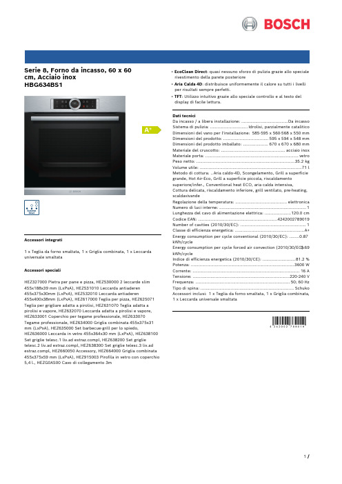
Serie 8, Forno da incasso, 60 x 60cm, Acciaio inoxHBG634BS1Accessori integrati1 x Teglia da forno smaltata, 1 x Griglia combinata, 1 x Leccarda universale smaltataAccessori specialiHEZ327000 Pietra per pane e pizza, HEZ530000 2 leccarde slim455x188x39 mm (LxPxA), HEZ531010 Leccarda antiaderen455x375x30mm (LxPxA), HEZ532010 Leccarda antiaderen455x400x38mm (LxPxA), HEZ617000 Teglia per pizza, HEZ625071 Teglia per grigliare adatta a pirolisi, HEZ631070 Teglia adatta a pirolisi e vapore, HEZ632070 Leccarda adatta a pirolisi e vapore, HEZ633001 Coperchio per tegame professionale, HEZ633070 Tegame professionale, HEZ634000 Griglia combinata 455x375x31 mm (LxPxA), HEZ635000 Set barbecue-grill per lo spiedo,HEZ636000 Leccarda in vetro 455x364x30 mm (LxPxA), HEZ638100 Set griglie telesc.1 liv.ad pl, HEZ638200 Set griglie telesc.2 liv.ad pl, HEZ638300 Set griglie telesc.3 liv.ad pl, HEZ660050 Accessory, HEZ664000 Griglia combinata 455x375x59 mm (LxPxA), HEZ915003 Pirofila in vetro con coperchio 5,4 l., HEZG0AS00 Cavo di collegamento 3m • EcoClean Direct: quasi nessuno sforzo di pulizia grazie allo speciale rivestimento della parete posteriore• Aria Calda 4D: distribuisce uniformemente il calore su tutti i livelli per risultati sempre perfetti.• TFT: Utilizzo intuitivo grazie allo speciale controllo e al testo del display di facile lettura.Dati tecniciDa incasso / a libera installazione: .....................................Da incasso Sistema di pulizia: ..............................Idrolisi, parzialmente catalitico Dimensioni del vano per l'installazione: 585-595 x 560-568 x 550 mm Dimensioni del prodotto: ....................................595 x 594 x 548 mm Dimensioni del prodotto imballato: ....................670 x 670 x 680 mm Materiale del cruscotto: ...................................................acciaio inox Materiale porta: ..........................................................................vetro Peso netto: ..............................................................................35.2 kg Volume utile: .................................................................................71 l Metodo di cottura: ..Aria caldo-4D, Scongelamento, Grill a superficie grande, Hot Air-Eco, Grill a superficie piccola, riscaldamento superiore/infer., Conventional heat ECO, aria calda intensiva,Cottura delicata, riscaldamento inferiore, grill ventilato, pre-heating, scaldavivandeRegolazione della temperatura: .........................................elettronica Numero di luci interne: (1)Lunghezza del cavo di alimentazione elettrica: .....................120.0 cm Codice EAN: (4242002789019)Number of cavities (2010/30/EC): (1)Classe di efficienza energetica: .......................................................A+ Energy consumption per cycle conventional (2010/30/EC): ........0.87 kWh/cycleEnergy consumption per cycle forced air convection (2010/30/EC):0.69 kWh/cycleIndice di efficienza energetica (2010/30/CE): ..........................81.2 % Potenza: ..................................................................................3600 W Corrente: .....................................................................................16 A Tensione: .............................................................................220-240 V Frequenza: ...........................................................................50; 60 Hz Tipo di spina: ..........................................................................Schuko Accessori inclusi: 1 x Teglia da forno smaltata, 1 x Griglia combinata, 1 x Leccarda universale smaltataSerie 8, Forno da incasso, 60 x 60cm, Acciaio inoxHBG634BS1Tipo di forno e modi di riscaldamento- Volume interno: 71 l- 13 modi di riscaldamento: Aria caldo-4D, Aria caldo Eco, Riscaldamento superiore/inferiore, Riscaldamentosuperiore/inferiore Eco, Grill ventilato, Grill a superficie grande, Grill a superficie piccola, Funzione pizza, Riscaldamento inferiore, Cottura delicata, Scongelamento, Preriscaldamento, Scaldavivande - Riscaldamento rapidoSupporto per accessori / Sistema d`estrazione:- Guide telescopiche accessorio opzionaleDesign- Illuminazione interna alogena, Illuminazione forno disinseribileComfort- 2,5“-TFT-color and text Display con funzione Direct-Touch- Orologio elettronico- Cerniera in basso, Porta cucine SoftClose, Porta del forno con Soft Open e Soft ClosePulizia- Pulizia Eco Clean Direct per parete posterioreAccessorio:- 1 x Leccarda universale smaltata, 1 x Griglia combinata, 1 x Teglia da forno smaltataAmbiente e Sicurezza- Sicurezza bambini- Interruttore di sicurezza per forno Spia di calore residuo Pulsante Start-/Stop Interruttore di contatto portaInformazioni tecniche- Dimensioni nicchia (AxLxP): 585 mm - 595 mm x 560 mm - 568 mm x 550 mm- Dimensioni apparecchi (AxLxP): 595 mm x 594 mm x 548 mm- Lungh. cavo alimentazione: 120 cm- Potenza max. assorb. (elettr.): 3.6 kWSerie 8, Forno da incasso, 60 x 60cm, Acciaio inox HBG634BS1。
Galaxy Pulsar Edge CP841A 迷你型大功率应用控制器说明书

- SSL
- SSH
Standard System Features
• Monitor and control of more than 40 connected devices - Maximum of 32 rectifiers - Maximum of 6 distribution control cards - Robust RS485 system bus
• Industry standard defaults - Customer specific configurations available
• Remote/ local software upgrade
• Basic, busy hour, and trend statistics
• Detailed event history
Key Features
Remote Access and Features
• Integrated 10/100Base-T Ethernet Network - TCP/IP - SNMP V3 for management - SMTP for email - Telnet for command line interface - DHCP for plug-n-play - FTP for rapid backup and upgrades - HTTP for standard web pages and browsers - Compatible with Galaxy Manager and other management packages - Shielded RJ-45 interface referenced to chassis ground
Saeco HD8856 05 浓缩咖啡机说明书

完美、热、干净。
这就是高端的奶泡体验Exprelia 可随时为您冲泡杯杯地道的香醇咖啡。
无论您喜欢什么味道,只需轻轻一按。
咖啡机的即时饮品选择界面以及双加热器,让您随意选择,随时喝到最爱的咖啡。
原汁原味的完美意式咖啡集成式储奶容器,打造完美奶泡双加热器,即刻获得鲜奶特制品完全采用陶瓷研磨器,咖啡不会烧焦根据您的口味制作饮料保留您喜爱的咖啡设置可调节研磨器,调出各种咖啡提升咖啡 Crema 层和浓度易于清洁和保养自动清洁与除垢让机器始终洁净如初全自动双清洁,打造洁净卫生的奶泡可分离式烹煮套件,清洁极为方便采用不锈钢表面前沿设计产品亮点不锈钢前沿设计的 Saeco 浓缩咖啡机采用经过打磨的不锈钢表面。
不锈钢可呈现优质外观,成为厨柜上的亮点。
其还具有更出色抗腐蚀性,确保持久性能。
完全采用陶瓷研磨器这款浓缩咖啡机配有全陶瓷研磨器。
Saeco 采用陶瓷研磨器,可获得均匀的研磨效果而不会使咖啡豆过热,制作出完美口味浓缩咖啡。
陶瓷还可以确保持久的性能和全静音操作。
8档可调节研磨器不同的咖啡粉要求不同大小的颗粒才能展现全部风味。
这款浓缩咖啡机的研磨颗粒为 8 档调节,从制作醇厚浓缩咖啡的最细研磨档到品味较淡咖啡的最粗研磨档。
保留您的咖啡设置得益于我们创新的可调节咖啡醇度、浓度和温度的记忆功能,您始终可以根据个人喜好,冲煮一杯属于自己的完美浓缩咖啡。
只需按一下按钮,便可用您喜爱的咖啡杯享用高品质咖啡饮品。
可分离式烹煮套件Saeco 发明的冲煮套件是确保浓缩咖啡机自动冲煮的核心部件。
可从正面或侧面轻松操作冲煮套件,具体取决于型号。
可将其轻松拆卸,放在水龙头下轻松冲洗,确保最佳清洁效果。
自动双清洁储奶容器这款 Saeco 浓缩咖啡机可对储奶容器进行全自动双清洁。
双清洁采用两个独立的蒸汽清洗周期,可在制作每种咖啡饮品后快速冲洗储奶容器,确保牛奶饮品始终新鲜美味。
享受洁净卫生的奶泡从未如此简单。
自动清洁与除垢Saeco 把这款浓缩咖啡机设计为在机器开机或关闭时,自动用水清洁咖啡回路,令每一杯咖啡都呈现出非凡、清新的口味。
CA系列专业power电raisar说明书

User's M anualPROFESSIONAL POWER AMPLIFIERCA1N CA1LCA SERIESCA2N CA2LCA3N CA3LCA4N CA4LS M-11021604-Z Lseries professional .Please carefully read and strictly follow the user's m anual w hen y ou u seCA amplifier. If you have any question, please contact the local dealer DEAR CUSTOMERS:CATALOGUEP1P1P2P10P11P11P12P12P13P15P15P15P161、2、3、4、5、6、7、8、9、10、11、12、13、AttentionsFunctions&features Parameters Installation Front panel Rear panel Power supplyInput/Output connectorsFunction setup and cable connectionOperationsIndicators on front panel Protection functionsTroubles and troubleshootings1、NOTESHigh voltage inside the equipment. Do not open the cover. Ask for the help from theprofessionals when need servicing.Please do not expose the equipment in the rain or moisture.Keep adequate ventilation, do not block the port.Be sure the voltage of this equipment complies with the local industrial voltage.Please put off the power plug if unused for a long time.Please connect rated load. Never working under the overload for a long time.Symbols:The equilateral triangle with lightning bolt warns the user of dangerous voltage levelslocalized within the cabinet.The equilateral triangle with exclamatory mark means the important operation on theuser's manual.2、FEATURESCA series is the amplifier with big power and excellent performance. It can meet different audio avenues.1> Big power,dynamic energy;2> Innovative heat sink structure and high quality heat sink fan assure reliable working fortime;a long3> "loading impedance temperature-power-running voltage" can be controlled alternately,Speed of Fan is automatic adjusted by temperature. When load is too low or temperature is too high, the equipment can adjust the power supply and lower impedance of power, which improves sound quality and protect the equipment better. The reliability will be improved remarkably;4> Low distortion;5> High slew speed, outstanding sound quality and high transparent;6> Low noise:S/N>108dB(A Weight);7> 20Hz~20KHz <+0/-0.25 dB;wide frequency band;8> Small dimension, 2U rack mounting.9> CA4L is specially designed for low loading imedance,andcan work for a long time under 2Ω.Stereo modeParallel mono mode Bridged mono mode<0.05%(10%Rated power )<0.1%(60Hz/7kHz,10%Rated power )Short Circuit, Maladjustment of DC, Overload, Overheat ,Etc Four fans ,stepless shifting,Cooling airflow from front to back483×452×88mm 30kg≤90%Working temperature: -10℃~40℃ Storing temperature: -25℃~80℃1V>100V/sμUnbalanced input 10k ,Balanced input 20k ΩΩThree pin XLR/6.35mmSpeakon binding post,NL4 speakon Parallel/Stereo/Bridge, LF cutting,Grounding,Limit Yellow-Bridge,Red-Overload,Green-Signal20Hz~20kHz(+0/-0.25dB)<±15°>800(8/100Hz)Ω>75dB>108dB(A-Weight)39±0.5dB <0.25dB THDIntermodulation distortionFrequency response Phase difference Damping factors Segregation S/N Total gain Input sensitivity Slew speed Input impedance Input connectors Output connectors CoolingControls on front panel Controls on rear panel Indicator on front panel Amplifier protection Dimensions Net weight Power supply Environment humidityEnvironment TemperatureDifference of Channel gain Switch of AC,Gain controlling knob for channel A and B 8Ω8Ω16Ω1000W 1000W 2000W 1600W 1600W 3200W4Ω4Ω8ΩRated PowerAC 220V/50~60Hz,1500VA<0.05%(10%Rated power )<0.1%(60Hz/7kHz,10%Rated power )Short Circuit, Maladjustment of DC, Overload, Overheat ,Etc Four fans ,stepless shifting,Cooling airflow from front to back483×452×88mm 30kg≤90%Working temperature: -10℃~40℃ Storing temperature: -25℃~80℃1V>70V/sμUnbalanced input 10k ,Balanced input 20k ΩΩThree pin XLR/6.35mmSpeakon binding post,NL4 speakon Parallel/Stereo/Bridge, LF cutting,Grounding,Limit Yellow-Bridge,Red-Overload,Green-Signal20Hz~20kHz(+0/-0.25dB)<±15°>800(8/100Hz)Ω>75dB>108dB(A-Weight)35.7±0.5dB <0.25dB THDIntermodulation distortionFrequency response Phase difference Damping factors Segregation S/N Total gain Input sensitivity Slew speed Input impedance Input connectors Output connectors CoolingControls on front panel Controls on rear panel Indicator on front panel Amplifier protection Dimensions Net weight Power supply Environment humidityEnvironment TemperatureDifference of Channel gain Switch of AC,Gain controlling knob for channel A and B AC 220V/50~60Hz,1500VA Stereo modeParallel mono mode Bridged mono mode4Ω4Ω8Ω950W 950W 1900W 1500W 1500W 3000W2Ω2Ω4ΩRated Power<0.05%(10%Rated power )<0.1%(60Hz/7kHz,10%Rated power )Short Circuit, Maladjustment of DC, Overload, Overheat ,Etc Four fans ,stepless shifting,Cooling airflow from front to back483×375×88mm 18kg≤90%Working temperature: -10℃~40℃ Storing temperature: -25℃~80℃1V>80V/μsUnbalanced input 10k ,Balanced input 20k ΩΩThree pin XLR/6.35mmSpeakon binding post,NL4 speakon Parallel/Stereo/Bridge, LF cutting,Grounding,Limit Yellow-Bridge,Red-Overload,Green-Signal20Hz~20kHz(+0/-0.25dB)<±15°>800(8/100Hz)Ω>75dB>108dB(A-Weight)37.3±0.5dB <0.25dB THDIntermodulation distortionFrequency response Phase difference Damping factors Segregation S/N Total gain Input sensitivity Slew speed Input impedance Input connectors Output connectors CoolingControls on front panel Controls on rear panel Indicator on front panel Amplifier protection Dimensions Net weight Power supply Environment humidityEnvironment TemperatureDifference of Channel gain Switch of AC,Gain controlling knob for channel A and B AC 220V/50~60Hz,1000VA Stereo modeParallel mono mode Bridged mono mode8Ω8Ω16Ω660W 660W 1330W 1000W 1000W 2000W4Ω4Ω8ΩRated Power<0.05%(10%Rated power )<0.1%(60Hz/7kHz,10%Rated power )Short Circuit, Maladjustment of DC, Overload, Overheat ,Etc Four fans ,stepless shifting,Cooling airflow from front to back483×375×88mm 15kg≤90%Working temperature: -10℃~40℃ Storing temperature: -25℃~80℃1V>80V/sμUnbalanced input 10k ,Balanced input 20k ΩΩThree pin XLR/6.35mmSpeakon binding post,NL4 speakon Parallel/Stereo/Bridge, LF cutting,Grounding,Limit Yellow-Bridge,Red-Overload,Green-Signal20Hz~20kHz(+0/-0.25dB)<±15°>800(8/100Hz)Ω>75dB>108dB(A-Weight)34.2±0.5dB <0.25dB THDIntermodulation distortionFrequency response Phase difference Damping factors Segregation S/N Total gain Input sensitivity Slew speed Input impedance Input connectors Output connectors CoolingControls on front panel Controls on rear panel Indicator on front panel Amplifier protection Dimensions Net weight Power supply Environment humidityEnvironment TemperatureDifference of Channel gain Switch of AC,Gain controlling knob for channel A and B AC 220V/50~60Hz,900VAStereo modeParallel mono mode Bridged mono mode4Ω4Ω8Ω660W 660W 1300W 1000W 1000W 2000W2Ω2Ω4ΩRated Power<0.05%(10%Rated power )<0.1%(60Hz/7kHz,10%Rated power )Short Circuit, Maladjustment of DC, Overload, Overheat ,Etc Four fans ,stepless shifting,Cooling airflow from front to back483×375×88mm 15kg≤90%Working temperature: -10℃~40℃ Storing temperature: -25℃~80℃1V>60V/sμUnbalanced input 10k Ω,Balanced input 20k ΩThree pin XLR/6.35mmSpeakon binding post,NL4 speakon Parallel/Stereo/Bridge, LF cutting,Grounding,Limit Yellow-Bridge,Red-Overload,Green-Signal20Hz~20kHz(+0/-0.25dB)<±15°>800(8/100Hz)Ω>75dB>108dB(A-Weight)34±0.5dB <0.25dB THDIntermodulation distortionFrequency response Phase difference Damping factors Segregation S/N Total gain Input sensitivity Slew speed Input impedance Input connectors Output connectors CoolingControls on front panel Controls on rear panel Indicator on front panel Amplifier protection Dimensions Net weight Power supply Environment humidityEnvironment TemperatureDifference of Channel gain Switch of AC,Gain controlling knob for channel A and B AC 220V/50~60Hz,500VAStereo modeParallel mono mode Bridged mono mode8Ω8Ω16Ω330W 330W 660W 500W 500W 1000W4Ω4Ω8ΩRated Power<0.05%(10%Rated power )<0.1%(60Hz/7KHz,10%Rated power )Short Circuit, Maladjustment of DC, Overload, Overheat ,Etc Four fans ,stepless shifting,Cooling airflow from front to back483×375×88mm 12.5kg≤90%Working temperature: -10℃~40℃ Storing temperature: -25℃~80℃1V>80V/sμUnbalanced input 10k Ω,Balanced input 20k ΩThree pin XLR/6.35mmSpeakon binding post,NL4 speakon Parallel/Stereo/Bridge, LF cutting,Grounding,Limit Yellow-Bridge,Red-Overload,Green-Signal20Hz~20KHz(+0/-0.25dB)<±15°>800(8/100Hz)Ω>75dB>108dB(A-Weight)31.2±0.5dB <0.25dB THDIntermodulation distortionFrequency response Phase difference Damping factors Segregation S/N Total gain Input sensitivity Slew speed Input impedance Input connectors Output connectors CoolingControls on front panel Controls on rear panel Indicator on front panel Amplifier protection Dimensions Net weight Power supply Environment humidityEnvironment TemperatureDifference of Channel gain Switch of AC,Gain controlling knob for channel A and B AC 220V/50~60Hz,400VAStereo modeParallel mono mode Bridged mono mode4Ω4Ω8Ω330W 330W 660W 500W 500W 1000W2Ω2Ω4ΩRated Power<0.05%(10%Rated power )<0.1%(60Hz/7kHz,10%Rated power )Short Circuit, Maladjustment of DC, Overload, Overheat ,Etc Four fans ,stepless shifting,Cooling airflow from front to back483×310×88mm 11kg≤90%Working temperature: -10℃~40℃ Storing temperature: -25℃~80℃1V>80V/sμUnbalanced input 10k Ω,Balanced input 20k ΩThree pin XLR/6.35mmSpeakon binding post,NL4 speakon Parallel/Stereo/Bridge, LF cutting,Grounding,Limit Yellow-Bridge,Red-Overload,Green-Signal20Hz~20kHz(+0/-0.25dB)<±15°>800(8/100Hz)Ω>75dB>108dB(A-Weight)32±0.5dB <0.25dB THDIntermodulation distortionFrequency response Phase difference Damping factors Segregation S/N Total gain Input sensitivity Slew speed Input impedance Input connectors Output connectors CoolingControls on front panel Controls on rear panel Indicator on front panel Amplifier protection Dimensions Net weight Power supply Environment humidityEnvironment TemperatureDifference of Channel gain Switch of AC,Gain controlling knob for channel A and B AC 220V/50~60Hz,250VAStereo modeParallel mono mode Bridged mono mode8Ω8Ω16Ω200W 200W 400W 300W 300W 600W4Ω4Ω8ΩRated Power3、PARAMETERS-CA1L<0.05%(10%Rated power )<0.1%(60Hz/7kHz,10%Rated power )Short Circuit, Maladjustment of DC, Overload, Overheat ,Etc Four fans ,stepless shifting,Cooling airflow from front to back 483×310×88mm 11kg ≤90%Working temperature: -10℃~40℃ Storing temperature: -25℃~80℃1V >80V/s μUnbalanced input 10k ,Balanced input 20k ΩΩThree pin XLR/6.35mm Speakon binding post,NL4 speakon Parallel/Stereo/Bridge, LF cutting,Grounding,Limit Yellow-Bridge,Red-Overload,Green-Signal 20Hz~20kHz(+0/-0.25dB)<±15°>800(8/100Hz)Ω>75dB >108dB(A-Weight)29±0.5dB <0.25dB THDIntermodulationdistortionFrequency responsePhase differenceDamping factorsSegregationS/NTotal gainInput sensitivitySlew speedInput impedanceInput connectorsOutput connectorsCoolingControls on front panelControls on rear panelIndicator on front panelAmplifier protectionDimensionsNet weightPower supplyEnvironment humidity EnvironmentTemperatureDifference ofChannel gainSwitch of AC,Gain controlling knob for channel A and B AC 220V/50~60Hz,250VA Stereo modeParallel mono modeBridged mono mode4Ω4Ω8Ω200W 200W 400W 300W 300W 600W 2Ω2Ω4ΩRated Power76.2m m 446mm441mm435.7mm430.5mm 482.4mm 465.0m m气流方向气流方向446m m 425m m 433.0m m87.9m m气流方向气流方向CA4N/CA4L76.2m m 376mm371mm365.7mm360.5mm 482.4m m465.0mm 气流方向气流方向376m m 355m m 433.0m m 87.9m m气流方向气流方向CA2N/CA2L/CA3N/CA3L76.2m m 310mm302.5mm298mm292.5mm 482.4mm 465.0m m 气流方向气流方向310m m 287m m 433.0m m 87.9m m气流方向气流方向CA1N/CA1L4、INSTALLATIONSCA SERIES PRO DESIGN PROFESSIONAL AMPLIFIERS B R I D G EP E A KS I G N A L0-2-4-6-8-10-12-14-16-18-20-240-2-4-6-8-10-12-14-16-18-20-24CHBCHA POWER ONCA4N123456789CHABRIDGE IN CHB PIN1:SIGNAL GND PIN2:SIGNAL +PIN3: SIGNAL -BRIDGE PARALLEL STEREO MODE LF FILTER GROUND CLIPLIMITER ON OFF 50HZ 25HZ ON OFF CHB OUTPUT CHA OUTPUT POWER CABLEFUSE BETA THREEPROFESSIONAL AMPLIFIERS INPUTAC 220V 50~60Hz -B +-A +-+5HZ CAUTIONRISK OF ELECTRIC SHOCKDO NOT OPENB R I D G E !1234567891011121314RMS:STERO:8Ω 1000W ×2BRIDGE: 16Ω 2000W OUTPUT ASSIGNMENT:BRIDGE MONO OUTPUT:CHA : PIN1+ : SIGNAL GND CHA: 4Ω 1600W ×2 8Ω 3200WPIN 1+ :PIN 1 - :PIN 2+ :PIN 2 - : CHA SIGNALCHA GND CHB SIGNAL CHB GND CHB:PIN 1+ :PIN 1 - :PIN 2+ :PIN 2 - :CHB SIGNAL CHB GND PIN2+ : 5、FRONT PANELFOR EXAMPLE:CA4N1、 air input port2、 signal indicator of channel A3、 overload indicator of channel A4、 bridge indicator of channel5、 overload indicator of channel B6、 signal indicator of channel B7、 power switch8、 gain adjustment pots of channel A9、 gain adjustment pots of channel B1、signal input of channel A(XLR JACK)2、signal input of channel A(1/4″mic jack)3、switch of working modes4、limiters5、signal output of channel B(binding post)6、signal output of channel A(binding post)7、fuse 8、signal input of channel B(XLR plug)9、signal input of channel B(1/4″mic jack)10、filter switch 11、 grounding switch 12、signal output of channel A(NL4 JACK)13、signal output of channel B(NL4 JACK)14、cable6、REAR PANELFOR EXAMPLE:CA4N7、POWER SUPPLY8、INPUT/OUTPUT CONNECTORSPlease assure the local voltage comply with the voltage indicated on rear panel before connecting power supply ();Please assure the cable and jack of power supply not damaged before connecting power supply; Put off the plug after power off;AC 220V/50Hz~60Hz The XLR jack and 1/4″microphone jack in same channel are paralleled;Input the signal from either connectors and output the signal for connecting next amplifier; If the amplifiers connected are too many, the sound quality may be affected;Please do not input the signal from two connectors in same channel at the same time.Input connectorsOutput connectorsThe binding post and NL4 jack in same channel of "CA series "amplifier are paralleled;Do not connect loads to the two connectors at the same time;The red end of binding post is connected with anode of speaker, the black end connected with cathode of speaker;Only the load suited with the power and impedance of amplifier can be connected with the output connectors of amplifier.1> :Limiter setup 2> LF cutting setup:9、L F F I L T E R 50HZ 25HZ 5HZ+1-2-3-4-5-60dB -120 30 40 50 60 80 100 200 300 400 500 HzAs the below drawing, when switch is OFF, the limit is off,the limit c ircuit i s o ut o f w ork, if input signal is too strong,output can cause clip distortion and also raise overload onloudspeakerAs the below drawing, when the switch is ON, the limit ison, if the input signal is too strong, the limit circuit cancontrol the gain and reduce the distortion, also control theaverage output power, but it does not affect peak power,protect the loudspeaker and assure the dynamic of music.Note: Please set to "ON" position when using.When LF cutting is at 50Hz,it equals discrete a 50Hzhigh pass filter on input, the signal lower than 50Hz willbe accordingly attenuated, then can reduce thenoneffective swing and lower the distortion.Like the right drawing: When LF cutting is at 25Hz, it equals discrete a 25Hz high pass filter on input circuit, it just attenuate the signal lower than 25Hz.Like the right drawing:FUNCTION SETUP AND CABLE CONNECTINGL F F I L T E R 50HZ 25HZ 5HZ +1-2-3-4-5-60dB-120 30 40 50 60 80 100 200 300 400 500 HzC L I P L I M I T E R OFF ON C L I P L I M I T E R OFF ONUnder the bridge mode, The output voltage is so high enough to make a electronic shock. Please power off the unit before operate it under bridge mode.please select CA4L10、11、12、Please follow the steps during using the equipment1> Starta、Setup the f unction a nd c onnection a ccording t o t he a bove f unction s etup a ndconnecting;b、Check if the output cable is short circuit and the load is too low;c、Check if the local voltage complies with the user's manual;d、Be sure the switch of power supply at "0" and the volume is the lowest;e、Connect the power supply, turn on the equipment of sound source, pre and effectequipment and assure these equipments work in order;f、 Turn on the switch of power supply(put it at"1"position);g、Adjust the knob of volume clockwise to right position.2> Offa、Adjust the knob of volume unti-clockwise to the lowest;b、Turn off the switch of power supply on the front panel(put it at "0"position);c、Turn off the pre and effect equipments, sound source equipments;1>If signal indicator flashes, it means if there is signal output in two channels2>If peak indicator flashes, it means that the input voltage is too high. You should turndown the volume;3>If the peak indicator always lights,it means faults.The reason is like this: loading is toolow,short on loading,temperature is too high.You should check it after power off. Turn on again if no abnormity;4>If bridge indicator lights, it means the amplifier is under the bridged mode.;Perfect protection function can prevent the damage for amplifier and speaker caused by short circuit and output DC and overheat.1>Short circuit protection: when the load at the output end is short circuit, the equipmentcan cut off the signal and protect the equipment;2>Output DC protection: when the equipment has faults and there is DC in output signal,the equipment can cut off output automatically and avoid damage for speaker caused by DC;3>Overheat protection: If the temperature of heat sink is over the allowed temperature,the sensor will cut off the output ,avoid damage caused by high temperature a nd p rotect the a mplifier.OPERATIONSINDICATORS ON FRONT PANELPROTECTION FUNCTION13、Trouble SNTroublele shootings Check if the power plug and jack are connected well.Check if the music signal cable is connected well.If the power jack correspondswith .AC 220V/50~60Hz Check if the power of music source is turned on and the volume is turned on.Check if the fuse on rear panel is broken.If the volume pots is turned on.If the music source output is too big.If the CLIP LIMITER is at the "ON"position.Check if there is any short circuit in outputconnectons and if the load is correct. The restart.If the LF FILTER on rear panel is at the LF 50Hz or at LF 25Hz, setup the switch at appropriate place.Check if the switch of MODE on rear panel isat the PARALLEL,please put it at PARALLEL if it not at the position.Check the input signal can comply with voltage, please enhance the input signal if not sufficient.11223312311111Check if input SIGNAL voltage is suited, please enhance the input SIGNAL if not sufficient.2Check the local voltage is same as the voltage of the equipment.Check if the setup and connection are accordant with the user manual.No voice, Power indicator lights off No voice, Power indicator Lights, Signal indicator Light off CLIP indicator last slighting on, Voice is abnormal The bass is not sufficient No voice on one channel under paralleled mono mode Output of bridge is too low Burning the fuse when start Others TROUBLES AND TROUBLE SHOOTINGS。
ES8A-恒线速车床说明书
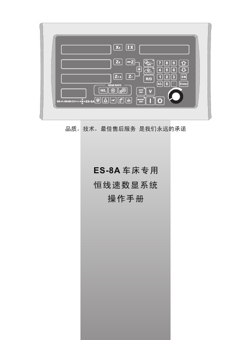
基本功能按 键 板信息显示屏TOOL. ; r ; R ; L 与 V )。
TOOL. ?? (表示刀具偏移坐标)r ???(主轴输出旋转速度,单位RPM)R ???(主轴测量旋转速度,单位RPM)L ???(当前直线加工速度,单位M/min)V ???(当前测量直线加工速度,单位M/min)?显示当前齿轮设置/直径显示切换键例如:H1-2 :H-高速1-齿轮 1设置为比率1 2-齿轮 2设置为比率2**1自动 rpm**2手动rpm**3主轴打开**4主轴关闭如果 ES-8A 在自动 rpm 模式下工作,至变频器的主轴输出电压(0-10V )会自动设定,主轴转速与直线加工速度L (直线速度预设值)相匹配。
如果 ES-8A 在手动 rpm 模式下工作,至变频器的主轴输出电压可通过主轴转速旋钮调节。
如果 ES-8A 在此模式下工作,系统会向主轴变频器发出一个使能信号开启主轴。
基本功能 - 清 零功能: 操作者在任何位置将显示坐标归零。
例子: 在现时的位置将 Z 轴显示清零。
公/英制显示功 能: 将显示的位置尺寸,以公制 (mm) 或英制 (inch) 作单位。
例 子: 现时显示的位置尺寸为 英制 (inch),要转到以公制 (mm) 作显示。
例子: 现时显示的位置尺寸为 公制 (mm),要转到以英制 (inch) 作显示.尺 寸 预 设功能: 将现时机床的位置,设置为任何数值。
例子: 将现时 X轴的位置设定为 45.8mm。
基本功能- ABS/INC 坐标显示转换功能:操作者可将工件基准零点记忆在 ABS 坐标,然后转到 INC 坐标内进行操作加工。
操作者可以自由地在 INC 坐标下清零或任何相对位置机器加工而在任何轴内预设尺寸大小, 工件数据(工件零位置)始终被保存在 ABS 坐标里,不会受到影响。
不会丢失工件数据,操作者可以在 ABS(绝对)和 INC(相对)坐标之间转换。
数显表提供两组基本的坐标显示,分别是 ABS(绝对)及 In(相对)坐标。
PreSonus Eris E5E8中文手册
为 Eris 专家。除高级用户提示之外,还可以找到一些教 程涵盖了监听器安防以及设置输入电平、EQ 以及声学空
间控件。
中文
1
1.2 Eris E5/E8 功能摘要
1.2 Eris E5/E8 功能摘要
• 3 输入:2 个平衡(XLR 以及 ¼”TRS)和 1 个非 平衡(RCA)插口
小心:为降低触电风险,请勿让本装置遭 雨淋和受潮。本装置不得被液体滴洒或泼 溅,而且内盛有液体的物件(如花瓶)也不得置 于本装置上。
小心:这些维修说明仅供专业维修人员使 用。为降低触电风险,请勿执行操作手册 中未介绍的任何维修工作。必须由专业维修人员 进行修理。
1. 阅读这些说明。 2. 保存这些说明。 3. 留意所有警告。 4. 遵循所有说明。 5. 请勿在靠近水源的地方使用本装置。 6. 仅用干布清洁。 7. 请勿堵塞任何通风口。请按照制造商的说明
13. 在雷暴期间或长时间不用时,请拔掉本装置
的电源插头。
14. 本装置如遇任何形式的损坏,均需要维修,
例如:电 源线 或插头 损坏;液体溅 入 或物 体 落入 本 装 置;或 者 本 装 置 受 到 雨 淋 或 受 潮、 不 能 正 常 运 行 或 摔 落 到 地 面。美 国 境 内 的
所 有 PreSonus 产 品 均 应 在 路 易斯 安 那州巴 吞 鲁 日(Baton Rouge)市 的 PreSonus 工 厂 进
则输入增益设置为 U 或者稍低都应该没有问题。
一旦监听器输入增益控件设定,就不要变动了;不要将其作为 系统音量调节控件。请使用音频设备的输出电平控件调节音量。
3.3 均衡器设置建议
Eris E5/E8 在声学微调方面提供 3 个 EQ 控件:高、
瑞萨电子 MCU型号 速查手册

2010.09瑞萨电子M C U 型号速查手册QzROM 低功耗720、740工具R8C族及工具M16C R32C M16C族工具SuperH族及工具安全MCU 芯片封装说明78K V85078K、V850工具QzROM 13720族、740族开发工具介绍4低功耗6R8C族及其开发工具介绍23M16C族29M16C族R32C34M16C族开发工具介绍36SuperH RISC engine族及其开发工具介绍45安全MCU 78芯片封装说明5078K 65V8507578K、V850微控制器开发工具介绍瑞萨电子MCU 型号速查手册QzROM1QzROM 低功耗720、740工具78K、V850工具R8C族及工具SuperH族及工具M16C族工具安全MCU 78K V850芯片封装说明M16C R32C2QzROMM16C R32CM16C族工具安全MCU78K V850芯片封装说明720、740工具78K、V850工具QzROM低功耗R8C族及工具SuperH族及工具3720族、740族开发工具QzROM 低功耗720、740工具78K、V850工具R8C族及工具SuperH族及工具M16C族工具安全MCU 78K V850芯片封装说明M16C R32CM16C R32CM16C族工具安全MCU78K V850芯片封装说明720、740工具78K、V850工具QzROM低功耗R8C族及工具SuperH族及工具5低功耗QzROM 低功耗720、740工具78K、V850工具R8C族及工具SuperH族及工具M16C族工具安全MCU 78K V850芯片封装说明M16C R32C6R8C族1x系列R 5F 21254S D X X X S P U 010*********瑞萨新MCU代码器件区分ex)F:闪存瑞萨R8C族代码瑞萨R8C群代码ex)R8C/1B, R8C/25存储器变化(仅R8C系列)0:2KB 1:4KB 2:8KB 3:12KB 4:16KB5:24KB 6:32KB 7:48KB 8:64KBA:96KB C:128KB(-):标准版本S :低电压版本A :R8C/3x的新增功能代码2ex) J -40~85℃ 汽车K -40~125℃ 汽车D -40~85℃ 工业N或无标记 -20~85℃ 消费类电子ROM型号(仅用于出厂编程的MCU)FP:LQFP, SP:LSSOP, NP:QFNFA:LQFP, DD:SDIP, LG:FLGAU0:无铅产品,盘装或管装出货W4:无铅产品,卷带出货无标记:含铅产品,盘装或管装出货T4:含铅产品,卷带出货ES:工程样品12345678910R8C族MCU命名规则QzROM 低功耗720、740工具78K、V850工具R8C族及工具SuperH族及工具M16C族工具安全MCU 78K V850芯片封装说明M16C R32C7R8C族1x系列QzROM 低功耗720、740工具78K、V850工具R8C族及工具SuperH族及工具M16C族工具安全MCU 78K V850芯片封装说明M16C R32C8R8C族1x系列注:① R8C/1x芯片的ROM类型均为Flash。
萨利亚汽车产品信息说明书

More information at /autoinfo Determine the best mounting location for the LED light assembly(ies), ensuring it does not interfere or block any existing vehicle systems. Mount LED assembly(ies).Attach the female spade connector wires (8) from the wiring harness to the exposed wires (8) on the mounted LED assemblies using the supplied male spade connector. There are 4 groupings of red and black wires connected to the wiring harness. From each grouping attach the black wire from the wiring harness to the black wire on the LED assembly. For each grouping also attach the red wire from the wiring harness to the red wire on the LED assembly. Be sure to secure loose wiring with zip ties and avoid mounting wiring near pinch points, sharp surfaces, and moving parts.Connect the positive (2) and negative (2) wires of the wiring harness using the crimped-on ring terminals. Connect the RED (+) wires to the positive battery terminal or switched +12V power source from the vehicle. Connect the BLACK (-) wires to either the negative terminal on the battery or appropriate vehicle ground (-) source.Turn on the LED assembly(ies) using the power switch on the wiring harness. Verify the LED assembly(ies) turns on and off properly with the switch. Verify the LEDs on the switch change from ON to OFF when pressing the switch button.Determine mounting location of the wiring harness relay. There is a plastic mounting tab attached to the wiring harness relay. Secure the relay closest to the vehicle battery using an existing vehicle mounting bolt or stud, or with a self-tapping screw. Be sure to mount the relay with the relay connector facing down, to prevent water from entering and damaging the relay.Safely unclip the white wiring harness connector attached to the wiring harness switch. Locate ideal mounting position for the switch. Remove adhesive backing from the switch and mount the switch. Run remaining wire attached to the switch along a preferred path of the vehicle and reattached the white wiring harness connector.1456234 OUTPUT HARNESSINSTALLATION GUIDECarefully read and understand the following instructions before proceeding.G1*******C10604538。
萨牌仪表说明书.

1 特性1.1 特点1.萨牌MDI多功能数字仪表是一个显示器,它适用于所有装有ZAPI高频电控器的各种形式的电动车辆。
2.萨牌MDI多功能数字仪表的信号取自斩波器,而不是电瓶,这样不同电压等级的车辆也可用同一仪表。
3.电瓶的放电状态由微处理器进行一定的换算模拟获得。
该换算考虑了制动及起动等大电流工况对电瓶的影响。
4.用萨牌MDI数字式手持单元,可以选择100种不同放电曲线。
5.萨牌MDI多功能数字仪表是一个以微处理器为基础的系统。
对电瓶放电状态测量是高精度的,具有很高的可靠性和灵敏度。
同时萨牌MDI多功能数字仪表还可以显示工作小时。
6.萨牌MDI多功能数字仪表有三个内部功能。
●显示放电状态。
●工作小时。
●显示控制系统故障。
7.萨牌MDI多功能数字仪表不直接连到电瓶,她仅与斩波器相连。
与传统显示仪表相比,萨牌MDI多功能数字仪表无需复杂接线,也节省了安装时间。
1.2 显示功能说明1.2.a 发光二极管显示功能萨牌MDI多功能数字仪表用发光二极管显示电瓶放电状态。
萨牌MDI多功能数字仪表有五个发光二极管,一红四绿,表示电瓶的放电状态。
充足电时,四个绿色发光二极管全亮。
随着电瓶不断放电,四个绿灯随电瓶剩余电量的减少逐步并按一定顺序熄灭,直至电瓶放完电,红灯开始闪烁,表示电瓶已开始过放电,斩波器进入低电压保护状态。
1.2.b 液晶显示功能小时计:在萨牌MDI多功能数字仪表中部装有液晶显示器,它可以用来显示1.工作小时2.系统故障,萨牌MDI多功能数字仪表显示故障状态时是以相应的代码表示,故障发生时,红色发光二极管将开始闪烁,以引起注意。
3.软件版本:电锁刚闭合时,萨牌MDI多功能数字仪表显示EPROM中的软件版本,即EP××,同时出现扳手图案。
4.其它信息,萨牌MDI多功能数字仪表上有三种图案,分别告知司机下列信息:乌龟图案:表示车辆处在“软”方式工作状态,在这种状态下,最大速度和加速度都被减小了。
瑞萨 910x 系列 A-GPS 应用笔记说明书

]LE910Cx/ME910C1/ML865C1/NE910C1A-GPS Application Note80529NT11738A Rev. 2 – 2019-11-221 7SPECIFICATIONS ARE SUBJECT TO CHANGE WITHOUT NOTICENOTICEWhile reasonable efforts have been made to assure the accuracy of this document, Telit assumes no liability resulting from any inaccuracies or omissions in this document, or from use of the information obtained herein. The information in this document has been carefully checked and is believed to be reliable. However, no responsibility is assumed for inaccuracies or omissions. Telit reserves the right to make changes to any products described herein and reserves the right to revise this document and to make changes from time to time in content hereof with no obligation to notify any person of revisions or changes. Telit does not assume any liability arising out of the application or use of any product, software, or circuit described herein; neither does it convey license under its patent rights or the rights of others.It is possible that this publication may contain references to, or information about Telit products (machines and programs), programming, or services that are not announced in your country. Such references or information must not be construed to mean that Telit intends to announce such Telit products, programming, or services in your country. COPYRIGHTSThis instruction manual and the Telit products described in this instruction manual may be, include or describe copyrighted Telit material, such as computer programs stored in semiconductor memories or other media. Laws in the Italy and other countries preserve for Telit and its licensors certain exclusive rights for copyrighted material, including the exclusive right to copy, reproduce in any form, distribute and make derivative works of the copyrighted material. Accordingly, any copyrighted material of Telit and its licensors contained herein or in the Telit products described in this instruction manual may not be copied, reproduced, distributed, merged or modified in any manner without the express written permission of Telit. Furthermore, the purchase of Telit products shall not be deemed to grant either directly or by implication, estoppel, or otherwise, any license under the copyrights, patents or patent applications of Telit, as arises by operation of law in the sale of a product.COMPUTER SOFTWARE COPYRIGHTSThe Telit and 3rd Party supplied Software (SW) products described in this instruction manual may include copyrighted Telit and other 3rd Party supplied computer programs stored in semiconductor memories or other media. Laws in the Italy and other countries preserve for Telit and other 3rd Party supplied SW certain exclusive rights for copyrighted computer programs, including the exclusive right to copy or reproduce in any form the copyrighted computer program. Accordingly, any copyrighted Telit or other 3rd Party supplied SW computer programs contained in the Telit products described in this instruction manual may not be copied (reverse engineered) or reproduced in any manner without the express written permission of Telit or the 3rd Party SW supplier. Furthermore, the purchase of Telit products shall not be deemed to grant either directly or by implication, estoppel, or otherwise, any license under the copyrights, patents or patent applications of Telit or other 3rd Party supplied SW, except for the normal non-exclusive, royalty free license to use that arises by operation of law in the sale of a product.USAGE AND DISCLOSURE RESTRICTIONSI. License AgreementsThe software described in this document is the property of Telit and its licensors. It is furnished by express license agreement only and may be used only in accordance with the terms of such an agreement.II. Copyrighted MaterialsSoftware and documentation are copyrighted materials. Making unauthorized copies is prohibited by law. No part of the software or documentation may be reproduced, transmitted, transcribed, stored in a retrieval system, or translated into any language or computer language, in any form or by any means, without prior written permission of Telit III. High Risk MaterialsComponents, units, or third-party products used in the product described herein are NOT fault-tolerant and are NOT designed, manufactured, or intended for use as on-line control equipment in the following hazardous environments requiring fail-safe controls: the operation of Nuclear Facilities, Aircraft Navigation or Aircraft Communication Systems, Air Traffic Control, Life Support, or Weapons Systems (High Risk Activities"). Telit and its supplier(s) specifically disclaim any expressed or implied warranty of fitness for such High Risk Activities.IV. TrademarksTELIT and the Stylized T Logo are registered in Trademark Office. All other product or service names are the property of their respective owners.V. Third Party RightsThe software may include Third Party Right software. In this case you agree to comply with all terms and conditions imposed on you in respect of such separate software. In addition to Third Party Terms, the disclaimer of warranty and limitation of liability provisions in this License shall apply to the Third Party Right software.TELIT HEREBY DISCLAIMS ANY AND ALL WARRANTIES EXPRESS OR IMPLIED FROM ANY THIRD PARTIES REGARDING ANY SEPARATE FILES, ANY THIRD PARTY MATERIALS INCLUDED IN THE SOFTWARE, ANY THIRD PARTY MATERIALS FROM WHICH THE SOFTWARE IS DERIVED (COLLECTIVELY “OTHER CODE”), AND THE USE OF ANY OR ALL THE OTHER CODE IN CONNECTION WITH THE SOFTWARE, INCLUDING (WITHOUT LIMITATION) ANY WARRANTIES OF SATISFACTORY QUALITY OR FITNESS FOR A PARTICULAR PURPOSE.NO THIRD PARTY LICENSORS OF OTHER CODE SHALL HAVE ANY LIABILITY FOR ANY DIRECT, INDIRECT, INCIDENTAL, SPECIAL, EXEMPLARY, OR CONSEQUENTIAL DAMAGES (INCLUDING WITHOUT LIMITATION LOST PROFITS), HOWEVER CAUSED AND WHETHER MADE UNDER CONTRACT, TORT OR OTHER LEGAL THEORY, ARISING IN ANY WAY OUT OF THE USE OR DISTRIBUTION OF THE OTHER CODE OR THE EXERCISE OF ANY RIGHTS GRANTED UNDER EITHER OR BOTH THIS LICENSE AND THE LEGAL TERMS APPLICABLE TO ANY SEPARATE FILES, EVEN IF ADVISED OF THE POSSIBILITY OF SUCH DAMAGES.APPLICABILITY TABLE PRODUCTSME910C1 SERIESNE910C1 SERIESML865C1 SERIESLE910C1/C4 SERIESCONTENTSNOTICE 2COPYRIGHTS (2)COMPUTER SOFTWARE COPYRIGHTS (2)USAGE AND DISCLOSURE RESTRICTIONS (3)I.License Agreements (3)II.Copyrighted Materials (3)III.High Risk Materials (3)IV.Trademarks (3)V.Third Party Rights (3)APPLICABILITY TABLE (4)CONTENTS (5)1.INTRODUCTION (6)2.BACKGROUND INFORMATION (9)A Brief GPS Introduction (9)GNSS – Global Navigation Satellite System (10)Time to First Fix (TTFF) (10)3.GNSS SOLUTION (11)Standalone GNSS (11)A-GPS – Secure User Plane Location (SUPL) – Ms-Based (12)4.GLOSSARY AND ACRONYMS (17)5.DOCUMENT HISTORY (18)1. INTRODUCTIONThe present document provides the reader with a guideline concerning the use of the Assisted GPS (A-GPS) provided by the Telit’s Modules of the ME910 family.1.1. ScopeThe Application Note covers the Secure User Plane Location (SUPL) standard created by the OMA standardization body.1.2. AudienceThis document is intended for those users that need to develop applications dealing with LoCation Service (LCS).1.3. Contact Information, SupportFor general contact, technical support services, technical questions and report documentation errors contact Telit Technical Support at:•*****************•*********************•*****************Alternatively, use:/supportFor detailed information about where you can buy the Telit modules or for recommendations on accessories and components visit:Our aim is to make this guide as helpful as possible. Keep us informed of your comments and suggestions for improvements.Telit appreciates feedback from the users of our information.1.4. Text ConventionsDanger –This information MUST be followed or catastrophic equipmentfailure or bodily injury may occur.Caution or Warning – Alerts the user to important points about integrating themodule, if these points are not followed, the module and end user equipmentmay fail or malfunction.Tip or Information –Provides advice and suggestions that may be usefulwhen integrating the module.All dates are in ISO 8601 format, i.e. YYYY-MM-DD.1.5. Related Documents•[1] ME910C1 Quick Start Guide, 80529NT11661A•[2] ME910C1/NE910C1/ML865C1 AT Commands Reference Guide, 80529ST10815A•[3] LE910Cx AT Command Reference Guide 80502ST10950A2. BACKGROUND INFORMATIONA Brief GPS IntroductionThe detailed description of the GPS system is beyond the scope of this document.The reader that is interested in deepening this topic should refer to the dedicated literature; hereafter only the basic concepts are mentioned. GPS system is based on a constellation of 24 satellites distributed equally among six circular orbital planes; the height of the orbits is about 20200 km. Orbits in this height are referred to as medium earth orbit (MEO).Each satellite moves along a known orbit and is equipped with an atomic clock: GPS receivers use the time information regularly transmitted by the satellites and the time elapsed for receiving this signal from each satellite to calculate their positional information.Figure 2-1 ECEF coordinate system [source: https://]Telit GPS receivers use as default the geodetic reference (datum) WGS-84, an ECEF (Earth Centered, Earth Fixed) coordinate system that consists in an ellipsoid approximating the total mass of the Earth, as shown in Fig. 2-1.WGS-84 provides a worldwide common grid system that may be translated into local coordinate systems or map datums. Many reference ellipsoids are used throughout the world: a specific reference is chosen to minimize the local differences between the geoidand the ellipsoid separation or other mapping distortions. Local map datums are a best fit to the local shape of the earth and are not valid worldwide.GNSS – Global Navigation Satellite SystemIn addition to the GPS constellation, other satellite navigation systems are currently in operation or under development. The working principles of these systems are analogous to the GPS’ ones presented in the previous section.When the system has global coverage, it may be termed Global Navigation Satellite System (GNSS).Galileo (European Union), BeiDou (China), GPS (USA), GLONASS (Russia) are the GNSSs currently in operation, although Galileo and Beidou are not yet fully operational. Furthermore, additional regional navigation and augmentation systems are under development (QZSS, NAVIC, etc.).Time to First Fix (TTFF)One of the parameters characterizing the performance of a GNSS receiver is the Time to First Fix (TTFF). TTFF indicates the time required for a GNSS device to get and process adequate satellite signals and data to provide accurate positional information (a “fix”). GNSS receivers use the following sets of data to provide accurate position •Satellite signals,•Timing information (e.g. GPS time),•Almanac data,•Ephemeris data.If a GNSS device has been turned off for a long period of time the acquired information can expire and, when it is turned on again, it will take longer to re-acquire these data sets, resulting in a longer "Time to First Fix". One way to speed up the TTFF is to use the Assisted-GPS (A-GPS) Positioning Technique.A-GPS is based on the use of a data connection (e.g. a cellular network) to provide predicted satellite information from an A-GPS server to the GNSS receiver. With the help of this data, the receiver is usually able to achieve a positional fix faster than using live-data only. Although the term “A-GPS” is commonly used, the server-based data can refer to other constellations as well (e.g. GLONASS predictions).A "cold" start indicates the scenario in which the GNSS receiver must get all data in order to start navigation and may take up to several minutes.A "warm" start indicates the scenario in which the GNSS has most of the data it needs in memory, and will start quickly, a minute or less.A “hot” start refers to the scenario in which the receiver has all the data from the satellites (time, almanac, ephemeris) and only needs to calculate the positional solution. The fix is usually acquired in few seconds.In other words, the use of A-GPS allows the device to start in a condition similar to “warm” and “hot”, hence speeding up the TTFF.3. GNSS SOLUTIONStandalone GNSSStandalone (or autonomous) GNSS mode is a feature that allows the GNSS receiver, installed on the cellular module, to perform First Fixing activity without assistance data coming from the network. The GNSS receiver estimates position directly from satellites (GPS, GLONASS, etc.) in line of sight.To set up the GNSS receiver in standalone mode the user should go through the following steps provided as example. It should be noted that, although modern cellular modules integrate a GNSS receiver rather than a GPS one, the AT commands still refer to GPS for legacy reasons.Switch off/on the module and restore the default GNSS parameters in order to start from a known GNSS setting.AT$GPSRSTOKDelete the GPS information stored in NVM. It is the history buffer interfacing the GPS receiver to the module. This action is not mandatory; it should be performed only if you need to clean the buffer:AT$GPSNVRAM=15,0OKCheck that after history buffer cleaning no GPS information is availableAT$GPSACP$GPSACP:OKStart the GNSS receiver in standalone mode:AT$GPSP=1OKFor enabling unsolicited messages of GNSS data in NMEA format, refer to [2]. In this example, only RMC sentence is enabled:AT$GPSNMUN=3,0,0,0,0,1,0OKThis command enables the GNSS data stream format and reserve the AT interface port for the NMEA stream only.After a time-interval depending from the environmental characteristic of the location where the GNSS receiver operates (outside, inside, city, etc.), the continuous streaming of RMC sentences becomes populated.To stop the NMEA stream enter the following escape sequence:+++Figure 3-1 Enabling the NMEA stream, RMC sentence onlyFor enabling additional NMEA sentences containing information on other constellations (e.g. GLONASS or GALILEO), refer to the following commands described in [2]:AT$GPSGLOAT$GPSNMUNAT$GPSNMUNEXFinally, for polling the current location:AT$GPSACP$GPSACP:152324.000,4542.8396N,01344.2874E,3.00,310.0,3,000.00,0.00,0.00,200412,05OKA-GPS – Secure User Plane Location (SUPL)As mentioned in previous sections, Assisted GPS mode is a feature that allows the GNSS receiver to perform its First Fix faster using assistance data, usually provided over the cellular network.The LE910Cx/ME910C1/ML865C1/NE910C1 series supports the following type of A-GPS •Secure User Plane Location (SUPL) was proposed by OMA3.2.1.1. MS-Based modeIn MS-Based mode, the module requires assistance data to the SLP Server. The A-GPS receiver, installed on the module, receives the signals from the visible satellites and with the help of the data received from the SLP Server calculates its position.For the MS-Based mode, an example is provided below. It should be noted that in this configuration an example of SUPL Server is provided: however, it is responsibility of the user to select the appropriate server fitting their needs.The following assumptions have been made:•the module is powered off;•the GNSS antenna is connected and placed in sight of satellites (must be able to receive GNSS signal);•cellular antenna is connected;•SIM card is inserted;•APN is already set.Firstly, turn on the cellular module.If required, delete the GNSS information stored in NVM. It is the history buffer between the GNSS device and the module. This action is not mandatory and should be performed only if cleaning the buffer is needed:AT$GPSR=0AT$GPSNVRAM=15,0Check that after history buffer cleaning no GNSS information are available (command response should be empty and have no location information)AT$GPSACP$GPSACP:Set the SUPL version support to 2.0AT$SUPLV=2S et the location’s Quality of Service (QoS). AT$GPSSAV command can be used to save GPS parameters into NVM.AT$GPSQOS=50,50,150,0Set the selected SLP address and port numberAT$LCSSLP=<slp_address_type>,<slp_address>,<port number>For example:AT$LCSSLP=1,"",7276Enable SUPL TLSAT$LCSTER=1,,,0 // non-secure modeAT$LCSTER=1,,,1 // secure modeLock <cid> for SUPL use:AT$LCSLK=1,<cid>For example:AT$LCSLK=1,1Activate the PDP contextAT#SGACT=1,1 //returns a list of IP addresses for the specified contextStart the SET Initiated Session using the MS-Based mode:AT$GPSSLSR=1,1,,,,,1OKNow poll the acquired position through AT$GPSACP command until location information is returned.AT$GPSACP$GPSACP:152324.000,4542.8396N,01344.2874E,3.00,310.0,3,000.00,0.00,0.00,200412,05OKIt must be returned within few seconds (less than ten seconds)Full test sequence non-secure Mode:Full test sequence secure Mode:4. GLOSSARY AND ACRONYMSDescription3GPP Third Generation Partnership ProjectA-GPS Assisted-Global Positioning SystemC-Plane Network Control Plane NetworkDTE Data Terminal EquipmentECEF Earth-Centered Earth-FixedGMLC Gateway Mobile Location CenterGNSS Global Navigation Satellite SystemGPS Global Positioning SystemLCS LoCation ServiceMO-LR Mobile Originated-Location RequestMS Mobile StationMT-LR Mobile Terminated-Location RequestNMEA National Marine Electronics AssociationNVM Non-Volatile MemoryOMA Open Mobile AlliancePDP Packet Data ProtocolSET SUPL Enable TerminalS-GNSS Standalone-Global Navigation Satellite System S-GPS Standalone-Global Positioning SystemSLP SUPL Location PlatformSMLC Serving Mobile Location CenterSMS Short Message ServiceSSL Secure Socket LayerSUPL Secure User Plane LocationTTFF Time to First FixUART Universal Asynchronous Receiver Transmitter URC Unsolicited Result Code5. DOCUMENT HISTORYRevision Date Changes0 2019-02-14 First issue1 2019-07-08 Updated applicability table2 2019-11-22 Added example and configuration secure mode]7 1。
瑞萨发布微控制器的开发工具E8a仿真器-新品速递

瑞萨发布微控制器的开发工具E8a仿真器-新品速递--体积比目前的瑞萨产品减少约40%,具备片上闪存等编程功能适用性,可扩展应用于所有瑞萨微控制器系列--瑞萨科技公司(RenesasTechnologyCorp.)宣布,推出一种用于瑞萨微控制器开发工具的名为“E8a仿真器”的超小型、低价格、环保型片上调试仿真器*1。
样品供货将于2022年2月从日本开始。
这种仿真器是用于M16C 系列等瑞萨微控制器和其他产品的E8仿真器低价格开发工具的后续产品。
与E8仿真器相比,E8a仿真器的体积减少了大约40%,同时继承了其仿真功能和易用性。
此外,对片上闪存和其他存储器的编程功能的微控制器适用范围也进行了大幅度的扩展。
E8a仿真器可提供以下特性。
(1)将片上闪存等编程功能的适用性扩展到所有瑞萨微控制器系列E8a仿真器的功能与瑞萨目前的E8仿真器兼容。
此外,片上闪存和其他存储器的编程功能已覆盖以前并不支持的瑞萨产品,包括SuperH系列*2和H8S系列微控制器。
瑞萨提供的闪存开发工具包软件一起使用,E8a仿真器可以作为一个编程器用于带有闪存等片上程序存储器的所有微控制器系列。
这将有助于用户在量产过程中以低成本建造大规模微控制器编程线。
(2)超紧凑的尺寸和使用环保型材料的新设计新设计采用了瑞萨科技商标的红色和一个附加的色带,超紧凑型封装尺寸为92mm×42mm×15mm;与E8仿真器相比,占板面积大约减少了30%,体积减少了大约60%。
为了体现环保,其外壳采用了一种基于蔬菜的聚交酯生物降解塑料。
这种超小型尺寸在使用大量仿真器时也不会占用太大的存储空间。
(3)扩展的片上存储器编程工作电压范围通过降低下限电压,其支持的微控制器编程工作电压范围可从3-5V扩展到1.8-5V,有助于E8a仿真器用于未来的可能使用较低编程电压的微控制器的闪存和其他存储器。
此外,集成的时钟振荡器可以利用与微机一致的工作频率实现异步通信。
Omega DRA-DCC-8数字到8电流循环转换器用户指南说明书

Contents1. MOUNTING INSTRUCTIONS2. REPLACING FUSES3. ASSEMBLY4. SUPPLY VOLTAGE5. MODES OF OPERATION5.1 0-20 or 4-20mA output current selection5.2 Switch Settings6. PARALLEL CONTROL MODE6.1 PLC Interface6.2 The "E" (ENABLE) Terminal7. SERIAL CONTROL MODE7.1 RS232c / RS422 Select7.2 RS422 Termination7.3 Serial Control Switch Settings7.4 Serial Communication Parameters7.4.1 Baud Rate Select7.4.2 ID Code7.4.3 Command Formats8. SELF TEST MODES8.1 Self Test # 18.2 Self Test # 28.3 Self Test # 39. MULTIDROP CONFIGURATION10. PUTTING THE UNIT INTO OPERATION11. CALIBRATION12. SPECIFICATIONS11. MOUNTING INSTRUCTIONS2The DRA-DCC-8 is designed for standard DIN rail mounting.Place the unit on the upper part of the mounting rail with the fastening tab facing down. Using a suitable flat screwdriver loosen the tab slightly and attach the unitto the rail. Once the tab is loosened, ensure that the unit is fastened securely in place.2. REPLACING FUSESIn order to replace a blown fuse, the unit has to be disassembled, as follows:a. Take off both terminal strips by removing the four screws at the edges. Note: This does not require disconnecting the cables connected to the strips.Remove the front panel using a suitable flat screwdriver. Press down gently on the plastic springloaded tabs located in the slots either side of the unit.c. Disconnect the flat connector which couples the LED circuit on the front panel.d. Replace the blown fuse.WARNING: Never install a fuse rated more than 800mA3. ASSEMBLYThe DRA-DCC-8 unit includestwo printed circuit cardsdesignated as P.N 7041 andP.N 7040. The two printedcircuit cards should occupythe slots in the enclosureaccording to fig 1.Figure 1Insert the two printed cards into their slots. Connect the flat cable between them. Connect the front panel flat cable. The panel must be inserted into the grooves on both sides of the case while pressing down until a distinct "click" is heard. Assembly is completed by laying the terminal strips in place.Note: The terminal strips are polarized and must not be placed backwards.b.4Figure 2.SW5 MSB Self Test Mode* according to para #5.26. PARALLEL CONTROL MODE* according to para #5.2In the parallel control mode, the DRA-DCC-8 unit is controlled via a 15 bit bus.Three Address bits (A0-A3) select the proper current output channel and 12 Data bits (D0-D11) determine its value (A0 and D0 are MSB). The DRA-DCC-8microprocessor continuously scans the input vector (Address + Data) terminals and updates its memory tables upon recognizing a new vector. The unit isasynchronous in nature. The data should be valid for at least 160 microseconds.S1S2S3S4S5S6S7SELF TEST#1ON OFF X OFFX OFF ON OFFX MODE ON ON OFFX SELF TEST#2SELF TEST#3**S1S2S3S4S5S6S7PARALLEL MODE OFF OFF *OFFX MODE 6.1 PLC INTERFACEThe PLC's output modules can be divided intothree popular types; TTL output module, 24Vdcsink type and 24Vdc source type.There is a jumper selector on printed circuit cardPN 7040 which selects between Sink/Sourceinput. (TTL output module should usualy beconsidered as sink type). See figure 2.SINK SOURCES1S2S3S4S5S6S73004800960019200OFF OFF OFF OFF ON ON ON ON ONONONONUNIT ID CODE ON=4-20mA OFF=0-20mA BAUD RATE (BPS)Serial Control Mode56.2 THE "E" (ENABLE) TERMINALFor E="1" the unit is enabled, which means that all input vectors are received and the output is updated. When E="0" the unit ignores any new input vector. The E terminal is recommended to be used as a strobe for parallel data which has a long setup time. In this case the following sequence is recommended: prior to applying a new vector, the E terminal should be set to logical 0 (inhibit state), then the new input vector should be imposed. Once the new data is set, the E terminal should be pulsed.The E terminal is also used for multidrop configuration. The 15 bit vectors are applied to the units in parallel and the selection is carried out by controlling the "E" inputs.7. SERIAL CONTROL MODEFigure 3.7.1 RS232c / RS422 SELECThe DRA-DCC-8 is equipped with two serialcommunication ports: The RS232c and theRS422. A jumper switch at the right side of theDIP switch array is used to select the requiredcommunication type. See figure 3.7.2 RS422 TERMINATION The SW8's ON state terminates the RS422 receiver terminals with a 100W load.In a multidrop configuration, the last (most distant) DRA-DCC-8 unit should be terminated in order to match the transmission lines.Note: Only one termination load per RS422 communication link is permissible.7.3 SERIAL CONTROL SWITCH SETTINGSS1S2S3S4S5S6S7BAUD RATE ID CODE *ON* according to para #5.27.4 SERIAL COMMUNICATION PARAMETERSThe communication protocol is 8 bit ASCII, even parity, and one stop bit.RS-422RS-232c7Note: If the value is omitted it will be treated as zero. Separators such as blanks or commas are not allowed.Example:Channel 4 in DRA-DCC-8 no. 7 has to receive the value of 981. Echo back is required The command format is:[C] [7] [4] [981] [CR]The echo back will be: C 7 4Note: The channel numbers on the DRA-DCC-8 front panel are designated from 1 to 8, in binary they are designated from 0 to 7.Note: When applying the echo back mode, it is advisable to wait for the echo back before transmitting a new command.7.4.3.3 STATUS REPORT FORMAT[S] [ID CODE] [CR]The addressed DRA-DCC-8 unit will respond with the values stored in its eight channels. The response will start with S, ID code, following with eight channel values separated with commas and [LF] [CR] as terminators.Example:DRA-DCC-8 unit number 3 has the following stored data: ch1: 300, ch2: 1270,ch3: 0, ch4: 4087, ch5: 2099, ch6: 764, ch7: 3078, ch8: 550. The response from the device will be:S3,300,1270,0,4087,2099,764,3078,550 [LF] [CR].Note: Wait until the status report has terminated before transmitting new commands.8. SELF TEST MODESThe DRA-DCC-8 is provided with three test modes.S1S2S3S4S5S6S7SELF TEST#1ON OFF X OFFX OFF ON OFFX MODE ON ON OFFX SELF TEST#2SELF TEST#3*** according to para #5.2[C] [ID CODE CHANNEL] [LF] [CR]88.1 SELF TEST #1 (Communication Ports Test)In order to test the serial communication ports, this test mode converts the unit to a transponder for ASCII characters. Any transmitted character will be echoed to the host terminal. The host parameters should be set to:Baud rate : 4800, Word length: 8 bits, Parity: even, Stop bit: 18.2 SELF TEST #2 (Same Leve)lIn this test mode, the DRA-DCC-8 unit ignores the address field. All the outputs are set according to the data field only.8.3 SELF TEST #3 (Saw Tooth)In this test mode, only one output channel (according to the address setting) will produce a saw tooth wave form in which the whole value range is used.9. MULTIDROP CONFIGURATIONUp to eight DRA-DCC-8 units can be installed in a multidrop configuration using the RS422 communication port.The controller's RS-422 transmitter is connected to the units' receivers while the controller's RS-422 receiver is connected to the units' transmitters.As the communication cable might be several thousand feet long, it is necessary to terminate the end of the line with its characteristic impedance in order to avoid reflections in the transmission line causing data distortion. SW8 in its ON state terminates the Rx inputs with a 100Ωload.10. PUTTING THE UNIT INTO OPERATIONThe DRA-DCC-8 is supplied with a set configuration for parallel control mode.The DIP switch setting is:The communication port selector (see para #7.1) is set to RS232C.The unit should be set up according to the required configuration.Before applying voltage to the unit see para #4 for power supply consideration.S1S2S3S4S5S6S7PARALLEL 4-20mA ON OFF OFF OFF OFF OFF OFF MODE911. DRA-DCC-8 CALIBRATIONGenerally there is no need to calibrate the DRA-DCC-8 unit. However if calibration is required, the following steps should be carried out: Two potentiometer trimmers,one for "Zero" and the other for "Span" are located on printed card 7040. The trimmer close to the card edge is the "Zero". Use the following switch setup for switching all the outputs between 4 and 20mAStep 1:Select one channel (for example ch.#1) for the initial tuning. Set the DIPswitch array to "all 4mA".Apply supply voltage to the unit. The initial state of all the output currents is 4 e SW2 to switch all the outputs between 4 and 20mA. Iteratively set the "Zero"and the "Span" trimmers for 4.00mA and 20.00mA.Step 2:Monitor all the 8 channels in 4mA state, and calibrate the Zero trimmer so that their average readings is 4.000mA.Then repeat for 20mA state, and calibrate the Span trimmer so that their average readings is 20.000mA. This procedure should be repeated until calibration is satisfactory.In the parallel control mode, internal pull-up resistors on each of the input terminals keep them in logical 1 state. The unit will recognize input voltage up to 0.5V as logical 0 and voltages from 4V to 60V as logical 1.Note: After every power on, the unit is reset and the initialized default output currents are according to the SW6 setting (see para #5.2).Note: Set the unit to sink mode (fig.2).S1S2S3S4S5S6S7ALL CH. = 4mA ON OFF OFFOFF X ALL CH. = 20mA ON OFF ON OFFX X X X X MODE The channel LEDs are connected in series with the output current so that they will light only as an indication of a closed current loop.INPUTS:PARALLEL INPUTSLOGIC LEVELS:DATA HOLD TIME:MAXIMUM PARALLEL INPUT RATE: SERIAL COMMUNICATION BAUD RATES:PARITY:STOP BIT:STATUS REPORT:MULTIDROP CAPABILITY: OUTPUTS:OUTPUT CURRENT SPAN: OUTPUT CURRENT SETTLING TIME: POWER SUPPLY:CURRENT CONSUMPTION: MAXIMUM LOOP RESISTANCE: ACCURACY: RESOLUTION: INDICATORS:AMBIENT TEMPERATURE Operation:Storage:RELATIVE HUMIDITY:HOUSINGBox:Terminals:MOUNTING:FUSE:WEIGHT:DIMENSIONS:Parallel & Serial control inputs3 - Output current loop address12 - Output current value (Data)1- Enable (E)0<"0"<0.5V, 4 <"1"< 60V160 microsecond6000 updates per secondRS232c full duplexRS422 full duplex300, 4800, 9600, 19200 BPSEvenOneReports as interrogatedUp to eight units8 continues current loops0-20mA or 4-20mA (user selected)4.2 ms max. for 99% of step15-32 Vdc (regulated)85mA max.According to Rmax(KΩ)= (Vsupply -6)/20±0.1% of span typical, ±0.2% of span max.0.025% of span typical,0.05% of span max. Yellow Power On LED8 Red output channel LEDs-10 to 60 o C (14 to 140 o F)-25 to +85 o C (-13 to 185 o F)5 to 95%, non condensingPlastic PolycarbonateAccording to IP 50 DIN 40050According to IP 20 DIN 40050 Standard DIN rail630mA fast blow (5x20mm)0.7Kg (1.5 lb.)73.2H x 200W x 121mmD (2.88"x7.88"x4.76")12. SPECIFICATIONS10RETURN REQUESTS / INQUIRIESDirect all warranty and repair requests/inquiries to the OMEGA Customer Service Department.BEFORE RETURNING ANY PRODUCT(S) TO OMEGA, PURCHASER MUST OBTAIN AN AUTHORIZED RETURN (AR) NUMBER FROM OMEGA’S CUSTOMER SERVICE DEPARTMENT (IN ORDER TO AVOID PROCESSING DELAYS). The assigned AR number should then be marked on the outside of the return package and on any correspondence.The purchaser is responsible for shipping charges, freight, insurance and proper packaging to prevent breakage in transit.OMEGA’s policy is to make running changes, not model changes, whenever an improvement is possible.This affords our customers the latest in technology and engineering.OMEGA is a registered trademark of OMEGA ENGINEERING, INC.© Copyright 1996 OMEGA ENGINEERING, INC. All rights reserved. This document may not be copied,photocopied, reproduced, translated, or reduced to any electronic medium or machine-readable form, i n w h o l e o r i n p a r t , w i t h o u t p r i o r w r i t t e n c o n s e n t o f O M E G A E N G I N E E R I N G , I N C.FOR WARRANTY RETURNS, please have the following information available BEFORE contacting OMEGA:1. P .O. number under which the product was PURCHASED,2. Model and serial number of the product under warranty, and 3. Repair instructions and/or specific problems relative to the product.FOR NON-WARRANTY REPAIRS, consult OMEGA for current repair charges. Have the following information available BEFOREcontacting OMEGA:1. P .O. number to cover the COSTof the repair,2. Model and serial number of product, and3. Repair instructions and/or specific problems relative to the product.WARRANTY/DISCLAIMEROMEGA ENGINEERING, INC. warrants this unit to be free of defects in materials and workmanship for a period of 13 months from date of purchase. OMEGA Warranty adds an additional one (1) month grace period to the normal one (1) year product warranty to cover handling and shipping time. This ensures that OMEGA’s customers receive maximum coverage on each product. If the unit should malfunction,it must be returned to the factory for evaluation. OMEGA’s Customer Service Department will issue an Authorized Return (AR) number immediately upon phone or written request. Upon examination by OMEGA, if the unit is found to be defective it will be repaired or replaced at no charge. OMEGA’s WARRANTY does not apply to defects resulting from any action of the purchaser, including but not limited to mishandling, improper interfacing,operation outside of design limits, improper repair, or unauthorized modification. This WARRANTY is VOID if the unit shows evidence of having been tampered with or shows evidence of being damaged as a result of excessive corrosion; or current, heat, moisture or vibration; improper specification; misapplication; misuse or other operating conditions outside of OMEGA’s control. Components which wear are not warranted, including but not limited to contact points, fuses, and triacs.OMEGA is pleased to offer suggestions on the use of its various products. However,OMEGA neither assumes responsibility for any omissions or errors nor assumes liability for any damages that result from the use of its products in accordance with information provided by OMEGA, either verbal or written. OMEGA warrants only that the parts manufactured by it will be as specified and free of defects.OMEGA MAKES NO OTHER WARRANTIES OR REPRESENTATIONS OF ANY KIND WHATSOEVER, EXPRESSED OR IMPLIED, EXCEPT THAT OF TITLE, AND ALL IMPLIED WARRANTIES INCLUDING ANY WARRANTY OF MERCHANTABILITY AND FITNESS FOR A PARTICULAR PURPOSE ARE HEREBY DISCLAIMED. LIMITATION OF LIABILITY: The remedies of purchaser set forth herein are exclusive and the total liability of OMEGA with respect to this order, whether based on contract,warranty, negligence, indemnification, strict liability or otherwise, shall not exceed the purchase price of the component upon which liability is based. In no event shall OMEGA be liable for consequential, incidental or special damages.CONDITIONS: Equipment sold by OMEGA is not intended to be used, nor shall it be used: (1) as a “Basic Component” under 10 CFR 21 (NRC), used in or with any nuclear installation or activity; or (2) in medical applications or used on humans. Should any Product(s) be used in or with any nuclear installation or activity,medical application, used on humans, or misused in any way, OMEGA assumes no responsibility as set forth in our basic WARRANTY / DISCLAIMER language, and additionally, purchaser will indemnify OMEGA and hold OMEGA harmless from any liability or d a m a g e w h a t s o e v e r a r i s i n g o u t o f t h e u s e o f t h e P r o d u c t (s ) i n s u c h a m a n n e r.Where Do I Find Everything I Need forProcess Measurement and Control?OMEGA…Of Course!TEMPERATUREߜ Thermocouple, RTD & Thermistor Probes,Connectors, Panels & Assembliesߜ Wire: Thermocouple, RTD & Thermistorߜ Calibrators & Ice Point Referencesߜ Recorders, Controllers & Process Monitorsߜ Infrared PyrometersPRESSURE, STRAIN AND FORCEߜ Transducers & Strain Gaugesߜ Load Cells & Pressure Gaugesߜ Displacement Transducersߜ Instrumentation & AccessoriesFLOW/LEVELߜ Rotameters, Gas Mass Flowmeters & Flow Computersߜ Air Velocity Indicatorsߜ Turbine/Paddlewheel Systemsߜ Totalizers & Batch ControllerspH/CONDUCTIVITYߜ pH Electrodes, Testers & Accessoriesߜ Benchtop/Laboratory Metersߜ Controllers, Calibrators, Simulators & Pumpsߜ Industrial pH & Conductivity EquipmentDATA ACQUISITIONߜ Data Acquisition & Engineering Softwareߜ Communications-Based Acquisition Systemsߜ Plug-in Cards for Apple, IBM & Compatiblesߜ Datalogging Systemsߜ Recorders, Printers & PlottersHEATERSߜ Heating Cableߜ Cartridge & Strip Heatersߜ Immersion & Band Heatersߜ Flexible Heatersߜ Laboratory HeatersENVIRONMENTALMONITORING AND CONTROLߜ Metering & Control Instrumentationߜ Refractometersߜ Pumps & Tubingߜ Air, Soil & Water Monitorsߜ Industrial Water & Wastewater Treatmentߜ pH, Conductivity & Dissolved Oxygen Instruments M2612/0197。
阿尔法拉瓦泵机操作手册说明书
ESE03382-ENUS12016-09 Original manualTable of contents The information herein is correct at the time of issue but may be subject to change without prior notice1.Safety (4)1.1.Important Information (4)2.Introduction (5)3.Maintenance (6)4.Spare Parts (8)1SafetyAlways use Alfa Laval genuine spare parts.The warranty of Alfa Laval products is dependent on the use of Alfa Laval genuine spare parts.1.1Important InformationS a f e t y i s v e r y i m p o r t a n t!D O N O T attempt to modify any Alfa Laval product.To do so could create unsafe conditions and void all warranties.D O N O T place any Tri-Clover product in an application where general product service ratings are exceeded. The following D A N G E R,W A R N I N G,and C A U T I O N signs and their meanings are used within these instructions.D A N GE RIndicates an imminently hazardous situation which,if not avoided,will result in death or serious injury.The word Danger is used in the most extreme cases.W A R N I N GIndicates that special procedures must be followed to avoid damage to the valve.C A U T I O NIndicates a potentially hazardous situation which,if not avoided,may result in minor or moderate injury.May also be used to alert against an unsafe operating or maintenance practice.2IntroductionThis manual contains disassembly and reassembly instructions,with parts lists,for the Series660Manual Sanitary Valves. Series660Sample Valve is available in½"(12.7mm)Tri-Clamp®or½"(12.7mm)Tri-Clamp inlet and¼"(6.4mm)Hosebarb outlet.The seat is available with an o-ring seal.The valve is available with a manual actuator of UHMW or bronze material.3MaintenanceAlways use Alfa Laval genuine spare parts.S E R I E S660-D I S A S S E M B L Y1.Remove cotter pin(6)and unscrew the valve handle(3).2.Remove the clip(4)from the valve body(2).3.Remove the stem assembly(7).4.Remove plug(5c)from stem(7)by turning counterclockwisewhile holding stem stationary.5.Remove the plug o-ring(10).V A L V E I N S P E C T I O N-Inspect the valve seats in the valve bodies for nicks,scratches and other irregularities that can damage the plug.-Examine the gaskets used at the port connections and plug o-ring or lip seal for cuts,abrasions or other damage that would allow leakage or ineffective cleaning.-Carefully examine all o-rings for cuts,abrasions or damage that would allow leakage or ineffective cleaning.-Replace worn or damaged parts.Spray o-rings and lip seals with L-1011B Sanitary Lubricant.-Operate all valves after assembly to be sure they are operating correctly.3Maintenance Always use Alfa Laval genuine spare parts.S E R I E S660-R E A S S E M B L Y1.Replace the plug o-ring(10),if necessary.2.Hand thread the plug(5c)onto the stem(7).The plug isproperly installed when the distance between the top of theplug and the shoulder on the stem is¾"(19mm).Refer tothe figure below.If¾"(19mm)dimension is not obtained,check of problem.Item 5C Shown3.Place the stem(7)with the plug(5c)attached into the valvebody(2).4.Place the clip(4)around the outside of the valve body(2)just beneath the threads,so that the clip rests in the clipslot on the body.5.Replace the handle(3)and insert the cotter pin(6)into thehole in the top of the stem(7).4Spare PartsAlways use Alfa Laval genuine spare parts.The warranty of Alfa Laval products is dependent on the use of Alfa Laval genuine spare parts.4Spare Parts Always use Alfa Laval genuine spare parts.The warranty of Alfa Laval products is dependent on the use of Alfa Laval genuine spare parts.P a r t s l i s tPos.Qty Denomination11Valve body1/2clamp x1/4hosebarb21Valve body1/2x1/2clamp31Handle41Clip5C☐1PTFE plug w/o-ring(o-ring notincluded)61Pin71Stem10☐1Plug o ring for#5c plug onlyS e r v i c e k i t sD e n o m i n a t i o n☐S e r v i c e K i t (9613990135)H o w t o c o n t a c t A l f a L a v a lContact details for all countries arecontinually updated on our website.Please visit to access the information directly.©Alfa Laval Corporate ABThis document and its contents is owned by Alfa Laval Corporate AB and protected by laws governing intellectual property and thereto related rights.It is the responsibility of the user of this document to comply with all applicable intellectual property laws.Without limiting any rights related to this document,no part of this document may be copied,reproduced or transmitted in any form or by any means(electronic,mechanical,photocopying,recording,or otherwise),or for any purpose,without the expressed permission of Alfa Laval Corporate AB.Alfa Laval Corporate AB will enforce its rights related to this document to the fullest extent of the law,including the seeking of criminal prosecution.。
尼萨汽车智能移动系统:一份尼萨汽车产品说明书

1Driving is serious business and requires your full attention. If you have to use the connected device while driving, exercise extreme caution at all times so full attention may be given to vehicle operation.2Availablefeature.3Use feature only when safe and legal. Compatible device and service required. Subject to third party service availability. For more information see /connect/legal.4Use Hands Free Text Messaging when parked in a safe location. If you must use while driving, monitor traffic conditions and keep both hands on the steering wheel to prevent collisions. Compatible device required. Message and data rates may apply.5Never program while driving. GPS mapping may not be detailed in all areas or reflect current road status.6Availability of features vary by vehicle model year, model, trim level, packaging, and options. Please see Owner’s Manual for important feature information.7Nissan Safety Shield technologies can’t prevent all collisions or warn in all situations. See Owner’s Manual for important safety information.8Automatic Emergency Braking with Pedestrian Detection cannot prevent all collisions and may not provide warning or braking in all conditions. Driver should monitor traffic conditions and brake as needed to prevent collisions. See Owner’s Manual for safety information.9Rear Automatic Braking cannot prevent all collisions and may not provide warning or braking in all conditions. Driver should always turn and check surroundings before driving and brake as needed to prevent collisions. See Owner’s Manual for safety information.10Rear Cross Traffic Alert may not detect all vehicles. See Owner’s Manual for safety information.11Blind Spot Warning cannot prevent collisions and may not detect every object or warn in all situations. Driver should always turn and look before changing lanes. See Owner’s Manual for safety information.12Lane Departure Warning operates only when lane markings are able to be detected. See Owner’s Manual for safety information.13Intelligent Around View® Monitor cannot eliminate blind spots and may not detect every object. Driver should always turn and check surroundings before driving. See Owner’s Manual for safety information.14Virtual composite 360° view.15Extra cost option.16Brake Assist cannot prevent all collisions and may not provide warning or braking in all conditions. Driver should monitor traffic conditions and brake as needed to prevent collisions. See Owner’s Manual for safety information.17Sonar System may not detect every object. Driver should always check surroundings before driving. See Owner’s Manual for safety information.18RearView Monitor may not detect every object and does not eliminate blind spots or warn of moving objects. See Owner’s Manual for safety information.19Vehicle Dynamic Control cannot prevent collisions due to abrupt steering, carelessness, or dangerous driving techniques. It should remain on when driving, except when freeing the vehicle from mud or snow. See Owner’s Manual for safety information.20Information displayed is dependent on how vehicle is equipped. Driving is serious business and requires your full attention. If you have to use the feature while driving, exercise extreme caution at all times so full attention may be given to vehicle operation.21Intelligent Cruise Control uses limited braking and is not a collision avoidance or warning system. Driver should monitor traffic conditions and brake as needed to prevent collisions. See Owner’s Manual for safety information.22Rear Door Alert System does not detect people or cargo. Always check rear seat before exiting. See Owner’s Manual for safety information.23Intelligent Driver Alertness cannot provide a warning in every situation. See Owner’s Manual for safety information.24Remote Engine Start System to be used only in accordance with any laws or rules in effect in your vehicle’s location.25Standard on SR at no additional charge. Also available as a dealer-installed accessory. Pricing and availability may vary.26Cargo and load capacity limited by weight and distribution. Always secure cargo. Heavy loading of the vehicle with cargo, especially on the roof, will affect the handling and stability of the vehicle.27Genuine Nissan Accessories are covered by Nissan’s limited warranty on Genuine Nissan Replacement Parts, Genuine NISMO® S-Tune Parts, and Genuine Nissan Accessories for the longer of 12 months/12,000 miles (whichever occurs first) or the remaining period under the 36-months/36,000-mile (whichever occurs first) new vehicle limited warranty. Terms and conditions apply. See dealer, warranty information booklet, or for details.28Vehicle shown is for illustrative purposes only. Not representative of brochure’s model year/model.29Affiliated Yakima® accessories are not warranted by Nissan. Refer to product manufacturer for warranty details. Nissan Limited Warranty does not cover damages or failures to the vehicle caused by improper installation or alterations of any Nissan-approved accessory or component. Contact your dealer/retailer for details.30Genuine Nissan Accessory Roof Rail Crossbars have a maximum weight limit of 100 lbs.31Air bags are only a supplemental restraint system. Always wear your seat belt. Rear-facing child restraints should not be placed in the front-passenger’s seat. All children 12 and under should ride in the rear seat properly secured in child restraints, booster seats, or seat belts according to their size. Air bags will only inflate in certain accidents. See Owner’s Manual for safety information.32Tire Pressure Monitoring System is not a substitute for regular tire pressure checks. See Owner’s Manual for safety information.33Vehicle must be on for the Easy-Fill Tire Alert to operate.342022 EPA Fuel Economy Estimates 31 City, 36 Highway, 33 Combined. Actual mileage may vary with driving conditions. Use for comparison only.35Roadside assistance coverage period varies by model-year model. For complete information concerning warranty coverage, conditions and exclusions, see your Nissan dealer and read the warranty information booklet for the model-year model.Google, Android, Google Play, Android Auto and other marks are trademarks of Google LLC. Google Assistant is not available in certain languages and countries. To use Android Auto on your car display, you’ll need an Android phone running Android 6 or higher, an active data plan, and the Android Auto app.Apple CarPlay,® Apple Music,® Siri® and Siri® Eyes Free are registered trademarks of Apple, Inc.Bluetooth® is a registered trademark of Bluetooth SIG, Inc.Bose® and Personal® are registered trademarks of The Bose Corporation.Facebook® is a registered trademark of Facebook, Inc.iPhone® is a registered trademark of Apple, Inc. All rights reserved. iPhone® or other external device not included.Rockford Fosgate® is a registered trademark of Rockford Corporation.The Sirius®, XM®, and SiriusXM names and all related marks and logos are trademarks of Sirius XM Radio Inc. All other trademarks are the property of their respective owners.Twitter® is a registered trademark of Twitter, Inc.UltraNearfield™ is a trademark of The Bose Corporation.Yakima® is a registered trademark of Yakima Products, Inc.This brochure is intended for general descriptive and informational purposes only. It is subject to change and does not constitute an offer, representation or warranty (express or implied) by Nissan North America, Inc. Interested parties should confirm the accuracy of any information in this brochure as it relates to a vehicle directly with Nissan North America, Inc. before relying on it to make a purchase decision. Nissan North America, Inc. reserves the right to make changes, at any time, without prior notice, in prices, colors, materials, equipment, specifications, and models and to discontinue models or equipment. Due to continuous product development and other pre- and post-production factors, actual vehicle, materials and specifications may vary from this brochure. Some vehicles shown with optional equipment. See the actual vehicle for complete accuracy. Availability and delivery times for particular models or equipment may vary. Specifications, options and accessories may differ in Hawaii, U.S. territories and other countries. For additional information on availability, options or accessories, see your Nissan dealer or contact Nissan North America, Inc. At , you’ll find virtual product demonstrations, a way to “build your own Nissan,” a dealer locator, and more information about key Nissan support services. Or if you’d prefer, call 1-800-NISSAN-3 for answers to specific questions about Kicks® or any other Nissan vehicle. The Nissan names, logos, product names, feature names, and slogans are trademarks owned by or licensed to Nissan Motor Co. Ltd. and/or its North American subsidiaries. Other trademarks and trade names are those of their respective owners. Always wear your seat belt, and please drive responsibly. ©2021 Nissan North America, Inc. ‘22 Kicks® 2205822-N-12/21-60K-KSLNissan Intelligent Mobility moves you one step ahead. In cars that feel like an extension of you, helping you see more and sense more, reacting with you, and sometimes even for you. Nissan Intelligent Mobility is about a better future – moving through life with greater confidence, excitement and connection to the world around you.2022K I C K S®® Cut through the cityintegration.1Nissan Kicks ® SRAs part of Nissan Intelligent Mobility, Nissan Safety Shield 360 includes features that monitor in front of you, behind you, and on either side, and can step in to help keep you safe. The following con dence-inspiring features are all standard on every Kicks.6, 7Android Auto ™ Talk to Google on Android Auto and get things done with your voice. Easily send messages, get directions, control media and more. Just say, “Hey Google” or, in compatible cars, long-press the voice control button on your steering wheel to get started.1, 3, 4, 5The available Intelligent Around View Monitor simpli es parking with a virtual composite 360° bird’s-eye view ofyour Kicks. Select from split-screen close-ups of the front, rear, and curbside views.13, 14Expect your own personal concert on every drive with available Bose UltraNearfield ™ speakers built right into the driver’s headrest.2Intelligent Around View ® MonitorPremium audioGun MetallicBoulder Gray Pearl15Aspen White TriCoat15Two-tone Scarlet EmberTintcoat/Super Black15Two-tone Electric BlueMetallic/Super Black15 Fresh Powder Two-tone Boulder GrayPearl/Super Black15Two-tone Monarch OrangeMetallic/Super Black15Two-tone Aspen WhiteTriCoat/Super Black15Nissan has taken care to ensure thatthe color swatches presented here arethe closest possible representations ofactual vehicle colors. Swatches may varyslightly due to the printing process andwhether viewed in daylight, fluorescentor incandescent light. Please see theactual colors at your dealer.StandardAvailableCHOOSE YOUR INTERIORScarlet Ember Tintcoat15Electric Blue Metallic Super BlackCHOOSE YOUR PACKAGEImages may show additional available equipment.Every Genuine Nissan Accessory is custom-fit, custom-designed and durability-tested. Each one is backedby Nissan’s 3-year/36,000-mile (whichever occurs first) limited warranty (if installed by dealer at the time ofpurchase), and can be financed when installed by dealer at time of purchase.27 Affiliated Yakima® accessoriesare not warranted by Nissan. Refer to product manufacturer for warranty details. Nissan limited warrantydoes not cover damages or failures to the vehicle caused by improper installation or alterations of anyNissan approved accessory or component. Contact your dealer for details.For more information and to shop onlinefor Kicks® Genuine Nissan Accessories,go to bit.ly/22Kicks-AccysA.I nterior Accent LightingColor your world with a special kind of light.B.A ll-Season Cargo Area ProtectorProtect your cargo area from beach and powder days.C.C enter Armrest with Storage28Find comfort above, handy storage beneath.D.I lluminated Kick PlatesStep inside and light ‘em up.E.C argo Level Load FloorLoad or unload with ease and keep important items hidden.F.A ll-Season Floor MatsNeither rain, sleet, nor snow will muck up your Kicks.G.C enter Console Storage MatsRemovable for easy clean-up.H.C arpeted Cargo Area ProtectorKeep it covered and keep it protected.Additional Accessories:•Door Sill Plates•Carpeted Floor Mats•Frameless Auto-dimmingRearview Mirror with UniversalRemote•Frameless Prizm RearviewMirror with Universal Remote•Carpeted Cargo Area Protector•All-Season Cargo AreaProtector•Impact Sensor•Rear Bumper Protector•Rear Cargo Cover•Affiliated Yakima® OffGrid26, 29•Affiliated Yakima® SupDawg26, 29•Affiliated Yakima® SkyBox 1626, 29•Affiliated Yakima® ForkLift26, 29•Affiliated Yakima® JayLow26, 29•And MoreTurn brand-new into all youG E N U I N E N I S S A N A C C E S S O R I E STo see Genuine Nissan Accessoriesin action, go to bit.ly/22Kicks-VideoNissan Kicks® SR shown in Two-tone Electric Blue Metallic/Super Black with 17" Black Aluminum-alloy Wheels, Roof Rail Crossbars,26, 30Side-Window Deflectors, Exterior Ground Lighting, Splash Guards, Rear Roof Spoiler,25and Stainless Steel Exhaust Finisher.DIMENSIONS/CAPACITIES/WEIGHTS/MPGCity/Hwy/Combined MPG S SV SR Xtronic CVT®31/36/3331/36/3331/36/33StandardP Part of SR Premium PackageSPECIFICATIONS- Flat-tire changes - Vehicle lockouts- Trip Interruption benefits - Emergency fuel delivery- Jump startsYour peace of mind is on us. For 36 months or 36,000 miles,whichever comes rst, your new Nissan is covered for the following:35Nissan Roadside AssistanceFollow Nissan on:visit /kicksPRINTED IN POLANDSign up to get the latest onNissan vehicles, news, and events. https:///brochures/request-brochure.html。
- 1、下载文档前请自行甄别文档内容的完整性,平台不提供额外的编辑、内容补充、找答案等附加服务。
- 2、"仅部分预览"的文档,不可在线预览部分如存在完整性等问题,可反馈申请退款(可完整预览的文档不适用该条件!)。
- 3、如文档侵犯您的权益,请联系客服反馈,我们会尽快为您处理(人工客服工作时间:9:00-18:30)。
8. You should use the Renesas Electronics products described in this document within the range specified by Renesas Electronics, especially with respect to the maximum rating, operating supply voltage range, movement power voltage range, heat radiation characteristics, installation and other product characteristics. Renesas Electronics shall have no liability for malfunctions or damages arising out of the use of Renesas Electronics products beyond such specified ranges.
“Standard”:
Computers; office equipment; communications equipment; test and measurement equipment; audio and visual equipment; home electronic appliances; machine tools; personal electronic equipment; and industrial robots.
致尊敬的顾客
关于产品目录等资料中的旧公司名称
NEC电子公司与株式会社瑞萨科技于2010年4月1日进行业务整合(合并),整合后的 新公司暨“瑞萨电子公司”继承两家公司的所有业务。因此,本资料中虽还保留有旧公司 名称等标识,但是并不妨碍本资料的有效性,敬请谅解。
瑞萨电子公司网址:
3. You should not alter, modify, copy, or otherwise misappropriate any Renesas Electronics product, whether in whole or in part.
4. Descriptions of circuits, software and other related information in this document are provided only to illustrate the operation of semiconductor products and application examples. You are fully responsible for the incorporation of these circuits, software, and information in the design of your equipment. Renesas Electronics assumes no responsibility for any losses incurred by you or third parties arising from the use of these circuits, software, or information.
6. Renesas Electronics has used reasonable care in preparing the information included in this document, but Renesas Electronics does not warrant that such information is error free. Renesas Electronics assumes no liability whatsoever for any damages incurred by you resulting from errors in or omissions from the information included herein.
5. When exporting the products or technology described in this document, you should comply with the applicable export control laws and regulations and follow the procedures required by such laws and regulations. You should not use Renesas Electronics products or the technology described in this document for any purpose relating to military applications or use by the military, including but not limited to the development of weapons of mass destruction. Renesas Electronics products and technology may not be used for or incorporated into any products or systems whose manufacture, use, or sale is prohibited under any applicable domestic or foreign laws or regulations.
7. Renesas Electronics products are classified according to the following three quality grades: “Standard”, “High Quality”, and “Specific”. The recommended applications for each Renesas Electronics product depends on the product’s quality grade, as indicated below. You must check the quality grade of each Renesas Electronics product before using it in a particular application. You may not use any Renesas Electronics product for any application categorized as “Specific” without the prior written consent of Renesas Electronics. Further, you may not use any Renesas Electronics product for any application for which it is not intended without the prior written consent of Renesas Electronics. Renesas Electronics shall not be in any way liable for any damages or losses incurred by you or third parties arising from the use of any Renesas Electronics product for an application categorized as “Specific” or for which the product is not intended where you have failed to obtain the prior written consent of Renesas Electronics. The quality grade of each Renesas Electronics product is “Standard” unless otherwise expressly specified in a Renesas Electronics data sheets or data books, etc.
“Specific”:
Aircraft; aerospace equipment; submersible repeaters; nuclear reactor control systems; medical equipment or systems for life support (e.g. artificial life support devices or systems), surgical implantations, or healthcare intervention (e.g. excision, etc.), and any other applications or purposes that pose a direct threa0年4月1日 瑞萨电子公司
【发行】瑞萨电子公司() 【业务咨询】/inquiry
Notice
1. All information included in this document is current as of the date this document is issued. Such information, however, is subject to change without any prior notice. Before purchasing or using any Renesas Electronics products listed herein, please confirm the latest product information with a Renesas Electronics sales office. Also, please pay regular and careful attention to additional and different information to be disclosed by Renesas Electronics such as that disclosed through our website.