天然气发电机培训班2301速度及负荷控制器
卡特板彼咯 G3512 稀薄燃气 engines 发电机组燃气发热机说明书

燃气发电机组低热量燃气连续运行770 ekW 962 kVA50 Hz 1500 转/分 400 伏卡特彼勒是领导发电市场的电力解决方案供应商,其动力系统提供无以伦比的可靠性能、耐用、低成本以及高效益。
所示图片可能未反映实际的机器完整的产品附件• 全套的系统扩展附件均由原厂设计和测试• 灵活的选项配置,方便安装和降低成本产品认证系统• 完整的原型机试验• 全球范围的广泛的现场运行证明• 经认证的扭振分析全球范围的产品支持• 卡特彼勒经销商提供了广泛的售后服务支持(包括保养和维修协议)可满足你不同的设备需求• 卡特彼勒® 代理有1600多个分支机构遍布于200个国家。
• 卡特彼勒定期油样分析Cat® S·O·S sm可以极低的成本侦测发动机内部元件的情况,以最大程度提高产品的性能、降低运行成本。
卡特彼勒 G3512 稀薄燃烧 燃气发动机• 精致的高速机设计,延长了发动机的寿命,降低了设备和运行成本• 在低压管道天然气的应用出能达到最佳的性能• 简单的开式燃烧系统提供高的可靠性以及燃料变化的适应性• 领先的高新技术用于点火系统和空燃比控制,降低排放和提高效率• 只需一个电子控制模块就可以实现发动机的所有控制,包括点火、调速、空燃比控制和发动机的保护。
卡特彼勒® SR4B 发电机• 电机的设计符合卡特彼勒燃气发动机的动力输出特性• 行业中领先的机械和电气设计• 更高的效率卡特彼勒燃气发动机仪表板• 简单控制和保护的用户友好界面• 发动机监控特点出厂标配件和选配件系统 标准 可选用的 进气 空气过滤器 空滤更换指示器(散供) 空气进气适配器控制面板 仪表板安装在发动机上冷却 缸套水冷却回路缸套水泵由发动机驱动,温控节温器联合式后冷却和润滑油冷却回路,一级为分道式后冷却器泵由发动机驱动,第二级温控节温器。
耐腐蚀型冷却器 原水冷却器选用热电联供时,可调节冷却温度 进/出水接口连接膨胀溢流水箱液位开关器排气 湿式排气管 弯头,柔性连接,法兰带灭火星的消声器 消声器连接法兰燃料 Deltec天然气混合器发动机后部输入连接燃料热值17.7-23.6MJ/Nm3 (450-600Btu/scf)燃气过滤器 燃气关断阀发电机 SR4B发电机,包括:永磁励磁,绕组模绕结构,H级的绝缘定子温度侦测RTD卡特彼勒CDVR自动电压调节数字模块无功和功率因数KVAR/PF控制防结露线圈空间加热器 整套断路器安装中压发电机轴承温度侦测RTD低压扩展箱母线引入箱发电机用空气过滤器 欧洲标准母线调速 速度控制器Woodward 2301A可满足标准排放 散供 Woodward 2301A2301A负荷分配控制执行器2301D 双增益控制8290负荷分配模块点火 卡特彼勒电子点火系统(E.I.S)爆震正时传感器润滑 曲轴箱呼吸器,顶部安装润滑油冷却器润滑油过滤器浅式油底壳 润滑油油位计 油底壳排放阀 排放泵预润滑泵润滑油安装 330mm结构钢底座 工业级 弹簧式减震块橡胶式减震块保护 24V直流燃气关断电磁阀(通电打开)爆震停机起动/充电 24V起动马达 蓄电池及其电缆和支架电池充电器 充电发电机超大容量电池缸套水加热器其他 卡特彼勒黄色油漆(除水箱和底座)保护曲轴减震器起重吊眼操作和维护手册,零件手册 曲轴箱防爆阀 发动机盘车组件 EEC D.O.I证书技术规格卡特彼勒SR4B发电机机架号 695 励磁 永励磁 节距 0.7333 级数 4 轴承数 1 引线数 6 绝缘 H级 IP等级 防滴漏保护IP22 安装对中 导向轴 超速能力 额定转速的125% 波形偏差(线到线,无负载) 小于3.0% 电压调节器 CDVR 电压调整范围 +/-5.0% 稳态电压调节率 +/-0.5%电压调节率(在3%速度变化内) +/-0.5% 电话影响系数(TIF) 小于50电压种类请咨询当地的卡特彼勒经销商 卡特彼勒燃气发动机仪表板 * 包括:润滑油压力冷却水温润滑油压差进气温度检修时间排气温度计和热电偶进气压力计量卡特彼勒燃气发动机G3512 LE SCAC 4冲程、 火花塞点火燃气发动机缸数 V12缸径mm(in) 170(6.7)冲程mm(in) 190(7.5)排量 L(in) 51.8(3158)压缩比 11:01吸气方式 涡轮增压后冷却回路冷却方式 缸套水,分道式后冷却和润滑油冷却器为一个回路燃料系统 低压执行器类型 Woodward2301A 资料和技术规格可能会有更改,不作另行通知,在本出版物中使用国际单位(SI)技术数据G3512 燃气发电机机组DM 0762排放标准(氮氧化合物NOx) 分道式后冷却 mg/Nm3Deg C50054机组性能 (1)发电机组额定功率@0.8pf(含水泵和不含风扇) 发电机组额定功率@0.8pf(含水泵和不含风扇) 发电机组额定功率@1.0pf(含水泵和不含风扇) 电能效率@1.0pf(ISO 3046/1)(2)机械功率(含水泵和不含风扇) ekW 连续运行kVA 连续运行ekW 连续运行%bkW77096277631.9803燃气消耗量(3)100%负荷(不含风扇) 75%负荷 (不含风扇) 50%负荷 (不含风扇) Nm3/hrNm3/hrNm3/hr391320232海拔高度能力(环境温度25℃时)海拔高度 M500 冷却系统环境温度缸套水出口温度(最高) Deg CDeg C25110排气系统燃烧用空气流量 排气管气体温度 排气流量 Nm3/minDeg CNm3/min50.149154.1机器散热缸套水冷却的散热中冷冷却回路+润滑油冷却回路的散热 废气散热(LHV 至25℃)废气散热(LHV 至120℃)从发动机发散到大气的热量从发电机发散到大气的热量 kWkWkWkWkWkW67024565953710334.6交流发电机 机架温升30%压降时的马达启动能力(4)Deg CskVA6951052521排放(5)氮氧化合物 NOx—含5%的氧(干燥的气体) 一氧化碳 CO—含5%的氧(干燥的气体)总碳氢含 THC—5%的氧(干燥的气体)非甲烷总烃NMHC—含5%的氧(干燥的气体) 废气含氧量(干燥的气体) mg/Nm3mg/Nm3mg/Nm3mg/Nm3%500187014062116.3工况定义与条件(1)连续运行—输出最大功率并且无运行时间的限制功率定义条件:输出功率基于天然气低热值(LHV)为22.4 MJ/Nm3, 和卡特彼勒甲烷数MN为130的稳态工况。
WOODWARD 2301A负载共享和速度控制装置安装操作手册说明书
Read this entire manual and all other publications pertaining to the work to be performed before Array installing, operating, or servicing this equipment. Practice all plant and safety instructions andprecautions. Failure to follow instructions can cause personal injury and/or property damage.Revisions—Text changes are indicated by a black line alongside the text.Woodward reserves the right to update any portion of this publication at any time. Information provided by Woodward is believed to be correct and reliable. However, no responsibility is assumed by Woodward unless otherwise expressly undertaken.Copyright © Woodward, Inc. 1992 - 2015All Rights ReservedManual 02303 2301A Load Sharing & Speed ControlContentsE LECTROSTATIC D ISCHARGE A WARENESS (II)C HAPTER 1.G ENERAL I NFORMATION (1)Description (1)Applications (2)C HAPTER 2.I NSTALLATION (8)Unpacking (8)Power Requirements (8)Location Considerations (8)Electrical Connections (8)Setting Speed Range (9)Potential Transformer Connections (9)Current Transformer Connections (10)Droop Contact (Isoch/Droop) and Load Sharing Lines (10)Power Supply (10)Minimum Fuel Contact (11)Failed Speed Signal Override (11)Idle/Rated Ramp Contact (11)Actuator Output (11)External Speed Trim (12)Speed and Phase Matching (SPM) Synchronizer (12)Speed Sensor (12)Installation Checkout Procedure (12)C HAPTER 3.O PERATION AND A DJUSTMENT (14)Initial Pre-Start Settings (14)Start-up Adjustments (14)Adjust for Stable Operation (15)Speed Sensor Check (19)Current Transformer (CT) Phasing Check (19)Load Gain Adjustment (23)Droop Adjustment (23)C HAPTER 4.D ESCRIPTION OF O PERATION (26)General (26)Terminals for External Devices (27)Paralleling (28)C HAPTER 5.T ROUBLESHOOTING (30)Troubleshooting Procedure (30)C HAPTER 6.P RODUCT S UPPORT AND S ERVICE O PTIONS (36)Product Support Options (36)Product Service Options (36)Returning Equipment for Repair (37)Replacement Parts (37)Engineering Services (38)Contacting Woodward’s Support Organization (38)Technical Assistance (39)2301A C ONTROL S PECIFICATIONS (41)Woodward i2301A Load Sharing & Speed Control Manual 02303 Illustrations and TablesFigure 1-1. 2301A Load Sharing and Speed Control (3)Figure 1-2. Plant Wiring Diagram (9900-430) (4)Figure 1-3. Plant Wiring Diagram (9900-431) (5)Figure 1-4. Plant Wiring Diagram (9900-432) (6)Figure 1-5. Plant Wiring Diagram (9900-433) (7)Figure 3-1. Diesel Engine Performance Curves (17)Figure 3-2. Temporary Wiring for Transformer Phase Correction (21)Figure 3-3. Droop Adjustment (24)Figure 4-1. Speed Control System (26)Figure 4-2. Terminal Connections (28)Figure 4-3. Paralleling System (29)Table 5-1. Troubleshooting (31)Electrostatic Discharge AwarenessAll electronic equipment is static-sensitive, some components more than others.To protect these components from static damage, you must take specialprecautions to minimize or eliminate electrostatic discharges.Follow these precautions when working with or near the control.1. Before doing maintenance on the electronic control, discharge the staticelectricity on your body to ground by touching and holding a grounded metalobject (pipes, cabinets, equipment, etc.).2. Avoid the build-up of static electricity on your body by not wearing clothingmade of synthetic materials. Wear cotton or cotton-blend materials as muchas possible because these do not store static electric charges as much assynthetics.3. Keep plastic, vinyl, and Styrofoam materials (such as plastic or Styrofoamcups, cup holders, cigarette packages, cellophane wrappers, vinyl books orfolders, plastic bottles, and plastic ash trays) away from the control, themodules, and the work area as much as possible.4. Do not remove the printed circuit board (PCB) from the control cabinetunless absolutely necessary. If you must remove the PCB from the controlcabinet, follow these precautions:•Do not touch any part of the PCB except the edges.•Do not touch the electrical conductors, the connectors, or thecomponents with conductive devices or with your hands.•When replacing a PCB, keep the new PCB in the plastic antistaticprotective bag it comes in until you are ready to install it. Immediatelyafter removing the old PCB from the control cabinet, place it in theantistatic protective bag.ii WoodwardManual 02303 2301A Load Sharing & Speed ControlChapter 1.General InformationDescriptionThe Woodward 2301A load sharing and speed control operates the load sharingand speed of generators driven by diesel or gasoline engines (it can also controlgenerators driven by steam or gas turbines).This manual covers 2301A controls, part numbers:•9900-430 24 V power, forward-acting•9900-431 24 V power, reverse-acting•9900-432 110 V power, forward-acting•9900-433 110 V power, reverse-actingThe 2301A control is housed in a sheet-metal chassis and consists of a singleprinted circuit board. All potentiometers are accessible from the front of thechassis.The 2301A provides control in either isochronous or droop mode.The isochronous mode is used for constant engine speed with:•Single-engine operation•Two or more engines controlled by Woodward load sharing control systems on an isolated bus•Base loading against an infinite bus with the load controlled by an Automatic Power Transfer and Load (APTL) Control, an Import/Export Control, aGenerator Loading Control, a Process Control, or another load-controllingaccessoryThe droop mode is used for speed control as a function of load with:•Single-engine operation on an infinite bus•Parallel operation of two or more enginesThe 2301A system for a single-engine generator includes:• A 2301A electronic control•An external 90 to 150 VDC or 88 to 132 VAC 50/60 Hz high voltage power source• A speed-sensing device• A proportional actuator to position the fuel- or steam-metering device•Current and potential transformers for measuring the load carried by the generatorWoodward 12301A Load Sharing & Speed Control Manual 023032 WoodwardApplicationsThe 2301A electronic control has a switch-selectable speed range. The control can be set to operate within one of the following rated speed ranges:• 500 to 1 500 Hz• 1000 to 3000 Hz• 2000 to 6000 Hz• 4000 to 12 000 HzIn forward-acting controls, the actuator calls for more fuel as the actuator voltage increases. Loss of voltage to the actuator will drive the actuator to minimum fuel. In reverse-acting controls, the actuator calls for more fuel as the actuator voltage decreases. Loss of voltage to the actuator will drive the actuator to full fuel. This allows a backup mechanical ballhead governor to take control rather than shut down the engine as would a forward-acting system (reverse-acting controls with mechanical ballhead backup governors are common on shipboard applications).An optional deceleration ramp is also offered. When this option is present, thetime to ramp from rated speed to idle speed is approximately 20 seconds. If this option is not present, this happens instantly.The relationship between engine speed and sensor output frequency isexpressed in this formula: sensor frequency in Hz equals the number of teeth on the speed sensing gear times the rated engine speed in revolutions per minute divided by 60.Frequency (Hz) = (No. of teeth) x (engine speed [rpm]) 60Manual 02303 2301A Load Sharing & Speed ControlFigure 1-1. 2301A Load Sharing and Speed ControlWoodward 32301A Load Sharing & Speed Control Manual 02303Figure 1-2. Plant Wiring Diagram (9900-430)4 WoodwardManual 02303 2301A Load Sharing & Speed ControlFigure 1-3. Plant Wiring Diagram (9900-431)Woodward 52301A Load Sharing & Speed Control Manual 02303Figure 1-4. Plant Wiring Diagram (9900-432)6 WoodwardFigure 1-5. Plant Wiring Diagram (9900-433)Chapter 2.InstallationUnpackingBefore handling the control, read the "Electrostatic Discharge Awareness" section on page ii. Be careful when unpacking the electronic control. Check the control for signs of damage such as bent or dented panels, scratches, and loose or broken parts. If any damage is found, immediately notify the shipper.Power RequirementsThe high-voltage versions of the 2301A control requires a voltage source of 90 to 150 VDC or 88 to 132 VAC 50/60 Hz for operating power. The low-voltage versions require a voltage source of 20-40 VDC. If a battery is used for operating power, an alternator or other battery charging device is necessary to maintain a stable supply voltage.Location ConsiderationsConsider these requirements when selecting the mounting location: •Adequate ventilation for cooling•Space for servicing and repair•Protection from direct exposure to water or to a condensation-prone environment•Protection from high-voltage or high-current devices, or devices which produce electromagnetic interference•Avoidance of vibration•Selection of a location that will provide an operating temperature range of -40 to +85 °C (–40 to +185 °F)The control must NOT be mounted on the engine.Electrical ConnectionsExternal wiring connections and shielding requirements for a typical control installation are shown in the plant wiring diagram, Figure 1-2. These wiring connections and shielding requirements are explained in the rest of this section.Shielded WiringAll shielded cable must be twisted conductor pairs. Do not attempt to tin the braided shield. All signal lines should be shielded to prevent picking up stray signals from adjacent equipment. Connect the shields to the control terminals as shown in the plant wiring diagram, Figure 1-2. Wire exposed beyond the shield should be as short as possible, not exceeding two inches. The other end of the shields must be left open and insulated from any other conductor. Do not run shielded signal wires with other wires carrying large currents. See Woodward application note 50532, EMI Control for Electronic Governing Systems, for more information.Where shielded cable is required, cut the cable to the desired length and prepare the cable as instructed below.1. Strip outer insulation from BOTH ENDS exposing the braided or spiralwrapped shield. DO NOT CUT THE SHIELD.2. Using a sharp, pointed tool, carefully spread the strands of the shield.3. Pull inner conductor(s) out of the shield. If shield is the braided type, twist toprevent fraying.4. Remove 6 mm (1/4 inch) of insulation from the inner conductor(s), andconnect the wiring and shield.In installations with severe electromagnetic interference (EMI), shielded wire run in conduit, double shielded wire, or other precautions may be required. Contact Woodward for more information.Setting Speed RangeThe speed range to be selected is determined by the maximum desired engine speed. Calculate the frequency of the speed sensor signal at the maximum engine speed by multiplying the speed in revolutions per minute times the number of teeth on the speed sensing gear and dividing by 60. Select the lowest speed range which contains this maximum speed sensor frequency.If the speed range must be changed, remove the cover. Carefully follow the electrostatic procedures at the beginning of this chapter. Set the four rocker switches on switch S1 (found on top of the printed circuit board on the far right side near the top) as follows:•500–1500 Hz rocker switch 1 on, the other three switches off•1000–3000 Hz rocker switch 2 on, the other three switches off•2000–6000 Hz rocker switch 3 on, the other three switches off•4000–12 000 Hz rocker switch 4 on, the other three switches offPotential Transformer ConnectionsConnect the potential transformer secondary leads to the following terminals: •Phase A to terminal 1•Phase B to terminal 2•Phase C to terminal 3The potential transformer secondary line-to-line voltage must be in the 90 to 240 Vrms range. Refer to the plant wiring diagram, Figure 1-2.Current Transformer ConnectionsThe standard method of connecting the current transformers is shown in the plant wiring diagram, Figure 1-2.Droop Contact (Isoch/Droop) and Load Sharing Lines Because the load-sharing-line relay is contained in the control, no relay is required between the control and the load-sharing-line bus. Use shielded cable and connect the load-sharing lines directly to terminals 10(+) and 11(–). Connect the shield to terminal 12. When all controls in the system are of the 2301A type, the shields may be connected continuously between controls. When load sharing with different controls, do not connect the shields at the point where connections are made to the load-sharing-line bus.The droop contact for selecting droop or isochronous operation is wired in series with the circuit-breaker auxiliary contact between terminals 14 and 16. When both the droop contact and circuit-breaker auxiliary contact are closed, the control is in the isochronous load-sharing mode. In this mode the internal load-sharing-line relay is energized, the droop signal is disabled permitting isochronous load sharing, and the load-matching circuit is connected to the load-sharing lines.The control is in the droop mode when EITHER the droop contact or the circuit-breaker auxiliary contact is open. If the droop contact is open, the control remains in the droop mode even when the circuit-breaker auxiliary contact is closed.Droop operation is required when the generator is paralleled with an infinite bus without a Generator Loading Control, Process Control, Automatic Power Transfer and Load Control, Import/Export Control, or other load controlling accessory, or when paralleled with incompatible governors. (All Woodward electric load-sharing systems are compatible.) When running a single unit on an infinite bus with a Generator Loading Control or Import/Export Control, terminal 14 must be connected to terminal 16 to connect the Load Matching Circuit to the load-sharing lines. The load-sharing lines must be wired to the Generator Loading Control or Import/Export Control. The circuit-breaker auxiliary contact will then be connected to the Generator Loading Control or Import/Export Control and not to the 2301A.Power SupplyRun the power leads directly from the power source to the control, connecting the negative lead to terminal 15, and the positive lead to terminal 16. If the power source is a battery, be sure the system includes an alternator or other battery-charging device.Minimum Fuel ContactThe minimum-fuel contact (terminal 17) is intended as an optional means for a normal shutdown of the engine. It is connected in series with terminal 16 on low-voltage models OR with terminal 0 on high-voltage models (see the plant wiring diagram, Figure 1-2). If the minimum-fuel contact is not used, be sure there is a jumper from terminal 17 to terminal 16 (low-voltage models) OR from terminal 17 to terminal 0 (high-voltage models). The control will not operate without 24 VDC applied to terminal 17.When the contact is closed, the voltage applied to terminal 17 allows the control to move the actuator to any position required for operating conditions.Failed Speed Signal OverrideA contact to override the failed-speed-signal circuit can be installed in series with terminal 18 and the dc power to the control (terminal 16 in low-voltage models OR terminal 0 in high-voltage models). When the contact is open, the control operates normally, turning the control output off in the event of a loss of speed signal. Closing the contact overrides the failed-speed-signal circuit as may be required for start-up.Prior to start-up of the engine, the speed signal is non-existent. On engines with cranking motors, the cranking speed is usually sufficient to provide a speed signal, so an override contact on terminal 18 is not needed for starting. On some steam turbine systems, the Close to Override Failed Speed Signal contact must be closed in order to allow the actuator to open and provide steam for starting.If a failed-speed-signal-override contact is used, it should be of the momentary type to ensure that the failed-speed-sensor shutdown circuit is enabled after start-up.Idle/Rated Ramp ContactThe Close for Rated/Open for Idle terminal is terminal 19. Connect a single-pole, single-throw contact from terminal 19 to terminal 16 in low-voltage models OR from terminal 19 to terminal 0 in high-voltage models. Oil pressure is often used to close this contact. When closed, 24 VDC is applied to terminal 19, and the engine can be operated at a speed higher than idle. When the contact is open, the voltage is removed from terminal 19, and the engine's speed immediately decelerates to idle.Actuator OutputThe actuator wires connect to terminals 20(+) and 21(–). Use shielded wires with the shield connected to terminal 22. Do not connect the shield to the actuator or any other point. The shield must have continuity the entire distance to the actuator, and it must be insulated from all other conducting surfaces.External Speed TrimA jumper must be connected to terminals 23 and 24 unless an optional remote Speed Trim potentiometer is used. If a Speed Trim pot is used, connect it as shown in the plant wiring diagram, Figure 1-2, using shielded wire. Connect the shield to terminal 22. Make sure the shield has continuity the entire distance to the pot, and that the shield is insulated from all other conducting surfaces. A 100 Ω pot will provide ±5% speed adjustment. If less adjustment is desired, pots of smaller values may be used. Pots of the multiturn type are recommended.Speed and Phase Matching (SPM) Synchronizer Connect the SPM Synchronizer (optional equipment) wires to terminals 25(+) and 26(–). Use shielded wire, and connect the shield to terminal 27. Make sure the shield has continuity the entire distance to the SPM Synchronizer, but do not connect the shield to the synchronizer. The shield must be insulated from all other conducting surfaces.Speed SensorConnect a speed-sensing device, such as a magnetic pickup, to terminals 28 and 29 using shielded wire. Connect the shield to terminal 27, making sure the shield has continuity the entire distance to the speed sensor, and that the shield is insulated from all other conducting surfaces.Installation Checkout ProcedureWith the installation completed as described in this chapter, perform the following checkout procedures before beginning the start-up adjustments in Chapter 3.1. Visual InspectionA. Check the linkage between the actuator and the engine for loosenessor binding. Refer to the appropriate actuator manual and to manual25070, Electronic Control Installation Guide, for additional informationon linkage.B. Check for correct wiring, using the plant wiring diagram, Figure 1-2.C. Check for broken terminals and loose terminal screws.D. Check the speed sensor for visible damage. If the sensor is a magneticpickup, check the clearance between the gear and the sensor, andadjust if necessary. Clearance should be between 0.010 and 0.040inch (0.25 and 1.0 millimeter) at the closest point. Make sure the gearhas less than 0.020 inch (0.5 mm) diametric runout. See manual82510, Magnetic Pickups and Proximity Switches for ElectronicControls.2. Check for GroundsMake sure power is off. Check for grounds by measuring the resistancefrom terminal 11 to chassis, and from terminals 15 to 11. The resistance should be infinite. If a resistance other than infinite is obtained, remove the connections from each terminal one at a time until the resistance is infinite.Check the line that was removed last to locate the fault.Chapter 3.Operation and AdjustmentInitial Pre-Start Settings1. RATED SPEEDA. Set the RATED SPEED potentiometer to minimum (fullycounterclockwise).B. Set the external Speed Trim, if used, to mid-position.2. RESET — Set at mid-position.3. GAIN — Set at mid-position.4. RAMP TIME — Set at maximum (fully clockwise).5. LOW IDLE SPEED — Set at maximum (fully clockwise).6. LOAD GAIN — Set at mid-position.7. DROOP — Set at minimum (fully counterclockwise).8. ACTUATOR COMPENSATIONA. Set the ACTUATOR COMPENSATION potentiometer at 2 on the 0 to10 potentiometer scale for diesel, gas turbine, or fuel-injected gasolineengines.B. Set the ACTUATOR COMPENSATION potentiometer at 6 on the 0 to10 potentiometer scale for carbureted-gas or gasoline engines, andsteam turbines.9. START FUEL LIMIT — Set at maximum (fully clockwise).10. Be sure the actuator is connected to terminals 20 and 21.Start-up Adjustments1. Complete the installation checkout procedure in Chapter 2, and the initialpre-start settings above.2. Close the Close For Rated contact. Set the control for isochronousoperation by closing the droop contact.3. Apply input power to the control.4. Preset rated speed.If a signal generator is not used, set the RATED SPEED potentiometer at minimum (fully counterclockwise).When using a signal generator to set rated speed, set the signal generator for the frequency of the speed sensor at rated speed, and connect it toterminals 28 and 29. (The rated speed frequency in Hz equals the ratedengine speed in rpm times the number of teeth on the speed sensing gear divided by 60.) Put the Close For Rated contact in the rated (closed)position. Set the speed trim potentiometer, if used, to mid-position. Connecta dc analog voltmeter to terminals 20(+) and 21(–) to read actuator voltage.If the actuator voltage is at minimum (minimum will be approximately 0 V), slowly turn the RATED SPEED potentiometer counterclockwise until thevoltage just begins to move to maximum.If the actuator voltage is at maximum, slowly turn the RATED SPEEDpotentiometer clockwise until the voltage just begins to move to minimum.Continue to adjust the RATED SPEED potentiometer very slowly in theappropriate direction, trying to stop the actuator voltage between theminimum and maximum voltages. Because it is not possible to stop themotion, cease adjusting when the voltage changes slowly. The RATEDSPEED potentiometer is now set very close to desired speed. A slightadjustment when the engine is running will achieve the exact speed.5. Check the speed sensor.Minimum voltage required from the speed sensor to operate the electronic control is 1.0 Vrms, measured at cranking speed or the lowest controlling speed. For this test, measure the voltage while cranking, with the speedsensor connected to the control. Before cranking, be sure to prevent theengine from starting. At 5% of the lower value of the control's speed range, the failed speed sensing circuit is cleared. For example, 100 Hz is required on the 2 000 to 6 000 Hz speed range (2 000 Hz x 0.05 = 100 Hz).6. Start the engine.Adjust for Stable OperationIf engine operation is stable, go to the Speed Setting Adjustment procedure.If the engine is hunting at a rapid rate, slowly decrease the GAIN (turn the potentiometer counterclockwise) until performance is stable. Adjusting the GAIN may cause a momentary speed change which can be minimized by turning the GAIN potentiometer slowly.If the engine is hunting at a slow rate, increase the RESET (turn the potentiometer clockwise) until the engine stabilizes. If increasing the RESET potentiometer does not stabilize the engine, it also may be necessary to either: •Slowly decrease the GAIN (turn the potentiometer counterclockwise) or •Slowly decrease the GAIN and increase the ACTUATOR COMPENSATION. Speed Setting AdjustmentWith the engine operating stably, and the external speed trim potentiometer (if used) set at mid-position, adjust the RATED SPEED potentiometer to bring the engine to the desired operating speed.Dynamic AdjustmentThe object of the GAIN and RESET potentiometer adjustment is to obtain the optimum stable engine-speed response.Connect a dc analog voltmeter to terminals 20(+) and 21(–) to monitor the actuator voltage.Increasing the setting of the GAIN potentiometer provides faster transient response (decreases the magnitude of the speed change from a sudden change in load). To achieve optimum response, slowly increase the GAIN (turn the potentiometer clockwise) until the voltage on the voltmeter becomes slightly unstable, then slowly turn the GAIN back counterclockwise as necessary to stabilize the meter reading. Step load the generator, or bump the actuator terminal shaft, to make sure that the engine returns to the proper speed with little overshoot or undershoot of the speed setting. To reduce overshoot, increase the RESET (turn the potentiometer clockwise).When the RESET potentiometer is in the lower part of its adjustment (0 to 3 on the potentiometer scale), increasing the RESET clockwise may require decreasing the GAIN (turning the GAIN potentiometer counterclockwise) to maintain stable operation.If the engine is slow in returning to the proper speed, decrease the RESET by turning the potentiometer counterclockwise.Figure 3-1 illustrates engine starts with the RAMP TIME potentiometer fully counterclockwise (no ramp), step loadings at four different RESET potentiometer settings, and stable, steady-state running conditions. These are typical performance curves on a naturally aspirated (non-turbocharged) diesel engine.Figure 3-1. Diesel Engine Performance CurvesActuator Compensation AdjustmentIf the ACTUATOR COMPENSATION is set as described under INITIALPRE-START SETTINGS, no further adjustment is normally required. If a slow periodic instability remains, slightly increase the ACTUATOR COMPENSATION (turn the potentiometer clockwise), and repeat the GAIN and RESET adjustments. Continue to increase the ACTUATOR COMPENSATION and readjust the GAIN and RESET until stability is achieved.If a fast instability or extremely active actuator is evident, slightly decrease the ACTUATOR COMPENSATION (turn the potentiometer counterclockwise). If necessary, the ACTUATOR COMPENSATION may be set fully counterclockwise. This may be required when engine torsionals cause excessive fuel-linkage movement.Low Idle Speed Adjustment1. The engine should be approximately at rated speed with the LOW IDLESPEED potentiometer set at maximum (fully clockwise). Open the external CLOSE FOR RATED contact.2. Decrease the LOW IDLE SPEED (turn the potentiometer counterclockwise)until the recommended idle speed is reached.Ramp Time AdjustmentAdjust the RAMP TIME potentiometer to achieve satisfactory engine acceleration to rated speed with minimum overshoot. First start at the fully clockwise (maximum ramp time) position and work back in the counterclockwise direction until the unit ramps as rapidly as desired.Start Fuel Limit AdjustmentWith the engine operating at rated speed and no load, record the voltage across actuator terminals 20(+) and 21(–). Shut down the engine and activate the Failed Speed Signal Override by closing the override contact. The voltage to the actuator should now be adjustable by the START FUEL LIMIT potentiometer. Set the actuator voltage approximately 10% higher than the voltage obtained at rated speed for forward-acting controls and 10% lower than rated speed voltage for reverse-acting controls. Remove the Failed Speed Signal Override contact if not required to start the engine.Start the engine and observe the start time, overshoot of speed setting, and smoke emissions obtained. The START FUEL LIMIT may be adjusted as required to optimize the engine starting characteristics. The fuel-limiting function is turned off automatically when the speed control takes over.Speed Sensor CheckIf the sensor is a magnetic pickup, measure the voltage across terminals 28 and 29 to be sure there is a minimum of 1.0 V at cranking speed, and a maximum of 30 Vrms at rated speed. If the voltage exceeds 30 V, increase the gap of the speed sensor, and be sure that there is still a minimum of 1.0 V at cranking speed.Current Transformer (CT) Phasing Check1. Connect a dc voltmeter to control terminals 12(–) and 13(+) to measure theload signal.2. Start the engine. With the generator operating in the isochronous mode andnot paralleled, load the generator to as near to full load as possible.Measure the load-signal voltage.3. Unload and shut down the engine. Disconnect the wire from terminal 5 andconnect both wires from the phase A CT to terminal 4.4. Start the engine, apply full load (or the same load as obtained in step 2) andagain measure the load signal at terminals 12 and 13. If the load signalvoltage is not 1/3 lower than the reading obtained in step 2, the phasing is incorrect. Unload and shut down the engine. Reconnect phase A CT wire from terminal 4 to terminal 5, maintaining the original polarity.。
2301A 速度控制器
多数 2301A 控制器的输出为 0-200mA 个 别也有 4-20 mA 输出的
2301A LSSC 控制器内部装有电源隔离装 置 以提供最大的抗电噪声干扰能力和接 地回路保护 该装置最大限度地防止电磁 干扰和无线电频率信号干扰
可在 2301A LSSC 的前面板上对怠速转 速 额定转速和加速时间进行调整 也有 具有可调减速速率功能的 2301A LSSC 供选择 通过接线中的触点开关选择等速
转速传感器 1 30Vac 最大负载为 1KΩ 1KHz
SPM A 同步器 选项 ±5V 直流信号产生±3.3%的转速改变 或±1.5V 直流信号产生±1%的转速改变 最大负荷是 100KΩ
转速微调 选项 用 0 100Ω 1W 的电位器可产生 0 10
的转速降 有差率
有差 选项 有差触点开关与断路器辅助触点开关串联, 通过接线端子 14 和控制器的直流电源(+) 相连 当触点开关都闭合时 为等速运行 模式, 打开任一个, 为有差运行模式
降速 有差 率调整 电位器 从零负荷到全负荷 降速 有差 率为转 速参考值的 0 10
控制特性
稳态波动范围: 为额定转速的±0.25%.
负荷分配: 如果转速设定相同, 负荷分配精度在额定 负荷的±5%以内
电源 高电压型
90~150V 直流或 88~132V 交流 功率 12 瓦 允许 75V 直流 60V 交流 的低电压 和 200V 直流 140V 交流 的高电压持续 5 分钟
产品说明
2301A 速度控制器
82021D 中文
功能:
• 可选低压电源型或高压电源型 • 怠速转速和额定转速两档速度
控制 • 怠速转速到额定转速线性升速 • 速率可调 • 自动起机燃料限制 • 转速传感器失效保护
2301ALSSC 速度及负荷控制器 安装及说明书
安装及操作手册2301ALSSC 速度及负荷控制器9907/9905系列手册 CH82389 (Revision J)警告—伤亡危险警告—遵守指导在安装、操作或者检修这种设备之前务必全文阅读这本手册和与这项工作相关的所有相关出版物。
熟悉全部设备和安全说明以及注意事项。
如果不按说明操作可能引起人身伤害或财产损失。
警告—过期的刊物本刊物生成之后可能有过修改或更新。
要确认是否是最新版本请登录伍德沃德网站:/pubs/current.pdf版本等级在封面的底部版本号的后面。
大多数出版物的最新版本可以在下面网址下载:/publications如果网站上没有你需要的出版物,请联系我们的客户服务代表。
警告—超速保护发动机、透平机以及其它类型的原动机必须安装超速停机装置,以防止由于超速或原动机损坏造成的人身伤亡或财产损失。
超速停止装置必须独立于原动机的控制系统。
超温或是超压停机装置也必须安全和适当。
警告—正确使用Any such unauthorized modifications: (i) constitute "misuse" and/or "negligence" withinthe meaning of the product warranty thereby excluding warranty coverage for any resultingdamage, and (ii) invalidate product certifications or listings.对此设备的超出规格的机械、电气或其它工作限制的任何非授权的修改或使用可能会导致人员伤亡或财产损失。
非授权修改的例子:(i) 。
(ii)。
注意—可能会损坏设备或造成财产损失注意—电池充电为了避免对使用交流发电机或电池充电装置的控制系统的损坏,在断开充电装置之前请确认电池已经与系统断开。
注意—消除静电电子控制器包含静电敏感元件。
燃气发电机组使用安全须知
燃气发电机组使用安全须知燃气发动机排气系统温度较高,其燃料又易燃易爆,隐患较大,稍不注意,就有可能酿成灾祸。
因此,在机房内使用燃气发动机,用户除了要遵守以下安全规定外,还要根据具体情况,制定安全操作规程,并严格遵守。
1.机房要求1.1机房一般采用敞开式或半敞开式,应采用不发生火花的地面,地面应平整并易于清扫。
1.2如采用封闭式机房,应按《建筑设计防火规范》(TJ16-74)中防爆要求设计,必须是单层建筑,门窗一律外开,设置大流量排风装置,防止可燃气体积聚等。
1.3机房与操作间应隔开,不得直接连通,观察窗口应用双层玻璃,且有钢丝网防护。
1.4机房应设有避雷装置。
1.5机组运行现场不得有明火,必须有明显的“严禁烟火”等警示标志。
1.6配备充足的灭火器材。
1.7发动机排气系统的废气中,混有可燃气体,要设计并安装由发动机引向室外的排气管系,排气管系应连接可靠。
2.设备要求2.1机房内电气设施应为防爆型,进行电气维修时,必须切断电源。
2.2在燃气管道进机房处,应设置紧急阀门,以备厂房内发生紧急情况时,可迅速切断气源,此阀门应离操作间较近。
2.3机房内要安置燃气浓度报警器,最好在机房对角处安两个,当环境浓度在爆炸和中毒浓度范围以内时,必须强制通风,降低浓度后方可启动机组。
3.燃气管道要求3.1燃气管道应采用钢管,管壁不应太薄,接头处要密封可靠,燃气管线连接完成后,用燃气检测仪或肥皂水检测管线渗漏情况,特别是法兰、阀门等接头处。
3.2应定期检查阀门,应无燃气泄漏、损坏等现象,阀门周围应无妨碍阀门操作的堆积物,阀门应定期进行启闭操作和维护保养,无法启闭或关闭不严的阀门,应及时维修或更换。
3.3燃气管线上的胶管应定期更换,严禁使用过期老化胶管。
3.4对机组及燃气管线进行运行、维护和抢修时,必须可靠地切断燃气来源并将内部燃气排净,未查明事故原因和采取必要安全措施前,不得向燃气设施恢复送气。
进行维护检修时,应采取防爆措施或使用防爆工具,严禁用铁器等工具进行敲击作业。
2301电子调速器调试的十个步骤
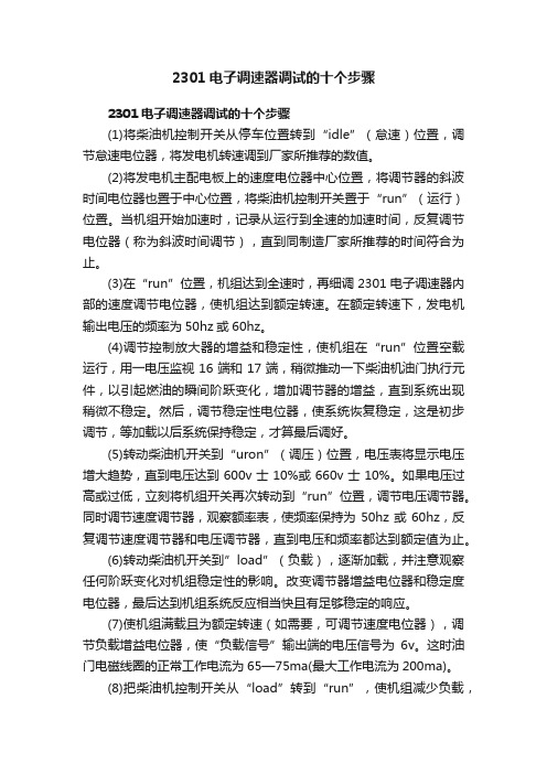
2301电子调速器调试的十个步骤2301电子调速器调试的十个步骤(1)将柴油机控制开关从停车位置转到“idle”(怠速)位置,调节怠速电位器,将发电机转速调到厂家所推荐的数值。
(2)将发电机主配电板上的速度电位器中心位置,将调节器的斜波时间电位器也置于中心位置,将柴油机控制开关置于“run”(运行)位置。
当机组开始加速时,记录从运行到全速的加速时间,反复调节电位器(称为斜波时间调节),直到同制造厂家所推荐的时间符合为止。
(3)在“run”位置,机组达到全速时,再细调2301电子调速器内部的速度调节电位器,使机组达到额定转速。
在额定转速下,发电机输出电压的频率为50hz或60hz。
(4)调节控制放大器的增益和稳定性,使机组在“run”位置空载运行,用一电压监视16端和17端,稍微推动一下柴油机油门执行元件,以引起燃油的瞬间阶跃变化,增加调节器的增益,直到系统出现稍微不稳定。
然后,调节稳定性电位器,使系统恢复稳定,这是初步调节,等加载以后系统保持稳定,才算最后调好。
(5)转动柴油机开关到“uron”(调压)位置,电压表将显示电压增大趋势,直到电压达到600v士10%或660v士10%。
如果电压过高或过低,立刻将机组开关再次转动到“run”位置,调节电压调节器。
同时调节速度调节器,观察额率表,使频率保持为50hz或60hz,反复调节速度调节器和电压调节器,直到电压和频率都达到额定值为止。
(6)转动柴油机开关到”load”(负载),逐渐加载,并注意观察任何阶跃变化对机组稳定性的影响。
改变调节器增益电位器和稳定度电位器,最后达到机组系统反应相当快且有足够稳定的响应。
(7)使机组满载且为额定转速(如需要,可调节速度电位器),调节负载增益电位器,使“负载信号”输出端的电压信号为6v。
这时油门电磁线圈的正常工作电流为65—75ma(最大工作电流为200ma)。
(8)把柴油机控制开关从“load”转到“run”,使机组减少负载,不用调节速度电位器,只调节调差电位器,使机组达到额定转速。
WOODWARD 2301D设置、操作手册

WOODWARD 2301D设置、操作手册26288 (Revision C)使用WOODW ARD 2301D进行柴油机无差速度调节控制,相关设置、操作如下:启动过程说明采用自动启动控制过程,由控制台控制全部过程,启动控制原理:通过识别柴油机由被动运转,转变到主动运转,实现启动过程自动控制,识别原理:风马达定速在点火速度以上,怠转速度以下,通过识别风马达达到点火速度后,柴油机会主动运转,并由调速器配合,控制到怠转速度,即认为启动成功,如果超时达不到怠转速度,认为启动失败。
硬件1. 开关输入控制1.1接线图WOODWARD 2301D 开关控制图1.2 启动控制描述1.2.1 系统通电,自检通过,符合启机条件1.2.2 28号端子同31号端子【停车】触点闭合1.2.3 28号端子同33号端子【怠转/额定】触点分开,其他控制触点分开1.2.4 启动风马达1.2.5 当转速达到点火转速后,柴油机点火主动运转1.2.6 当转速达到启动控制速度后,调速器开始调整油门,逐步控制到怠转1.2.7 当转速达到怠转速度后,关闭风马达,启动成功1.2.8 如果超时未达到怠转速度,则认为启动失败,执行停机过程1.3 运行控制描述1.3.1 闭合28号端子同33号端子【怠转/额定】触点(一直闭合), 调速器控制到额定转速1.3.2 28号端子同35号端子【升速】36号端子【降速】点动闭合,转速上升或下降1.4 停机控制描述1.4.1 打开28号端子同33号端子【怠转/额定】触点,等待发动机转速降到怠转速度后1.4.2 打开28号端子同31号端子【停车】触点,调速器控制到停车状态注意:不可将【停车】触点直接用于停车,因为可能在额定高转速下,直接切断油路,对发动机不利,所以必须在怠转低转速下,切断油路,使发动机熄火,达到停机目的。
不可将【停车】触点用于紧急停车,以防执行器被卡,达不到紧急停车目的。
注意:在不使用模拟线路控制时,应将模拟线路设置为不使用。
《重汽天然气发动机内部培训》PPT课件

OH1.2 Engine Controller
BARO
MAP
MAT ECT Oil Presssure Switch Cam Position Boost UEGO Fuel Meteri ng Control
Engine
RS232 P C or IS O K and CA N or J1708
Compressed Air
南
复
强
动
力 九、凸轮轴位置传感器(CAM)和曲轴位置(CNP)传感
有
限
器
公
司
曲轴位置传感器提供发动机转速信息,凸轮轴位置传感
器通知ECM哪一缸处于压缩过程,并发出点火时刻指令。
ECM只是在燃烧循环时给点火线圈供电。
济
南
复
强
动 力
十、点火线圈
有 限
ECM系统控制直接位于火花塞上的高能量点火线圈,不
公 司
济 南 复 强 动 力 有 限 公 司
济 南 复 强 动 力 有 限 公 司
曲线采集及分析方法
济 南 复 强 动 力 有 限 公 司
济 南 复 强 动 力 有 限 公 司
济 南 复 强 动 力 有 限 公 司
济 南 复 强 动 力 有 限 公 司
济 南 复 强 动 力 有 限 公 司
限
公
司
基准
口
高压燃料进 口
温度传感器
水循 环口
低压 燃料 出口
高压调节器是一个机械式 二 级 减 压 装 置 , 将 CNG 的 供 气 压 力 从 250bar 调 节 至 8bar 。 调 节 器 带 有 一 个 车 载燃料温度传感器,当燃料 温度低于容许限度时,用于 限制发动机功率以保护下游 燃料系统部件。
WB-GC-B说明书070530
定 义:
● 具有资格的人员: 在本使用说明书和产品的标牌上所出现的“具有资格的人员”是指
那些对设备的安装、操作构成及熟悉设备涉及的危险性的人员。
他们必须具备如下条件:
1. 他们经过培训通过了审定,能够按照制定的安全规范对设备进行通 电,断电清扫,对线路和设备进行接地和接线。
2. 经过培训,能按照制定的安全规范,正确使用和维护保护装置。
第 7 页/共 23 页
WB-GC-B 发电机控制柜说明书
2.柜体内设备
第二章 操作
A 图 2-2 如图 2-2,均按实际安装位置所示。A 为柜内设备正视图。
第 8 页/共 23 页
WB-GC-B 发电机控制柜说明书
3. 设备及元件介绍 如图 2-1 和 2-2 所示,其中所标注设备对应元件的名称如下:
额定频率:
50/60Hz
电气系统
3 相,3 线
系统接地
不接零
断路器
额定电流
2000AF/2000AT
额定电压
600V
短路电流
65KA
电动储能
保护单元
过流、短路、欠电压
操作及显示
面板具有操作及显示功能
控制功能
(1) 柴油机转速控制
频率稳态调整率:0—5%
频率波动率:0.5%
频率动态调整率:5%
频率稳定时间:3S
(2) 发电机电压控制
电压稳态调整率:0—2.5%
电压波动率:±0.5%
电压动态调整率:10%
电压稳态时5%
无功功率:小于 5%
(4) 发电机保护值
逆功率跳闸保护:7%
过电压跳闸保护:690V
欠电压跳闸保护:530V
过频率跳闸保护:54Hz
柴油发电机组控制系统

世界上第一台柴油机
世界上第一台柴油机诞生于1893年的德国。蒸汽机发明后,鲁道夫.狄塞尔(RUDOLF DIESEL)—一位德国皮革商的儿子,在慕尼黑技术大学上学时对“蒸汽机”表现出了极大的兴趣,在他34岁那年(1892)取得了把空气压进容器并且和煤粉充分混合直至被压燃而提供动力的机械装置的发明专利。第2年,位于德国奥古斯堡的MAN公司根据这一专利制造出了世界上第一台柴油发动机的原型机,并取名叫‘狄塞尔(DIESEL)’发动机。像所有的新生事物一样,狄塞尔发动机从诞生到不断完善经历了漫长的过程。狄塞尔先生在他55岁那年不幸逝世了,没有能够见到他发明的发动机装在汽车上。10年之后,MAN公司终于在柏林的汽车展览会上推出了第一台装在卡车上的狄塞尔发动机。后来,设在曼海姆的奔驰公司制造出了带预燃室的狄塞尔发动机,并且把它装在了自己的卡车上。直到1936年,也就是狄塞尔先生去世23年后,梅塞得斯——奔驰公司才制造出了第一台装有狄塞尔发动机的轿车。 直到今天,柴油机的英文名称仍然是‘DIESEL ENGINE’—‘狄塞尔’引擎。
2
电流互感器
电力仪表(多功能保护继电器)
1
4
3
测量回路和电力监视
发电机回路的保护
目的: 防止发电机过载损伤 切除发电机和发电机故障 发电机断路器和馈电用保护装置进行选择切除动作,并迅速切除汇流故障 发电机并联运行时,防止原动机损伤 内容: 发电机过载保护 发电机短路保护 发电机逆功率保护 发电机欠电压保护 自动卸载
将交流或直流发电机与柴油机曲轴同轴安装,就可以利用柴油机的旋转带动发电机的转子,利用‘电磁感应’原理,发电机就会输出感应电动势,经闭合的负载回路就能产生电流。
这里只描述发电机组最基本的工作原理。要想得到可使用的、稳定的电力输出,还需要一系列的柴油机和发电机控制、保护器件和回路。
2301A
WARNING警告Read this entire manual and all other publications pertaining to the work to be在安装、操作,或者维护本装置之前,认真阅读本手册的全部内容及其它有关的出版物。
performed before installing, operating, or servicing this equipment. Practice all检查所有装置、plant and safety instructions and precautions. Failure to follow instructions can 安全说明、预防措施。
不遵守安全规章,可能会引起严重的cause personal injury and/or property damage.人身伤害或财产损失The engine, turbine, or other type of prime mover should be equipped with an发动机,汽轮机,或者其它类型的原动机应配备一个超速(超温、超压在合适的地方)overspeed (overtemperature, or overpressure, where applicable) shutdown停车device(s), that operates totally independently of the prime mover control device(s)保护装置,该装置要独立于主控制设备之外,to protect against runaway or damage to the engine, turbine, or other type of prime以避免由于机-液调速器或电气控制、传动装置、燃油控制、驱动机构、mover with possible personal injury or loss of life should the mechanical-hydraulic联动或控制装置失效等引起的超速,造成机器损坏或人员伤亡。
2301A负荷分配型2301A电子调速器操作说明
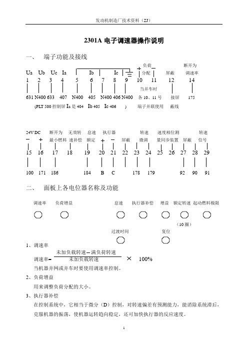
2301A电子调速器操作说明一、端子功能及接线负荷断开为U a U b U c I a I b I c分配屏蔽调速率1 2 3 4 5 6 7 8 9 12 14当并车时631 N400 633 407 N400 405 N400 406 N400 各10、11号接屏175 (PLT-500控制屏I a是404 I b 405 I c 406 ) 端子并联使用蔽线24V DC断开为无效转怠速执行器转速速度相位测转速最小燃料速补偿额定屏蔽微调量同步装置屏蔽信号16 17 18 21 23 24 25 29100 171 186 184 B C 178 179 92 90 91 二、面板上各电位器名称及功能调速率负荷增益怠速执行器补偿增益额定转速起动燃料极限(10圈)过渡时间复位1、调速率未加负载转速满负荷转速调速率= 未加负载转速100%当机器并网或并车时要使用调速率控制。
2、负荷增益用来调整负荷分配的大小。
3、执行器补偿在控制系统中,它相当于微分(D)控制,对转速偏差有预测能力,能消除系统滞后,克服机器的振荡,使机器运转趋向稳定,还可加快执行器的反应速度。
4、增益在控制系统中,它相当于比例控制(P),能够快速的达到控制目的。
一般在调整中首先要调整该电位器。
5、额定转速它是10圈的电位器,可快速调节;而其他电位器均是1圈的,均需缓慢调节。
6、动燃料极限当起动机器时,它可以限制燃料齿杆的位置极限。
另外,调整该电位器可设置所需执行器的最大位置。
7、过度时间表示的是从怠速到额定转速的过渡时间,通常将它顺时针旋到底,放到最大位置。
8、复位在控制系统中,它相当于积分(I)控制作用,对控制效果来说它能够消除系统的静态偏差。
一般的,积分时间越小积分作用越强,系统振荡越强;积分时间越大积分作用越弱,系统振荡越小。
我厂调试机器需要机器转速平稳,所以要削弱积分作用通常把它设置在5以上。
三、起动前初始设置1、额定转速电位器:逆时针旋到最小位置,控制屏上的转速微调电位器至于中间位置。
2301A产品简介
2301A 外形尺寸
执行器信号 0-200mA,标准,30-45Ω 温度限制 操作温度:-40ºC 至+85ºC 存放温度:-55ºC 至+105ºC 湿度限制 38ºC 时 95% 振动和冲击 可承受 5Hz 和 500Hz,4 倍于重力加速度的振动和 60 倍于重力加速度的冲击。 稳态转速带宽 为额定转速的 1%的±0.25 当选用负载感应设备时,允许与速度设定相匹配的额定负载的±5%的负载分配精度。
速度微调 外接一个电位计或数字式速度设定单 元,可以对原动机的速度进行远程微 调。
最小燃料控制 控制器上接一个开关可对原动机进行 最小燃料控制。此开关可用于一般的 停机操作。
转速信号失效保护电路 2301A 速度控制器通常监测速度传感 器信号。当速度信号低于某一设定最 小值时,控制器发出一最小燃油信号 给执行器,使发动机停机。当发动机 为慢拖动起动方式时,起机时外接一 个触点开关可以暂时取消速度信号失 效保护功能。
说明
速度范围 每个开关位对应一定的速度范围,共有四种范 围可选择:(基于速度齿盘的信号频率)
500-1500Hz 2000-6000Hz 1000-3000Hz 4000-12000Hz
速度感应 有效幅值:1~30Vac 。最大负载为:1KΩ/ 1Khz
外部速度微调 使用 100Ω 电位计速度调整量为:±5%
产品说明
82021Dcn
2301A 速度控制器
• 电源模式:低 压及高压型
应用
2301A 速度控制器用于柴油机、气体 发动机、蒸汽轮机及燃气轮机的速度 或负载控制。 2301A 提供等速模式的控制,通过外 接电位计也可进行有差调节。只要原 动机产生的功率满足负载的需要,等 速控制模式就可以保证原动机恒速运 行。 2301A 速度控制器与 Woodward SPMA 同步器、负载感应器及其他发电用 控制器兼容。任何时刻,这些控制都 可通过输入附加信号或 SPM 信号加 入到 2301A 控制器系统。 控制器的输出有正向动作型和反向动 作型两种,可控制一个单独的或两个 串联的执行器。高压型模块电源电压 为:88-132Vac 或 90-150Vdc;低压型 模块电源电压为:10-40Vdc。 2301A 还具有 4-20mA 速度设定输入 功能(见产品说明 02301)。
2301ALSSC中文手册

4
2301A –LSSC 速度负荷控制器中文手册
1. 综述
2301A LSSC 系列控制器是伍德沃德 2301A 系列控制器中的一种 它是在 2301A 速度控制器的 基础上增加了一个负荷信号处理单元 使之具有速度和负荷分配双重控制功能 该控制器输出毫安级直流电流控制信号 可以直接与伍德沃德生产的 UG EG 等系列电液执行 器或 ProAct 全电驱动执行器兼容 整个系统组合灵活 调整简便 可靠实用 被广泛地应用于 柴油机 汽轮机或燃气机等原动机发电机组的调速及并车控制 1.1. 定货信息 控制器的工作电源有两种类型: 高压型 90-150 Vdc 或 88-132Vac 低压型 24Vdc 控制器的输出电流可以有三种选择: 0-200mA, 或 0-20 mA, 0-400 mA 定货时用户既要考虑控制器适应的电源 还要考虑与之匹配的执行器的工作电流 然后 做出零件号的正确选择 具体零件号选择见下表 另外 针对不同燃料的原动机和不同主机厂的发动机 2301 A 都有不同的零件号 这里 主要列出通用性 柴油 气体发动机 控制器的零件号 汽轮机未列出 表 1. 2301A 速度及负荷控制器选型 低压型(20-40 Vdc) P/N(零件号) 执行器工作电流 9905-022 0-400 mA 9905-023 0-400 mA 9905-024 0-200 mA 9905-025 0-200 mA 9905-026 0-20 mA 9905-027 0-20 mA 9905-028 0-200 mA 9905-029 0-200 mA 9907-018 0-200 mA 9907-019 0-200 mA 9907-023 0-200 mA 9907-024 0-200 mA 9905/9907 系列 正向/反向动作 执行器级联/单个 Forward( 正向) 单个 Reverse( 反向) 单个 Forward 级联 Reverse 级联 Forward 单个 Reverse 单个 Forward 单个 Reverse 单个 Forward 单个 Reverse Forward 单个 Reverse 单个
- 1、下载文档前请自行甄别文档内容的完整性,平台不提供额外的编辑、内容补充、找答案等附加服务。
- 2、"仅部分预览"的文档,不可在线预览部分如存在完整性等问题,可反馈申请退款(可完整预览的文档不适用该条件!)。
- 3、如文档侵犯您的权益,请联系客服反馈,我们会尽快为您处理(人工客服工作时间:9:00-18:30)。
参数的调整
• 负荷增益调整 • 做此调整,必须先使发电机组工作在恒速、单 机运行模式。 • 准备一块万用表,用于测量控制器11(-)和 13(+)脚之间的负荷电压信号。 • 起机,发动机加满负,测量负荷电压信号,并 慢馒调大负荷增益,直至负荷信号达到6伏*。 如果加不了最大负荷,则按比例调低电位器; 比如,5%的负荷对应3伏的负荷信号电压。
故障判断
发动机起不了机,执行器没有开到起动位置
•
• • 可能的原因:电源极性接反了或没给电源 解决方法:测量控制器的输入脚16(+)和17(-), 检查电源电压。 驱动器或执行器对输入信号没有响应 测量控制器20(+),21(-)脚上的电压输出,, 如果没有信号,但执行器没动作,则查一下执行 器的电气接线,一般执行器的内阻<50Ω。 如果是全电执行器,也可能是驱动器的问题。
2301A控制器电气接线图
2301A控制器电气接线图
速度PID调节控制(原理框图)
控制功能说明
• 借助于磁电式转速传感器,2301A控制器实 时跟踪发动机瞬间的转速变化 通过与设定转 速的比较,产生速度偏差信号控制器采用 PID(比例积分微分)控制。及时准确地输出纠 正控制信号,最终由执行器去调节发动机燃 料的增加或减少。通过闭环回路,达到发动 机的速度控制。
面板调整电位器的中文解释 • RATED SPEED-额定速度设定;顺时针为增大 方向 • ACTUATOR COMPENSATION-执行器补偿调 整,相当于速度PID中的微分调节 • GAIN-速度控制的增益调整,影响动态过程的调 速率幅度,顺时针为增益增大方向 • RESET-速度控制的复位调整,影响动态过程的 恢复时间;顺时针为时间增大方向 • START FULE LIMIT-起动限油,调整范围;执 行器输出的25%-100%,顺时针为增大方向
故障判断
发动机起不了机,执行器没有开到起动位置
• 最小供油开关打开了 • 检查控制器17脚上的短接片是否被打开了,15 脚(-)和17脚之间的电压应为:20-4OVdc • 速度传感器信号有问题,信号丢失保护电路起作 用 • 按要求检查转速传感器的接线及安装情况。
故障判断
发动机起不了机,执行器没有开到起动位置
控制功能说明
• 速度控制有两种模式:有差调节(DROOP)和恒速 控制(ISO)恒速模式:发动机的稳定转速不受负 荷变化影响。有差模式:发动机转速随负荷的增 加而下降。 • 有差选择开关(端脚14)和发电机C、B辅助触点呈 串联关系,两个触点都闭合,既选择恒速控制; 只要一个触点打开,即选择了有差调节。实际上, 控制器内部有一继电器,它受上述触点的控制, 负责控制器内部的有差调整电路和负荷分配电路 之间的切换。
•
故障判断
发动机起不了机,执行器没有开到起动位置
• • •
• • •
起动限油值太低 调大起动限油值,直到发动机能起来 执行器或连杆有问题 检查执行器及连杆的安装和动作情况。问题可能是供油、 旋向、零件磨损等情况 控制器20和21脚之间没有控制信号输出 1、停机,拆掉20、21脚上的连线,检查与之相关的设 备的接线情况,有无短路或接地 2、如果一切正常,则合上18脚上的开关,启用评比信 号丢失功能,短接23、24脚,检测20、22脚的电压输 出,对于正向输出的控制器应为18-22V;反向输出为01V。
2301A-LSSC输入输出脚的定义
• • • • • 端脚14:有差调节触点开关输入端 端脚15、16:电源输入负极、正极 端脚17:最小限油开关输入 端脚18:屏蔽转速信号丢失功能选择开关 端脚19:怠速/额定速度选择开关输入,开关闭 合为额定速度工作方式 • 端脚20、21:到执行器的控制输出 • 端脚22:执行器和外接转速微调位器的屏蔽线 接线端 • 端脚23、24:转速微调电位器接线端
起机步骤
• 3、检查转速传感器的接线、齿盘间隙 (0.5~1.0mm) • 起机过程:对应最小控制转速,传感器信号幅值 应大于lVac(交流有效值)。 • 最小控制转速确认:转速范围下限的5%为控制器 能识别的最小值。比如,转速信号设定范围 为:2000~6000Hz,则最小识别频率 为:20×5%=100Hz,由此计算出对应的最小控 制转速。当起机拖动转速达到该值,控制器即投 入控制。
• 控制器23、24之间开路 • 如果不用外部电位器微调,应保留这两脚之间的 短接片。 • 速度微调阻值不合适 • 断电,检查外部微调电位器的阻值,应小于 100Ω。 • 2301控制器坏了 • 更换同一型号的控制器
故障判断
• • • • • • • • • • 斜坡发生器(RAMP)时间调整太短,控制器反应过快 适当增大(顺时针)斜坡发生器,减小升速率 额定速度设定太高 逆时针调小额定速度电位器 控制PID参数调整不当 适当增大增益,提供相应速度 驱动器失去控制能力 检查驱动器电源 发动机问题 确认齿条连杆的状态,有无卡死现象,检查超速保护装 置
负荷分配控制
负荷分配控制
• 控制器内部的负荷控制由两部分电路完成: 负荷传感器和匹配电陈路,来自发电机的 CT、PT信号首先通过控制器内部的负荷传 感器可转换为能反映发电机负荷大小的06Vdc电压信号,调整面板上的负荷增益电 位器,可以改变此电压值,即标定机组的 最大负荷;最后结合匹配电路完成有差调 节或恒速控制模式下的并车或并网中的负 荷分配控制。
面板调整电位器的中文解释
2301A-LSSC输入输出脚的定义
• 端脚1、2、3:三相电动势PT的输入;输入范围 9O~24OVac • 端脚4、5:A相电流CT的输入;输入范圃 0~5A。 • 端脚6、7:B相电流CT的输入,输入范既 0~5A。 • 端脚8、9:C相电流CT的输入,输入范融 0~5A。 • 端脚10、11、12:负荷分配线 (+ -,屏蔽线), 并接到其他同类控制器的负荷分配线 • 端脚13:负荷信号测试端(+),与脚11(-)结合测
旋钮的功能和调节
• 起动限油-调节范围: • 执行器输出的25%~100%,调节面板上的 起动限油电位器,选择适当的起机燃料供 应量,可以防止发动机起机冒黑烟,改善 起机排放,提高系统燃料的经济性。起动 限油的低限为:执行器输出不低于3Vdc发 动机一旦投入正常运行,起动限油功能会 自动地被速度PlD控制取代。
旋钮的功能和调节
• 转速信号监视功能的暂时屏蔽 • 控制器端脚18和电源输入正(端脚16)之间可 接一开关。起机时,短暂闭合此开关可暂 时屏蔽速度信号丢失保护功能,使控制器 能在没有转速信号的情况下起机;打开触 点开关,立即恢复速度信号监测功能。利 用此功能可以调节起机限油值的大小。
旋钮的功能和调节
2301A-LSSC输入输出脚的定义
• 端脚25、26:同步控制信号输入;可接收 ±1.5Vdc的信号,对应的调节范围为±1%; 如果同步的输入±5Vdc的信号,速度调节 范围为:±3.3%。 • 端脚27:为同步输入线和速度信号输入的 屏蔽线接线端。ቤተ መጻሕፍቲ ባይዱ• 端脚28、29:转速信号输入端,接收范围: 1-30Vac(交流有效值)
起机步骤
• 如果电压值很小,几乎为零 则慢慢调大额 定速度电位器,直到执行器刚好有增大到 头的趋势。 • 如果电压值很大,则慢慢调小速度电位器, 直到执行器有输出最小的势头。 • 然后继续慢慢调电位器 使执行器的电压处 于最小和最大之间,当电压信号变化缓慢 至停,说明此位置比较接近理想的额定速 度。 • 当发动机运转时,稍微再调一下额定电位 器 即可达到额定转速。
参数的调整
• 低怠速调整 • 打开怠/额定速度开关,选择怠速运行 • 先把怠速电位器顺时针调到最大时,发动机速 度应接近额定速度 • 然后逆时针调,直到规定的怠速位置 • 斜坡发生器(RAMP) • 适度调节斜坡发生器,以使主机从怠速向额定速 度过渡时过冲最小。起机时,可将其位置调到最 大,然后再回调。
起机初始设置
• 有差调节逆时针旋到最小位置。 • 补偿调整电位器-对于柴油机、燃气机或燃 油喷射的汽油机,设置在刻度2;如果是化 油器式燃气发动机或汽油机、汽轮机,调 在刻度6。 • 起动限油-顺时针调到接近最大。 • 确认执行器的线己接好。
起机步骤
1、给控制器上电 2、预调额定速度; • 如果没有信号发生器,请将额定速度电位器至于 最小位置。 • 如果使用信号发生器,需要计算出对应额定速度 的频率值 然后把此频率的正弦波信号输出到控制 器的28、29脚,来模拟转速信号。同时把万用表 接到控制器的20、21脚,用直流电压档测其到执 行器的电压信号。
天然气发电机培训班
(2301速度及负荷控制器 、驱动器、执行器)
伍德沃德 2301速度及负荷控制器
伍德沃德2301速度及负荷控制器
低压型:24Vdc 控制器的输出电流有三种选择:0-200mA, 或0-20 mA,0-400 mA 。
面板调整电位器的中文解释
• DROOP-有差调整;调整范围:额定速度 的0-10%,顺时针为增大方向 • LOAD GAIN-负荷增益调整,并车时提供机 组最大的负荷标定。顺时针为减小方向 • LOW IDLE SPEED-怠速调整;调整范围: 额定转速的30%-100%,顺时针为增大方向 • RAMP TIME-斜坡发生器;表示怠速和额定 工况之间的过渡时间,顺时针为增大方向
参数的调整
• 设定转速调整 • 如果发动机运行稳定,(如果使用外接微调电位器,请 将之调到中间),然后慢慢调整额定转速电位器,直到 发动机运行在要求的额定转速上 • 执行器补偿调整 • 如果在初始设定位置时,发动机的动态稳态性能都挺好, 则无须再调执行器补偿电位器。 • 如果仍有慢速游车,稍微增大补偿(顺时针调),然后重 新调整增益和复位,直到发动机稳定。 • 如果是快速游车,稍微减小补偿(逆时针调)。必要的话, 关到最小(当发动机发生扭振引起油泵齿条过度运动时)
参数的调整
