AS1735.18澳大利亚-新西兰标准
澳洲电气标准
澳洲电气标准
澳大利亚的电气标准由澳大利亚标准协会(Standards Australia)制定和管理。
这些标准用于确保电气设备、系统和安装的安全性、性能和互操作性。
以下是一些澳大利亚电气领域的主要标准:
1.AS/NZS 3000:《澳大利亚/新西兰电气安装规范》(AS/NZS
3000),通常称为电气安装标准,规定了电气设备和系统在澳大
利亚和新西兰的安装要求。
这个标准包括对电线、电缆、开关、
插座、照明、电气板、接地等方面的详细规定。
2.AS/NZS 3008:《澳大利亚/新西兰电气装置- 电线和电缆的
选择、安装和维护》(AS/NZS 3008),规定了电线和电缆的选择、安装和维护的要求。
3.AS/NZS 3017:《澳大利亚/新西兰电气设备- 电气安全与性
能要求》(AS/NZS 3017),规定了电气设备的电气安全和性能要
求。
4.AS/NZS 3760:《澳大利亚/新西兰电器安全检验和测试- 移
动电器检验和测试》(AS/NZS 3760),规定了对移动电器进行安
全检验和测试的程序。
5.AS/NZS 3100:《澳大利亚/新西兰电气设备- 安全要求》
(AS/NZS 3100),规定了电气设备的一般安全要求。
这些标准覆盖了从电气设备设计和生产到安装和维护的各个方面。
澳大利亚的电气专业人士、工程师、设计师和电工在进行相关工作时通常需要遵守这些标准,以确保工程的安全性和符合法规要求。
标准
可能会定期更新,因此建议查阅最新版本的相关文件。
澳大利亚和新西兰家用电器法规标准体系
澳大利亚和新西兰家用电器法规标准体系中国是澳大利亚第一大贸易伙伴、出口市场和进口来源国,澳大利亚国内没有自己的家电制造企业,从大家电类的冰箱、洗衣机和空调等到小家电类的电水壶,吸尘器等产品都依赖进口。
澳大利亚标准与IEC标准的协调一致性。
澳大利亚的标准以“AS”开头,澳大利亚与新西兰的联合标准以“ AS/NZS”开头。
澳大利亚的标准与新西兰的标准基本与IC一致(目前澳大利亚的标准有333%完全与IEC标准一致),有些存在一些国家差异,例如:对于电源电压的要求是240V(单相)415V(三相)50Hz;由于所处的地理位置,某些产品的标准(如冰箱、空调)规定应按热带气候来考虑等。
澳大利亚和新西兰推行统一的标准和认证的相互认可,产品只要取得一个国家的认证后就可在另外一个国家销售。
澳大利亚认证主要包括电气安全、电磁兼容及能效标签三个方面产品电气安全认证澳大利亚没有统一的安全认证标志,各个州或地区都先后以立法的形式规定了对电器产品的管理方法,各个州或地区关于电气安全立法的内容基本一致电气产品分为强制申报产品和非强制申报产品。
电磁兼容性要求绝大部分电气电子产品都必须符合电磁兼容性EMC框架文件的要求,其目的是保护无线电通讯频段的资源,减少电器产品的辐射并确保电器产品的设计不会被电磁辐射所干扰。
其规定的实施制度有点类似于欧洲的EMC指令,即按照基于 CISPR文件的标准,通过测试或建立技术结构文件后,允许生产商进口商进行自我声明并在产品标示C-tick标记以表示符合性。
能耗标签改善器具和设备的能效是澳大利亚政府的努力目标,《国家温室大纲》中明确指出:通过扩展和提高现存的标贴和最小能源性能标准的有效性,来促进家用器具及商用和工业用设备的能效的改善。
除安全要求和EMC要求外,许多电器产品均需要具备能耗标贴方可在澳洲市场出售,例如:冰箱和冷柜、干衣机、空调、洗碗机、洗衣机等等。
申请人必须向监控机构提交申请表并附上完整正确的测试报告及能耗标签的样本。
rcm认证标准

rcm认证标准
RCM(Regulatory Compliance Mark)是澳大利亚和新西兰的一种法规符合标志,用于指示产品符合澳大利亚和新西兰相关的安全电气设备要求。
它扩展了原来的C-Tick标志(澳大利亚)和A-Tick标志(新西兰),统一了两国的产品合规性认证标准。
RCM认证的标准是由澳大利亚电信和媒体管理局(ACMA)制定和管理,主要参考以下相关标准:
1. AS/NZS 4417.2:2012 - 发射率、不协调和互模干扰射频辐射验收规范
2. AS/NZS 60950.1:2015 - 信息技术设备的安全性
3. AS/NZS CISPR 1
4.1:2020 - 家用电器、电动工具和类似设备的无线电骚扰特性
4. AS/NZS 4268:2017 - 广播接收机和相关设备的射频辐射特性
5. 等等
RCM认证标志的使用要求:
1. 产品在澳大利亚和新西兰市场销售前,必须取得RCM 认证并贴有RCM标志。
2. 产品的测试和评估必须由澳大利亚认可的第三方实验室进行。
3. 经授权的电信标志,例如A-Tick、C-Tick在特定的时间段之后被淘汰,产品需要植入RCM标志。
需要注意的是,为了获得RCM认证,还需要了解并满足澳大利亚和新西兰相关的法规和技术规范要求。
具体的认证过程和要求可能因产品类型和领域而有所不同,建议在申请RCM认证之前,咨询相关机构或专业认证机构以获取准确的信息。
澳大利亚和新西兰- C-Tick
澳大利亚和新西兰认证澳大利亚的标准机构为Standards Association of Australian,澳大利亚的标准以“AS”开头,澳大利亚与新西兰的联合标准以“AS/NZS”开头。
澳大利亚的标准与新西兰的标准基本与IEC一致,同时存在一些国家差异。
澳大利亚和新西兰推行标准的统一和认证的相互认可,产品只要取得一个国家的认证后就可在另外一个国家销售。
1.产品安全认证澳大利亚没有统一的安全认证标志,各个州或地区都先后以立法的形式规定了对电器产品的管理方法。
虽然名称及颁布的日期不尽相同,各个州或地区关于电气安全立法的内容基本一致。
电气产品分为强制认可(prescribed product)和非申报产品(Non-prescribed product)。
∙强制认可-申报产品: 主要有56大类产品, 目录见, 主要为普通家用电器和标准附件. 产品符合安全标准后获取认可证书, 产品必须标记认可标志. 认可标志是由一个代表颁发认可的洲的字母加上由管理机构分配的数字组成.例如N012345,N指新南威尔士,后面数字为证书号.一般证书五年有效.∙非申报产品: 未列入申报产品目录的产品为非申报产品,认可不是强制的,但同样必须符合相应的安全标准,也可以自愿申请认可,认证机构可以颁发适宜性证书.认可标志例如是CS12345N,CS指适宜性证书,N指新南维尔士,中间数字为证书号.2.能耗标签大部分州与地区对白家电与家用空调的能耗都有类似的强制要求,各个州的强制认证产品目录不尽相同。
任何一个州的登记在其他的州与地区也同样有效。
能耗要求适用于下列家用电气,申请人必须向监控机构提交申请表并附上完整正确的测试报告及能耗标签的样本。
测试报告必须由经认可的实验室出具,自签发日起三年内有效。
∙冰箱和冷柜;∙干衣机;∙空调;∙洗碗机;∙洗衣机等等.3.电磁安全性要求在澳大利亚电磁兼容性由ACA(Australian Communications Authority)监控,在澳大利亚的EMC体系下,产品分为三类,供应商在销售二、三类产品前必须在ACA注册申请使用C-TICK标志。
澳洲,新西兰龙头标准

1.3.9厨房洗涤槽水龙头
指设计为打开和关闭到厨房的洗涤槽,准备食物或洗碗环境的水流的龙头.
1.3.10洗衣机龙头
指设计为打开和关闭到洗衣机或洗手间的洗涤槽的水流的龙头.
1.3.11一致龙头
一种水平移动的龙头.
1.3.12混合式龙头(非恒温)
2.3不锈钢……………………………………………………………………………10
2.4塑料材料…………………………………………………………………………10
2.5塑料和合成橡胶材料……………………………………………………………10
2.6其它材料…………………………………………………………………………10
第3節设计及生产
1.3.20起皱系数
成品表面范围与测试表面相除比率.
1.3.21感应龙头
无须物理操作的龙头.
1.3.22角阀
一种有入水和出水连接的龙头.它通常装有一个松动的链接阀,只允许一定方向的水流.
1.3.23龙头主体
一个龙头或龙头组件的部分,包括入水口和出水口连接.
1.3.24龙头本体
龙头组件的一部分,可以移动,含有关闭装置.
注意:符合澳大利亚认证在澳洲必须进行,而在新西兰则不需要.
1.2参考文献
本标准参考文献表在附录B中列出.
1.3定义
为本标准的需要,本标准使用AS/NZS3500.0中规定的及下述定义.
1.3.1基座螺母
保持表面安装龙头的螺母.
1.3.2浴室面盆龙头
指设计为打开和关闭到面盆以洗手或洗脸的水流的龙头.
1.3.3符合认证
(f)对于龙头和压力敏感式组件应分别包装,最大操作压力应清楚标明在包装上,标签上或说明书上.
缆绳 澳大利亚标准

在澳大利亚,缆绳的标准是由澳大利亚标准(AS)所规定的。
具体来说,AS 1187.1-2009和AS 1187.2-2009这两个标准规定了缆绳的分类、标记、性能要求和测试方法等内容。
根据AS 1187.1-2009标准,缆绳按照其强度等级(即能够承受的最大拉力)被分为五类,分别是:
1. 低强度缆绳(Low strength):强度等级低于33.3kN(约为3.3吨)。
2. 中等强度缆绳(Moderate strength):强度等级为3
3.3kN至66.7kN(约为3.3吨至6.7吨)。
3. 高强度缆绳(High strength):强度等级为66.7kN至133.4kN (约为6.7吨至13.3吨)。
4. 超高强度缆绳(Super high strength):强度等级为133.4kN 至266.8kN(约为13.3吨至26.7吨)。
5. 特高强度缆绳(Extra high strength):强度等级超过26
6.8kN (约为26.7吨)。
此外,根据AS 1187.2-2009标准,缆绳还应满足某些特定的性能要求,例如耐磨性、耐腐蚀性、柔韧性等。
这些要求是根据具体的使用环境和需求来确定的。
在选择缆绳时,需要根据具体的使用场景和需求来选择合适的类型和规格。
例如,在海上石油平台或大型船舶上需要使用高强度、耐磨、耐腐蚀的缆绳;而在建筑工地或小型船舶上则可能需要使用轻便、柔韧的缆绳。
总之,在选择缆绳时需要根据具体的使用环境和需求来选择合适的类型和规格,并确保其符合澳大利亚标准(AS)的要求。
澳大利亚新西兰玩具安全标准

澳大利亚新西兰 玩具安全标准
,a click to unlimited possibilities
汇报人:
汇报时间:20X-XX-XX
添加目录标题
澳大利亚新西兰玩具安全 标准概述
澳大利亚新西兰玩具安全 标准的测试要求
澳大利亚新西兰玩具安 全标准的合规性评估
澳大利亚新西兰玩具安 全标准对企业的意义
和检测程序
标准在澳大利亚和新西兰两 国的玩具市场上得到了广泛
的应用和认可
澳大利亚新西兰玩具安全标准的测试 要求
物理安全性测试
拉力测试:模拟玩具被拉力, 检查是否损坏或破裂
扭力测试:模拟玩具被扭力, 检查是否损坏或破裂
挤压测试:模拟玩具被挤压, 检查是否损坏或破裂
跌落测试:模拟玩具从一定 高度跌落,检查是否损坏或 破裂
关注行业动态,了解最新的玩具安全标准和法规变化 建立内部培训机制,定期对员工进行培训,提高员工的专业水平和安全意 识
YOUR LOGO
THANK YOU
汇报人: 汇报时间:20X-XX-XX
评估标准
评估内容:包括玩具的物理、 化学、生物、电气等安全性 能
玩具安全标准:符合澳大利 亚新西兰玩具安全标准
评估方法:采用实验室测试、 现场检查等方式进行评估
评估结果:评估结果分为合 格、不合格、整改后合格等
几种情况
Hale Waihona Puke 评估方法检查产品是否符合标准要求 测试产品的安全性能 评估产品的标签和说明书
检查产品的生产过程是否符合标准要 求
应稳定
定期检查:定 期对供应商进 行质量检查, 确保原材料质
量符合标准
加强沟通:加 强与供应商的 沟通,及时了 解原材料质量 情况,发现问
asnzs 4911-2003
ASNZS 4911-2003是什么?1. 澳大利亚和新西兰标准AS/NZS 4911-2003是一项涉及工程结构用的玻璃的标准。
这项标准规定了玻璃在建筑和土木工程中的设计和安装要求,包括了玻璃的质量和强度等指标。
该标准涵盖了各种类型的玻璃,如钢化玻璃、夹层玻璃、双层玻璃等。
2. 该标准的发布旨在规范工程结构中玻璃的使用,并保证其质量和安全性,以保障建筑和土木工程的稳定性和可靠性。
它也为建筑设计和施工人员提供了一套权威的指导,确保他们在使用玻璃材料时能够符合相应的标准和要求。
3. 标准的内容主要涉及玻璃的设备和安装要求、玻璃的强度和稳定性测试、以及对特定玻璃材料的具体要求等内容。
通过实施这些规定,可以确保使用的玻璃材料能够符合建筑结构的要求,并且能够在各种条件下保持稳定和安全。
4. ASNZS 4911-2003是根据最新的技术和工程要求制定的,其内容经过了充分的科学论证和实践验证,因此具有很高的权威性和可靠性。
作为澳大利亚和新西兰的标准,它已经被广泛地应用于各种类型的建筑和土木工程项目中,对于维护工程结构的安全性和稳定性起到了至关重要的作用。
5. ASNZS 4911-2003标准的发布对于建筑和土木工程领域具有重要的意义。
它为工程设计和施工提供了具体的指导,确保了使用的玻璃材料的质量和安全性,保障了工程结构的稳定和可靠。
建议在进行工程结构设计和施工时,要严格遵守ASNZS 4911-2003标准的规定,以确保工程质量和安全。
ASNZS 4911-2003标准的重要性ASNZS 4911-2003标准的发布对于建筑和土木工程领域具有重要的意义。
它在工程结构中玻璃的使用方面提供了明确的指导,确保了玻璃材料的质量和安全性,从而保障了工程结构的稳定和可靠。
以下是标准的重要性:1. 维护工程结构的安全性和稳定性作为一项涉及工程结构用的玻璃的标准,ASNZS 4911-2003的发布和实施,有助于维护工程结构的安全性和稳定性。
AS1735.18澳大利亚-新西兰标准

AS/NZS 1735.18:2002澳大利亚/新西兰标准电梯,自动扶梯和自动人行道第18节:自动控制的私人住宅用乘客电梯前言这个标准是由澳大利亚标准和新西兰标准委员会ME-004共同制定的,电梯安装,用来替代标准AS1735.16-1993,即是:电梯、自动扶梯和自动人行道,第16节:采用自动控制的带限制功能的乘客电梯。
制定这个标准的目的是为在私人住宅区安装小型、低速乘客电梯提供帮助。
标准中使用了“提供信息的”这个单词,主要是用来定义所采用的附录的应用场合。
一个“提供信息的”附录只是用来提供信息或者参考。
内容第一节总章1.1 范围 (6)1.2 参考文献 (6)1.3 定义 (7)第二节设计限制2.1 速度 (8)2.2 行程 (8)2.3 额定负载 (8)2.4 轿箱尺寸 (8)2.5 安全因子 (8)第三节材料3.1 概要 (9)3.2 耐久性 (9)第四节驱动机械4.1 概要 (10)4.2 轴及其附属部分 (10)4.3 驱动方向 (10)4.4 手动操作 (10)4.5 设备固定 (10)第五节悬挂及其支撑系统5.1 方式 (12)5.2 钢索 (12)5.3 链条 (15)5.4 齿轮齿条 (15)5.5 螺杆驱动 (15)5.6 液压 (16)第六节井道6.1 支撑结构 (17)6.2 井道封装 (17)6.3 井道表面 (17)6.4 轿箱顶部超行程 (18)6.5 轿箱间隙 (18)6.6 地坑不能超过建筑最底层 (20)第七节导轨7.1 规定 (22)7.2 长度 (22)7.3 导轨及其固定物 (22)7.4 导轨偏移 (22)第八节导轨器8.1 概要 (23)8.2 滚子导轨器 (23)第九节缓冲器9.1 底部缓冲器 (24)9.1 顶部缓冲器 (24)第十节安全钳10.1 规定 (25)10.2 材料 (25)10.3 结构 (25)10.4 执行器 (25)10.5 释放 (25)10.6 性能 (25)第十一节配重块11.1 概要 (26)11.2 防护 (26)第十二节轿箱12.1 框架 (27)12.2 封装 (27)12.3 入口数量 (27)12.4 轿箱入口安全保护 (27)12.5 高度 (28)12.6 轿箱顶 (28)12.7 通风 (28)12.8 抢救手段 (28)12.9 轿箱底防护 (29)第十三节轿厢门13.1 层站门规定 (30)13.2 类型 (30)13.3 宽度 (30)13.4 高度 (30)13.5 建造 (30)13.6 开门力 (30)13.7 层站门自锁 (30)13.8 门铰链上光 (31)第十四节门锁和门开关14.1 轿箱 (32)14.2 停层 (32)第十五节控制装置15.1 位置 (34)15.2 操作控制按钮 (34)15.3 可逆型接触器 (34)15.4 操作回路 (34)15.5 防爬调平装置 (35)15.6 轿箱入口阻碍物传感器控制器 (35)第十六节电气16.1 电源 (36)16.2 配线 (36)16.3 回路制动器或开关 (36)16.4 门锁回路 (37)16.5 电机防护 (37)16.6 停层开关 (37)16.7 限位开关 (38)16.8 反相继电器 (38)16.9 安全钳开关 (38)16.10钢索或链条开关 (38)16.11井道挡板开关 (38)16.12安全阀测试电闸 (39)16.13地坑停层开关 (39)16.14滑轮或平台停止开关 (39)16.15闭锁装置开关 (39)16.16支撑螺母安全开关 (39)第十七节照明17.1 常用照明 (40)17.2 紧急照明 (40)17.3 地坑和顶部照明 (40)17.4 控制设备照明 (40)第十八节通讯18.1 规定 (41)18.2 可到达性 (41)18.3 电话系统 (41)18.4 声音报警 (41)第十九节公告19.1 载重牌 (42)19.2 标示牌 (42)19.3 紧急指示 (42)附录A 维修保养 (43)B 电梯类型选择指南 (44)澳大利亚/新西兰标准电梯,自动扶梯和自动人行道第18节:自动控制的私人住宅用乘客电梯第一节总章1.1 范围这个标准是特别为安装在私人住宅区的自动控制的小型低速乘客电梯制定的,定义在标准AS 1735.1中。
(建筑工程安全)ASNZS澳大利亚新西兰标准建筑用安全玻璃材料精编
(建筑工程安全)ASNZS_澳大利亚、新西兰标准建筑用安全玻璃材料AS/NZS2208:1996澳大利亚、新西兰标准建筑用安全玻璃材料StandardsAustraliaStandardsAustralia是壹所成立于1922年的独立的非营利机构。
它是澳大利亚的最高标准机构。
其宗旨是将个人和团体引向壹个共同的目标——为提高生活质量和工业效率而将澳大利亚标准确立为产业和服务的国家标准。
StandardsNewZealand新西兰的国家标准机构始建于1932年。
新西兰标准理事会是负责产品标准的权威机构。
该标准理事会于1988年根据标准法案建立StandardsNewZealand.Australian/NewZealandStandards根据StandardsAustralia和StandardsNewZealand之间的合作合约,工业、政府、消费者和其它部门的专家成立委员会筹备起草Australian/NewZealandStandards。
其公布的标准要求均经过各界代表的壹致同意,且考虑了其它意见。
它反映了科学和工业的最新经验成果。
Australian/NewZealandStandards于公布后因科技的发展不断被审核和修改。
国际合作StandardsNewZealand和StandardsAustralia均于努力使他们的观点被世界接受且从国际标准中吸收最新成果。
其职责关键于于帮助地方工业于国际市场上竞争。
俩家机构均是国际标准组织(ISO)和国际电子技术委员会(IEC)的成员。
会员和信息StandardsAustralia和StandardsNewZealand的成员可获得壹系列的服务,包括:国际和地方标准发展的最新信息,优先获得最新的出版物和信用透支。
StandardsAustralia于悉尼和墨尔本的信息中心,StandardsNewZealand于威灵顿的总部同时也提供澳大利亚、新西兰以及海外可适用的标准信息。
AS1735.1澳大利亚电梯标准(中文部分40-49)

附录AEN81在澳大利亚的应用变更(标准的附录)附录陈述了EN81在澳大利亚应用上的差异。
条款差异1.1 去掉‘链’1.2 增加如下注意事项:注意:AS1170.4应考虑地震条件5.1.3(新) 增加如下条款:5.1.3通道层站入口应提供至少1000mm的宽度,40-49页所有的门,窗户和能开关的设备,以及所连接在机房和电梯井道之间的孔都不能认为是通风方式。
通风要求被设计成能够控制的温度,其最高温度为34℃,以下要求适用于机房温度超过43℃时:(a)住楼梯平台或建筑入口附近的发声报警器应当报警,直到机房有人工重新操作时才停止报警。
(b)报警应当发生在经常惹人注意的场所,且这场所有一套能确认机房所在位置的系统。
(c)电梯应当能停止在一个平台让乘客离开,只有当机房内温度下降到43℃以下时才能重新正常运行。
任何机械的通风设施都应认为是电梯安装的一部分,且其从电梯断路器的线路旁边通过电气连接到电梯主机,最重要的是人工操作开关应当经过自动调温装置,使得机械通风设备能够被维修工操作。
6.3.7设备的搬运,围井出口门应使得最大的设备部件能被搬移到由电梯提供的标准或能适应其他机械搬运的方式。
机房一提供吊钩来使得最大设备元件能方便的搬运。
以下应用于楼房的顶板(a)盖板安装上铰链,当条件致使铰链不可行时可使用可移动的面板,松散的或可拆分的单面板或多面板结构的盖子,这种盖子能通过围井出后对角的坠落,假设把金属铰链安全装置设计成能维持降落盖板的状态,且这种装置已安装于这种自由部分之下时可使用。
(b)盖板的提升装置应设计成有助他们吊运的装置。
(c)底部或顶部的围井出口应当能直接消除人被拌倒的危害,以及能维持6kpa负荷的能力(d)当围井出口打开时,应有适当的警戒装置。
(e)围井出口盖板在不用时应被存放起来6.4.1.2 把“波形钢板”改成“网纹钢板”。
6.4.2.1 删除“2句和3句”6.4.3 删除整个条款。
7.1 用以下的取代第三段:(a)门与框架之间(b)门与地坎之间设有框架的石块和混凝土的入口(c)多路入口的门扇之间,门与地坎之间的垂直距离不超过9.5mm7.2.3.3 1.用一下的代替第一段:门扇轿厢或厅门的玻璃所要求的抗强度标准来执行,此时不损坏玻璃。
强光拒止器相关标准
强光拒止器相关标准
强光拒止器通常用于防止由强光引起的视觉不适或者损伤。
这类产品可能涉及防护眼镜、防护窗帘、遮阳篷等。
虽然不清楚您指的具体是哪种类型的产品,但以下是一些可能与之相关的通用标准:
1. ANSI/ISEA Z87.1: 标准涵盖了防护眼镜等眼睛和面部防护装置的性能和测试要求。
它涵盖了针对防护眼镜的基本要求,包括光学性能、冲击防护等。
2. ISO 12312-1:2013: 该标准涵盖了太阳镜的要求,包括光学性能、紫外线保护等。
3. AS/NZS 1337: 澳大利亚和新西兰标准中定义了一般眼和面部保护装置的要求。
请注意,针对特定产品种类的标准可能会有所不同。
因此,在寻找强光拒止器相关标准时,最好参考您所在地区的具体法规和标准组织的指南。
澳大利亚、新西兰瓦楞纸箱测试标准

澳大利亚、新西兰瓦楞纸箱测试标准2002──瓦楞纸板平压强度测试瓦楞纸板平压强度测试标准是由联合技术委员会起草的,专门针对纸浆和纸张的测试。
是纸浆和纸张测试方法(AS/NZS1301)的一部分。
该版本替代旧标准:AS1301.429s-1989和NZS1301.429s-1989。
该标准用于测试瓦楞纸板的抗压强度。
适用于三层或单面瓦楞纸板,但不适用于测定五层瓦楞纸板的抗压强度。
(注:三层瓦楞纸板楞型变形可能发生于以下两种情况:当压力不能从纸板边缘释放时,楞峰变平,从而导致楞型遭到破坏;当压力能从纸板边缘释放时,楞峰变平,表层面纸移位,使芯纸歪斜或卷曲。
五层瓦楞纸板受压时楞型遭到破坏,通常是由于中间层的面纸边缘移位。
现在还没有研究出方法队止这种状况发生,因此,该测试不适用于五层瓦楞纸板。
)如果采用垂直于纸板表面的力测试瓦楞纸板的抗压强度,可以测定纸板的平压强度。
尽管该测试与瓦楞纸箱的抗压强度无直接关系,却是测定与影响纸板纤维结构的联合测试,也可以测定瓦楞纸板的原材料的质量。
低抗压强度值表明瓦楞纸板结构差、原材料不达标或是达标的原材料在经过加工后遭到破坏。
这些破坏可能发生在纸箱加工厂内的加工工序中(如在印刷时受到挤压)或者是由于储存不当,或是使用者处理不当遭到破坏。
出于这种考虑,在挑选纸板样本用于测试时必须特别注意,确保测试的样本能反映纸板的真实状况,或对于低测试值能做出合理的解释。
该方法允许使用固定的压盘或其它测量用具,在测试中,可以使用持样板工具,以防止测试样板在受压时发生边移动。
如果使用固定压盘话,则不一定需要使用持板工具。
在这种情况下,被测试纸板通常发生边缘爆裂,这被认为是纸板的一种特性,可以将此测试结果作为平均值记入报告中。
单面纸板和三层纸板平压强度测定方法,其它类似的标准包括:TAPPI T808om-01;TAPPIT825om-96;EN23035-98 和BS4686-1971。
AS/NZS 1301.434s-1997──瓦楞芯纸的抗压强度测试瓦楞芯纸的抗压强度测试用于测定瓦楞纸板的抗压强度。
医疗器械进入澳大利亚和新西兰医疗器械市场要求

入澳大利亚和新西兰的相关知识一、澳大利亚认证介绍1、治疗商品管理局(TGA)是澳大利亚政府健康和养老部门的一个机构。
主要的治疗商品必须在进入澳大利亚市场之前进入澳大利亚治疗商品注册名单(ARTG)。
ARTG是在澳大利亚使用的或从澳大利亚出口的关于人用的治疗商品的信息数据库。
(TGA认证)(1)治疗用途是指:•防护、诊断、养护或缓和病痛、疾病、残疾或受伤;•影响、抑制或者改变某个生理过程;•检测人体对某个疾病的感受性;•影响、控制或抑制受孕;•检测怀孕;•改变或修改解剖的某个部分。
(2)对治疗商品供应的控制主要通过三方面的途径:•生产厂商品质的审核与评审;•商品的入市前评审;•商品入市后对标准的符合性监控。
(3)对医疗器械的规范包括如下几个部分:•医疗器械基于不同风险等级的分类;•对其品质、安全和性能的一系列基本要求得符合性评价;•对医疗器械生产过程的相应法令控制;•在ARTG中包含该医疗器械;•包含某个广泛警告系统和事故报告机制。
1、澳大利亚认证为SAA认证,SAA是一个独立的公司,与政府没有直接的关系,尽管联邦政府和州政府是它其中的成员。
然而,由于在任何一个国家的技术基础设施中的重要性意味着同政府的密切合作和是非常必要的2、SAA和联邦政府之间有一个理解备忘录承认SAA是澳大利亚的非政府标准机构的最高组织。
在备忘录中指出,标准的制定要与WTO的要求一致,为此,有协议指出当合适的国际标准已存在时,就不用制定新的澳大利亚标准。
3、澳大利亚是联邦国家,电器安全及能耗要求的认证、控制和管理工作由各个州或地区的监控部门(Regulatory Authority)按照本州/地区的认证程序进行,各州及地区的相关部门清单请间表1。
任何一个州颁发的证书在其他州/地区同样有效,不许任何附加手续,这已经由立法的形式规定下来,此外,SAA标准制定机构的全资子公司QAS(Quality Assurance Services Pty Ltd.)是澳大利亚的NCB(National Certification Body),其出具的证书也到了各个州或地区的承认,有同等的效力。
rcm,新西兰与澳大利亚引用的产品安全认证标识-概述说明以及解释

rcm,新西兰与澳大利亚引用的产品安全认证标识-概述说明以及解释1.引言1.1 概述概述:澳大利亚和新西兰作为全球范围内重要的贸易伙伴,共同致力于确保市场上的产品安全和符合相关标准。
为了实现这一目标,两国引入了一个共同的产品认证标识——RCM(Regulatory Compliance Mark)。
RCM 标识是产品符合澳大利亚和新西兰法规要求的重要标志,所有被销售进入两国市场的产品必须经过RCM认证。
这一标识的引入,不仅加强了产品质量和安全性的监管,也进一步促进了两国之间的贸易合作。
在本文中,将主要探讨RCM标识的定义、使用范围以及新西兰和澳大利亚关于产品安全认证的相关规定。
首先将详细介绍RCM标识的含义和相关要求,包括其在两国法规中的具体规定和标准。
其次,将重点讨论澳大利亚和新西兰的产品安全认证制度,包括认证流程、认证机构和认证标准等方面。
通过对两国制度的比较和分析,将进一步说明两国引用的产品安全认证标识的优势和重要性。
最后,文章将得出结论,总结RCM标识在产品安全认证中的重要性,并阐述新西兰和澳大利亚引用的产品安全认证标识的优势。
通过深入研究和分析,我们可以更全面地了解产品安全认证在保障消费者权益、促进国际贸易以及提升产品质量方面的重要性。
同时,对于企业和制造商来说,了解并遵守澳大利亚和新西兰的产品安全认证要求,并获得RCM标识是进入这两个市场的必要步骤,也能够为企业提供更广阔的发展机遇。
1.2 文章结构文章结构部分的内容可以如下所示:2. 正文2.1 RCM标识2.1.1 定义2.1.2 使用范围2.2 新西兰与澳大利亚的产品安全认证2.2.1 澳大利亚的产品安全认证2.2.2 新西兰的产品安全认证3. 结论3.1 RCM标识的重要性3.2 新西兰与澳大利亚引用的产品安全认证标识的优势该文章的正文将主要围绕RCM标识和新西兰与澳大利亚的产品安全认证展开。
首先,介绍RCM标识,包括其定义和适用范围。
澳大利亚安全标准

澳大利亚安全标准是由澳大利亚标准协会(ASA)发布的一系列标准,旨在为澳大利亚的工业、商业和消费者提供安全和性能方面的指导。
这些标准涵盖了多个领域,包括建筑、机械、电子、食品和医疗等。
以下是一些常见的澳大利亚安全标准:
1.AS/NZS 4801:2001:工作健康与安全管理系统规范。
2.AS/NZS 3000:2018:电气安装标准。
3.AS 3745:2010:建筑物-消防保护设备和装置。
4.AS/NZS 4399:2017:标准-衣物的防护因素。
5.AS/NZS 2210.3:2009:劳动防护靴。
6.AS/NZS 4602.1:2011:高见性安全服装-用于日间使用。
这些标准通常由专业机构或行业协会制定,并经过澳大利亚标准协会审核和发布。
这些标准对于保障人员安全、产品质量和环境保护等方面具有重要的意义。
AS 1735.12-1999澳洲标准
This is a licensed electronic copy of a document where copyright is owned or managed by Standards Australia International.AS 1735.12—1999Australian Standard ™Lifts, escalators and moving walksPart 12: Facilities for persons with disabilities Building Code of Australiaprimary referenced Standard e d t o Q u e e n s l a n d E l e v a t o r s P t y L t d o n 11 A u g 2003. 1 u s e r p e r s o n a l u s e r l i c e n c e o n l y . S t o r a g e , d i s t r i b u t i o n o r u s e o n n e t w o r k p r o h i b i t e d .This Australian Standard was prepared by Committee ME/4, Facilities in Lifts for People with Disabilities. It was approved on behalf of the Council of Standards Australia on 19 March 1999 and published on 5 May 1999.The following interests are represented on Committee ME/4:Association of Consulting Engineers, Australia Association of Independent Lift Companies Australian Building Codes Board Australian Chamber of Commerce and Industry Australian Elevator Association Department of Industrial Affairs, S.A.Department of Training and Industrial Relations, Qld Institution of Engineers, Australia Metal Trades Industry Association of Australia New Zealand Lifts and Escalator Association Property Council of Australia Victorian WorkCover Authority Work Health Authority, N.T.WorkCover Authority, N.S.W.Workplace Standards Authority, Tas.WORKS Australia Department of Administrative Services WorkSafe Western AustraliaAdditional interests participated in preparation of Standard:ACROD Limited Australian Committee of Independent Living Centres Australian Quadriplegic Association National Federation of Blind Citizens of AustraliaReview of Australian Standards . To keep abreast of progress in industry, Australian Standards are subject to periodic review and are kept up to date by the issue of amendments or new editions as necessary. It is important therefore that Standards users ensure that they are in possession of the latest edition, and any amendments thereto.Full details of all Australian Standards and related publications will be found in the Standards Australia Catalogue of Publications; this information is supplemented each month by the magazine ‘The Australian Standard’, which subscribing members receive, and which gives details of new publications, new editions and amendments, and of withdrawn Standards.Suggestions for improvements to Australian Standards, addressed to the head office of Standards Australia, are welcomed. Notification of any inaccuracy or ambiguity found in an Australian Standard should be made without delay in order that the matter may be investigated and appropriate action taken.e d t o Q u e e n s l a n d E l e v a t o r s P t y L t d o n 11 A u g 2003. 1 u s e r p e r s o n a l u s e r l i c e n c e o n l y . S t o r a g e , d i s t r i b u t i o n o r u s e o n n e t w o r k p r o h i b i t e d .AS 1735.12—1999Australian Standard ™Lifts, escalators and moving walksPart 12: Facilities for persons with disabilitiese d t o Q u e e n s l a n d E l e v a t o r s P t y L t d o n 11 A u g 2003. 1 u s e r p e r s o n a l u s e r l i c e n c e o n l y . S t o r a g e , d i s t r i b u t i o n o r u s e o n n e t w o r k p r o h i b i t e d .AS 1735.12—19992PREFACEThis Standard was prepared by the Joint Standards Australia/Standards New Zealand Committee ME/4, Lift Installations, to supersede AS 1735.12—1994.This Standard is the result of a consensus among Australian and New Zealand representatives on the Joint Committee to produce it as an Australian Standard.This edition includes technical changes to render the Standard applicable to public buildings only, and compatible with the Building Code of Australia.The term ‘informative’ has been used in this Standard to define the application of the appendix to which it applies. An ‘informative’ appendix is for information and guidance only.© Copyright – STANDARDS AUSTRALIA Users of Standards are reminded that copyright subsists in all Standards Australia publications and software. Except where the Copyright Act allows and except where provided for below no publications or software produced by Standards Australia may be reproduced, stored in a retrieval system in any form or transmitted by any means without prior permission in writing from Standards Australia. Permission may be conditional on an appropriate royalty payment. Requests for permission and information on commercial software royalties should be directed to the head office of Standards Australia.Standards Australia will permit up to 10 percent of the technical content pages of a Standard to be copied for use exclusively in-house by purchasers of the Standard without payment of a royalty or advice to Standards Australia.Standards Australia will also permit the inclusion of its copyright material in computer software programs for no royalty payment provided such programs are used exclusively in-house by the creators of the programs.Care should be taken to ensure that material used is from the current edition of the Standard and that it is updated whenever the Standard is amended or revised. The number and date of the Standard should therefore be clearly identified.The use of material in print form or in computer software programs to be used commercially, with or without payment, or in commercial contracts is subject to the payment of a royalty. This policy may be varied by Standards Australia at any time.e d t o Q u e e n s l a n d E l e v a t o r s P t y L t d o n 11 A u g 2003. 1 u s e r p e r s o n a l u s e r l i c e n c e o n l y . S t o r a g e , d i s t r i b u t i o n o r u s e o n n e t w o r k p r o h i b i t e d .3AS 1735.12—1999CONTENTSPageSECTION 1 SCOPE AND GENERAL1.1SCOPE (5)1.1APPLICATION (5)1.2REFERENCED DOCUMENTS (5)1.3DEFINITIONS (5)SECTION 2 LIFT CAR SIZE (6)SECTION 3 CAR FLOORS 3.1SURFACES.................................................................................................................63.2ACCESS TO SAFETY GEAR.....................................................................................6SECTION 4 DOORS 4.1TYPES.........................................................................................................................74.2PASSENGER-PROTECTION SYSTEMS ..................................................................74.3DOOR OPEN DWELL TIME.....................................................................................7SECTION 5 CAR WALLS AND FITTINGS 5.1SURFACES ADJACENT TO CONTROL BUTTONS................................................85.2PROTRUDING EDGES..............................................................................................85.3HANDRAILS..............................................................................................................85.4SEATS.........................................................................................................................9SECTION 6 LEVELLING OF LIFT CARS............................................................................11SECTION 7 CONTROL BUTTONS 7.1PROVISION AT LANDINGS...................................................................................127.2PROVISION IN LIFT CARS....................................................................................127.3LOCATION...............................................................................................................127.4DESIGN....................................................................................................................13SECTION 8 INFORMATION 8.1AUTOMATIC AUDIBLE INFORMATION.............................................................168.2VISIBLE INFORMATION.......................................................................................168.3TACTILE INFORMATION......................................................................................168.4SHAPE OF CHARACTERS......................................................................................168.5INDICATION OF TRAVEL DIRECTION................................................................178.6PROVISION IN LIFT CARS....................................................................................17SECTION 9 COMMUNICATION SYSTEMS 9.1PROVISION..............................................................................................................199.2ACKNOWLEDGMENT OF COMMUNICATION...................................................199.3LIFT IDENTIFICATION FOR COMMUNICATION SYSTEM...............................199.4PERMANENTLY ATTENDED LOCATION...........................................................19e d t o Q u e e n s l a n d E l e v a t o r s P t y L t d o n 11 A u g 2003. 1 u s e r p e r s o n a l u s e r l i c e n c e o n l y . S t o r a g e , d i s t r i b u t i o n o r u s e o n n e t w o r k p r o h i b i t e d .AS 1735.12—19994PageSECTION 10 LIGHTING10.1COMPLIANCE WITH AS/NZS 1680.0 (20)10.2GENERAL LIGHTING WITHIN LIFT CARS (20)10.3LIGHTING OF LIFT CAR CONTROLS (21)APPENDIX A TYPICAL ARRANGEMENT OF A LIFT ENTRANCE (22)INDEX (23)e d t o Q u e e n s l a n d E l e v a t o r s P t y L t d o n 11 A u g 2003. 1 u s e r p e r s o n a l u s e r l i c e n c e o n l y . S t o r a g e , d i s t r i b u t i o n o r u s e o n n e t w o r k p r o h i b i t e d .5AS 1735.12—1999STANDARDS AUSTRALIAAustralian Standard Lifts, escalators and moving walks Part 12: Facilities for persons with disabilitiesS E C T I O N 1 S C O P E A N D G E N E R A L1.1 SCOPEThis Standard sets out requirements for facilities in passenger lifts that are specifically designed to assist persons with disabilities. It is complementary to AS 1735.1, AS 1735.2and AS 1735.3.Where any conflict arises between Parts of AS 1735, the provisions of this Part shall take precedence.1.1 APPLICATION 1.1.1 General This Standard applies to newly installed lifts in the public access path, in newly constructed lift wells in other than private residences, and for which a building authority having jurisdiction stipulates the provision of facilities for persons with disabilities.1.1.2 Building Code of Australia This Standard will be referenced in the Building Code of Australia (BCA) by way of BCA Amendment No 5 to be published by 1 July 1999, thereby superseding the previous edition,AS 1735.12—1994, which will be withdrawn 12 months from the date of the publication of this edition.1.2 REFERENCED DOCUMENTS The following documents are referred to in this Standard:AS 1259Acoustics—Sound level meters 1259.1Part 1:Non-integrating 1735Lifts, escalators and moving walks 1735.1Part 1:General requirements 1735.2Part 2:Passenger and goods lifts—Electric 1735.3Part 3:Passenger and goods lifts—Electrohydraulic 2659Guide to the use of sound measuring equipment 2659.1Part 1:Portable sound level meters AS/NZS 1680Interior lighting 1680.0Part 0:Safe movement 1.3 DEFINITIONS e d t o Q u e e n s l a n d E l e v a t o r s P t y L t d o n 11 A u g 2003. 1 u s e r p e r s o n a l u s e r l i c e n c e o n l y . S t o r a g e , d i s t r i b u t i o n o r u s e o n n e t w o r k p r o h i b i t e d .AS 1735.12—19996S E C T I O N 2 L I F T C A R S I Z EThe minimum lift car internal dimensions shall be 1100 mm wide by 1400 mm deep between the inside of the closed car doors to the inside back wall of the car. In the case of a through entrance car, the 1400 mm depth shall be measured between the inside of closed car doors.The minimum clear width of car door openings shall be not less than 900 mm.S E C T I O N 3 C A R F L O O R S 3.1 SURFACES Any carpet shall have a pile length above the carpet substrate of not more than 6 mm.NOTE: Car floor surfaces should be firm and slip resistant.3.2 ACCESS TO SAFETY GEAR Where Type C safety gear as classified by AS 1735.2 is used, it shall be possible for a lift mechanic to gain access to the release mechanism of the safety gear while the lift car is occupied by a person in a wheelchair.e d t o Q u e e n s l a n d E l e v a t o r s P t y L t d o n 11 A u g 2003. 1 u s e r p e r s o n a l u s e r l i c e n c e o n l y . S t o r a g e , d i s t r i b u t i o n o r u s e o n n e t w o r k p r o h i b i t e d .7AS 1735.12—1999S E C T I O N 4 D O O R S4.1 TYPESLift car doors and landing doors shall be of the horizontally sliding type, power-operated,and automatically controlled.4.2 PASSENGER-PROTECTION SYSTEMSLift car doors shall be fitted with a passenger-protection system which, while activated, will hold the doors in the open position. The system shall not be nullified by objects with a reflective surface, and shall consist of one of the following:(a)A system comprising a safety shoe fitted to the front edge of the lift car doors,together with a series of beams between the car doors and the landing doors which shall be capable of detecting a 12 mm diameter rod moving at a speed of 0.5 m/s at right angles to both its longitudinal axis and the detection beams of the device at any position for each of the heights 50, 150, 500, and 1000 mm above the level of the upper surface of the lift car door sill NOTE: See Appendix A for a typical arrangement of a lift entrance.(b) A series of beams which shall be able to detect a 75 mm diameter rod at any position across the section of the door opening between 50 mm and 1550 mm above the level of the upper surface of the lift car door sill while the door is within 600 mm of being fully closed In the event of a circuit failure of the passenger-protection system, the doors shall be designed to remain open for not less than 20 s, provided that the kinetic energy of the door will not exceed 3.4 J and an audible warning is sounded in the car as the doors are closing.NOTE: Additional passenger-protection systems may be provided.4.3 DOOR OPEN DWELL TIME When the doors are responding to a landing button, they shall remain fully open for a minimum of 6 s, subject to the variations noted in the remainder of this Clause.Where more than three lifts are installed in line and are arranged interconnected in operation, this dwell time shall be extended to 8 s in the case of the lifts furthermost from the centre of the lift lobby.The door open dwell times may be—(a) shortened by three seconds, if the lift system provides at least three seconds of advanced warning of arrival at the floor; or (b) cancelled by a person or object crossing the lift entrance; or (c) cancelled by the operation of the car door close button or car control button.e d t o Q u e e n s l a n d E l e v a t o r s P t y L t d o n 11 A u g 2003. 1 u s e r p e r s o n a l u s e r l i c e n c e o n l y . S t o r a g e , d i s t r i b u t i o n o r u s e o n n e t w o r k p r o h i b i t e d .S E C T I O N 5 C A R W A L L S A N D F I T T I N G S5.1 SURFACES ADJACENT TO CONTROL BUTTONSSurfaces (including button coverplates), within 300 mm of car control buttons, that are parallel to the face of the buttons and the button cover plate shall have a finish that reduces glare and reflection.NOTE: Glass surfaces may need special treatment to comply with this requirement.5.2 PROTRUDING EDGESTo prevent injury from accidental contact, edges protruding from the walls shall be rounded or protected, and the ends of handrails directly facing a doorway shall be returned to the wall (see Figure 5.2).Handrails, car-operating panels, seats, and other fittings shall not obstruct or reduce the clear doorway opening to less than the width of the door.5.3 HANDRAILS 5.3.1 Provision of a handrail A handrail shall be provided, which shall have a length of not less than 600 mm additional to—(a) any length of the handrail having a clearance above the handrail of less than 5 mm as permitted by Clause 5.3.2(f); and (b) any length of the handrail having the clearance to the wall filled in as required by Clause 5.3.2(g).The handrail shall be not more than 500 mm from any button or operating device required to be used to operate the lift, as shown in Figure 5.3.2. This requirement shall apply to at least one control panel.5.3.2 Dimensions and location of handrails Handrails shall comply with the following (see Figures 5.3.1 and 5.3.2):(a) The cross-section of handrails shall be circular for not less than 270° around the uppermost surface, with a diameter of not less than 30 mm or more than 50 mm.NOTE: The cross-section of the lowest 90° is optional; however, fully circular cross-sectioned handrails are preferred.(b) Obstructions shall be located not less than 15 mm below the cross-section described by Item (a), as shown in Figure 5.3.1.(c) Exposed edges and corners of handrails shall have a radius of not less than 5 mm.(d) The top of handrails shall be not less than 850 mm nor more than 950 mm above the level of the upper surface of the door sill of the lift car.(e) Handrails shall be securely fixed so that there is no obstruction to the passage of a hand along the grip as specified by Figure 5.3.1, except where it may pass underneath the car control station as permitted by Item (f) and where the handrail may be returned to the wall as required by Item (g).(f)Clearances above the handrail, including clearances to control panels, shall be either less than 5 mm or not less than 100 mm.e d t o Q u e e n s l a n d E l e v a t o r s P t y L t d o n 11 A u g 2003. 1 u s e r p e r s o n a l u s e r l i c e n c e o n l y . S t o r a g e , d i s t r i b u t i o n o r u s e o n n e t w o r k p r o h i b i t e d .(g) Handrails shall be positioned with clearances to the wall of not less than 50 mm;however, where the end of a handrail is returned towards the wall to comply with Clause 5.2, any clearance of less than 50 mm shall be filled in.5.4 SEATSHinged seats shall not be fitted in lift cars.Fixed seats, where fitted in lift cars, shall not encroach upon the minimum area required by Section 2.FIGURE 5.2 POSITIONS OF HANDRAILS AT DOORWAYSe d t o Q u e e n s l a n d E l e v a t o r s P t y L t d o n 11 A u g 2003. 1 u s e r p e r s o n a l u s e r l i c e n c e o n l y . S t o r a g e , d i s t r i b u t i o n o r u s e o n n e t w o r k p r o h i b i t e d .DIMENSIONS IN MILLIMETRES FIGURE 5.3.1 SHAPE OF HANDRAILSDIMENSIONS IN MILLIMETRESFIGURE 5.3.2 POSITION OF HANDRAIL FROM CONTROLSe d t o Q u e e n s l a n d E l e v a t o r s P t y L t d o n 11 A u g 2003. 1 u s e r p e r s o n a l u s e r l i c e n c e o n l y . S t o r a g e , d i s t r i b u t i o n o r u s e o n n e t w o r k p r o h i b i t e d .S E C T I O N 6 L E V E L L I N G O F L I F T C A R SOn the date of the acceptance test, the lift equipment shall be capable of stopping the lift car so that the door sill of the lift car is not more than 12 mm above nor more than 12 mm below the door sill of the landing sill (a 12 mm tolerance on levelling accuracy)—(a)at each landing served;(b)for each direction of travel; and (c) with the lift car empty and with the lift car loaded with its rated load.Automatic relevelling may be used to achieve this tolerance on levelling accuracy.NOTE: The levelling accuracies should be measured as part of the acceptance test. Where the levelling accuracies are within this tolerance on the date of the acceptance test, the lift equipment is deemed to be capable of stopping the lift car within a 12 mm tolerance on levelling pliance with this tolerance on levelling accuracy during the acceptance test establishes that the lift equipment is capable of providing a reasonably accurate floor levelling performance thereafter. Notwithstanding compliance with this tolerance on levelling accuracy during the acceptance test, it is accepted that levelling accuracies may exceed this 12 mm tolerance on occasions during the life of the lift equipment.e d t o Q u e e n s l a n d E l e v a t o r s P t y L t d o n 11 A u g 2003. 1 u s e r p e r s o n a l u s e r l i c e n c e o n l y . S t o r a g e , d i s t r i b u t i o n o r u s e o n n e t w o r k p r o h i b i t e d .S E C T I O N 7 C O N T R O L B U T T O N S7.1 PROVISION AT LANDINGSEach landing served shall be provided with one or more control buttons to call a lift.Where up and down buttons are provided on a landing, and are not located vertically within 200 mm of each other, a tactile symbol and Braille equivalent shall be provided and shall be located either above or to the left or on the face of the respective button (see Clause 8.3 and Figure 8.4.2(d)).7.2 PROVISION IN LIFT CARS7.2.1 Number of control panelsWhere either the width or depth of the car, as defined in AS 1735.2, is less than 1400 mm,not less than two control panels shall be provided in positions that are accessible, one to the left and one to the right of a person entering the lift car. In other situations, not less than one control panel shall be provided in a position that is accessible, either to the left or to the right of a person entering the lift car.7.2.2 Control buttons on control panels Each control panel required by Clause 7.2.1 shall contain all the buttons required by AS 1735.2, except that–(a) the communication button shall be located at the right-hand end of the lowest row of control buttons as viewed when facing the control panel;(b) the communication button shall be identified by a visible symbol (see Figure 8.4.2(c))located on the button face;(c) the emergency stop button or switch need not be positioned on the above control panels; and (d) where a second control panel is required by Clause 7.2.1, a second stop button is not required.A tactile symbol (see Clause 8.3 and Figure 8.4.2(c)) and Braille equivalent, located above or to the left or on the face of the respective buttons, shall be provided.7.2.3 Key pads Where key pads are provided, they shall be in a standard telephone key pad arrangement and shall be located at a height of 900 mm to 1100 mm from the floor. A tactile dot shall be provided in the centre of the number 5, unless the tactile symbol is on the face of the button. The buttons shall comply with Clause 7.4.7.3 LOCATION 7.3.1 Height above floor The centre of the buttons required by Clause 7.1 shall be not less than 900 mm nor more than 1200 mm above the landing floor.The centre of the front face of any control buttons in lift cars that are required by Clause 7.2.2 and any security operating device shall be located at a height above the car floor of not less than 700 mm nor more than 1250 mm.NOTES:e d t o Q u e e n s l a n d E l e v a t o r s P t y L t d o n 11 A u g 2003. 1 u s e r p e r s o n a l u s e r l i c e n c e o n l y . S t o r a g e , d i s t r i b u t i o n o r u s e o n n e t w o r k p r o h i b i t e d .7.3.2 Distance from cornersEach control button required by Clause 7.2 shall be located where it is able to be tangentially touched by a horizontal disc with a radius of 300 mm, where located adjacent to a door entrance, and 400 mm for all other locations. This disc shall not intersect any other object while the lift doors are closed (see Figure 7.3.2).NOTE: The disc does not have to touch the tactile symbols7.3.3 At lift landingsControl buttons shall be located adjacent to the lift entrances and shall not be closer than 500 mm from any internal corner or fixed obstruction (see Clause 7.1).NOTE: Control buttons should not be located on a wall surface that is likely to cause damage to a sliding hand; for example, rough masonry wa7.3.4 Security system operating devicesOperating devices (i.e. key switches or card readers) for security systems shall be located in accordance with the requirements of Clauses 7.3.1, 7.3.2 and 7.3.3.7.4 DESIGN 7.4.1 Operation 7.4.1.1 Movement Control buttons shall require a movement of not less than 0.5 mm and not more than 3 mm,to cause operation of the contact.7.4.1.2 Force The force normal to the centre of the button required to operate each control button shall be not less than 2 N and not more than 5 N. Where tactile symbols are provided on the face of the button, the force required to operate the button shall be not less than 3.5N and not more than 5N.7.4.2 Size The smallest dimension of the face of control buttons shall be not less than 19 mm.7.4.3 Separation The separation between the moving parts of adjacent control buttons shall be not less than 10 mm.7.4.4 Projection The moving part of a control button or its surround shall project not less than 1 mm beyond the face of the control panel excluding any tactile. Where the moving part of the control button is flush with the surround, the surround shall not be more than 10 mm from the edge of the moving part of the button.7.4.5 Surface The face of each control button shall comply with one or more of the following requirements (a) The surface shall be capable of retaining the hemispherical end of a 10 mm diameter timber dowel while the dowel is aligned 20° from normal to the face of the button and axially loaded with a force of 6 N.NOTE: This loading ensures that a timber dowel will not slip off the button while it is operating the button.(b) The surface shall contain a recess that shall be not less than 2 mm deep with rounded corners at the bottom of the recess with a radius not more than 2 mm.e d t o Q u e e n s l a n d E l e v a t o r s P t y L t d o n 11 A u g 2003. 1 u s e r p e r s o n a l u s e r l i c e n c e o n l y . S t o r a g e , d i s t r i b u t i o n o r u s e o n n e t w o r k p r o h i b i t e d .7.4.6 Edges and cornersThe edges and corners of control buttons shall be smooth and rounded.7.4.7 InclinationThe front face of control buttons, which are required by Clause 7.2, which are centred not less than 900 mm above the car floor, shall be vertical or face upwards with an inclination to the vertical of not more than 15°.The front face of control buttons, which are required by Clause 7.2 and which are centred less than 900 mm above the car floor, shall face upwards with an inclination to the vertical of not less than 15° and not more than 30°.The front face of the control panel need not be inclined.7.4.8 HighlightControl buttons shall contrast with their surrounding surface by one of the following means:(a) Continuous illumination from within the button.(b) A coloured border on or around the button. Such coloured identification shall be at least 3 mm wide around the button, or the button shall be in contrast to the surrounding area, with a luminance factor of not less than 0.3, in contrast to that of the background.7.4.9 Identification of control buttons Control buttons required by Clause 7.2.2, except the stop button and the communication button, shall be identified by—(a) contrasting characters not less than 10 mm high and Braille equivalent, adjacent to or on the button; and (b) tactile characters not less than 12 mm high adjacent to or on the button.NOTE: It is permitted for characters to combine contrast and tactility.e d t o Q u e e n s l a n d E l e v a t o r s P t y L t d o n 11 A u g 2003. 1 u s e r p e r s o n a l u s e r l i c e n c e o n l y . S t o r a g e , d i s t r i b u t i o n o r u s e o n n e t w o r k p r o h i b i t e d .FIGURE 7.3.2 PERMITTED POSITIONS OF THE CAR CONTROL BUTTONSe d t o Q u e e n s l a n d E l e v a t o r s P t y L t d o n 11 A u g 2003. 1 u s e r p e r s o n a l u s e r l i c e n c e o n l y . S t o r a g e , d i s t r i b u t i o n o r u s e o n n e t w o r k p r o h i b i t e d .S E C T I O N 8 I N F O R M A T I O N8.1 AUTOMATIC AUDIBLE INFORMATIONFor lifts serving more than 3 floors, automatic audible information, adjustable between 35dB(A) and 55dB(A), shall be provided in the lift car. Each time the lift stops in response to a car call, the floor shall be orally identified in English.For lifts serving 3 floors or less, a tone shall sound when the lift passes or arrives at a floor.8.2 VISIBLE INFORMATIONVisible information shall be given by characters complying with Clause 8.4 and having a luminance factor not less than 0.3, in contrast to that of the background.8.3 TACTILE INFORMATION Tactile information shall comply with the following:(a) The shape of the characters shall comply with Clause 8.4.(b) The nominal thickness of the character outlines or symbols shall be not less than 6 percent or more than 15 percent of the height of the character (see Table 8.3).(c) The spacing between characters shall be not less than twice the thickness of the character outlines.(d) The characters shall protrude not less than 0.8 mm from the background.(e) Any raised borders or protrusions, such as screw heads or other fixing means, shall not protrude more than necessary nor shall they be located within 5 mm of any tactile character or symbol.TABLE 8.3THICKNESS OF CHARACTER OUTLINES millimetres Overall height of character h Thickness of outline of character ≥0.06 h ≤0.15h 1260≥0.72 ≤1.8≥3.6 ≤9.08.4 SHAPE OF CHARACTERS 8.4.1 Numbers and letters Numbers and letters shall be similar in shape to those shown in Figure 8.4.1. The number ‘one’ shall not have any serif that distorts it to such an extent that it could be read as the number ‘seven’.8.4.2 Symbols e d t o Q u e e n s l a n d E l e v a t o r s P t y L t d o n 11 A u g 2003. 1 u s e r p e r s o n a l u s e r l i c e n c e o n l y . S t o r a g e , d i s t r i b u t i o n o r u s e o n n e t w o r k p r o h i b i t e d .。
澳大利亚和新西兰的高效率电机标准
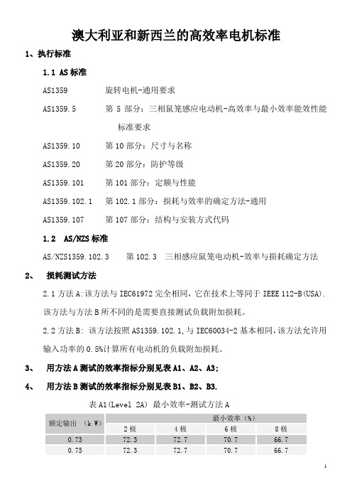
澳大利亚和新西兰的高效率电机标准1、执行标准1.1 AS标准AS1359 旋转电机-通用要求AS1359.5 第5部分:三相鼠笼感应电动机-高效率与最小效率能效性能标准要求AS1359.10 第10部分:尺寸与名称AS1359.20 第20部分:防护等级AS1359.101 第101部分:定额与性能AS1359.102.1 第102.1部分:损耗与效率的确定方法-通用AS1359.107 第107部分:结构与安装方式代码1.2AS/NZS标准AS/NZS1359.102.3 第102.3 三相感应鼠笼电动机-效率与损耗确定方法2、损耗测试方法2.1方法A:该方法与IEC61972完全相同,它在技术上等同于IEEE 112-B(USA).该方法与方法B所不同的是需要直接测试负载附加损耗。
2.2方法B: 该方法按照AS1359.102.1,与IEC60034-2基本相同,该方法允许用输入功率的0.5%计算所有电动机的负载附加损耗。
3、用方法A测试的效率指标分别见表A1、A2、A3;4、用方法B测试的效率指标分别见表B1、B2、B3.表A1(Level 2A) 最小效率-测试方法A额定输出(k W)最小效率(%)2极4极6极8极0.73 72.3 72.7 70.7 66.7 0.75 72.3 72.7 70.7 66.73 81.2 81.2 79.9 78.24 82.8 82.8 81.6 80.15.5 84.4 84.4 83.3 82.07.5 85.8 85.8 84.7 83.711 87.2 87.2 86.4 85.615 88.3 88.3 87.7 87.118.5 89.0 89.0 88.6 88.022 89.5 89.5 89.1 88.730 90.5 90.5 90.2 89.937 91.1 91.1 90.8 90.645 91.7 91.7 91.5 91.255 92.2 92.2 92.0 91.875 92.9 92.9 92.8 92.790 93.4 93.2 93.2 93.0110 93.8 93.8 93.7 93.5132 94.2 94.1 94.1 93.8150 94.5 94.5 94.4 94.1﹤185 94.5 94.5 94.4 94.1注:1. 澳大利亚与10月1日至2006年3月31日实行.新西兰从2002年7月1日起实施.表A2 (Level 1A) 最小或(高)效率—测试方法A额定输出(k W)最小或(高)效率(%)2极4极6极8极0.73 78.8 80.5 76.0 71.80.75 78.8 80.5 76.0 71.81.1 80.6 82.2 78.3 74.71.5 82.6 83.5 79.9 76.82.2 84.1 84.9 81.9 79.43 85.3 86.0 83.5 81.34 86.3 87.0 84.7 82.85.5 87.2 87.9 86.1 84.57.5 88.3 88.9 87.3 86.0 11 89.5 89.9 88.7 87.7 15 90.3 90.8 89.6 88.9 18.5 90.8 91.2 90.3 89.7 22 91.2 91.6 90.8 90.255 93.2 93.5 93.1 92.975 93.9 94.0 93.7 93.790 94.2 94.4 94.2 94.1110 94.5 94.7 94.5 94.5132 94.8 94.9 94.8 94.8150 95.0 95.2 95.1 95.2﹤185 95.0 95.2 95.1 95.2 注: 1. 最小效率在澳大利亚从2006年4月1日起实施.表A3(Heff-A) 最小高效效率—测试方法A额定输出(k W)最小高效效率 %2极4极6极8极0.73 81.4 82.9 78.8 75.00.75 81.4 82.9 78.8 75.01.1 83.0 84.5 80.9 77.61.5 84.8 85.6 82.4 79.62.2 86.2 86.9 84.2 81.93 87.2 87.8 85.6 83.64 88.1 88.7 86.7 85.05.5 88.9 89.5 87.9 86.57.5 89.9 90.4 89.0 87.811 90.9 91.3 90.2 89.315 91.6 92.1 91.0 90.418.5 92.1 92.4 91.6 91.122 92.4 92.8 92.1 91.530 93.1 93.4 92.8 92.437 93.6 93.8 93.3 92.945 93.9 94.1 93.7 93.555 94.2 94.4 94.1 93.975 94.8 94.9 94.6 94.690 95.0 95.2 95.0 94.9110 95.3 95.5 95.3 95.3132 95.5 95.6 95.5 95.5150 95.7 95.9 95.8 95.9 ﹤185 95.7 95.9 95.8 95.9 注:澳大利亚从2006年4月1日起实施。
- 1、下载文档前请自行甄别文档内容的完整性,平台不提供额外的编辑、内容补充、找答案等附加服务。
- 2、"仅部分预览"的文档,不可在线预览部分如存在完整性等问题,可反馈申请退款(可完整预览的文档不适用该条件!)。
- 3、如文档侵犯您的权益,请联系客服反馈,我们会尽快为您处理(人工客服工作时间:9:00-18:30)。
AS/NZS 1735.18:2002澳大利亚/新西兰标准电梯,自动扶梯和自动人行道第18节:自动控制的私人住宅用乘客电梯前言这个标准是由澳大利亚标准和新西兰标准委员会ME-004共同制定的,电梯安装,用来替代标准AS1735.16-1993,即是:电梯、自动扶梯和自动人行道,第16节:采用自动控制的带限制功能的乘客电梯。
制定这个标准的目的是为在私人住宅区安装小型、低速乘客电梯提供帮助。
标准中使用了“提供信息的”这个单词,主要是用来定义所采用的附录的应用场合。
一个“提供信息的”附录只是用来提供信息或者参考。
内容第一节总章1.1 范围 (6)1.2 参考文献 (6)1.3 定义 (7)第二节设计限制2.1 速度 (8)2.2 行程 (8)2.3 额定负载 (8)2.4 轿箱尺寸 (8)2.5 安全因子 (8)第三节材料3.1 概要 (9)3.2 耐久性 (9)第四节驱动机械4.1 概要 (10)4.2 轴及其附属部分 (10)4.3 驱动方向 (10)4.4 手动操作 (10)4.5 设备固定 (10)第五节悬挂及其支撑系统5.1 方式 (12)5.2 钢索 (12)5.3 链条 (15)5.4 齿轮齿条 (15)5.5 螺杆驱动 (15)5.6 液压 (16)第六节井道6.1 支撑结构 (17)6.2 井道封装 (17)6.3 井道表面 (17)6.4 轿箱顶部超行程 (18)6.5 轿箱间隙 (18)6.6 地坑不能超过建筑最底层 (20)第七节导轨7.1 规定 (22)7.2 长度 (22)7.3 导轨及其固定物 (22)7.4 导轨偏移 (22)第八节导轨器8.1 概要 (23)8.2 滚子导轨器 (23)第九节缓冲器9.1 底部缓冲器 (24)9.1 顶部缓冲器 (24)第十节安全钳10.1 规定 (25)10.2 材料 (25)10.3 结构 (25)10.4 执行器 (25)10.5 释放 (25)10.6 性能 (25)第十一节配重块11.1 概要 (26)11.2 防护 (26)第十二节轿箱12.1 框架 (27)12.2 封装 (27)12.3 入口数量 (27)12.4 轿箱入口安全保护 (27)12.5 高度 (28)12.6 轿箱顶 (28)12.7 通风 (28)12.8 抢救手段 (28)12.9 轿箱底防护 (29)第十三节轿厢门13.1 层站门规定 (30)13.2 类型 (30)13.3 宽度 (30)13.4 高度 (30)13.5 建造 (30)13.6 开门力 (30)13.7 层站门自锁 (30)13.8 门铰链上光 (31)第十四节门锁和门开关14.1 轿箱 (32)14.2 停层 (32)第十五节控制装置15.1 位置 (34)15.2 操作控制按钮 (34)15.3 可逆型接触器 (34)15.4 操作回路 (34)15.5 防爬调平装置 (35)15.6 轿箱入口阻碍物传感器控制器 (35)第十六节电气16.1 电源 (36)16.2 配线 (36)16.3 回路制动器或开关 (36)16.4 门锁回路 (37)16.5 电机防护 (37)16.6 停层开关 (37)16.7 限位开关 (38)16.8 反相继电器 (38)16.9 安全钳开关 (38)16.10钢索或链条开关 (38)16.11井道挡板开关 (38)16.12安全阀测试电闸 (39)16.13地坑停层开关 (39)16.14滑轮或平台停止开关 (39)16.15闭锁装置开关 (39)16.16支撑螺母安全开关 (39)第十七节照明17.1 常用照明 (40)17.2 紧急照明 (40)17.3 地坑和顶部照明 (40)17.4 控制设备照明 (40)第十八节通讯18.1 规定 (41)18.2 可到达性 (41)18.3 电话系统 (41)18.4 声音报警 (41)第十九节公告19.1 载重牌 (42)19.2 标示牌 (42)19.3 紧急指示 (42)附录A 维修保养 (43)B 电梯类型选择指南 (44)澳大利亚/新西兰标准电梯,自动扶梯和自动人行道第18节:自动控制的私人住宅用乘客电梯第一节总章1.1 范围这个标准是特别为安装在私人住宅区的自动控制的小型低速乘客电梯制定的,定义在标准AS 1735.1中。
这个标准是对AS 1735.1的补充,但是这个标准的要求要优于相关标准的要求。
注意事项:1 维修保养指南在附录A中。
2电梯类型选择指南在附录B中。
1.2 参考文献这个标准参考了下列文献:AS1023低压开关设备和控制装置-保护电机1023.1 第一部分:建立热探测器和相关控制单元1023.3 第三部分:继承过热保护。
1532 滚子链和链轮的短节距精确传递1735 电梯,自动扶梯和自动人行道1735.1 第一部分:总章1735.2 第二部分:乘客和电气电梯1735.3 第三部分:乘客和液压电梯1735.10 第十部分:检测1831 铸铁-球铁或蠕墨铸铁1979 电缆-电梯-软传递3569 钢索AS/NZS3000 电气安装(见澳大利亚/新西兰配电标准)3013 电气安装(配电系统防火和机械安装等级)ISO4347 板式链,马蹄铁,槽轮BS3790 锲形带传动和V带传动说明NZS4332非家用电梯1.3 定义对这个标准的目的来说,其定义在AS 1735.1中。
第二节设计限制2.1 速度轿箱速度不能大于0.3m/s。
2.2 行程轿箱行程不能大于12m。
2.3 额定负载额定负载不能小于200Kg/m2,最小不能少于115 Kg。
2.4 轿箱尺寸2.4.1 面积轿箱地板的有效面积,根据第12.4款所测不能大于1.6m2。
对于和轿箱配合的门来说,所测量的地板面积必须和AS 1735.2中的第22节相符合。
2.4.2 尺寸轿箱地板的尺寸不能小于600 mmX600 mm。
2.5 安全因子2.5.1 除驱动机械外除驱动机械外,对设备的每一处,包括任何支撑结构,在额定负载下的,基于最大压力的安全因子不能小于下面所要求的:(a)结构件,轿箱框架、安全钳 (5)(b)钢索及其附属件(ⅰ)滑轮和钢索速比≥30:1......................................................7.6 (ⅱ)滑轮和钢索速比≤20:1 ﹤30:1 (10)(c)链条及其附属件 (10)(d)铸铁 (10)(e)轿箱地板或顶部用木材 (10)2.5.2 对于驱动机械驱动机械的安全因子必须和AS 1735.2中机械的安全因子要求相符合。
第三节材料3.1 概要材料必须和AS 1735.1中所给的材料相关要求相符合。
3.2 耐久性任何暴露在外面的材料或者设备都必须是能耐风蚀。
金属制品必须能尽量减少腐蚀,木材必须能防止腐烂。
第四节驱动机械4.1 概要驱动机械必须和AS 1735.2中机械的要求相符合,它涵盖了传递扭矩的螺栓,柱头螺栓螺纹,螺杆,轴,齿轮,轴承和刹车片;另外,当刹车片集成在电梯电机中时,单个盘形刹车片或锥形刹车片也是可以的。
4.2 井筒及其附属部分如果不是在驱动单元中形成一个轴的整体部分,每个滑轮,钢索,正齿轮,螺杆,螺杆齿轮和刹车鼓都需主动轴向安装在轴上。
扭矩传递给轴或其他驱动单元可通过以下一种或多种方法:(a)沉孔键。
(b)花键。
(c)通过螺栓法兰固定在机械上行程轴或驱动单元的一个整体。
(d)螺纹销键4.3 驱动方向不是液压驱动的电梯在双向都需电驱动。
4.4 手动操作必须提供下面一种手段使得授权人能够以不超过0.15m/s的速度移动轿箱,这种情况在紧急情况下是必须的:(a)对液压电梯,所需手段在标准AS 1735.3中。
(b)一个光滑的无辐轮操纵手动缠绕单元。
(c)一个缠绕手柄,在下列情况下可打断控制回路:(ⅰ)通过在机械上安装缠绕设备。
(ⅱ)去除机械上一些设备使得缠绕设备可以安装。
(d)采用电气手段移动满载电梯停层,无需主电源或其它额外设备。
这包括从安全钳上顶起满载电梯。
(e)对于任何手动释放刹车而无需进行调整的情况,必须保证当人工施加到机械上的压力释放时,刹车片能立刻重新应用。
留在锁定位置的触发器和其它设备不能阻碍刹车片。
4.5 设备固定除了齿轮齿条或螺杆传动以及必须安装好来有效执行其功用的设备外,电梯的驱动机械、控制机构以及其它设备都需安装在一个固定区域。
这个区域不能包含其它跟电梯无关的设备。
维修保养改设备的空间必须空出,拯救电梯受困人员,无需拯救人员直接进入井筒。
当在控制设备中工作时,观察电梯运动或者与电梯轿箱进行通讯必须提供给授权人员。
注:齿轮齿条传动也可安装在轿箱上或者轿箱里。
第五节悬挂及其支撑系统5.1 方式轿箱必须以其中一种方式-(a)通过钢索、不锈钢钢滚子链、不锈钢板式链悬挂。
(b)借助于螺栓、齿轮、直接液压或者间接液压驱动支撑。
5.2 钢索5.2.1 数量悬挂轿箱的钢索数量不能少于2根。
5.2.2 类型和直径选用的钢索必须遵照标准AS 3569,其名义直径不能小于6mm。
5.2.3 末端附属装置通过附属装置,悬挂的钢索在每个末端都能中止。
除了那些在装置里面的钢索,这个附属装置使得钢索的各个部分都可见。
附属装置必须是下列类型,详细见AS 1735.2(a)拼接的金属环。
(b)单个梯形状巴比特钢索环。
(c)锲形环,除了那些承受负载的钢索不需要进入标准AS 1735.2要求的直线。
(d)陷型的配合。
5.2.4 变换(如滑车索具或绳索的)位置角钢索和垂直于滑轮或轮毂轴的平面之间的角度不能大于50。
5.2.5 平衡装置必须提供一种保持悬挂钢索张力的平衡手段。
螺旋形或栅形的平衡装置被用来保证单个的机械失效不会使轿箱或任何配重变得整体分离。
5.2.6 卷筒和滑轮任何卷筒或者槽轮必须符合下列相关要求:(a)材料所选材料必须遵照以下规定:(ⅰ)牵引轮必须是钢或者铸铁的,其上要设计成带有机械沟槽,用来减少槽轮和钢索的磨损。
(ⅱ)卷筒必须是钢、铸铁或者高强度铝合金的,并带有机械沟槽。
(ⅲ)除了牵引滑轮外,滑轮的带强度和磨损性能材料至少要和遵照AS 1831标准的铸铁相等。
(b)直径轮毂和滑轮的直径和相应钢索的名义直径之比,要与2.5.1(b)(ⅰ)或2.5.1(b)(ⅱ)相符合。
(c)钢索沟槽除了单个缠绕式驱动滑轮外,钢索沟槽表面的截面积必须:(ⅰ)圆弧不能小于悬挂钢索名义半径的105%,但是又不能大于悬挂钢索名义半径的107.5%。
(ⅱ)延伸不能小于钢索周长的1/3。
滑轮中,钢索沟槽一侧的张角大约是500。
(d)法兰轮毂和滑轮必须有延伸法兰(ⅰ)没有提供紧密结合时,超过钢索作用到轮毂或槽轮中心时,不能小于一个钢索直径。