honeywell+PRO22R2 Instal
HoneywellAccessControl(HAS)门禁系统精选产品参数手册

HoneywellAccessControl(HAS)门禁系统精选产品参数手册霍尼韦尔门禁产品精选手册原北方电脑系列1门禁管理软件系统............................................................. ....................................................41.1WinPak2 005............................................................ ......................................................41.2WinPa kPro2005....................................................... .. (6)2门禁控制器............................................................. . (10)2.1.1主控制模块(PRO22IC).................................................... ....................................102.1.2PRO22双读卡器模块(PRO22R2).................................................... ...................122.1.3PRO2200单读卡器模块(PRO22R1).................................................... ...............142.1.4PRO2200继电器输出模块(PRO22OUT)................................................... .........152.1.5PRO2200报警输入模块(PRO22IN).................................................... ................162.1.6PRO2200RS232/485通信协议转换器(PRO22CVT1).........................................172.1.7PRO2 200以太网通讯卡(PRO22EN)...................................................... .. (17)2.2NS2+两门门禁控制器............................................................. (183)Honeywell门禁系统系列前端配件............................................................. .........................193.1感应智能卡读卡器(OmniCla系列)........................................................... ..............193.2感应智能卡读卡器(JT-MCR系列)........................................................... ..................223.3ID感应读卡器(OmniPro某系列)........................................................... (234)附录............................................................. ............................................................... .........244.2主要设备、器材的选择和配置原则............................................................. . (24)4.1.1主控模块的配置............................................................. .....................................244.1.2读卡器模块的配置............................................................. ..................................244.1.3读卡器的配置............................................................. ........................................254.1.4电锁的配置............................................................. ............................................254.2系统调试............................................................. . (25)4.2.1系统阻抗测试.....................................................................................................264.2.2阻抗测量............................................................. ................................................264.2.3绝缘阻抗测量............................................................. .........................................264.2.4系统接地电阻测量............................................................. ...............................264.2.5各种模块(主控模块及扩展模块等)通电调试..................................................264.2.6前端设备调试............................................................. .......................................274.2.7系统联调............................................................. ..............................................274.2.8系统试运行。
安全防范系统介绍1

38
安防相关规范
验收规范 智能建筑工程质量验收规范GB50339-2003 智能建筑工程质量验收规范 安全防范系统验收规则GA308-2001 安全防范系统验收规则
ห้องสมุดไป่ตู้39
安全防范系统验收
40
谢谢
41
安防系统技术与规范
2011.09
1
目录
安防系统概述 安防各子系统介绍 安防系统相关国家规范
2
什么是安全防范系统
安全防范系统(SPS) security & protection system 以维护社会公共安全为目的,运用安全防 范产品和其它相关产品所构成的入侵报警系统、视 频安防监控系统、出入口控制系统、防爆安全检查 系统等;或由这些系统为子系统组合或集成的电子 系统或网络。
28
4.巡更管理系统
29
4.1巡更管理系统定义
一种通过先进的移动自动识别技术, 一种通过先进的移动自动识别技术,将巡逻人员在 巡更巡检工作中的时间, 巡更巡检工作中的时间,地点及情况自动准确记录下 是治安管理中人防与技防一种有效的, 来。是治安管理中人防与技防一种有效的,科学的整 合管理方案。 合管理方案。
32
4.4巡更管理拓扑图
33
4.4巡更管理系统
巡更管理知名品牌 北京蓝卡 北京兰德华
34
5.停车场管理系统
35
5.停车场管理系统
停车场管理系统分为3个部分 停车场管理系统分为 个部分 入口设备:栏杆机(或叫道闸),车辆检测器, ),车辆检测器 一、入口设备:栏杆机(或叫道闸),车辆检测器, 入口验票机(或读卡器读卡机),入口摄像机, ),入口摄像机 入口验票机(或读卡器读卡机),入口摄像机,剩余 车位显示屏等其他选配 出口设备:栏杆机(或叫道闸),车辆检测器, ),车辆检测器 二、出口设备:栏杆机(或叫道闸),车辆检测器, 出口验票机(或读卡器读卡机),出口摄像机, ),出口摄像机 出口验票机(或读卡器读卡机),出口摄像机,等其 他选配 管理中心设备:管理服务器,发卡器, 三、管理中心设备:管理服务器,发卡器,临时卡计 费器等
Honeywell TR21、TR22、TR23、TR24 壁模块说明书
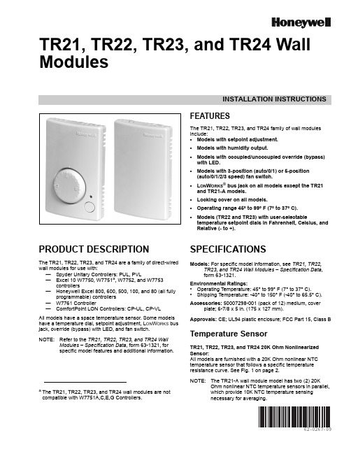
INSTALLATION INSTRUCTIONS62-0267-09TR21, TR22, TR23, and TR24 Wall ModulesFEATURESThe TR21, TR22, TR23, and TR24 family of wall modules include:•Models with setpoint adjustment.•Models with humidity output.•Models with occupied/unoccupied override (bypass) with LED.•Models with 3-position (auto/0/1) or 5-position (auto/0/1/2/3 speed) fan switch.•L ON W ORKS ® bus jack on all models except the TR21 and TR21-A models.•Locking cover on all models.•Operating range 45° to 99° F (7° to 37° C).•Models (TR22 and TR23) with user-selectabletemperature setpoint dials in Fahrenheit, Celsius, and Relative (- to +).PRODUCT DESCRIPTIONThe TR21, TR22, TR23, and TR24 are a family of direct-wired wall modules for use with:—Spyder Unitary Controllers: PUL, PVL—Excel 10 W7750, W7751a , W7752, and W7753controllers—Honeywell Excel 800, 600, 500, 100, and 80 (all fullyprogrammable) controllers —W7761 Controller—ComfortPoint LON Controllers: CP-UL, CP-VL All models have a space temperature sensor. Some models have a temperature dial, setpoint adjustment, L ON W ORKS bus jack, override (bypass) with LED, and fan switch.NOTE:Refer to the TR21, TR22, TR23, and TR24 WallModules – Specification Data , form 63-1321, for specific model features and additional information.SPECIFICATIONSModels: For specific model information, see TR21, TR22,TR23, and TR24 Wall Modules – Specification Data , form 63-1321.Environmental Ratings:•Operating Temperature: 45° to 99° F (7° to 37° C).•Shipping Temperature: -40° to 150° F (-40° to 65.5° C).Accessories: 50007298-001 (pack of 12) medium, coverplate; 6-7/8 x 5in. (175 x 127 mm).Approvals: CE; UL94 plastic enclosure; FCC Part 15, Class BTemperature SensorTR21, TR22, TR23, and TR24 20K Ohm Nonlinearized Sensor:All models are furnished with a 20K Ohm nonlinear NTC temperature sensor that follows a specific temperature resistance curve. See Fig. 1 on page 2.NOTE:The TR21-A wall module model has two (2) 20KOhm nonlinear NTC temperature sensors in parallel, which provide 10K NTC temperature sensingnecessary for averaging.a The TR21, TR22, TR23, and TR24 wall modules are notcompatible with W7751A,C,E,G Controllers.TR21, TR22, TR23, AND TR24 WALL MODULES62-0267—092Fig. 1. Temperature vs. Resistance for Nonlinear Sensor.CommunicationsAll wall modules (except the TR21 and TR21-A models) havea L ON M ARK ® bus communications port. If needed, the jack plug must be removed in the field, and terminals 3 and 4 wired according to the installation instructions.The recommended wire size for the L ON M ARK ® bus is Level IV, 22 AWG (0.34 sq.mm) plenum or non-plenum rated, non-shielded, twisted pair, solid conductor wire.Fig. 2. Wall Module Features (TR23-F Shown).BEFORE INSTALLATIONFailure to follow proper wiring practices canintroduce disruptive electrical interference (noise).Keep wiring at least one foot away from large inductive loads such as motors, line starters, lighting ballasts, and large power distribution panels.Shielded cable is required in installations where these guidelines cannot be met.Ground shild only to grounded controller case.IMPORTANTAll wiring must comply with local electrical codes and ordinances or as specified on installation wiring diagrams.—Wall module wiring can be sized from 16 to 22 AWG (1.31 to 0.33 sq. mm) depending on the application.—The maximum length of wire from a device to a wall module is 1000 ft. (305 m).—Twisted pair wire is recommended for wire runs longer than 100 ft. (30.5 m).INSTALLATIONMount the wall module on an inside wall approximately 54 in. (1372 mm) from the floor (or in the specified location) to allow exposure to the average zone temperature. Do not mount the wall module on an outside wall, on a wall containing water pipes, or near air ducts. Avoid locations that are exposed to discharge air from registers or radiation from lights,appliances, or the sun. See “Cover Disassembly” on page 3.The wall module can be mounted on a wall, on a standard utility conduit box using No. 6 (3.5 mm) screws or on a 60mm wall outlet box (see Fig.3). When mounting directly on a wall, use the type of screws appropriate for the wall material.Fig. 3. Mounting on Standard Utility Conduit Box or60 mm Wall Outlet Box (TR23 Shown).FRONT COVERTR21, TR22, TR23, AND TR24 WALL MODULES362-0267—10Fig. 4. Wall Module Subbase Dimensions in Inches (mm) and Temperature Limit Set Screw Locations (TR23Shown).Cover DisassemblyA snap-fit locking mechanism is used to attach the cover of the wall module to its subbase. To disassemble the cover from the subbase:1.Insert a thin, flat blade screwdriver into each of the twoslots at the bottom of the module to release the two locking tabs. See Fig.2 on page 2.2.Tilt the cover out and away from the subbase to releasethe top two locking tabs.3.To change the dial (e.g. from Fahrenheit to Celsius)release the two tabs on the inside of the front cover and remove the old dial.WiringAttach the wires from the device sensor terminals to the appropriate wall module terminals. See Table 1 on page4.Screw type terminal blocks are designed to accept no more than one 16 AWG (1.31 sq. mm) conductor.Connect multiple wires that are 16-18 AWG(1.31-0.82 sq. mm) with a wire nut. Include a pigtail with this wire group and attach the pigtail to the individual terminal block.Wiring Wall ModulesWire the terminal block as follows:1.For single wires, strip 3/16 in. (5 mm); for multiple wiresgoing into one terminal, strip 1/2 in. (13 mm) insulation from the conductor.2.If two or more wires (20 to 22 AWG only) are beinginserted into one terminal, twist the wires together before inserting. See Fig. 5.3.Insert the wire in the required terminal location and tighten the screw to complete the termination.4.Review and verify the terminal connection wiring and DIP switch settings illustrated in Table 1 on page 4.NOTE:Wire the Lon connection (terminals 3 and 4) usingLevel IV 22 AWG (0.34 mm 2) plenum or non-plenum rated, unshielded, twisted pair, solid conductor wire.Wiring ExamplesTable 1 on page 4 illustrates DIP switch settings and terminal connections for the wall modules. Refer to the TR21, TR22, TR23, and TR24 Wall Modules – Specification Data , form 63-1321, for additional DIP Switch information.IMPORTANTSW 2 on DIP Switch S2 is used for factory calibration of the temperature setpoint potentiometer.Depending on calibration, this switch may be set in either the On or Off position.DO NOT change the position of this switch.NOTES:1.The TR21 and TR22 models do not use DIP Switch S1 and S3.2.DIP Switch S1 is used only on the humidity models, TR21-H and TR23-H.3.Models TR21 and TR21-A use terminals 1 and 2 only. Model TR21-J uses terminals 1, 2, 3, and 4 only.Fig. 5. Attaching Two Wires (20 to 22 AWG) to Wall ModuleTerminals.Attaching the CoverWhen all wiring is complete, attach the cover of the Wall Module as follows:1.Optional : For models with a temperature dial, insert thetwo setpoint screws into the inside of the cover to set the desired temperature range limit. See Fig.4.2.Press the cover straight down onto the subbase until itsnaps into place.3.For models with a temperature dial, insert the desireddial through the opening in the cover. Align the keyed shaft on the knob with the keyed slot into the fitting on the subbase, then press down until it snaps into place.TR21, TR22, TR23, AND TR24 WALL MODULESWiring and DIP switch settings:See Table 1 to determine DIP switch positions and terminal usage for each controller.Table 1. DIP Switch Settings and Terminal Connections.62-0267—094TR21, TR22, TR23, AND TR24 WALL MODULES562-0267—09TR22 and TR23 Setpoint AdjustmentFor the TR22 and TR23 Wall Modules with a setpointadjustment, the controller must be programmed for the values in Table 2 and Table 3.TR23-KL and TR23-H-KLThe TR23-KL and TR23-H-KL ship in packs of 20 and are supplied without setpoint adjustment knobs. Knobs can be ordered separately. See Table 4 for Knob model numbers.Humidity Settings (DIP switch S1)The humidity sensing control mode is set with this 2-position DIP switch. Refer to Fig.4 on page 3 for location of DIP switch S1.NOTE:These switch settings apply only to the TR21-H andTR23-H models.To change the setting, first disconnect the power, then set SW1 and SW2 according to Table 5.TR23 and TR24 Wall Module Override (Bypass) Pushbutton and LED OperationWhen Used With Excel 10 Controllers:The Excel 10 controllers (W7750, W7751, W7752, andW7753) provide timed occupied and unoccupied temperature setpoints for the Wall Module, see Fig. 6. The override pushbutton is used to change the controller into the modes shown in Table 6 and illustrated in Fig.7 on page 6. The override (bypass) LED displays the override status of the controller.Fig. 6. LED and override pushbutton locations(TR23-F Wall Module shown).Table 2. Setpoint Values.Setpoint Value Program Setting55°F (13°C) 2.773 V 65°F (18°C) 2.148 V 75°F (24°C) 1.345 V 85°F (29°C)0.43 VTable 3. Wall Module Setpoint Configuration.Model Setpoint Resistance (Ohms)°F Absolute 55°F 957485°F1426Relative -9°F offset from 70°F 9574+9°F offset from 70°F1426°C Absolute12°C 994530°C1150Table 4. Knob Model NumbersModel DescriptionKNOB-C Celsius scale knob (pack of 20)KNOB-F Fahrenheit scale knob (pack of 20)KNOB-ORelative scale knob (pack of 20)Table 5. DIP Switch S1 Settings.Wall Module Model Sensing Control Individual Switches 12TR21-H TR23-H0-10 Vdc OFF OFF 0-5 Vdc OFF ON 4-20 mAONOFFTR21, TR22, TR23, AND TR24 WALL MODULES62-0267—096Fig. 7. Override pushbutton operation.When Used With Excel 600/500/100/80/50 Controllers:The application engineer/programmer can program theoverride (bypass) and LED to operate in any manner desired. The override (bypass) input is a dry contact, normally open, momentary digital input when the wall module does not have a fan switch. When a fan speed switch (basically a series of resistances based on fan switch position) is present, the override button is an analog input. See Table 4 for resistances.When Used With T7350 Thermostat:TR21, TR21-A, TR21-H, TR22, TR23, and TR24 are the models compatible with the T7350 thermostat. When using with the T7350 thermostat be sure to use the relative +/- offset knob only. The Celsius and Fahrenheit knobs will not work properly with the T7350 Thermostat.TR22-F5, TR23-F3, and TR23-F5 Wall Module Fan SwitchWith the switch in the far left position (Auto), the fanautomatically runs at the speed determined by the controller temperature control algorithm.With the switch in the 0 position, the fan is off. Position 1 is fan speed 1, etc.The wall module fan speed switch overrides the temperature control algorithm.When Used With Excel 10 Controllers:The Excel 10 Controllers (W7750, W7751, W7752, andW7753) can be programmed so that the fan speed switch and override button function the way that the application engineer/programmer wants. See Table 7 for controller-programming resistances. Switch 1 on Dip Switch S2 adds 10k Ohms resistance when OPEN (for Excel 600-80 controllers) and removes it when CLOSED (for Excel 10 controllers).When Used With Excel 600/500/100/80/50 Controllers:Excel 600/500/100/80 Controllers can be programmed so that the fan speed switch and override button function the way that the application engineer/programmer wants. See Table 8 for controller-programming resistances. Switch 1 on Dip Switch S2 adds 10k Ohms resistance when OPEN (for Excel 600-80 controllers) and removes it when CLOSED (for Excel 10 controllers).Table 6. Wall Module Operation.Pushbutton Held Down Controller Model LED Status0 to 1 second No override Off 1 to 4 seconds Timed occupied override On4 to 7 seconds Unoccupied override Single blink per secondLonger than 7 seconds No overrideOffnot applicableContinuous occupied override aaRemote function, which is generated from the network.Two blinks per secondTable 7. Program Settings for Wall Modules withFan Switch using Excel 10 Controllers.For Switch Position Resistance (Ohms)Comment Auto 1861 ±119Left most position 02686 ±127Fan Off position13866 ±13923041 ±13034601 ±146Right most positionOverride button closed Closed circuitTable 8. Program Settings for Wall Modules with Fan Switch using Excel 600/500/100/80 Controllers.For Switch Position Resistance (Ohms)Comment Auto 11.861K ±119Left most position 012.686K ±127Fan Off position113.866K ±139213.04K ±130314.60K ±146Right most positionOverride button closed 10K ±100TR21, TR22, TR23, AND TR24 WALL MODULES 762-0267—09TR21, TR22, TR23, AND TR24 WALL MODULESAutomation and Control Solutions Honeywell International Inc.Honeywell Limited-Honeywell Limitée 1985 Douglas Drive North 35 Dynamic DriveGolden Valley, MN 55422Toronto, Ontario M1V 4Z9® U.S. Registered Trademark© 2009 Honeywell International Inc.62-0267—09E.K. Rev. 09-09L ON W ORKS ® is a registered trademark of Echelon ® Corporation.L ON M ARK ® and the LonMark Logo are trademarks of the LonMark Association.By using this Honeywell literature, you agree that Honeywell will have no liability for any damages arising out of your use or modification to, the literature. You will defend and indemnify Honeywell, its affiliates and subsidiaries, from and against any liability, cost, or damages, including attorneys’ fees, arising out of, or resulting from, any modification to the literature by you.。
Honeywell_传感器_技术参数 2
目录:水系统传感器 (2)水流开关WFS-1001-H (2)液位开关MAC-3-5M (2)水管式压差传感器P7620C (3)水管式压力传感器P7620A (4)流量变送器8550+2517 (5)VF20T浸入式温度传感器 (5)风系统传感器 (7)DPS系列气流压差开关 (7)DPTM系列压差变送器 (7)风管式温度传感器LF20 (8)风管式温度传感器LF20-C (9)室外温度传感器T7416A1022 (9)室内温度传感器T7412A1000 (9)室内温度传感器CTR21 (10)风管式温湿度传感器H7050B1018 (10)风管式温湿度变送器H7050B1117 (11)室内温湿度变送器H7030A1000 (12)室内温湿度传感变送器H7012B1023 (12)室内温湿度传感器CTR21-H (13)风管式温湿度传感器H7015B1020 (14)室外温湿度传感变送器H7508A1042 (14)CDS2000 系列二氧化碳传感器 (15)C7110C1001(替换已停产的AQS51) 系列二氧化碳传感器 (15)AQS71-KAM(替换已停产的AQS51-KAM) 系列二氧化碳传感器 (16)GD250W3E 系列一氧化碳传感器 (17)C7110A1005系列房间空气质量传感器 (17)L4064K1006B 高温断路开关,手动复位 (18)T6950A1000 低温短路开关,手动复位 (18)数字化挂墙模块T7560 温度传感器 (19)数字化挂墙模块T7460 温度传感器 (19)水系统传感器水流开关 WFS-1001-H应用∙ WFS 水流开关具有SPDT 输出,性能优异,高精度可靠性,可安装在水管和对铜无腐蚀性液体中,当液体流量达到整定速率时,可不到整定点,其一个回路关闭,另一个回路打开,典型应用于连锁作用或断流保护的场所。
∙ WFS 系列开关仅用0℃以上液体介质,它亦可于高盐或氯气的液体,但是非易燃介质。
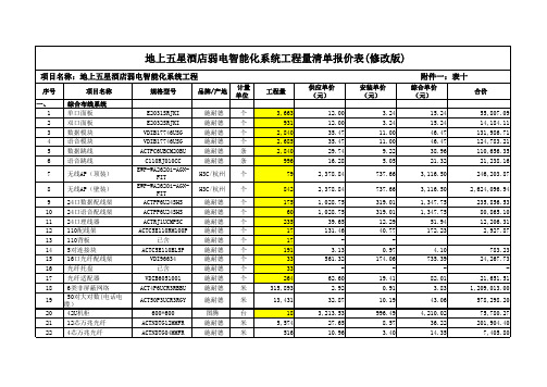
弱电智能化系统清单报价

一、 1 2 3 4 5 6
7
项目名称
综合布线系统 单口面板 双口面板 数据模块 语音模块 数据跳线 语音跳线
无线AP(顶装)
8
无线AP(壁装)
9
24口数据配线架
10 24口语音配线架
11 24口理线器
12 110配线架
13 110背板
14 5对连接块
15 16口光纤配线架
16 光纤托盘
17 光纤适配器
ACTC5E110RM100P
施耐德
个
已含
施耐德 个
ACTC5E110BL5P
施耐德 个
VDI96634
施耐德 个
已含
施耐德 个
VDIB6051001
施耐德 个
ACT4P6UCR3RBBU
施耐德 米
ACT50P3UCR3RGY
施耐德 米
600*600 ACTNDTG12MMFR ACTNDTG04MMFR ACTFP2L3M35M20
0.97 174.06
19.41
0.91
10.19
996.49 8.57 3.40
16.35
综合单价 (元)
15.24 15.24 46.47 46.47 38.96 21.32
3,116.50
3,116.50
1,347.75 1,347.75
51.94 172.23
4.10 735.39
82.01
494.22 494.22 164.74
3.21
878.61 2,086.71
109.83 604.05
54.91 54.91 768.79 878.61 4,942.20
-
3.41
超五星酒店弱电系统清单(含报价)
79
842
175 60
235 17 17
191 33 33
264 315,893
13,431
18 5,574
516
供应单价 (元)
12.00 12.00 35.47 35.47 29.74 16.28
2,378.84
2,378.84
1,028.75 1,028.75
39.65 131.46
3.13 561.32
附件一:表十
综合单价 (元)
合价
15.24 15.24 46.47 46.47 38.96 21.32
3,116.50
3,116.50
1,347.75 1,347.75
51.94 172.23
55,807.09 14,184.11 131,986.71 124,783.21 110,656.35 21,238.16
DS-VSDS2MPX18PO
tyco
台
2
室内网络一体机高速 球(含支架)
DS-VSDS2MPX18PI
tyco
台
3
半球网络摄像机低照 度
DS-VSDD2MPTWVF39HIRI
tyco
台
4
电梯摄像机
DS-VSSD550FF36B
tyco
台
5
楼层显示器
DT-7014
国产优质 台
400
52.72
2
20,867.06
1
4,447.98
1,379.28
5,827.26
6,073.30 102,194.59
5,990.42 5,827.26
5
6
7
8 9 10 11 12 13
Honeywell SCBA (自主式氧气保障装置) 3L 200bar 紧急氧气设备说明书

France PartenairesOù acheterIndustries chimiques Pétro-chimieNuméro de référence1815732Type de produitProtection respiratoireGammeSCBA (Appareil de protection respiratoire autonome)LigneSystèmes de filtration à air compriméMarqueHoneywellMarque anciennement connue sous le nom deSPERIANIndustriePrésentation généraleCaractéristiqueSifflet d’alarme puissant de fin d’autonomie en matière composite, positionné près de l’oreilles et qui ne consomme pas d’air (air réinjecté dans la cagoule).AvantageSécurité accrueCaractéristiqueCoussin gonflable.Caractéristiques & AvantagesBio-S-Cape avec bouteilled’air 3L / 200 bar , Acier, 15minutesCODE ARTICLE: 1815732Le Bio-S-Cape est un appareil respiratoire d’évacuationd’urgence à air comprimé conçu pour offrir une grandefacilité de mise en place, combinée à uneprotection respiratoire optimale. Il est contenu dans unsac de transport dont l’ouverture déclencheautomatiquement l’apport en air respirable contenu dansla bouteille. Une légère surpression dans la cagouleévite tout risque d’inhalation de gaz toxiques. Le réglagede la cagoule est automatique grâce au coussin d’airgonflable intégré au niveau de la nuque. Ce systèmepermet une bonne stabilisation de la cagoule sur la tête,offre un meilleur confort respiratoire et laisse les mainslibres pendant l’installation, garantissant un niveau desécurité maximal. Un sifflet d’alarme situé prêt de l’oreilleindique lorsque la réserve d’air est sur le point d’êtreterminée.Sécurité accrueCaractéristiqueLe flexible de la cagoule est à l’arrière sur le côté de la cagoule.AvantageSécurité accrueCaractéristiqueFlexible anti-pincement.AvantageSécurité accrueCaractéristiqueRevêtement intérieur noir de la cagouleAvantageSécurité accrueCaractéristiqueSystème anti-déchirure sur le joint de cou.AvantageSécurité accrueCaractéristiqueSystème d’évacuation des liquides dans le sac.AvantageSécurité accrueCaractéristiqueEtiquette d’identification accessible par l’intérieur du sacAvantageSimplicité d'utilisationCaractéristiquePositionnement de l’étiquette dans l’axe du sacAvantageSimplicité d'utilisationCaractéristiqueSurpression maintenue dans la cagouleAvantageSécurité accrueCaractéristiqueDétendeur déclenché automatiquement dès l’ouverture du sacAvantageSécurité accrueCaractéristiqueUne cagoule avec une large visibilité qui s’adapte à tous les types de visage et d’environnements AvantageSécurité accrueCaractéristiqueUn grand choix de bouteillesAvantageConfort accruCaractéristiqueMaintenance simplifiéeAvantageSimplicité d'utilisationEBAEN 1146:2005, ISO 23269-1:2008, SOLAS, MED, IMO, MSCCagoulePVC résistant (couleur orange), ouverture rapide, bandes réfléchissantes, plombage de sécurité, grande fenêtre, Système d’évacuation des liquidesMatériau de la cagoulePolyurethaneHarnais de sac à dosPVC résistant (couleur orange), ouverture rapide, bandes réfléchissantes, plombage de sécurité, grande fenêtre, Système d’évacuation des liquidesMatériau du harnais de sac à dosPVC (orange)PneumatiqueBio-S-Cape avec bouteille d’air 3L / 200 bar , Acier, 15 minutesDétendeur Niveau 1Déclenchement automatique à l’ouverture du sac; incluant un raccord de chargement intégré ENTempérature d'utilisation nominale-15°C/+60°CMallette de transport en optionCoffret mural pour stockage Bio-S-CapeEPI catégorie EU3Assurance qualitéISO 9001 / 2000Certification EUEU AttestationCertificationsEN 1146:2005REACHConformité au règlement CE 1907/2006 (REACH)The substance(s) listed below may be contained in this product above the threshold level of 0.1% byweight of the listed article.Références des produits vendus en Europe Substance > 0,1 %Nom de la substance Numéro CASNo Substance ContentAdditional Certification LinkMED certificateManuel d'utilisationBIO-S-CAPE user manual© Honeywell International Inc.。
WEBs 应用手册说明书

WEBs 应用手册关于霍尼韦尔霍尼韦尔是一家《财富》全球500 强的高科技企业。
我们的高科技解决方案涵盖航空、汽车、楼宇、住宅和工业控制技术,特性材料,以及物联网。
我们致力于将物理世界和数字世界深度融合,利用先进的云计算、数据分析和工业物联网技术解决最为棘手的经济和社会挑战。
在中国,霍尼韦尔长期以创新来推动增长,贯彻“东方服务于东方”和“东方服务于全球”的战略。
霍尼韦尔始创于1885 年,在华历史可以追溯到1935 年,在上海开设了第一个经销机构。
目前,霍尼韦尔四大业务集团均已落户中国,上海是霍尼韦尔亚太区总部,在华员工人数约11,000 人。
同时,霍尼韦尔在中国的30 多个城市拥有50 多家独资公司和合资企业,其中包括20 多家工厂,旨在共同打造万物互联、更智能、更安全和更可持续发展的世界。
欲了解更多公司信息,请访问霍尼韦尔中国网站www. ,或关注霍尼韦尔官方微博和官方微信。
霍尼韦尔霍尼韦尔智能建筑科技集团我们在全球拥有23,000 多名员工。
我们的产品、软件和技术已在全球超过1,000 万栋建筑中使用。
我们的技术确保商业楼宇业主和用户的设施安全、节能、具有可持续性与高生产力。
霍尼韦尔智能建筑科技集团深耕中国40 多年来,参与了30 多个城市的150 多条地铁的建设,为500 多座机场的智慧和安全保驾护航,为600 多家酒店提供智能管理系统,为1000多家医院提供了数字化解决方案。
目录第一部分 (4)霍尼韦尔智慧楼宇系统架构示意图 (4)霍尼韦尔智慧能源管理解决方案 (6)WEBs N4管理软件 (9)霍尼韦尔智慧触控屏 (13)第二部分 (17)系统控制器 WEB 8000 系列 (17)系统控制器 WEB 8000 VAV 专用系列 (21)边缘数据管理器 (24)增强型可编程通用控制器 (27)可编程通用控制器 (30)可编程通用控制器扩展模块 (33)BACnet 可编程通用 / VAV 控制器 (36)Lonworks 可编程通用 / VAV 控制器 (39)VAV 控制器 (43)BACnet 通用控制器 (46)Sylk TM I/O 扩展模块 (49)MVCweb 控制器 (52)UB系列独立控制器 (55)第三部分 (59)房间温控单元 (59)变风量末端墙装模块 (63)WTS3/6 系列温控器 (65)WTS8/9 系列温控器 (69)WS9 系列墙装模块 (73)建筑网络适配器 (76)智能电表 (78)4Ethernet / LANBACnet MS/TP Modbus RTU LonworksKNXSylk BusLightingModbus TCP BACnet IPBACnet IPAlarm Console clientWEB 8000 Web ControllerWEBStation Supervisor智慧触控屏Sylk I/O ModuleLonworks Spyder边缘数据管理器Spyder Universal ControllerPUC BACnet MS/TP Controller霍尼韦尔智慧楼宇系统架构示意图系统示意图仅用于显示设备在系统中的层次关系以及支持的通讯协议具体配置细节请结合实际项目情况,联系霍尼韦尔技术工程师进行架构设计5ElectricitySubmeterBACnet IPBACnet IPHTTPs , BACnet IP , oBIX , SNMP , …WEBs Enterprise Security WEBs Energy AnalyticsHAQ61增强型 BACnet IP ControllerFCU Wall ModuleVAV Controller EM Bus I/O ModuleSylk Bus Wall Module增强型 BACnet IP ControllerEM Bus6霍尼韦尔智慧能源管理解决方案智能高效,机器自学习功能准确分析,快速发现能耗异常功能全面,基于能耗大数据采集、趋势分析、评估诊断和流程控制的闭环管理功能数据准确,具有180多年计量仪表生产、安装与服务的专业知识灵活易用,云平台或本地部署灵活配置和迁移,操作简便扩展性好通过能源可见性、积极应对能耗异常和提高管理人员参与度,用户可以:★ 避免能耗异常波动★ 确保节能投资的投资回报率(ROI)符合预期★ 提高管理效率和降低运营成本研究显示,更多的企业为合规地实现节省成本、提高效率,越来越关注能源管理系统。
Honeywell门禁系统PRO22Ic安装
提醒
本手册未经Engineering Systems的同意和书面授权,不得复制,使用,或提供给其他地方印制。本手册及产品中的信 息为商业机密,属Engineering Systems所有。美国版权法保护资料及软件产品的所有信息。
提醒
此产品的使用被视为已同意接受Engineering Systems的软件使用条款。请从Engineering Systems申请复印件,仔细 阅读。
DIP开关设置:
S8 S7
OFF OFF ON ON OFF ON * 缺省值
S6 S5
OFF ON OFF ON OFF ON
S4 S3 S2 S1
表示
OFF OFF OFF ON 地址1*
OFF OFF ON OFF 地址2
OFF OFF ON ON 地址3
OFF ON OFF OFF 地址4
OFF ON OFF ON 地址5
OFF ON ON OFF 地址6
OFF ON ON ON 地址7
OFF OFF OFF OFF 地址8
端口1无硬件流控
制
端口1有硬件流控
制
115.2K BPS
9,600 BPS
19,200 BPS
38,400 BPS
无密码*
要密码
LED 指示灯
主控模块上有三个LED指示灯,在上电启动和运行提供状态指示。
霍尼韦尔安防
PRO-2200 主控器安装手册 (PRO22IC)
目录
警告及提示 ...................................................................1 声明 .........................................................................2 拆包装程序 ...................................................................2 运输指导 .....................................................................3 保修期 .......................................................................3 保密性 .......................................................................3 描述 .........................................................................3 设置 .........................................................................3 LED 指示灯 ...................................................................4 电源 .........................................................................5 通信 .........................................................................5 报警输入 .....................................................................6 存贮器备份电池 ...............................................................6 安装说明 .....................................................................6 推荐安装步骤 .................................................................6 参数总录 .....................................................................6 接线图 .......................................................................8
Honeywell传感器
Honeywell传感器广州南创房工Honeywell是一家财富100强公司发明和生产技术,以解决与全球宏观趋势,如安全性,安全性和能源的严峻挑战。
Honeywell传感器全球约132,000名员工,其中包括超过19,000名工程师和科学家,Honeywell传感器的产品在多个国家设立了国外办事处及售后服务中心,并在中国设立了广州南创传感器事业部,为Honeywell传感器提供最佳的服务与解决方案。
有质量,交货,价值,和美国Honeywell传感器做的一切技术的不懈重点。
Honeywell传感器的能力不断提高,来自成功实现两个看似竞争的一次任务 - 生产力和经济增长。
Honeywell传感器公司的核心内部业务流程,传动效率和服务质量。
促成带来世界一流的产品和服务更快地推向市场和更具成本效益自动化和控制解决方案美国Honeywell的环境控制,生命安全,安全,遥感,扫描,移动产品,以及建筑和工艺解决方案是在工作中,在150万个家庭,10万座建筑物,5000工业设施,以及数以百计的全球天然气和电力公用事业。
美国Honeywell的产品和解决方案,使客户能够捕获更多和更好的数据,更快的速度和整个无线景观,提高生产率,安全性和安全性,推动更好的决策,并降低了成本。
航天美国Honeywell流量传感器的航空航天产品和服务用于全球几乎所有的商业和商务飞机经营的今天,以及国防和空间应用。
美国Honeywell提供综合航空电子系统,发动机,系统和服务解决方案,认真听取美国Honeywell的客户和重点放在最能满足他们的需求,使飞行更安全,更可靠,更高效,更具成本效益的技术。
高性能材料和技术以开发和制造先进的材料和工艺技术,是人每天使用,以减少温室气体排放,阻止子弹,使生产的绿色燃料,增加炼油能力,加速药物发现,和保护药品的全球领先地位。
美国Honeywell的先进材料制造尼龙至计算机芯片医药包装产品,以及工艺技术由霍尼韦尔公司的UOP公司的形式大部分世界炼油厂的基础有效地生产汽油,柴油,喷气燃料,石油化工和生物燃料开发的关键。
霍尼韦尔门禁系统布线安装手册V2

单读卡接口模块 PRO22R1(1)
双读卡接口模块 PRO22R2(2)
16路报警输入 PRO22IN (8) / 16路报警输出 PRO22OUT
门磁
门磁
出 门 按 钮
电锁
键 盘 感 应 读 卡 器
出 门 按 钮
电锁
感 应 读 卡 器
紧急按钮
双鉴探测器 声光报警器
3
HONEYWELL - CONFIDENTIAL
19
HONEYWELL - CONFIDENTIAL
File Number
Pro3000控制器系统图
WIN PAK 系统服务器
打印机 卡证识别工作站
WIN PAK 客户端工作站 防盗报警系统 VISTA-250FBP VISA-128FBP 视频系统 Fusion Rapid Eye
局域网/广域网
PRO22ENC3/220这款分布式放置外箱,可以放置2个门禁模块,适合前端门禁点 比较分散,外箱一般放置在弱电间或门附近。
11
HONEYWELL - CONFIDENTIAL
File Number
PRO2200系统线缆要求
主控模块接线: - 电源线:RVV 2*1.0 ; - TCP/IP: 非屏蔽双绞线(UTP) ,最大传输距离100米; - RS-485:RVVP 2*1.0,最长1,200m; - RS-232:RVVP 5*0.5,最长7.6m; - 报警信号输入线: RVV 2*1.0,不能超过20ohms电阻(整个电缆)。
平板机箱 PRO22ENC3 双读卡模块×2
5
HONEYWELL - CONFIDENTIAL
File Number
Pro-2200系统结构图(网络连接)
PRO22系统搭建1

23
HONEYWELL - CONFIDENTIAL
File Number
双读卡器模块跳线选择
跳线
设置
默认
选择
选择通信接口是否为总线终端
J1 OFF ON * 端口不是485总线终端 总线终端 端口不是 端口是485总线终端 总线终端 端口是
选择读卡器接口电源
J2 5 12 5 12 * * 读卡器1电源为 读卡器 电源为5V 电源为 读卡器1电源为 读卡器 电源为12V 电源为 读卡器2电源为 读卡器 电源为5V 电源为 读卡器2电源为 读卡器 电源为12V 电源为
所有端口均默认为当前端口不是485总线终端 所有端口均默认为当前端口不是485总线终端
18 HONEYWELL - CONFIDENTIAL
File Number
主控制模块地址控制码选择
PRO22IC模块DIP开关S1PRO22IC模块DIP开关S1-4位 设定其在控制总线的地址 一对控制总线上的多块 PRO22IC模块不得重码 PRO22IC模块不得重码
LAN WAN
主控制模块的地址由主机定义。此时地址 控制码开关S5置于“ON”,以避免RTS- CONFIDENTIAL
File Number
防拆接口
各模块上方设有一个3 各模块上方设有一个3线防拆、电源监控端子 用于 交流断电、机箱门开启报警
电源板常开继电器
9 HONEYWELL - CONFIDENTIAL
PRO22R2
PRO22IC
12V4AH
File Number
硬件介绍
• 平装箱 平装箱PRO22ENC1
10
HONEYWELL - CONFIDENTIAL
File Number
Honeywell安防系统配置指南

一卡通系统兼容等要求?
门禁系统的选择
选择门禁系统的一般规则: A. 32门以下
1) 无特别需求:
AD-AC-SW 软件 + N1000 控制器
2) 需巡更,或需与BA上位集成:
Winpak Pro 软件 + PW2000 控制器 B. 32门以上:
控制软件:
您是否单机使用该软件?
否
是
网络版软件 是 您是否需要图形分控?
需要图形分控
+图形分控软件
否 单机版软件
Quest All 视音频系统配置指南
是
需要控制球机吗?
232/485转换器250
Quest All 视音频系统配置指南
控制软件: 是
您是否需要和报警联动?
报警接口软件JO8AI5
是
您是否需要和门禁联动?
2、需要使用地图控制吗? 3、是否使用球机? 4、是否需要和门禁、报警联动?
Quest All 视音频系统配置指南
视音频矩阵:
Quest All 矩阵以矩阵总成的方式出现,也就是说您可以 直接购买 Input x Output 的视音频矩阵,唯一要注意的 是矩阵配置要大于至少要等于您的需求。
Quest All 视音频系统配置指南
插卡数量超过23,须添加另外的机箱
其他机箱添加与输出路数相同的内联输出模块AVBLKI 含有输出的机箱要添加相应路数的内联输入模块AVBLKO
VideoBlox 视音频系统配置指南
板卡介绍
型号
描述
备注
AVBCPUX AVBARB
CPU 模块PAL制式 占1个卡位
Honeywell 中央吸尘系统 说明书

HCVS8170LCD
● 电压 :220 伏 ● 功率 :1700 瓦 ● 集尘容量 :25 升 ● 最大吸力 :582 瓦 ● 吸风量 :56.6 公升 / 秒 ● 过滤方式 :自清洁过滤 , 高品质 Gore 过滤器 ● 噪音 :63 分贝 ● 尺寸 :106.5 厘米 高,35.5 厘米 直径 ● 重量 :19.05 千克 主要特性 : ● 高档变速智能型 LCD 主机,适用 900 平方米以下的清扫 面积使用。
主要特性 : ● 标准型主机,适用 700 平方米以下的清扫面积。
28 cm
5
Honeywell 静音系列
28 cm 35.5 cm
106.5 cm
89 cm
HCVS6155
● 电压 :220 伏 ● 功率 :1550 瓦 ● 集尘容量 :15 升 ● 最大吸力 :530 瓦 ● 吸风量 :57.6 公升 / 秒 ● 过滤方式 :自清洁过滤,高品质 Gore 过滤器 ● 噪音 :62 分贝 ● 尺寸 :89 厘米 高,28 厘米 直径 ● 重量 :12.70 千克 主要特性 : ● 高档变速智能型主机,适用 600 平方米以下的清扫。
主要特性 : ● 双马达强力型主机,适用 1500 平方米以下的清扫面积使
用。
28 cm 35.5 cm
106.5 cm
7
106.5 cm
Honeywell 舒适系列
HCVS6175 LCD
● 电压 :220 伏 ● 功率 :1750 瓦 ● 集尘容量 :15 升 ● 最大吸力 :590 瓦 ● 吸风量 :56.6 公升 / 秒 ● 过滤方式 :自清洁过滤,高品质 Gore 过滤器 ● 噪音 :63 分贝 ● 尺寸 :106.5 厘米 高,28 厘米 直径 ● 重量 :13.61 千克 主要特性 : ● 高档变速智能型 LCD 主机,适用 900 平方米以下的清扫
霍尼韦尔从杜邦获全球销R-22替代产品权
状。导电率为 5Sc 7/ m,比市售导电性橡胶 01/ 的导 电性高得多。且在保持这一导电率 . c Sm 的情况下 , 能够拉伸至 1 8 . 倍的长度 。使用新材料进行 网状布线时 ,加上网眼变形的效果 , 3
最大可拉伸至 2 4倍。以往虽然有过将碳纳米管掺入树脂中制成导电性橡 胶的例子,但其 . 3 导 电率 只有 1Sc 0 /m,而且 只能 拉伸至 11 。 .倍 东京大学的染谷认为, 此成果最重要的特点是 : “ 全球首次发现 了离子性液体与溶于其 中 且 具 有 弹 性 的 树 脂 的 组 合 方 式 ” 。 具 体 而 言 ,离 子 性 液 体 采 用 了 “ MIF I1btl 一 tyi dzl m itf oo ta eufn 1mie” , B T S(-uy- meh l aoi bsr u rme nsl y) d) 弹性树 脂采 用 3 mi u (i l h o i
年 ,欧盟禁止在新系统中使用 H F C C制冷剂 R2 。另外 ,制冷和空调应用领域用于维护现 -2 有设备的 R2 .2的生产在 2 1 年也会禁止 。 00 现在使用 R 2 -2的设备的所有者将必须使用回收/
再利用的 R2 来维护设备 ,或使用 R4 2 . 2 -2D之类的替代制冷剂 ,或更换设备。其他国家/ 地
可替换现有系统中消耗臭氧的 R2 。霍尼韦尔将使用 G nt n极冷致 T 制冷剂的品牌名 . 2 ee o ( r M)
称销售 R4 2 。 一 D 2 “ 对于全球各地那些必须根据法规要求逐步停止使用消耗臭氧的物质的客户, 该全球协 议使得霍尼韦尔能够提供更多的解决方案。 ”霍尼韦尔氟产品部制冷剂业务全球业务总监大
其 在大 气 中的浓度 至少是 我们 以前 认为 的四倍 , 其存储 热量 的能 力是二氧 化 碳 100 2 00 20 ̄ 0 0
Honeywell equIP 室外WDR IR坚固IP摄像头说明书
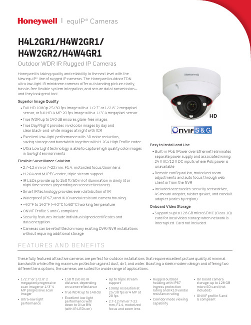
equIP® Cameras|H4L2GR1/H4W2GR1/H4W2GR2/H4W4GR1Outdoor WDR IR Rugged IP CamerasHoneywell is taking quality and reliability to the next level with theNew equIP® line of rugged IP cameras. The Honeywell outdoor TDNultra low‑light IR minidome cameras offer outstanding picture clarity, hassle‑free flexible system integration, and secure data transmission—and they look great too!Superior Image Quality• F ull HD 1080p 25/30 fps image with a 1/2.7" or 1/2.8" 2 megapixel sensor, or full HD 4 MP 20 fps image with a 1/3" 4 megapixel sensor • True WDR up to 140 dB ensures glare‑free images• T rue Day/Night provides vivid color images by day andclear black‑and‑white images at night with ICR• E xcellent low‑light performance with 3D noise reduction,saving storage and bandwidth together with H.264 High Profile codec • U ltra Low Light technology is able to capture high quality color images in low light environmentsFlexible Surveillance Solution• 2.7–12 mm or 7–22 mm, F1.4, motorized focus/zoom lens• H.264 and MJPEG codec, triple stream support• I R LEDs provide up to 150 ft (50 m) of illumination in dimly lit ornighttime scenes (depending on scene reflectance)• Smart IR technology provides even distribution of IR• Waterproof (IP67) and IK10 vandal resistant camera housing• –40°F to 140°F (–40°C to 60°C) working temperature• ONVIF Profile S and G compliant• S ecurity features include individual signed certificates anddata encryption• C ameras can be retrofitted on many existing DVR/NVR installations without requiring additional storageF E AT U R E S A ND B E NE F I T S• 1/2.7" or 1/2.8" 2 megapixel progressive scan imager or 1/3" 4 MP progressive scan imager• Ultra-low light performance • 150 ft (50 m) IRdistance, dependingon scene reflectance• True WDR: up to 140 dB• Excellent low lightperformance withdown to 0 lux BW(with IR LEDs on)• Up to triple streamsupport• 1080p resolution at25/30 fps or 4 MP at20 fps• 2.7-12 mm or 7-22mm, F1.4, motorizedfocus and zoom lens• Rugged outdoorhousing with IP67ingress protectionrating and IK10 vandalresistance rating• Corridor mode viewingcapability• On board camerastorage: up to 128 GBmicro SD card (notincluded)• ONVIF profile S andG compliantEasy to Install and Use• B uilt‑in PoE (Power over Ethernet) eliminatesseparate power supply and associated wiring;24 V AC/12 V DC inputs where PoE power isunavailable• R emote configuration, motorized zoomadjustments and auto focus through webclient or from the NVR•I ncluded accessories: security screw driver,4S mount adapter, rubber gasket, and conduitadapter (varies by region)Onboard Video Storage• S upports up to 128 GB microSDHC (Class 10)card for local video storage when network isinterrupted. Card not included.These fully featured attractive cameras are perfect for outdoor installations that require excellent picture quality at minimal bandwidth while offering maximum protection against dust, dirt, and water. Boasting a sleek modern design and offering two different lens options, the cameras are suited for a wide range of applications.HDDIME N S ION SThe camera can be configured to automatically detect and respond to events such as motion in the scene, alarm inputs, network failure, and/or camera tampering. Automated responses include: sending a notification through email, FTP, and/or HTTP; sending a still image of the event through email and/or FTP; and recording a video clip of the event to a configuredmicroSDHC card. Setup can be done through a web client or from an NVR.SPEC IF IC AT IONSNotes:* S ome development may be required in specific user cases to support some of these protocols in the field as they mature over time.OR DE RINGFor more information /securityHoneywell Security and Fire2700 Blankenbaker Pkwy, Suite 150 Louisville, KY 402991.800.323.4576 Honeywell reserves the right, without notification, to make changes in product design or specifications.L/H4OWDRCD/D | 06/16© 2016 Honeywell International Inc.。
Honeywell TD系列线性温度传感器说明书

INTRODUCTIONLinear temperature sensors have a major advantage. The output can be easily con-ditioned to achieve a desired voltage out-put span over a particular temperature range. A linear output voltage allows ease of interface to data acquisition systems and programmable controllers. B y ad-justing the circuit gain, the sensitivity of the output can be adjusted over the total range such as 10°to +40°C.INTERFACING WITH 1-5V CIRCUITIf more than 1mA of current flows through the TD, self-heating will occur. The self-heating effect is typically 0.2°C/milliwatt. The circuits in Figure 1and Figure 2pro-vide a maximum current flow of 1mA.SETTING DESIRED SPANThe circuit gain depends on the temper-ature range you want to sense. The offset adjustment is, in turn, dependent on the chosen gain. The transfer function for both circuits (Figures 1and 2) is as fol-lows:(R5/R4+1) ɀV[R TD/(R TD+R7)] -(R5/R4)(1+R3/R2)V1⍧v OOnly two elements are unknown: the off-set (v1), and the circuit gain (R5/R4+1). To set the desired span, two equations for the two unknowns must be created and solved. To simplify these calculations, the following assumption is made:R5/R4⍧R2/R3The second assumption is that no self-heating of the TD element will occur: thevalues of V and R7are constant at thevalues indicated.V[R TD/(R TD+R7)] ⍧5[R TD/(R TD+5110)]These assumptions reduce the transferfunction to:(R5/R4+1) ɀ5[R TD/(R TD+5110)] -(R5/R4+1)v1⍧v OTo create the first of the two simultaneousequations, the value of R TD for the desiredminimum temperature is taken fromTable 1. (R TD at 20°C equals 2000 Ohms,and v O⍧1V.) For the second equation,the value of R TD for the desired maximumtemperature is taken from the table, andv O⍧5 V.The two equations are then solved for thegain (R5/R4+1) and the offset (v1). Thefollowing example shows how this is ac-complished.Desired temperature range: 0°to 60°C.Voltage output over range: 1to 5 V.Equation 1: R TD at 0°C is 1854 Ohms.(R5/R4+1) ɀ5[1854/(1854 +5110)] - (R5/R4+1)v1⍧1VEquation 2: R TD at 60°C is 2314 Ohms.(R5/R4+1) ɀ5[2314/(2314 +5110)] - (R5/R4+1)v1⍧5 VStep 1: subtract equation 1from equation2.(R5/R4+1)(1.558) - (R5/R4+1)V1⍧5(R5/R4+1)(1.331) - (R5/R4+1)v1⍧1(R5/R4+1)(.227) - 0 ⍧4(R5/R4+1) ⍧4(1/.227)(R5/R4+1) ⍧17.62 ⍧GAINStep 2: substitute (R5/R4+1) ⍧17.62 intoequation 1and solve for V1.(17.62)(1.331) - (17.62)v1⍧123.454 - 17.62v1⍧122.452 ⍧17.62v11.274 ⍧v1⍧OFFSETIn order to transfer this information intothe circuit in Figure 1, choose appropriatevalues for R4and R5such that:(R5/R4+1) ⍧GAINFor this example, R4⍧1K Ohm and R5⍧16.62 K Ohm would be appropriate.Choose R2and R3based on R2/R3⍧R5/R4.For this example, choose R2⍧R5⍧16.62K Ohm, and R3⍧R4⍧1K Ohm.To set the offset v1using potentiometer R1,temporarily insert an equivalent discreteresistor in place of the TD element. Itshould be equal to the TD resistance atthe minimum desired temperature (1854Ohms from the example). Adjust R1untilthe output voltage is 1V. Replace thediscrete resistor with the TD element. Thecircuit is now set and ready to give 1V to 5V output over the chosen temperaturerange.HoneywellɀSensing and Controlɀ1-800-537-6945 USAɀ⍣1-815-235-6847 Internationalɀ1-800-737-3360 Canada133134Honeywell ɀ Sensing and Control ɀ1-800-537-6945 USA ɀ⍣1-815-235-6847 International ɀ1-800-737-3360 CanadaFigure 15.0 V Regulated Circuit1.LM358 is a general purpose oper-ational amplifier.2.2N2222 is a general purpose NPN transistor.3.Resistor accuracy should be within ±1%.4.v Ois measured with respect to ground.Figure 26.5-30 V Supply VoltageNote: Any error on the 5.0 V regulator will be seen directly on v O . This error can be reduced when setting the span by as-suming that V equals the actual output ofthe regulator.Figure 3TD Series Resistance vs TemperatureABSOLUTE MAXIMUM RATINGSOperating temperature range −40 to +150°C (−40 to +302°F)Storage temperature range −55 to +170°C (−67 to +338°F)Voltage10 VDC Continuous (24 hours)Linearity±2% (−25 to 85°C)±3% (−40 to 150°C)TD sensors can be linearized to within ±0.2%.Re pe atability ±1ȉHoneywell ɀ Sensing and Control ɀ1-800-537-6945 USA ɀ⍣1-815-235-6847 International ɀ1-800-737-3360 Canada 135ELECTRICAL INTERFACINGThe high nominal resistance, positive temperature coefficient and linear sensi-tivity characteristics of TD Series temper-ature sensors simplify designing the elec-trical interface.Figure 4 is a simple circuit that can be used to linearize the voltage output to within 0.2% or a ±0.4°C error over a range of −40°to +150°C (−40°to +302°F).Figure 5 illustrates an interface for appli-cations requiring a voltage that varies lin-early with temperature. In the example shown, the current regulator sensor re-sistance can be affected by temperature,so only the temperature sensor should be exposed to thermal changes.In some applications, it may be desirable to detect one particular temperature. Fig-ure 6 illustrates one way this can be ac-complished. In the comparator circuit shown, the potentiometer can be adjust-ed to correspond to the desired temper-ature.Figure 4Linear Output Voltage CircuitTable 1– INTERCHANGEABILITY (with 1m A maximum current)Temperature Resistance (Ohms)Temperature Resistance (Ohms)−40°C (−40°F)1584 ±12 (1.9°C)+60°C (140°F)2314 ±9 (1.1°C)−30°C (−22°F)1649 ±11 (1.7°C)+70°C (158°F)2397 ±10 (1.2°C)−20°C (−4°F)1715 ±10 (1.5°C)+80°C (176°F)2482 ±12 (1.4°C)−10°C (14°F)1784 ±9 (1.3°C)+90°C (194°F)2569 ±14 (1.6°C)0°C (32°F)1854 ±8 (1.1°C)+100°C (212°F)2658 ±16 (1.8°C)+10°C (50°F)1926 ±6 (0.8°C)+110°C (230°F)2748 ±18 (2.0°C)+20°C (68°F)2000 ±5 (0.7°C)+120°C (248°F)2840 ±19 (2.0°C)+30°C (86°F)2076 ±5 (0.7°C)+130°C (266°F)2934 ±21 (2.2°C)+40°C (104°F)2153 ±6 (0.8°C)+140°C (284°F)3030 ±23 (2.4°C)+50°C (122°F)2233 ±7 (0.9°C)+150°C (302°F)3128 ±25 (2.5°C)Equation for computing resistance:R T ⍧R O +(3.84 ×10⁻³×R O ×T) +(4.94 ×10⁻⁶×R O ×T 2)R T ⍧Resistance at temperature T R O ⍧Resistance at 0°C T ⍧Temperature in °CFigure 5Simple Current Regulator InterfaceFigure 6Adjustable Point (Comparator) InterfaceReference/Index。
- 1、下载文档前请自行甄别文档内容的完整性,平台不提供额外的编辑、内容补充、找答案等附加服务。
- 2、"仅部分预览"的文档,不可在线预览部分如存在完整性等问题,可反馈申请退款(可完整预览的文档不适用该条件!)。
- 3、如文档侵犯您的权益,请联系客服反馈,我们会尽快为您处理(人工客服工作时间:9:00-18:30)。
跳线设置:
跳线 J1
J2
J3
位置 OFF ON
5 12 5 12
缺省值 *
* *
表示 端口1 RS-485未使用终端电阻 端口1 RS-232使用终端电阻 读卡器1 5V供电 读卡器1 12V供电 读卡器2 5V供电 读卡器2 12V供电
版权所有©霍尼韦尔国际公司 3
霍尼韦尔安防
DIP开关设置:
S8 S7 S6 S5 S4 S3 S2 S1
霍尼韦尔安防
(RMA)后才能返回厂家。从出厂之日起,Engineered Systems产品有两年的保修期,保修期内,更换故障零件及人工 费全免。但终端设备、打印机、通信产品、升级产品的保质期为90天。保修期内的免费维修只限于产品正常使用。若 由于错误使用、不当贮藏、不当安装、操作或修理、更改、替换、事故、异常损坏或其他物理环境造成产品损坏,则 不在保修之列。
运行模式
LED D79
LED D80
说明
上电时
亮
灭
上电启动,硬件设置
灭
亮
测试RAM
亮
亮
测试ROM,完成初始化
闪
亮
启动完成,D79闪四次
正常运行
闪烁
系统被激活后每秒闪一次。 若亮的时间长一点(0.8秒亮,0.2秒 灭),表示模块处于离线状态,与主控 模块的通信中断;若灭的时间长一点, 表示模块在线,与主控模块的通信正 常。
双读卡器模块的I/O端子只为控制两个门而配置的。插在插板式安装箱中,从下往上端口依次是电源、与主控模块 (PRO22IC)的通信接口、读卡器2接口、与读卡器2相关的I/O接口(称为门磁和开门按钮的输入点,和控制电锁的继 电器输出)、读卡器1接口、与读卡器1相关的I/O接口,最上面的端子是两个额外的可自由使用的通用报警输入端子。
警告及提示
警告
安装前,请断开所有外部供电电源。 在给设备上电前,请确认电源的供电电压在设备要求的电压范围内。 在设备未安装完毕前,不要给系统上电。 请勿必遵守此警告,否则可能会造成人身伤亡和设备损坏。
警告
消防及安全性提示 在使用读卡器的关键出入口、消防通道、栏杆、电梯等,根据消防和安全条例的要求,必须安装有其他的应急出口。 这些防火和安全条例各地不尽相同,所以采用电子设备控制门或其他通道系统时,必须取得当地消防机构的认可。例 如,使用出门按钮,在某些地区,可能是不可法的。在许多应用场所,出门指示要清晰明了,一看就懂,容易使用, 而不需要事前告知,这是安全条例的要求。所有的许/认可要以书面方式确认。不要接受口头的认可,口头认可不具有 法律效律。 Engineered Systems不建议使用PRO2200 或 相关产品作为主要的报警监控系统。主要的报警监控系统应该符合当地消 防和安全条例的要求。安装商必须定期对系统进行测试,并指导最终用户进行适当的日常测试。 不做定期的测试维护,当最终用户出现使用问题时,安装商应对造成的损失负有责任。
保密性
所有由Engineered Systems提供,用于产品设计、使用和销售的软件、制图、图表、规范、说明、手册等资料,都是 保密的,归Engineered Systems所有,用户不得用于其他产品研发。
描述
双读卡器模块支持两个门的控制,提供读卡器接口,可以是Weigend或Clock/Data,还有输入点和继电器输出。如果这 个模块是竖直插在安装箱中,那么只有一侧可以接线。选用平装机箱,双读卡器模块的所有端子都能使用,但平装机 箱内能容纳的模块数量就非常少。
霍尼韦尔安防
PRO-2200 双读卡器模块安装手册 (PRO22R2)
目录
警告及提示 ...................................................................1 声明 .........................................................................2 拆包装程序 ...................................................................2 运输指导 .....................................................................2 保修期 .......................................................................2 保密性 .......................................................................3 描述 .........................................................................3 设置 .........................................................................3 LED 指示灯 ...................................................................4 电源 .........................................................................4 通信 .........................................................................5 读卡器连线 ...................................................................5 报警输入连线 .................................................................6 控制输出连线 .................................................................6 安装说明 .....................................................................6 推荐安装步骤 .................................................................7 参数总录 .....................................................................7
提醒
本手册未经Engineered Systems的同意和书面授权,不得复制,使用,或提供给其他地方印制。本手册及产品中的信 息为商业机密,属Engineered Systems公司所有。美国版权法保护资料及软件产口品的所有信息。
提醒
此产品的使用被视为已同意接受Engineered Systems的软件使用条款。请从Engineered Systems申请复印件,仔细阅 读。
警告
所有外箱必须正确接地。
警告
所有电锁需做电磁保护,可安装S-4。Engineered Systems建议用户选用使用直流供电的电锁。 本手册可以在未通知的情况下进行更改。
版权所有©霍尼韦尔国际公司 1
霍尼韦尔安防
提醒
若运输过程中造成损坏,请在索赔中填写承运商。
提醒
静电可损坏CMOS集成电路和模块。 为防止静电破坏需遵循以下操作: 在运送所有电子设备,包括已安装的读卡器,使用防静电所装袋或防静电容器。 接触所有对静电敏感的器件时,要在有静电防护的工作台上进行。工作台有专门的桌垫、地垫及静电环。工作台不限 供应商。
当与主控模块的通信中断时,读卡器模块可以识别区域码(Facility Code)控制开门,通用输出保持通信中断时的设 置模式。每个双读卡器模块可保存8个区域码;键盘输入要跟随在读卡器输入之后,与读卡数据组合发出。
设置
双读卡器模块的设置通过跳线和一组8位拨码开关。这些跳线和开关用来总线终端电阻、读卡器供电电压,模块地址, 及通信速率。具体方法参见下面的表格:
声明
当用户收到由于产品或产品元件导致人员受伤或财产损失的投诉事件时,应立即将所有要求以书面形式通知 Engineered Systems公司。
拆包装程序
提醒
在拆包装前若发现任何运输中出现的损坏,在索赔中填写承运商。 所有外包装请小心打开,使里面的设备不要受损。 以下是打开设备包装,准备安装的步骤: 1. 打开外包装,去除所有包裹材料,保留这些包装,以备以后邮寄用。 2. 检查货物是否齐全,若有缺少物品,请立即联系订购部门。 3. 检查货物是否完好,若发现有损坏,请按下面执行:如果损坏为运输过程所为,在申诉单上一定要填写商业承运 人。如果是其他故障,请要求返回认可。
OFF ON OFF OFF OFF 地址8
OFF OFF
保留
OFF ON
9,600 BPS
ON OFF
19,200 BPS
ON ON
38,400 BPS
OFF
未使用*
* = 缺省值
LED 指示灯
读卡器模块上有两个LED指示灯 D79 和 D80,在上电启动和运行提供状态指示。
CNOITPIRCSED
提醒
此设备已经测试,符合有关FCC规定 第15部分,关于A类数字设备的内容。这部分内容制定是为了保证设备在商业环境 中使用时,能够提供对有害干扰的有效保护。此设备产生、使用,并能发射无频频率能量,如未按说明书进行安装及 使用,可以会导致对无线通信的干扰。在居民区操作此设备,用户可能被要求自行支付用于校正干扰所需的费用。
保修期
Engineered Systems所售产品都含有一个保修登记卡,最终用户将之寄回Engineered Systems,Engineered Systems 可凭此提供产品的保修服务、维修或更换。所有要返修的产品应先通知Engineered Systems,并取得返回许可号
