STF202中文资料
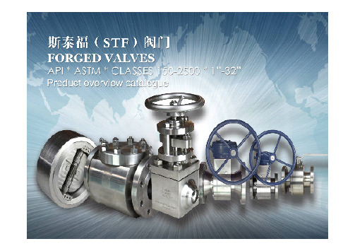
STF氧气阀门应用V1
阀门 的连接 氧气专用 氧气专用阀门 阀门的连接
①氧气管道的连接,应采用焊接,但与设备、阀门连接可采 用法兰式、丝扣连接。丝扣连接片,应采用一氧化铅、水玻 璃或聚四氟乙烯薄膜作为填料,严禁用涂铅用的麻或棉丝, 或其他含油脂的材料。 ②氧气管道应有导除静电的接地装置。厂区管道可在管道分 岔处无分支管道每80~100m处以及进出车间建筑物处设一接 地装置。直接埋地管道可在埋地之前及出地后各接地一次; 车间内部管道,可与本车间的静电干线连接,接地电阻值应 符合规范。当每对法兰或螺纹接头间电阻值超过0.03Ω时, 应设跨接导线。对有阴板保护的管道,不应作接地。 ③氧气管道的弯头、分叉头,不应紧接安装在阀门的下游, 阀门的下游侧宜设长度不小于管外径5倍的直管段。
氧气阀气缓冲阀 介质:氧气,氮气。 温度:50-425度左右 压力:1.0-14.7Mpa 特点:禁油,脱脂,防静电 介质特点:易燃易爆,
氧气专用阀应用方案
/截止阀 /止回阀 阀门种类:高温金属硬密封球阀 高温金属硬密封球阀/ 截止阀/ 口径/压力等级: 1/2”-12” 1000LBS 温度:-45℃-480℃ 压力:150-1500LBS 介质:氧气、氮气、氢气、氩气、乙炔 阀体、阀盖:316/ Incoloy625 内件: Incoloy625/ Inconel625/Inconel800系列
STF氧气专用切断阀介绍
多种形式,有T型截止阀、球阀、止回阀,适用于各 种气体。 氧气阀门阀体选材最低304不锈钢,煤浆气化氧气阀 , 常用材料阀体Incoloy625 ,Inconel625 625, Inconel800系列,阀芯至少Incoloy625。 STF氧气阀从零部件加工开始,严格执行禁油程序, 静电导出设计,防火标准符合API一607的要求;组装 前作禁油处理,阀门在出厂前高温去油,用碱性脱脂 液进行脱脂。阻燃性好,导电性能好,传热快,结构紧 凑, 安全可靠 。
TF202中文资料
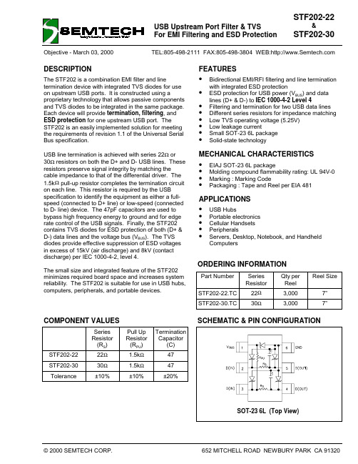
FEATURES• Bidirectional EMI/RFI filtering and line termination with integrated ESD protection• ESD protection for USB power (V BUS ) and data lines (D+ & D-) to IEC 1000-4-2 Level 4• Filtering and termination for two USB data lines • Different series resistors for impedance matching • Low TVS operating voltage (5.25V)• Low leakage current• Small SOT-23 6L package •Solid-state technologyMECHANICAL CHARACTERISTICS • EIAJ SOT-23 6L package• Molding compound flammability rating: UL 94V-0• Marking : Marking Code• Packaging : Tape and Reel per EIA 481APPLICATIONS • USB Hubs• Portable electronics • Cellular Handsets • Peripherals• Servers, Desktop, Notebook, and HandheldComputersDESCRIPTIONThe STF202 is a combination EMI filter and linetermination device with integrated TVS diodes for use on upstream USB ports. It is constructed using aproprietary technology that allows passive components and TVS diodes to be integrated in the same package.Each device will provide termination, filtering , and ESD protection for one upstream USB port. The STF202 is an easily implemented solution for meeting the requirements of revision 1.1 of the Universal Serial Bus specification.USB line termination is achieved with series 22Ω or 30Ω resistors on both the D+ and D- USB lines. These resistors preserve signal integrity by matching the cable impedance to that of the differential driver. The 1.5k Ω pull-up resistor completes the termination circuit on each line. This resistor is required by the USB specification to identify the equipment as either a full-speed (connected to D+ line) or low-speed (connected to D- line) device. The 47pF capacitors are used to bypass high frequency energy to ground and for edge rate control of the USB signals. Finally, the STF202contains TVS diodes for ESD protection of both (D+ &D-) data lines and the voltage bus (V BUS ). The TVS diodes provide effective suppression of ESD voltages in excess of 15kV (air discharge) and 8kV (contact discharge) per IEC 1000-4-2, level 4.The small size and integrated feature of the STF202minimizes required board space and increases system reliability. The STF202 is suitable for use in USB hubs,computers, peripherals, and portable devices.Part Number Series Resistor Qty per Reel Reel SizeSTF202-22.TC 22Ω3,0007”STF202-30.TC30Ω3,0007”ORDERING INFORMATIONCOMPONENT VALUESSeries Resistor (R S )Pull Up Resistor (R PU )Termination Capacitor (C)STF202-2222Ω 1.5k Ω47STF202-3030Ω 1.5k Ω47Tolerance±10%±10%±20%MAXIMUM RATINGSRating Symbol Value UnitSteady-State Power P100mW ESD Air Discharge per IEC 1000-4-2VPP16kVESD Contact Discharge per IEC 1000-4-2VPP10kVLead Soldering Temperature (10 seconds)TL260°COperating Temperature Tstg-40 to +125°CStorage Temperature Tj-55 to +150°C ELECTRICAL CHARACTERISTICS (T = 25ºC Unless Otherwise Noted)STF202-xxParameter Symbol Conditions Minimum Nominal Maximum UnitsTVS Reverse Stand-Off Voltage VRWM5.25VTVS Reverse Breakdown Voltage VBR It= 1mA6VTVS Reverse Leakage Current IR VRWM= 5.25V, T=25°CBetween VBUSpin andground5µATVS Reverse Leakage Current IRVRWM= 3.3V, T=25°CBetween any data(D+, D-) pin and ground1µATotal TVS Junction Capacitance Cj Between I/O pins andGnd, each deviceVR= 0V, f = 1MHz10pFSeries Resistor (STF202-22)R S Each Line202224ΩSeries Resistor (STF202-30)R S Each Line273033ΩPull Up Resistor RUPEach Line 1.35 1.5 1.65kΩCapacitor C Each Line47pFTotal Capacitance CTOT Between I/O pins andGnd, each lineVR= 0V, f = 1MHz60pFPart Number Marking Code STF202-22222 STF202-30230 MARKING CODESESD Clamping (15kV Air) ESD Clamping (8kV Contact)Insertion Loss CharacteristicsAnalog Crosstalk (D+ to D-)0 dB0.030 MHz 1 GHzFigure 1 - STF202 Circuit DiagramDevice ConnectionThe STF202 is designed to provide termination, EMI filtering and ESD protection for two USB I/O lines. The equivalent circuit diagram is shown in Figure 1. The device is connected as follows:1. Full-Speed Devices: For full-speed devices thepull-up resistor is connected to the D+ line. Pin 1is connected to the voltage supply line (V BUS ). The input of the D+ line is routed into pin 3 and out of pin 4. The input of the D- line is connected at pin 2and the output at pin 5. Pin 6 is connected to ground.• Low-Speed Devices: For low speed devices thepull-up resistor is connected to the D- line. Pins 1is connected to the voltage supply line (V BUS ). The input of the D- line is connected at pin 3 with the output taken at pin 4. The input of the D+ line is connected to pin 2 and the output is at pin 5. Pin 6is connected to ground.USB Port Design ConsiderationsThe Universal Serial Bus (USB) specification requires termination and filtering components for proper operation. In addition, an open USB socket isvulnerable to hazardous ESD discharges in excess of 15kV. These discharges can may occur on the data lines or the voltage bus. The STF202 is an easilyimplemented solution designed to meet the termination & EMI filter requirements of the USB specification revision 1.1. It also provides ESD protection to IEC 61000-4-2, level 4.A simplified USB port is shown in Figure 3. USB line termination is achieved with series resistors on both the D+ and D- lines. These resistors preserve signalintegrity by matching the cable impedance to that of the differential driver. 15k Ω pull-down resistors are used to identify a downstream port while an upstream port is identified with a 1.5K Ω pull up resistor on either the D+(full speed devices) or the D- (low speed devices) data line. Capacitors are used to bypass high frequency energy to ground and for edge rate control of the USB signals. TVS diodes are added for ESD protection of both (D+ & D-) data lines and the voltage bus (V BUS ). A power distribution switch and voltage regulator provide the power management functions of the port.Semtech provides a complete solution to simplify USB port design (Figure 4). The STF201 & STF202Figure 2 - STF202 Connection Diagram(Full Speed Devices)123456integrate all of the components necessary for line termination, bidirectional EMI filtering, and ESD protection on downstream (STF201) or upstream (STF202) ports. The SC5826 is a dual port power switch that provides individual or ganged portswitching, fault reporting, and inrush current limiting as required by the USB specification. The SC5205 ULDO provides a stable voltage to the USB controller.Board Placement & Layout Guidelines.Designing a USB hub to meet EMI & ESD immunity requirements requires a combination of optimumcomponent placement, trace routing, and good circuit design practices. Some general guidelines are given below:• Avoid running D+ & D- signal line traces near high speed clock lines or similar signal lines.• Avoid running critical signal lines near board edges.• Locate the USB controller chip near the USB connectors.• Place the STF202 near the USB connector to restrict transient coupling.•Minimize the path length between the USBconnector and the STF202Figure 4 - Typical USB Hub DesignOUTLINE DRAWING SOT23-6LLAND PATTERN SOT23-6L。
ST4ETA102;ST4ETA103;ST4ETA202;ST4ETB102;ST4ETA502;中文规格书,Datasheet资料
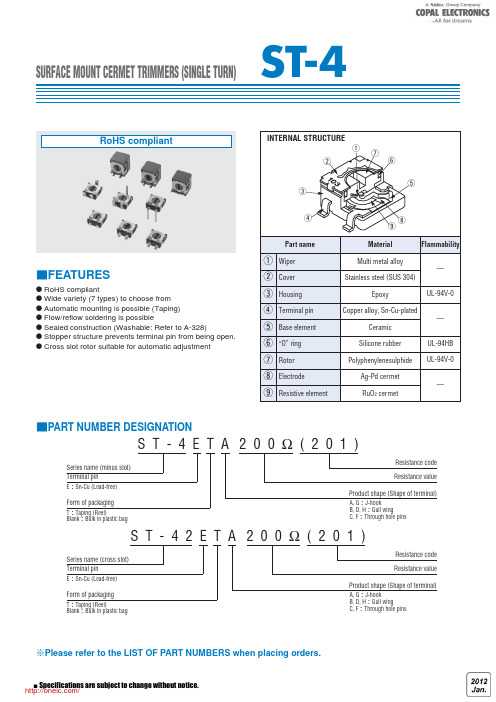
SURFACE MOUNT CERMET TRIMMERS (SINGLE TURN)● RoHS compliant● Wide variety (7 types) to choose from ● Automatic mounting is possible (Taping)● Flow/reflow soldering is possible● Sealed construction (Washable: Refer to A-328)● Stopper structure prevents terminal pin from being open.● Cross slot rotor suitable for automatic adjustmentFEATURESPART NUMBER DESIGNATIONPlease refer to the LIST OF PART NUMBERS when placing orders.S T - 4 E T A 2 0 0Ω( 2 0 1 )Series name (minus slot)Form of packagingT Taping (Reel)Blank Bulk in plastic bagTerminal pinE Sn-Cu (Lead-free)Form of packagingT Taping (Reel)Blank Bulk in plastic bagTerminal pinE Sn-Cu (Lead-free)Resistance code Resistance valueProduct shape (Shape of terminal)A, G J-hookB, D, H Gull wingC, F Through hole pinsS T - 4 2 E T A 2 0 0Ω( 2 0 1 )Series name (cross slot)Resistance code Resistance valueProduct shape (Shape of terminal)A, G J-hookB, D, H Gull wingC, F Through hole pinsST-4LIST OF PART NUMBERS Nominal resistance valuesR/R Change in total resistanceS.S. Setting stabilityMAXIMUM INPUT RATINGSRECOMMENDED P.C.B. PAD OUTLINE DIMENSIONS(Unit: mm)● ST-4EA● ST-4EG● ST-4EH● ST-4EB● ST-4EDNote) The zero point is the center of mounting.The products indicated by Amark are manufactured uponreceipt of order basis.OUTLINE DIMENSIONSUnless otherwise specified, tolerance : ±0.3 (Unit: mm)● ST -4EATop adjustment● ST● ST Top adjustmentNote the terminal position.13● ST -4EGSide adjustment● ST -4EFRear adjustment● ST -4EHSide adjustment● ST -4EDRear adjustmentNote the terminal position.Semi-standard productsSemi-standard products● ST -42ECROSS SLOT DIMENSION13OUTLINE DIMENSIONSUnless otherwise specified, tolerance : ±0.3 (Unit: mm)<Bulk pack specifications>● Unit of bulk in a plastic bag is 100 pcs. per pack.● Boxing of bulk in a plastic bag is performed with 500pcs. per box.PACKAGING SPECIFICATIONS<Taping packaging specifications>● Taping version is packaged in 500 pcs. per reel.Orders will be accepted for units of 500 pcs., i.e., 500,1000, 1500 pcs., etc.● ST-4ETA, ETB and ETD versions are boxed with 4 reels (2000 pcs.).ST-4ETG and ETH versions are boxed with one reel (500 pcs.).Maximum number of consecutive missing pieces = 2Leader length and reel dimension are shown in the dia-grams below.● EMBOSSED TAPE DIMENSIONS● REEL DIMENSIONSConforms to JIS C 0806-3In accordance with EIAJ ET-7200A(Unit: mm)● ST -4ETA/ETB/ETD● ST -4ETG/ETHHeadEndDirection of feedInstallation example Direction of feed分销商库存信息:COPAL-ELECTRONICSST4ETA102ST4ETA103ST4ETA202 ST4ETB102ST4ETA502ST4ETB101 ST4ETA203ST4ETA503ST4ETB103 ST4ETB502ST4ETB503ST4ETB202 ST4ETB203ST4ETA501ST4ETB201 ST4ETB104ST4ETA104ST4ETA105 ST4ETA204ST4ETB501ST4ETA101 ST4ETA201ST4ETA500ST4ETA504 ST4ETB204ST4ETB500ST42ETA100 ST42ETA101ST42ETA102ST42ETA103 ST42ETA104ST42ETA105ST42ETA200 ST42ETA201ST42ETA202ST42ETA203 ST42ETA204ST42ETA205ST42ETA500 ST42ETA501ST42ETA502ST42ETA503 ST42ETA504ST42ETB100ST42ETB101 ST42ETB102ST42ETB103ST42ETB104 ST42ETB105ST42ETB200ST42ETB201 ST42ETB202ST42ETB203ST42ETB204 ST42ETB205ST42ETB500ST42ETB501 ST42ETB502ST42ETB503ST42ETB504 ST4ETA205ST4ETB105ST4ETB205 ST4ETB504ST4EC101ST4EC102 ST4EC103ST4EC104ST4EC105 ST4EC201ST4EC202ST4EC203 ST4EC204ST4EC205ST4EC500 ST4EC501ST4EC502ST4EC503 ST4EC504ST4ETA100ST4ETB100 ST4EC100ST4EC200ST42EC100 ST42EC101ST42EC102ST42EC103 ST42EC104ST42EC105ST42EC200 ST42EC201ST42EC202ST42EC203 ST42EC204ST42EC205ST42EC500 ST42EC501ST42EC502ST42EC503 ST42EC504ST4ETG100ST4ETG101 ST4ETG102ST4ETG103ST4ETG104 ST4ETG105ST4ETG200ST4ETG201 ST4ETG202ST4ETG203ST4ETG204 ST4ETG205ST4ETG500ST4ETG501 ST4ETG502ST4ETG503ST4ETG504 ST4ETH100ST4ETH101ST4ETH102 ST4ETH103ST4ETH104ST4ETH105 ST4ETH200ST4ETH201ST4ETH203 ST4ETH205ST4ETH500ST4ETH501 ST4ETH502ST4ETH503ST4ETH504。
CSD-213系列光纤纵联差动保护测控装置说明书(0SF .451.093)_V1.01新
5 CSD-213A 光纤纵联差动线路保护测控装置 ............................. 13
5.1
装置简介 ................................................................................................................................. 13
2.5
安全性能 .................................................................................................................................... 3
2.6
热性能(过载能力) ................................................................................................................ 4
2.9
装置主要技术参数 .................................................................................................................... 4
3 装置硬件 ...........................................................6
CSD-213 系列光纤纵联差动保护测控装置 说明书
CSD-213 系列光纤纵联差动保护测控装置
技术说明书
编
制:戴晨翔
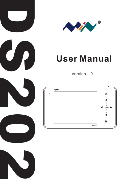
DS202用户手册说明书
ratings information before making connections to the device.
W a r n i n g
● Do not operate in wet/damp conditions. ● Do not operate in a potentially inflammable/explosive atmosphere. ● Please keep the surface of the product clean and dry.
Downward selection(Slide Down)
Reset Parameter(Tap Right/increase, slide Right)
Alter set up parameter(Tap Left/Reduce, Slide Left)
M
On/Off Sub-menu
Note that each item's color in Parameter Area is the same as that in Measurement Area
Chapter 4 Basic Function P14
Chapter 5 Product Inspection P20
Chapter 7 Technical Support P22
Chapter 6 Battery Disposal P21
This user manual is based onAPP V1.28
●
W a r n i n g Use proper power cord. Please use power cord specified for this product and
ST202中文资料

1/10June 2001s SUPPLY VOLTAGE RANGE: 4.5 TO 5.5V s SUPPLY CURRENT NO LOAD (TYP): 1.5mA sTRASMITTER OUTPUT VOLTAGE SWING (TYP): ± 9Vs TRANSITION SLEW RATE (TYP .): 12V/µs sRECEIVER PROPAGATION DELAY (TYP .): 0.1µss COMPATIBLE WITH MAX202s RECEIVER INPUT VOLTAGE RANGE: ± 30V s DATA RATE (TYP .): 400Kbp/ssOPERATING TEMPERATURE RANGE: -40 TO 85 °C, 0 TO 70°CDESCRIPTIONThe ST202 is a 2 driver, 2 receiver device following EIA/TIA-232 and V.28 communication standard. It is particularly suitable for applications where ± 12V is not available. The ST202 uses a single 5V power supply and only four external capacitors (0.1µF). Typical application are in:Portable Computers, Low Power Modems,Interfaces Translation, Battery Powered RS-232Networks.ORDERING CODESType Temperature Range PackageCommentsST202CN 0 to 70 °C DIP-1625parts per tube / 40tube per box ST202BN -40 to 85 °C DIP-1625parts per tube / 40tube per box ST202CD 0 to 70 °C SO-16 (Tube)50parts per tube / 20tube per box ST202BD -40 to 85 °C SO-16 (Tube)50parts per tube / 20tube per boxST202CDR 0 to 70 °C SO-16 (Tape & Reel)2500 parts per reel ST202BDR -40 to 85 °C SO-16 (Tape & Reel)2500 parts per reelST202CW 0 to 70 °C SO-16 Large (Tube)49parts per tube / 25tube per box ST202BW -40 to 85 °C SO-16 Large (Tube)49parts per tube / 25tube per boxST202CWR 0 to 70 °C SO-16 Large (Tape & Reel)1000 parts per reel ST202BWR -40 to 85 °C SO-16 Large (Tape & Reel)1000 parts per reel ST202CTR 0 to 70 °C TSSOP16 (Tape & Reel)2500 parts per reel ST202BTR-40 to 85 °CTSSOP16 (Tape & Reel)2500 parts per reelST2025V POWERED MULTI-CHANNEL RS-232 DRIVERS AND RECEIVERSST2022/10PIN CONFIGURATIONPIN DESCRIPTIONABSOLUTE MAXIMUM RATINGSAbsolute Maximum Ratings are those values beyond which damage to the device may occur. Functional operation under these condition is not implied.PlN N°SYMBOL NAME AND FUNCTION1C 1+Positive Terminal for the first Charge Pump Capacitor 2V+Doubled Voltage Terminal3C 1-Negative Terminal for the first Charge Pump Capacitor 4C 2+Positive Terminal for the second Charge Pump Capacitor 5C 2-Negative Terminal for the second Charge Pump Capacitor 6V-Inverted Voltage Terminal7T2OUT Second Transmitter Output Voltage 8R2IN Second Receiver Input Voltage 9R2OUT Second Receiver Output Voltage 10T2IN Second Transmitter Input Voltage 11T1IN First Transmitter Input Voltage 12R1OUT First Receiver Output Voltage 13R1IN First Receiver Input Voltage 14T1OUT First Transmitter Output Voltage 15GND Ground16V CCSupply VoltageSymbol ParameterValue Unit V CC Supply Voltage -0.3 to 6V V+Extra Positive Voltage(V CC -0.3) to 13.2V V-Extra Negative Voltage0.3 to -13.2V T IN Transmitter Input Voltage Range -0.3 to (V CC + 0.3)V R IN Receiver Input Voltage Range ± 30V T OUT Transmitter Output Voltage Range ± 15V R OUT Receiver Output Voltage Range -0.3 to (V CC + 0.3)VT SCTOUTShort Circuit Duration on T OUTinfiniteST2023/10ELECTRICAL CHARACTERISTICS(C 1 - C 4 = 0.1µF, V CC = 5V ± 10%, T A = -40 to 85°C, unless otherwise specified. Typical values are referred to T A = 25°C)TRANSMITTER ELECTRICAL CHARACTERISTICS(C 1 - C 4 = 0.1µF, V CC = 5V ± 10%, T A = -40 to 85°C, unless otherwise specified. Typical values are referred to T A = 25°C)Note 1: Measured from 3V to -3V or from -3V to 3V.Note2: One trasmitter output is loaded with R L = 3K Ω to 7K Ω, C L = 50 to 1000pFRECEIVER ELECTRICAL CHARACTERISTICS(C 1 - C 4 = 0.1µF, V CC = 5V ± 10%, T A = -40 to 85°C, unless otherwise specified. Typical values are referred to T A = 25°C)Note 1: RS-232 IN to TTL-CMOS OUT (from 50% to 50%)SymbolParameterTest ConditionsMin.Typ.Max.Unit I SUPPLY V CC Power Supply CurrentNo Load1.54mASymbol ParameterTest ConditionsMin.Typ.Max.Unit V TOUT Output Voltage Swing All Transmitter outputs are loaded with 3K Ω to GND ± 5± 9V I TIL Logic Pull-Up Current T IN = 0V540µA V TIL Input Logic Threshold Low 0.81.4V V TIH Input Logic Threshold High 1.42V SR TTransition Slew RateT A = 25°C,V CC = 5VR L = 3 to 7K Ω,C L = 50 to 2500pF(Note1)61230V/µsD R Data Rate(Note 2)200400Kbits/s R TOUT Transmitter Output ResistanceV CC = V+ = V- = 0V V OUT = ± 2V300ΩI SC Transmitter Output Short Circuit Currentone T XOUT to GND± 7± 22mA t dTPropagation Delay TimeTTL-CMOS IN to RS-232 OUT C L = 150pF (50% to 50%)1.33.5µsSymbol ParameterTest ConditionsMin.Typ.Max.Unit V RIN Receiver Input Voltage Operating Range-3030V R RIN RS-232 Input ResistanceT A = 25°C357K ΩV RILRS-232 Input Threshold Low0.81.3V V RIH RS-232 Input ThresholdHigh1.82.4V V RIHYS RS-232 Input Hysteresis V CC = 5V0.20.51V V ROL TTL/CMOS Output VoltageLowI OUT = 3.2mA (to V CC )0.20.4V V ROH TTL/CMOS Output VoltageHighI OUT = 1mA (to GND) 3.5V CC -0.2V I SCR Receiver Output ShortCircuit Current to GND to V CC2101030mA mA t dRPropagation Delay TimeC L = 150pF (Note 1)0.10.5µsST2024/10APPLICATION CIRCUITS (note 1, note 2)Note 1: C 1-4 capacitors can even be 1µF ones.Note 2: C 1-4 can be common or biased capacitors.CAPACITANCE VALUE (µF)C1C2.C3C4C50.10.10.10.10.1ST2025/10TYPICAL PERFORMANCE CHARACTERISTICS (unless otherwise specified T j = 25°C) Figure 1 : Driver Voltage Transfer CharacteristicsFigure 2 : Drive Short Circuit Output Current vs Temperature Figure 3 : Receiver Threshold vs Supply Voltage Figure 4 : Driver Output Capability Current vs Output VoltageFigure 5 : Driver Short Circuit Supply Current vs TemperatureFigure 6 : Receiver Threshold vs TemperatureInformation furnished is believed to be accurate and reliable. However, STMicroelectronics assumes no responsibility for the consequences of use of such information nor for any infringement of patents or other rights of third parties which may result from its use. No license is granted by implication or otherwise under any patent or patent rights of STMicroelectronics. Specifications mentioned in this publication are subject to change without notice. This publication supersedes and replaces all information previously supplied. STMicroelectronics products are not authorized for use as critical components in life support devices or systems without express written approval of STMicroelectronics.© The ST logo is a registered trademark of STMicroelectronics© 2000 STMicroelectronics - Printed in Italy - All Rights ReservedSTMicroelectronics GROUP OF COMPANIESAustralia - Brazil - China - Finland - France - Germany - Hong Kong - India - Italy - Japan - Malaysia - Malta - MoroccoSingapore - Spain - Sweden - Switzerland - United Kingdom© 10/10。
FC202系列标准负载变频器

持续 间歇/60秒
输 出容量 ( 2 0 8 V)
持续
最 大电缆横截面 ( 输入电源端, 电机输出端, 制动电阻端 )
最 大输入电流
持续 间歇/60秒
最 大外接输入快 熔(主电源)
环境 额 定最大负载时 的预计功率损 耗
重量 IP20
IP21
I P5 5 ,I P66
效率
[kW] [H P] [A] [A]
50℃运行环境温度
变 频器能在高达50℃的环境温度下达 到 最大的输出 ,在 最大55℃的环境 温 度下仍可降容运行。
VLT®FC202本 地控 制面板20 04年获 得 国际iF设计奖 ,在“界面 通讯” 类 来自34个国 家的1000项产 品中一 举夺魁。
直流电抗器
内置直流电抗器,有效降低电源的谐 波 干 扰 , 符 合 IEC-1000-3-2国 际标 准。设计紧凑、无需外部选件。
13 防腐蚀
具 有防腐蚀性的背 部散热通道组件 和 散 热片可以作为选 件订购,用于一 些 恶 劣的环境,例如 靠近海边的含盐 空 气中。
14 控制端子
专 门开发的笼式弹 簧夹紧端子增强 了 可靠性,而且便于调试和维护。
外壳封装
变 频器外壳封装符 合保 护等级IP20, 另 有 IP00, IP21, IP54, IP55和 IP66多种封装等级可选。
FC202系列 标准负载变频器
模 块 式V L T ®FC 2 0 2变 频 器
——使风机、水泵、以及轻过载型通用机械的控制省心省力、得心应手
用于泵和风机
在任 何工 业的泵 、风 机等 变转矩 应用
中, VLT®FC202系列变频器 都能 取得
较高 的传 动质量 和显 著的 节能效 果。
切克斯LPS202

LPS200系列直流稳压稳流电源中国专利号: ZL00201424.6ISO9001:2000注册号:00604Q10699RSO使用手册®北京切克斯电子科技有限公司 BEIJING TRADEX ELECTRONIC TECHNOLOGY CORP.安全●符号此标志为警告符号,提醒您按照使用手册使用。
●电源本设备交流供电电源电压有效值不应超过250伏特。
即两电源线之间及每根电源线与地之间交流电压有效值不应超过250伏特。
为保证安全工作,应保证电源电缆中的地线与保护地相连接。
●使用合适的电源电缆和设备的接地本设备通过电源电缆中的地线接地。
为了避免电击,使用本设备提供的电源电缆,将电源电缆插入适合的插座中,保证电源电缆中的地线与保护地相连接。
●不能在易燃、易爆环境下工作为了避免发生火灾、爆炸,在工作时及使用后1小时内严禁将设备放置在易燃、易爆环境中。
●不要移动盖板和面板本设备内有非安全电压,为了避免人身伤害,不要移动盖板和面板。
如需校准及维修应找专业校准及维修人员。
●不要触摸输出端子导电部位和负载导电部位本设备根据使用情况输出电压可能超过安全电压,使用时注意人身安全,严防触电。
在工作时及使用后1分钟内,不要触摸输出端子导电部位和负载导电部位避免电击。
●不要触摸散热器和盖板本设备在工作时散热器为散热体,在工作时及使用后1小时内请勿触摸散热器。
●在进行绝缘电阻和绝缘耐压测试时应注意在进行绝缘电阻和绝缘耐压测试时,高压电荷会被加到两测量点之间,测量之后应经过500K左右电阻泄放。
若不进行泄放,可能会发生电击。
若直接短路泄放,会造成设备损坏。
●请按指定方式使用如果设备不按指定方式使用,设备所提供的保护可能被削弱。
目录1.概述 ------------------------------------------------2.特点 ------------------------------------------------3.产品规格 --------------------------------------------4.使用条件 --------------------------------------------5.主要技术性能-----------------------------------------6.说明和防护措施 --------------------------------------7.面板装置 --------------------------------------------8.操作流程 --------------------------------------------9.使用方法 --------------------------------------------10.应用举例 -------------------------------------------11.工作原理 -------------------------------------------12.测试及校准 -----------------------------------------13.故障------------------------------------------------14.维护及质量保证 -------------------------------------15.成套说明 -------------------------------------------1.概述LPS200系列电源是一种多功能直流稳压稳流电源。
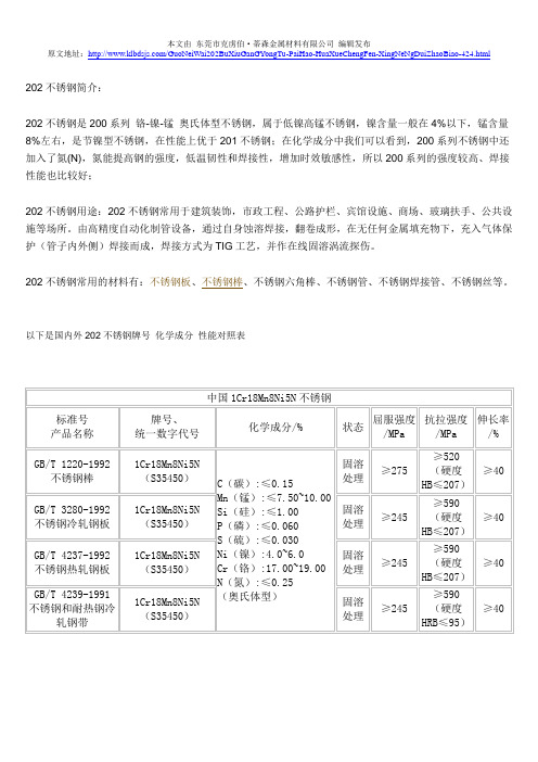
什么是202不锈钢及国内外202不锈钢牌号 化学成分 性能对照表
202不锈钢简介:
202不锈钢是200系列铬-镍-锰奥氏体型不锈钢,属于低镍高锰不锈钢,镍含量一般在4%以下,锰含量8%左右,是节镍型不锈钢,在性能上优于201不锈钢;在化学成分中我们可以看到,200系列不锈钢中还加入了氮(N),氮能提高钢的强度,低温韧性和焊接性,增加时效敏感性,所以200系列的强度较高、焊接性能也比较好;
202不锈钢用途:202不锈钢常用于建筑装饰,市政工程、公路护栏、宾馆设施、商场、玻璃扶手、公共设施等场所。
由高精度自动化制管设备,通过自身蚀溶焊接,翻卷成形,在无任何金属填充物下,充入气体保护(管子内外侧)焊接而成,焊接方式为TIG工艺,并作在线固溶涡流探伤。
202不锈钢常用的材料有:不锈钢板、不锈钢棒、不锈钢六角棒、不锈钢管、不锈钢焊接管、不锈钢丝等。
以下是国内外202不锈钢牌号化学成分性能对照表。
MAU202中文资料

Fuse
+Vin
+Out
Dual Output DC / DC Common Converter
-Vin
-Out
Load #1 Load #2
Derating Curve
3.3, 5 & {5V Only
100
80
Output Power
60
%
40
20 0
-25
-10 0
All Other Output
Model 5V Input Models 12V Input Models 24V Input Models
All Models
Min.
4.5 10.8 21.6 ---
Typ.
Max.
5
5.5
12
13.2
24
26.4
---
0.3
Internal Capacitor
Unit
VDC A
Output Specifications
100
80
Output Power
60
%
40
20 0
-25
-10 0
Connecting Pin Patterns
(2.54 mm / 0.1 inch grids )
Single Output
-3.3% / OC
20
40
60
80
100
Ambient Temperature OC
-5% / OC
20
TOTAL POWER INT'L Tel: 877-646-0900 Fax: 978-453-7395
Email: sales@
体位治疗体位性阻塞性睡眠呼吸暂停有效性meta分析
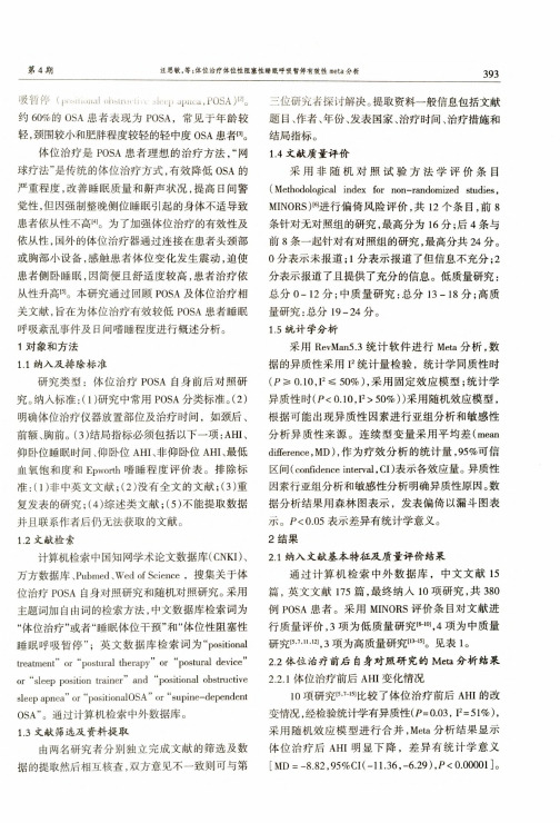
采用RevMan5.3统计软件进行Meta分析,数 据的异质性采用F统计量检验,统计学同质性时 (PM CIO# W 50%),采用固定效应模型;统计学 异质性时(P<0.10,l2>50%))采用随机效应模型, 根据可能出现异质性因素进行亚组分析和敏感性 分析异质性来源。连续型变量采用平均差(mean difference, MD),作为疗效分析的统计量,95%可信 区间(confidence interval,CI)表示各效应量。异质性 因素行亚组分析和敏感性分析明确异质性原因。数 据分析结果用森林图表示,发表偏倚以漏斗图表 示。P<0.05表示差异有统计学意义。 2结果 2.1纳入文献基本特征及质量评价结果
研究类型:体位治疗POSA自身前后对照研 究。纳入标准:(1)研究中常用POSA分类标准o(2) 明确体位治疗仪器放置部位及治疗时间,如颈后、 前额、胸前。(3)结局指标必须包括以下一项:AHI、 仰卧位睡眠时间、仰卧位AHI、非仰卧位AHI、最低 血氧饱和度和Epworth嗜睡程度评价表。排除标 准:(1)非中英文文献;(2)没有全文的文献;(3)重 复发表的研究;(4)综述类文献;(5)不能提取数据 并且联系作者后仍无法获取的文献。 1.2文献检索
or **sleep position trainer" and ** positional obstructive sleep apnea" or "positionalOSA" or ** supine-dependent 0SA"o通过计算机检索中外数据库。 1.3文献筛选及资料提取
STF202-22T1G;STF202-22T1;中文规格书,Datasheet资料
SCANNER PRINTER
HUB
MONITOR
COMPUTER PC CPU
KEYBOARD
TELEPHONE PLOTTER MOUSE
Figure 5. Typical USB System
Typically the USB system consists of one host, hubs and devices.
Typical Applications:
• USB Hubs • Computer Peripherals Using USB
MAXIMUM RATINGS (TA = 25°C)
Rating
Symbol
Value
Unit
Steady State Power
PD
225
mW
Maximum Junction Temperature TJ(max)
Pull−up Resistor Rup (kW)
Min Nom Max 1.35 1.5 1.65
TYPICAL CHARACTERISTICS
(d−20
Vdc = 0 V
−30 −40
−50
−60
−70
−80 −90
0.1
1
10
(MHz)
100
1000
Figure 1. Analog Cross−talk (D+ to D−)
21.2
21.0 −30 −20 −10
0 10 20 30 40 50 60 70 80 TEMPERATURE (°C)
Figure 3. RS versus Temperature
Rup (Ohms)
1540 1530 1520 1510 1500 1490 1480 1470 1460 1450
国内外常用材料钢号、化学成分、机械性能对照表
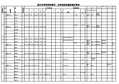
日 JIS 本 JIS
0.035 410 (42) 0.035 415 (42) 0.025 ≤0.40 0.025 ≤0.40 ≤0.40 ≤0.40 ≤0.15 ≤0.15 485 410-530 440-640 (4565) 440-640 (4565) 440-640 (4565) 410 (42) 275
焊丝钢号 焊丝钢号
牌号
中国 GB700-88 日本 美国 德国 中国 GB700-88 日本 美国 德国 中国 中国 中国 GB1519-88 日本 德国 中国 GB1519-88 日本 日本 美国 中国 GB3077-88 日本 美国 中国 日本 美国
0.14~ 0.22 ≤0.30
0.12~ 0.20 ≤0.30
钢 (二
20
0.10~ 0.35 0.30~ 1.00 ≥0.10 ≥0.10 0.29~ 1.06 0.29~ 1.06
ASTM A106-95a B
素
美 国 ASTM A106-95a C
德 国 DIN 17175-79 ST45.8 -Ⅲ 15CrMo 15CrMo 15CrMo STFA22 STPA22 STBA22
中 GB 6479-86 国 GB 9948-88
JIS G3462-88 G3467-88 G3458-88
410 (42)
日 JIS 本 JIS 1 Cr ~ 1/2 Mo
0.45~ 0.65 410 (42) 0.45~ 0.65 0.44~ 0.65 0.44~ 0.65 0.45~ 0.65 415 (42) 415 (42) 440-590 (4560)
H08AGB 6479-86
JIS G3456-88 G3461-88 G3467-88
Thermo Form 311 CO2培养箱中文说明书

型号310系列二氧化碳培养箱操作及维护指南手册号:7010310 第一版所有型号参阅第i页手册号 7010310- 22434/IN-3211 8/25/04 更新增湿盘水质量描述 CCS1 21730/SI-9181 6/16/04 添加可调换的250085底座 CCS0 22078/IN-3180 3/16/04 原始手册-将156098型号的风机发动机更新为156126型号。
CCSREV ECR/ECN DATE DESCRIPTION By仔细阅读本指南如未阅读,理解,遵循本指南将导致设备受损,人员受到伤害和设备的低效运行。
注意:所有的调节和维修工作必须由合格的专业人员操作。
参见本手册后的型号标签*T/C是热导传感器IR是红外传感器**所有单位是50/60HZ内部材料为铜产品性能可能发生变化。
热电公司对该指南本身不作保证。
如因使用指南不当或与指南相关的问题造成直接或偶然的损失,本公司不负有任何责任。
如不按照操作指南进行操作,该设备所设计的保护将遭到破警告:设备和配件很容易因其释放的静电(ESD)而受损重要的操作和维护说明,请仔细阅读所附正文。
感叹号后边那部分是法语,我翻不了……用电的潜在危险,只有合格的工作人员才能进行操作。
感叹号后边那部分是法语,我翻不了……√使用适当的保护设备(工作服,手套,护目镜等等)√避免空气过热或过冷,并且需穿防护衣。
√有良好的卫生习惯。
√每个工作人员都要对自己的安全负责。
关于热电集团的产品,您是否需要更多的信息或者帮助?如果需要,请按以下方式在8:00到18:00(东部时间)联系我们:直拨:1-740-373-4763免费电话(美国和加拿大):1-888-213-1790传真:1-740-373-4189网址:服务邮箱地址:services.controlenvce.@我们的销售人员可为您提供价格信息和报价表。
我们可按照订单为您提供主要的仪器交付条款信息或安排当地的销售代表联系您。
HFM202资料

VOLTAGE RANGE 50 to 1000 Volts CURRENT 2.0 AmperesELECTRICAL CHARACTERISTICS (At T A = 25o C unless otherwise noted)MAXIMUM RATINGS (At T A = 25o C unless otherwise noted)HIGH EFFICIENCY SILICON RECTIFIERNOTES : 1. Test Conditions: I F =0.5A, I R =-1.0A, I RR =-0.25A.2. Measured at 1 MH Z and applied reverse voltage of 4.0 volts.2001-5RATINGSMaximum Recurrent Peak Reverse Voltage Maximum RMS VoltsMaximum DC Blocking Voltage Maximum Average Forward Current at T A = 50o CPeak Forward Surge Current 8.3 ms single half sine-wave superimposed on rated load (JEDEC method)Typical Junction Capacitance (Note 2)Operating and Storage Temperature RangeSYMBOL V RRM V DC I O I FSM C J T J , T STGV RMS Volts Volts Volts Amps 2.06030-65 to + 175Amps pFCUNITS 20Maximum DC Reverse Current at CHARACTERISTICSV F SYMBOL I R trrUNITS uAmps nSec Maximum Full Load Reverse Current, Full cycle Average T A = 55oC Maximum Forward Voltage at 2.0A DCVolts 5.050Maximum Reverse Recovery Time (Note 1)Rated DC Blocking Voltage HFM201HFM206HFM203HFM207HFM208HFM20450uAmps 1.01.775HFM 201503550HFM 20210070100HFM 204300210300HFM 205400280400HFM 207800560800HFM 20810007001000HFM 203200140200HFM 206600420600HFM202HFM2051.3@T A = 25o C @T A = 125o C 100uAmpsRATING AND CHARACTERISTIC CURVES ( HFM201 THRU HFM208 )FIG. 1 - TEST CIRCUIT DIAGRAM AND REVERSE RECOVERY TIME CHARACTERISTIC50102. Rise Time = 10ns max. Source Impedance = 50 ohms.0-1.0A10/20 ns/cmFIG. 2 - TYPICAL FORWARD CURRENT DERATING CURVE A V E R A G E F O R W A R D C U R E N T , (A )AMBIENT TEMPERATURE ( )4.02.00255075100125150175Single Phase Half Wave 60Hz Resistive or Inductive LoadFIG. 6 - TYPICAL JUNCTION CAPACITANCEJ U N C T I O N C A P A C I T A N C E , (p F )REVERSE VOLTAGE, ( V )604020106421.1.2.41.024*********FIG. 3 - TYPICAL REVERSE CHARACTERISTICSI N S T A N T A N E O U S R E V E R S E C U R R E N T , (u A )PERCENT OF RATED PEAK REVERSE VOLTAGE, (%)100101.0.1.01FIG. 5 - MAXIMUM NON-REPETITIVE FORWARD SURGE CURRENTP E A K F O R W A R D S U R G E C U R R E N T , (A )NUMBER OF CYCLES AT 60Hz7060504030201001251020501008.3ms Single Half Sine-Wave (JEDEC Method )FIG. 4 - TYPICAL INSTANTANEOUS I N S T A N T A N E O U S F O R W A R D C U R R E N T , (A )INSTANTANEOUS FORWARD VOLTAGE, (V)101.0.1.01.001.2.4.6.8 1.0 1.2 1.4 1.6 1.8。
STTH2002资料

May 2006 Rev 11/10STTH2002Ultrafast recovery diodeMain product characteristicsFeatures and benefits■Ultrafast switching ■Low reverse current ■Low thermal resistance■Reduces switching and conduction losses ■High T j■Insulating voltage: 2500 V rms ■Capacitance: 7 pFDescriptionSingle rectifier suited for switch mode power supply and high frequency DC to DC converter. Packaged in D²P AK, TO-220AC and insulated TO-220AC, this device is intended for low voltage, high frequency inverters, free wheeling and polarity protection applicationsOrder codesI F(AV)20 A V RRM 200 V T j (max)175° C V F (typ)0.86 V t rr (typ)16 nsPart Number Marking STTH2002D STTH2002STTH2002DI STTH2002STTH2002G STTH2002STTH2002G-TRSTTH2002Characteristics STTH20022/101 CharacteristicsTo evaluate the conduction losses use the following equation: P = 0.75 x I F(AV) + 0.01 I F 2(RMS)Table 1.Absolute ratings (limiting values at T j = 25° C, unless otherwise specified)Symbol ParameterValue Unit V RRM Repetitive peak reverse voltage 200V I F(RMS)RMS forward current35A I F(AV)Average forward current, δ = 0.5TO-220AC, D 2P AK T c = 120° C 20A TO-220ACins T c = 60° CI FSM Surge non repetitive forward current t p = 10 ms Sinusoidal175A T stg Storage temperature range-65 to + 175° C T jMaximum operating junction temperature175° CTable 2.Thermal parametersSymbol ParameterValue Unit R th(j-c)Junction to caseTO-220AC, D 2P AK 2.4° C/WTO-220ACins5Table 3.Static electrical characteristicsSymbol ParameterTest conditionsMin.TypMax.Unit I R (1)Reverse leakage currentT j = 25° C V R = V RRM10µAT j = 125° C 10100V F (2)Forward voltage dropT j = 25° C I F = 20 A1 1.1V T j = 150° C0.860.95T j = 25° C I F = 25 A1.15T j = 125° C 0.94 1.05T j = 150° C0.911.Pulse test: t p = 5 ms, δ < 2 %2.Pulse test: t p = 380 µs, δ < 2 %STTH2002Characteristics3/10Table 4.Dynamic characteristicsSymbolParameterTest conditionsMin.Typ Max.Unitt rrReverse recovery timeI F = 1 A, dI F /dt = -200 A/µs,V R = 30 V , T j = 25 °C 1620nsI F = 1 A, dI F /dt = -50 A/µs,V R = 30 V , T j = 25 °C 3340I RM Reverse recovery current I F = 20 A, dI F /dt = 100 A/µs,V R = 160 V , T j = 125 °C 810A t fr Forward recovery time I F = 20 A, dI F /dt = 100 A/µs V FR = 1.1 x V Fmax , T j = 25 °C 230ns V FPForward recovery voltageI F = 20 A, dI F /dt = 100 A/µs,V FR = 1.1 x V Fmax , T j = 25 °C2V Figure 1.Peak current versus duty cycle Figure 2.Forward voltage drop versusd Tδ=tp/T tpFigure 3.Forward voltage drop versusforward current (maximum values)Figure 4.Relative variation of thermal impedance, junction to case,CharacteristicsSTTH20024/10Figure 5.Junction capacitance versus reverse applied voltage (typicalFigure 6.Reverse recovery charges versus dI F /dt (typical values)Figure 7.Reverse recovery time versusFigure 8.Peak reverse recovery current Figure 9.Dynamic parameters versus junction temperatureFigure 10.Thermal resistance, junction toambient, versus copper surface under tab (Epoxy printed circuit2STTH2002Ordering information scheme 2 Ordering information scheme5/10Package information STTH20026/103 Package informationEpoxy meets UL94, V0Cooling method: by conduction (C)Recommended torque value: 0.8 Nm Maximum torque value: 1.0 NmSTTH2002Package information7/10Package information STTH20028/102In order to meet environmental requirements, ST offers these devices in ECOP ACK® packages. These packages have a lead-free second level interconnect. The category of second level interconnect is marked on the package and on the inner box label, in compliance with JEDEC Standard JESD97. The maximum ratings related to soldering conditions are also marked on the inner box label. ECOP ACK is an ST trademark. ECOP ACK specifications are available at: .2STTH2002Ordering information9/104 Ordering information5 Revision historyPart Number Marking Package Weight Base qtyDelivery modeSTTH2002D STTH2002TO-220AC 1.90 g 50Tube STTH2002DI STTH2002TO-220ACins 2.30 g 50Tube STTH2002G STTH2002D 2P AK 1.48 g 50Tube STTH2002G-TRSTTH2002D 2P AK1.48 g1000Tape and reelDate RevisionDescription of Changes03-May-20061First issueSTTH200210/10Please Read Carefully:Information in this document is provided solely in connection with ST products. STMicroelectronics NV and its subsidiaries (“ST”) reserve the right to make changes, corrections, modifications or improvements, to this document, and the products and services described herein at anytime, without notice.All ST products are sold pursuant to ST’s terms and conditions of sale.Purchasers are solely responsible for the choice, selection and use of the ST products and services described herein, and ST assumes no liability whatsoever relating to the choice, selection or use of the ST products and services described herein.No license, express or implied, by estoppel or otherwise, to any intellectual property rights is granted under this document. If any part of this document refers to any third party products or services it shall not be deemed a license grant by ST for the use of such third party products or services, or any intellectual property contained therein or considered as a warranty covering the use in any manner whatsoever of such third party products or services or any intellectual property contained therein.UNLESS OTHERWISE SET FORTH IN ST’S TERMS AND CONDITIONS OF SALE ST DISCLAIMS ANY EXPRESS OR IMPLIED WARRANTY WITH RESPECT TO THE USE AND/OR SALE OF ST PRODUCTS INCLUDING WITHOUT LIMITATION IMPLIED WARRANTIES OF MERCHANTABILITY, FITNESS FOR A PARTICULAR PURPOSE (AND THEIR EQUIVALENTS UNDER THE LAWS OF ANY JURISDICTION), OR INFRINGEMENT OF ANY PATENT, COPYRIGHT OR OTHER INTELLECTUAL PROPERTY RIGHT. UNLESS EXPRESSLY APPROVED IN WRITING BY AN AUTHORIZE REPRESENTATIVE OF ST, ST PRODUCTS ARE NOT DESIGNED, AUTHORIZED OR WARRANTED FOR USE IN MILITARY, AIR CRAFT, SPACE, LIFE SAVING, OR LIFE SUSTAINING APPLICATIONS, NOR IN PRODUCTS OR SYSTEMS, WHERE FAILURE OR MALFUNCTION MAY RESULT IN PERSONAL INJURY, DEATH, ORSEVERE PROPERTY OR ENVIRONMENTAL DAMAGE.Resale of ST products with provisions different from the statements and/or technical features set forth in this document shall immediately void any warranty granted by ST for the ST product or service described herein and shall not create or extend in any manner whatsoever, anyliability of ST.ST and the ST logo are trademarks or registered trademarks of ST in various countries.Information in this document supersedes and replaces all information previously supplied.The ST logo is a registered trademark of STMicroelectronics. All other names are the property of their respective owners.© 2006 STMicroelectronics - All rights reservedSTMicroelectronics group of companiesAustralia - Belgium - Brazil - Canada - China - Czech Republic - Finland - France - Germany - Hong Kong - India - Israel - Italy - Japan - Malaysia - Malta - Morocco - Singapore - Spain - Sweden - Switzerland - United Kingdom - United States of America。
ENPI 202 series(with 205 206) 技术资料 2008-9-1-

EVERLIGHT GROUP
Confidential
13
S tr ip p a b il ity
Condition
Substrate Softbake Thickness Exposure PEB Development Rinse Stripper GaAs 90 60sec. (hotplate)
4
S p in C u r v e
170000 160000 150000 140000 130000 120000
ENPI 202 103cP ENPI 205 230cP ENPI 206 807cP
Thickness (A)
110000 100000 90000 80000 70000 60000 50000 40000 30000 20000 10000 0 1000 2000 3000 4000 5000 6000 7000
Spin speed (rpm)
EVERLIGHT GROUP
Confidential
5
E x p o s u r e V s . P r o fil e O v e r h a n g
Condition
Substrate Softbake Thickness Exposure PEB Development Rinse
10 um L/S
70mJ/cm2
90mJ/cm2
110mJ/cm2
130mJ/cm2
70mJ/cm2
90mJ/cm2
110mJ/cm2
130mJ/cm2
EVERLIGHT GROUP
Confidential
11
E x p o s u r e V s . P r o fil e O v e r h a n g
多相剪切增稠液的流变性能
多相剪切增稠液的流变性能田明月; 孙润军; 王蕊宁; 王秋实; 陈美玉【期刊名称】《《纺织高校基础科学学报》》【年(卷),期】2019(032)003【总页数】6页(P264-269)【关键词】剪切增稠液; 分散相; 碳化硅; 流变性能【作者】田明月; 孙润军; 王蕊宁; 王秋实; 陈美玉【作者单位】西安工程大学纺织科学与工程学院陕西西安 710048【正文语种】中文【中图分类】O6480 引言剪切增稠液(STF)是一种胶质悬浮液的非牛顿可逆流体, 当剪切速率或剪切应力发生变化时,其黏度就会随之发生变化,且随剪切速率的增加而增加[1]。
具有这种现象的流体因为粒子团聚等缺陷会破坏生产设备、阻碍输送管道等,给生产造成不利影响[2]。
STFs的这种特性,在防刺领域具有广泛的应用前景。
近年来关于单分散相剪切增稠液的研究较多, 对于多相剪切增稠液的研究主要集中于防弹衣的抗冲击性能、工业设备的减振性能等方面。
多相剪切增稠液(STFs)具有广阔的应用范围,比如摩托车头盔、运动防护眼镜、防刺服等[3-4]。
为了使防刺复合材料的性能更加优异,与高性能纤维织物复合的多相剪切增稠液(STFs)需要具备良好的增稠效果。
影响STFs流变行为的因素很多,如粒径、颗粒硬度、粒径比、分散介质、温度等[5],SiC颗粒粒径较小、硬度很大,所以常选取SiC 作为第二分散相[6-7]。
为了探索第二分散相SiC的加入对剪切增稠液流变性能的影响规律,为STFs的应用提供新的经验, 文中采用PEG200与SiO2制备单相剪切增稠液,再加入不同质量分数的SiC进行复配,制备多相剪切增稠液,并研究其稳态与动态流变性能,为后期浸渍高性能纤维织物,制备具有较好防刺性能并且舒适、轻便的防刺服装提供参考。
1 实验1.1 材料与仪器1.1.1 材料气相二氧化硅(SiO2,粒径50 nm,比表面积150 m2/g,阿拉丁工业公司),碳化硅(SiC,粒径50 nm,上海巷田纳米材料有限公司),聚乙二醇(PEG200,分散介质,平均分子量200,天津市科密欧化学试剂有限公司),无水乙醇等(天津市富宇精细化工有限公司)。
基于AT89C52单片机为核心的火灾报警器的研制

第26卷第5期 电 站 系 统 工 程 V ol.26 No.52010年9月Power System Engineering 71文章编号:1005-006X(2010)05-0071-02基于AT89C52单片机为核心的火灾报警器的研制Research of Fire Alarm System Based on AT89C52 Microcomputer哈尔滨电站工程有限责任公司 单晓亮1 系统原理及功能1.1 火灾探测原理火灾探测能力是火灾信号强度和传感器灵敏度的函数。
本文采用高灵敏度的温度传感器与气体传感器作为探测器,报警系统将传感器输出的电信号经滤波放大处理后送入A/D 转换器,得到的数字信号由单片机进行处理分析,当程序判断存在火灾危险时启动声光报警及自动消防设备[1]。
1.2 系统功能本文研制的火灾自动报警系统主要包括火灾探测器、报警控制器及自动消防设备等部分。
火灾报警器主要实现以下功能:利用烟雾传感器和温度传感器对室内烟雾及温度突变进行报警,能进行区域报警;上述两种传感器中一种动作,表明有异常现象,发异常报警信号;如同时动作说明有火灾,发火灾报警;火灾报警10 s 内不解除,发出灭火信号,启动自动消防设备;故障、异常、火灾报警声音各不相同,有明显区别,且各自有相应的指示灯,便于值班人员分辨情况及时处理。
2 报警器硬件设计如图1所示,报警器硬件主要由温度烟雾信号采集模块、微处理器单元、键盘输入单元、LED 显示单元、实时时钟模块、看门狗复位电路、声光报警模块、自动消防设备图1 系统的硬件组成2.1 温度烟雾信号采集模块温度检测选用美国Analog Devices 公司生产AD590芯片,它是一种电流型二端温度传感器,其输出同绝对温度成正比,由于A/D 转换芯片的输入要求是电压量,因此在AD590的负极接出一个10 k 的电阻串连一个可调电阻,将电流量变为电压量送入模数转换器。
实际应用中,通过改编可调电阻的阻值,便可在输出端获得与绝对温度成正比的电收稿日期:2010-05-18单晓亮(1979-),男,工程师。
- 1、下载文档前请自行甄别文档内容的完整性,平台不提供额外的编辑、内容补充、找答案等附加服务。
- 2、"仅部分预览"的文档,不可在线预览部分如存在完整性等问题,可反馈申请退款(可完整预览的文档不适用该条件!)。
- 3、如文档侵犯您的权益,请联系客服反馈,我们会尽快为您处理(人工客服工作时间:9:00-18:30)。
Pull–up Resistor Rup (kW)
Min Nom Max 1.35 1.5 1.65
TYPICAL CHARACTERISTICS
(dB)
10
0
–10
P = –25 dBm
–20
Vdc = 0 V
–30 –40
–50
–60
–70
–80 –90
0.1
1
10
(MHz)
100
1000
Figure 1. Analog Cross–talk (D+ to D–)
元器件交易网
STF202-22
USB Filter with ESD Protection
This device is designed for applications requiring Line Termination, EMI Filtering and ESD Protection. It is intended for use in upstream USB ports, Cellular phones, Wireless equipment and computer applications. This device offers an integrated solution in a small package (TSOP–6, Case 318G) reducing PCB space and cost.
• Bi–directional EMI Filtering Prevents Noise from Entering/Leaving
the System
• IEC61000–4–2 ESD Protection for USB Port • Flexible Pull–down or Pull–up Line Termination to Meet USB 1.1
Typical Applications:
• USB Hubs • Computer Peripherals Using USB
MAXIMUM RATINGS (TA = 25°C)
Rating
Symbol
Value
Unit
Steady State Power
PD
225
mW
Maximum Junction Temperature TJ(max)
Low Speed and High Speed Specification
• ESD Ratings: Machine Model = C
ESD Ratings: Human Body Model = 3B
Benefits:
• TSOP–6 Package Minimizes PCB Space • Integrated Circuit Increases System Reliability versus Discrete
21.2
21.0 –30 –20 –10
0 10 20 30 40 50 60 70 80 TEMPERATURE (°C)
Figure 3. RS versus Temperature
Rup (Ohms)
1540 1530 1520
TARGET
1510
1500
1490
1480
1470
1460
1450 –30 –20 –10
0 10 20 30 40 50 60 70 80 TEMPERATURE (°C)
Figure 4. Rup versus Temperature
2
元器件交易网
STF202–22
APPLICATIONS BACKGROUND
What Is USB? The USB is not a serial port, it is a serial bus, a fact that
D
= Date Code
ORDERING INFORMATION
Device
Package
Shipping
STF202–22T1 TSOP–6 3000/Tape & Reel
© Semiconductor Components Industries, LLC, 2002
1
July, 2002 – Rev. 6
The Universal Serial Bus (USB) makes connecting devices to your computer faster, easier and virtually limitless. High–Speed USB devices are capable of communicating at speeds up to 12 megabits without shutting down and without having to open your computer.
Features:
• Provides USB Line Termination, Filtering and ESD Protection • Single IC Offers Cost Savings by Replacing 3 Resistors,
2 Capacitors, and 5 TVs diodes
Publication Order Number: STF202–22T1/D
元器件交易网
STF202–22
ELECTRICAL CHARACTERISTICS (TA = 25°C)
Device
Device VRWM Marking (Volts)
VBR @ 1 mA (Volts)
STF202–22T1 S22
5.25 6.0 8.01. For other RS values (i.e. RS = 30 W) contact your local ON Semiconductor sales representative. 2. Measured at 25°C, VR = 0 V, f = 1 MHz, Pins 2, 3, 4 or 5 to GND with Pin 1 also grounded. 3. For other capacitance values contact your local ON Semiconductor sales representative.
SCANNER PRINTER
HUB
MONITOR
COMPUTER PC CPU
KEYBOARD
TELEPHONE PLOTTER MOUSE
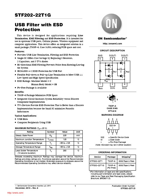
Figure 5. Typical USB System
Typically the USB system consists of one host, hubs and devices.
125
°C
Operating Temperature Range
TJ
–55 to +125
°C
Storage Temperature Range
Tstg
–55 to +125
°C
Lead Solder Temperature (10 second duration)
TL
260
°C
(dB)
50
40
30
P = –25 dBm
20
Vdc = 0 V
10 0
–10
–20
–30
–40 –50
0.1
1
10
(MHz)
100
1000
Figure 2. Insertion Loss Characteristics
RS (Ohms)
22.2 22.0
RS– TARGET
21.8
21.6
21.4
The Hub provides an interconnect point, which enables many devices to connect to a single USB port. The logical topology of the USB is a star structure, all the devices are connected (logically) directly to the host. It is totally transparent to the device what is its hub tier (the number of hubs the data has to flow through). The hub is connected to the USB host in the upstream direction (data flows “up” to the host) and is connected to the USB device in the downstream direction (data flows “down” from the host to the device). The hub’s main functionality is the responsibility of detecting an attachment and detachment of devices, handling the power management for devices that are bus–powered (get power from the bus), and responsibility for bus error detection and recovery. Another important role of the hub is to manage both full and low speed devices. When a device is attached to the system the hub detects the speed, which the device operates in, and through the whole communication on the bus prevents from full speed traffic to reach low speed device and vice versa – prevent from low speed traffic to reach full speed device.
