信翼说明书D921
ASM AD9212作业指导书

关键词:定期点检预防保养特殊特性:无1. 目的:通过对设备全面检查和维护,全面了解设备的性能和状态,使设备的使用寿命得到有效的管控,确保设备的状态与性能的完好,延长设备的有效使用寿命。
2.适用范围:本作业指导书适用于ASM AD9212装片机的定期点检、周期性预防保养。
3.周期:3.1设备定期点检周期为12个月。
3.2设备保养周期见《ASM AD9212保养作业方法及判定内容表》。
4.职责:设备的预防保养、定期点检由本工序设备担当人员实施,产品品质由MC人员确认。
5.注意事项:5.1实施人员必须依照文件来点检和保养设备,并如实填写“点检成绩书。
5.2特别要注意:在可能有制品通过的位置进行保养、点检时,要注意备件的紧固、油量的控制等细节问题,不能留有潜在的危险和隐患。
ASM AD9212装片机定期点检判定内容表表1:ASM AD9212定期点检成绩书ASM AD9212保养作业方法及判定内容表表2:ASM AD9212保养成绩书机号:设备编号:设备类型:计划保养日期:表格编号:FCDB13-016A表3:ASM AD9212月保养成绩书机号:设备编号:设备类型:表格编号:FCDB13-017A工作台--------模组绝缘1)进入菜单setup→workholder→off 关闭马达2)进入菜单setup→workholder→MA1(or)MA2→vacuum附录:清理润滑位置和方法1. 清洁光敏传感器(每季)步骤:1)按照之前提示使工作台绝缘2)定位所有光敏传感器3)用真空吸尘器清洁光敏传感器4)通过遮挡与不遮挡传感器检查 service→motion diagnostic→workholder→motor(select target channel)→motor test菜单下的传感器状态2润滑LM导轨(每半年)步骤:1)按照之前提示使工作台绝缘2)手推动工作台,用无尘布擦去LM导轨上所有旧的润滑油3)将LM滑块的注油嘴或滑块定位于适当位置,如下图4)用带适当注油嘴的注油枪对LM导轨滑块注油孔施加适当的THK AFB润滑脂5)手动使工作台从一端移动到另一端4-5次使润滑脂均匀分布在导轨上6)用无尘布擦除LM导轨上多余的润滑脂名称FC ASM AD9212 PM 作业指导书3 清洁砧座(每日)步骤:1)按照之前提示使工作台绝缘2)用无尘布沾酒精擦除砧座表面的污染物名称FC ASM AD9212 PM 作业指导书4 清洁线性马达及磁石板(按需要)步骤:1)按照之前提示使工作台绝缘2)将各功能组件移到一侧3)若线性马达磁表面有障碍物存在,应利用胶布清楚,若有油污存在应用无尘布清洁4)重复步骤2-3清洁线性马达另一侧5 清洁线性编码器(每季)步骤:1)按照之前提示使工作台绝缘2)定位线性马达编码器位置3)拆除编码器,用沾有异丙烷或正庚烷的无尘布清洁光尺与读取头(切勿使用丙酮进行清洗)4)完成清洁后装回编码器并调节位置使整个行程一直亮绿灯及回到参考标识位置时红灯闪烁名称FC ASM AD9212 PM 作业指导书6.润滑LM导轨和引导丝杆与圆锥齿轮及蝸轮蜗杆(每半年)步骤:1)按照之前提示使工作台绝缘2)旋转传动轴使工作台移至适当位置3)用无尘布擦去LM导轨和引导丝杆与圆锥齿轮及蝸轮蜗杆上所有旧的润滑脂4)用注油枪手动对LM导轨滑块注油孔施加适量的THK AFB润滑脂;用加油匙手动对引导丝杆施加适当的NSK PS2润滑脂;用加油匙手动对圆锥齿轮表面施加适量的NSK PS2润滑脂;用加油匙手动对蜗轮蜗杆表面施加适当的NSK PS2润滑脂5)旋转传动轴使LM导轨和引导丝杆从一端移到另一端4-5次/使圆锥齿轮转4-5圈使油脂均匀分布在LM导轨和引导四缸与圆锥齿轮及窝轮蜗杆上6)用无尘布擦除LM导轨和引导丝杠与圆锥齿轮及蜗轮蜗杆上多余的润滑脂名称FC ASM AD9212 PM 作业指导书7 润滑LM导轨和凸轮(每半年)步骤:1)按照之前提示使工作台绝缘2)旋转传动轴使凸轮和LM导轨滑块移至适当位置3)用无尘布擦去LM导轨和凸轮上所有旧的润滑脂4)用注油手枪对LM导轨滑块注油孔施加适量的THK AFB润滑脂;用加油匙手动对凸轮表面施加适当的NSK PS2润滑脂5)旋转传动轴使LM导轨从一端移到另一端4-5次,使润滑脂均匀分布在LM导轨和凸轮上6)用无尘布擦除LM导轨和凸轮上多余的润滑脂名称FC ASM AD9212 PM 作业指导书8 检查皮带步骤:1)按照之前提示使工作台绝缘2)定位工作台上的皮带,如图1和图23)手动旋转皮带目视检查皮带的位置与状态4)用张力计检查皮带频率是否位于数值范围内。
欧洲之星私密仪器中文说明书
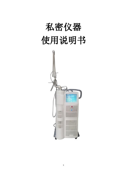
私密仪器使用说明书目录目录 (3)安全指导 (4)前言 (5)操作说明 (6)1系统操作原理 (6)1.1 CO2激光治疗仪原理 (6)1.2 私密治疗原理 (6)1.3 治疗范围 (7)1.4 产品优势 (7)1.5 仪器描述 (7)1.6 主要组成部分 (7)2 开机准备 (9)2.1 拆包装检查 (9)2.2 连接关节臂 (9)2.3 加冷却液 (9)2.4 检查输入电压 (9)2.5 连接电源线 (9)2.6 连接脚踏开关 (10)2.7 试运行 (10)3 操作方法 (10)3.1 开机界面 (10)3.2 功能选择界面: (10)3.3 美肤模式界面: (11)3.4 普通模式界面: (13)3.5 私密模式界面: (15)3.5设置界面 (17)3.6保护界面 (17)4 指示光 (19)5 注意事项 (19)6 维护保养 (20)6.1 镜头清洁 (20)6.2 机箱清洁 (20)6.3 功率校准 (20)6.4 保险丝更换 (20)6.5刀头消毒 (20)7 随机附件 (20)8 故障排除 (21)9 技术参数 (22)10 质量保证及售后服务 (23)11 系统内部结构图 (24)保修证 (25)安全指导以下信息包括了本产品设计与生产所参照的技术规范以及操作注意事项,为仪器的正确使用提供安全指导。
点阵激光系统的设计与生产遵照了以下3个领域的安全规范:1. 电气安全规范2. 激光辐射安全规范3. 电磁辐射安全规范以上规范所参照的技术标准由国际电工委员会(IEC)制定,标准如下:IEC 60601-1Medical electric equipment part 1: General requirements for safetyIEC 60601-1-2Medical electric equipment general requirement for safety collateral standard: electromagnetic compatibility requirement and testIEC 60601-1-4Medical electric equipment general requirement for safety collateral standard: programmable medical electric equipmentIEC 60602-2-22Medical electric equipment part2, specific safety requirement on diagnosing and treatment laser equipmentIEC 60825-1Radiation safety for laser product, equipment classification requirement and user's guidance.激光系统有安全保护设计,但只有在正确的使用条件下才能确保安全。
WFT09(S)II 简易说明书 CN

1024/4096PCMS九通道2.4GHz遥控器感谢选用天地飞产品。
请在使用前详细阅读使用说明书,确保使用安全。
●售后服务●安全提示●产品配置如果您忽略此标志所指的操作说明,而做出错误的操作,有可能会造成使用者或他人死亡等严重危险伤害。
如果您忽略此标志所指的操作说明,而做出错误的操作,有可能会造成使用者或他人严重伤害或物品损坏。
如果您忽略此标志所指的操作说明,而做出错误的操作,有可能会造成使用者或他人的伤害或者物品损坏。
任何情况下都禁止尝试的操作。
任何情况下都请您务必遵守。
标志含义危险警告注意禁止务必遵守1.本使用说明书所记载的产品,在国内的无线电法令规定下,用途仅限于模型应用。
2.本产品在改装、调整、更换零件后,本公司将不负任何责任,敬请谅解。
本产品的用途、改装等注意事项1.WFLY 产品自购买之日起,属于质量问题一年内由深圳市天地飞科技开发有限公司免费保修(公司承担往返邮费)。
2.WFLY 产品自购买之日起七天内,在正常使用的情况下出现质量问题,外观无损坏,可凭保修卡及购机凭证在经销商处免费更换同型号产品;经销商收到更换产品时必须第一时间通知公司予以备案更换。
3.WFLY 产品将由深圳市天地飞科技开发有限公司提供终身售后服务;对于自购买之日起,人为损坏、改装、开盖损坏封条以及超过一年免费保修期的,用户必须支付往返邮费、材料成本费及维修成本费用。
4.为确保您的权益受到保护,并能及时有效的为您服务。
请在购买WFLY 产品时务必完整填写好保修卡及索要购机凭证;由销售商签字盖章。
用户享受本售后服务条款必须提供保修卡及购机凭证,缺一不可;销售商没有给消费者保修卡或不按要求填写的,由销售商承担全部的售后服务费用。
5.本售后服务条款仅限于中国大陆销售的WFLY 产品。
售后服务注意警告安全提示 (注意事项)在使用前请确认商品的配件是否都有备齐,接收机是否已经正常连接三线开关,舵机,遥控器与接收机是否都连接好了电源,以及确认是否都可开启并且有正确的动作后再使用。
Nordic Thingy 91产品简要说明版本1.4说明书

RGB LEDs
Temperature, humidity, air quality
and air pressure Light/color sensor
Buzzer
2.4 GHz antenna
Low-power accelerometer PMIC Battery connector Power switch
Nordic Thingy:91 Product Brief Verent Program/debug device
selection switch nRF9160 SiP
nRF52840 WLCSP
High-g accelerometer
Nano/4FF SIM card slot
An exhaustive set of sensors is included to gather data about the environment, and the movement of the Nordic Thingy:91. Temperature, humidity, air quality, air pressure, color and light data can easily be extracted for local or remote analysis.
and air pressure, plus a color and light sensor Low-power accelerometer and high-g accelerometer Buzzer 4 x N-MOS transistors for external DC motors or LEDs Rechargeable Li-Po battery with 1440 mAh capacity
System Sensor B112LP 插件探测器底座说明书

B112LP Plug-in Detector BaseFor use with the following smoke detectors:IN US: 1151, 2151IN CANADA: 1151A, 2151A IN EUROPE: 1151E, 2151EINSTALLATION AND MAINTENANCE INSTRUCTIONS3825 Ohio Avenue, St. Charles, Illinois 601741-800-SENSOR2, FAX: 630-377-6495Before InstallingPlease read thoroughly System Sensor’s Applications Guide for System Smoke Detectors (SPAG91), which provides detailed information on detector spacing, placement, zoning, wiring, and special applications. This manual is available online at . (For installa-tion in Canada, refer to CAN/ULC-S524, Standard for the Installation of Fire Alarm Systems and CEC Part 1, Sec. 32.)NOTICE: This manual should be left with the owner/user of this equipment.IMPORTANT: The detector used with this base must be tested and maintained regularly following NFPA 72 require-ments. The detector used with this base should be cleaned at least once a year.Specifications Base Diameter: 6.2 inches (157 mm)Base Height: 0.95 inches (24 mm)Weight: 0.3 lb. (137 g)Mounting: 4-inch square box with or without plaster ring. Min. depth–1.5 inches 3-1/2-inch octagon box. Min. depth–1.5 inches Operating T emperature Range: 0° to 49°C (32° to 120°F)Operating Humidity Range: 10% to 93% Relative Humidity, Noncondensing Electrical Ratings - includes base and detector System Voltage: 24 VDC Maximum Ripple Voltage: 4 Volts peak-to-peak Start-Up Capacitance: 0.02µF Maximum Standby Ratings: 20 VDC Minimum 29 VDC Maximum 120 µA Maximum Alarm Ratings: 17 mA Minimum 36 mA Maximum Reset Voltage: 1.4 VDC Minimum Reset Time: 0.3 Seconds Maximum (The optional RA400Z operates within specified detector alarm currents.)Start-up Time: 34.0 Seconds Maximum Relay Contact Ratings:Resistive or Inductive (60% Power Factor)Form A: 2.0 A @ 30 V AC/DC Form C: 2.0 A @ 30 V AC/DC 0.6 A @ 110 VDC 1.0 A @ 125 V AC General DescriptionThe Model B112LP detector base is designed for use with System Sensor model 2151 photoelectronic and 1151 ioniza-tion detector heads. This four-wire base is equipped with screw terminals for the connection of power, ground, and an optional remote annunciator.MountingThe detector base mounts directly to 3-1/2 inch and 4-inchoctagon boxes and 4-inch square boxes, with or without plaster rings. T o mount the base, remove the decorativering by rotating it in either direction to unhook the snapsbefore separating the ring from the base. Use the screws supplied with the junction box to attach the base to the box through the appropriate slots in the base (see Figure 1). Position the decorative ring around the base and rotateit in either direction until the ring snaps into place.I56-597-04RInstallation GuidelinesNOTE:Refer to the releasing device manufacturer’sinstructions for connection instructions. Allowable loop resistance is an important specification for control panels as well as for smoke detectors and their bases. The alarm system cannot be expected to operate correctly if system components have incompatible allow-able loop resistances. Therefore, before beginning installa-tion, refer to the control panel manufacturer’s loop resis-tance specification to ensure that it is listed as compatible with the System Sensor base and smoke detector being installed.All wiring must be installed in compliance with the National Electrical Code, all applicable local codes and any special requirements of the authority having jurisdiction, using the proper wire size. The conductors used to connect smoke detectors to control panels and accessory devices should be color-coded to reduce the likelihood of wiring errors. Improper connections can prevent a system from responding properly in the event of a fire.WiringFor signal wiring (the wiring between interconnected detectors), it is recommended that the wire be no smaller than A WG 18. However, the screws and clamping plate in the base can accommodate wire sizes up to A WG 12. The use of twisted pair wiring for the power (+ and -) loop is recommended to minimize the effects of electrical interfer-ence.NOTE: T o ensure that electrical connections are super-vised, DO NOT loop wires under terminals 2, 3,and 5 –break the wire at each terminal.T o make electrical connections, strip approximately 3/8” (1 cm) insulation from the end of each wire. Slide the wires under the clamp plate and tighten the terminal screw.If the base is being installed in a zoned system, check the zone wiring before installing the smoke detector head. The built-in shorting spring makes it convenient to do this. After the detector base is wired and attached to the electri-cal box, position the shorting spring against terminal 3. Use the slot in the retaining clip to hold the spring against the terminal, as shown in Figure 1. This shorts the negative-in and negative-out leads so that loop wiring can be tested for continuity.The shorting spring in the base will disengage automati-cally when the detector head is removed from the base. DO NOT remove the shorting spring since it reengages as the detector head is turned into the base, completing the circuit.RINGBASEBOXC0503-00 Figure 1. Mounting base to box:Tamper-resistance FeatureNOTE:DO NOT use the tamper-resistance feature if the System Sensor XR2 Removal T ool will be used toremove detectors from the base.This detector base can be made tamper resistant so the detector cannot be removed without the use of a tool. T o make the base tamper-resistant, break off the smaller tab at the scribed line on the tamper-resistance tab, on the detec-tor mounting bracket (see Figure 3A), before installing the detector.T o remove the detector from the base after it has been made tamper resistant, remove the decorative ring by rotating it in either direction and pulling it away from the base. Then, insert a small screwdriver into the notch, as indicated in figure 3B, and press the plastic lever toward the mounting surface before rotating the detector counterclockwise for removal.FCICONTROL PANELFIRST DETECTOR IN LOOP FIRST DETECTOR IN LOOPEOLRESISTORFigure 2. Typical wiring diagram:Figure 3A. Activating the tamper-resistance feature:USE SMALL-BLADED SCREWDRIVER TO PUSH PLASTIC LEVER IN DIRECTION OF ARROWFigure 3B. Removing detector head from base:C0130-00C0532-00THREE-YEAR LIMITED WARRANTYSystem Sensor warrants its enclosed smoke detector base to be free from defects in materials and workmanship under normal use and service for a period of three years from date of manufacture. System Sensor makes no other express warranty for this smoke detector base. No agent, represen-tative, dealer, or employee of the Company has the authority to increase or alter the obligations or limitations of this Warranty. The Company’s obligation of this Warranty shall be limited to the repair or replacement of any part of the smoke detector base which is found to be defective in materials or workmanship under normal use and service during the three year period commencing with the date of manufacture. After phon-ing System Sensor’s toll free number 800-SENSOR2 (736-7672) for a Return Authorization number, send defective units postage prepaid to: Honeywell, 12220 Rojas Drive, Suite 700, El Paso TX 79936, USA. Please include a note describing the malfunction and suspected cause of failure. The Company shall not be obligated to repair or replace units which are found to be defective because of damage, unreasonable use, modifica-tions, or alterations occurring after the date of manufacture. In no case shall the Company be liable for any consequential or incidental damages for breach of this or any other Warranty, expressed or implied whatsoever, even if the loss or damage is caused by the Company’s negligence or fault. Some states do not allow the exclusion or limitation of incidental or con-sequential damages, so the above limitation or exclusion may not apply to you. This Warranty gives you specific legal rights, and you may also have other rights which vary from state to state.Please refer to insert for the Limitations of Fire Alarm Systems。
PCS-921N 说明书

2.4G 数传电台用户手册(V1.1)说明书

2.4G数传电台用户手册非常感谢您购买我司产品。
2.4G数传电台是一款优秀的无线电数据链路通信系统,采用先进的SHTT数字跳频技术,专业、稳定、通用。
为了共同维护飞行安全,也为了您能更好地使用本系统,请务必仔细阅读本手册。
如果您在使用本系统过程中遇到任何问题,请查阅本手册相关条目或者访问思翼科技官方网站()上与本系统相关的专题页面。
您也可以直接电话咨询思翼科技售后服务热线(4008382918)或邮件询问技术支持邮箱(****************)。
目录1阅读提示 (1)1.1标识符号的含义 (1)1.2飞行安全 (1)1.3携带、保管、废弃的注意事项 (3)2产品介绍 (4)2.1开关、接口定义 (4)2.2技术参数 (5)2.3LED指示灯定义 (6)3使用前 (7)3.1正确放置设备天线 (7)3.2对频 (8)4固件与波特率切换 (9)5数据输出(连接地面站) (13)6关于保修 (14)1阅读提示1.1标识符号的含义本说明书中,如出现以下符号,表示这部分内容需要特别留意:危险若忽略此操作,会有很大概率对使用者或他人造成人身伤害警告若忽略此操作,有可能会对使用者或他人造成人身伤害注意若忽略此操作,有可能会对使用者或他人造成经济损失禁止事项必须执行注释1.2飞行安全数传电台系统为专业应用场景设计制造,需要操作人员具备一定的基本技能,请务必小心使用。
任何针对本产品的不安全、不负责任的操作都有可能造成产品损坏,引起使用者或他人的经济损失甚至人身伤害。
未成年人使用本产品时须有专业人士在场监督指导。
未经思翼科技允许,禁止擅自拆卸或改装本产品。
针对本产品的安全使用和维护方法,在本手册中均有列出。
请在使用前仔细阅读本手册,严格按照其指示操作并参考注意事项,以防因不当操作造成意外。
为了共同维护飞行安全并让您更好地发挥本产品的特性,请留意以下事项:禁止使用数传电台在人群密集的地方(广场、公园等),障碍物较多的地方(街道、停车场等),有强磁场或信号干扰源的地方(高压线、高铁沿线、雷达站等)或其他可能引起经济损失乃至人身伤害的区域操控飞行器。
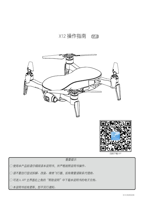
V1.0 X12 操作指南说明书
前位置悬停 5 秒钟,在此期间如未能重新连接通讯,飞行器即自动返航。 2) GPS 未定位状态时的失联保护功能
当飞行器未能 GPS 定位且与遥控器中断通讯约两秒后,飞行器将在当前位置自动降落。
7 校准指南针
注意:更换飞行场地后,务必在首次飞行前校准指南针。 使用过程中,如飞行器指示灯为“蓝绿灯交替闪烁”即表示指南针异常,需要校准指南针。 校准时请远离有磁场干扰的环境 , 否则会导致校准失败。
1
X12 操作指南
3 GPS 状态与飞行模式
本飞行器内置 GPS 定位模块,在自主飞行模式等功能时必须使用 GPS 设备进行定位。当飞行器 同时满足如下条件时,飞行器进入 GPS 定位模式: 1) 遥控器处于定点模式; 2) GPS 水平定位因子满足条件 ( 飞机状态指示灯为绿灯常亮 ) 时;
RCS-921A说明书
南瑞继保电气有限公司版权所有2003.10(V1.0X) 本说明书和产品今后可能会有小的改动,请注意核对实际产品与说明书的版本是否相符。
更多产品信息,请访问互联网:http://www.nari-relays.com 业务联系 电话:(025)83406078 83439746 传真:(025)83438965 技术支持 电话:(025)52100583 传真:(025)52100597 工程服务 电话:(025)52107703 传真:(025)52100770 质量保证 电话:(025)52100660 传真:(025)52100797 目录1 概述 (1)1.1应用范围 (1)1.2保护配置 (1)1.3保护配置性能特征 (1)2 技术参数 (2)2.1机械及环境参数 (2)2.2额定电气参数 (2)2.3主要技术指标 (2)3 软件工作原理 (4)3.1保护程序结构 (4)3.2正常运行程序 (4)3.3起动元件 (5)3.4断路器失灵保护 (6)3.5死区保护回路 (6)3.6瞬时跟跳回路 (7)3.7断路器三相不一致保护 (7)3.8充电保护 (7)3.9自动重合闸 (7)3.10保护与重合闸逻辑方框图 (10)4 硬件原理说明 (16)4.1装置整体结构 (16)4.2装置面板布置 (17)4.3装置接线端子 (17)4.4输出接点 (18)4.5结构与安装 (19)4.6各插件原理说明 (19)5 定值内容及整定说明 (30)5.1装置参数及整定说明 (30)5.2保护定值及整定说明 (31)5.3压板定值 (33)5.4IP地址 (33)- 1 -RCS-921A断路器失灵保护及自动重合闸装置 1 概述 1.1 应用范围 本装置适用于220KV及以上各种电压等级的211结线与角形结线的断路器。
1.2 保护配置 RCS-921A 是由微机实现的数字式断路器保护与自动重合闸装置, 装置功能包括断路器失灵保护、三相不一致保护、死区保护、充电保护和自动重合闸。
Extech 品牌 0.12英寸双射线热传感器说明书

Ordering42509.......................12"Distance Dual Laser InfraRed Thermometer 42509-NIST .............42509with NIST Certificate42509IR Thermometer with Color AlertProgrammable alarm with fast two-color display and audible alarm42512Dual Laser IR ThermometerFast and accurate measurements to 1832°F (1000°C)Features:•Great for processes that require temperature control and monitoring•Fast,accurate measurements at 12"where the two lasers converge with 12:1field of view •Measures up to 950°F (510°C)•Blue backlit dual LCD display changes to Red when reading exceeds High or Low set points•Exclusive 150millisecond instantaneous response for capturing spikes in temperature •Max mode captures and holds rapidly changing temperatures•Lock function for continuous readings •Adjustable emissivity increases measurement accuracy for different surfaces•Adjustable High/Low set points with audible alarm alerts user when temperature exceeds the programmed set points •Double molded housing•Complete with case and 9V batteryFeatures:•Dual laser simplifies distance-to-target ratio—no more calculations!•Accurate measurements at 30"distance •Exclusive 150millisecond instantaneous response for capturing spikes in temperature •Max mode captures andholds rapidly changing temperatures•Lock functionfor continuous readings •White backlit dual LCD display•Adjustable emissivity increases measurement accuracy for different surfaces •Double molded housing•Adjustable High/Low set points with audible alarm alerts user when temperature exceeds the programmed set points•Complete with carrying case and 9V battery30"Distance IRFastresponse captureshot spotsuseConvergence point 1"(2.54cm)spot30"(76.2c m)Ordering42512.......................30"Distance Dual Laser InfraRed Thermometer 42512-NIST .............42512with NIST CertificateBlue backlight:42570High Temperature IR Thermometer Fast response(100mS)with highest accuracy at point wheredual lasers converge plus Type K input and USB interfaceFeatures:•High50:1distance to target ratio measures smaller surface areas at greater distances•Dual Laser Targeting indicates ideal measuring distance when two laser points converge to1" target spot•Fast0.10second response time •Lock function for continuous measurements•Stores up to100readings •White backlit LCD with bargraph •MAX/MIN/AVG/DIF functions •Adjustable emissivity •Adjustable High/Low set points with audible alarm •T ripod mounting feature •Complete with Type K bead wire probe(-22to572°F/ -30to300°C),USB cable and PC software,tripod,9V battery and case(See pages42and80for Type K Thermocouple probes)Type K input42560IR Thermometer with Wireless PC InterfaceWireless USB interface transmits temperature data to a PCFeatures:•Place meter on the Base totransmit wirelessly continuousreadings to the Remote Receiverconnected to a PC via USB cable•High30:1distance to target ratio•Built-in laser pointer•Lock function for continuousmeasurements•Stores up to20readings•Type K temperature function•MAX/MIN/AVG/DIF functions•Manual/Automatic emissivity•High/Low set points withaudible alarms•Data Hold,Auto power off withdisable function,low batteryindication,1mV/°F analog output•T ripod mounting feature•Complete with T ransmitter Base,Remote Receiver with USB cable,Type K bead wire probe(-22to572°F/-30to300°C),tripod,analog output cable,PC software,9V battery,AC adaptor,andhard caseSee p.80for additional Type KThermocouple probes(sold separately)Ordering42570...................50"Distance Dual Laser InfraRed Thermometer42570-NISTL*....42570with NIST Certificate*Limited NIST for Certificate of Traceability from-4to1500°F(-20to815°C).Type K inputOrdering42560...............IR Thermometer w/Wireless PC Interface(918MHz)42560-NIST.....42560with NIST Certificate42560-E...........IR Thermometer w/Wireless PC Interface(433MHz)42560-E-NIST.42560-E with NIST CertificateTR100..............Spare T ripod(NOTE:USA,Mexico,and Canada use918MHz model and majority of other countries use433MHz model)InfraRed ThermometersExtech’s range of High Temperature IR Thermometers include models with alarms,Type K inputs or Datalogging and printing capabilities.Type K input for contact measurementsHigh50:1 Field of ViewIR1001:1,ThermometerMini convenience •Measures temperature •Economical for InfraRed ThermometersExtech’s non-contact InfraRed thermometers point and measuretechnology provide fast,easy and accurate readings for most surface temperature measurements.Mini sizePalm size Compact Handheld size Compact Handheld。
921全硅八管收音机说明

921全硅八管收音机说明编制:凤城孤鸿2018年4月20日921型收音机原理收音机的原理调谐、变频电路如图6-2-1所示,L1从磁性天线(磁棒)上感应出的电台信号,经由L1和Cl-A 组成的输入调谐回路选择后,只剩下需要的电台信号,该信号耦合给L2,并由L2送BG1的基极和发射极。
由于调谐回路阻抗高,约为100kΩ,三极管输入阻抗低,约为1~2kΩ。
要使它们的阻抗匹配,使信号输出最大,就必须适当选择L1与L2的圈数比,一般取L1为80圈,L2取L1的十分之一左右(5圈)。
以改变输入回路的高端谐振频率,使之始终低于本机振荡频率465kHz。
所以微调电容C主要用于调整波段高端的接收灵敏度。
相反,微调电容C对波段低端接收灵敏度的影响极小,这是因为在波段低端双连可变电容器Cl-A几乎全部旋进,这时Cl-A的电容量很大,约为200多微法,微调电容器C的电容量的变化对它来说便可忽略不计。
来自L2经输入调谐回路选择的信号电压一端接BG1的基极,另一端经C2旁路到地,再由地经本振回路B2次级下半绕组,然后由C3耦合送BG1的发射极。
与此同时,来自本机振荡回路的本机振荡信号由本振线圈次级抽头B2输出,经电容C3耦合后注入BG1的发射极;本机振荡信号的另一端,即本振线圈次级另一端,经地由C2耦合到L2的一端,并经L2送BG1的基极。
由于L2线圈只有几匝,电感量很少,它对本机振荡信号的感抗可忽略不计。
因此,可认为由C2耦合的本振信号是直送BG1基极,这样在BG1三极管的发射结同时加有两个信号,它们的频率分别为f振、f外。
只要适当地调整BG1的上偏置电阻R,使BG 的发射结工作在非线性区(这时对应BG1集电极电流Ic为O.2~0.4mA),则f振、f外信号经BG1混频放大后将由集电极输出各种频率成分的信号。
由B3中频变压器初级绕组与电容组成的465kHz并联谐振电路,选出465kHz中频信号,并将之经中频变压器耦合至次级绕组,输出送中频放大电路进行中频信号放大处理。
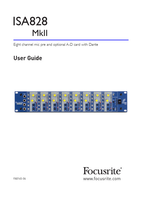
Focusrite ISA 828 MkII 八通道微机器人预置器说明书
User Guide FA0145-04Eight channel mic pre and optional A-D card with DanteISA828MkIICONTENTSAbout this User Guide (3)INTRODUCTION (4)ISA 828 MKII CONTROLS AND FEATURES (5)Front Panel (5)Channel Controls (5)Input Selection (5)Mic Input (5)Line Input (6)Instrument Input (6)Z In (Input Impedance) (6)+48V (6)Phase (6)HPF (High-Pass Filter) (6)Insert (6)Channel Meters (7)Meter Calibration (7)Rear Panel (8)AC Mains Inlet (8)Microphone Inputs (8)Line Inputs (8)Analogue Outputs (8)A-D inputs (8)Meter Trim (8)A-D Option Card Slot (8)A-D Option Card (9)A-D Card Clock and Sync Switches (10)PHYSICAL CHARACTERISTICS (11)Power Requirements (11)APPENDICES (12)1. Connector Pinouts (12)2. Preamp Input Impedance (14)3. Pro Tools Interfacing (16)PERFORMANCE AND SPECIFICATIONS (17)Focusrite RedNet Warranty and Service (19)2About this User GuideThis user guide applies to the ISA 828 MkII mic pre. It provides information about installing and using the unit, and how it can be connected into your system.Also included is information relating to the optional ISA ADN8 A-D interface card, which will allow audio from the Mic pre to be added to a Dante network.If you feel that additional information might be of assistance, be sure to consult the site:https:///technical-support, which contains a comprehensive collection of common technical support queries.Pro Tools® and Pro Tools | HD TM are trademarks or registered trademarks of Avid Technology,Inc.or its subsidiariesin the United States and/or other countries.Dante® and Audinate® are registered trademark of Audinate Pty Ltd.Box Contents• I SA 828 MkII unit• A C power lead• S afety information cut sheet3INTRODUCTIONThank you for purchasing the Focusrite ISA 828 MkII.The ISA 828 MkII is a high quality eight channel microphone preamplifier, which can be used to record microphone, line-level or instrument sources. Microphones and line-level sources for all eight inputs are connected via the rear panel, whilst instrument inputs, available on channels 1–4, can be plugged directly into the front panel jack sockets.The front panel also features gain and other settings such as phantom power and impedance for each of the eight analogue inputs. LED metering is provided on each channel in dBFS, to indicate when the level is reaching the digital clipping point – a dial for calibration is provided on the rear panel.To maintain pristine Focusrite quality in the digital domain, an Analogue-to-Digital interface card may be fitted into the option slot on the rear panel. This provides access to a Dante network and features AES3, S/PDIF and ADAT signals.With the A-D card installed, the internal/external clock sample rate and sync source can be selectedusing the switches on the front panel.45ISA 828 MKII CONTROLS AND FEATURESFront PanelInput SelectionEach press of the Input button steps through the available input sources: Mic/Line/Instrument for channels 1–4, Mic/Line for channels 5–8.Mic InputThe Gain switch sets the mic gain in 10 dB steps. Its range is either 0–30 dB or 30–60 dB when the 30–60 switch is pressed. An additional 0–20 dB of fine gain adjustment is available by using the Trim control.To avoid an excessive jump in level, It is recommended that the stepped Gain switch is turned to minimum before pressing the 30-60 switch.Before starting a recording, or if used for PA work, set the Trim control to near its centre position. This will allow forsome gradual gain adjustment up or down without the use of the stepped control.switch for channels 1–4LED meter and sync selection6Channel Controls...Line InputThe Gain switch sets the gain at between -20 dB and +10 dB in 10 dB steps. Continuous gain adjustment of up to 20 dB can be added using the Trim control.Instrument InputThe Instrument inputs are accessed via standard 1/4” mono jacks on the front panel. The level is set using the Trim control only and is continuously adjustable from +10 dB to +40 dB.Refer to the appendix on page 12 for connector pinouts.Z In (Input Impedance)With Mic input selected, pressing the Z In button steps through the fourtransformer preamp input impedance options. The values are shown in thetable.For additional information on impedance selection see Appendix 2, “Preamp InputImpedance” on page 14.With Instrument input selected, pressing the switch toggles between High andLow impedance settings, as shown in the lower table.The Line input impedance is fixed at 10 kΩ and is not affected by the Z Inswitch. +48VPressing the +48V button applies phantom power to the Mic input XLR. This switch does not affect the Line or Instrument inputs.If you are unsure whether your microphone requires phantom power please refer to its handbook. Certain microphones (most notably ribbon and unbalanced mics) could be damaged by applying phantom power.PhasePressing Phase inverts the polarity of the selected input. This can be useful when multiple mic are used in close proximity (ie., on a drum kit).HPF (High-Pass Filter)Pressing HPF inserts the 18 dB/octave 75 Hz high-pass filter into channel path; it is applied to whichever input is selected.The HPF is useful for removing any unwanted low frequencies, eg., rumble transmitted through floor mounted mic stands, etc.InsertPressing a channel’s Insert button switches the A-D option card’s input source from the channel output to the external input – ie., the same channel in the ‘A-D Inputs’ connector.The channel’s output is unaffected, allowing its signal to be processed externally and then returned to the A-D card for conversion.The return signal levels can monitored on the channel LED meters when the Meters Pre A-D switch is pressed – see Channel Meters on the next page.Low 600 ΩISA 110 1.4 kΩMed 2.4 kΩHigh 6.8 kΩLow 470 kΩHigh 2.4 MΩMic Impedance Instrument Impedance78AC Mains InletStandard IEC receptacle for AC mains. ISA 828 MkII features a ‘Universal’ PSU, enabling it to operate on any supply voltage between 100 V and 240 V AC.Microphone InputsEight latching XLR-3 female connectors.Line InputsEight balanced 1/4” TRS jack sockets.Analogue OutputsChannel outputs 1–8 on DB25 female connector. These outputs are linked internally to the A-D option card inputs, except when the Insert switches are pressed.A-D inputsEight analogue inputs to the A-D option card on DB25 female connector . Inputs are enabled individually by pressing channel Insert switches.Both DB25 connectors are wired according to the AES59 Standard (also known as the TASCAM Analogue standard). Refer to the Appendix on page 12 for connector pinouts.Meter TrimAllows the channel LED meter reading at full scale to be adjusted between 15 dBu and 26 dBu. At the central detented position the reading will be 22 dBu, which matches the maximum input level of the A-D card. Also see Meter Calibration on page 7.A-D Option Card SlotSlot for ISA ADN8 analogue to digital conversion card. The card allows audio channels from the ISA 828 MkII to be added to a Dante network. It also provides AES3, S/PDIF and ADAT signals.See the following page for A-D card details.Rear PanelMic input XLRs 1-8Line input jacks 1-8Mains inlet Analogue outputs 1-8A-D external inputs 1-8Meter Trim control Slot for A-Doption cardA-D Option CardThe optional ISA ADN8 A-D card can be retrofitted to an ISA 828 MkII at any time. Engineering experience is not required as the card can easily be installed by the user.Note that the ISA 828 MkII does not support the earlier ISA 8-Channel A-D card.Once fitted, configuration of the card is carried out over the network using either RedNet Control or the Dante Controller software application.The fitting instructions and network software applications are included with the A-D card option.Word Clock – InputAllows the card to be synchronised to an external Word Clock source via the BNC connector. Word Clock – OutputProvides an output of the external Word Clock source connected at the “Word Clock In” BNC connector or, transmits the internal sample frequency of the A-D card.• When the ISA 828 MkII is being used as a slave device within a larger digital system, the Word Clock Out connector can be used to pass on the external word clock signal to the next device.• When the unit is not slaved to another device and is in Internal Clock mode, the Word Clock Out connector outputs the sample frequency selected on the ISA 828 MkII front panel. Primary Network PortLatching RJ45 connector for the Dante network. Use standard Cat 5e or Cat 6 network cable to connect to a local Ethernet switch to connect the ISA ADN8 to the Dante network. Adjacent to each network socket are LEDs which illuminate to indicate a valid network connection and network activity. Secondary Network PortSecondary Dante network connection where two independent Ethernet links are being used (Redundant mode) or an additional port on an integral network switch on the primary network (Switched mode).ADAT I/O 1 and 2Two independent 8-channel ADAT optical inputs and outputs using standard TOSLINK connectors. AES3 Outputs 1-8Eight AES3 outputs on DB25 connector.See Appendix 1 on page 13 for connector pinouts.See Appendix 3 on page 16 for Pro Tools interfacing information.9A-D Option Card...to select the internal sample frequency: 44.1kHz, 48kHz, 88.2kHz,10PHYSICAL CHARACTERISTICSCase dimensions are illustrated in the diagram above.ISA 828 MkII requires 2U of vertical rack space. Allow an additional 75mm of rack depth behind the unit to allow for cables. ISA 828 MkII weighs 7.05 kg and for installations in a fixed environment (eg., a studio rack), the front-panel rack mountings* will provide adequate support. However, if the unit is to be used in a mobile situation (eg., flight-cased for touring, etc.), it is recommended that side support rails or shelves are used within the rack.*Always use M6 bolts and cage nuts specifically designed for 19” equipment racks. An Internet search using the phrase “M6 cage nuts“ will reveal suitable components.Cooling vents are provided at each side; ensure that when mounted in a rack these vents are not obstructed. Do not mount the unit immediately above any other equipment which generates significant heat, for example, a power amplifier.Note.The maximum operating environmental temperature is 40°C / 104°F.Power RequirementsISA 828 MkII is mains powered and incorporates a ‘Universal’ power supply which can operate on any AC mains voltage from 100 V to 240 V. The AC connection is via a standard 3-pin IEC connector on the rear panel.A mating IEC cable is supplied with each unit – this should be terminated with a mains plug of the correct type for your country.Power consumption for ISA 828 MkII is 35 W.Please note that there are no fuses or other user-replaceable components of any type in any unit. Please refer all servicing issues to the Customer Support Team (see “Customer Support and Unit Servicing” on page 19).APPENDICES1. Connector PinoutsLine Outputs / A-D InputsConnector:DB25 female (AES59 analogue)Screw binding-posts use the standard UNC 4/40 thread1132514Mic InputConnector:XLR-3 femaleInstrument InputConnector:Unbalanced (TS) 1/4” Jack socketLine InputConnector:Balanced (TRS) 1/4” Jack socketTip Ring SleeveTipSleeve1. Connector Pinouts...Network 1 & 2Connector type:RJ-45 receptacle18ADAT Optical InterfaceConnector:TOSLINKWord Clock In & OutConnector:BNC 75ΩISA ADN8 Option Card:AES3 OutputsConnector:DB25 female (AES59 digital)Screw binding-posts use the standard UNC 4/40 thread1132514Appendices...2. Preamp Input ImpedanceA major element of the sound of a mic pre is related to the interaction between the specific microphone being used and the type of mic preamp interface technology it is connected to. The main area in which this interaction has an effect is the level and frequency response of the microphone, as follows: LevelProfessional microphones tend to have low output impedances and so more level can be achieved by selecting the higher impedance positions of the ISA 828 MkII mic preamp.Frequency responseMicrophones with defined presence peaks and tailored frequency responses can be further enhanced by choosing lower impedance settings. Choosing higher input impedance values will tend to emphasise the high frequency response of the microphone connected, allowing you to get improved ambient information and high end clarity – even from average-performance microphones. Various microphone/ISA 828 MkII preamp impedance combinations can be tried to achieve the desired amount of colouration for the instrument or voice being recorded. To understand how to use the impedance selection creatively, it may be useful to read the following section on how the microphone output impedance and the mic preamp input impedance interact.Impedance Setting – Quick GuideIn general the following selections will yield the following results:High mic preamp impedance settings:• Will generate more overall level• Will tend to make low- and mid-frequency response of the microphone flatter• Will improve high-frequency response of the microphone.Low preamp impedance settings:• Will reduce the microphone output level• Will tend to emphasise the low- and mid-frequency presence peaks and resonant points of the microphoneSwitchable Impedance – In Depth ExplanationDynamic Moving Coil and Condenser MicrophonesAlmost all professional dynamic and condenser microphones are designed to have a relatively low nominal output impedance of between 150 Ω and 300 Ω when measured at 1 kHz. Microphones are designed to have such low output impedance because the following advantages result:• They are less susceptible to noise pickup• They can drive long cables without high frequency roll-off due to cable capacitanceThe side-effect of having such low output impedance is that the mic preamp input impedance has a major effect on the output level of the microphone. Low preamp impedance loads down the microphone output voltage, and emphasizes any frequency-related variation in microphone output2.Pre Amp Impedance...impedance. Matching the mic preamp resistance to the microphone output impedance (eg., making a preamp input impedance 200 Ω to match a 200 Ω microphone) still reduces the microphone output and signal to noise ratio by 6 dB, which is undesirable.To minimise microphone loading, and to maximise signal to noise ratio, preamps have traditionally been designed to have an input impedance about ten times greater than the average microphone, around 1.2 kΩ to 2 kΩ. (The original ISA 110 preamp design followed this convention and has an input impedance of 1.4 kΩ at 1 kHz.) Input impedance settings greater than 2 kΩ tend to make the frequency-related variations of microphone outputs less significant than at low impedance settings. Therefore high input impedance settings yield a microphone performance that is flatter in the low and mid frequency areas and boosted in the high frequency area when compared to low impedance settings.Ribbon MicrophonesThe impedance of a ribbon microphone is worthy of special mention, as this type of microphone is affected enormously by preamp impedance. The ribbon impedance within this type of microphone is incredibly low, around 0.2 Ω, and requires an output transformer to convert the extremely low voltage it can generate into a signal capable of being amplified by a preamp. The ribbon microphone output transformer requires a ratio of around 1:30 (primary:secondary) to increase the ribbon voltage to a useful level, and this transformer ratio also has the effect of increasing the output impedance of the mic to around 200 Ω at 1 kHz. This transformer impedance, however, is very dependent upon frequency - it can almost double at some frequencies (known as the resonance point) and tends to roll off to very small values at low and high frequencies. Therefore, as with the dynamic and condenser microphones, the mic preamp input impedance has a massive effect on the signal levels and frequency response of the ribbon microphone output transformer, and thus the ‘sound quality’ of the microphone. It is recommended that a mic preamp connected to a ribbon microphone should have an input impedance of at least 5 times the nominal microphone impedance.For a ribbon microphone impedance of 30 Ω to 120 Ω, the input impedance of 600 Ω (Low) will work fine. For 120 Ω to 200 Ω ribbon microphones, the input impedance setting of 1.4 kΩ (ISA 110) is recommended.Appendices...3. Pro Tools Interfacing• Analogue out to Pro Tools | HD• Dante to Pro Tools | HDISA 828 MkIIRed 16LinePro Tools interfacePERFORMANCE AND SPECIFICATIONSPerformance and Specifications ...Focusrite RedNet Warranty and ServiceAll Focusrite products are built to the highest standards and should provide reliable performance for many years, subject to reasonable care, use, transportation and storage.Very many of the products returned under warranty are found not to exhibit any fault at all. To avoid unnecessary inconvenience to you in terms of returning the product please contact Focusrite support.In the event of a Manufacturing Defect becoming evident in a product within 12 months from the date of the original purchase Focusrite will ensure that the product is repaired or replaced free of charge.A Manufacturing Defect is defined as a defect in the performance of the product as described and published by Focusrite. A Manufacturing Defect does not include damage caused by post-purchase transportation, storage or careless handling, nor damage caused by misuse.Whilst this warranty is provided by Focusrite the warranty obligations are fulfilled by the distributor responsible for the country in which you purchased the product.In the event that you need to contact the distributor regarding a warranty issue, or an out-of-warranty chargeable repair, please visit: /distributorsThe distributor will then advise you of the appropriate procedure for resolving the warranty issue. In every case it will be necessary to provide a copy of the original invoice or store receipt to the distributor. In the event that you are unable to provide proof of purchase directly then you should contact the reseller from whom you purchased the product and attempt to obtain proof of purchase from them.Please do note that if you purchase a Focusrite product outside your country of residence or business you will not be entitled to ask your local Focusrite distributor to honour this limited warranty, although you may request an out-of-warranty chargeable repair.This limited warranty is offered solely to products purchased from an Authorised Focusrite Reseller (defined as a reseller which has purchased the product directly from Focusrite Audio Engineering Limited in the UK, or one of its Authorised Distributors outside the UK). This Warranty is in addition to your statutory rights in the country of purchase.Registering Your ProductFor access to Dante Virtual Soundcard, please register your product at: /registerCustomer Support and Unit ServicingYou can contact our dedicated RedNet Customer Support team free of charge:Email: *****************************Phone (UK): +44 (0)1494 836384Phone (USA): +1 (310) 450-8494TroubleshootingIf you are experiencing problems with your ISA 828 MkII, we recommend that in the first instance, you visit our Support Help Centre at: https:///help-centre。
ISI921VF用户手册
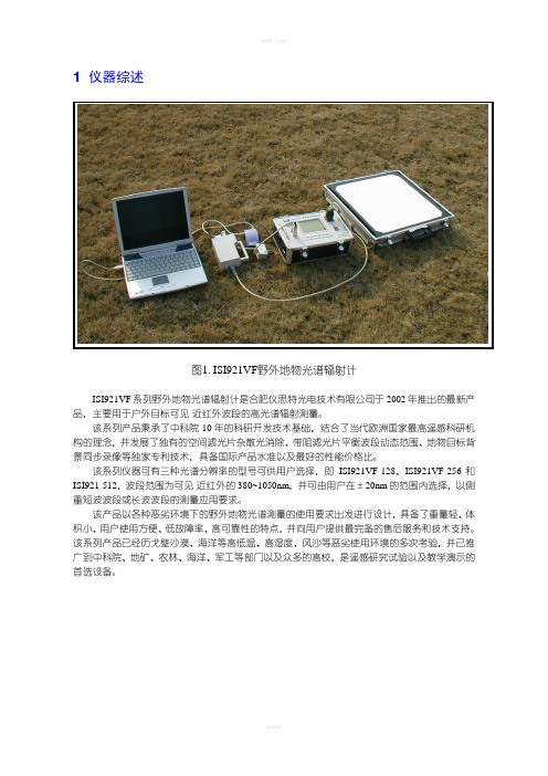
1 仪器综述图1. ISI921VF野外地物光谱辐射计ISI921VF系列野外地物光谱辐射计是合肥仪思特光电技术有限公司于2002年推出的最新产品,主要用于户外目标可见-近红外波段的高光谱辐射测量。
该系列产品秉承了中科院10年的科研开发技术基础,结合了当代欧洲国家最高遥感科研机构的理念,并发展了独有的空间滤光片杂散光消除、带阻滤光片平衡波段动态范围、地物目标背景同步录像等独家专利技术,具备国际产品水准以及最好的性能价格比。
该系列仪器可有三种光谱分辨率的型号可供用户选择,即ISI921VF-128、ISI921VF-256和ISI921-512,波段范围为可见-近红外的380~1050nm,并可由用户在±20nm的范围内选择,以侧重短波波段或长波波段的测量应用要求。
该产品以各种恶劣环境下的野外地物光谱测量的使用要求出发进行设计,具备了重量轻、体积小、用户使用方便、低故障率、高可靠性的特点,并向用户提供最完备的售后服务和技术支持。
该系列产品已经历戈壁沙漠、海洋等高低温、高湿度、风沙等恶劣使用环境的多次考验,并已推广到中科院、地矿、农林、海洋、军工等部门以及众多的高校,是遥感研究试验以及教学演示的首选设备。
2 应用性能2-1 适用场合本系列型号野外地物光谱辐射计主要应用于户外场合,利用太阳辐射作为照明光源,可测量地物目标的光谱辐亮度;利用漫反射参考板对比测量,可获得目标的反射率光谱信息;通过对经过标定的漫反射参考板的测量,可获得地面的总照度以及直射/漫射照度光谱信息;利用特定的辅助测量机械装置,可获得地面目标的BRDF(方向反射因子)光谱信息参数测量。
如使用适当的人工照明光源,本产品同样可适用于室内场合的测量。
2. 地物测量(1)图3. 地物测量(2)图敬请注意:您所选购的产品是否符合您的应用要求2-3 使用性能➢体积小、总量轻、使用方便,适合单人手持式野外操作,实现地物光谱快速获取➢可靠性强,故障率低,适合各种恶劣环境的野外测试及恶劣路况长途运输➢激光目标指示(不含ISI921VF-128)➢增益及积分时间可自动调整及人工设置➢内置二级光谱消除滤光片➢自动快门本底测量及漂移补偿➢空间滤光片杂散光消除专利技术➢带阻滤光片平衡波段动态范围专利技术➢内置聚合物锂离子电池,可长时间连续工作➢点阵液晶显示器显示操作菜单及测试曲线➢内置大容量非易失性RAM存储测量数据,测量时无需使用便携式计算机➢外接计算机数据处理,配套软件可实现多种功能➢可选地物目标背景同步显示等独家专利技术➢可选GPS模块经纬度自动检测本型号系列仪器的典型应用:曾长时间、多次应用于沙漠戈壁(风沙高温)及海冰(潮湿低温)测试注:带※项为非标准配置内容3 仪器配置4 结构及连接4-1 主机面板结构图6. 主机面板示意图部件功能描述1电源开关仪器开关电源操作2头部电缆连接插座连接光学测试头部3USB口通讯电缆插座连接笔记本或台式电脑,进行数据传输4GPS天线插座GPS接收天线(为选择配置)5充电插座主机内置鋰电池充电,※同步录像摄像头电源6液晶显示屏操作界面文字、曲线显示7对比度电位器液晶屏对比度调节8保险丝座主机保险丝9键盘数字键0~9菜单选择及数字输入确认键(ENTER)功能确认退出键(ESC)返回上级菜单复位键(RESET)系统复位4-2 光学头部结构图7. 光学头部如图所示,光学头部上有以下部件:➢电缆:用于连接主机箱➢镜头:配有与主光轴平行的半导体激光指示器➢把手:手持之用,上置有“测量”和“指示”按钮(大拇指部位)➢支架安装孔:2个M4螺孔,用于固定安装➢※摄像头:同步显示功能的图象获取;为选择配置4-3 基本配置连接注意:所有电气连接必须在关电的状态下进行,否则可能引起设备损害!4-3-1 安装如测试采用手持操作方式,则无需任何机械安装。
9211发卡机使用说明书
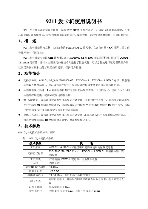
9211发卡机使用说明书9211发卡机是本公司自主研制开发的UHF RFID系列产品之一。
该发卡机具有非接触、不受环境影响、读写距离远、适应物体高速运动性能好、操作方便、防冲突等优良特性,用途极其广泛。
1、概述9211发卡机是结构完整、功能齐全的915M的RFID读写器,它含有射频(RF)模块、数字信号处理和串行通信接口。
9211发卡机是多协议UHF读写器,支持ISO18000-6B和EPC协议国际标准,能读写UCODE、TI、Alian等标签,并针对主要应用的标签芯片进行了性能优化。
可以方便地进行读写器软件升级,以满足协议扩展和功能扩展的应用需要,保护用户投资。
2、功能简介●支持多协议:9211发卡机支持ISO18000-6B、EPC Class 1、EPC Class 1 GEN 2标准、集装箱标签以及铁路标签,,也可以通过在应用升级读写器软件以支持更多协议和功能扩展。
●标签性能优化功能:9系列读写器针对广泛使用的标签操作进行了性能优化,使用了各个不同标签的扩展功能,提高系统应用的性价比。
●ID匹配功能:读写器内设计有外部非易失存储空间,在封闭应用系统中,可以预先将本系统发行的标签ID存储在存储器中,当读写器识别到标签ID后与本机存储的ID进行比较,依据比较的结果执行读写器预定义或用户设计的动作。
●离线工作功能:读写器内设计有外部非易失存储空间,在读写器与应用系统通信失败的情况下,可以将识别的标签ID存储在读写器中,保证系统稳定工作。
3、技术参数9211发卡机技术参数如表1所示:表1 9211发卡机技术参数4、安装方法及注意事项本套产品包含9211发卡机一台、RS232串口通信线一条、USB通信线一条、+5V/5A电源适配器一个。
请您打开包装盒后确认配件是否齐全,如有问题请速于经销商或直接于本公司售后服务部联系。
4.1、外观本发卡机外型为长方体,机体主色为白色。
发卡机的一侧,左起依次是直流电源输入接口、串行通信接口和USB接口(9211B型)。
Telegesis ETRX2USB 无线网络USB闪卡说明书

ETRX2USB and ETRX2USB-PA USB STICKPRODUCT MANUALTelegesis™ is a trademark of Silicon Laboratories Inc.N o tRe co m m e nd edf or N e wDe si gnTable of Contents1 INTRODUCTION ................................................................................................................. 3 1.1 Supported Operating Systems .. (3)2 ABSOLUTE MAXIMUM RATINGS ..................................................................................... 3 3 OPERATING CONDITIONS (4)4 OTHER DATA ..................................................................................................................... 4 5 ETRX2 I/O CONNECTIVITY .. (5)6 FIRMWARE UPGRADES (5)7 DRIVER INSTALLATION AND OPERATION ..................................................................... 6 7.1 Windows 9x/XP/2k Driver Installation ............................................................................... 6 7.2 Macintosh and Linux drivers ............................................................................................. 9 8 CUSTOM FIRMWARE DEVELOPMENT ............................................................................ 9 9 ORDERING INFORMATION (10)N o tRe co m m e nd edf or N e wDe si gn1 IntroductionThe ETRX2USB wireless mesh networking USB Stick is effectively an RS232 to USB bridge connected to an ETRX2 ZigBee module. This allows connectivity to a computer’s USB port. The supplied drivers create a virtual COM Port, so that the command line of the ETRX2 can be accessed via any terminal software application.When using Windows ® 9x/XP/2000 the Telegesis Terminal application can be used as described in the Development Kit manual.1.1 Supported Operating Systems∙ Windows 98SE ∙ Windows XP ∙ Windows 2000 ∙ MAC OS-9 ∙ MAC OS-X ∙ Linux2 Absolute Maximum RatingsTable 1: Absolute Maximum RatingsThe absolute maximum ratings given above should under no circumstances be violated. Exceeding one or more of the limiting values may cause permanent damage to the device.N o tRe co m edf or N e wDe si gn3 Operating ConditionsTypical values at 5V 25°C.Table 2: Operating Conditions4 Other dataFor further technical information, including radio certification, see the ETRX2 or ETRX2PA Module Product Manual.If you purchase ETRX2USB sticks without printed markings on the case, you may be responsible for applying a marking appropriate to their geographical area of use, such as the FCC certification. For more information on ZigBee® compliance and the AT command interface firmware please refer to the latest AT command dictionary and the ETRX2 user guide.1 During USB suspend the current will drop by 25.6mA in all modes.2 Please note that the power consumption in various power modes is firmware and usage dependent.N o tRe co mm e nd en5 ETRX2 I/O ConnectivityThe I/Os of the built in ETRX2 are connected as follows:∙ I/O1 is connected to the LED (drive I/O1 low to sink LED).∙ I/O2 is the CTS input for the ETRX2. Make sure I/O2 is never defined as an output. ∙ I/O4 is the RTS input for the ETRX2.Important Note: The lines for hardware handshaking are connected, so even when not using hardware handshaking I/O2 should never be defined as an output as this would drive against the incoming CTS signal via a 1k Ω resistor and increase the current consumption.Note that if you use the command “AT&F” on the USB stick, I/O1 will revert to being an input and the LED will not light up. To restore its function as a pilot light, use the command “ATS0E=00FA” (with R2xx firmware) or “ATS17=00FA” (with R3xx) followed by a reset.6 Firmware upgradesThe firmware which is loaded onto the embedded ETRX2 Module can be upgraded over the air or via the virtual COM port as described in the Development Kit manual.Alternatively, access to the SIF programming interface is possible by opening the cover on the side of the ETRX2USB ZigBee USB stick.N o tRe co m m e nd edf or N e wDe si gn7 Driver Installation and OperationThe drivers provided will generate a virtual COM port allowing easy access to the serial port of the embedded ETRX2.To read more about the ETRX2 wireless mesh networking module and its command line interface please read the corresponding documentation which can be found at /telegesisdocuments .7.1 Windows 9x/XP/2k Driver InstallationThe driver package downloadable from the Support Software download page of /telegesissoftware should be unzipped into a local folder. When executing the file ‘TgVCPInstaller.exe ’ prior to plugging in the ETRX2USB stick an installer will guide you through the steps required for the driver installation. If prompted that the driver has not passed the W indows logo test simply press ‘Continue Anyway’.Figure 1: Found New Hardware WizardAfter insertion of the stick, Windows ® will prompt that new hardware has been found. If you have run the ‘TgVCPInstaller.exe ’ Windows will be able to install the driver by automatically as shown in Figure 2. If you have not run ‘TgVCPInstaller.exe ’ you will have to manually point to the directory into which you have unzipped the driver.N o tRe co m m e nd edf or N e wDe si gnFigure 2: Install software AutomaticallyFigure 3: Windows Logo TestPlease note that each ETRX2USB has a unique serial number which requires the installation procedure to be repeated with every new ETRX2USB being attached to the computer. This allows multiple ETRX2USB sticks to be used on the same computer at any one time.In order to find out the identity/number of the virtual com port the stick has been assigned to, please enter the Device Manager under the Windows Computer Management screen (see below) and click on the Ports (COM and LPT) section where you should find the new virtual COM port. By double clicking on the entry of the virtual COM port you can also change the number assigned to the virtual COM port when entering the advanced setup of the device.N o tRe co m m e nd edf or N e wDe si gnFigure 4. Device ManagerOnce the correct COM port has been selected, the Terminal software can be used to control the ETRX2USB stick as per the Development Kit Manual.Figure 5. Telegesis TerminalN o tRe co m m e nd edf or N e wDe si gn7.2 Macintosh and Linux driversA Virtual Com Port driver kit for Mac and Linux can be obtained by following the link on our website on the Support Software download page.In addition, one of our customers has written a Linux driver that will be included in the 2.6.25 kernel. It can be found at /pub/linux/kernel/people/gregkh/gregkh-2.6/patches/. (Note that this is for information only, and this software was developed entirely outside Telegesis.) Most Linux distributions now include suitable native drivers.8 Custom Firmware DevelopmentIf you intend to develop custom firmware to go onto the ETRX2USB you need to contact SiLabs to obtain access to their suite of development tools and their stack. The USB stick contains an ETRX2 module based on the SiLabs EM250 and a USB-to-serial bridge chip. The ETRX2 communicates via its serial port , so the user’s firmware must use the UART of Serial Controller 1. The nRTS and nCTS lines are connected to the USB bridge chip. The LED on the USB stick is driven from ETRX2 pad I/O1, which is EM250 pin GPIO14.In order to download custom firmware onto the ETRX2, the Ember bootloader can be used or alternatively the ETRX2USB can be directly connected to the Ember InSight Adapter for programming and real time debugging.N o tRe co m m e nd edf or N e wDe si gn9 Ordering InformationTable 11. Ordering InformationN o tRe c Silicon Laboratories Inc.400 West Cesar Chavez Austin, TX 78701USASmart.Connected.Energy-Friendly Products/products Quality /quality Support and Community Disclaimer Silicon Laboratories intends to provide customers with the latest, accurate, and in-depth documentation of all peripherals and modules available for system and software implementers using or intending to use the Silicon Laboratories products. Characterization data, available modules and peripherals, memory sizes and memory addresses refer to each specific device, and "Typical" parameters provided can and do vary in different applications. Application examples described herein are for illustrative purposes only. Silicon Laboratories reserves the right to make changes without further notice and limitation to product information, specifications, and descriptions herein, and does not give warranties as to the accuracy or completeness of the included information. Silicon Laboratories shall have no liability for the consequences of use of the information supplied herein. This document does not imply or express copyright licenses granted hereunder to design or fabricate any integrated circuits. The products are not designed or authorized to be used within any Life Support System without the specific written consent of Silicon Laboratories. A "Life Support System" is any product or system intended to support or sustain life and/or health, which, if it fails, can be reasonably expected to result in significant personal injury or death. Silicon Laboratories products are not designed or authorized for military applications. Silicon Laboratories products shall under no circumstances be used in weapons of mass destruction including (but not limited to) nuclear, biological or chemical weapons, or missiles capable of delivering such weapons.Trademark Information Silicon Laboratories Inc.® , Silicon Laboratories®, Silicon Labs®, SiLabs® and the Silicon Labs logo®, Bluegiga®, Bluegiga Logo®, Clockbuilder®, CMEMS®, DSPLL®, EFM®, EFM32®, EFR, Ember®, Energy Micro, Energy Micro logo and combinations thereof, "the world’s most energy friendly microcontrollers", Ember®, EZLink®, EZRadio®, EZRadioPRO®, Gecko®, ISOmodem®, Precision32®, ProSLIC®, Simplicity Studio®, SiPHY®, Telegesis, the Telegesis Logo®, USBXpress® and others are trademarks or registered trademarks of Silicon Laborato-ries Inc. ARM, CORTEX, Cortex-M3 and THUMB are trademarks or registered trademarks of ARM Holdings. Keil is a registered trademark of ARM Limited. All other products or brand names mentioned herein are trademarks of their respective holders. N o t R e co m m e n d e d f o r N e w D e s i g n。
COMBO-XRotor-X11-14S无刷动力系统用户手册说明书

Voltage(V)工作电压Propeller螺旋桨Throttle(%)油门Thrust(g)拉力Current(A)电流Power(W)输入功率Speed(RPM)转速Efficiency(g/W)效率54V (14S LIPO)41*13.5InchFoldablePropeller40%886015.7850.6190910.442%968018.1979.519989.944%1076021.41160.221119.346%1151023.91291.221868.948%1240026.81450.922718.550%1275028.01514.623038.452%1401532.31748.824168.054%1540037.22010.525317.756%1638540.72199.726087.458%1733544.12384.926797.360%1886549.82691.127897.062%1938551.72797.82825 6.964%2077557.23092.12919 6.766%2187561.73336.22992 6.668%2309067.03620.13071 6.470%2453073.63979.83164 6.272%2563579.14275.13236 6.074%2627582.44454.53277 5.976%2763589.94857.63365 5.778%2883096.95236.93441 5.580%30290106.15732.43533 5.3100%33970131.77112.83741 4.8【保护功能】1)启动保护:当正常接电时电调首先启动自检,自检成功则可正常鸣叫后运行,若自检不通过则无法启动同时闪灯警示。
2)堵转保护:当电调检测到电机发生堵转时,电调会彻底关闭输出并不再尝试重启电机,此时需重新上电方可清除错误并重启电调恢复动力输出。
