MS3126E16-26SW;中文规格书,Datasheet资料
SW-261中文资料
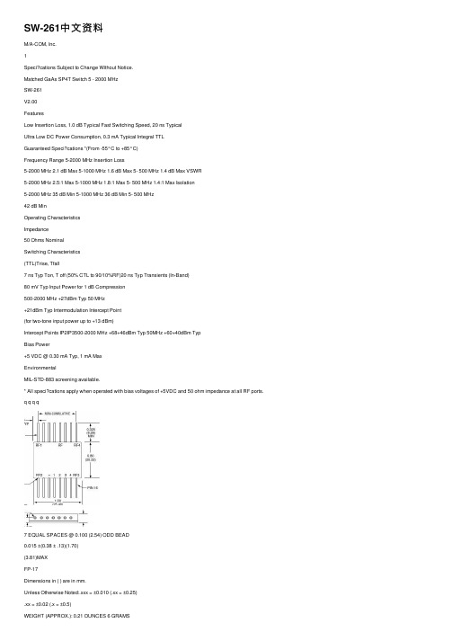
SW-261中⽂资料M/A-COM, Inc.1Speci?cations Subject to Change Without Notice.Matched GaAs SP4T Switch 5 - 2000 MHzSW-261V2.00FeaturesLow Insertion Loss, 1.0 dB Typical Fast Switching Speed, 20 ns TypicalUltra Low DC Power Consumption, 0.3 mA Typical Integral TTLGuaranteed Speci?cations *(From -55°C to +85°C)Frequency Range 5-2000 MHz Insertion Loss5-2000 MHz 2.1 dB Max 5-1000 MHz 1.6 dB Max 5- 500 MHz 1.4 dB Max VSWR5-2000 MHz 2.5:1 Max 5-1000 MHz 1.8:1 Max 5- 500 MHz 1.4:1 Max Isolation5-2000 MHz 35 dB Min 5-1000 MHz 36 dB Min 5- 500 MHz42 dB MinOperating CharacteristicsImpedance50 Ohms NominalSwitching Characteristics(TTL)Trise, Tfall7 ns Typ Ton, T off (50% CTL to 90/10%RF)20 ns Typ Transients (In-Band)80 mV Typ Input Power for 1 dB Compression500-2000 MHz +27dBm Typ 50 MHz+21dBm Typ Intermodulation Intercept Point(for two-tone input power up to +13 dBm)Intercept Points IP2IP3500-2000 MHz +68+46dBm Typ 50MHz +60+40dBm TypBias Power+5 VDC @ 0.30 mA Typ, 1 mA MaxEnvironmentalMIL-STD-883 screening available.* All speci?cations apply when operated with bias voltages of +5VDC and 50 ohm impedance at all RF ports. q q q q7 EQUAL SPACES @ 0.100 (2.54) ODD BEAD0.015 ±(0.38 ± .13)(1.70)(3.81)MAXFP-17Dimensions in ( ) are in mm.Unless Otherwise Noted:.xxx = ±0.010 (.xx = ±0.25).xx = ±0.02 (.x = ±0.5)WEIGHT (APPROX.): 0.21 OUNCES 6 GRAMSOrdering InformationModel No.Package SW-261 PINFlatpack元器件交易⽹/doc/a94be21f14791711cc791767.html M/A-COM, Inc.2Speci?cations Subject to Change Without Notice.Matched GaAs SP4T Switch SW-261V2.00.0.8.6.4.2.0VSWR+85°C-55°C元器件交易⽹/doc/a94be21f14791711cc791767.html。
26LS31中文资料
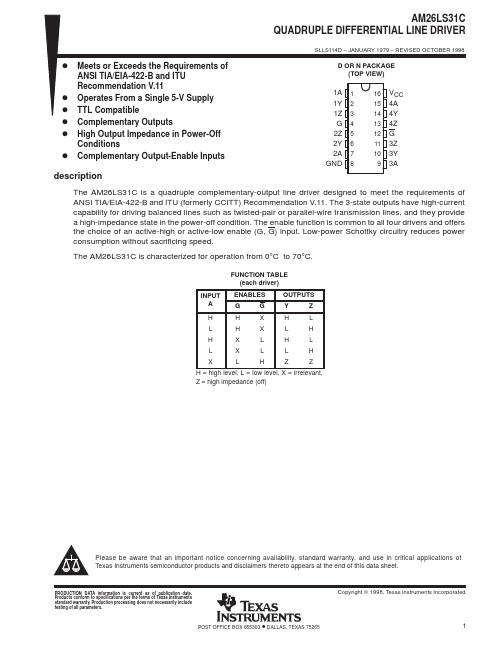
元器件交易网IMPORTANT NOTICETexas Instruments and its subsidiaries (TI) reserve the right to make changes to their products or to discontinueany product or service without notice, and advise customers to obtain the latest version of relevant informationto verify, before placing orders, that information being relied on is current and complete. All products are soldsubject to the terms and conditions of sale supplied at the time of order acknowledgement, including thosepertaining to warranty, patent infringement, and limitation of liability.TI warrants performance of its semiconductor products to the specifications applicable at the time of sale inaccordance with TI’s standard warranty. Testing and other quality control techniques are utilized to the extentTI deems necessary to support this warranty. Specific testing of all parameters of each device is not necessarilyperformed, except those mandated by government requirements.CERTAIN APPLICATIONS USING SEMICONDUCTOR PRODUCTS MAY INVOLVE POTENTIAL RISKS OFDEATH, PERSONAL INJURY, OR SEVERE PROPERTY OR ENVIRONMENTAL DAMAGE (“CRITICALAPPLICATIONS”). TI SEMICONDUCTOR PRODUCTS ARE NOT DESIGNED, AUTHORIZED, ORWARRANTED TO BE SUITABLE FOR USE IN LIFE-SUPPORT DEVICES OR SYSTEMS OR OTHERCRITICAL APPLICATIONS. INCLUSION OF TI PRODUCTS IN SUCH APPLICATIONS IS UNDERSTOOD TOBE FULLY AT THE CUSTOMER’S RISK.In order to minimize risks associated with the customer’s applications, adequate design and operatingsafeguards must be provided by the customer to minimize inherent or procedural hazards.TI assumes no liability for applications assistance or customer product design. TI does not warrant or representthat any license, either express or implied, is granted under any patent right, copyright, mask work right, or otherintellectual property right of TI covering or relating to any combination, machine, or process in which suchsemiconductor products or services might be or are used. TI’s publication of information regarding any thirdparty’s products or services does not constitute TI’s approval, warranty or endorsement thereof.Copyright © 1998, Texas Instruments Incorporated。
ADZS-BF609-EZLITE;ADZS-BF609-EZBRD;中文规格书,Datasheet资料
ADSP-BF609 EZ-KIT Lite®Evaluation System ManualRevision 1.0, March 2012Part Number82-000269-01 Analog Devices, Inc.One T echnology WayaNorwood, Mass. 02062-9106Copyright Information© 2012 Analog Devices, Inc., ALL RIGHTS RESERVED. This docu-ment may not be reproduced in any form without prior, express writtenconsent from Analog Devices, Inc.Printed in the USA.DisclaimerAnalog Devices, Inc. reserves the right to change this product withoutprior notice. Information furnished by Analog Devices is believed to beaccurate and reliable. However, no responsibility is assumed by AnalogDevices for its use; nor for any infringement of patents or other rights ofthird parties which may result from its use. No license is granted by impli-cation or otherwise under the patent rights of Analog Devices, Inc. Trademark and Service Mark NoticeThe Analog Devices logo, Blackfin, CrossCore, EZ-Board, EZ-Extender, and EZ-KIT Lite are registered trademarks of Analog Devices, Inc.All other brand and product names are trademarks or service marks oftheir respective owners.Regulatory ComplianceThe ADSP-BF609 EZ-KIT Lite is designed to be used solely in a labora-tory environment. The board is not intended for use as a consumer end product or as a portion of a consumer end product. The board is an open system design which does not include a shielded enclosure and therefore may cause interference to other electrical devices in close proximity. This board should not be used in or near any medical equipment or RF devices.The ADSP-BF609 EZ-KIT Lite is currently being processed for certifica-tion that it complies with the essential requirements of the EuropeanEMC directive 2004/108/EC and therefore carries the “CE” mark.The EZ-KIT Lite evaluation system contains ESD (electrostatic discharge)sensitive devices. Electrostatic charges readily accumulate on the humanbody and equipment and can discharge without detection. Permanent dam-age may occur on devices subjected to high-energy discharges. Proper ESDprecautions are recommended to avoid performance degradation or loss offunctionality. Store unused EZ-KIT Lite boards in the protective shippingpackage.PREFACEProduct Overview (xii)Purpose of This Manual (xv)Intended Audience (xv)Manual Contents (xvi)What’s New in This Manual (xvi)Technical or Customer Support (xvii)Supported Processors (xvii)Product Information (xviii)Analog Devices Web Site (xviii)EngineerZone (xviii)Related Documents (xix)Notation Conventions (xx)USING ADSP-BF609 EZ-KIT LITEPackage Contents .......................................................................... 1-2 ADSP-BF609 EZ-Board ................................................................ 1-3 Default Configuration ................................................................... 1-3 Supported Operating Systems ....................................................... 1-5ADSP-BF609 EZ-KIT Lite Evaluation System Manual vSystem Requirements .................................................................... 1-5 EZ-KIT Lite Installation ............................................................... 1-6 EZ-KIT Lite Session Startup ......................................................... 1-7 Evaluation License Restrictions ................................................... 1-10 Memory Map ............................................................................. 1-10 DDR2 SDRAM .......................................................................... 1-12 SPI Interface .............................................................................. 1-13 SMC Interface ............................................................................ 1-13 Ethernet Interface ....................................................................... 1-13 USB OTG HS Interface .............................................................. 1-14 CAN Interface ............................................................................ 1-14 UART Interface .......................................................................... 1-15 SD Interface ............................................................................... 1-16 Rotary Encoder Interface ............................................................ 1-16 Temperature Sensor Interface ...................................................... 1-17 Link Ports Interface .................................................................... 1-17 General-Purpose I/O (GPIO) ...................................................... 1-18 JTAG Interface ........................................................................... 1-18 Power-On-Self Test ..................................................................... 1-20 Expansion Interface III ............................................................... 1-20 Power Architecture ..................................................................... 1-21 Power Measurements .................................................................. 1-21 Example Programs ...................................................................... 1-22 Reference Design Information ..................................................... 1-22vi ADSP-BF609 EZ-KIT Lite Evaluation System ManualADSP-BF609 EZ-KIT LITE HARDWARE REFERENCE System Architecture ...................................................................... 2-2 Software-Controlled Switches (SoftConfig) .................................... 2-3 Overview of SoftConfig ........................................................... 2-3SoftConfig on the ADSP-BF609 EZ-KIT LITE ...................... 2-7Programming SoftConfig Switches ........................................... 2-8 Push Buttons and Switches .......................................................... 2-17 JTAG Interface Switches (SW1, SW3–5) ................................ 2-18Boot Mode Select Switch (SW2) ............................................ 2-19IRQ/Flag Enable Switches (SW6–7) ....................................... 2-20Reset Switch (SW8) ............................................................... 2-20Rotary Encoder With Momentary Switch (SW9) .................... 2-20Wake Push Switch (SW10) .................................................... 2-21 Power Jumpers ............................................................................ 2-21 LEDs .......................................................................................... 2-22 GPIO LEDs (LED1–4) ......................................................... 2-23Thermal Limit LED (LED5) ................................................. 2-23Power LED (LED6) ............................................................... 2-23Reset LED (LED7) ................................................................ 2-24SPD LED (LED6) ................................................................. 2-24 Connectors ................................................................................. 2-24 DCE UART Connector (J2) .................................................. 2-25Link Port /JTAG Connectors (J3 and P8) ............................... 2-25JTAG Connector (P1) ........................................................... 2-25 ADSP-BF609 EZ-KIT Lite Evaluation System Manual viiJTAG Connector (ZP1) ......................................................... 2-26Expansion Interface III Connectors (P1A–C, P2A, P3A) ........ 2-26USB Connector (P7) ............................................................. 2-26Power Connector (P18) ......................................................... 2-26CAN Connector (J4) ............................................................ 2-27SD Connector (J5) ................................................................ 2-27Ethernet Connector (J1) ....................................................... 2-27Ethernet Connectors (P16-17) ............................................... 2-27 ADSP-BF609 EZ-KIT LITE BILL OF MATERIALSADSP-BF609 EZ-KIT LITE SCHEMATICTitle Page ..................................................................................... B-1 Processor DDR2 Interface ............................................................ B-2 Processor Signals ........................................................................... B-3 Processor Power and Ground ......................................................... B-4 Temp Sensor, Boot Switch, DSP CLK, USB Conn ......................... B-5 Memory ....................................................................................... B-6 UART0 ........................................................................................ B-7 CAN and Rotary Encoder ............................................................. B-8 Ethernet ....................................................................................... B-9JTAG, Link Port 0 and 1 ........................................................... B-10 Push Buttons, Reset, LEDs ......................................................... B-11 SoftConfig Switches, IO Extender ICs ......................................... B-12 Expansion Interface, Page 1 ........................................................ B-13viii ADSP-BF609 EZ-KIT Lite Evaluation System ManualExpansion Interface, Page 2 ........................................................ B-14 Expansion Interface, Page 3 ........................................................ B-15 Power ........................................................................................ B-16 INDEXADSP-BF609 EZ-KIT Lite Evaluation System Manual ixx ADSP-BF609 EZ-KIT Lite Evaluation System Manual分销商库存信息: ANALOG-DEVICESADZS-BF609-EZLITE ADZS-BF609-EZBRD。
DIN_3126_2004_01
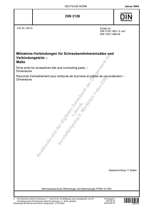
A us dr u ck ea us de rd i g i t al e n D a t e n b a n k d e r D r äg e r w e r k A GL üb e c k . Ve rv i el f äl t i g un g l t . M e r k b l a t t 3 d e s D I N .-DQXDU'(876&+( 12501RUPHQDXVVFKXVV :HUN]HXJH XQG 6SDQQ]HXJH ):6 LP ',1Preisgruppe 9DIN Deutsches Institut für Normung e.V. • Jede Art der Vervielfältigung, auch auszugsweise, nur mit Genehmigung des DIN Deutsches Institut für Normung e. V., Berlin, gestattet.,&6:"9522810www.din.de X',10LWQDKPH 9HUELQGXQJHQ I U 6FKUDXEHQGUHKHUHLQVlW]H XQG9HUELQGXQJVWHLOH ±0D H'ULYH HQGV IRU VFUHZGULYHU ELWV DQG FRQQHFWLQJ SDUWV ±'LPHQVLRQV5DFFRUGV G¶HQWUDvQHPHQW SRXU HPERXWV GH WRXUQHYLV HW SLqFHV GH UDFFRUGHPHQW ±'LPHQVLRQV©Alleinverkauf der Normen durch Beuth Verlag GmbH, 10772 Berlin (UVDW] I U',1 XQG ',1www.beuth.de*HVDPWXPIDQJ 6HLWHQA us dr u ck ea us de rd i g i t al e n D a t e n b a n k d e r D r äg e r w e r k A GL üb e c k . Ve rv i el f äl t i g un g l t . M e r k b l a t t 3 d e s D I N .DIN 3126:2004-012VorwortDiese Norm wurde vom Normenausschuss Werkzeuge und Spannzeuge (FWS), Arbeitsausschuss G 1…Schraubwerkzeuge“ erarbeitet.Zusammenhang mit den von der International Organization for Standardization (ISO) herausgegebenen Internationalen Normen:Die Mitnahme-Verbindungen dieser Norm entsprechen in den Formen A bis H mit Ausnahme von Nut und Sprengring in Form D der von der International Organization for Standardization (ISO) herausgegebenen Norm:ISO 1173:2001, Assembly tools for screws and nuts — Drive ends for hand- and machine-operatedscrewdriver bits and connecting parts — Dimensions, torque testingund:Die Mitnahme-Verbindungen in den Formen I und K entsprechen der Norm:ISO 2352:2000, Assembly tools for screws and nuts — Spiral ratchet screwdriver ends — Dimensions Um die Beziehung zwischen den zusammengehörigen Maßen der Außen- und Innensechskante bzw. der Außen- und Innenflachkante deutlicher hervorzuheben, ist die Norm redaktionell so gestaltet, dass die Maßbuchstaben für die Aufnahmen nur mit ungeraden Indizes (1, 3, 5 ...) und die für die Schäfte mit geraden Indizes (2, 4, 6 ...) versehen sind.Um die Eckenmaße der Sechskant-Verbindungen gleichmäßig untereinander abzustimmen, wurden sie nach folgenden Gleichungen errechnet e 1max = 1,13 s 1max e 1min = 1,13 s 1min e 2min = 1,13 s 2 minÄnderungenGegenüber DIN 3126:1993-12 und DIN 7432:1988-05 wurden folgende Änderungen vorgenommen:a) Drillschraubendreher-Enden wurden aus ISO 2352:2000 übernommen;b) die Norm wurde redaktionell überarbeitet.Frühere AusgabenDIN 3126: 1967-03, 1971-03, 1976-04, 1986-12, 1993-12DIN 7432: 1969-05, 1976-04, 1998-05A us dr u ck ea us de rd i g i t al e n D a t e n b a n k d e r D r äg e r w e r k A GL üb e c k . Ve rv i el f äl t i g un g l t . M e r k b l a t t 3 d e s D I N .DIN 3126:2004-0131 AnwendungsbereichDiese Norm gilt für Mitnahme-Verbindungen für hand- und maschinenbetätigte Schraubendrehereinsätze sowie für die Antriebsspindeln von Maschinenschraubern. Sie soll die Austauschbarkeit der Werkzeug-Einsätze und Werkzeugträger sicherstellen.Angegeben sind nur die Unterscheidungsmerkmale der einzelnen Verbindungen. Konstruktive Einzelheiten,z. B. über die Halterung, bleiben dem Anwender der Norm überlassen.2 Normative VerweisungenDiese Norm enthält durch datierte oder undatierte Verweisungen Festlegungen aus anderen Publikationen.Diese normativen Verweisungen sind an den jeweiligen Stellen im Text zitiert, und die Publikationen sind nachstehend aufgeführt. Bei datierten Verweisungen gehören spätere Änderungen oder Überarbeitungen dieser Publikationen nur zu dieser Norm, falls sie durch Änderung oder Überarbeitung eingearbeitet sind. Bei undatierten Verweisungen gilt die letzte Ausgabe der in Bezug genommenen Publikation (einschließlich Änderungen).DIN EN 10270-1, Stahldraht für Federn — Teil 1: Patentiert-gezogener unlegierter Federstahldraht; Deutsche Fassung EN 10270-1:2001.A us dr u ck ea us de rdi g i t al e n D a t e n b a n k d e r D r äg e r w e r k A GL üb e c k . Ve rv i el f äl t ig un g l t . M e r k b l a t t 3 d e s D I N .DIN 3126:2004-0143 Maße, BezeichnungNicht angegebenen Einzelheiten sind zweckentsprechend zu wählen.Maße in MillimeteraHaltesystem nach Wahl des HerstellersBild 1 — Schaft Form ABild 2 — Aufnahme Form BBezeichnung eines Schaftes Form A von Nenngröße 3:Schaft DIN 3126 — A 3Bezeichnung einer Aufnahme Form B von Nenngröße 3:Aufnahme DIN 3126 — B 3Tabelle 1 — Schaft Form AMaße in Millimeters 1d 1d 3e 1l 1l 3l 5rFormNenn-größemax.min.h9h12max.min.min.02,0-4,00+min.332,963,633,393,3419,511,9 7,41A5,55,505,456,75,76,216,16241610,91,25Tabelle 2 — Aufnahme Form BMaße in Millimeters 2d 2e 2l 2l 4l 6FormNenn-größemax.min.D10min.± 0,12,00+04,0-33,063,023,63,4116,511,9 7,2B5,55,585,536,76,25211610,7A us dr u ck ea us de rd i g i t al e n D a t e n b a n k d e r D r äg e r w e r k A GL üb e c k . Ve rv i el f äl t i g un g l t . M e r k b l a t t 3 d e s D I N .DIN 3126:2004-015Nenngröße 4Maße in MillimeterNenngrößen 6,3, 8 und 12,5a 40°£ = £ 60°b80°£ > £ 120°Bild 3 — Schaft Form CBezeichnung eines Schaftes Form C von Nenngröße 8:Schaft DIN 3126 — C 8Tabelle 3 — Schaft Form CMaße in Millimeters 1d 3e 1l 1l 3rFormNenn-größemax.min.h12max.min.min.2,0-min.4 3,96 3,91— 4,48 4,4294—6,3 6,35 6,29 6,7 7,18 7,11118,28 7,93 7,87 8,2 8,96 8,9013,510,2C12,512,7012,6313,514,3514,2715,912,70,3A us dr u ck ea us de rd i g i t al e n D a t e n b a n k d e r D r äg e r w e r k A GL üb e c k . Ve rv i el f äl t i g un g l t . M e r k b l a t t 3 d e s D I N .DIN 3126:2004-016Maße in MillimeterNenngrößen 6,3, 8 und 12,5aHaltesystem nach Wahl des HerstellersBild 4 — Aufnahme Form DBezeichnung einer Aufnahme Form D von Nenngröße 8:Aufnahme DIN 3126 — D8Tabelle 4 — Aufnahme Form DMaße in Millimeters 2e 2l 2l 4FormNenn-größe max.min.min.± 0,12,00+4 4,04 3,994,51 8 46,3 6,45 6,397,2210 8,288,03 7,97912,510,2D12,512,8012,7514,414,912,7A us dr u ck ea us de rdi g i t al e n D a t e n b a n k d e r D r äg e r w e r k A GL üb e c k . Ve rv i el f äl t i g un g l t . M e r k b l a t t 3 d e s D I N .DIN 3126:2004-017Maße in MillimeteraHaltesystem nach Wahl des HerstellersBild 5 — Schaft Form EBild 6 — Aufnahme Form FBezeichnung eines Schaftes Form E von Nenngröße 11,2:Schaft DIN 3126 — E 11,2Bezeichnung einer Aufnahme Form F von Nenngröße 11,2:Aufnahme DIN 3126 — F 11,2Tabelle 5 — Schaft Form EMaße in Millimeters 1d 3e 1l 1l 3l 7rFormNenn-größemax.min.h12max.min.min.01,0-»min.6,3 6,35 6,294,7 7,18 7,11259,512,4(8)a 7,93 7,876,3 8,96 8,90275,41,22,4E11,211,1111,048,712,5612,4831,56,71,22,8aEingeklammerte Nenngröße möglichst vermeiden.Tabelle 6 — Aufnahme Form FMaße in Millimeters 2e 2l 2l 4FormNenn-größemax.min.min.max.1,00+ 6,3 6,45 6,397,22249,5(8)a 8,03 7,97925,55,4F11,211,2311,1612,61306,7aEingeklammerte Nenngröße möglichst vermeiden.Aus dr u ck ea us de rdi g i t al e n D a t e n b a n k d e r D r äg e r w e r k A GL üb e c k . Ve rv i el f äl t i g un g l t . M e r k b l a t t 3 d e s D I N .DIN 3126:2004-018Maße in Millimeter Maße in MillimeteraHaltesystem nach Wahl des HerstellersBild 7 — Schaft Form GBild 8 — Aufnahme Form HBezeichnung eines Schaftes Form G von Nenngröße 7:Schaft DIN 3126 — G 7Bezeichnung einer Aufnahme Form H von Nenngröße 7:Aufnahme DIN 3126 — H 7Tabelle 7 — Schaft Form GMaße in Millimeterd 1d 3e 1l 1l 3l 5rForm Nenn-größe f8h12max.min.min.± 0,2± 0,2min.G775,83,863,742620141,5Tabelle 8 — Aufnahme Form HMaße in Millimeterd 2e 2l 2l 4r 6FormNenn-größe H101,00+max.min.± 0,2H 774,12620,514A us dr uck ea us de rd i g i t al e n D a t e n b a n k d e r D r äg e r w e r k A GL üb e c k . Ve r v i el f äl t i g un g l t . M e r k b l a t t 3 d e s D I N .DIN 3126:2004-019Maße in MillimeterLegende1Form I Schaft mit V-förmiger Nut 2Prüfkugel oder -stift Æ 3 001,0-3Form I Schaft mit kreisbogenförmiger Ringnuta R 0,2 max. oder 0,2 max. ´ 45°bR 3 max. oder 3 ´ 45° max.Bild 9 — Schaft Form IBezeichnung eines Schaftes Form I der Nenngröße 7:Schaft DIN 3126 — I 7Tabelle 9 — Schaft Form IMaße in Millimeterd 1a 1c d 3el 1l 3FormNenn-größe01,0-05,020,0--02,0-02,0-min.± 0,15,55,52,613,97,72711,1773,31,65,49,23113,5I883,725,89,93113,5A us dr u ck eaus de rdi g i t al e n D a t e n b a n k d e r D r äg e r w e r k A GL üb e c k . Ve rv i el f äl t i g un g l t . M e r k b l a t t 3 d e s D I N .DIN 3126:2004-0110Maße in MillimeterLegende1Prüfkugel oder -stift Æ d 42Form KHülseBild 10 — Aufnahme Form KBezeichnung einer Aufnahme Form K der Nenngröße 7:Aufnahme DIN 3126 — K 7Tabelle 10 — Aufnahme Form KMaße in Millimeterd 2d 4a 2ghl 2l 4FormNenn-größe ± 0,05001,0-min.1,00+± 0,1max.± 0,15,55,61,22,74,722312,177,11,43,46,122714,6K 88,11,43,86,822714,6A us dr u ck e a u s d e r di g i t a l e n D a t e n b a n k d e r D r äg e r w e r k A GL üb e c k . V e r v i el f äl t i g un g l t . M e r k b l a t t 3 d e s D I N .DIN 3126:2004-01114 AusführungForm D Magnetische Ausführungen für handbetätigte Schraubendrehereinsätze dürfen ohne Bohrung für eine Kugel bzw. ohne Nut für einen Sprengring sein.5 DrehmomentprüfungDie Verbindungsteile dürfen nach Beanspruchung mit den Prüfdrehmomenten keine bleibende Verformung oder sonstige Beschädigungen, z. B. Risse, Brüche, aufweisen, die die Verwendbarkeit beeinträchtigen.Tabelle 11 — PrüfdrehmomentwertePrüfdrehmomentN × mFormNenngrößemin.37,6A, B5,5474186,3718144C, D12,54786,3718144E, F 11,2396G, H 7255,58710I, K812LiteraturhinweiseISO 1173, Assembly tools for screws and nuts — Drive ends for hand- and machine-operated screwdriver bits and connecting parts — Dimensions, torque testing.ISO 2352, Assembly tools for screws and nuts — Spiral ratchet screwdriver ends — Dimensions.。
19665;中文规格书,Datasheet资料

Dual-Wire Dual-Operator Programmable Monitor DescriptionThe patented* Desco Dual-Wire Dual-OperatorProgrammable Monitor monitors two operators and two ESD work worksurfaces eliminating the need for periodic Figure 1. Desco 19665 Dual-Wire Dual-Operator Programmable MonitorFeatures and ComponentsTECHNICAL BULLETIN TB-3019Made in theUnited States of AmericaFigure 2. Dual-Wire Dual-Operator Programmable CBDE FG H I J K LFRONT VIEWBACK VIEWOperation1. Monitoring of the operators will remain in the STANDBY condition until a wrist cord is plugged into the operator remote. STANDBY mode is indicated by a blinking yellow operator LED.10mm snap needs to pierce and clinch bottom side of mat. Snap needs to be at least 12" apart or 72" max. 10mm snap needs to pierce and clinch bottom side of mat. Snap needs to be at least 12" apart or 72" max.OPERATOR 1WORKSURFACEOPERATOR 2WORKSURFACE10mm PUSH & CLINCH SNAP10mm PUSH & CLINCH SNAPBENCH GROUNDMAT 1 WIRING WHITE CABLEMAT 2 WIRING BLACK CABLEWRIST STRAP MONITORWRIST STRAP MONITORELECTRIC GROUNDOPERATOR 2REMOTE JACK BLACK CABLEOPERATOR 2REMOTE JACK WHITE CABLE Screw allows ground cord to be bolted to mat; keeps cord from disconnecting.Figure 3. Installing the Dual-Wire Dual-Operator Programmable MonitorororFigure 4. Connecting a dual-wire wrist strap to the operator remoteSETTING THE OPERATOR TEST VOLTAGE AND TEST LIMITThe Dual-Wire Dual-Operator Monitor’s operator test voltage and high test limit can be set to different values. The operator test voltage can be set to either +5V or +8V, and the operator high test limit can be set to either 10 megohms or 35 megohms. The default voltage is +8V, and the default operator high test limit is 10 megohms. These settings are controlled by a set of 3 switches located inside the monitor’s enclosure.NOTE: Desco recommends re-calibration of the monitor should either setting be changed. See the “Calibration” section for more information.To gain access to these switches, remove the monitor’s cover and position the monitor so the PCB matches the orientation shown in Figure 5. Switches SW1 and SW2 control the operator test voltage. Switch SW3 controls the operator high test limit.Operator Test Voltage+5VSW1 Position: RIGHTSW2 Position: LEFT+8VSW1 Position: LEFTSW2 Position: RIGHTOperator High Test Limit10 megohmsSW3 Position: RIGHT35 megohmsSW3 Position: LEFTCalibrationFrequency of recalibration should be based on the critical nature of those ESD sensitive items handled and the risk of failure for the ESD protective equipment and materials. In general, Desco recommends that calibration be performed annually.Use the EMIT 50524 Limit Comparator for Dual-Wire Monitors to perform periodic testing (once every 6-12 months) of the Dual-Wire Dual-Operator Programmable Monitor. The Limit Comparator can be used on the shop floor within a few minutes virtually eliminating downtime, verifying that the monitor is operating within tolerances. See TB-6542 for more information.Figure 5. Switches SW1, SW2 and SW3 inside the monitor’s enclosure Figure 6. EMIT 50524 Limit Comparator for Dual-Wire MonitorsNIST CalibrationDesco provides a basic, National Institute of Standardsand Technology (NIST) traceable calibration for theproducts that we manufacture. This is sometimesreferred to as a Level 1 calibration.For more on National Institute of Standards andTechnology see:/index.htmlFor more information on the calibration that Desco’sprovides for products that we manufacture see:/Calibration.aspxSpecificationsOperating Voltage 12 VDCOperating Temperature 32°F - 104°F (0 - 40°C)Monitor Dimensions 4.4" x 4.7" x 2.1"(11.2cm x 11.9cm x 5.3cm)Monitor Weight 1.1 lbs (0.5 kg)TEST VOLTAGESOperator +8 V** or +5 VWorksurface 200 mVTEST LIMITSOperator Low Fail: < 1.72 megohmsPass: 2 - 9 megohms**High Fail: > 11.5 megohms**orPass: 2 - 30 megohmsHigh Fail: > 40 megohmsWorksurface Pass: < 3.5 megohmsFail: > 3.8 megohms**DefaultFigure 7. Operator Remote dimensionsReplacement remotes are available as EMIT itemnumbers 50525 and 50526.分销商库存信息: DESCO19665。
126S资料
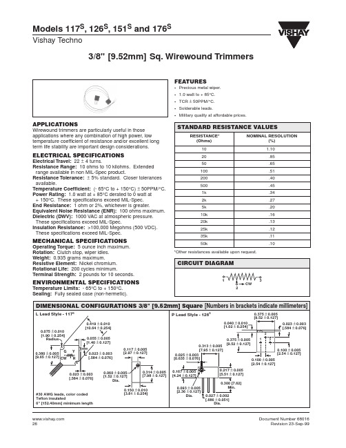
0.300 [7.62] Min. 0.027 ± 0.002 [.686 ± 0.051] Dia. 0.100 ± 0.005 [2.54 ± 0.127] 0.100 ± 0.005 [2.54 ± .127] 0.139 ± 0.005 [3.53 ± 0.127]
0.100 ± 0.005 [2.54 ± 0.127]
ENVIRONMENTAL PERFORMANCE
TEST1 Power Conditioning Thermal Shock Low Temperature Storage Low Temperature Operation High Temperature Exposure Moisture Resistance Resistance to Soldering Heat Shock Vibration Rotational Life Load Life
0.060 ± 0.005 [1.52 ± 0.127] Dia.
0.314 ± 0.005 [7.98 ± 0.127]
0.217 ± 0.005 [5.51 ± 0.127] 0.300 [7.62] Min. 0.027 ± 0.002 [.686 ± 0.051] Dia.
#30 AWG leads, color coded Teflon insulated 6" [152.40mm] minimum length
Vishay Techno
DIMENSIONAL CONFIGURATIONS 3/8" [9.52mm] Square [Numbers in brackets indicate millimeters]
W Lead Style - 151S
26m贴片晶振规格书
26m贴片晶振规格书英文回答:The specification sheet for a 26m SMD crystaloscillator is an important document that provides detailed information about the product. It includes various parameters, characteristics, and performance specifications that are necessary for selecting and using the crystal oscillator in electronic circuits.One of the key specifications mentioned in the sheet is the frequency stability. This refers to how well thecrystal oscillator maintains its frequency output over time and under different environmental conditions. For example, a 26m SMD crystal oscillator may have a frequency stability of ±10 ppm (parts per million), which means that the actual frequency may vary by up to 10 ppm from the nominal frequency of 26 MHz. This specification is crucial for applications where precise timing is required, such as in telecommunications or industrial control systems.Another important specification is the operating temperature range. This indicates the range of temperatures within which the crystal oscillator can operate reliably. For instance, a 26m SMD crystal oscillator may have an operating temperature range of -40°C to +85°C. It is important to ensure that the crystal oscillator is used within this specified temperature range to maintain its performance and reliability.The specification sheet also provides information about the load capacitance. This refers to the external capacitance required to be connected to the crystal oscillator for proper operation. For example, a 26m SMD crystal oscillator may require a load capacitance of 18 pF. It is important to consider this specification when designing the circuit and selecting the appropriate external components.Furthermore, the specification sheet may includedetails about the supply voltage and current consumption of the crystal oscillator. This information is important forpower management and ensuring that the crystal oscillatoris operated within the specified voltage range. For example, a 26m SMD crystal oscillator may have a supply voltagerange of 2.7V to 5.5V and a typical current consumption of 10 mA.In addition to these technical specifications, the specification sheet may also provide information about the package size, pin configuration, and recommended soldering profile for the 26m SMD crystal oscillator. These details are important for the mechanical and electrical integration of the crystal oscillator into the circuit board.中文回答:26m贴片晶振的规格书是一份重要的文件,提供了有关该产品的详细信息。
MS3106A-16S-1S中文资料
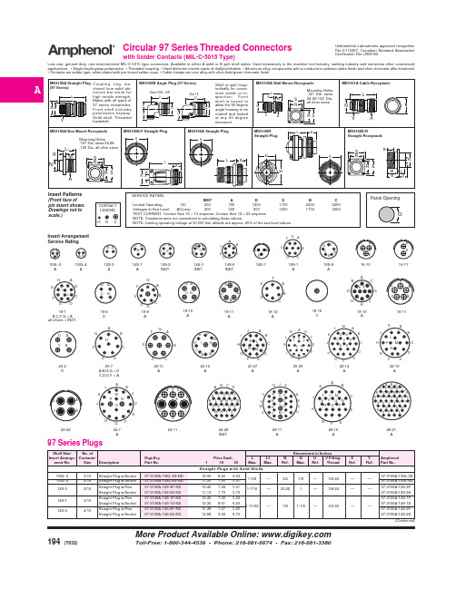
20-16
9/2#12, Straight Plug w/Pins 9/7#16 Straight Plug w/Socket
20-27
14/16 Straight Plug w/Pins Straight Plug w/Socket
20-29
17/16 Straight Plug w/Pins Straight Plug w/Socket
Low cost, general duty, non-environmental MIL-C-5015 type connectors. Available in either A solid or B split shell styles. Used extensively in the machine tool industry, welding industry and numerous other commercial applications. • Single key/keyway polarization • Threaded coupling • Hard dielectric inserts made of diallyl-phthalate • Aluminum alloy components with a conductive cadmium plate finish and olive chromate after-treatment • Contacts are solder type, silver plated with pre-tinned solder cups • Cable clamps are zinc alloy with olive drab/green chromate finish
18-12
BA3126N资料
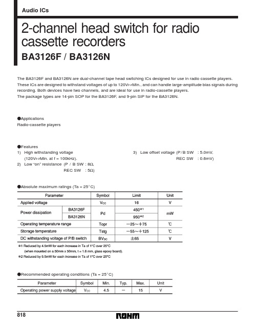
BA3126F / BA3126N
(2) REC mode When the control pin voltage goes above 3.9V, the P / B SW goes off and the REC SW goes on to put the IC into record mode. In this mode, the recording signal from REC amplifier is transmitted to the head via the P / B SW.
(4) Recommended operating power supply voltage range Operation of the basic functions of the application example circuit are guaranteed if operated within the stipulated power supply voltage and ambient temperature ranges. We cannot guarantee the ratings for the electrical characteristics, but they will not change radically if the circuit is operated within the stipulated power supply voltage and ambient temperature ranges. (5) Transient characteristics during power supply switching When the power is switched on and of in P / B mode (control pin low), a transient current may flow from the P / B SW to the REC SW. If the head is in contact with the tape, and this current flows into the head, the frequency component will be recorded as a pop sound on the tape. Pay due consideration to the power supply on / off timing and the head position relationship. (6) Playback-to-recording switching timing If a large-amplitude signal from the bias oscillator is applied when the P / B SW is on, the P / B switch may latch if there is excessive current from the bias oscillator. If this happens, the P / B SW will not switch off when the control pin is driven high, and the IC will not enter REC mode. Design the timing so that when the IC is switched from playback to recording mode, the P / B SW goes off before the large-amplitude signal from the bias oscillator is applied to the P / B SW.
XK3126中文说明书

都② 可设定为限内或限外报警,当比较值高于上限值时,▲ 标记亮,当比较值低于下限值时,▼ 标记亮,在上下
成
限值之间时,
标记亮。如果为限内报警
标
记亮时同时发出警示音,如果为限外报警 ▲ 或 ▼
标记亮时同时发出警示音。
注:当前秤量小于 10d(d—显示分度值)时检重功能无效。同时
设置内外报警时,上限必需大于下限值,否则检重功能错误。
司 次外部校正确认值,当前使用计重单位为 kg/lb 时校正单 公 位为当前使用计重单位)为止,往秤盘上加载与校正重量
值等量的标准砝码,直到发出蜂鸣音并返回到计重状态,
校正结束。
限
50.00有 GROSS
子 b) 在校正过程中可以按列印退出校正。
kg
电 c) 如果要修改校正重量值,当校正数据出现时,按 检重 键 进入修改状态,按扣重/背光移位,按 累加/单位键修改 逊 数据,修改完成后按确认键确认修改,数据闪烁加载砝
P 100.00 司 % 公 Stable Mode
限 b) 此时卸下样品,放上待称物品,即显示当前物品相对于样
有 品重量的百分比(加载 5kg)。如图:
子
5电0.00 %
逊 Stable
瑞 c) 退出百分比模式 在此状态下按 功能 键可退回到计重状态。同时清除采样
普 数据。 都d) 百分状态下的百分比、重量的转换
司 4. 避免在高温(40℃以上)、低温(0℃以下)、高湿度(85%RH) 公 以上的环境中使用。
5. 切勿直接称量酸、碱、盐等腐蚀性的物品;称液体物品时应放入
限 专制的容器里,应避免流入秤体内以免造成元件损坏;避免用强 有 溶剂(如苯,硝基类油漆)擦洗表面,以免导致表面及按键线路
