Viney_6e_PowerPoint__ch03
虚拟仪器 labview 课件PPT 第七章 字符串与文件IO
第七章 字符串与文件I/O
子字符串的替换(Replace ⑥ 子字符串的替换(Replace Substring) 能实现字符串的插入、删除、替换和抽取, 能实现字符串的插入、删除、替换和抽取,节 点图标及接口: 点图标及接口:
第七章 字符串与文件I/O
第七章 字符串与文件I/O
⑦ 字符串的查找与替换(Search and Replace String) 能实现字符串的查找与替换,节点图标及接口: 能实现字符串的查找与替换,节点图标及接口:
第七章 字符串与文件I/O
滚动位置(Scroll ② 滚动位置(Scroll Position) 移动文本,其输入为无符号整数N 移动文本,其输入为无符号整数N。使文本的 行处于字符串控件的顶端。 第N行处于字符串控件的顶端。动态改变节点的 输入,可以使文本滚动显示。 输入,可以使文本滚动显示。
第七章 字符串与文件I/O
(3)Update Value While Typing 该选项有效后, 该选项有效后,输入或更改每一个字符的结 果都会同步地传递到端口上, 果都会同步地传递到端口上,即此时是逐个字符 更新到程序端口上的。缺省情况下( 更新到程序端口上的。缺省情况下(此项未选 ),控件只在字符串输入结束后 回车), 控件只在字符串输入结束后( ),才 中),控件只在字符串输入结束后(回车),才 会把结果传递给其它端口。 会把结果传递给其它端口。
第七章 字符串与文件I/O
2. 字符串控件菜单 在前面板字符串对象的右键弹出菜单中, 在前面板字符串对象的右键弹出菜单中,可以调 整字符串控件的显示模式和外观。 整字符串控件的显示模式和外观。
第七章 字符串与文件I/O
(1)显示模式 在字符串设置菜单中,共有4中模式: 在字符串设置菜单中,共有4中模式: a) Normal Display 是控件的缺省模式,在该模式下, 是控件的缺省模式,在该模式下,显示所 有可显示的输入字符。 有可显示的输入字符。有些字符在该模式下 是不可显示的,如制表符、ESC等 是不可显示的,如制表符、ESC等 “\ Display:控制码显示 b) “\”Codes Display:控制码显示 在该模式下, 在该模式下, 把“\”及其后接的字符理 解为格式化字符。 解为格式化字符。这种模式可显示一些不可见 字符。具体格式及含义见下表: 字符。具体格式及含义见下表:
Motor Driver HAT 用户手册说明书
Motor Driver HAT用户手册产品概述Motor Driver HAT是专为树莓派控制电机而设计的,使用I2C接口控制,适用于驱动小车电机。
特点⚫基于树莓派接口设计,适用于Raspberry Pi Zero/Zero W/Zero WH/2B/3B/3B+⚫I2C接口控制,通过改变5个地址跳线可以同时接多达32个模块⚫板载PCA9685芯片,可输出12位硬件PWM控制电机转速⚫板载TB6612FNG双H桥电机驱动芯片,工作高效,不易发热⚫板载5V稳压芯片,输出可达3A电流,可通过VIN端子接入电池供电⚫预留I2C控制接口,方便接入其他主控板⚫提供完善的配套资料手册(提供BCM2835、wiringPi与python例程)产品参数供电电压:6V ~ 12V(VIN端子)逻辑电压: 3.3VPWM驱动芯片:PCA9685PWM芯片接口:I2C电机驱动芯片:TBA6612FNG产品尺寸:65mm x 30mm固定孔通径: 3.0mm接口说明模块实物图如下:硬件资源硬件上实际上由三部分构成:电源、PWM、电机驱动电源输入端采用MP1584稳压芯片,该芯片支持4.5V到28V的宽电压输入,输出电流达3A。
虽然芯片支持最高28V的输入,但是由于给电机的工作电压也由VIN_USER供给,实际上输入电压最好保持在6-12V.MP1584稳压芯片输出5V,这个5V用于给树莓派供电,然后5V再通过RT9193-33转成3.3V电平,该电平给PWM、电机驱动这两部分提供逻辑电压PWM由于树莓派硬件PWM只有一个引脚GPIO.1,而且,虽然wiringPi库与python都有软件PWM,但是会占用部分CPU资源,因此本模块采用PCA9685芯片,该芯片使用I2C控制,可输出16路12位分辨率的PWM,可控制输出频率40HZ-1000HZ。
操作简单,只需要给芯片控制对应寄存器的值,即可一直输出PWM信号。
根据上面的原理图,我们可以看出LED0-LED5为控制电机驱动芯片管脚。
ICP DAS I-7188E 系列与 I-7000 模块安装指南说明书
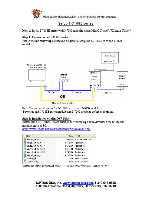
Setup I-7188E seriesHow to install I-7188E series with I-7000 modules using MiniOS7 and VXComm Utility? Step 1: Connection of I-7188E seriesPlease use the following connection diagram to setup the I-7188E series and I-7000 modules.Fig : Connection diagram for I-7188E series with I-7000 module.Power up the I-7188E series module and I-7000 modules before proceeding.Step 2: Installation of MiniOS7 UtilityInstall MiniOS7 Utility. Please click on the following link to download the utility and install it on your PC./documents/zips/miniOS7.zipInstall the latest version of MiniOS7 in this case “minios7_utility_v321”Double click on the MiniOS7 Utility Icon on the desktop to open the Utility.Step 3 : Search the I-7188E series module in MiniOS7 UtilityThe following picture shows the main screen of the MiniOS 7 Utlity.Click on the drop down menu on the “connection” and click “Search”The search function should automatically find the I-7188E series.In case the I-7188E series is not found automatically then put the module in “Init” mode. Steps to switch module into “Init” mode:•Jumper a wire across INIT* and GND terminal.•Power cycle the module.The search function would bring up the module as below.Steps to switch module back to normal mode:•Remove the jumper wire from Init* terminal•Power cycle the moduleStep 4: Change IP Address, Subnet Mask and Gateway:Click on the “IP Setting” and change the parameters like IP Address, Subnet Mask and Gateway. (Please check with your companies IT support before changing the IP Address)Step 5: Connect to the I-7188E series moduleAfter the IP Address, Subnet Mask and Gateway is set correctly. Perform the Search function again. Press “Connect”.The connection is verified by checking the serial cable on the next screen.If the serial cable on top right is fluorescent then the module is connected.Step 6: Install the VXComm UtilityPlease click the following link to download the VXComm Utility and the Users Manual. /vxcomm.phpFor Win 98: /pub/cd/8000cd/napdos/driver/vxcomm_driver/9x/For Win 2K/XP: /pub/cd/8000cd/napdos/driver/vxcomm_driver/2k/ Manual: /pub/cd/8000cd/napdos/driver/vxcomm_driver/manual/ Step 7: Launch the VXComm UtilityAfter installing the VXComm Utility, run the Utility using the following path from Windows.The main page of the VXComm Utility is as follows:Use the VXComm Utility Manual to add I-7188E series as the VXComm Server. The following screen should be obtained once you configure I-7188E series module in VXComm. (I-7065 is connected on COM 2 of I-7188E3) Virtual COM 8 in this example.Step 8: Testing the devices connected on COM ports of I-7188E seriesThis is the verification step to confirm that I-7188E series has been configured and setup correctly. This can be done by pulling up the devices connected to the COM ports of I-7188E series in their respective Utilities.Eg: In our example we have I-7065 connected to COM 2 of I-7188E3 (Virtual COM8) Hence we would use DCON Utility to pull up the I-7065 module information.Select the COM 8 in DCON UtilitySearch for the connected device (I-7065). Following is the screen that comes up.。
LabVIEW FPGA SPARTAN3E Starter Kit 实验指南说明书

Lab 1:Implementing a Boolean function in LabVIEW FPGA on the Xilinx SPARTAN-3E BoardKeywords: LabVIEW, LabVIEW FPGA, Xilinx SPARTAN3E Starter Kit, Implementing a Boolean Function.IntroductionWelcome to Lab1 in the serie of programming a SPARTAN3E Starter Kit by use of LabVIEW FPGA. These labs are created by Vincent Claes. If you encounter problems using this labs or want some advice/consultancy on LabVIEW and especially LabVIEW FPGA you can always contact the author.These labs are free to use however to show respect to the author please email him when you use them with your contact details (feedback is also welcome).Contact Information:Vincent Claes**********************/in/vincentclaesSoftware Requirements:•LabVIEW 8.5 or above•LabVIEW 8.5 FPGA module•XUP Spartan3E starter board: download for free from: https:///nicif/us/infolvfpgaxilsprtn/content.xhtmlHardware Requirements:•Xilinx Spartan3E Starter kit:/products/devkits/HW-SPAR3E-SK-US-G.htm•User manual:/support/documentation/boards_and_kits/ug230.pdfGetting StartedWhen you want to use this labs you have to setup your board. This labs are written for the Xilinx SPARTAN3E Starter Kit soit is quite interesting to read the user manual of the board. Be sure to plug in the USB cable, plug in the Power cord and Switch the board on before starting the lab.Step 1: Starting LabVIEWThe first step is to start the National Instruments LabVIEW 8.5 environment.Step 2: Create a LabVIEWprojectAfter we have started the LabVIEW environment we get the following screen:We have to create an Empty Project where we will add the Xilinx Spartan3E starter board on as a hardware target. In a future lab I will explain how we can create a HOST vi (this is a LabVIEW application that runs on a desktop PC) that communicates with a LabVIEW FPGA vi.Step 3: Add the Spartan3E board as a hardware targetThe next screen shows the Project Explorer view of the Empty Project that we just created.Now we have to add the Spartan3E starter board as a Hardware target. For this we do a “right click” on “My Computer” in the Project Explorer view. We select “New” and then “Targets and Devices”.In the screen that now appears we have to select the XUP starter board. Select “New target or device”.A list of “Targets and Devices” will be shown. You have to scroll down till the end and select “Spartan-3E Starter board” from the “Xilinx university Program” map.This will add the FPGA Target to the Project Explorer view. You see this target is placed under “My Computer”.Step 4: Adding FPGA I/OThe next step we make is adding “FPGA I/O’s” that we will use in this project to the Project Explorer view. For this you have to “right click” the FPGA Target you added in Step 3. Select “New” “FPGA I/O”.The next screen will appearOn the left side of this screen you see all the resources that are available on the Spartan-3E board. To add FPGA I/O to the project you have to select it in the left window and press the “Add” button. Now the FPGA I/O that you wanted to add has to show up in the window on the right side. For this project you have to add SW0, SW1 and LED0 to the project.If we go back to the “Project Explorer” view we see the FPGA I/O that we have added. With this I/O we will implement an Exclusive-OR function.Step 5: Creation of the FPGA VI The next step is the creation of a hardware program that runs on the Xilinx Spartan-3E hardware target.For this we do again a “right mouse click” on the FPGA target in the “Project Explorer” view. Select “New” VI. Be sure that you have right clicked the FPGA target and not “My Computer” because otherwise you will be creating a vi that runs not in Hardware (on the FPGA) but on your computer.This step will open the Front Panel and Block Diagram of the FPGA VI you just started creating. The code we will be implementing is an Exclusive-OR function. The view I always use in LabVIEW is the “tile left and right” view. You can select this by going to “Window” and then selecting “Tile Left and Right”. We you did all the steps right you have to see in the left corner of either the Front Panel or Block Diagram the name of the vi you created with /FPGA target behind it. This shows that the vi you are creating is aimed at the FPGA target.For now have a look at the “Functions Palette” which you can see when you click in the “Block Diagram” on “View” and then “Functions Palette”. You see that the available functions are different. You see “FPGA I/O”, “Memory & Fifo” and “FPGA Math & Analysis”. Those are specially for using on FPGA targets.Click in the Functions Palette on “FPGA I/O”.Place 2 I/O Nodes on the Block Diagram of the LabVIEW FPGA vi.Now do a “right mouse click” on one of the I/O Nodes. Select “Select FPGA I/O” then “Slide Switches” then “SW0”.You should see that the I/O node is filled with a green “SW0” label. The color green is standing for a Boolean variable. This is correct since a slider switch can only have the value of true or false.This project will be using 2 slider switches so we have to add another FPGA I/O. For this do a right click on the FPGA I/O you just filled with SW0. Select “Add Element”.The following is the screen you should have now:Try now to fill the I/O Item yourself with SW1. Try also to fill the I/O Node that is empty with LED0. This is done by right mouse clicking it then selecting “Select FPGA I/O”. In the option of “Select FPGA I/O” you see only the resources you added in the “Project Explorer” view to the project.The following screen will be created:Now we will as an example implement an exclusive-OR Boolean function into the FPGA. From the “Functions Palette” select “Programming” “Boolean” and look for the “Exclusive Or” function. Place this one on the Block diagram.Wire the “SW1” and “SW0” FPGA I/O to the Exclusive-OR inputs. Wire the output of the function to “LED0”.Your code has to look like this:When you implement the function like presented above the function will run only once. We would like to implement it that it runs continuously. For this we place a “While Loop” around it and we wire a Boolean “False constant” to the “stop condition” of this loop. This you normally don’t do on a PC because this will put your PC in a never ending loop. The “While Loop” you find on the “Functions Palette”.Now it is time to save your vi that you created for the FPGA. You do this by selecting “New” “Save As” in either the “Front Panel” or the “Block Diagram”.The name I usually use is FPGA_VI for the vi running on the FPGA.In “Project Explorer” you should see the followingIt is also a good idea to save the project file for this select in the “Project Explorer” “New” then “Save As”.I did use the name Lab1_BooleanLogicStep 5: Running the FPGA VIThis step is where we created the vi for. We designed it to run on an target. For starting the executing of this vi we have to press the “Run” arrow on either the “Block Diagram” or on the “Front Panel”.The first step LabVIEW does is “Generating Intermediate Files”. This files will be send to the Xilinx Synthesis Tools. But this is not important for us as application developers.In this step you see that LabVIEW is starting the “Compile Server”. This “Compile Server” can also be executed on another “more powerful” machine that is in your network (for this please see the information on the NI website.When the “Bitstream generation is complete” message appears and the server status is set to “Idle…” the Xilinx synthesis tools have done their job.You get a “Successful Compile Report” where you can see the implementation details of your code. You have to Press “Ok”.After you have pressed the “Ok” button your VI starts running on the FPGA target. It is indicated on your screen by the black “Run” arrow.Try to play with the switches SW0 and SW1 on the Spartan3E starter board you will see they have an XOR function; the led LD0 will be on when one of those switches is turned on.The problem with this implementation is that when you stop the VI the function is erased on the LabVIEW FPGA board. If you don’t want this effect you can download this VI to the FLASH of the Xilinx Spartan3E starter board (see next step).Step 6: Implementing the LabVIEW VI into FlashFor implementing your VI into the Flash on the Spartan3E Starter board you have to do some things. The first thing is setting the option of “Run when loaded to FPGA” on. For this you have to go to “Project Explorer”. Then “Right Mouse click” on your FPGA target. Select the “Properties” option.In this screen you see the option “Run when loaded to FPGA”. Make sure you select this option. Then press the “OK” button.We must recompile the VI because we made a change. Do this by going to the “Project Explorer” view. Click with the “Right Mouse button” on the FPGA VI you have created for thisproject. Select the “Compile” option.You will see that there are some previous explained steps executed. When the “Successful Compile Report” shows up youhave to press the “OK” button. Now we will download it to theFlash. For this you have to go to the “Project Explorer” view and do a “right mouse click” on the FPGA VI you created. Then choosing the “Download VI to Flash Memory” option will start downloading it to the Spartan-3E starter board flash.When this box appears the LabVIEW FPGA VI is downloaded to the Flash.Now you can pull out the USB cable out of the Xilinx Spartan3E board and press the PROG button on this board. You will see that the function is implemented in it.Enjoy.Vincent ClaesXIOS Hogeschool LimburgDepartment of Industrial Sciences and TechnologyUniversitaire Campus - Agoralaan – Gebouw HB-3590 DiepenbeekBelgium*********************tel.: +32 11 26 00 39fax: +32 11 26 00 54mobile: +32 478 35 38 49。
华仪 6700系列 交流电源使用说明书

5.1 RS-232 界面........................................................................................................................34 5.2 GPIB 界面......................................................................................35 5.3 指令表................................................................................................................................35
4.2.1 记忆组选择键(Memory) ..........................................................................................10 4.2.2 步骤选择键(Step) .....................................................................................................10 4.2.3 测试参数键(Edit)...................................................................................................... 11 4.2.4 测试结果显示键(Results) ........................................................................................23 4.2.5 系统参数键(System) ................................................................................................24 4.3 测试说明............................................................................................................................32 4.3.1 AUTO RUN 设定为”PROGRAM” ...........................................................................32 4.3.2 AUTO RUN 设定为”MANUAL”..............................................................................32 4.3.3 测试画面之功能键说明...........................................................................................33
PowerPoint 2003超酷技巧大联播

PowerPoint 2003超酷技巧大联播责任编辑:李乾仑作者:郭伟2006-02-15【内容导航】∙第1页:在PowerPoint中插入Flash动画∙第2页:在PowerPoint中制作彩色公式∙第3页:PowerPoint插入MP3音乐∙第4页:让剪贴画灵活改变颜色【IT168 实用技巧】微软的PowerPoint简单易用,但要真正用好它,还是需要不少技巧的,比如你知道怎样在幻灯片中插入flash动画吗?怎样插入mp3?怎样让剪贴画和公式换颜色等等?这篇文章我们就大家提供几个超酷技巧。
(相关文章:新奇!PowerPoint也玩刻录)1、在PowerPoint中插入Flash 动画打开PowerPoint,单击“视图→工具栏→控件工具箱”命令,这将打开ActiveX控件工具箱面板,如图一所示:图1工具箱的最后一个按钮是“其他控件”的按钮,单击该按钮,打开系统上已安装的ActiveX控制的清单,选中“Shokewave Flash Object”选中后光标将变成十字形。
如图二所示:图2用十字标在幻灯片上拖出一块Flash电影播放的屏幕空间。
Flash电影能随意占用屏幕上的任意大小或位置。
如图三所示:图3拖好Flash窗口后,右击该窗口。
在弹出的菜单里的选择“属性”项,在Flas 的页面属性对话框中的 Movie 框中键入SWF 格式电影文件的URL或路径。
如果SWF电影文件在PowerPoint文件的同一目录下,则键入SWF文件名即可,如图四所示。
幻灯播放时,Flash可以自动播放。
图五是插入动画后的截图,图六是播放时的截图。
图4图5图62、在PowerPoint中制作彩色公式首先利用公式编辑器制作好公式,然后返回PowerPoint编辑状态。
将公式拖至目标位置放置,然后拖动尺寸控点将公式的大小调整至最佳尺寸。
单击“视图→工具栏→图片”命令,打开“图片”工具栏,单击“图片”工具栏中的“图片重新着色”按钮,打开“图片重新着色”对话框,选中“颜色”复选框,单击“更改为”下拉箭头,弹出下拉列表,单击“其它颜色”选项,从调色板中选择所需要的颜色,如“红色”,单击两次“确定”按钮返回到PowerPoint 编辑区中,可看到公式颜色由黑色变为红色了。
Moxa CP-104UL 104JU Series PComm Lite Release Note

Utility for CP-104UL/104JU Series (PComm Lite) Release Notes Supported Operating SystemsNotesChangesApplicable ProductsBugs Fixed• Different versions of PComm Lite 2000 can be installed on the same PC.• Performance Analyzer can store previous configurations of the COM port list.• PComm Terminal users can set history depth in ANSI and VT100 mode.• PComm Terminal could not locate system file ws2_32.dll in Windows 2000 and Windows XP.• In the Send Pattern function, an individual port cannot be stopped but all ports can be stopped simultaneously.EnhancementsWindows 2000, Windows 7, Windows Server 2003, Windows Server 2008, Windows Server 2008 R2,Windows Vista, Windows XPUSB-to-Serial Converters, Multiport Serial Boards, Serial Device Servers• Added byte transmit/receive counter in PComm Terminal.• PComm Terminal supports pasting clipboard content to terminal.New FeaturesN/A• Terminal Emulator: Supports all serial products, including non-Moxa products.• Diagnostic Utility: Supports Moxa Multiport Serial Boards.• Monitor Utility: Supports Moxa Multiport Serial Boards.• Performance Analyzer: Supports Moxa Multiport Serial Boards, UPort Series, and NPort Series.• PComm Library: Supports all serial products, including non-Moxa products.Supported Operating SystemsNotesChangesApplicable ProductsBugs Fixed• ncludes VC project example code for PComm library • Read method using RX_CHAR event.• Supports opening multiple COM ports.• Log files can be stored in a specified path/link.N/AEnhancementsWindows 2000, Windows 7, Windows Server 2003, Windows Server 2008, Windows Server 2008 R2,Windows Vista, Windows XPUSB-to-Serial Converters, Multiport Serial Boards, Serial Device Servers• Supports Windows 2008/2008 R2 (x86/x64).• Supports HEX code display for dumb mode.• Supports linear baud rate configuration.• Supports send pattern for multiple COM ports.• Supports data file pattern.• Supports interval time between sending two patterns.• Supports network communication: TCP Server/Client, UDP.• Supports auto line wrap.• Supports customizing terminal size.• Supports DTR/DSR flow control configuration.• Supports Performance Analyzer.New FeaturesN/A• Terminal Emulator: Supports all serial products, including non-Moxa products.• Diagnostic Utility: Supports Moxa Multiport Serial Boards.• Monitor Utility: Supports Moxa Multiport Serial Boards.• Performance Analyzer: Supports Moxa Multiport Serial Boards, UPort Series, and NPort Series.• PComm Library: Supports all serial products, including non-Moxa products.Supported Operating SystemsNotesChangesApplicable ProductsBugs Fixed• VT100 added "DEL" key support.• Modified all online help to HTML format.• PComm Lite supports up to COM1024.• Updated PComm.dll to fix ASCII tx causing VB program to hang if tx is held by CTS flow control.EnhancementsWindows 2000, Windows 7, Windows Server 2003, Windows Vista, Windows XPUSB-to-Serial Converters, Multiport Serial Boards, Serial Device Servers• Supports Windows Vista/7.New FeaturesN/A• Terminal Emulator: Supports all serial products, including non-Moxa products.• Diagnostic Utility: Supports Moxa Multiport Serial Boards.• Monitor Utility: Supports Moxa Multiport Serial Boards.• Performance Analyzer: Supports Moxa Multiport Serial Boards, UPort Series, and NPort Series.• PComm Library: Supports all serial products, including non-Moxa products.Supported Operating SystemsNotesChangesApplicable ProductsBugs Fixed• PComm Terminal display performance.• PComm Terminal status bar display problem.• PComm Terminal display problem with Moxa UC Series/EtherDevice/W2004 console.EnhancementsWindows 2000, Windows Server 2003, Windows XPUSB-to-Serial Converters, Multiport Serial Boards, Serial Device Servers• Utilities support Moxa MSB x64 driver.• PComm Library supports Windows x64 Edition (AMD64, EM64T). For cross development, x86 & x64library will both be installed.New FeaturesN/A• Terminal Emulator: Supports all serial products, including non-Moxa products.• Diagnostic Utility: Supports Moxa Multiport Serial Boards.• Monitor Utility: Supports Moxa Multiport Serial Boards.• Performance Analyzer: Supports Moxa Multiport Serial Boards, UPort Series, and NPort Series.• PComm Library: Supports all serial products, including non-Moxa products.。
西门子技术问题总汇

文档标题
如何设置模拟量输入模板 SM 431-7KF00的温度补偿? 如何解决 SIMATIC BATCH 的 IL43基本设备上 hotfix 安装的问题? 如果通过 PCS7 V6.1 SP1 DVD 单独安装 SIMATIC BATCH Report 需要注意哪些设置? 为什么冗余模拟量输出模块的每个通道只有一半电流输出? 使用WinCC/Web Navigator V6.1 SP1需要什么样的操作系统和软件? 是否 COM PROFIBUS 可以使用所有版本的 GSD 文件? 如何在 WinCC flexible 中组态与S7 控制器的 Profinet 连接? 如何在操作面板上设定定时器时间, 同时如何输出定时器的剩余时间? 数据块初始值与实际值的含义 如何通过窗口对象滚动条步进调节过程值参数? 使用 SINAUT ST7 向电子邮箱接受方发送文本信息 SMS 需要做何设置? 可以使用CPU317-2PN/DP替代在iMap中组态的CPU315-2PN/DP吗? 什么情况下插入C-PLUG卡或者C-PLUG有什么作用? 通过一台PC,可以使用哪种方式访问与IWLAN/PB link PNIO或IE/PB link PNIO连接的PROFIBUS设备? 当在SINAUT网络中使用4线变压器应该注意哪些设置? 在 SINAUT 网络中,使用MD3拨号调制解调器作为专线调制解调器时,要进行哪些设置? 如何安装 DCF77 天线, 当选择 DCF77 天线时需要注意什么? 使用SINAUT ST7向传真机发送文本信息时,需要进行哪些设置? 在 SINAUT 项目中发送短消息必须进行哪些特殊服务的设置? 如何在S7-300 PN CPU和CP343-1之间建立一个open TCP 通讯连接,以及如何进行数据交换? 如何在两个S7-300 PN CPU之间建立一个open TCP 通讯连接,以及如何进行数据交换? 哪些控制系统可以成功与SINAUT ST7一起使用? 使用“零-Modem”电缆连接 TIM 模块应该注意什么? 当用 SINAUT 诊断工具的ST1协议进行诊断时,为什么TIM的状态不能显示? TIM 3V-IE 和 TIM 3V-IE Advanced 模块在以太网上通信时使用哪个端口号? 如何对没有接入网络的S7-200CPU编程? 掉电后,LOGO!的程序会丢失吗? 从 PCS7 V6.1 起,为什么没有分配任何 hierarchy (PH) 的 测量点(变量)通过编译不能在OS中自动创建相应的变量? 在SFC中,如何实现从一个 Sequencer 跳出后回到另一个 Sequencer 的某个固定位置并继续执行? 如何实现过程变量的平均值归档? 存储文件的目标路径和备份可选路径有何作用? WinCC变量归档中如何实现采集周期小于500ms的变量归档? 为什么在 OS 上会显示如下信息“时间跳变通知-永久切换为从站模式”? 在西门子A&D产品支持网站是否可以下载关于ET200M的手册? 在S7-400上怎样安装冗余电源? UDT改变后怎样更新使用UDT产生的数据块。 为什么在FB块中使用OUT变量赋值被调用FB块的IN变量时出现错误信息34:4469? 如何查看4-mation导入-导出错误 不能正确引导8212-1QU IBM/Lenovo M52 ThinkCentre 实时趋势更新缓慢的原因 如何保存变量名字典CSV文件的格式
LabVIEW的ActiveX实验--调用powerpoint(精)

一台 一套
3.Excel
4.PowerPoint
一套
一套
实验原理
LabVIEW提供了强大的外部程序接口,包括DLL、CIN、ActiveX、 Matlab等。通过DLL,可以方便调用C、VC、VB等编程语言及 Windows自带的API函数;通过ActiveX,方便调用外部程序、控件 等。
利用LabVIEW调用Excel和PowerPoint提供的ActiveX来操作Excel 和PowerPoint
实验步骤2---调用PowerPoint
((1) 在函数面板→互连接口→ActiveX, 选择“打开自动化”,将其放在程序框 图的合适位置。 (2)在“打开自动化”上单击鼠标右键, 在弹出的菜单中选择“选择ActiveX类→ 浏览”,出现如图4-5所示的对话框,从 类型库中选择Microsoft PowerPoint 11.0 Object Library Version 2.8,在对象 框中,选择仅显示可创建的对象,然后 选择Application (PowerPoint.Application.11),单击 “确定”,就可以完成Automation Refnum控件与PowerPoint Application 的连接。
LabVIEW培训
团队:晏 凯 韩 君 肖迎春 张胜宇
LabVIEW的ActiveX实验
实验目的 实验器材 实验原理 实验步骤
实验目的
1.了解LabVIEW的外部程序接口 2.掌握在LabVIEW中调用ActiveX的方法
013软件
实验步骤2---调用PowerPoint
实验步骤2---调用PowerPoint
实验步骤2---调用PowerPoint
LabVIEW DSP模块版本1.0说明书
RELEASE NOTESLabVIEW DSP Module™Version 1.0ContentsIntroduction (1)LabVIEW Embedded Edition (2)System Requirements (3)Installation (3)DSP Module Documentation (4)Where to Go for Support (5)IntroductionThe LabVIEW DSP Module supports the design, implementation, andanalysis of digital signal processor-based algorithms and systems. You canapply the concepts of digital signal processing techniques, such as spectralanalysis or filtering, with the DSP Module and one of the followingevaluation boards:•National Instruments SPEEDY-33•Texas Instruments 6711 DSK•Spectrum Digital 6713 DSKThe DSP Module adds features and VIs to LabVIEW that focus on creatingsignal processing applications that run on embedded digital signalprocessors (DSPs). You can focus on concepts and results rather than ontedious implementation details.For the ClassroomThe DSP Module provides students with a positive hands-on DSPexperience that increases their enthusiasm for the subject matter. Studentsuse graphical programming methods to learn DSP fundamentals and todevelop applications for DSP hardware without having to write any C,assembly, or script source. Students benefit from the simplicity andusability of the DSP Module while still being exposed to leading-edgeindustry DSP design tools.For Industry ApplicationsBy using a graphical programming environment for DSP applications, youcan greatly reduce the design and development time while creating moremaintainable and reusable code. Graphical programming for DSPs is moreintuitive than C or assembly so the learning curve is smaller, which allowsyou to expand into new application areas.Application Areas and AnalysisThe DSP Module addresses engineering-related challenges in which DSPsare widely used. In addition to using the DSP Module to teach fundamentalDSP concepts running in real-time on DSP hardware, you also can use theDSP Module to build communication systems, music and speechapplications, and to design complex motor control applications. Additionalapplication areas include the following:•Communication•Modulation and demodulation•FIR (finite impulse response) and IIR (infinite impulse response)filtering•Digital LMS (least-mean-square) filtering•Speech processing and analysis•Noise analysis•Cross correlation•Information processingLabVIEW Embedded EditionThe DSP Module uses LabVIEW 7.1 Embedded Edition, which is a specialedition of LabVIEW 7.1 that installs in a separate directory and does notinterfere with LabVIEW 7.1 Base, Full, or Professional developmentsystems.LabVIEW DSP Module Release System RequirementsThe DSP Module has the following requirements:• A desktop computer with Windows 2000/XP•LabVIEW 7.1 Embedded Edition (included)•One of the following evaluation boards:–National Instruments SPEEDY-33–Texas Instruments 6711 DSK–Spectrum Digital 6713 DSKRefer to the LabVIEW Release Notes, available by selectingStart»Programs»National Instruments»LabVIEW 7.1 EmbeddedEdition»LabVIEW Manuals and opening relnote.pdf, for standardLabVIEW development system requirements.InstallationComplete the following steps to install the DSP Module. After you installthe DSP Module, you must install the driver(s) for your DSP target.1.Log on as an administrator or as a user with administrator privileges.2.Insert the LabVIEW DSP Module CD and follow the instructions thatappear on the screen.Installing the DriversYou must install the appropriate driver for the DSP target. You can find thedrivers in the following locations:•SPEEDY-33—labview embedded\resource\LabVIEWTargets\EmbeddedDSP\SPEEDY33\USB driver•Texas Instruments 6711 DSK—Refer to the Setting Up the TexasInstruments 6711 DSK Target document, available by selectingStart»Programs»National Instruments»LabVIEW 7.1 Embedded Edition»LabVIEW Manuals andopening DSP_6711dsk_setup.pdf, for information about setting upthe 6711 DSK target.•Spectrum Digital 6713 DSK—Refer to the 6713 DSK documentationfrom Spectrum Digital for information about installing the drivers.© National Instruments Corporation3LabVIEW DSP Module Release NotesSetting Up the HardwareRefer to the documentation that came with your DSP hardware forinformation about setting up and configuring the hardware. You can use thedefault configuration for the DSP Module.(6711 DSK Only) Refer to the Setting Up the Texas Instruments 6711 DSKTarget document, available by selecting Start»Programs»National Instruments»LabVIEW 7.1 Embedded Edition»LabVIEWManuals and opening DSP_6711dsk_setup.pdf, for information aboutsetting up the 6711 DSK target.DSP Module DocumentationThe DSP Module includes the following documentation in addition to thisdocument:•VI reference for the VIs the DSP Module adds to LabVIEW isavailable in the LabVIEW Help, available by selecting Help»VI,Function, & How-To Help. In the Contents tab of the LabVIEWHelp, expand the VI and Function Reference book. The DSP ModuleVI reference is in the DSP Module VIs book.•Information about how creating, building, and downloading a DSP VIto a DSP target differs from creating VIs for desktop Windows isavailable in the LabVIEW Help. In the Contents tab of the LabVIEWHelp, expand the DSP Module book.•The Getting Started with the LabVIEW DSP Module manual, availableby selecting Start»Programs»National Instruments»LabVIEW 7.1Embedded Edition»LabVIEW Manuals and openingDSP_Getting_Started.pdf, contains a tutorial that walks youthrough creating, building, downloading, and running DSP VIs.•The readme file, available by selecting Start»Programs»NationalInstruments»LabVIEW 7.1 Embedded Edition»Readme andopening readme_DSP.html, contains known issues.•Examples are available in labview embedded\examples\EmbeddedDSP and can help you get started creating DSP VIs.•The Getting Started with LabVIEW manual, available by selectingStart»Programs»National Instruments»LabVIEW 7.1 EmbeddedEdition»LabVIEW Manuals and opening gtstrtlv.pdf, containsexercises to teach you basic LabVIEW concepts.LabVIEW DSP Module Release Where to Go for SupportThe National Instruments Web site is your complete resource for technicalsupport. At /support you have access to everything fromtroubleshooting and application development self-help resources to emailand phone assistance from NI Application Engineers.National Instruments corporate headquarters is located at11500North Mopac Expressway, Austin, Texas, 78759-3504.National Instruments also has offices located around the world to helpaddress your support needs. For telephone support in the United States,create your service request at /support and follow the callinginstructions or dial 5127958248. For telephone support outside the UnitedStates, contact your local branch office:Australia1800300800, Austria4306624579900,Belgium32027570020, Brazil551132623599,Canada8004333488, China862165557838,Czech Republic420224235774, Denmark4545762600,Finland3850972572511, France330148142424,Germany490897413130, India918051190000,Israel972036393737, Italy3902413091, Japan81354722970,Korea820234513400,Lebanon96101332828,Malaysia1800887710, Mexico018000100793,Netherlands310348433466, New Zealand0800553322,Norway47066907660, Poland48223390150,Portugal351210311210, Russia70957836851,Singapore180********, Slovenia38634254200,South Africa270118058197, Spain34916400085,Sweden460858789500, Switzerland41562005151,Taiwan8860223772222, Thailand6629927519,United Kingdom4401635523545© National Instruments Corporation5LabVIEW DSP Module Release NotesNational Instruments, NI, , and LabVIEW are trademarks of National Instruments Corporation.Refer to the Terms of Use section on /legal for more information about NationalInstruments trademarks. Other product and company names mentioned herein are trademarks or tradenames of their respective companies. For patents covering National Instruments products, refer to theappropriate location: Help»Patents in your software, the patents.txt file on your CD, or/patents.© 2005 National Instruments Corporation. All rights reserved.371298A-01Apr05。
CH03 元件功能说明1-17_简
第三章组件功能说明开始设计应用前,为了让使用者了解Screen Editor系统中每一个组件有其特有的功能,以因应现场各种不同的需要,以下将依序介绍说明各种组件。
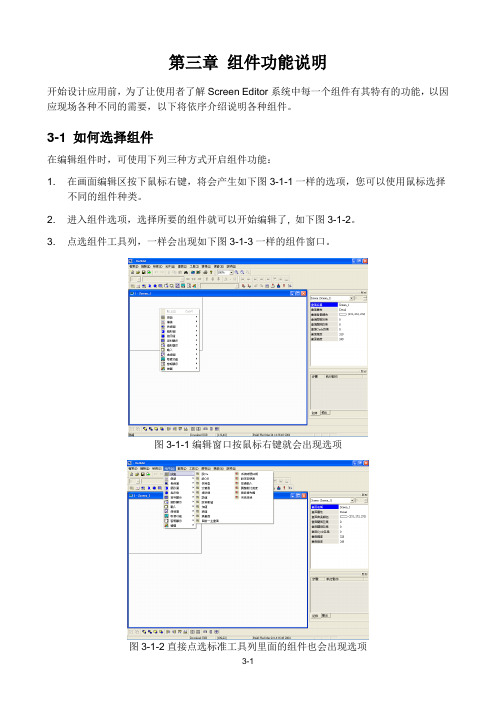
3-1 如何选择组件在编辑组件时,可使用下列三种方式开启组件功能:1. 在画面编辑区按下鼠标右键,将会产生如下图3-1-1一样的选项,您可以使用鼠标选择不同的组件种类。
2. 进入组件选项,选择所要的组件就可以开始编辑了, 如下图3-1-2。
3. 点选组件工具列,一样会出现如下图3-1-3一样的组件窗口。
图3-1-1编辑窗口按鼠标右键就会出现选项图3-1-2直接点选标准工具列里面的组件也会出现选项图3-1-3直接点选组件工具列使用鼠标左键选择欲使用之组件种类后,再使用鼠标按住左键,拖曳出组件范围即能建立一新组件如下图3-1-4所示。
图3-1-4选好后按住鼠标左键拖曳出范围放开后即可组件建立3-2 按钮组件图3-2-1一般按钮组件功能选项表格3-2-1一般按钮功能触摸此按钮,人机马上送出信号给PLC 相对应之接点ON 或OFF 。
按钮共有四类可选择:一、设ON 按钮;二、设OFF 按钮;三、交替型按钮;四、保持型按钮。
图3-2-2按钮功能组件属性以下将对按钮组件中所使用之属性加以说明:选择联机中内部存储器或已联机的内存地址,将内容写入或读取指定内存地址。
使用者可依软件所提供之组件型式与组件使用前景颜色作选择如下图(Invisible :隐藏式按钮)。
按钮组件型式编辑 ON 、OFF 宏,编辑方法请参考 第四章。
使用者可依Windows 所提供之文字大小、字型与颜色功能,设定该组件文字显示型态。
选择此组件状态是否闪烁,闪烁间隔时间可在设定模块参数的其它选项中设定(闪烁颜色为前景色直接反向)。
使用者可依图形库所支持之图形选择丰富画面,编辑方法请参考第二章。
利用本属性可直接修改组件特性,而不必重新建立组件如下图。
按钮组件特性设ON按钮:按一次该接点设为ON,手放开或再按仍为ON。
LabVIEW 7教程ppt课件

的资源管理器就是用树形控件来显示文件目录 的。
§1 字符串
表格控件举例
〔表格例如.vi〕
§1 字符串
3 字符串函数
§1 字符串
字符串函数举例
〔字符串函数例如.vi〕
§1 字符串
字符串函数举例
数据数组/电子表格字符串转换函数例如
§3 簇
error in 和error out簇
对于系统错误,code都有预先的定义,可 以通过选择Help->Explain Error…翻开错 误解释框来查找该错误代码的更详细的解释。
练习
利用簇模拟汽车控 制,如右图所示, 控制面板可以对显 示面板中的参量进 展控制。油门控制 转速,转速=油门 *100,档位控制时 速,时速=档位*40, 油量随VI运行时间 减少。
簇控件
常量簇§Βιβλιοθήκη 簇LabVIEW中使用簇可以为编程带来以下的便 ①利把。子程序框图中不同位置,不同数据类型的多个数
据攒在一起,减少了连线的混乱。 ② 子程序有多个不同数据类型的参数输入输出时,把
它们攒成一个簇可以减少连接板上端口的数量。
③ 某些控件和函数必需要簇这种数据类型的参数。
注意:簇的成员可以是任意的数据类型,但是必须同时 都是控制件或同时都是显示件。
〔字符串函数例如2.vi〕
§2 数组
数组:数组控件与数组函数
数组控件
§2 数组
1 数组控件
注意:可以是数字、字符、布尔量等数组!
§2 数组
数组之间的算术运算
LabVIEW一个非常大的优势就是它可以根据输入 数据的类型判断算子的运算方法,即自动实现多态
EV03安装调试指导手册

惠州市亿能电子有限公司
AMP 编号
功能定义
1 整车电源正,常火 K30
2 充电机 12V/24V+
3 钥匙 ACC 档启动信号
4 从板供电电源正极输出
5 整车电源地
6 从板供电电源负极输出
7 总正继电器信号负输入
8 总负继电器信号负输入
9 预充电继电器信号负输入
10 加热继电器信号负输入
12
2. 系统安装及设置
2.1 安装流程 检查物料是否 齐全
安装电压采集线束
检测/确认采集 电压是否正常
安装温度采集线束
惠州市亿能电子有限公司
A
连接系统电源线
检查所有线束连接 牢固、可靠。
系统上电,检测 与仪表或监控 通讯是否 OK
系统上 12V 电, 通过监控软件 再次确认电压、 温度是否正常。
06 接第 7 节电池负极
Байду номын сангаас
07 接第 8 节电池负极
00 02 04 06 08 10 12 01 03 05 07 09 11
08 接第 9 节电池负极 09 接第10节电池负极 10 接第 11 节电池负极
11 接第 12 节电池负极
从出线端看
12 接第 12 节电池正极
13 空
14 空
15 空
和 N 个从控模块组成(一般情况 N≤4),适用于≤240 串的锂离子电池系统 的保护和管理和电池系统总成高压控制。依据不同的控制策略,可广泛应用 于纯电动轿车、物流车和混合动力轿车和大巴领域。
从控模块一般安装在电池箱里,主要功能是测量该箱串联电芯电压(EV03 分别有最多检测 12S、24S、36S、48S、60S 五种规格的从控盒)、温度,本 箱电池一致性判断、电压均衡、风机控制以及本箱电池的累积充放电容量等, 并响应主控模块的命令,将电池的信息定期返回主控模块。
莫加(Moxa)MiiNePort E系列串口到以太网嵌入式模块说明书

P/N: 1802000012013 *1802000012013*MiiNePort E Series Quick Installation GuideVersion 1.0, November 2019Technical Support Contact Information/supportMoxa Americas:Toll-free: 1-888-669-2872 Tel: 1-714-528-6777 Fax: 1-714-528-6778 Moxa China (Shanghai office): Toll-free: 800-820-5036 Tel: +86-21-5258-9955 Fax: +86-21-5258-5505 Moxa Europe:Tel: +49-89-3 70 03 99-0 Fax: +49-89-3 70 03 99-99 Moxa Asia-Pacific:Tel: +886-2-8919-1230 Fax: +886-2-8919-1231 Moxa India:Tel: +91-80-4172-9088 Fax: +91-80-4132-10452019 Moxa Inc. All rights reserved.OverviewThe Moxa MiiNePort E series of serial-to-Ethernet embedded modules comes with four models: two standard operating temperature models (MiiNePort E, MiiNePort E-H) and two wide operating temperature models (MiiNePort E-T, MiiNePort E-H-T). Moxa provides a starter kit for each MiiNePort E series module; each starter kit contains an evaluation board that can be used to evaluate the modules and to develop your own application. The following table lists the model names of all MiiNePort E series modules, along with the model names of the corresponding starter kits.Available Modules•MiiNePort E1: Embedded device server for TTL devices, drop-in module, 10/100M with RJ45 connector, 50 bps to 230.4 Kbpsbaudrate, 0 to 55°C operating temperature•MiiNePort E1-T: Embedded device server for TTL devices, drop-in module, 10/100M with RJ45 connector, 50 bps to 230.4 Kbpsbaudrate, -40°C to 85°C operating temperature•MiiNePort E1-H: Embedded device server for TTL devices, drop-in module, 10/100M with RJ45 connector, 50 bps to 921.6 Kbpsbaudrate, 0 to 55°C operating temperature•MiiNePort E1-H-T: Embedded device server for TTL devices, drop-in module, 10/100M with RJ45 connector, 50 bps to 921.6 Kbpsbaudrate, -40 to 85°C operating temperature•MiiNePort E2: Embedded device server for TTL devices, drop-in module, 10/100M without RJ45 connector, 50 bps to 230.4 Kbpsbaudrate, 0 to 55°C operating temperature•MiiNePort E2-T: Embedded device server for TTL devices, drop-in module, 10/100M without RJ45 connector, 50 bps to 230.4 Kbpsbaudrate, -40 to 85°C operating temperature•MiiNePort E2-H: Embedded device server for TTL devices, drop-in module, 10/100M without RJ45 connector, 50 bps to 921.6 Kbpsbaudrate, 0 to 55°C operating temperature•MiiNePort E2-H-T: Embedded device server for TTL devices, drop-in module, 10/100M without RJ45 connector, 50 bps to 921.6 Kbps baudrate, -40 to 85°C operating temperature•MiiNePort E3: Embedded device server for TTL devices, pin-header module, 10/100M with RJ45 connector, 50 bps to 230.4Kbps baudrate, 0 to 55°C operating temperature•MiiNePort E3-T: Embedded device server for TTL devices, pin-header module, 10/100M with RJ45 connector, 50 bps to 230.4Kbps baudrate, -40 to 85°C operating temperature•MiiNePort E3-H: Embedded device server for TTL devices, pin-header module, 10/100M with RJ45 connector, 50 bps to 921.6Kbps baudrate, 0 to 55°C operating temperature•MiiNePort E3-H-T: Embedded device server for TTL devices, pin-header module, 10/100M with RJ45 connector, 50 bps to 921.6Kbps baudrate, -40 to 85°C operating temperatureAvailable Starter Kits•MiiNePort E1-ST: Starter kit for the MiiNePort E1 Series, module included•MiiNePort E1-H-ST: Starter kit for the MiiNePort E1-H Series, module included•MiiNePort E2-ST: Starter kit for the MiiNePort E2 Series, module included•MiiNePort E2-H-ST: Starter kit for the MiiNePort E2-H Series, module included•MiiNePort E3-ST: Starter kit for the MiiNePort E3 Series, module included•MiiNePort E3-H-ST: Starter kit for the MiiNePort E3-H Series, module includedPackage ChecklistEach MiiNePort E Series starter kit package contains the following items:• 1 MiiNePort E Series module• 1 MiiNePort E Series evaluation board• 1 universal power adapter• 2 power cords• 1 null modem serial cable• 1 cross-over Ethernet cable• 1 product warranty booklet• 2 flat cables (MiiNePort E3 Series only)• 1 pack of screw and spacer (MiiNePort E3 Series only)•Quick installation guide (print)•Warranty cardNOTE Please notify your sales representative if any of the above items are missing or damaged.Hardware Installation ProcedureFollow these steps to prepare the module and evaluation board for testing and application development.STEP 1: Plug the MiiNePort E module into the sockets on the top of the evaluation board.STEP 2: Connect the 12 to 48 VDC power line with the evaluation board’s power jack.STEP 3: Switch on the power switchSTEP 4: Use an RJ45 Ethernet cable to connect the MiiNePort E module to an Ethernet network.STEP 5: Use the serial data cable to connect the evaluation board to a serial device.Software Utility Installation ProcedureUse the following installation procedure for each MiiNePort E model: Software InstallationFor software installation, download the relevant utilities from Moxa's website: https:///en/support1.Start the Device Search Utility (DSU) setup program to beginthe installation. When the Welcome window opens, click Next.2.Click Install to install program files in the default directory.3.The Installing window reports the progress of the installation.4.Click Finish to complete the installation.Module Configuration1.Start the DSU program.2.Select the Search function from the function icons.3.After the search is finished, all MiiNePort E modules that were foundwill be shown in the search window. If you locate more than onemodule connected to this network, refer to the MAC address on the module(s) to determine the modules you wish to configure.4.Double-click on the MiiNePort E module you wish to configure; yourweb browser will be activated with the MiiNePort E’s web console.5.The default IP address of the MiiNePort E is 192.168.127.254, andthe default login credentials:username: adminpassword: moxa6.Refer to Chapter 7 of the MiiNePort E Series User’s Manual foradditional configuration instructions.Evaluation Board LayoutE1 SeriesNumber Description1 MiiNePort E2 Module Location2 Ethernet RJ45 Connector3 Serial Interface Jumper4 Power Switch5 Power Jack6 Power and Ready LED7 DB9 Male Connector8 Serial Port Status LED9 Digital IO Terminal Block10 Digital Output LED11 Digital Input/Output Mode12 Digital Input Switch13 Circuit PadNumber Description1 PoE Pin2 MiiNePort E3 Module Location3 Serial Interface Jumper4 Power Switch5 Power Jack6 Power & Ready LED7 DB9 Male Connector8 Serial Port Status LED9 Digital IO Terminal Block10 Digital Output LED11 Digital Input/Output Mode12 Digital Input Switch13 Circuit PadPin AssignmentE1 SeriesSerial Signal Pins (MiiNePort E1 Series Modules)Pin Function 1 GND 2 VCC 3 Reset 4 Data Out 5 Data In 6 Ready/RTS a 7 Reset to Default b 8 CTS ca. Pin 6 can be configured as Ready/RTS (RequesttoSend), Ready/DO,or RS-485 Tx Enabled (the default it Ready/RTS).b. Pin 7 can be configured as Reset to Default, DIO, DTR, or RS-485Tx Enabled (the default is Reset to Default). c. Pin 8 can be configured as CTS (CleartoSend), DI, or DSR (thedefault is CTS). E2 SeriesThe bottom view of the MiiNePort E2 Series ModuleJP1PinSignal Name Function1 Ethernet Tx+ Ethernet Transmit Data+2 Ethernet Tx- Ethernet Transmit Data-3 Ethernet Rx+ Ethernet Receive Data+4 Ethernet Rx- Ethernet Receive Data- JP2Pin Signal Name Function1 100M LED Ethernet 100M LED2 10M LED Ethernet 10M LED3 LRXD Receive Serial Data4 LTXD Transmit Serial Data5 LDCDData Carrier Detect 6 RS485_EN RS-485 Enable 7 LRTS Request To Send8 LDTR Data Terminal Ready 9 LDSR Data Set Ready 10 LCTSClear To SendJP3Pin Signal Name Function1 DIO0 Programmable Input/Output2 DIO1 Programmable Input/Output3 DIO2 Programmable Input/Output4 DIO3 Programmable Input/Output5 Reserved N/A6 Reserved N/A7 SW Reset Reset To Factory Default8 GND Circuit Ground9 Ready LED System is Ready10 VCC Power SupplyE3 SeriesThe bottom view of the MiiNePort E3 Series ModuleEthernet Pins (JP2)Pin Signal Name Function1 Reserve N/A2 Reserve N/A3 Reserve N/A4 Reserve N/A5 PoE signal pair 1 PoE power from Tx signal6 PoE spare pair 1 PoE power from RJ45 4, 5 pin7 PoE signal pair 2 PoE power from Rx signal8 PoE spare pair 2 PoE power from RJ45 7, 7 pinSerial Pins and Power Pins (JP4)Pin Signal Name Function1 Serial Rx Receive Serial Data2 Ready LED System is Ready3 Serial Tx Transmit Serial Data4 GPIO Programmable I/O, DIO05 DCD Receive Line Signal Detector6 GPIO Programmable I/O, DIO27 RS485_EN0 RS-485 Enabled8 GPIO Programmable I/O, DIO39 RTS Request to Send10 GPIO Programmable I/O, DIO111 DTR Data Terminal Ready12 Reserve N/APin Signal Name Function13 DSR Data Set Ready 14 Reserve N/A15 CTSClear to Send16 SW_Reset Reset to Factory Default 17 Reserve N/A 18 Reserve N/A19 GND Circuit Ground 20 VCC Power SupplyEthernet Port PinsRJ45Pin Signal 1 Tx+ 2 Tx- 3 Rx+ 6Rx-Evaluation Board Serial PortDB9 MalePinRS-232RS-485-2W 1 DCD – 2 RxD – 3 TxD D+ 4 DTR D- 5 GND GND 6 DSR – 7 RTS – 8 CTS – 9– –CertificationThis product complies with Chinese RoHS (Restriction of Hazardous Substances) regulations for Electronic Information Products.。
LabVIEW Embedded Development Module 1.0 用户指南说明书
RELEASE NOTESLabVIEW Embedded™Development ModuleVersion 1.0ContentsIntroduction (1)Prerequisites (3)LabVIEW Embedded Edition (3)System Requirements (3)Installation (3)LabVIEW Embedded Development Module Example Targets (4)Embedded Development Module Documentation (7)Where to Go for Support (7)IntroductionThe LabVIEW Embedded Development Module 1.0 enables you to portLabVIEW to new targets, including non-NI hardware. Porting LabVIEWinvolves creating a target, customizing the build process, porting therun-time environment, and customizing the editing environment for thenew target.You use utilities and modify plug-in VIs for a specific target. Customizingthe build process involves editing the VIs that control code generation,compilation, linking, and downloading. Each step of customizing the buildprocess has a set of plug-in VIs that define the behavior. The LabVIEWC Code Generator is in the LabVIEW executable, which you access with aVI server call with parameters that control the code generation settings andincludes such things as endianness, memory model, and guard coderemoval. The compilation and linking VIs script your C compiler to do thework of building the executable. You can customize the Build Settingsdialog box to add extra options to control the linker. For example, you candefine the executable format the linker generates. The download VIscontrol the transfer of the executable from the desktop PC to the embeddeddevice. The VIs for all of these steps are located in the following directory:where x is the name of the target.The run-time environment consists of code containing such things ascommunications, data manipulation, and timing functions. The run-timeenvironment is distributed in source code form. To port the run-time libraryto a new OS, you copy OS-specific folders from a similar existing OSto a new folder with the new OS name. You then modify these files towork on the new OS. The main features that require porting are serialcommunications, TCP/IP, time functions, events, threads, critical sections,and printf output. You can port the rest of the run-time code bymodifying the code in LVDefs_plat.h and LVSysIncludes.h, whichcontains macros and constants that might change when going from one OSto another.Elemental I/O Nodes provide a mechanism for portable I/O. You use theElemental I/O Device Editor to define the I/O characteristics of a board andVIs that govern the behavior of the various types of Elemental I/O Nodes,such as analog input (AI), analog output (AO), digital input (DI), digitaloutput (DO), digital bank input (DBI), digital bank output (DBO), andpulse width modulation output (PWMO) nodes. For each type of I/O, theuser creates a VI that actually performs the I/O and a VI that configures theoperation. You can implement the actual I/O VI using an Inline C Node inwhich I/O register operations are performed. The configuration VIimplements a user interface so the user can configure parameters, such aschannel, that can vary from one node to another. You can customize theLabVIEW palettes and target syntax checking for each target so users canavoid using features the target does not support. For example, you canremove the TCP/IP VIs for targets without Ethernet connectivity.Target syntax determines the supported and unsupported features for aspecific target. You receive a broken Run button when you use anunsupported feature for a target. Target syntax checking is useful whenimporting VIs that might contain unsupported features. LabVIEW loads aconfiguration file you create with a utility when you switch to a differenttarget that contains the target syntax checking for that target.LabVIEW Embedded Development Module Release Prerequisitesapplication on the target outside of LabVIEW before you attempt to port LabVIEW toa new target.To use the Embedded Development Module, you should be knowledgeableabout the following:•Your target•LabVIEW and C• A C compiler toolchain for your targetLabVIEW Embedded EditionThe Embedded Development Module uses LabVIEW 7.1 EmbeddedEdition, which is a special edition of LabVIEW 7.1 that installs in aseparate directory and does not interfere with LabVIEW 7.1 Base, Full, orProfessional development systems.System RequirementsThe Embedded Development Module has the following requirements:• A desktop computer with Windows 2000/XP•LabVIEW 7.1 Embedded Edition (included)•NI-VISA 3.1 or later (available for download at )Refer to the LabVIEW Release Notes, available by selecting Start»Programs»National Instruments»LabVIEW 7.1 Embedded Edition»LabVIEW Manuals and opening relnote.pdf, for standard LabVIEWdevelopment system requirements.InstallationComplete the following steps to install the LabVIEW EmbeddedDevelopment Module.1.Log on as an administrator or as a user with administrator privileges.2.Insert the LabVIEW 7.1 Embedded Edition CD and follow theinstructions that appear on the screen.3.Insert the LabVIEW Embedded Development Module CD and followthe instructions that appear on the screen.© National Instruments Corporation3LabVIEW Embedded Development Module Release NotesYou must activate the LabVIEW Embedded Development Module to obtainthe example targets. Refer to the Activation Instructions for NationalInstruments Software document for activation instructions. LabVIEW Embedded Development Module Example TargetsThe LabVIEW Embedded Development Module includes several exampletargets. Use the example targets as a starting point when you create newembedded targets. The target directory hierarchy is designed to allow forcode reuse. Example targets are located in the following directory: labview embedded\resource\LabVIEW Targets\EmbeddedIt is important to select an appropriate example target to use as a templatewhen you create a new embedded target. Use the target that is closest to thetarget and toolchain you are creating. If you are using a GNU C/C++-based(gcc) toolchain, you might want to use an eCos target. If you are using aVxWorks-based toolchain with different hardware, you might want to usea VxWorks subtarget.The different example targets have different implementations. When youare implementing a feature for a new embedded target, look for an existingimplementation in an existing target.The following table lists some of the implementation features for theexample targets. Use this table to find an example of a feature you areimplementing for a new target.Target Name InstrumentalDebuggingOn ChipDebugging Pre-BuiltRuntimeLibraryStaticMemoryModelMemoryMappingElementalI/OCode GenerationOnlyNo No No Yes No NoAxiom CMD565,eCos ROM ImageNo No No Yes No YesAxiom CMD565,eCos RAM ImageSerial No No Yes No Yes Unix Console TCP No Yes No No NoAxiom CMD565, VxWorks RAM Image No iSYSTEMiC3000No Yes No YesLabVIEW Embedded Development Module Release © National Instruments Corporation 5LabVIEW Embedded Development Module Release NotesExample Targets System RequirementsThe Embedded Development Module example targets have the following requirements:Axiom CMD565, VxWorks ROM ImageNoNoNoYesYesYesAxiom CMD565, VxWorks Module Serial WindRiver WTX No Yes No Yes Intel IXDP425, VxWorks RAM ImageNoWindRiver VisionICE IINoYesNoYesIntel IXDP425, VxWorks ROM ImageNo NoNo Yes No YesIntel IXDP425, VxWorks Module TCP No No Yes No Yes VxWorks Simulation TCP No No Yes No No Windows Console ApplicationTCPNoYesYesNoNoTarget NameHardware RequirementsSoftware RequirementsCode Generation Only NoneNoneAxiom CMD565, eCos ROM Image Axiom CMD-565 Development Board Cygwin 1.5.xeCos 2.0 PowerPC toolchain Axiom CMD565, eCos RAM Image Axiom CMD-565 Development Board Cygwin 1.5.xeCos 2.0 PowerPC toolchain Unix Console NoneCygwin 1.5.x with gcc package Axiom CMD565, VxWorks RAM ImageAxiom CMD-565 Development Board iSYSTEM iC3000ActiveEmulatorWind River Tornado 2.2.1 VxWorks 5.5.1 BSP for CMD565 iSYSTEM winIDEA Axiom CMD565, VxWorks ROM Image Axiom CMD-565 Development BoardWind River Tornado 2.2.1 VxWorks 5.5.1 BSP for CMD565Axiom CMD565, VxWorks ModuleAxiom CMD-565 Development BoardWind River Tornado 2.2.1 VxWorks 5.5.1 BSP for CMD565Target Name Instrumental DebuggingOn Chip DebuggingPre-Built Runtime Library Static Memory Model Memory Mapping Elemental I/OLabVIEW Embedded Development Module Release Notes Contact the respective vendors for more information about their hardware and software products.Refer to /getstart.html for information about downloading and installing eCos.The VxWorks Development Kit for the LabVIEW Embedded Development Module includes the Tornado 2.2.1 integrated development environment and evaluation run-times for VxWorks 5.5.1 for the purpose ofdemonstrating the features, performance, and capabilities of these Wind River products in association with the Labview Embedded Development Module. Refer to /alliances/eval-cd/ and click VxW for LabVIEW Embedded Development Module Evaluation Kit to receive the VxWorks Development Kit. Refer to for more information about Wind River’s Device Software Optimization products, including VxW real time operating systems and Tornado, an integrated development environment.Intel IXDP425,VxWorks RAM ImageIntel IXDP425/IXCDP1100 Development PlatformWind River visionICE II JTAG emulator Wind River Tornado 2.2.1 VxWorks 5.5.1 BSP for IXDP425Wind River visionCLICK with EST API Intel IXDP425,VxWorks ROM Image Intel IXDP425/IXCDP1100 Development Platform Wind River Tornado 2.2.1 VxWorks 5.5.1 BSP for IXDP425Intel IXDP425, VxWorks ModuleIntel IXDP425/IXCDP1100 Development PlatformWind River Tornado 2.2.1 VxWorks 5.5.1 BSP for IXDP425 TFTP ServerVxWorks Simulation NoneWind River Tornado 2.2.1 VxWorks 5.5.1(Optional) ULIP Ethernet driver Windows Console Application NoneOne of the following: Visual Studio 6.0 Visual Studio .NETVisual C ++ Toolkit 2003 version 1.01 and Core SDK PlatformTarget NameHardware Requirements Software RequirementsEmbedded Development Module DocumentationThe Embedded Development Module includes the followingdocumentation in addition to this document:•The LabVIEW Embedded Development Module Porting Guide,available by selecting Start»Programs»National Instruments»LabVIEW 7.1 Embedded Edition»LabVIEW Manuals andopening EMB_Porting_Guide.pdf, contains the information youneed to port LabVIEW to a new target. Some of this information alsois available in the LabVIEW Help, available by selecting Help»VI,Function & How-To Help.•The readme file, available by selecting Start»Programs»NationalInstruments»LabVIEW 7.1 Embedded Edition»Readme andopening readme_EMB.html, contains known issues.•The LabVIEW Help, available by selecting Help»VI, Function, &How-To Help, contains reference information about LabVIEWpalettes, menus, tools, VIs, function, and for step-by-step instructionsfor using LabVIEW features.Where to Go for SupportThe National Instruments Web site is your complete resource for technicalsupport. At /support you have access to everything fromtroubleshooting and application development self-help resources to emailand phone assistance from NI Application Engineers.National Instruments corporate headquarters is located at11500 North Mopac Expressway, Austin, Texas, 78759-3504.National Instruments also has offices located around the world to helpaddress your support needs. For telephone support in the United States,create your service request at /support and follow the callinginstructions or dial 512 795 8248. For telephone support outside the UnitedStates, contact your local branch office:Australia 1800 300 800, Austria 43 0 662 45 79 90 0,Belgium 32 0 2 757 00 20, Brazil 55 11 3262 3599,Canada 800 433 3488, China 86 21 6555 7838,Czech Republic 420 224 235 774, Denmark 45 45 76 26 00,Finland 385 0 9 725 725 11, France 33 0 1 48 14 24 24,Germany 49 0 89 741 31 30, India 91 80 51190000,Israel 972 0 3 6393737, Italy 39 02 413091, Japan 81 3 5472 2970,Korea 82 02 3451 3400, Lebanon 961 0 1 33 28 28,Malaysia 1800 887710, Mexico 01 800 010 0793,Netherlands 31 0 348 433 466, New Zealand 0800 553 322,© National Instruments Corporation7LabVIEW Embedded Development Module Release NotesNorway 47 0 66 90 76 60, Poland 48 22 3390150,Portugal 351 210 311 210, Russia 7 095 783 68 51,Singapore 1800 226 5886, Slovenia 386 3 425 4200,South Africa 27 0 11 805 8197, Spain 34 91 640 0085,Sweden 46 0 8 587 895 00, Switzerland 41 56 200 51 51,Taiwan 886 02 2377 2222, Thailand 662 992 7519,United Kingdom 44 0 1635 523545National Instruments, NI, , and LabVIEW are trademarks of National Instruments Corporation.Refer to the Terms of Use section on /legal for more information about NationalInstruments trademarks. Other product and company names mentioned herein are trademarks or tradenames of their respective companies. For patents covering National Instruments products, refer to theappropriate location: Help»Patents in your software, the patents.txt file on your CD, or/patents.© 2005 National Instruments Corporation. All rights reserved. 371439A-01Apr05。
SIMATIC ET 200SP 6ES7135-6FB00-0BA1 分析模块数据表说明书
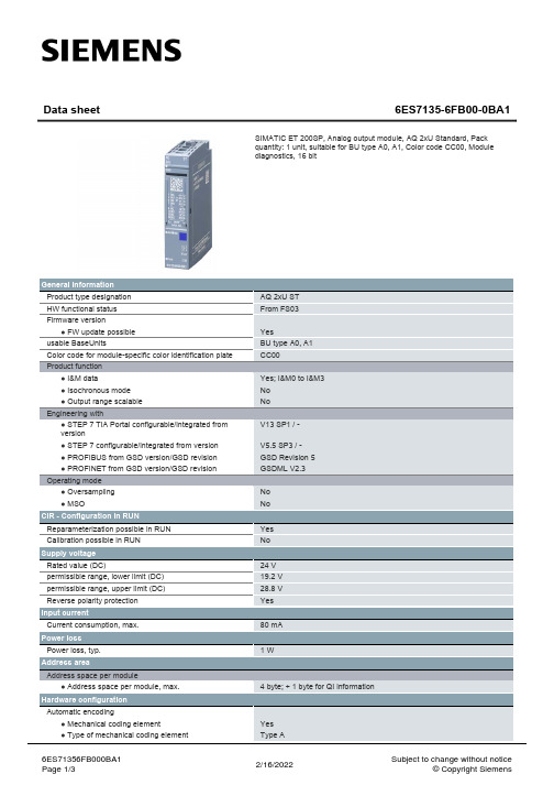
Supply voltage Rated value (DC) permissible range, lower limit (DC) permissible range, upper limit (DC) Reverse polarity protection
Crosstalk between the outputs, min.
-50 dB
Repeat accuracy in steady state at 25 °C (relative to output range), (+/-)
0.05 %
Operational error limit in overall temperature range
General information Product type designation HW functional status Firmware version ● FW update possible usable BaseUnits Color code for module-specific color identification plate Product function ● I&M data ● Isochronous mode ● Output range scalable Engineering with ● STEP 7 TIA Portal configurable/integrated from version ● STEP 7 configurable/integrated from version ● PROFIBUS from GSD version/GSD revision ● PROFINET from GSD version/GSD revision Operating mode ● Oversampling ● MSO
《中文版PowerPoint 2003实例与操作》课件 第7章

在展台浏览:该放映方式不需要专人来控制幻灯片的播放, 适合在展览会上或者会议中的某个展台上全屏放映的演示文 稿。在该放映方式下,当最后一张幻灯片放映结束时,或者 某张幻灯片已经闲置5分钟以上时,演示文稿都将自动重新 开始播放。
如果选中“循环放映,按Esc键终止”复选框,在最后一 张幻灯片放映结束后,会自动返回到第一张幻灯片继续放映。 如果选中“放映时不加旁白”复选项,则放映幻灯片时不 播放任何旁白。 如果选中“放映时不加动画”复选项,则在放映幻灯片时, 原来设定的动画效果将会失去作用,但动画效果设置参数依 然有效;一旦取消选择“放映时不加动画”复选项,则动画 效果又会出现。
单击该按钮可切换 至上一张幻灯片
单击该按钮可切 换下一张幻灯片
选择一种绘图笔,然 后将鼠标指针移至合 适的地方,按住鼠标 左键并拖动,可为幻 灯片中一些需要强调 的内容添加墨迹标记
如果在幻灯片放映视图中添 加了墨迹标记后,则当结束 放映时系统会弹出提示框, 用户可根据需要选择是否在 幻灯片中保留墨迹
本章内容提要
✓制作交互式样式文稿 ✓幻灯片放映准备 ✓放映幻灯片
7.1 制作交互式演示文稿
交互式演示文稿是指在放映幻灯片时,单击幻 灯片的某个对象便能跳转指定的幻灯片,或打开某个 文件或网页。
7.1.1 设置超链接
在PowerPoint 2003中,我们可以为幻灯片 中的任何对象,包括文本、图片、图形和图表等设 置超链接,在放映演示文稿时,单击设置了超链接 的对象,便可以跳转到超链接指向的幻灯片、文件 或网页。
演示文稿放映完毕后,可按【Esc】键结 束放映,如果想在中途终止放映,也可 按【Esc】键,或者右击幻灯片,在弹出 的快捷菜单中选择“结束放映”项
7.3.3 如何使用投影机
LabVIEWOpenVINO让你的YOLOv5在CPU上飞起来

LabVIEWOpenVINO让你的YOLOv5在CPU上飞起来重磅干货,第一时间送达本文转载自 OpenVINO 中文社区一、OpenVINO是什么OpenVINO是英特尔针对自家硬件平台开发的一套深度学习工具库,用于快速部署应用和解决方案,包含推断库,模型优化等等一系列与深度学习模型部署相关的功能。
特点:1、在边缘启用基于CNN的深度学习推理2、支持通过英特尔®Movidius™VPU在英特尔®CPU,英特尔®集成显卡,英特尔®神经计算棒2和英特尔®视觉加速器设计之间进行异构执行3、通过易于使用的计算机视觉功能库和预先优化的内核加快上市时间4、包括对计算机视觉标准(包括OpenCV *和OpenCL™)的优化调用5、通俗易懂点说想要在intel-cpu或者嵌入式上部署深度学习模型,可以考虑考虑openvino。
二、LabVIEW视觉工具包下载与配置1视觉工具包的下载与安装可在如下链接中下载OpenVINO版工具包;安装方式可参考:LabVIEW AI视觉工具包(非NI Vision)下载与安装教程中CPU用户的安装2OpenVINO toolkit下载安装下载地址:英特尔® Distribution of OpenVINO™ 工具套件1)点击Dev Tools2)选择版本,选择如下版本,并DownLoad:3)下载后,安装即可4)可以选择安装路径,具体安装可以参考官方文档:/cn/latest/openvino_docs_install_guides_installing_openvino_wi ndows.html三、模型获取openvino工作流程,和其他的部署工具都差不多,训练好模型,解析成openvino专用的.xml和.bin,随后传入Inference Engine中进行推理。
这里和上一篇博客一样可以使用export.py导出openvino 模型:python export.py --weights yolov5s.pt --include openvino 当然这里已经为大家转换好了模型,大家可以直接下载,下载链接:YOLOv5 OpenVINO IR模型四、LabVIEW+OpenVINO调用Yolov5进行实时物体识别1实现过程•dnn模块调用IR模型(模型优化器)•设置计算后台与计算目标设备(推理引擎加速)•获取输出端的LayerName•图像预处理•推理•后处理•绘制检测出的对象2程序源码3识别结果CPU模式下,使用openvino进行推理加速,实时检测推理用时仅95ms/frame,是之前加载速度的三分之一注意:1.必须安装含openvino字眼的labview工具包2. readNetFromModelOptimizer.vi中IR模型路径不可以包含中文四、附加说明:计算机环境操作系统:Windows10python:3.6及以上LabVIEW:2018及以上 64位版本视觉工具包:techforce_lib_opencv_cpu_openvino2021-1.0.0.61.vipOpenVINO:2021.4.2本文仅做学术分享,如有侵权,请联系删文。
- 1、下载文档前请自行甄别文档内容的完整性,平台不提供额外的编辑、内容补充、找答案等附加服务。
- 2、"仅部分预览"的文档,不可在线预览部分如存在完整性等问题,可反馈申请退款(可完整预览的文档不适用该条件!)。
- 3、如文档侵犯您的权益,请联系客服反馈,我们会尽快为您处理(人工客服工作时间:9:00-18:30)。
3-2
Chapter Organisation
3.1 3.2 3.3 3.4 3.5 3.6 3.7 3.8 3.9 3.10 3.11 3.12 3.13 Investment and Merchant Banks Managed Funds Cash Management Trusts Public Unit Trusts Superannuation Funds Life Insurance Offices General Insurance Offices Hedge Funds Finance Companies and General Financiers Building Societies Credit Unions Export Finance Corporations Summary
3-6
பைடு நூலகம்
Chapter Organisation
3.1 3.2 3.3 3.4 3.5 3.6 3.7 3.8 3.9 3.10 3.11 3.12 3.13 Investment and Merchant Banks Managed Funds Cash Management Trusts Public Unit Trusts Superannuation Funds Life Insurance Offices General Insurance Offices Hedge Funds Finance Companies and General Financiers Building Societies Credit Unions Export Finance Corporations Summary
• horizontal, vertical, conglomerate and hostile takeovers • synergies, economic/legal/accounting/tax considerations • analysis, valuation, negotiation, due diligence
Chapter 3
Non-bank Financial Institutions (NBFIs)
Website: .au
Copyright 2009 McGraw-Hill Australia Pty Ltd PPTs t/a Financial Institutions, Instruments and Markets 6e by Viney Slides prepared by Anthony Stanger
• Main categories of managed funds
– Common funds
Operated by trustee companies, they pool funds of beneficiaries and invest in specified asset classes Differ from unit trusts in that units are not issued E.g. solicitors offering mortgage trusts Total financial institutions assets declined from 0.9% in 1990 to 0.3% in 2008
3-7
Copyright 2009 McGraw-Hill Australia Pty Ltd PPTs t/a Financial Institutions, Instruments and Markets 6e by Viney Slides prepared by Anthony Stanger
3-4
3.1
Investment and Merchant Banks (cont.)
• Sources of funds
– Mainly securities issued into international money markets and capital markets
• Uses of funds
Copyright 2009 McGraw-Hill Australia Pty Ltd PPTs t/a Financial Institutions, Instruments and Markets 6e by Viney Slides prepared by Anthony Stanger
3.2
Managed Funds
• Investment vehicle for investing the pooled savings of individuals in various asset classes in domestic and international money and capital markets by fund managers
• Outline the financial products and services provided by NBFIs • Describe NBFIs’ principal sources and uses of funds
Copyright 2009 McGraw-Hill Australia Pty Ltd PPTs t/a Financial Institutions, Instruments and Markets 6e by Viney Slides prepared by Anthony Stanger
– Limited lending to clients, usually on short-term basis – These loans tend to be sold into the secondary market – Primarily focused on off-balance-sheet advisory services
Copyright 2009 McGraw-Hill Australia Pty Ltd PPTs t/a Financial Institutions, Instruments and Markets 6e by Viney Slides prepared by Anthony Stanger
3-5
3.1
Investment and Merchant Banks (cont.)
• Off-balance-sheet business
– Innovative products and services in provision of advice, management and funding services, generating their main income from fees, e.g.:
3-8
3.2
– – – – –
Managed Funds (cont.)
Cash management trusts (section 3.3) Public unit trusts (section 3.4) Superannuation funds (section 3.5) Statutory funds of life offices (section 3.6) Hedge funds(section 3.8)
3-1
Learning Objectives
• Understand the different types of NBFIs and their roles in the financial system
– Investment and merchant banks, managed funds, cash management and public trusts, superannuation funds, life and general insurance offices, hedge funds, finance companies and general financiers, building societies and credit unions, and export finance corporations
3-3
Copyright 2009 McGraw-Hill Australia Pty Ltd PPTs t/a Financial Institutions, Instruments and Markets 6e by Viney Slides prepared by Anthony Stanger
3.1
Investment and Merchant Banks
• Evolved under regulation • Are not authorised banks and are officially classified as ‘money market corporations’ in Australia • Share of total financial institution assets declined from 7.2% in 1990 to 2.6% in 2008 • Roles are essentially the same
Copyright 2009 McGraw-Hill Australia Pty Ltd PPTs t/a Financial Institutions, Instruments and Markets 6e by Viney Slides prepared by Anthony Stanger
