EDS-1505-04
能量分散谱仪(EDS)

能谱仪的缺点:
• (1)能量分辨率低,峰背比低。由于能谱仪的探头直 接对着样品,所以由背散射电子或X射线所激发产 生的荧光X射线信号也被同时检测到,从而使得Si(Li) 检测器检测到的特征谱线在强度提高的同时,背底 也相应提高,谱线的重叠现象严重。故仪器分辨不 同能量特征X射线的能力变差。能谱仪的能量分辨 率(130eV)比波谱仪的能量分辨率(5eV)低。 • (2)工作条件要求严格。Si(Li)探头必须始终保持在液 氦冷却的低温状态,即使是在不工作时也不能中断, 否则晶体内Li的浓度分布状态就会因扩散而变化, 导致探头功能下降甚至完全被破坏。
能量分散谱仪
EDS
能谱仪
• 能谱仪全称为能量分散谱仪(EDS). • 能谱仪的结构及工作原理: • 能谱仪是利用X 光量子的能量不同来进行元素分析的方 法,对于某一种元素的X 光量子从主量子数为n1的层上 跃迁到主量子数为n2的层上时有特定的能量ΔE=En1- En2。X 光量子的数目是作为测量样品中某元素的相对 百分含量用,即不同的X 光量子在多道分析器的不同道 址出现,而脉冲数-脉冲高度曲线在荧光屏或打印机上 显示出来,这就是X光量子的能谱曲线。 • 所谓能谱仪实际上是一些电子仪器,主要单元是半导体 探测器(一般称探头)和多道脉冲高度分析器,用以将 X光量子按能量展谱。
谢谢!
• 目前最常用的是Si(Li)X 射线能谱仪,其关键 部件是Si(Li)检测器, 即锂漂移硅固态检测 器,它实际上是一个 以Li为施主杂质的n-i-p 型二极管。
EDS-G205A-4PoE系列快速安装指南说明书

P/N: 1802002051026 *1802002051026*EDS-G205A-4PoE Series Quick Installation GuideMoxa EtherDevice SwitchVersion 4.2, January 2021Technical Support Contact Information/support2021 Moxa Inc. All rights reserved.OverviewThe EDS-G205A-4PoE series industrial Ethernet switches are rugged entry-level industrial 5-port Gigabit PoE switches for environments that fall under the pollution degree 2 category. The industrial Ethernet switches support IEEE 802.3, IEEE 802.3u, and IEEE 802.3x with10/100/1000M, full/half-duplex, MDI/MDIX auto-sensing, and IEEE 802.3af/IEEE 802.3at PoE standards.The EDS-G205A-4PoE series provides 12/24/48 VDC redundant power inputs that can be connected simultaneously to a live DC power source. The switches are available with a standard operating temperature range from 0 to 60°C, or with a wide operating temperature range from -40 to 75°C, and their IP30 metal housing makes them rugged enough for any harsh industrial environment.To provide greater versatility for use with applications from different industries, the EDS-G205A-4PoE switches also allow users to enable or disable broadcast storm protection, 802.3az, Jumbo frame, and PoE high power with DIP switches on the outer panel. The EDS-G205A-4PoE switches can be easily installed on a DIN-Rail or in distribution boxes. The DIN-Rail mounting capability and IP30 metal housing with LED indicators make the plug-and-play EDS-G205A-4PoE switches reliable and easy to use.NOTE Throughout this Hardware Installation Guide, we use EDS as an abbreviation for Moxa EtherDevice Switch:EDS = Moxa EtherDevice SwitchPackage ChecklistYour EDS is shipped with the following items. If any of these items is missing or damaged, please contact your customer service representative for assistance.•Moxa EtherDevice™ Switch•Quick Installation Guide (printed)•Warranty cardFeaturesHigh-watt Power-over-Ethernet•Up to 30 watts output per PoE port (IEEE 802.3at)•Supports PoE high power output up to 36 W•Short circuit and over-current protection•Auto detection for IEEE 802.3af and IEEE 802.3atHigh Performance Network Switching Technology•10/100BaseT(X), 1000BaseT and 100/1000BaseX (SFP)•10/100/1000M, Full/Half-Duplex, MDI/MDIX auto-sensing•IEEE 802.3/802.3u/802.3x•Store and Forward switching process type, 8k MAC address entries •10k jumbo framesRugged Design•Redundant dual 12/24/48 VDC power inputs•Operating temperature range from 0 to 60°C, or extended operating temperature of -40 to 75°C for (T) models.• IP30 metal housing• DIN-rail or panel mounting abilityEDS-G205A-4PoE Panel Layouts1. Terminal blocks for P1/P2power inputs2. Power input P1 LED3. Power input P2 LED4. PoE status LED5. 10/100/1000BaseT(X) PoEports (ports 2, 3, 4, 5) 6. TP port speed LED7. 10/100/1000BaseT(X) port(port 1)8. 100/1000BaseX SFP slot 9. Model name10. Grounding screw11. P1 power input terminalblock12. P2 power input terminalblock13. DIP switches14. Screw holes for panelmounting kit15.DIN-rail mounting kitMounting DimensionsUnit = mm (inch)DIN-Rail MountingThe aluminum DIN-rail attachment plate should already be fixed to the back panel of the EDS when you take it out of the box. If you need to reattach the DIN-rail attachment plate, make sure the stiff metal spring is situated towards the top, as shown in the figures below. STEP 1: Insert the top of the DIN-rail into the slot just below the stiff metal spring.STEP 2: The DIN-Rail attachment unit will snap into place as shown below.To remove the EDS from the DIN-rail, simply reverse Steps 1 and 2 above.Wall Mounting (optional)For some applications, you will find it convenient to mount the EDS-G205A-4PoE on a wall, as shown in the following figures. STEP 1:Remove the aluminum DIN-rail attachment plate from the EDS-G205A-4PoE’s rear panel, and then attach the wall mount plates as shown in the diagram at the right.STEP 2:Mounting the EDS-G205A-4PoE on the wall requires 4 screws and the recommended tightening torque is 3.5±0.5 (kgf cm). Use the switch, with wall mount plates attached, as a guide to mark the correct locations of the 4 screws. The heads of the screws should be less than 6.0 mm in diameter, and the shafts should be less than 3.5 mm in diameter, as shown in the figure at the right.NOTE Before tightening the screws into the wall, make sure the screwhead and shank size are suitable by inserting the screw into one of the keyhole-shaped apertures of the wall mounting plates. Do not screw the screws in completely—leave about 2 mm to allow room for sliding the wall mount panel between the wall and the screwsSTEP 3: Array Once the screws are fixed on thewall, insert the four screw headsthrough the large parts of thekeyhole-shaped apertures, and thenslide the EDS downwards, asindicated. Tighten the four screwsfor added stability.Wiring RequirementsYou should also pay attention to the following points:•Use separate paths to route wiring for power and devices. If power wiring and device wiring paths must cross, make sure the wires are perpendicular at the intersection point.NOTE: Do not run signal or communications wiring and power wiring in the same wire conduit. To avoid interference, wires with different signal characteristics should be routed separately.•You can use the type of signal transmitted through a wire to determine which wires should be kept separate. The rule of thumb is that wiring that shares similar electrical characteristics can bebundled together.•Keep input wiring and output wiring separated.•It is strongly advised that you label wiring to all devices in the system when necessary.•Please use copper conductor only.Grounding the EtherDevice SwitchGrounding and wire routing help limit the effects of noise due to electromagnetic interference (EMI). Run the ground connection from the ground screw to the grounding surface prior to connecting devices.Wiring the Redundant Power InputsThe two 2-contact terminal block connectors on the EDS’s top panel are used for the EDS’s two DC power inputs. Top and front views of the terminal block connectors are shown here.STEP 1: Array Insert the negative/positive DC wires into the V-/V+terminals.STEP 2:To keep the DC wires from pulling loose, use a smallflat-blade screwdriver to tighten the wire-clamp screws onthe front of the terminal block connector.STEP 3:Insert the plastic terminal block connector prongs into theterminal block receptor, which is located on the EDS’s toppanel.Communication ConnectionsThe EDS-G205A-4PoE switches have 4 10/100/1000Base-T(X) PoEEthernet ports for connecting PoE devices, and 1 10/100/1000BaseT portor 1 100/1000BaseX SFP slot for uplink connection. For fiber connections,a field installed optical transceiver must be UL Recognized, in the Class Icategory, and contain the following CDRH Certification Marking:‘Complies with 21CFR 1040.10 and 1040.11’.10/100/1000BaseT(X) Ethernet Port Connection10/100/1000BaseT(X) ports located on the EDS’s front panel are used toconnect to Ethernet-enabled devices. Below we show pinouts for bothMDI (NIC-type) ports and MDI-X (HUB/switch-type) ports, and also showcable wiring diagrams for straight-through and cross-over Ethernet cables.10/100BaseT(x) RJ45 PinoutsMDI Port Pinouts MDI-X Port Pinouts 8-pin RJ45Pin Signal 1 Tx+ 2 Tx- 3 Rx+ 6Rx-Pin Signal 1 Rx+ 2 Rx- 3 Tx+ 6Tx-1000BaseT RJ45 PinoutsPin MDI MDI-X 1 BI_DA+ BI_DB+ 2 BI_DA- BI_DB- 3 BI_DB+ BI_DA+ 4 BI_DC+ BI_DD+ 5 BI_DC- BI_DD- 6 BI_DB-BI_DA-7 BI_DD+BI_DC+ 8BI_DD- BI_DC-PoE Ethernet Port ConnectionPoE ports located on the EDS switch’s front panel are used to connect to PoE-enabled devices. The pinout follows the Alternative A, MDI mode of 802.3af/802.3at standards. Details are shown below. PoE Port Pinouts 8-pin RJ45Pin Power 1 V+ 2 V+ 3 V- 6 V-NOTE According to IEEE 802.3af/at standards, the PD shall be implemented to be insensitive to the polarity of the power supply and shall be able to operate per MDI mode and MDI-X mode. However, some PDs only support MDI mode or MDI-X mode only. The following figures show how to select the correct cable to connect between the PD and EDS-G205A-4PoE.RJ45 (8-pin) to RJ45 (8-pin) Straight-Through Cable WiringRJ45 (8-pin) to RJ45 (8-pin) Cross-Over Cable WiringNOTE If the PD only supports PoE MDI mode (V+, V+, V-, V- for pins 1, 2, 3, 6), choose a cross-over Ethernet cable to connect the PD and the EDS switch. If the PD only supports PoE MDI-X mode (V-, V-, V+, V+ for pins 1, 2, 3, 6), choose a straight-through Ethernet cable between the PD and the EDS switch.Redundant Power InputsBoth power inputs can be connected simultaneously to live DC power sources. If one power source fails, the other live source acts as a backup, and automatically supplies all of the EDS’s power needs.DIP Switch SettingsThe default setting for each DIP Switch is OFF. The following table explains the effect of setting the DIP Switches to the ON positions.EDS-G205A-4PoE (Copper Model)EDS-G205A-4PoE-1GSFP(SFP Model)DIP SwitchSetting DescriptionBSPONEnable broadcast storm protection OFF Disable broadcast storm protection Jumbo FrameONEnable jumbo frame function OFF Disable jumbo frame function802.3azONEnable the energy-efficient Ethernet function OFF Disable the energy-efficient Ethernet function PoE High Power ON Supports PoE high power output up to 36 W. PoE high power is activated when an 802.3af or 802.3at connection is detected.OFF Supports standard PoE power output up to 30 W 100/1G SFP (For SFP model only)ON Supports 100M SFP module OFF Supports 1000M SFP module––– (For copper model only)–Serves no function (reserved for future use)LED IndicatorsThe front panel of the EDS switches contain several LED indicators. The function of each LED is described in the following table.LED Color State DescriptionP1 AMBER OnPower is being supplied to power inputP1.OffPower is not being supplied to powerinput P1.P2 AMBER OnPower is being supplied to power inputP2.OffPower is not being supplied to powerinput P2.10/100/ 1000 AMBEROnTP port’s 10/100 Mbps or SFP port’s100 Mbps link is active.BlinkingData is being transmitted at 10/100Mbps.OffTP port’s 10/100 Mbps or SFP port’s100 Mbps link is inactive.GREENOn TP/SFP port’s 1000 Mbps link is active.BlinkingData is being transmitted at 1000Mbps.OffTP/SFP port’s 1000 Mbps link isinactive.PoE+ AMBEROnThe PoE device is connected by theIEEE 802.3af standardBlinking(1 time/s)The PoE power has been shut offbecause the power budget is too low.OffNo PoE power output or no PoEconnected PoE devicesGreenOnThe PoE device is connected by IEEE802.3at standard or PoE High Power OffNo PoE power output or no PoEconnected PoE devicesRedBlinkingPoE failure:– 1 time/s: PoE standard detectionfailure– 2 times/s: PoE current overloadOff No PoE failureAuto MDI/MDI-X ConnectionThe Auto MDI/MDI-X function allows users to connect the EDS’s10/100/1000BaseT(X) ports to any kind of Ethernet device, without needing to pay attention to the type of Ethernet cable being used for the connection. This means that you can use either a straight-through cable or cross-over cable to connect the EDS to Ethernet devices.Triple Speed Functionality and SwitchingThe Moxa EtherDevice Switch’s 10/100/1000 Mbps switched RJ45 port auto negotiates with the connected device for the fastest data transmission rate supported by both devices. All models of Moxa EtherDevice Switch are plug-and-play devices, so that software configuration is not required at installation, or during maintenance. The half/full duplex mode for the switched RJ45 ports is user dependent and changes (by auto-negotiation) to full or half duplex, depending on which transmission speed is supported by the attached device.Jumbo FrameThe EDS-G205A-4PoE series supports Ethernet jumbo frames up to 10k, which is with more than 1500 bytes of payload. This function is by default disabled and can be enabled by turning on the DIP switch labeled “Jumbo” on the top cover. This is commonly used for large packet size applications such as video surveillance.Broadcast Storm ProtectionThe EDS-G205A-4PoE Series has a built-in algorithm for limiting the amount of broadcast packets through the switch. This function is by default disabled and can be enabled by turning on the DIP switch labeled “BSP” on the top cover. If the broadcast storm protection algorithm detects more than 2k broadcast frames per second, then the switch will be suppressed from receiving broadcast frames for a period of 2 ms to prevent any further flooding.Total Power BudgetFor the total power budget, the EDS-G205A-4PoE will provide 62 W at 12 to 17 VDC input, 120 W at 18 to 35 VDC input, and 144 W at 36 to 57 VDC input. The total power budget is the total amount of reserved PoE power based on the PoE class of the PoE device. If a newly connected PoE device causes the total reserved power to exceed the total power budget, the newly connected PoE device will be denied power.Input Voltage Total Power Budget12 VDC (12 to 17 VDC) 62 W24 VDC (18 to 35 VDC) 120 W48 VDC (36 to 57 VDC) 144 WPoE Class Reserved Power0 15.4 W1 4.0 W2 7.0 W3 15.4 W4 30 WPoE High Power ApplicationPoE High Power can be enabled by DIP switch, and supply up to 36 W of PoE power when the PSE detects an 802.3af or 802.3at connection. Refer to the table below for the power budget at different input voltages, and for the number of PoE High Power Ports supported.Input Voltage TotalPowerBudgetNumber of PoE High Power Ports12 VDC (12 to 17 VDC) 62 W Up to 1 PoE high power port (36 W) 24 VDC (18 to 35 VDC) 120 W Up to 3 PoE high power port (36 W) 48 VDC (36 to 57 VDC) 144 W Up to 4 PoE high power port (36 W) SpecificationsTechnologyStandards IEEE 802.3 for 10BaseT,IEEE 802.3u for 100BaseT(X) and 100BaseFX,IEEE 802.3ab for 1000BaseTIEEE 802.3z for 1000BaseXIEEE 802.3x for Flow ControlIEEE 802.3af for PoEIEEE 802.3at for PoE+Processing Type Store and ForwardInterfaceRJ45 Ports 10/100/1000BaseT(X) auto negotiation speed,F/H duplex mode, and auto MDI/MDI-XconnectionFiber Ports 100/1000 BaseX ports (SFP Slot)LED Indicators Power: P1, P2TP Port: 10/100/1000Fiber Port: 100/1000PoE Ports: PoE+ for Port 2, 3, 4, 5DIP Switch Broadcast Storm Protection, Jumbo Frame,802.3az, Standard PoE/PoE High Power,100/1G SFPPoETotal Power Budget 62 W @ 12 VDC (12 to 17 VDC)120 W @ 24 VDC (18 to 35 VDC)144 W @ 48 VDC (36 to 57 VDC)PoE Output Voltage 53 VDC @ 12/24/48 VDC power inputPoE Output Power 15.4 W in 802.3af,30 W in 802.3at,36 W in high power modePoE Output Current 350 mA in 802.3af,600 mA in 802.3at,720 mA in high power modeOverload CurrentProtection at PortPresentPoE Pinout Mode A: Pair 1, 2 (V+); Pair 3, 6 (V-)PowerInput Voltage 12/24/48 VDC, redundant dual inputs Operating Voltage 12 to 57 VDCRated Current 5.92 A @ 12 VDC5.65 A @ 24 VDC3.21 A @ 48 VDCPower Consumption 11.73 W without PDs’ consumption Inrush Current 17.4 A @ 24 VDC (0.1 to 1 ms) Electrical Isolation 2250 VDC to chassis for 60 sHeat Dissipation 36.4 BTU/hOverload CurrentProtection at InputPresentReverse PolarityProtectionPresentConnection 2 removable 2-contact terminal blocks Physical CharacteristicsHousing Aluminum, IP30 protection Dimensions 29 x 135 x 105 mmWeight 300 gInstallation DIN-rail mounting,Wall mounting (with optional kit) Environmental LimitsOperating Temperature Standard models: 0 to 60°C (32 to 140°F) Wide temp. models: -40 to 75°C (-40 to 167°F)Storage Temperature -40 to 85°C (-40 to 185°F)Ambient RelativeHumidity5 to 95% (non-condensing)Standards and CertificationsSafety UL 508EMC EN 55032/24EMI CISPR 32, FCC Part 15B Class AEMS IEC 61000-4-2 ESD: Contact: 6 kV; Air: 8 kVIEC 61000-4-3 RS: 80 MHz to 1 GHz: 10 V/mIEC 61000-4-4 EFT: Power: 2 kV; Signal: 2 kVIEC 61000-4-5 Surge: Power: 2 kV; Signal: 2 kVIEC 61000-4-6 CS: 10 VIEC 61000-4-8Rail Traffic EN 50121-4Shock IEC 60068-2-27Freefall IEC 60068-2-32Vibration IEC 60068-2-6WARRANTYTime 5 yearsDetails /warrantyPatent /doc/operations/Moxa_Patent_Marking.pdf。
UCS 500N5 UCS 500N7系列抗扰度综合测试仪中文手册

3.1. 前面板.........................................................................................................7 3.2. 后面板.........................................................................................................9
产品手册 - USC500 系列抗扰度综合测试
UCS 500 系列抗扰度综合测试仪
中文操作手册
总部地址: 北京市海淀区学清路 9 号汇智大厦 A 座 605 室 邮编:100085 电话:010-82732992 传真:010-82732995
南京办事处: 洪武路 359 号福鑫国际大厦东座 2507 室
7.4.1. 工厂校准 .............................................................................................. 28 7.4.2. EMTEST 仪器校准周期指导 ....................................................................... 28
8. 交付件 ............................................................................................................. 29
8.1. 基本设备 .................................................................................................... 29 8.2. 附件和选件 ................................................................................................. 29
碳点的功能化、自放热合成及其在生化药物分析中的应用研究
基金资助本论文得到国家自然科学基金:基于长程共振能量转移的生物医学成像分析基础研究(编号:21535006)的资助,在此表示衷心的感谢。
目录摘要 (I)Abstract (III)第1章论文选题依据及研究内容 (1)1.1论文选题依据 (1)1.1.1 研究意义 (1)1.1.2 研究现状 (1)1.1.2.1 碳点的分类、光致发光的起源、性质和挑战 (1)1.1.2.2 碳点的合成途径 (5)1.1.2.3 碳点在荧光分析检测领域的应用 (10)1.2研究目标、研究内容、以及拟解决的关键科学问题 (13)1.2.1 研究目标 (13)1.2.2 研究内容 (13)1.2.3 拟解决的关键科学问题 (14)1.3技术路线 (14)第2章铽掺杂碳点的一步碳化合成及其选择性的检测2,4,6-三硝基苯酚 (15)2.1前言 (15)2.2实验部分 (16)2.2.1 材料及试剂 (16)2.2.2 实验仪器 (16)2.2.3 铽掺杂碳点的合成与纯化 (16)2.2.4 TNP的荧光分析检测 (16)2.3结果与讨论 (17)2.3.1 铽掺杂碳点的合成与表征 (17)2.3.2 铽掺杂碳点的稳定性 (19)2.3.3 TNP的荧光分析检测 (20)2.3.4 水样中TNP含量的测定 (25)2.4小结 (25)第3章铽修饰碳量子点的常规水热合成及其高选择性的检测ppGpp (27)3.1前言 (27)3.2实验部分 (28)3.2.1 材料及试剂 (28)3.2.2 实验仪器 (28)3.2.3 碳量子点和铽修饰碳量子点的合成与纯化 (28)3.2.4 ppGpp的比率荧光检测 (29)3.3结果与讨论 (29)3.3.1 碳量子点的合成与表征 (29)3.3.2 铽修饰碳量子点的合成与表征 (32)3.3.3 比率荧光法检测ppGpp (32)3.4小结 (34)第4章单层石墨烯量子点的自放热合成及其高灵敏和高特异性的检测铝离子 (35)4.1前言 (35)4.2实验部分 (36)4.2.1 材料及试剂 (36)4.2.2 实验仪器 (36)4.2.3 单层石墨烯量子点的合成与纯化 (36)4.2.4 Al3+的荧光分析检测 (37)4.3结果与讨论 (37)4.3.1 单层石墨烯量子点的自催化放热合成 (37)4.3.2 单层石墨烯量子点的表征 (40)4.3.3 Al3+诱导的单层石墨烯量子点光致发光增强 (42)4.4小结 (46)第5章高光致发光碳量子点的自放热合成及其选择性的检测维生素B12 (47)5.1前言 (47)5.2实验部分 (48)5.2.1 材料及试剂 (48)5.2.2 实验仪器 (48)5.2.3 碳量子点的合成与纯化 (48)5.2.4 维生素B12的荧光分析检测 (49)5.2.5 维生素B12的固相传感 (49)5.3结果与讨论 (49)5.3.1 碳量子点的自催化放热合成 (49)5.3.2 碳量子点的表征 (53)5.3.3 碳量子点的稳定性 (54)5.3.4 维生素B12的荧光检测 (55)5.3.5 注射液中维生素B12的含量测定 (57)5.3.6 维生素B12的固相传感 (57)5.4小结 (58)第6章全文总结与展望 (59)6.1全文总结 (59)6.1.1 主要结论 (59)6.1.2 主要创新点 (60)6.2前景展望 (60)6.2.1 碳点功能化手段的开发及应用 (60)6.2.2 自放热合成在其他纳米材料领域的开发 (60)参考文献 (63)科研成果 (71)致谢 (73)碳点的功能化、自放热合成及其在生化药物分析中的应用研究专业: 药物分析学硕士研究生: 陈斌斌指导教师: 黄承志教授摘要碳点作为新类型的光致发光纳米材料,由于其优越的光稳定性、可调的光致发光、良好的生物相容性以及易于制备的特性,而被广泛应用于细胞成像、生物与化学传感、光电器件等领域。
x射线能谱仪(eds)测试相关说明
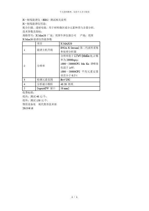
X-射线能谱仪(EDS)测试相关说明
X-射线能谱仪用途:
配合扫析。
技术参数及指标:
规格型号:X-Max50厂家:英国牛津仪器公司产地:英国
X-Max50能谱仪性能参数
项目
X-MAX50
1
能谱主机升级
INCA X-Stream2第二代波形采集和处理分析器
2
分辨率
分辨率优于127eV (MnKα处,计数率为20000cps);
1000~50000CPS Mn Ka谱峰宽化弱于1eV;
1000~50000CPS平均元素定量误差小于0.5%
3
检测元素范围
Be4-U92
4
分析最小颗粒
40-50纳米
5
SuperATW窗口
50 mm2
收费标准:
校内:测试40元/个;
校外:测试150元/个。
物资设备处现代教育技术部
2013/6/18
烷基聚氧乙烯醚硫酸钠的红外光谱

烷基聚氧乙烯醚硫酸钠的红外光谱下载温馨提示:该文档是我店铺精心编制而成,希望大家下载以后,能够帮助大家解决实际的问题。
文档下载后可定制随意修改,请根据实际需要进行相应的调整和使用,谢谢!并且,本店铺为大家提供各种各样类型的实用资料,如教育随笔、日记赏析、句子摘抄、古诗大全、经典美文、话题作文、工作总结、词语解析、文案摘录、其他资料等等,如想了解不同资料格式和写法,敬请关注!Download tips: This document is carefully compiled by theeditor.I hope that after you download them,they can help yousolve practical problems. The document can be customized andmodified after downloading,please adjust and use it according toactual needs, thank you!In addition, our shop provides you with various types ofpractical materials,such as educational essays, diaryappreciation,sentence excerpts,ancient poems,classic articles,topic composition,work summary,word parsing,copy excerpts,other materials and so on,want to know different data formats andwriting methods,please pay attention!烷基聚氧乙烯醚硫酸钠,也被称为AES(Alkyl Ethoxylate Sulfate),是一种广泛应用在洗涤剂、化妆品和个人护理产品中的表面活性剂。
毛斯产品说明书:EDS-205A 208A系列5 8端口工业级以太网交换机

The EDS-205A/208A series are 5 and 8-port industrial Ethernetswitches that support IEEE 802.3 and IEEE 802.3u/x with 10/100M full/half-duplex, MDI/MDI-X auto-sensing. The EDS-205A/208A switchesprovide 12/24/48 VDC (9.6 to 60 VDC), 18 to 30 VAC redundant powerinputs that can be connected simultaneously to live AC/DC powersources. These switches have been designed for harsh industrialenvironments, such as in maritime (DNV/GL/LR/ABS/NK), rail wayside,highway, or mobile applications(EN 50121-4/NEMA TS2/e-Mark), orhazardous locations (Class I Div. 2, ATEX Zone 2) that comply withIntroductionEDS-205A/208A SeriesSpecificationsFCC, UL, and CE standards.The EDS-205A/208A switches are available with a standard operatingtemperature range from -10 to 60°C, or with a wide operatingtemperature range from -40 to 75°C. All models are subjected toa 100% burn-in test to ensure that they fulfill the special needs ofindustrial automation control applications. In addition, theEDS-205A/208A switches have DIP switches for enabling or disablingbroadcast storm protection, providing another level of flexibility forindustrial applications.TechnologyStandards:IEEE 802.3 for 10BaseTIEEE 802.3u for 100BaseT(X) and 100BaseFXIEEE 802.3x for Flow ControlProcessing Type: Store and ForwardFlow Control: IEEE 802.3x flow control, back pressure flow controlSwitch PropertiesMAC Table Size: 1 KPacket Buffer Size: 512 KbitInterfaceFiber Ports: 100BaseFX ports (SC/ST connector, multi-mode,single-mode)RJ45 Ports: 10/100BaseT(X) auto negotiation speed, Full/Half duplexmode, and auto MDI/MDI-X connectionDIP Switches: Enable/Disable broadcast storm protectionLED Indicators: Power, 10/100M (TP port), 100M (fiber port)Power RequirementsInput Voltage: 12/24/48 VDC (9.6 to 60 VDC), 18 to 30 VAC (47 to 63Hz), redundant dual inputsInput Current:EDS-205A: 0.1 A @ 24 VEDS-205A-M/S: 0.11 A @ 24 VEDS-208A: 0.13 A @ 24 VEDS-208A-M: 0.17 A @ 24 VEDS-208A-MM/SS: 0.22 A @ 24 VOverload Current Protection: 1.1 AConnection: 1 removable 4-contact terminal blockReverse Polarity Protection: PresentPhysical CharacteristicsHousing: Aluminum, IP30 protectionDimensions:EDS-205A: 30 x 115 x 70 mm (1.18 x 4.52 x 2.76 in)EDS-208A: 50 x 115 x 70 mm (1.96 x 4.52 x 2.76 in)Weight:O rdering InformationOptional Accessories (can be purchased separately)DR-4524/75-24/120-24: 45/75/120 W DIN-Rail 24 VDC power suppliesMDR-40-24/60-24: 40/60 W DIN-Rail 24 VDC power supplies, -20 to 70°C operating temperatureWK-30: Wall mounting kit (EDS-205A series only)WK-46: Wall mounting kit (EDS-208A series only)RK-4U: 4U-high 19” rack mounting kitEMS:EN 61000-4-2 (ESD) Level 3, EN 61000-4-3 (RS) Level 3,EN 61000-4-4 (EFT) Level 3, EN 61000-4-5 (Surge) Level 3,EN 61000-4-6 (CS) Level 3, EN 61000-4-8, EN 61000-4-11Marine: DNV, GL, LR, ABS, NKWheeled Vehicles: e-Mark (E1) (EDS-208A only)Traffic Control: NEMA TS2Rail Traffic: EN 50121-4Shock: IEC 60068-2-27Freefall: IEC 60068-2-32Vibration: IEC 60068-2-6Note: Please check Moxa’s website for the most up-to-date certification status.MTBF (mean time between failures)Time:EDS-205A series: 3,040,784 hrsEDS-208A series: 2,428,212 hrsDatabase: Telcordia (Bellcore), GBWarrantyWarranty Period: 5 yearsDetails: See /warranty。
- 1、下载文档前请自行甄别文档内容的完整性,平台不提供额外的编辑、内容补充、找答案等附加服务。
- 2、"仅部分预览"的文档,不可在线预览部分如存在完整性等问题,可反馈申请退款(可完整预览的文档不适用该条件!)。
- 3、如文档侵犯您的权益,请联系客服反馈,我们会尽快为您处理(人工客服工作时间:9:00-18:30)。
EDSE ngineering,GM D AEWOO Auto & Technology.S tandardsCARBON STEEL TUBES FOR MACHINE STRUCTURAL USESEDS-M-1505ISSUED DATE: 1994. 06. 27REVISEDDATE: 2003. 02. 26VERSION: 41. SCOPEThis standard specifies carbon steel tubes for machine structural use used by GM DAEWOO Auto & Technology Company(hereinafter referred to as the "GMDAT")2. TYPE AND USE(REFERENCE)Table 1. Type and useTypeGrade SymbolUse Applications Grade 11A STKM 11AA STKM 12AB STKM 12BGrade 12C STKM 12CA STKM 13AB STKM 13BGrade 13C STKM 13CA STKM 15A Grade 15C STKM 15CA STKM 16A Grade 16C STKM 16CA STKM 19A Grade 19C STKM 19C Steel tubes used for general parts of vehicle structureSTAM 440HSTAM 470HSTAM 500H Grade HSTAM 540HTubes used for parts that yield strength matter among tubes for vehicle structureRemark:1. When designating seamless tube or welding tube, add suffix -S, -E to the end of each material symbol.2. With respect to division into A, B and C, A indicates hot worked condition or annealed condition, Bindicates slightly cold worked condition and C indicates cold worked condition or annealed condition with stress relived. However if mechanical properties are met at the corresponding chemical composition, it shall not be regulated.3. Grade H steels are manufactured by electrical resistance welding with hot rolled strips or cold rolledstrips made of killed steel.3. QUALITY3.1. Chemical compositionTable 2. Chemical CompositionUnit: wt%TypeC Si Mn P SGrade SymbolGrade 11A STKM 11A0.12 max.0.35 max.0.60 max.0.040 max.0.040 max.A STKM 12A0.20 max.0.35 max.0.60 max.0.040 max.0.040 max.Grade 12B STKM 12BC STKM 12CA STKM 13AB STKM 13BGrade 130.25 max.0.35 max.0.30¡-0.900.040 max.0.040 max.C STKM 13CA STKM 15A0.25¡-0.350.35 max.0.30¡-1.000.040 max.0.040 max.Grade 15C STKM 15CA STKM 16A0.35¡-0.450.40 max.0.40¡-1.00.040 max.0.040 max.Grade 16C STKM 16CA STKM 19A0.25 max.0.55 max. 1.50 max.0.040 max.0.040 max.Grade 19C STKM 19CSTAM 440H0.25 max.0.35 max.0.30¡-0.900.035 max.0.035 max.STAM 470HGrade HSTAM 500H0.30 max.0.35 max.0.30¡-1.00.035 max.0.035 max.STAM 540HRemark: 1. When required, Nb or V alone or Nb in combination with V may be added up to 0.15% through agreement between the manufacturer and the purchaser.2. The lower limit of carbon content may be altered by agreement between the purchaser and themanufacturer when required.3. When the purchaser requires product analysis for the tubes made of killed steel, the tolerances for thevalue given above shall be as specified in Table 2 of KS D 0228 [Product Analysis and its Tolerancesfor Steel]3.2. Mechanical propertiesTensile strength, yield strength and elongation of the tube shall be as specified in Table 3. When bending or flattening test is performed, the tube shall be free from flaws or cracks on their wall surfaces. However, the bending test shall be applied to the tube 50 mm or smaller in outside diameter instead of flattening test when especially specified by the purchaser. The tube shall be free from flaws when flaring is applied to the tube until it reaches the specified size in Table 3.Table 3. Mechanical Properties of the Tube(D : Diameter of the tube)Elongation FlatteningtestBending strength Flaring testType Tensilestrength(N/mm2)Yieldstrength(N/mm2)No. 4, 11, 12(longitudinaldirection)No. 4, 5(transversedirection)Distancebetweenflat platesBendangleInsideradiusExpandedarea bypressingSTKM 11A290 min.35 min.30 min.1/2D180¡Æ 4 D--STKM 12A340 min.175 min.35 min.30 min.2/3D90¡Æ 6 D--STKM 12B390 min.275 min.25 min.20 min.2/3D90¡Æ 6 D--STKM 12C470 min.355 min.20 min.15 min.------STKM 13A370 min.215 min.30 min.25 min.2/3D90¡Æ 6 D--STKM 13B440 min.305 min.20 min.15 min.3/4D90¡Æ 6 D--STKM 13C510 min.380 min.15 min.10 min.--------STKM 15A470 min.275 min.22 min.17 min.3/4D90¡Æ 6 D--STKM 15C580 min.430 min.12 min. 7 min.------STKM 16A510 min.325 min.20 min.15 min.7/8D90¡Æ8 D--STKM 16C620 min.460 min.12 min.7 min.--------STKM 19A490 min.315 min.23 min.18 min.7/8D90¡Æ 6 D--STKM 19C550 min.410 min.15 min.10 min.--------STAM 440H440 min.355 min.20 min.-------- 1.15 D STAM 470H470 min.410 min.18 min.-------- 1.10 D STAM 500H500 min.430 min.16 min.-------- 1.10 D STAM 540H540 min.480 min.13 min.-------- 1.05 D Remark:1. When the tensile test is carried out on No. 12 or No. 5 test piece for the tube under 8mm in wall thickness,the minimum value of elongation shall be calculated by subtracting 1.5% from the values of elongation given in Table 3 for each 1mm decrease in wall thickness and rounding off to an integer in accordance with KS A 0021[Termination Method of Numbers]2. The values of elongation in Table 3 shall not be applied to the tubes 40mm or smaller in outside diameter.However, it may be agreed upon by the purchaser and the manufacturer, when especially required.3. For electric resistance welded steel tubes, the tensile test pieces shall be taken from a portion not involvingwelded seam.3.3. WeldabilityThis tube shall be suitable for general fusion welding and resistance welding. For No 15 and 16, welding shall be carefully conducted.3.4. Surface condition3.4.1. The tube shall be practically straight and the two ends shall be at right angles to the axis of the tube.3.4.2. The tubes shall be free from defects harmful to practical use.3.4.3. The surface finish of the tubes, when especially specified, shall be agreed upon by the purchaser and the manufacturer.4. NOTESamples of materials or parts that follow this standard shall be approved by Technical Center before mass production & delivery. In the event of any modification form this standard, it is the sole responsibility of the supplier to inform the purchaser of all such modifications.Furthermore, the supplier shall submit the modified sample for reapproval by Technical Center before mass production & delivery.5. TEST5.1. All tests shall be performed at 23¡¾5¡É.5.2. Bending testThe test piece of a suitable length shall be bent around a cylinder with the bend angle and inside radius specified in Table 3, and checked for the occurrence of flaws or cracks. In the case of welded steel tubes, the weld shall be placed in the outer most part of the bent portion.5.3. Flattening testThe test piece of 50mm or over in length is placed between two flat plates and flattened by compression until the distance between the plates comes to the value specified, and it shall be checked for the occurrence of flaws or cracks on its wall surface. In the case of welded steel tubes, the weld shall be placed at right angles to the direction of compression.5.4. Flaring testThe cut piece of a suitable length shall be formed in the shape of a trumpet with a cone shaped tool of 60¡Æand the occurrence of flaws, cracks and other defects shall be checked.5.5. Test standardEDS-T-7113[Method of Tensile Test for Metallic Materials]EDS-T-7144 [Method of Test Piece Preparation for Chemical Component Analysis]KS B 0801[Tensile Test Piece for Metallic Materials] - No 4, 5, 11, 12 test piece6. CROSS INDEX (REFERENCE)Table 4. Cross indexEDS-M-1505K S ASTM OPELSTKM 11A-S STKM 11A-E QS1010 NO QS1010 TOSTKM 12B-S STKM 12B-E QS1015 NO QS1015 TOSTKM 13A-S, 13B-S STKM 13C-S STKM 13A-E, 13B-E STKM 13C-E QS1025 NO QS1025 NM QS1025 TO QS1025 TMSTKM 15A-S STKM 15C-SQS1035 NO (QS1035 NM)STKM 16A-S STKM 16C-SQS1045 NO (QS1045 NM)STKM 19A-S STKM 19C-S STKM 19A-E STKM 19C-E D 3517 A 512(QS1317 NO)(QS1317 NM)(QS1317 TO)(QS1317 TM)STAM 440H STAM 470H STAM 500H STAM 540H STAM 45H(KS D 3598)STAM 48H(KS D 3598)STAM 51H(KS D 3598)STAM 55H(KS D 3598)A 519(QS1025 TM)(QS1017 TO)7. AUTOMOTIVE RESTRICTED HAZARDOUS SUBSTANCES Materials and components of parts must comply with EDS-A-0101.。
