3D打印文献,Direct laser writing,Principles and materials for scaffold 3D printing
激光直写系统的理解

激光直写系统的理解激光直写系统(Laser Direct Writing System)是一种先进的纳米尺度制造技术,可以实现在各种材料表面直接写入微小结构或纹理。
该技术通过激光束的控制,将高能激光聚焦至纳米级别,以实现高精度的材料移除或堆积。
本文将对激光直写系统的原理、应用及未来发展进行探讨。
一、激光直写系统的原理激光直写系统基于激光器发射的高能光束实现微细结构的制造。
其原理主要包括激光聚焦、材料加工和运动控制三个步骤。
激光聚焦是实现高能光束控制的关键步骤。
激光通过透镜系统进行光束的聚焦,使激光束能够聚焦在纳米级别。
聚焦后的激光束能够获得较小的尺寸和较高的能量密度,从而实现对材料的精确加工。
材料加工过程涉及激光与材料相互作用的物理和化学变化。
激光直写系统可以根据需要选择合适的工作模式,包括材料的切割、刻蚀、沉积和改性等。
通过控制激光的照射时间、功率和聚焦点位置等参数,可以实现对材料的高精度加工。
运动控制是激光直写系统实现精确位置控制的关键。
利用精密驱动设备和高精度传感器,可以实现激光头的精确运动和位置控制。
这样,激光束可以在材料表面上准确地进行写入,并在不同位置上进行复杂的加工过程。
二、激光直写系统的应用激光直写系统具有广泛的应用前景,在多个领域都有着重要的作用。
以下是几个典型的应用领域:1. 微电子制造:激光直写系统可以用于微芯片的制造和微电子器件的加工。
通过对光刻掩膜进行精确的激光显影和刻蚀,可以实现微电子器件的制造和集成。
2. 光学器件制造:激光直写系统可以用于光学玻璃的微结构加工,包括光学波导、衍射光栅和光学薄膜等。
通过激光的高精度加工,可以实现对光学性能的优化和器件性能的提升。
3. 生物医学应用:激光直写系统在生物医学领域有着广泛的应用。
例如,可以利用激光直写系统制造微流控芯片,用于生物分析和单细胞研究;还可以制造生物组织工程的载体和植入材料,用于组织修复和再生医学。
4. 光子学器件制造:激光直写系统可以用于制造各种微小光子学器件,如光波导、光纤耦合器和光子晶体等。
3d打印应用英文文献

3d打印应用英文文献3D printing technology in the industrial product design, especially the application of digital product model manufacturing is becoming a trend and hot topic.Desktop level gradually mature and application of 3D printing devices began to promote the rise of the Global 3D printing market, Global industrial Analysis company(Global Industry Analysis Inc) research report predicts Global 3D printing market in 2018 will be $2.99 billion.Keywords:3D printing; Application; Trend13Dprinting and 3D printers3D printing and 3D printing are two entirely different concepts.3D printing is separated into different angles the picture of the red, blue two images, then the two images according to the regulation of parallax distance overprint together, using special glasses to create the 3D visual effect, or after special treatment, the picture printed directly on the special grating plate, thus rendering 3D visual effect of printing technology. And 3D printing refers to the 3D ink-jet printing technology, stacked with hierarchical processing forms, print increase step by step a material to generate a 3D entity, meet with 3D models, such as laser forming technology of manufacturing the same real 3Dobject digital manufacturing technology.3D printers, depending on the technology used by its working principle can be divided into two categories:1.13D printer based on 3D printing technology Based on 3D printing technology of 3D printer, by stored barrels out a certain amount of raw material powder, powder on processing platform is roller pushed into a thin layer, then the print head in need of forming regional jet is a kind of special glue.At this time, met the adhesive will rapidly solidified powder binder, and does not meet the adhesive powder remain loose state. After each spray layer, the processingplatform will automatically fall a bit, according to the result of computer chip cycle, until the real finished. After just remove the outer layer of the loose powder can obtain required for manufacturing three-dimensional physical.1.23D printers based on fused deposition manufacturing technology Based on fused deposition manufacturing technology of the working principle of3D printer is first in the control software of 3Dprinters into physical data generated by CAD and treated generated to support the movement of materials and thermal spray path. Then hot nozzle will be controlled by computer according to the physical section contour information inprinted planar motion on the plane, at the same time by thermoplastic filamentous material for wire agency sent to the hot shower, and after the nozzle to add heat and meltinto a liquid extrusion, and spraying in the corresponding work platform. Spray thermoplastic material on the platform after rapid cooling form the outline of a thickness of 0.1 mm wafer, forming a 3D printing section. The process cycle, load, decrease of bench height then layers of cladding forming stacked 3D printing section, ultimately achieve the desired three-dimensional object.。
3D打印 (简介、原理及技术)
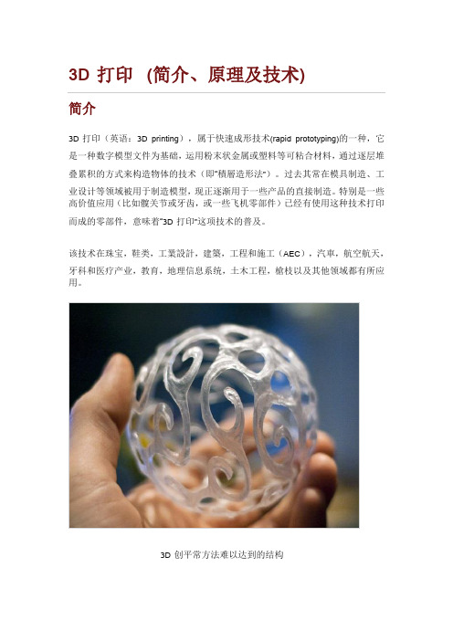
3D打印(简介、原理及技术)简介3D打印(英语:3D printing),属于快速成形技术(rapid prototyping)的一种,它是一种数字模型文件为基础,运用粉末状金属或塑料等可粘合材料,通过逐层堆叠累积的方式来构造物体的技术(即“積層造形法”)。
过去其常在模具制造、工业设计等领域被用于制造模型,现正逐渐用于一些产品的直接制造。
特别是一些高价值应用(比如髋关节或牙齿,或一些飞机零部件)已经有使用这种技术打印而成的零部件,意味着“3D打印”这项技术的普及。
该技术在珠宝,鞋类,工業設計,建築,工程和施工(AEC),汽車,航空航天,牙科和医疗产业,教育,地理信息系统,土木工程,槍枝以及其他领域都有所应用。
3D创平常方法难以达到的结构3D打印枪械3D打印汽车模型原理1. 三维设计3D打印的设计过程是:先通过计算机辅助设计(CAD)或计算机动画建模软件建模,再将建成的三维模型“分割”成逐层的截面,从而指导打印机逐层打印。
设计软件和打印机之间协作的标准文件格式是STL文件格式。
一个STL文件使用三角面来大致模拟物体的表面。
三角面越小其生成的表面分辨率越高。
PLY 是一种通过扫描来产生三维文件的扫描器,其生成的VRML或者WRL文件经常被用作全彩打印的输入文件。
2. 打印过程打印机通过读取文件中的横截面信息,用液体状、粉状或片状的材料将这些截面逐层地打印出来,再将各层截面以各种方式粘合起来从而制造出一个实体。
这种技术的特点在于其几乎可以造出任何形状的物品。
打印机打出的截面的厚度(即Z方向)以及平面方向即X-Y方向的分辨率是以dpi(像素每英寸)或者微米来计算的。
一般的厚度为100微米,即0.1毫米,也有部分打印机如Objet Connex系列还有3D Systems' ProJet系列可以打印出16微米薄的一层。
而平面方向则可以打印出跟激光打印机相近的分辨率。
打印出来的“墨水滴”的直径通常为50到100个微米。
3D打印术语简称介绍大全(word版可编辑修改)

3D打印术语简称介绍大全(word版可编辑修改)编辑整理:尊敬的读者朋友们:这里是精品文档编辑中心,本文档内容是由我和我的同事精心编辑整理后发布的,发布之前我们对文中内容进行仔细校对,但是难免会有疏漏的地方,但是任然希望(3D打印术语简称介绍大全(word版可编辑修改))的内容能够给您的工作和学习带来便利。
同时也真诚的希望收到您的建议和反馈,这将是我们进步的源泉,前进的动力。
本文可编辑可修改,如果觉得对您有帮助请收藏以便随时查阅,最后祝您生活愉快业绩进步,以下为3D打印术语简称介绍大全(word版可编辑修改)的全部内容。
3D打印术语简称介绍我们在学习3D打印技术相关知识时,经常能看到各种专业术语,如FDM、SLA等。
那么它们到底是什么意思呢?光神王市场百万3D打印模型免费下载平台小编特从网上收集本文章,希望对您有所帮助.3DP:3D Prnting,3D 打印技术,Zcorporatin公司的喷墨打印.ABS(丙烯腈—苯乙烯-丁二烯共聚物,ABS 是Acrylonitrile Butadiene Styrene 的首字母缩写)是一种强度高、韧性好、易于加工成型的热塑型高分子材料结构。
又称 ABS 树酯.ABS 树脂是五大合成树脂之一,其抗冲击性、耐热性、耐低温性、耐化学药品性及电气性能优良,还具有易加工、制品尺寸稳定、表面光泽性好等特点,容易涂装、着色,还可以进行表面喷镀金属、电镀、焊接、热压和粘接等二次加工,广泛应用于机械、汽车、电子电器、仪器仪表、纺织和建筑等工业领域,是一种用途极广的热塑性工程塑料。
Acrylic 亚克力也叫PMMA或者亚加力,都是英文的中文叫法,翻译过来其实就是有机玻璃。
化学名称为聚甲基丙烯酸甲酯.香港人多叫亚加力,是一种开发较早的重要热塑性塑料,具有较好的透明性、化学稳定性和耐候性,易染色,易加工,外观优美,在建筑业中有着广泛的应用。
有机玻璃产品通常可以分为浇注板、挤出板和模塑料。
3D打印外文文献翻译最新译文
3D打印外文文献翻译最新译文3D XXX years。
especially in the field of industrial product design。
The manufacturing of digital product models through 3D printing has e a trend and a hot topic。
With the gradual maturity of -level 3D printing devices。
the rise of the global 3D printing market has been promoted。
According to a research report by Global Industry Analysis Inc。
the global 3D printing market XXX n by 2018.2 The ns of 3D printingThe ns of 3D XXX。
In the medical field。
3D printing has been used to create prosthetics。
implants。
XXX industry。
3D printing has been used to create XXX industry。
3D printing has been used to create unique and XXX possibilities of 3D printing seem endless。
and it is expected to XXX industries.3 The future of 3D printingThe future of 3D printing is promising。
with the potential to transform the way we XXX 3D XXX advance。
3D打印中常见术语的中英文对照表
3D打印中常见术语的中英文对照表为了帮助大家在最短时间内看懂3D打印技术的英文含义,也方便大家随时查阅,我们整理了3D打印中常见术语的中英文对照表,包括3D打印技术和3D打印材料两个部分,供你参考。
3D打印技术篇FDM Fused Deposition Modelling 熔融沉积成型DMLS Direct Metal Laser-Sintering 直接金属激光烧结EBM Electron Beam Melting 电子束熔炼SLS Selective Laser Sintering 选择性激光烧结SLM Selective Laser Melting选择性激光熔化SHS Selective Heat Sintering 选择性热烧结SLA Stereo Lithography Appearance 立体光固化成型DLP Digital Light Processing 数字光处理PJ PolyJet 聚合物喷射成型(Stratasys专利)MJP Multi-Jet Printing 多喷头打印成型(3D Systems专利,技术原理跟PolyJet相同)CLIP Continuous Liquid Interface Production 连续液态界面制造TPP Two-photon polymerization 双光子聚合光固化成形 网课代上3DPG,3DP Three Dimensional Printing and Gluing 三维印刷成型BJ Binder Jetting 粘合剂喷射成型(技术原理跟3DP相同)CJP ColorJet Printing 全彩喷射打印成型(3D Systems专利,技术原理跟3DP相同)NPJ Nano Particle Jetting 纳米颗粒喷射金属成型(以色列XJet专利)LOM Laminated Object Manufacturing 分层实体制造LENS Laser Engineered Net Shaping 激光近净成型技术MJF Multi Jet Fusion 多射流熔融成型(惠普HP专利)PP Plaster-based 3D printing 石膏成型LCF Laser cladding forming 激光熔覆成形3D打印材料篇高分子材料ABS Acrylonitrile Butadiene Styrene 丙烯腈-丁二烯-苯乙烯三元共聚物PLA Poly Lactic Acid 聚乳酸PA Polyamide 聚酰胺纤维(尼龙)PP polypropylene 聚丙烯PC Polycarbonate 聚碳酸酯PEI Polyetherimide 聚醚酰亚胺PPSF Polyphenylsulfone 聚亚苯基砜金属材料Aluminum Alloy 铝合金Titanium Alloy 钛合金Stainless Steel 不锈钢Nickel Base Alloy 镍基合金Cobalt-chromium Alloy 钴铬合金光敏树脂材料EP Epoxy Resin 环氧树脂AA Acrylic Acid 丙烯酸脂无机非金属材料Ceramics 陶瓷Plaster 石膏Sandstone 砂岩Starch 淀粉生物材料Stem Cells 干细胞Biological Cell 生物细胞Silicone 硅胶Artificial Bone Ash 人造骨粉新型3D打印材料CNT Carbon Nanotube 碳纳米管Graphene 石墨烯。
3D打印外文文献

机械工程学院毕业设计(外文翻译)题3D printer designintroductionWith the progress of the times, our standard of living is increasing, at the same time, the population is growing rapidly, we need more and more items to meet the conditions of material life. This certanly will cause our requirements for goods will be more and more high, fine workmanship, unique and non production items will be affected by the broad masses of people's favorite. Now, we have the advanced technology of 3D printing, and we can print all kinds of what we need and want through the 3D printer. 3D printing technology applications, it can be used in the medical industry, scientific research, product model, architectural design, manufacturing and food and so on, a wide range of prospects.3D printing technology, is based on a digital model file, the use of powdered metal or plastic and other materials can be bonded by layer by layer, the way to construct the object technology. 3D printer appeared in the 90's of last century, that is, the use of light curing and paper laminating technology, such as rapid prototyping. It is basically the same with ordinary printer working principle, printer equipped with liquid or powder and other printed materials ", and computer connection, through the computer control to print materials a superimposed layers. At last, the computer on the blueprint into the physical. Now this technology has been applied in many fields, people use it to make clothing, building models, cars, chocolate desserts, etc..1.1 research status of 3D printers at home and abroadResearch status of 1.1.1 foreign 3D printerAfter more than ten years of exploration and development, 3D printing technology has made considerable progress, at present, it has been able to achieve the fine resolution of 600dpi in the single layer thickness of 0.01mm. At present, the international advanced products can achieve the vertical rate of 25mm thickness per hour, and can realize the color of the 24 color printing.Currently, in the global 3D printer industry, the United States Systems 3D and Stratasys two companies to occupy the vast majority of the market share. In addition, in this field has a strong technical strength and characteristics of the enterprise, Systems 3D is the world's largest rapid prototyping equipment development company. In November 2011 acquired the first inventor of the 3D printing technology and the original patent owner Corporation Z, Systems 3D has laid a leading position in the field of 3D printing. Stratasys company in 2010 with the traditional printing industry giant Hewlett-Packard Co signed a OEM cooperation agreement, the production of 3D brand HP printer. Following the acquisition of Solidscape in May 2011, Stratasys in April 2012 with Israel's famous 3D printing system provider Objet announced the merger. At present, the international 3D printer manufacturing industry is in a rapid merger and integration process, the industry giants are accelerating the rise.Currently in developed countries in Europe and America, 3D printing technology has initially formed a successful business model. As in the field of consumer electronics, aerospace and automotive manufacturing, 3D printing technology can be a lower cost, higher efficiency of the production of small quantities of custom components, complete the complex and sophisticated modeling. In addition, the application of 3D printing technology is the field of personalized consumer goods industry. Such as quirky New York a creative consumer goods companies through the online collection of user design, 3D printing technology to made physical products and sales through the electronic market, a year can be launched 60 kinds of innovative products, the annual income reached $100 million.Research status of 3D printer in China 1.1.2Since 1990s, many colleges and universities have carried out the independent research and development of 3D printing technology. Tsinghua University in modern molding science theory, laminated object manufacturing, FDM technology has some advantages of scientific research; Huazhong University of science and technology in the laminated object manufacturing technology advantage, and has launched a series of HRP molding machine and molding materials [1]; Xi'an Jiaotong University independently developed a 3D printer nozzle, and the development of the light curing molding system and molding materials, molding precision reached 40.2mm; University of science and technology of China developed eight nozzle combination injection device, is expected to in micro manufacturing, the field of optoelectronic devices are applied. But overall, the domestic 3D printing technology research and development level is still a big gap compared with foreign countries.In recent years, domestic enterprises have realized the 3D printer machine production and sales, the common features of these companies is returned from overseas team established, on a smaller scale, product technology and foreign manufacturers of similar products compared is still in the low-end. At present, the domestic 3D printer in the print accuracy, print speed, print size and software support is still difficult to meet the needs of the business, the technical level to be further enhanced. In the area of services, the eastern developed cities of our country have been generally have enterprise application of imported 3D printing equipment to carry out commercial rapid prototyping services. Its range of services relates to mold making, sample making, aided design and restoration of cultural relics, such as multiple fields. Compared with the mainland, China's Hong Kong and Taiwan 3D printing technology introduced earlier, the application is more extensive, but the Hong Kong and Taiwan mainly focus on technology applications, rather than independent research and development.1.2 development trends of 3D printers3D 1.2.1 printing industry's future development prospectsAccording to the international rapid manufacturing industry authority report, "Report Wohlers 2011" published findings, the global 3D printing industry output value in the 1988 ~ 2010 years to maintain an average annual growth rate of 26.2%. The report is expected, the future of 3D printingindustry will continue to grow rapidly, by 2016, including equipment manufacturing and services, the total output value of the industry will reach $3 billion 100 million in 2020 will reach $2 [5 billion 200 million].But 3D printing technology to further expand its industrial application space, the current3D打印机设计引言随着时代的进步,我们的生活水平日渐提升,同时,人口也在急剧的增长,我们需要越来越多的物品来满足物质生活条件。
3D打印设计【英文】

Non-contiguous faces
Degenerate geometry: With faces that have no area and edges that have no length. Distorted geometry: It has faces that are not flat.
Design for 3D Printing
Cody Wilson -Arkansas
Water bottle holder for my recumbent bicycle's oval shaped frame.
Replacement for the plastic table clamp of an old Luxo lamp Replacement plastic foot for a camera tripod
Polygon sizes
Modeling Precision
Acrylonitrile Butadiene Styrene (ABS) Polylactic acid (PLA) Aliphatic polyamide (nylon) Polyethylene terephthalate (PET)
Wall Thickness
Dyeing and Painting
LAYWOO-D3
Photopolymers
Metal
Food
Cells
Watertight
Manifold
3D打印技术的研究成果

3D打印技术的研究成果3D打印技术,是以计算机三维设计模型为蓝本,通过软件分层离散和数控成型系统,利用激光束、热熔喷嘴等方式将金属粉末、陶瓷粉末、塑料、细胞组织等特殊材料进行逐层堆积粘结,最终叠加成型,制造出实体产品。
与传统制造业通过摸具、车铣等机械加工方式对原材料进行定型、切削以最终生产成品不同,3D打印将三维实体变为若干个二维平面,通过对材料处理并逐层叠加进行生产、不需要众多的人力,直接从计算机图形数据中便可生成任何形状的零件,使生产制造得以向更广的生产人群范围延伸。
然而,通过专项研究,3D打印主要的技术形式有:选择性激光烧结、直接金属激光烧结、熔融沉积成型、立体平版印刷、数字光处理、熔丝制造、电子束熔化成型、选择性热烧结、粉末层喷头三维打印等等。
其中最典型的技术成果有:选择性激光烧结SLS工艺又称为选择性激光烧结,是一种快速成形工艺,由美国德克萨斯大学奥斯汀分校的C.R. Dechard于1989年研制成功。
SLS工艺是利用粉末状材料成形的。
将材料粉末铺洒在已成形零件的上表面,并刮平;用高强度的CO2激光器在刚铺的新层上扫描出零件截面;材料粉末在高强度的激光照射下被烧结在一起,得到零件的截面,并与下面已成形的部分粘接;当一层截面烧结完后,铺上新的一层材料粉末,选择地烧结下层截面。
由于该类成型方法有着制造工艺简单,柔性度高、材料选择范围广、材料价格便宜,成本低、材料利用率高,成型速度快等特点,针对以上特点SLS法主要应用于铸造业,并且可以用来直接制作快速模具。
直接金属激光烧结通过使用高能量的激光束再由3D模型数据控制来局部熔化金属基体,同时烧结固化粉末金属材料并自动地层层堆叠,以生成致密的几何形状的实体零件。
这种零件制造工艺被称为“直接金属激光烧结技术(Direct Metal Laser-Sintering)”。
熔融沉积成型法这种工艺是通过将丝状材料如热塑性塑料、蜡或金属的熔丝从加热的喷嘴挤出,按照零件每一层的预定轨迹,以固定的速率进行熔体沉积。
3D打印技术-英文版
Depth of the magic of the magic 3D printer
Student: Joey_Zhang Student Number:GS1521269
Agenda
• 3D Printer History • What is the 3D Printer • 3D Printer Basic principles and existing technologies • Application of 3D printer • 3D printing applications in life
激光3d打印英语文献及翻译

激光近净成形(LENS)Fe3Al类金属间化合物的微观组织结构和力学性质作者:Tomasz Durejko等军事科技大学高级材料与技术系波兰摘要本文介绍了激光近净成形(LENS)技术制造的Fe3Al-0.35Zr-0.1B合金的微观组织结构和力学性能。
通过选择合理的工艺技术参数,可以获得较低孔隙率和形状一致性较好的结构。
获得的Fe3Al基合金样品化学成分均匀,而且成形结构底部为柱状晶,在中心和边缘为等轴晶。
相分析结果表明,(成形结构中)存在B2结构的Fe3Al金属间化合物相组织和(Fe,Al)2Zr Laves相组织。
在450℃下进行50小时等温退火将会使B2向平衡的DO3结构转变。
虽然B2结构的Fe3Al基合金成形样品退火后转变为DO3结构,但屈服强度和极限抗拉强度并未有明显变化。
然而,DO3结构将会导致伸长率显着增加,特别是在升高温度情况下更加明显。
1.引言基于诸如铁,钛,镍,铌和钴的过渡金属的铝化物的有序金属间合金可以在高于现代超级合金的温度下使用,同时提供较好的比力学性能,这主要是因为它们的密度较低,一般在5.4〜6.7g / cm 3。
含有大量铝元素(10-20%)形成不透性氧化物层,可以接近1000℃的温度下防止氧化,硫化和渗碳。
FeAl(B2)和Fe3Al(DO3)金属间相在600℃以上具有高的抗氧化,耐腐蚀,耐磨损和抗蠕变性。
通过与Mo,Hf,Nb,Zr和Ta的合金化获得更好的抗蠕变性[7-12]。
掺杂Zr导致形成硬的(Fe,Al)2Zr拉夫斯相沉淀物,改善高温下的力学性能[10-14]。
这些合金材料可以用于各种高温应用,例如炉具固定装置,热交换器管,催化转化器基底,汽车和其它工业阀门部件或在熔盐环境中工作的部件[5,15]。
缺点是它们收缩率大,铸Al合金[4,17-19]。
造性差[16]。
因此,应用基本粉末混合物的烧结或热挤压生产FeAl或Fe3Al基化合物的制造需要消耗高能量消并且生产率然而,将粉末烧结技术应用于FeAl或Fe3相低,这导致高生产成本[17]。
3d打印术语
3d打印术语
1. 3DP(Three Dimensional Printing):三维打印,一种增材制造技术,是指使用打印材料逐层堆积制造出三维实体的技术。
2. LOM(Layered Object Manufacturing):分层实体制造,是一种以薄片材料(如纸、塑料薄膜等)为原料的增材制造技术。
3. SLM(Selective Laser Melting):选择性激光熔化,是一种以金属粉末为原料的增材制造技术,通过激光束熔化金属粉末并逐层堆积制造出三维金属零件的技术。
4. DMLS(Direct Metal Laser Sintering):直接金属激光烧结,是一种以金属粉末为原料的增材制造技术,通过激光束烧结金属粉末并逐层堆积制造出三维金属零件的技术。
5. FDM(Fused Deposition Modeling):熔融沉积式造型,是一种以热塑性塑料为原料的增材制造技术。
6. RP(Rapid Prototyping):快速原型,是指使用3D打印技术将设计模型快速制造出来的一种技术。
7. RT(Rapid Tooling):快速模具,是指使用3D打印技术制造出模具的原型,再利用该原型生产出产品的一种技术。
8. AM(Additive Manufacturing):添加剂制造,是一种通过逐层堆积材料来制造三维实体的技术。
9. PP(PolyJet):石膏3D打印,是一种使用喷墨打印机将光固化树脂喷洒到石膏粉上并逐层堆积制造出三维实体的技术。
10. DLP(Digital Light Processing):数字光处理,是一种使用数字光投影仪将光固化树脂逐层照射到工作台上并逐层堆积制造出三维实体的技术。
3D直写 (1)

profilometer syringe
syringe pumps
bellows
mixing
manifold
laser
and
substrate micrometers
deposition
nozzle
base table
material delivery system, environmental chamber substrate, and sensor array
3D胶体直写-精度
1微米
3D胶体直写-优缺点
优点
墨水流变性与材料特性无关,理 论上可以成型任何材料,只要能 做成粉末。
成型原理为纯物理Sol-Gel转变, 无需化学反应,加热,有机溶剂
可以灵活调控墨水的粘度,屈服 应力,以及固化时间
所有3D打印技术中最终成型强度 最高,可以与传统产品相媲美
二次 烧结
打磨 抛光
外染 上釉
三次 烧结
3D胶体直写-医药应用
3D胶体直写-医药应用
3D胶体直写-电子应用
3D胶体直写-电子应用
3D胶体直写-电子应用
3D胶体直写-教育应用
3D直写设备设计
Z-tracking补偿 – 不但曲面打印,还关系打印质量
3D直写设备设计
5轴3D打印
model compone
喷出
3D直写-条件
液体
1. 从小孔顺畅的流出,不堵针头 2. 出来后迅速的固化,可自支撑
固体
3D直写-已商业化技术
FDM
PolyJet
热熔
光敏
3D直写-核心是流变学
“too fluid”
“too solid”
智能制造增材制造技术

➢ 产业上:在经典关键领域进行了局部应用,但 缺乏产业链,产业规模提升空间大。
智能制造增材制造技术
第20页
Thank You ! 谢谢!
智能制造增材制造技术
第21页
液态树脂 聚乳酸(PLA)、ABS树脂 金属线、塑料线
分层实体制造(laminated object manufacturing,LOM) 纸、金属膜、塑料薄膜
电子束熔化成型(Electron beam melting,EBM) 选择性热烧结(Selective heat sintering,SHS)
➢ 12名耶鲁学生和他们教授一起,经过3D打印,重建 古罗马城市景观。
智能制造增材制造技术
人工打印心脏
古罗马城市模型
第18页
五、应用与展望
发展趋势展望
➢ 技术上:从快速成型、工艺辅助等间接制造发 展为零部件直接制造,新材料、新器件、新产 品不停出现;
➢ 设备上:向产品化、系列化和专业化方向发展; 从科研和工业等高端型向办公和个人消费等大 众化型拓展;
高性能、高效率和低成本修复和再制造。
智能制造增材制造技术
第15页
五、应用与展望
3D打印应用领域
➢ 食品产业
➢ 汽车制造业
➢ 医疗行业
➢ 建筑设计
➢ 科学研究
➢ 产品模型
智能制造增材制造技术
第16页
五、应用与展望
➢ 世界上第一辆“3D打印”赛车“阿里翁”,已在德国 霍根海姆赛道完成测试,时速达141公里。
智能制造增材制造技术
国务院总理李克强主持国务院3D打印专题讲座 第7页
三、我国发展现实状况
3D打印文献综述

3D打印文献综述摘要:3D打印是一种快速成形技术,它以数字模型文件为基础,通过逐层打印的方式来构造物体。
3D打印技术,涉及信息技术、材料科学、精密机械等多个方面,该技术已逐步投入到工业应用。
本文从文献研究入手,介绍3D打印机的原理和技术,几种常见的3D打印方法以及在各领域的应用和出现的产品;最后讨论了目前3D打印应用的前景、优势和不足。
关键词:3D打印;3D打印原理;3D打印种类;3D打印应用一、3D打印3D打印(3D printing)是快速成型技术的一种,也称为增材制造技术,它是一种以数字模型文件为基础,运用粉末状金属或塑料等可粘合材料,通过逐层打印的方式来构造物体的技术,被称为“具有工业革命意义的制造技术”。
快速成型技术诞生于20世纪80年代后期,是基于材料堆积法的一种高新制造技术。
3D打印技术被认为是“第三次工业革命的重要生产工具”,早在20世纪90年代中期就已出现,但由于价格昂贵,技术不成熟,早期并没有得到推广普及。
经过20多年的发展,该技术已更加娴熟、精确,且价格有所降低。
二、3D打印原理和过程“3D打印”的原理和喷墨打印机类似,打印机内装有液体或粉末等“打印材料”,与电脑连接后,通过电脑控制采用分层加工,叠加成型的方式来“造型”,会将设计产品分为若干薄层,每次用原材料生成一个薄层,每一层的打印过程分为两步,首先在需要成型的区域洒一层特殊胶水,胶水液滴本身很小,且不易扩散,然后是喷洒一层均匀的粉末。
这样在一层胶水一层粉末的交替下,实体模型将会被“打印”成型,打印完毕后只要扫除松散的粉末即可“刨”出模型,而剩余粉末还可循环利用,加工过程仅需确定所需塑料、树脂、金属等物料,材料耗费仅相当于传统制造的十分之一,而误差可轻易控制到0.1mm之内。
3D打印是一种直接数字化制造技术,是利用光固化和纸层叠等技术的快速成型装置。
它无需生产线,亦可制造那些常规方法无法生产的奇形怪状的零件。
3D打印主要分为四个步骤:建模、切片、打印和后处理。
3D打印机英文论文

3D打印机英文论文Document serial number【UU89WT-UU98YT-UU8CB-UUUT-UUT108】TSINGHUA SCIENCE AND TECHNOLOGYISSN1007 -0214 04/38 pp24-28Volume 14, Number S1, June 2009Perusing Piezoelectric Head Performance in a New3-D Printing DesignRAHMATI Sadegh,SHIRAZI Farid,**, BAGHAYERI HesamMechanical Engineering Group, Faculty of Engineering, AzadIslamic University, Majlesi Branch, Iran;Mechanical Engineering Department, Khaje Nasir ToosiUniversity, Tehran, IranAbstract: Rapid prototyping (RP) is a computerized fabricationtechnology that additively builds highly com-plex three-dimensional physical objects layer by layer using data generated by computer, for example CAD or digital graphic. Three-dimensional printing (3DP) is one of such technologies that employ ink-jetprinting technology for processing powder materials. Duringfabrication, a printer head is used to print a liquid on to thin layers of powder following the object's profile as generated bythe system computer. This work looks at redesigning 3DP machine, using piezoelectric demand-mode technology head in order toimprove accuracy, surface finishing and color quality ofconstructed models. The layers created with aforesaid system are be-tween 25 to 150 μm (steps of 25 μm).Key words: prototyping; three-dimensional printing (3DP);piezoelectric headIntroduction Solid freeform fabrication (SFF) technologies aremanufacturing/prototypingtechnologies that are char-acterized by layer-by-layeraddition of material to fab-ricate components. These techniques are also known as layered manufacturing and rapid prototyping. The layer-by-layer building approach allows significantly more complex parts to be built in one fabrication step than was previously possible thus simplifying process planning.SFF technology therefore can automate the process planning and fabrication of a part under computer con-trol so that the only input needed is a solid model of the part[1,2]. Over the last decade, many different technologies for SFF have evolved. Broadly, the SFF techniques available currently can be classified as stereo lithogra-phy, solid fusion and solidification, laminated objectReceived: 2008-11-09; revised:2009-03-30**To whom correspondenceshould be addressed. E-mail; Tel: 98-912-1350938manufacturing, and powder-based techniques. The ste-reo lithography technique selectively solidifies a liquid photopolymer while solid fusion and solidification fuse/melt the material and deposit it layer-by-layer. The laminated object manufacturing technology cuts out laminates from sheets of part material and glues or fuses them together. In most methods of SFF, specialsupport structures are needed to support overhanging features of the part[1,3].The two main powder-based techniques that have been commercialized are selective laser sintering and three-dimensional printing (3DP) printing. For powder-based methods, no support structures are typically re-quired to create complex shapes. Powder isselectively consolidated into a part and the remaining powder can be removed. In the SLS process, a thin layer of powder is deposited in a workspace container and the powderis then fused together using a laser beam that traces the shape of the desired cross-section. The processis re-peated by depositing layers of powder thus building the part layer-by-layer. In the 3DP process, abinder material selectively binds powder deposited in layers.RAHMATI Sadegh et al:Perusing Piezoelectric HeadPerformance in a New (25)Ink-jet printing head (IJH) technology is used to printthe binder in the shape of the cross-section of the part on each layer of powder (Fig. 1)[4,5].change causes pressure/velocity transients to occur inthe fluid and these are directed so as to produce a drop that issues from a nozzle (Fig. 3)[6,8]. A result of simu-lated droplet ejection is shown in Fig. 4.Fig. 1 3-D PrintingprocessTwo kinds of drop-on-demand heads can be used in IJH systems, piezoelectric and thermal heads[6], and the thermal heads are used in current 3DP systems. Since thermal heads have some drawbacks, hence piezoelec-tric head has been employed for new generation of 3DP machines. In addition,piezoelectric technology can help to inject the live cells in tovital textures in order to create bones, members and dentures without any chemical or physical changes in cells.1 Ink-jet Head Technologies 1.1Thermal headsIn thermal systems there is a heating element as a thin-film resistor. When an electrical pulse is applied to the head, a high current passes through thisresistor and the fluid in contact with it is vaporized, forming a vapor bubble over the resistor. This vapor bubble expands influid reservoir and is ejected as a droplet through the nozzle (Fig. 2)[6,7].Fig. 2 Schematic of athermal head1.2Piezoelectric headsIn this type of system a volumetric change in the fluid reservoir is induced by the application of a voltage pulse to a piezoelectricmaterial element that is cou-pled,directly or indirectly, to thefluid. This volumetricFig. 3 Schematic of apiezoelectric headFig. 4 A result of simulateddroplet ejection in piezo-electric heads[9]When a voltage pulse is applied inthe direction or-thogonal to thepolarization direction of thepiezoelec-tric element, it isdeformed and the fluid in thechannel reservoir is pressurized.When the pressure wave gen-erated inthe channel is reflected betweennozzle and common fluid chamber andresonated, the pressure ap-plied to the nozzle change in time,and as a result drop-let isejected[9].1.3Comparison betweenthermal andpiezoelectrictechnologyThermal demand-mode ink-jet systems can achieve ex-tremely high fluid-dispensing performance at a very low cost. However, this performance/cost has been achieved by highly tailoring the fluid: thermal ink-jet systems are restricted to fluids that can be vaporized by the heater element (without igniting the fluid) and their performance/life can be degraded drastically if otherfluids are used.In practice, thermal ink-jet systems are limited to use for aqueous fluids while the work of piezoelectric demand-mode ink-jet technology does not depend on thermal process and because of this reason, does not26create thermal stress on the fluids which is being jetted from the nozzles of head. Meantime, the diversity of fluids that can be jetted by the piezoelectric heads grows vastly[6]. In addition, some thermal ink-jet sys-tems in comparison with piezoelectric type produce more inconsistent droplets with satellite and misting, which causes dimensional error, rough surface finish-ing, and low color quality in constructed models[9].2Control of the Ejection and Impact PhenomenaAs the ink-jet printed models structures strongly de-pend on the velocity, the initial size and the path of the droplet just before spreading, it is essential to controlthese different characteristics as a function of the driv-ing parameters of the printing head[10]. To obtain thisdata, the mathematical equation was used based on two different voltages (5 and 12 V). This reveals that the increase of the amplitude (up to 12 V) leads to the formation of a satellite droplet, which catches up with the main one later. Moreover, this shows that the final volume increases with the amplitude of the pulse (Fig. 5).Fig. 5 Resonance frequency vs.droplet volumeThe equation is given as[10]V πr 2V /(2f )(1)dwhere V d is the volume of droplet, r is the radius of the nozzle, V is the velocity of droplet, and f is the reso-nance frequency. As can be inferred from Eq. (1), when V d is increased, the necessary velocity of droplet in-creases rapidly. Also, the frequency of head movement to print the layers decreases contemporary. Consider-ing these conditions, accurate dimensional layers of model are possible to be made. The only downside to these attitudes is the rate of building layers because theTsinghua Science and Technology, June 2009, 14(S1): 24-28frequency of working head hasdirect effect on the ve-locity of printing layers.3 NozzlesAnother important parameter tobuild accurate layers is the inner nozzle diameter. When a nozzle diameter is decreased, the droplet volume decreases, however, the viscous resistance in the nozzle is greatly increased, and the energy loss grows rapidly. Figure 6 shows the relationship between the nozzle diameter and the drop-let velocity.Fig. 6 Nozzle diameter vs.droplet velocity at differ-entviscosityIn a situation where the binder viscosity is increas-ing, if nozzle throat area gets smaller, velocity drop is significant. In other words, increasing binder viscosity has predominant effect on velocity drop compared with increasing velocity by changing nozzle cross sectional area. The relation between inner nozzle diameters, droplet size, and droplet volume is shown in Table 1.Table 1 Relation between inner nozzle diameter, drop-let size, and droplet volume[11]Inner nozzlediameterDropletsizeDropletvolume (μm)(μm)(pL)30352050559070701804 Binder PropertiesTo adjust the fluid properties of the organic suspen-sions to be compatible with the type ofprinting head, viscosity andsurface tension must be 5-20 mPa s and35-40 mJ/N, respectively. This will provide the ratio of R e / w e1/ 2 to be in the adequate range (1-10) forRAHMATI Sadegh et al :Perusing Piezoelectric HeadPerformance in a New …27ejection of a consistent droplet.In fact successful drop ejection occurs when the ra-tio 1/2/e e R W has a value ranged between 1 and 10 with //e R We r σρη=,where Re is the Reynolds number (vrρ/η); We , the Weber number (V 2rρ/σ); ρ, η, and σ are the ink density, viscosity, and surface tension, respec-tively; r , the radius of the nozzle; and v the fluid veloc-ity [12]. When this ratio is too small, viscous forces are dominant which implies largepressure for ejection; in-versely, if this ratio is too large, acontinuous column is ejected that can lead to the formation of satellite drops behind the main drop.As demonstrated previously,piezoelectric head tech-nology is capable of jetting the binder from the nozzle continuously and more efficiently. Moreover, this tech-nology assures that the binder drops after leaving the nozzle, would rest accurately at theinterested position. Therefore, in general, piezoelectric technology is the most adapted of the ink-jet printing technologies to flu-id jetting or micro dispensing and in particular to rapid prototypingapplications [6]. Hence, apiezoelectric head with thesespecifications has characteristics as given in Table 2.Table 2 Piezoelectric head characteristicsPrint method: Drop-on-demand ink-jet Nozzleconfiguration : Monochrome: 48 nozzle (120dpi)Color (48nozzle×5 )Cyan, Magenta,yellow, lightcyan, light magnetPrint direction: Bi-direction with logic seeking Print speed: 238 CPS Print head life: 3000 million dots/nozzle Feed speed: 110 mm/s Maxresolution: (720×2880) dpiFigure 7 shows the nozzleconfiguration viewed from the back of the print head. The required energy to eject the binder droplet includes the energy to form theFig. 7 Nozzle configuration of piezoelectric headdroplet surface and the kinetic energy of the droplet. In addition, a considerable amount of energy is consumed for the flow of the binder in the nozzle. Fur-ther, even after droplet ejection, more energy is con-sumed until the residual oscillation of the binder is terminated.5 ConclusionsThe advantages and disadvantages of piezoelectric and thermal heads were investigated. Based on the results, parameters such as accuracy, life time and diversity of materials, and piezoelectric heads were recognized as the most adapted to rapid prototyping applications. Based on the new design, piezoelectric demand-mode technology was employed to jet the binder from noz-zles. The printed layer samples with piezoelectric head are shown in Fig. 8.Fig. 8 A single layer printedby new 3-D printerParameters such as dimensional accuracy, surface finishing, and color quality of fabricated models of the new 3DP system demonstrate a significant improve-ment over the common 3DP models. Moreover, the ca-pability of layer dispending mechanism is improved by up to 3 times (minimum layer thickness is 25 μm), and the surface finishing of fabricated models is also im-proved. The fabricated models arecolorful, with excellent accuracy and improved surface quality, compared with the fabricated models using current commercial 3-D printers. As a matter of fact, thin layer thickness has significant effect on surface texture quality of the model. Applying piezoelectric technology enables the binder to penetrate the required depth, resulting in layer thickness as thin as 25 μm and improving surface texture quality. This work is currently in progress and initial results have been promising.28References[1]Kumar A V, Dutta A, Fay J E.Electrophotographic printing ofpart and binder powder. RapidPrototyping Journal, 2004, 10:7-13.[2]Noorani R. Rapid PrototypingPrinciples and Application. NewJersey: John Wiley & Sons Inc.,2006.[3]Waterman P J. Rapid Prototyping.DE March, 1997.[4]Bak D. Rapid prototyping orrapid production 3-D print-ingprocesses move industry towardsthe latter. Assembly Automation, 2007,23(4): 340-345[5]Jee H J, Sachs E. A visualsimulation technique for 3-Dprinting. Advances inEngineering Software, 2000,31(2): 97-106.[6]Piqué A, Chrisey D B. Direct-Write Technologies for RapidPrototyping Applications. ADivision of Harcourt, Inc.,2002.Tsinghua Science and Technology, June 2009, 14(S1): 24-28[7]Sachs E, Vezzetti E. Numericalsimulation of deposition processfor a new 3DP printhead design.Journal of Mate-rials ProcessingTechnology, 2005,161(2): 509-515.[8]Carrión A. Technology forecast onink-jet head technologyapplication. Rapid PrototypingJournal, 1997, 3(3): 99-115.[9]Takeuchi Y, Takeuchi H, KomatsuK, Nishi S. Improve-ment of drive energy efficiency in a shear mode piezo-ink-jet head. Hp CompanyReport, 2005.[10]K ar S, McWhorter S, Ford S M, etal. Piezoelectric me-chanicalpump with nanoliter per minutepulse-free flow delivery forpressure pumping in Micro-channels. Analyst, 1997, 123:1435-1441.[11]M icrodrop Technology Co., 2006,Brouchour.[12]N oguera R, Lejeune M, Chartier T.3-D fine scale ceramic components formed by ink-jet prototypingprocess. Jour-nal of the EuropeanCeramic Society, 2005,25(12): 2055-2059.。
3d打印技术论文引言
3d打印技术论文引言3D打印机的应用,缩短产品制作周期,同时也能够提高产品材料利用率。
店铺整理了3d打印技术论文引言,有兴趣的亲可以来阅读一下!3d打印技术论文引言篇一3D打印机及其工作原理【摘要】3D打印机以数字模型文件为基础,通过利用粉末状的塑料及金属等可粘合材料,采取逐层打印的方式来构造物体。
3D打印机依托多种尖端技术,提供了广阔的打印空间。
本文对3D打印机的工作原理进行简单分析,探讨3D打印机的发展。
【关键词】3D打印;打印技术;工作原理;3D打印机;发展引言3D打印机是意大利发明家恩里科.迪尼发明的新型打印机。
恩里科.迪恩用3D打印机打印了一栋完美的建筑。
不仅如此,3D打印机甚至可以在航天器中为宇航员提供需要的任何形状物品。
3D打印机属于快速成形技术的一种,是科技发展及技术进步的重要表现形式。
1 3D打印技术概述3D打印技术是通过连续的物理层叠加,逐层增加材料来生成三维实体的技术,与传统的去除材料加工技术不同,因此又称为添加制造。
作为一种综合性应用技术,3D打印技术综合了数字建模技术、机电控制技术、信息技术、材料科学与化学等诸多方面的前沿技术知识,具有很高的科技含量。
3D打印机是3D打印的核心装备。
它是集机械、控制及计算机技术等为一体的复杂机电一体化系统,主要由高精度机械系统、数控系统、喷射系统和成型环境等子系统组成。
此外,新型打印材料、打印工艺、设计与控制软件等也是3D打印技术体系的重要组成部分。
目前,3D打印技术主要应用于产品原型、模具制造,以及艺术创作、珠宝制作等领域,替代这些领域传统依赖的精细加工工艺。
3D打印可以在很大程度上提升制作的效率和精密程度。
除此之外,在生物工程与医学、建筑、服装等领域,3D打印技术的引入也为创新开拓了广阔的空间。
2 3D打印机及其工作原理2.1 3D打印机的工作原理3D打印机的工作原理其实很简单,通俗地说,首先在电脑上设计一个完整的三维立体模型(也成为计算机辅助性设计),然后把胶体或粉末等“打印材料”装入打印机,再将打印机与电脑相连接,就可以通过电脑控制把“打印材料”和三维立体模型一层层地叠加,最终把计算机上的蓝图变成实物。
- 1、下载文档前请自行甄别文档内容的完整性,平台不提供额外的编辑、内容补充、找答案等附加服务。
- 2、"仅部分预览"的文档,不可在线预览部分如存在完整性等问题,可反馈申请退款(可完整预览的文档不适用该条件!)。
- 3、如文档侵犯您的权益,请联系客服反馈,我们会尽快为您处理(人工客服工作时间:9:00-18:30)。
Review ArticleDirect laser writing:Principles and materials for scaffold 3DprintingAlexandros Selimis a ,Vladimir Mironov b ,Maria Farsari a ,⇑a IESL-FORTH,N.Plastira 100,70013Heraklion,Crete,GreecebRenato Archer Information Technology Center CTI,Campinas,Brazila r t i c l e i n f o Article history:Received 23May 2014Received in revised form 21August 2014Accepted 5October 2014Available online 13October 2014Keywords:BiofabricationLaser-based 3D printing Photopolymersa b s t r a c tFor a great variety of research fields extending from photonics to tissue engineering applications,the requests for the construction of three-dimensional structures with high resolution grow more and more imperative.Towards this aim,the direct laser writing technique by multi-photon polymerization,due to its unique properties and characteristics,has proven to be an indispensable tool to high accuracy structuring and has been put on the map as an emerging technology for scaffold 3D printing.In the pres-ent review,the basic principles of multi-photon polymerization are presented,the experimental set-up requirements are described and the employed materials demands are thoroughly mentioned as well as the most representative examples of the recent developments in the field.Ó2014Elsevier B.V.All rights reserved.1.IntroductionDirect laser writing (DLW)by multi-photon polymerization (MPP)is a three-dimensional (3D)printing technology which allows the construction of readily assembled structures with sub-100nm resolution [1,2].It is based on the nonlinear photon absorption by photopolymers;the beam of an ultra-fast laser is tightly focused inside the volume of a transparent material,caus-ing it to absorb two or more photons and polymerize locally.Mov-ing the beam according to a path representing a Computer Aided Design/Computer Aided Manufacturing (CAD/CAM)model,one can fabricate a realistic micromodel of this design.DLW,along with classic stereolithography [3–5]and selective laser sintering [6,7],make up a versatile class of laser-based 3D printing techniques [8]which enable the fabrication of tailored structures directly from a computer data via a CAD/CAM pared to those two,DLW offers superior resolution and does not require the need of recoating or layer-by layer fabrication;on the negative side,it is much slower and requires expensive and specialized equipment.Pioneering work on single-photon DLW was performed in the early ‘90s [9,10].DLW by multi-photon polymerization was first demonstrated in 1997[11],and it was immediately embraced by the photonics community,as its capability for the fabrication of fully 3D,nanostructures was obvious [12,13].More recently it has found application in more diverse fields such as micro-optics[14,15],microfluidics [16],biomedical implants [17,18],and in 3D scaffolds for cell cultures and tissue engineering [19–21].Tissue engineering is defined as the discipline which applies the principles of engineering and life sciences toward the development of biological substitutes that restore,maintain,or improve tissue function or a whole organ [22].Creating an engineered tissue requires imitating the extracellular matrix (ECM);this entails find-ing a material suitable for the fabrication of a scaffold for a specific tissue engineering application,fabricating the scaffold,and seeding it with cells for cell culturing in vitro or in vivo [8,23,24].Micro-and nano-topography have been found to influence cell survival and proliferation [25];this is the main reason for which the use of DLW in scaffold fabrication has found explosive increase over the last few years.In this review,we describe direct laser writing and its applica-bility in cell culture and tissue engineering.We present the theory of multiphoton polymerization,and describe a typical experimen-tal set-up.We then describe the most widely used biodegradable and/or biocompatible materials for DLW.We finish by detailing recent developments in the field and the future prospects of the technology.2.Multiphoton absorptionThe physical phenomenon behind the operation of DLW is mul-tiphoton absorption.In this review,for simplicity reasons we shall concentrate on the theory of two-photon absorption;this can be easily extrapolated to three or more photons.Two-photon absorption (TPA)is defined as the simultaneous absorption of two photons of identical or different frequencies in/10.1016/j.mee.2014.10.0010167-9317/Ó2014Elsevier B.V.All rights reserved.⇑Corresponding author.E-mail address:mfarsari@iesl.forth.gr (M.Farsari).order to excite a molecule from one state(usually the ground state) to a higher state[26].The energy difference between these states is equal to the sum of the energies of the two photons(Fig.1).Two-photon absorption is a second-order process and as such,its strength depends on the square of the light intensity.It is several orders of magnitude weaker than linear absorption.TPA was theoretically predicted in1931by Maria Göppert-Mayer in her doctoral dissertation[27],however,it was not veri-fied experimentally until30years later by Werner Kaiser,when the invention of the laser permitted the generation of two-photon excitedfluorescence in a europium-doped crystal[28].The TPA cross section is measured in Göppert-Mayer(GM) units:1GM=1Â10À50cm4s moleculesÀ1photonÀ1.TPA can be measured by several techniques;the most common being two-photon excitedfluorescence and nonlinear transmission(z-scan) [29].As TPA is a second-order nonlinear optical process,and there-fore is most efficient at very high intensities,pulsed lasers are usu-ally employed in its measurement[26]ser sourceUntil recently,the laser source typically would be a Ti:Sapphire femtosecond oscillator operating at around800nm.However,as second-harmonicfibre lasers have become more reliable and affordable,they have taken over;they would typically operate at 780nm.DLW laser sources usually have a pulse length of less than 200fs and a repetition rate of50–80MHz.The energy required for the polymerization process depends on the material,the photoini-tiator and the focusing,but is usually in the order of a few nanojo-ules per pulse.There are also examples of an amplified ultrafast YAG(yttrium aluminium garnet)laser operating at a green wavelength(second harmonic)being used.In this case,the pulse length is sub-picosec-ond,and the laser repetition rate lies in the kHz range.The use of this type of light source is not very common in DLW,most likely due to its high cost and the availability of alternative,low cost sources.3.2.Motion systemIn order to‘write’the3D structure into the photopolymer using the focused laser beam as the tip of a pen,one needs to move either the beam focus,or the sample.The former can be done with galva-nometric scanners,while the latter with high-resolution xyz stages.When using galvo scanners,the photopolymerized structure is generated in a layer-by-layer format.The CAD/CAMfile is‘sliced’and each slice is exported as an.stlfile(STereoLithography).After the‘writing’of each slice is completed,the sample moves on the z-axis using a high-resolution translation.In addition to the z-axis movement stage,xy-axes movement stages are also required,to allow large-scale movement.When using xyz stages for structure writing,there is no need to slice the design,as the stages can move in all directions.It is pos-sible to use piezoelectric stages,which have nm-scale accuracy. These stages can travel small distances-a few hundred microme-ters at best,at tens of microns per second speed.In this case,it is also useful for these stages to be positioned on large-scale move-ment stages(such as linear or step-motor stages).Using galvo scanners has the advantage of high scanning speeds (up to m/s)and ease to fabricated curves.However,as the beam moves,it can be distorted as the objective,even if it is a-planar one,does not provide a completelyflatfield-of-view;for this rea-son,galvo scanners are not used for applications where high accu-racy is needed(such as photonics applications).On the other hand, they are very commonly used in bio-applications,where nanome-ter accuracy is not essential,and where scales are large,so high building speed is desired.In practice,most systems have both galvanometric scanners and high-accuracy xyz stages,and switch between them depending on the application requirements.Both systems have high reproducibility.3.3.Focusing opticsThe high intensities required for multi-photon absorption and high structuring resolution necessitate a tightly focused laser beam and,thus,a microscope objective has to be used;when the numer-ical aperture(N.A.)of the objective is higher than1,immersion oil is used for index matching.Galvo scanners have to be adapted to accommodate microscope objectives,as usually they are designed to take lenses with long focal lengths.One disadvantage of using microscope objectives is the short working distance(typical values:170l m–1mm),which limits the height of the fabricated structures(typical values: 30l m–1mm).To address this issue,‘‘Dip-in’’Lithography[30]Diagram of energy transitions in two-photonFig.2.A typical experimental set-up consisting of a light source,beam and samplemovement components,beam control and focusing optics,and a vision system.Engineering132(2015)83–89and the similar widened objective working two-photon polymeri-zation(WOW-2PP)[31]were developed.In this case,the micro-scope objective is immersed into the liquid photopolymer,so the working distance becomes an irrelevant factor.While this approach somehow solves the problem,it only works with liquids, while a lot of DLW materials are gels.3.4.Beam intensity controlBeam on–off control can be achieved by using a fast mechanical shutter or an acousto-optic modulator,while beam intensity control can be achieved using neutral densityfilters,a variable attenuator,or a combination of a polarizer and a waveplate.3.5.Control softwareThe optical and mechanical components described above need to be controlled centrally and synchronized.This can be performed using the commercially available software3DPoli,or by integrating laser scanning software,such as Scanner Application Modules-light (SAMlight),into homemade software.It should be noted that nowadays there are several companies providing DLW machines,using various laser sources and scanning configurations[32–35].The experimental procedure for fabricating a3D structure by DLW is shown in Fig.3.(I)The laser beam is tightly focused into the volume of the material.(II)Either the focused beam or the sam-ple move following a computer-generated pattern.(III)After the laser writing of the structure,the sample is immersed into an appropriate developer.(IV)The freestanding structure is revealed.4.Materials for laser polymerization4.1.IntroductionIn general,a material suitable for structuring with DLW includes at least two components:(i)a monomer,or a mixture of monomers/oligomers,which will provide thefinal polymer and (ii)a photoinitiator,which will absorb the laser light and provide the active species that will cause the polymerization.Several monomer/oligomer and photoinitiator combinations have been used for this purpose.These are mostly negative photoresists such as hydrogels,acrylate materials[36,37],the epoxy-based photore-sist SU-8[13],and hybrid materials[38,39].Recently,redox and Diels–Alder photopolymerization have also been reported [40,41].In the following sections,we will discuss briefly these photoinitiators and materials.4.2.PhotoinitiatorsDuring polymerization a monomer is converted into polymer and this transformation can be induced by light.In classic photoli-thography,a photoinitiator absorbs the light and produces an active species which causes the photopolymerization.In two-pho-ton polymerization,however,things are more complicated,and these extra requirements must be fulfilled[36,42]:Both the photoinitiator and the monomer/oligomer are trans-parent at the laser wavelength used,so that the laser beam can be focused inside the volume of the material without being absorbed at the surface.The monomer/oligomer needs to be transparent at the two-photon absorption wavelength(k/2);if it is not,then the photo-polymer is likely to be burnt or ablated.The photoinitiator needs not only to absorb at the two-photon wavelength,but also to have a high two-photon cross-section,a high radical quantum yield and highly-active radical speciesgenerated;typically,if any two of these three are large enough, the initiator will normally be efficient for two-photon polymerization.In classic lithography,there are two types of photoinitiators: radical photoinitiators and cationic photoinitiators.All the materi-als developed to date for DLW employ radical photoinitiators; these,upon light irradiation,generate free radicals,which initiate a polymerization process of acrylates or vinyl ethers.Cationic ini-tiators are photo-acid generators that produce cations upon light irradiation and are used for the polymerization of epoxides or vinyl ethers[43–45];to the best of our knowledge,there are no materi-als to date,specifically developed for DLW employing cationic polymerization,however,it is employed in the most commonly used photolithography resist,SU8.An effective two-photon polymerization(2PP)photoinitiator has a high quantum yield in the generation of the active moieties, high thermal stability and stability in darkness and is highly solu-ble in the polymerization medium[46].The most commonly used free radical photoinitiator is benzophenone and its derivatives [47,48].Nowadays,there is a lot of concentrated effort to synthesize fast and efficient photoinitiators specifically for multi-photon applica-tions[49].In addition,there is a lot of work toward biocompatible photoinitiators,specifically for bio-applications.To this end,classic 3.DLW experimental procedure(I)beam focusing(II)laser writing(III)development(IV)completed structure.dyes such as Bengal Rose,Eosin,Nile Red,biomolecules such as fla-vin mononucleotide,but also novel,synthetic photoinitiators have been used [37,50–55]anic photopolymersThe first materials used for two-photon polymerization were acrylate photopolymers [56].These materials have several properties useful for DLW,such as low cost and easy availability,transparency at the visible and near infrared (NIR),rapid polymer-ization with low shrinkage and,after polymerization,mechanical and chemical stability.In bio-applications,acrylate photopolymers have been used mostly for the fabrication of components for cell migration studies.In a pioneering work,Tayalia et ed a simple triacrylate photopolymer to develop a three-dimensional model of the extra-cellular matrix,which provided precise and independent control of architectural parameters for controlled cell adhesion and migration studies [57].More recently,using an acrylate photopoly-mer,3D porous structures were fabricated inside the closed micro-channel of a commercially available polymer chip for analysis of directed cell migration (Fig.4)[58].In all cases to date,however,the acrylate was not suggested as a biomaterial for medical implants or scaffolds.Two-photon polymerization of SU-8was first demonstrated by Witzgall et al.[59].Since then,SU-8has been used by a large num-ber of the research teams involved in DLW [60–64].There are few examples,however,of SU-8used in DLW for tissue engineering and microfluidic applications,with most of the latter being with one photon polymerization [65].4.5.Photosensitive hybrid materialsOver the last few years,a lot of DLW materials research has focused on the development of photosensitive hybrid composites [39].Especially silicate-only based photopolymers have proved to be a very popular choice,as they are commercially available and they combine properties of silicate glasses such as hardness,chem-ical and thermal stability,and optical transparency with the laser processing at low temperatures of organic polymers;properties impossible to be achieved with just inorganic or polymeric materi-als [66–68].The most widely used and studied silicate material is the photopolymer ORMOCER Ò(and its different formulations like ORMOCOMP Ò,ORMOCLEAR Òetc.),commercially available from Microresist Technologies,Germany [69],and it has been used for a variety of mostly photonic applications,but also as a scaffold for biomolecule immobilization and cell growth applications (Fig.5)[65,68].Other pure silicates have been used for this purpose as well [70].Materials which contain only silicon as an inorganic component do not allow,however,the optimization of the materials properties for specific applications.The versatile chemistry of hybrid compos-ites allows the co-polymerization of more than one metals and organic materials,enhancing the material mechanical stability and allowing its doping with desirable materials.There are a few examples of composite photosensitive hybrid materials used in DLW applications [38]:Ovsianikov et al.showed that under spe-cific fluence conditions,specific material combinations can be structured into complex 3D structures without shrinkage [71,72].Psycharakis et al.showed that Zirconium and Titanium doped sil-icates are biocompatible and can enhance cell growth [73].The same Zirconium material was employed by Raimondi to fabricate niches for cell growth [74],while different variants of Zirconium-Fig. 4.Acrylate 3D porous structures inside the closed microchannel of commercially available polymer chip for analysis of directed cell migration.Fig.5.(a)A 3D scaffold made of ORMOCER Ò[65]and (b)an ORMOCER Òstructure decorated with amyloid peptides [68].Engineering 132(2015)83–89that resembles the extra-cellular matrix[21,78].They can be broadly divided into two categories(i)synthetic hydrogels,and (ii)natural polymers and proteins.4.6.1.Synthetic hydrogelsThe most popular synthetic hydrogel not only in tissue engineering,but also in all kind of bio-applications,is Polyethylene glycol,commonly known as PEG[78].It is cheap,FDA(Food and Drug Administration)-approved and can exist in a lot of different formulations,which have been extensively used in one-photon and other2D and3D printing researches.Its use in DLW has been, however,somehow limited.First Malinauskas et al.made3D scaf-folds out of PEG using DLW[79],followed by other groups(Fig.7) [80–83].None of these groups,however,appeared to continue working with PEG,and its use in DLW-made scaffolds for tissue engineering has remained limited.4.6.2.Natural polymers and proteinsThe multiphoton polymerization of natural polymers and pro-teins has been pioneered by Campagnola and his co-workers, who worked with a variety of cross-linked proteins such as bovine serum albumin(BSA),fibrogen andfibronectin,and collagen [51,84–89].Seidlits et al.took it further,by crosslinking protein inside a hydrogel(hyaluronic acid)and using these scaffolds for neural cell guidance[90].The same team used a picosecond pulse duration green laser to structure pure BSA[91].BSA and also avidin using flavin mononucleotide were crosslinked by Turunen et al. (Fig.8a)[92],while Torgesen et al.photopolymerized BSA encap-sulating a live C-elegans worm(Fig.8b)[20].The same team mixed BSA with a modified gelatin,to make stable and well-defined DLW-made scaffolds[93].4.7.Chemically modified natural polymersSince natural polymers have not provided the resolution and mechanical integrity for fabrication of fully3D structures by DLW,a lot of researchers turned into modifying natural polymers. Claeyssens et al.synthesized and structured a novel,photostruc-turable composite based on polycaprolactone,[47]while the same researchers later moved to a polylactide-based polymer,which they used for the fabrication of3D structures for the alignment of neural cells(Fig.9a)[94]and study of porosity[95].Ovsianikov et al.worked on acrylating gelatin,while Kufelt et al.on Hyaluronic Acid(Fig.9b)[96].This avenue of research has provided the most promising results,as far as biodegradable materials are concerned.5.Summary and future directionsIn summary,the present review deals with the excitingfield of scaffold3D printing for tissue engineering in combination with the DLW technology.It is shown that DLW,in just a decade,has matured in a way that many laboratories apply this technique for diverse applications.Indeed,the great variety of applicable materi-als,ranging from synthetic polymers and hydrogels to natural bio-polymers and the well-defined structural features allow the realization of highly controlled test systems,where the physical, chemical and geometrical influences on cell behavior can be studied either separately or in combination.On the other hand, the deeper understanding of the crosslinking mechanisms andFig.6.(a)Mineralized3D scaffold and(b)a mineralized scaffold with osteoblastic cells[77].Fig.7.3D scaffolds made by DLW using PEG as a photopolymer[81].especially of the protein ones is still missing.Once these underly-ing mechanisms are revealed,the realization of highly controlled in vitro test systems can be achieved.However,the major issue which inhibits the wider spread of DLW technology concerns the low productivity.The current typical writing speed values are in the order of magnitude of mm/s which are insufficient for the real-ization of macroscopic scaffolds required for tissue engineering applications.Towards this improvement,an amalgam of process development and novel materials of high performance should show the right way and the solution.AcknowledgementThe authors acknowledgefinancial support from the Thales Program3DSET(MIS380278).References[1]M.Malinauskas,M.Farsari,A.Piskarkas,S.Juodkazis,Phys.Rep.533(1)(2013)1–31.[2]A.Ovsianikov,V.Mironov,J.Stampfl,R.Liska,Expert Rev.Med.Dev.9(2012)613–633.[3]M.N.Cooke,J.P.Fisher,D.Dean,C.Rimnac,A.G.Mikos,J.Biomed.Mater.Res.64B(2003)65–69.[4]B.Dhariwala,E.Hunt,T.Boland,Tissue Eng.10(2004)1316–1322.[5]J.P.Fisher,J.W.M.Vehof,D.Dean,J.V.D.Waerden,T.A.Holland,A.G.Mikos,J.A.Jansen,J.Biomed.Mater.Res.59(2002)547–556.[6]K.H.Tan,C.K.Chua,K.F.Leong,C.M.Cheah,P.Cheang,M.S.Abu,Biomaterials24(2003)3115–3123.[7]C.K.Chua,K.F.Leong,K.H.Tan,F.E.Wiria,C.M.Cheah,J.Mater.Sci.Mater.Med.15(2004)1113–1121.[8]S.J.Hollister,Nat.Mater.4(2005)518–524.[9]M.T.Gale,M.Rossi,J.Pedersen,H.Schutz,Opt.Eng.33(1994)3556–3566.[10]S.Pelli,G.C.Righini,A.Scaglione,M.Guglielmi,A.Martucci,Opt.Mater.5(1996)119–126.[11]S.Maruo,O.Nakamura,S.Kawata,Opt.Lett.22(1997)132–134.[12]M.M.Hossain,M.Gu,Laser Photonics Rev.8(2014)233–249.[13]S.Juodkazis,V.Mizeikis,H.Misawa,J.Appl.Phys.106(2009)051101.[14]E.Brasselet,M.Malinauskas,A.Zukauskas,S.Juodkazis,Appl.Phys.Lett.97(2010)211108.[15]M.Malinauskas,A.Zukauskas,V.Purlys,K.Belazaras,A.Momot,D.Paipulas,R.Gadonas,A.Piskarskas,H.Gilbergs,A.Gaidukeviciute,I.Sakellari,M.Farsari,S.Juodkazis,J.Opt.12(2010)124010.[16]L.Amato,Y.Gu,N.Bellini,S.M.Eaton,G.Cerullo,R.Osellame,Lab Chip12(2012)1135–1142.[17]C.Schizas,V.Melissinaki,A.Gaidukeviciute,C.Reinhardt,C.Ohrt,V.Dedoussis,B.N.Chichkov,C.Fotakis,M.Farsari,D.Karalekas,Int.J.Adv.Manuf.Technol.48(2010)435–441.[18]S.Galanopoulos,N.Chatzidai,V.Melissinaki, A.Selimis, C.Schizas,M.Farsari, D.Karalekas,Micromachines5(2014),/10.3390/ mi5030505.[19]M.T.Raimondi,S.M.Eaton,M.M.Nava,ganà,G.Cerullo,R.Osellame,J.Appl.Biomater.Funct.Mater.10(2012)56–66.[20]J.Torgersen,A.Ovsianikov,V.Mironov,N.Pucher,X.H.Qin,Z.Q.Li,K.Cicha,T.Machacek,R.Liska,V.Jantsch,J.Stampfl,J.Biomed.Opt.17(2012).[21]J.Torgersen,X.H.Qin,Z.Q.Li,A.Ovsianikov,R.Liska,J.Stampfl,Adv.Funct.Mater.23(2013)4542–4554.[22]nger,J.P.Vacanti,Science260(1993)920–926.[23]V.Mironov,R.P.Visconti,V.Kasyanov,G.Forgacs,C.J.Drake,R.R.Markwald,Biomaterials30(2009)2164–2174.[24]M.P.Lutolf,J.A.Hubbell,Nat.Biotechnol.23(2005)47–55.[25]V.Karageorgiou,D.Kaplan,Biomaterials26(2005)5474–5491.[26]R.W.Boyd,Nonlinear Optics,Academic Press,2008.[27]M.Göppert-Mayer,Ann.Phys.401(1931)273–294.[28]W.Kaiser,C.G.B.Garrett,Phys.Rev.Lett.7(1961)229–232.[29]M.Sheik-Bahae, A.A.Said,T.H.Wei, D.J.Hagan, E.W.Vanstryland,IEEE J.Quantum Electron.26(1990)760–769.[30]T.Buckmann,N.Stenger,M.Kadic,J.Kaschke,A.Frolich,T.Kennerknecht,C.Eberl,M.Thiel,M.Wegener,Adv.Mater.24(2012)2710–2714.[31]K.Obata,A.El-Tamer,L.Koch,U.Hinze,B.N.Chichkov,Light Sci.Appl.2(2013).[32]Nanoscribe,http://www.nanoscribe.de/.[33]WorkshopofPhotonics,/.[34]Newport,/.[35]TeemPhotonics,/.[36]Fratta,J.T.Fourkas,T.Baldacchini,R.A.Farrer,Angew.Chem.Int.Ed.46(2007)6238–6258.[37]M.Farsari,G.Filippidis,K.Sambani,T.S.Drakakis,C.Fotakis,J.Photochem.Photobiol.A181(2006)132–135.[38]M.Farsari,B.N.Chichkov,Nat.Photonics3(2009)450–452.[39]M.Farsari,M.Vamvakaki,B.N.Chichkov,J.Opt.12(2010).Fig.8.(a)A BSA structure and(b)photopolymerized BSA encapsulating a live C-elegans worm(b).Fig.9.(a)Cells growing on polyactide structures and(b)microscope image of one-layered ring-like Hyaluronic acid structures.[40]E.Kabouraki,A.N.Giakoumaki,P.Danilevicius,D.Gray,M.Vamvakaki,M.Farsari,Nano Lett.13(2013)3831–3835.[41]A.S.Quick,H.Rothfuss,A.Welle,B.Richter,J.Fischer,M.Wegener,C.Barner-Kowollik,Adv.Funct.Mater.(2014),/10.1002/ adfm.201304030.[42]H.-B.Sun,S.Kawata,in:N.Fatkullin(Ed.),NMR.3D Analysis.Photopolymerization,Springer,Berlin/Heidelberg,2004,pp.169–273.[43]M.P.Stevens,Polymer Chemistry:An Introduction,third ed.,Oxford UniversityPress,New York,1999.[44]H.R.Allcock,mpe,J.E.Mark,Contemporary Polymer Chemistry,thirded.,Pearson-Prentice Hall,Upper-Saddle River,NJ,2003.[45]P.C.Hiemenz,T.P.Lodge,Polymer Chemistry,second ed.,CRC Press,New York,2007.[46]Z.Li,N.Pucher,K.Cicha,J.Torgersen,S.C.Ligon,A.Ajami,W.Husinsky,A.Rosspeintner, E.Vauthey,S.Naumov,T.Scherzer,J.Stampfl,R.Liska, Macromolecules46(2013)352–361.[47]F.Claeyssens, E.A.Hasan, A.Gaidukeviciute, D.S.Achilleos, A.Ranella, C.Reinhardt,A.Ovsianikov,S.Xiao,C.Fotakis,M.Vamvakaki,B.N.Chichkov,M.Farsari,Langmuir25(2009)3219–3223.[48]B.Bhuian,R.J.Winfield,S.O’Brien,G.M.Crean,Appl.Surf.Sci.252(2006)4845–4849.[49]W.-E.Lu,X.-Z.Dong,W.-Q.Chen,Z.-S.Zhao,X.-M.Duan,J.Mater.Chem.21(2011)5650–5659.[50]J.Xing,J.Liu,T.Zhang,L.Zhang,M.-L.Zheng,X.-M.Duan,J.Mater.Chem.B1(2014)1–10.[51]J.D.Pitts,A.R.Howell,R.Taboada,I.Banerjee,J.Wang,S.L.Goodman,P.J.Campagnola,Photochem.Photobiol.76(2002)135–144.[52]Z.Li,N.Pucher,K.Cicha,J.Torgersen,S.C.Ligon,A.Ajami,W.Husinsky,A.Rosspeintner, E.Vauthey,S.Naumov,T.Scherzer,J.Stampfl,R.Liska, Macromolecules46(2013)352–361.[53]R.Nazir,P.Danilevicius,D.Gray,M.Farsari,D.T.Gryko,Macromolecules46(2013)7239–7244.[54]R.Nazir,P.Danilevicius,A.Ciuciu,M.Chatzinikolaidou,D.Gray,L.Flamigni,M.Farsari,D.T.Gryko,Chem.Mater.26(2014)3175–3184.[55]Z.Q.Li,J.Torgersen, A.Ajami,S.Muhleder,X.H.Qin,W.Husinsky,W.Holnthoner,A.Ovsianikov,J.Stampfl,R.Liska,RSC Adv.3(2013)15939–15946.[56]S.Maruo,O.Nakamura,S.Kawata,Opt.Lett.22(1997)132–134.[57]P.Tayalia,C.R.Mendonca,T.Baldacchini,D.J.Mooney,E.Mazur,Adv.Mater.20(2008)4494–4498.[58]M.H.Olsen,G.M.Hjorto,M.Hansen,O.Met,I.M.Svane,rsen,Lab Chip13(2013)4800–4809.[59]G.Witzgall,R.Vrijen,E.Yablonovitch,V.Doan,B.J.Schwartz,Opt.Lett.23(1998)1745–1747.[60]W.H.Teh,U.Durig,G.Salis,R.Harbers,U.Drechsler,R.F.Mahrt,C.G.Smith,H.J.Guntherodt,Appl.Phys.Lett.84(2004)4095–4097.[61]S.Juodkazis,V.Mizeikis,K.K.Seet,M.Miwa,H.Misawa,Nanotechnology16(2005)846–849.[62]V.Mizeikis,K.K.Seet,S.Juodkazis,H.Misawa,Opt.Lett.29(2004)2061–2063.[63]K.K.Seet,V.Mizeikis,S.Matsuo,S.Juodkazis,H.Misawa,Adv.Mater.17(2005)541–545.[64]K.K.Seet,V.Mizeikis,S.Juodkazis,H.Misawa,J.Non-Cryst.Solids352(2006)2390–2394.[65]A.Ovsianikov,S.Schlie,A.Ngezahayo,A.Haverich,B.N.Chichkov,J.Tissue Eng.Regen.Med.1(2007)443–449.[66]M.Farsari,G.Filippidis,C.Fotakis,Opt.Lett.30(2005)3180–3182.[67]Y.Jun,P.Nagpal,D.J.Norris,Adv.Mater.20(2008)606–610.[68]V.Dinca,E.Kasotakis,J.Catherine,A.Mourka,A.Ranella,A.Ovsianikov,B.N.Chichkov,M.Farsari,A.Mitraki,C.Fotakis,Nano Lett.8(2008)538–543.[69]http://www.microresist.de/products/ormocers/overview_ormocers_en.htm.[70]A.Matei,J.Schou,S.Canulescu,M.Zamfirescu,C.Albu,B.Mitu,E.C.Buruiana,T.Buruiana,C.Mustaciosu,I.Petcu,M.Dinescu,Appl.Surf.Sci.278(2013) 357–361.[71]A.Ovsianikov,J.Viertl,B.Chichkov,M.Oubaha,B.MacCraith,I.Sakellari,A.Giakoumaki,D.Gray,M.Vamvakaki,M.Farsari,C.Fotakis,ACS Nano2(2008) 2257–2262.[72]A.Ovsianikov,S.Z.Xiao,M.Farsari,M.Vamvakaki,C.Fotakis,B.N.Chichkov,Opt.Express17(2009)2143–2148.[73]S.Psycharakis,A.Tosca,V.Melissinaki,A.Giakoumaki,A.Ranella,Biomed.Mater.6(2011).[74]M.T.Raimondi,S.M.Eaton,gana,V.Aprile,M.M.Nava,G.Cerullo,R.Osellame,Acta Biomater.9(2013)4579–4584.[75]A.Skarmoutsou,G.Lolas,C.A.Charitidis,M.Chatzinikolaidou,M.Vamvakaki,M.Farsari,J.Mech.Behav.Biomed.Mater.25(2013)48–62.[76]K.Terzaki,M.Kissamitaki, A.Skarmoutsou, C.Fotakis, C.A.Charitidis,M.Farsari,M.Vamvakaki,M.Chatzinikolaidou,J.Biomed.Mater.Res.A101A (2013)2283–2294.[77]K.Terzaki,E.Kalloudi,E.Mossou,E.P.Mitchell,V.T.Forsyth,E.Rosseeva,P.Simon,M.Vamvakaki,M.Chatzinikolaidou, A.Mitraki,M.Farsari, Biofabrication5(2013)045002.[78]J.L.Drury,D.J.Mooney,Biomaterials24(2003)4337–4351.[79]M.Malinauskas,P.Danilevicius,D.Baltriukiene,M.Rutkauskas,A.Zukauskas,Z.Kairyte,G.Bickauskaite,V.Purlys,D.Paipulas,V.Bukelskiene,R.Gadonas, Lith.J.Phys.50(2010)75–82.[80]T.Honegger,T.Elmberg,K.Berton,D.Peyrade,Microelectron.Eng.88(2011)2725–2728.[81]A.Ovsianikov,M.Malinauskas,S.Schlie,B.Chichkov,S.Gittard,R.Narayan,M.Lobler,K.Sternberg,K.P.Schmitz,A.Haverich,Acta Biomater.7(2011)967–974.[82]W.D.Zhang,S.C.Chen,MRS Bull.36(2011)1028–1033.[83]W.D.Zhang,P.Soman,K.Meggs,X.Qu,S.C.Chen,Adv.Funct.Mater.23(2013)3226–3232.[84]J.D.Pitts,P.J.Campagnola,G.A.Epling,S.L.Goodman,Macromolecules33(2000)1514–1523.[85]S.Basu,P.J.Campagnola,J.Biomed.Mater.Res.A71A(2004)359–368.[86]S.Basu,P.J.Campagnola,Biomacromolecules5(2004)572–579.[87]S.Basu,L.P.Cunningham,G.D.Pins,K.A.Bush,R.Taboada,A.R.Howell,J.Wang,P.J.Campagnola,Biomacromolecules6(2005)1465–1474.[88]L.P.Cunningham,M.P.Veilleux,P.J.Campagnola,Opt.Express14(2006)8613–8621.[89]P.J.Su,Q.A.Tran,J.J.Fong,K.W.Eliceiri, B.M.Ogle,P.J.Campagnola,Biomacromolecules13(2012)2917–2925.[90]S.K.Seidlits,C.E.Schmidt,J.B.Shear,Adv.Funct.Mater.19(2009)3543–3551.[91]E.T.Ritschdorff,J.B.Shear,Anal.Chem.82(2010)8733–8737.[92]S.Turunen,E.Käpylä,K.Terzaki,J.Viitanen,C.Fotakis,M.Kellomäki,M.Farsari,Biofabrication3(2011)045002.[93]X.H.Qin,J.Torgersen,R.Saf,S.Muhleder,N.Pucher,S.C.Ligon,W.Holnthoner,H.Redl,A.Ovsianikov,J.Stampfl,R.Liska,J.Polym.Sci.A51(2013)4799–4810.[94]V.Melissinaki,A.A.Gill,I.Ortega,M.Vamvakaki,A.Ranella,J.W.Haycock,C.Fotakis,M.Farsari,F.Claeyssens,Biofabrication3(2011)045005.[95]P.Danilevicius,L.Georgiadi,C.J.Pateman,F.Claeyssens,M.Chatzinikolaidou,M.Farsari,Appl.Surf.Sci.(2014),/10.1016/ j.apsusc.2014.1006.1012.[96]O.Kufelt, A.El-Tamer, C.Sehring,S.Schlie-Wolter, B.N.Chichkov,Biomacromolecules15(2014)650–659.A.Selimis et al./Microelectronic Engineering132(2015)83–8989。