Altera FFT兆核函数2.0.0版简介
IntellExplore2.0新增功能

欢迎使用Carbonsoft 软件!IntellExplore2.0新增功能介绍为了满足广大用户的需要,IntellExplore 2.0在IntellExplore 1.6版本的基础上,增加了十一类功能,包括符号、样品、取芯三种数据类型及其加载方式和相应图道、离散数据道间及层数据间的相关分析、层中分层和多层组合、编辑图例、4类ASCII 曲线数据加载方式等等,另外,还新增配置符号库以及配置层类型方案两个功能模块。
这些新增功能增强了软件在分析、处理数据和成果输出方面的能力。
1. 新增数据类型:新版IntellExplore2.0的数据库中新增三种数据类型:“符号数据”、“样品数据”、“取芯数据”(图1)。
数据类型皆为ASCII 数据体。
A)符号数据:包括钻井显示、层理、构造、化石以及层类型符号数据,数据格式见表1-1:表1-1 符号数据格式一“符号数据”中的标注及符号可用符号代码表示,数据格式见表1-2:表1-2 符号数据格式二2B)样品数据:包括统一编号(可由软件统计)、取芯段名称、顶底深度;分析样品号、距顶部位及样品分析数据(孔隙度、渗透率、含油饱和度及碳酸盐等),数据格式见表2:表2 样品数据格式C)取芯数据:包括取芯段名称、顶底深度、筒次、芯长、收获率,数据格式见表3:表3 取芯数据格式2. 新增数据加载方法:相应于新增的三种数据类型,IntellExplore2.0方法库中增加了三种数据加载方法:A)“符号数据加载方法”; B)“样品数据加载方法”; C)“取芯数据加载方法”(图2):3. 新增图道类型:相应于的新增的数据类型及数据加载方法,成果图中新增了三种图道类型:A)符号图道;B)岩样图道;C)取芯图道。
在图框外单击右键,弹出图道操作菜单,单击左键选择“增加图道”,弹出“新增图道”对话框(图3),选择“图道类型”,输入“图道名称”,点击“确认”按钮,即可完成新增图道的操作(图4)。
Matlab中的FFT使用说明
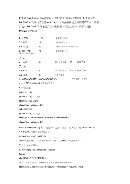
FFT是Fast Fourier Transform(快速傅里叶变换)的简称,FFT算法在MATLAB 中实现的函数是Y=fft(x,n)。
刚接触频谱分析用到FFT时,几乎都会对MATLAB 的fft函数产生一些疑惑,下面以看一个例子(根据MATLA帮助修改)。
Fs = 2000; % 设置采样频率T = 1/Fs; % 得到采用时间L = 1000; % 设置信号点数,长度1 秒t = (0:L-1)*T; % 计算离散时间,% 两个正弦波叠加f1 = 80;A1 = 0.5; % 第一个正弦波100Hz,幅度0.5f2= 150;A2 = 1.0 ; % 第2个正弦波150Hz,幅度 1.0A3 = 0.5; % 白噪声幅度;x = A1*sin(2*pi*f1*t) + A2*sin(2*pi*f2*t); % 产生离散时间信号;y = x + A3*randn(size(t)); % 叠加噪声;% 时域波形图subplot(2,1,1)plot(Fs*t(1:50),x(1:50))title('Sinusoids Signal')xlabel('time (milliseconds)')subplot(2,1,2)plot(Fs*t(1:50),y(1:50))title('Signal Corrupted with Zero-Mean Random Noise')xlabel('time (milliseconds)')NFFT = 2A nextpow2(L); % 设置FFT点数,一般为2 的N次方,如1024,512 等Y = fft(y,NFFT)/L; % 计算频域信号,f = Fs/2*linspace(0,1,NFFT/2+1);%频率离散化,fft后对应的频率是-Fs/2到Fs/2,由NFFT个离散频点表示% 这里只画出正频率;% Plot single-sided amplitude spectrum.figure;plot(f,2*abs(Y(1:NFFT/2+1)));% fft 后含幅度和相位,一般观察幅度谱,并把负频率加上去,title('Single-Sided Amplitude Spectrum of y(t)') xlabel('Frequency (Hz)')ylabel('|Y(f)|') 运行结果时域波形图如图所示: Sinusoids Signal 斗 2 0 -2 0 5 10 15 20 25 30 35 4Q 45 50 time (milliseconds)time (mnliseconds) Signal Corrupted with Zero-Mean Random Noise 幅度谱如下:Frequency (Hz)由图可见,80Hz 的信号幅度为 0.4762,频率为80.08 ,150Hz 的信号频率为150.4,幅度0.9348 , 存在误差。
FPGA FFT_IP核函数的使用说明

FPGA FFT_IP核函数的使用说明一.基本性能特点:(1)采用基-4算法和基-4/2混合基算法;采用频域抽取方式(DIF)的FFT算法;(2)输入数据采用定点方式输入(输入数据为real、imag ,但没有exponent),在运算过程中采用块浮点方式进行运算,使用块浮点结构能够获得最大的SNR 和最少逻辑需求之间的平衡;输出采用指数形式输出(即包含real、imag、exponent),输出结果为:“数据”×(2^(-“指数”));(3)可以完成的FFT变换长度为2^m(6≤m≤14),即64~16384点;数据位宽为8~24bits;(4)如果输入的数据向量不够N点(FFT设置中的转换长度,例如:1024等),则FFT_IP核函数会在输入数据的后面自动进行补0填充,扩展成N点的数据。
(5)输入、输出数据采用有符号复数表示,都采用自然排序方式;(6)支持单倍输出(Signal-output)和四输出(Quad-output)引擎(engine);(7)多路I/O数据流模式:流(Streaming)、缓冲突发(Buffer Burst)、突发(Burst);(8)Version_2.1.0版本的FFT_IP核函数采用的是Atlantic Interface接口协议;Version_7.2版本的FFT_IP核韩式采用的是Avalon Streaming(ST) Interface接口协议。
(9)Version_2.1.0版本不支持RTL级Modelsim仿真,Version_7.2版本支持。
也就是说,2.1.0版本的FFT_IP核函数不能再自己新建的工程中通过QuartusII调用Modelsim进行RTL的仿真。
二.IP_Core的参量设置:(1)Twiddle Precision表示的是旋转因子的位宽精度;Data Precision表示的是输入、输出数据位宽精度。
注意:旋转因子的位宽精度必须小于或等于数据的位宽精度;(2)在Complex Multiplier Implementation选择栏中的Structure列表中选择期望的复数乘法器结构复数乘法器可以使用4个实数乘法器和2个加法/减法器完成,或使用3个乘法器、5个加法器和一些附加的延时单元完成。
DE0使用说明中文

DE0使用说明中文DE0是一款FPGA开发板,由英特尔公司设计并销售。
它具有强大的计算和处理能力,可用于开发各种应用程序,如数字信号处理、图像处理、视频编码和解码、嵌入式系统等。
本文将介绍DE0的硬件架构、开发工具和使用方法。
一、硬件架构DE0采用Altera的Cyclone III FPGA芯片,拥有丰富的资源和先进的器件,包括逻辑元件、内存和时钟电路等。
它还配备了多个接口,如USB、VGA、SD卡和扩展插槽,方便连接外部设备和扩展功能。
二、开发工具三、使用方法2. 创建工程:打开Quartus II软件,选择“Create a new project”,然后按照指导创建一个新的工程。
在创建工程时,需要选择目标设备为Cyclone III,并设置工程选项。
3.设计编写:在工程中创建一个新的设计文件,并使用硬件描述语言编写设计代码。
可以在代码中实现各种功能,如逻辑运算、数据处理、状态机和控制器等。
4. 编译仿真:完成设计代码编写后,可以进行编译和仿真。
Quartus II软件可以对设计进行语法检查和逻辑综合,并生成仿真波形图。
开发者可以使用ModelSim等仿真工具,对设计进行验证和调试。
6.调试测试:在运行设计后,可以使用开发板上的LED显示器、七段数码管、按键开关和接口等进行调试和测试。
开发者可以编写测试程序,通过输入输出数据进行验证和调试,以确保设计的正确性和稳定性。
7.扩展功能:DE0开发板还具有丰富的扩展接口,可以连接各种外部设备和模块。
开发者可以通过扩展插槽连接SDRAM、WiFi模块、音频接口等,实现更复杂的功能和应用。
8.资源分享:DE0开发板有一个活跃的开发者社区,可以在社区上交流和分享设计经验、代码和资源。
在社区上,开发者可以获取更多的学习资料和案例,加速开发进度和提高开发效率。
fft蝶形运算旋转因子变化规律

fft蝶形运算旋转因子变化规律【实用版】目录1.FFT 简介2.蝶形运算在 FFT 中的应用3.旋转因子在蝶形运算中的作用4.旋转因子的变化规律5.FFT 蝶形运算的优化正文1.FFT 简介快速傅里叶变换(FFT)是一种广泛应用于数字信号处理和其他领域的算法,它可以快速地将一个信号从时间域转换到频率域。
由于 FFT 需要进行复杂的数学运算,因此使用 GPU(图形处理器)可以加速其计算过程。
2.蝶形运算在 FFT 中的应用在 FFT 算法中,蝶形运算是一种重要的运算方式。
它通过将输入信号分解成较小的子信号,并对这些子信号进行处理,最终再将处理后的子信号组合成输出信号。
这个过程可以大大减少计算量,提高算法的效率。
3.旋转因子在蝶形运算中的作用在蝶形运算中,旋转因子是一个关键的参数。
它决定了子信号在处理过程中的旋转角度,从而影响最终的输出结果。
因此,正确选择和计算旋转因子是 FFT 算法中一个重要的环节。
4.旋转因子的变化规律根据 FFT 算法的推导过程,可以得到旋转因子的变化规律。
在蝶形运算过程中,旋转因子会按照一定的周期性变化。
具体来说,当子信号的个数为 2 的幂次方时,旋转因子的变化规律为:1, -1, 1, -1,...;当子信号的个数为非 2 的幂次方时,旋转因子的变化规律为:1, -1/2, 1/2, -1/4, 1/4,...。
5.FFT 蝶形运算的优化为了进一步提高 FFT 算法的效率,可以对蝶形运算进行优化。
一种常见的优化方法是采用分治策略,将输入信号分成较小的子信号,并对这些子信号进行并行处理。
另外,还可以使用诸如 Cufft 等开源的 FFT 库,在 GPU 上实现 FFT 算法,以加速计算过程。
总之,FFT 蝶形运算中的旋转因子具有一定的变化规律,正确把握这一规律有助于优化 FFT 算法的性能。
Altera率先测试浮点DSP设计 助力简化算法和成本

Altera 率先测试浮点DSP 设计助力简化算法和成本
电子发烧友网核心提示:Altera 公司昨日宣布,在业界率先在28 nm FPGA 器件上成功测试了复数高性能浮点数字信号处理(DSP)设计。
独立
技术分析公司Berkeley 设计技术有限公司(BDTI)验证了能够在Altera StraTIx V 和Arria V 28 nm FPGA 开发套件上简单方便的高效实现Altera 浮点DSP 设计流程,同时验证了要求较高的浮点DSP 应用的性能。
请访问【对Altera 28nm FPGA 浮点DSP 设计流程和性能的独立分析】,阅读BDTI 完整的FPGA 浮点DSP 分析报告。
Altera 的浮点DSP 设计流程经过规划,能够快速适应可参数赋值接
口的设计更改,其工作环境包括来自MathWorks 的MATLAB 和Simulink,以及Altera 的DSP Builder 高级模块库,支持FPGA 设计人员比传统HDL 设计更迅速的实现并验证复数浮点算法。
这一设计流程非常适合设计人员在应
用中采用高性能DSP,这些应用包括,雷达、无线基站、工业自动化、仪表和医疗图像等。
业界评价
Altera 产品市场总监Alex Grbic 评论说:Altera 的浮点解决方案支持设计人员充分利用FPGA 为DSP 数据通路提供的强大的高性能浮点资源。
通。
Altera FFT MegaCore 函数预应用说明 404说明书
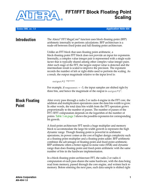
Application Note 404FFT/IFFT Block Floating Point Scaling IntroductionThe Altera ® FFT MegaCore ® function uses block-floating-point (BFP) arithmetic internally to perform calculations. BFP architecture is a trade-off between fixed-point and full floating-point architecture.Unlike an FFT block that uses floating point arithmetic, a block-floating-point FFT block does not provide an input for exponents. Internally, a complex value integer pair is represented with a single scale factor that is typically shared among other complex value integer pairs. After each stage of the FFT, the largest output value is detected and the intermediate result is scaled to improve the precision. The exponent records the number of left or right shifts used to perform the scaling. As a result, the output magnitude relative to the input level is:output*2-exponent For example, if exponent = –3, the input samples are shifted right by three bits, and hence the magnitude of the output is output*23.Block FloatingPointAfter every pass through a radix-2 or radix-4 engine in the FFT core, the addition and multiplication operations cause the data bits width to grow. In other words, the total data bits width from the FFT operation grows proportionally to the number of passes. The number of passes of the FFT/IFFT computation depends on the logarithm of the number of points. Table 1 on page 3 shows the possible exponents for corresponding bit growth.A fixed-point architecture FFT needs a huge multiplier and memory block to accommodate the large bit width growth to represent the high dynamic range. Though floating-point is powerful in arithmetic operations, its power comes at the cost of higher design complexity such as a floating-point multiplier and a floating-point adder. BFP arithmetic combines the advantages of floating-point and fixed-point arithmetic. BFP arithmetic offers a better signal-to-noise ratio (SNR) and dynamic range than does floating-point and fixed-point arithmetic with the same number of bits in the hardware implementation.In a block-floating-point architecture FFT, the radix-2 or radix-4 computation of each pass shares the same hardware, with the data being read from memory, passed through the core engine, and written back to memory. Before entering the next pass, each data sample is shifted right October 2005, ver. 1.0FFT/IFFT Block Floating Point Scaling(an operation called "scaling") if there is a carry-out bit from the additionand multiplication operations. The number of bits shifted is based on thedifference in bit growth between the data sample and the maximum datasample detected in the previous stage. The maximum bit growth isrecorded in the exponent register. Each data sample now shares the sameexponent value and data bit width to go to the next core engine. The samecore engine can be reused without incurring the expense of a largerengine to accommodate the bit growth. The output SNR depends on howmany bits of right shift occur and at what stages of the radix corecomputation they occur. In other words, the signal-to-noise ratio is datadependent and you need to know the input signal to compute the SNR.Calculating Possible Exponent Values Depending on the length of the FFT/IFFT, the number of passes through the radix engine is known and therefore the range of the exponent is known. The possible values of the exponent are determined by the following equations:P = ceil{log4N}, where N is the transform lengthR = 0 if log2N is even, otherwise R=1Single Output range = (–3P+R, P+R–4)Quad Output range = (–3P+R+1, P+R–7)Implementing Scaling These equations translate to the values shown in Table1.f For details of the division by N in the IFFT operation, refer to Equation 2in the Specifications chapter of the FFT MegaCore Function User Guide.Implementing Scaling The scaling algorithm is implemented as follows:1.Determine the length of the resulting full scale dynamic rangestorage register. To get the length, add the width of the data to the number of times the data is shifted (the MAX value shown inTable1). For example, for a 16-bit data, 256-point Quad OutputFFT/IFFT, MAX = –11 and MIN = –3. The MAX value indicates 11 shifts to the left, so the resulting full scaled data width is 16 + 11, or27 bits.2.Map the output data to the appropriate location within theexpanded dynamic range register based upon the exponent value.To continue the above example, the 16-bit output data [15..0] from the FFT/IFFT is mapped to [26..11] for an exponent of –11, to [25..10] for an exponent of –10, to [24..9] for an exponent of –9, and so on. Table1.Exponent Scaling Values for FFT / IFFT Note(1)Single Output Engine Quad Output Engine N P MAX (2)MIN (2)N P MAX (2)MIN (2) 643–9–1643–8–4 1284–1111284–10–2 2564–1202564–11–3 5125–1425125–13–1 10245–15110245–14–2 20486–17320486–160 40966–18240966–17–1 81927–20481927–191 163847–213163847–200 Note to Table1:(1)This table lists the range of exponents, which is the number of scale events thatoccurred internally. For IFFT, the output must be divided by N externally. If more arithmetic operations are performed after this step, the division by N must beperformed at the end to prevent loss of precision.(2)The MAX and MIN values show the number of times the data is shifted. Anegative value indicates shifts to the left, while a positive value indicates shifts to the right.FFT/IFFT Block Floating Point Scaling3.Sign extend the data within the full scale register.A sample of Verilog HDL code that illustrates the scaling of the outputdata (for exponents –11 to –9) with sign extension is shown in thefollowing example:case (exp)6'b110101 : //-11 Set data equal to MSBsbeginfull_range_real_out[26:0] <= {real_in[15:0],11'b0};full_range_imag_out[26:0] <= {imag_in[15:0],11'b0};end6'b110110 : //-10 Equals left shift by 10 with sign extension beginfull_range_real_out[26] <= {real_in[15]};full_range_real_out[25:0] <= {real_in[15:0],10'b0};full_range_imag_out[26] <= {imag_in[15]};full_range_imag_out[25:0] <= {imag_in[15:0],10'b0};end6'b110111 : //-9 Equals left shift by 9 with sign extension beginfull_range_real_out[26:25] <= {real_in[15],real_in[15]};full_range_real_out[24:0] <= {real_in[15:0],9'b0};full_range_imag_out[26:25] <= {imag_in[15],imag_in[15]};full_range_imag_out[24:0] <= {imag_in[15:0],9'b0};end...endcaseIn this example, the output provides a full scale 27-bit word. You need tochoose how many and which bits should be carried forward in theprocessing chain. The choice of bits determines the absolute gain relativeto the input sample level.Figure1 demonstrates the effect of scaling for all possible values for the256-point Quad Output FFT with an input signal level of 5000H. Theoutput of the FFT is 280H when the exponent = –5. The figure illustratesall cases of valid exponent values of scaling to the full scale storageregister [26..0]. Since the exponent is –5, you need to look at the registervalues for that column. This data is shown in the last two columns in thefigure. Note that the last column represents the gain compensated dataafter the scaling (0005000H), which agrees with the input data asexpected. If you want to keep 16 bits for subsequent processing, you canchoose the bottom 16 bits that result in 5000H. However, if you choose adifferent bit range, such as the top 16 bits, then the result is 000AH.Therefore, the choice of bits affects the relative gain through theprocessing chain.Achieving Unity Gain in an IFFT+FFT pairBecause this example has 27 bits of full scale resolution and 16 bits ofoutput resolution, we choose the bottom 16 bits to maintain unity gainrelative to the input signal. Choosing the LSBs is not the only solution orthe correct one for all cases. The choice depends on which signal levels areimportant. One way to empirically select the proper range is bysimulating test cases that implement expected system data. The output ofthe simulations should tell what range of bits to use as the output register.If the full scale data is not used (or just the MSBs), you must saturate thedata to avoid wraparound problems.Figure1.Scaling of Input Data Sample = 5000HAchieving Unity Gain in an IFFT+FFT pair Given sufficiently high precision, such as with floating-point arithmetic, you can theoretically obtain unity gain when an IFFT and FFT are cascaded. However, in BFP arithmetic, special attention must be paid to the exponent values of the IFFT/FFT blocks to achieve the unity gain. This section explains the steps required to derive a unity gain output froman Altera IFFT/FFT MegaCore pair, using BFP arithmetic.FFT/IFFT Block Floating Point ScalingBecause BFP arithmetic does not provide an input for the exponent, youmust keep track of the exponent from the IFFT block if you are feeding theoutput to the FFT block immediately thereafter and divide by N at the endto acquire the original signal magnitude.Figure2 shows the operation of IFFT followed by FFT and derives theequation to achieve unity gain.Figure2.Derivation to Achieve IFFT/FFT Pair Unity GainAny scaling operation on X0 followed by truncation will lose the value ofexp1 and not result in unity gain at x0. Any scaling operation must bedone on X0 only when X0 is the final result. If the intermediate result X0is first padded with exp1 number of zeros and then truncated or if the databits of X0 are truncated, then the scaling information will be lost.One way to keep unity gain is by passing the exp1 value to the output ofthe FFT block. The other way is to preserve the full precision ofdata1*2–exp1 and use this value as input to the FFT block. The disadvantage101 Innovation Drive San Jose, CA 95134(408) 544-7000 Applications Hotline: (800) 800-EPLD Literature Services: *********************Copyright © 2005 Altera Corporation. All rights reserved. Altera, The Programmable Solutions Company, the stylized Altera logo, specific device designations, and all other words and logos that are identified as trademarks and/or service marks are, unless noted otherwise, the trademarks and service marks of Altera Corporation in the U.S. and other countries. All other product or service names are the property of their re-spective holders. Altera products are protected under numerous U.S. and foreign patents and pending applications, maskwork rights, and copyrights. Altera warrants performance of its semiconductor products to current specifications in accordance with Altera's standard warranty, but reserves the right to make chang-es to any products and services at any time without notice. Altera assumes no responsibility or liability arising out of the application or use of any information, product, or service describedherein except as expressly agreed to in writing by Altera Corporation. Altera customersare advised to obtain the latest version of device specifications before relying on any pub-lished information and before placing orders for products or services.Achieving Unity Gain in an IFFT+FFT pairof the second method is a large size requirement for the FFT to accept the input with growing bit width from IFFT operations. The resolution required to accommodate this bit width exceeds, in most cases, the maximum data width supported by the core.f For more information, refer to the FFT/IFFT Unity Gain design exampleat .。
quartus中fft模块使用

注释:(1) 描述数据和旋转因子精度。
(2) 使用Stratix II器件设计,Quartus II软件报告的设计使用的自适应查找表(ALUT)数。
逻辑单元(LE)数ALUT数相关。
(3) 在允许使用M-RAM资源的情况下,前面的数字表明在FFT设计向导中取消使用M-RAM时.M4K-RAM 的模块数。
注释:(1) 同表8.1(1)。
(2) 当使用缓冲突发结构时,在FFT。
向导中可以指定四输出(Quad.output)FFT擎数。
(3) 同表8.1(2)。
(4) 同表8.1(3)。
注释:(1) 同表8.1(1)。
(2) 当使用缓冲突发结构时,在FFI、向导中可以指定四输出(Quad—output)FFT引擎数。
用户可以并行选择1、2或4个四输出引擎。
(3) 在缓冲突发结构中,转换时间(Transform Time)定义为从已经加载N点输入数据块到第一个转换输出样点准备输出之间的时间。
转换时间不包括输出所有转换输出数据块所用的额外N一1个时注释:(1) 同表8.1(1)。
(2) 当使用突发数据流结构时,在FFT向导中可以指定引擎数。
可以并行选择l到2个单输出引擎或1、2或4个四输出引擎。
(3) 同表8.1(2)。
表8.5在stratix Ⅱ器件中使用突发(BurSt)数据流结构的性能注释:(1) 同表8.1(1)。
(2) 在突发I/O数据流结构中,可以在FFT向导中指定引擎数。
可以并行选择1到2个单输出引擎,或1、2或4个四输出引擎。
(3) 转换时间定义为从已经加载输入数据块到第一个转换结果样点(对应于输入数据块)输出之间的时帧(Time )。
转换时间不包括输出所有转换输出数据块的时间。
(4) 同表8.3(4)。
二.FFT兆核函数的应用1 系统要求本节讲述的应用需要下列硬件和软件配置:?装有Windows NT/2000/XP,Red Hat Linux 7.3/8.0或Red Hat企业版,Linux 3.0操作系统的PC机;或装有Solaris 7或8操作系统的Sun工作站。
AOK TFR 2

AOK TFR 2.0 手册1、简介TFR是基于自适应最优核的时频分析软件,该软件包括自适应时频分析的计算内 AOK核及Matlab交互脚本。
计算内核是基于C编译的,并针对Intel P4、AMD作了不同优化;1.0版本中交互脚本只是简单的Matlab命令及参数,可以在Matlab命令行中直接执行tfa命令及相关参数等,可通过直接的tfa命令查询参数调用说明。
在2.0版本中,使用了GUI交互界面,可允许用户进行更多、更加直观的控制操作,可在Matlab命令行直接敲入tfagui进入交互界面,如下所示:2、相关操作单元及其说明⑴:界面中包含3个坐标轴① 左下是信号波形,蓝色是实部,绿色是虚,对实信号进行分析时,虚部是其Hilbert变换,目的为了消除负频干扰。
② 中上是信号的功率谱曲线。
③ 左上是信号的时频表示。
⑵:3个操作区域ⅰ 右上是信号的分析、控制区域,由上而下依次为:① T-F A: 当下面的参数设定好以后,启动自适应时频分析内核。
Ridges: 当信号的时频表示计算完成后,可计算并显示时频面中的脊。
② Fr To: 设定当前信号所要分析的采样点区间,当选择了某一信号时,起止点自动设为1和信号长度。
③ ReS: 对所选择的信号所进行的重采样倍率,>1表示降采样,<1表示升采样。
④ Lag: 设定分析窗宽度(偶数),对于频率调制较慢的信号可以采用较长的宽度(如 128,256)以提高分辨性能,但同时计算时间也相应变长;对于频率调制较快的信号可以采用较短的宽度(如 32,64)以提高分辨性能,但同时计算时间也较短。
⑤ Step:设定分析窗移动的采样步长,缺省为1即每次分析只移动一个采样点。
⑥ Fs:设定所分析信号的采样频率,只用来显示。
⑦ FFT:设定fft长度,越长,频率分辨越精细,缺省512。
⑧ 列表框:Matlab当前工作空间的变量列表,可以通过⑨更新。
可以从列表中用鼠标选中待分析的信号。
切比雪夫Ⅱ型IIR高通滤波器

《数字信号处理课程设计报告》题目:切比雪夫Ⅱ型IIR高通滤波器学院:专业:班级:姓名:指导教师:2012年 6月24日目录引言设计目的 (3)1滤波器设计流程图 (4)2手工完成本实验数字滤波器的初始值设计 (5)2.1确定数字高通滤波器的各项性能指标 (5)2.2由数字高通滤波器的指标转化为模拟高通滤波器的指标 (5)2.3由模拟高通滤波器的指标转化为模拟低通滤波器的指标 (5)2.4手工计算模拟滤波器相关指标 (6)2.5手工计算切比雪夫模拟低通滤波器相关参数 (6)2.6用MATLAB算法设计归一化切比雪夫II型模拟低通滤波器 (7)2.7手工计算把模拟低通滤波器转换成相应的模拟高通滤波器 (8)2.8用MATLAB算法将模拟低通滤波器转换成的模拟高通滤波器 8 2.9把模拟高通滤波器转换成的数字高通滤波器 (9)2.10用MATLAB算法将模拟滤波器转换成相应的数字滤波器 (9)3.在MATLAB基础上分析滤波器结构对其性能指标的影响 (9)3.1直接型 (9)3.2级联型 (11)4在MATLAB基础上分析滤波器参数的字长对其性能指标的影响 (12)4.1直接型 (12)4.2级联型 (14)5.在MATLAB基础上分析滤波器阶数对其性能指标的影响 (16)6 实验心得 (18)7 参考文献 (18)引言随着社会的发展,各种频率的波都在被不断的开发以及利用,这就导致了不同频率的波相互之间的干扰越来越严重,因此滤波器的市场是庞大的。
所以各种不同功能滤波器的设计就越来越重要,在此要求上实现了用各种不同方式来实现滤波器的设计。
本设计通过MATLAB 软件对IIR 型滤波器进行理论上的实现,其中用切比雪夫II 型方式来实现模拟低通滤波器的实现。
设计目的用切比雪夫II 型的设计方法设计一个IIR 数字高通滤波器(模拟频带变换),要求π8.0=phω,π44.0=s ω。
通带最大衰减为dB Ap 3=,阻带最小衰减为dB As 15=1滤波器设计流程图图1 滤波器设计流程方框图2手工完成本实验数字滤波器的初始值设计2.1确定数字高通滤波器的各项性能指标π8.0=ph ω,π44.0=s ω。
FFT MegaCore Function User Guide (PDF)

UG-FFT-10.0
Contents
Chapter 1. About This MegaCore Function
Release Information . . . . . . . . . . . . . . . . . . . . . . . . . . . . . . . . . . . . . . . . . . . . . . . . . . . . . . . . . . . . . . . . . . . . . 1–1 Device Family Support . . . . . . . . . . . . . . . . . . . . . . . . . . . . . . . . . . . . . . . . . . . . . . . . . . . . . . . . . . . . . . . . . . . 1–1 Features . . . . . . . . . . . . . . . . . . . . . . . . . . . . . . . . . . . . . . . . . . . . . . . . . . . . . . . . . . . . . . . . . . . . . . . . . . . . . . . . 1–2 General Description . . . . . . . . . . . . . . . . . . . . . . . . . . . . . . . . . . . . . . . . . . . . . . . . . . . . . . . . . . . . . . . . . . . . . 1–3 Fixed Transform Size Architecture . . . . . . . . . . . . . . . . . . . . . . . . . . . . . . . . . . . . . . . . . . . . . . . . . . . . . . 1–3 Variable Streaming Architecture . . . . . . . . . . . . . . . . . . . . . . . . . . . . . . . . . . . . . . . . . . . . . . . . . . . . . . . . 1–4 MegaCore Verification . . . . . . . . . . . . . . . . . . . . . . . . . . . . . . . . . . . . . . . . . . . . . . . . . . . . . . . . . . . . . . . . . . . 1–4 Performance and Resource Utilization . . . . . . . . . . . . . . . . . . . . . . . . . . . . . . . . . . . . . . . . . . . . . . . . . . . . . . 1–4 Cyclone III Devices . . . . . . . . . . . . . . . . . . . . . . . . . . . . . . . . . . . . . . . . . . . . . . . . . . . . . . . . . . . . . . . . . . . . 1–4 Stratix III Devices . . . . . . . . . . . . . . . . . . . . . . . . . . . . . . . . . . . . . . . . . . . . . . . . . . . . . . . . . . . . . . . . . . . . . 1–8 Stratix IV Devices . . . . . . . . . . . . . . . . . . . . . . . . . . . . . . . . . . . . . . . . . . . . . . . . . . . . . . . . . . . . . . . . . . . . 1–11 Installation and Licensing . . . . . . . . . . . . . . . . . . . . . . . . . . . . . . . . . . . . . . . . . . . . . . . . . . . . . . . . . . . . . . . 1–14 OpenCore Plus Evaluation . . . . . . . . . . . . . . . . . . . . . . . . . . . . . . . . . . . . . . . . . . . . . . . . . . . . . . . . . . . . 1–14 OpenCore Plus Time-Out Behavior . . . . . . . . . . . . . . . . . . . . . . . . . . . . . . . . . . . . . . . . . . . . . . . . . . . . . 1–15
fft信号,波形输出关于原点对称的函数

fft信号,波形输出关于原点对称的函数傅里叶变换(Fast Fourier Transform, FFT)是一种重要的信号处理技术,它可以将时域信号转换为频域信号,从而可以更好地分析和处理信号的频谱特性。
它之所以被广泛应用,主要是因为其具有快速计算速度和高精度的优点。
FFT信号具有一个非常有趣的特点,那就是其波形输出关于原点对称。
这个特性在实际应用中具有重要的指导意义。
首先,我们来解释一下关于原点对称的含义。
当一个函数关于原点对称时,意味着该函数在正半轴上的取值与在负半轴上的取值相同。
也就是说,如果我们将该函数的波形通过原点对折,那么两侧的波形应该完全一样。
那么,为什么FFT信号具有关于原点对称的特性呢?这是因为FFT 算法在进行频域变换时,会将时域信号分解成一系列正弦和余弦波形。
由于正弦和余弦函数具有关于原点对称的特性,所以FFT信号的频谱图也会具备相同的特性。
这种对称性能够大大简化信号分析的复杂性,提高算法的效率。
那么,关于原点对称的FFT信号在实际应用中有哪些重要的作用呢?首先,这种对称性使得信号的频域特性更加清晰明了。
通过观察信号频谱图的对称性,我们可以迅速判断出信号中存在的主要频率成分,从而可以更好地理解信号的特性。
其次,对称性也为信号的滤波和降噪提供了有力的指导。
由于FFT 信号具有关于原点对称的特性,我们可以通过去除频谱图中对称的部分来减少噪声的影响,从而得到更纯净的信号。
这对于提高信号的质量和准确性非常重要。
此外,关于原点对称的FFT信号还在信号合成和频率分析等领域有着广泛的应用。
通过对信号频谱图的观察和分析,我们可以根据不同的对称性特点来合成具有特定频率成分的信号,从而实现信号的调制和解调。
总之,FFT信号的波形输出关于原点对称,这个特性给信号处理领域带来了许多有益的指导和应用。
通过利用其对称性,我们可以更好地理解信号的频谱特性,实现信号的滤波和降噪,以及进行信号合成和频率分析。
快速傅里叶变换(FFT)原理及源程序之欧阳法创编

《测试信号分析及处理》课程作业快速傅里叶变换一、程序设计思路快速傅里叶变换的目的是减少运算量,其用到的方法是分级进行运算。
全部计算分解为M 级,其中N M 2log =;在输入序列()i x 中是按码位倒序排列的,输出序列()k X 是按顺序排列;每级包含2N个蝶形单元,第i 级有i N2个群,每个群有12-i 个蝶形单元; 每个蝶形单元都包含乘r N W 和r N W -系数的运算,每个蝶形单元数据的间隔为12-i ,i 为第i 级; 同一级中各个群的系数W 分布规律完全相同。
将输入序列()i x 按码位倒序排列时,用到的是倒序算法——雷德算法。
自然序排列的二进制数,其下面一个数总比上面的数大1,而倒序二进制数的下面一个数是上面一个数在最高位加1并由高位向低位仅为而得到的。
若已知某数的倒序数是J ,求下一个倒序数,应先判断J 的最高位是否为0,与2Nk =进行比较即可得到结果。
如果J k >,说明最高位为0,应把其变成1,即2NJ +,这样就得到倒序数了。
如果J k ≤,即J 的最高位为1,将最高位化为0,即2NJ -,再判断次高位;与4N k =进行比较,若为0,将其变位1,即4NJ +,即得到倒序数,如果次高位为1,将其化为0,再判断下一位……即从高位到低位依次判断其是否为1,为1将其变位0,若这一位为0,将其变位1,即可得到倒序数。
若倒序数小于顺序数,进行换位,否则不变,防治重复交换,变回原数。
注:因为0的倒序数为0,所以可从1开始进行求解。
二、程序设计框图(1)倒序算法——雷德算法流程图(2)FFT算法流程三、FFT源程序void fft(x,n)int n;double x[];{int i,j,k,l,m,n1,n2;double c,c1,e,s,s1,t,tr;for(j=1,i=1;i<n/2;i++){ m=i;j=2*j;if(j==n)break;} //得到流程图的共几级n1=n-1;for(j=0,i=0;i<n1;i++){if(i<j) //如果i<j,即进行变址{tr=x[j];x[j]=x[i];x[i]=tr;}k=n/2; //求j的下一个倒位序while(k<(j+1)) //如果k<(j+1),表示j的最高位为1{j=j-k; //把最高位变成0k=k/2; //k/2,比较次高位,依次类推,逐个比较,直到某个位为0}j=j+k; //把0改为1 }for(i=0;i<n;i+=2){tr=x[i];x[i]=tr+x[i+1];x[i+1]=tr-x[i+1];}n2=1;for(l=1;l<=m;l++) // 控制蝶形结级数{n4=n2;n2=2*n4;n1=2*n2;e=6.28318530718/n1;for(i=0;i<n;i+=n1) //控制同一蝶形结运算,即计算系数相同蝶形结{tr=x[i];x[i]=tr+x[i+n2];x[i+n2]=tr-x[i+n2];x[i+n2+n4]=-x[i+n2+n4];a=e;for(j=2;j<=(n4-1);j++) //控制计算不同种蝶形结,即计算系数不同的蝶形结{i1=i+j;i2=i-j+n2;i3=i+j+n2;i4=i-j+n1;cc=cos(a);ss=sin(a);a=a+e;t1=cc*x[i3]+ss*x[i4];t2=ss*x[i3]-cc*x[i4];x[i4]=x[i2]-t2;x[i3]=-x[i2]-t2;x[i2]=x[i1]-t1;x[i1]=x[i1]+t1;}}}}四、计算实例及运行结果设输入序列)(i x为其离散傅里叶变换为这里n j eWπ2 -=。
Altera FFT MegaCore 函数版本 2.2.0 初步发布说明说明书

Release NotesFFT MegaCore FunctionThese release notes for the FFT MegaCore® function version 2.2.0 contain the following information:■System Requirements■New Features & Enhancements■Errata Fixed in This Release■Obtain & Install the FFT MegaCore Function■Contacting Altera■Revision HistorySystem Requirements To use the FFT MegaCore function version 2.2.0, the following software and system requirements exist:■ A computer running any of the following operating systems:●Windows 2000/XP●Red Hat Linux 8.0●Red Hat Enterprise Linux 3 WS (with support for 32-bit,AMD64, or Intel EM64T workstations)●Solaris 8 or 9 (32-bit or 64-bit)■Quartus® II software version 5.1 or higher■ModelSim® AE, PE, or SE software version 6.0e or higher■Adobe Acrobat Reader version 5.0 or higher for viewing PDF documentation■Mozilla Firefox 1.0 or higher on computers running the RedHat Linux or Solaris operating systems for following web linksNew Features & Enhancements The list below outlines features and enhancements in this release.■Preliminary support for Stratix® II GX and HardCopy® II devices ■Fixed errata and minor bugsErrata Fixed in This Release The following errata were fixed in this release:Incorrect output for FFT MegaCore function (Burst Mode, Single Output Engine) when stimulated with a delayed inputOctober 2005, MegaCore Version 2.2.0FFT MegaCore FunctionIn burst mode, a delayed master_sink_sop signal may result inincorrect output. When the FFT/IFFT MegaCore is in burst modewith a single output engine and the MegaCore function is stimulatedwith input in which the assertion of the master_sink_sop signal isdelayed, one or more clocks after the master_sink_ena output isactive, (as indicated in the FFT Compiler User Guide), an incorrectoutput may be generated.f For up-to-date errata, refer to the FFT MegaCore function errata sheet onthe Altera web site: /literature/es/es_fft_v220.pdfObtain & Install the FFT MegaCore Function Before you can start using Altera FFT MegaCore function, you must obtain the files and install them on your computer. Altera MegaCore functions can be installed from the MegaCore IP Library CD-ROM during or after Quartus II installation, or downloaded individually from the Altera web site and installed separately.1The following instructions describe the process of downloading and installing the FFT MegaCore function. If you have alreadyinstalled the FFT from the MegaCore IP Library CD-ROM, skipthe instructions below and go to “Directory Structure” onpage4.Download the FFT MegaCore FunctionIf you have Internet access, you can download the FFT MegaCore function from Altera's web site at . Follow the instructions below to obtain the FFT MegaCore function via the Internet. If you do not have Internet access, contact your local Altera representative to obtain the MegaCore IP Library CD-ROM.1.Point your web browser to /ipmegastore.2.Type FFT in the IP MegaSearch box.3.Click Go.4.Choose FFT from the search results page. The product descriptionweb page displays.5.Click Download Free Evaluation on the top right of the productdescription web page. Fill out the registration form and clickSubmit Request.Obtain & Install the FFT MegaCore Function 6.Read the Altera MegaCore license agreement. Turn on the I haveread the license agreement check box and click Proceed toDownload Page.7.Follow the instructions on the FFT MegaCore function downloadand installation page to download the MegaCore function and save it to your hard disk.1Be sure you download the MegaCore function download file specifically for the operating system you will be using. Install the FFT MegaCore Function FilesThe following instructions describe how you install the FFT MegaCore function on computers running the Windows, Solaris, or Linux operating systems.WindowsTo install the FFT MegaCore function on a PC running the Windows operating system, follow these steps:1.Choose Run (Start menu).2.Type <path>\fft-v2.2.0.exe rwhere <path> is the location of the downloaded FFT MegaCorefunction.3.Click OK. The FFT Installation dialog box appears. Follow the on-screen instructions to finish installation.Solaris & LinuxTo install the FFT MegaCore function on a computer running the Solaris operating system, follow these steps:1.Move the compressed files to the desired installation directory andmake that directory your current directory.2.Decompress the package by typing the following command:gzip -d fft-v2.2.0.gz rorgzip -d fft-v2.2.0_solaris.tar.gz rFFT MegaCore Function3.Extract the package by typing the following command:tar xvf fft-v2.2.0_linux.tar rortar xvf fft-v2.2.0_solaris.tar rDirectory StructureFigure1 shows the directory structure after you install the FFTMegaCore, where <path> is the installation directory.Figure1.Directory StructureContacting Altera Although every effort has been made to ensure that this version of the FFT works correctly, if problems occur, use the following contact information to communicate issues to the appropriate Altera representative.For technical support or other information about Altera products, go to the Altera web site at . You can also contact Altera through your local sales representative or any of the sources listed below.Revision HistoryRevision History Table 1 shows the revision history for the FFT MegaCore function. Information TypeUSA & Canada All Other Locations T echnical support /mysupport//mysupport/ 800-800-EPLD (3753)7:00 a.m. to 5:00 p.m. Pacific Time +1 408-544-87677:00 a.m. to 5:00 p.m. (GMT -8:00)Pacific TimeProduct literature Altera literature services ********************* *********************Non-technical customer service 800-767-3753+ 1 408-544-70007:00 a.m. to 5:00 p.m. (GMT -8:00)Pacific TimeFTP site Table 1.FFT MegaCore Function Revision HistoryVersionDate Revision 2.2.0October 2005●Preliminary support for HardCopy II and Stratix II GX devices ●Fixed errata found in FFT MegaCore function v2.2.02.1.3June 2004Fixes errata found in FFT MegaCore function v2.1.2. 13.2October 2002T ool support updates 1.3.1July 2002Added DSP Builder support 1.3.0April 2002●Added support for Stratix devices.●Optimized memory architecture.1.2.0Not Available Improved output data resolution.1.1.1Not Available Re-encrypted design files with the correct product ID 1.1.0Not Available Added support for OpenCore® Plus hardware evaluation.1.0.2March 2001JRE bundled with installer.1.0.1January 2001Various bug fixes 1.0.0January 2001Initial release.101 Innovation DriveSan Jose, CA 95134 (408) 544-7000 Applications Hotline: (800) 800-EPLD Literature Services: *********************Copyright © 2005 Altera Corporation. All rights reserved. Altera, The Programmable Solutions Company, the stylized Altera logo, specific device designations, and all other words and logos that are identified as trademarks and/or service marks are, unless noted otherwise, the trademarks and service marks of Altera Corporation in the U.S. and other countries. All other product or service names are the property of their re-spective holders. Altera products are protected under numerous U.S. and foreign patents and pending applications, maskwork rights, and copyrights. Altera warrants performance of its semiconductor products to current specifications in accordance with Altera's standard warranty, but reserves the right to make chang-es to any products and services at any time without notice. Altera assumes no responsibility or liability arising out of the application or use of any information, product, or service describedherein except as expressly agreed to in writing by Altera Corporation. Altera customersare advised to obtain the latest version of device specifications before relying on any pub-lished information and before placing orders for products or services.FFT MegaCore Function。
一种基于Altera MegaCore实现FFT变换的方法

一种基于Altera MegaCore实现FFT变换的方法许霁【期刊名称】《工业控制计算机》【年(卷),期】2015(000)011【摘要】提出了一种基于Altera公司的FFT IP Core实现FFT变换的方法,对FFT处理引擎的接口功能和工作时序要求进行了说明,介绍了FFT周边功能模块。
在某型水声探测装置上实现了该FFT IP Core的工程运用,并将运算结果与MatLab仿真数据进行比较分析,结果表明该方法可靠、方便、灵活,可以缩短工程开发周期,节约成本。
%This paper presents a FFT transform method based on FFT IP Core of Altera.Firstly interface function and tim-ing requirements of the FFT processing engine are il ustrated.Then the peripheral function modules of the FFT IP Core are introduced.The FFT IP Core is implemented in an underwater acoustic detection device.Final y the results between output of FFT IP Core and simulation data of Matlab are comparative analyzed.This method that can shorten the project development cycle and cost saving is reliable,convenient and flexible.【总页数】3页(P41-42,45)【作者】许霁【作者单位】昆明船舶设备研究试验中心,云南昆明 650051【正文语种】中文【相关文献】1.一种基于FFT变换的超宽带信道盲估计算法 [J], 窦峥;郭黎利;张雅彬2.基于FPGA的FFT变换分析与电路设计实现 [J], 陈军3.基于MegaCore的FFT模块在FPGA上的实现 [J], 姚国珍4.一种基于FFT变换的数据辅助捕获方法 [J], 于高尚;熊蔚明5.一种基于IP Core实现FFT变换的新方法 [J], 陈智;王贵锋;柳莺因版权原因,仅展示原文概要,查看原文内容请购买。
FPGA基础学习(1)--FFTIP核(Quartus)

FPGA基础学习(1)--FFTIP核(Quartus)为了突出重点,仅对I/O数据流为steaming的情况作简要说明,以便快速上⼿,有关FFT ip核模型及每种设置详细介绍请参考官⽅⼿册FFT MegaCore Function User Guide。
1 配置在FFT Megacore Function中选择“parameterize”,弹出对话框。
“Parameters”栏中,选择器件、转换数据的长度、数据精度已经旋转因⼦的精度。
注意旋转因⼦精度必须⼩于等于数据精度。
“Architecture”栏中,有FFT引擎选择,在I/O数据流选择Streanming(流⽔线)的时候,引擎默认为1个四输出引擎。
img“Implementation Options”栏中,Structure中选择乘法器和加法器组合,有4 Mults/2 Adders和3 Mults/5 Adders两种,本例选择前者。
Implement Multiplier in代表实现FFT的逻辑资源分配形式,有DSP Blocks/Logic cells、DSP Blocks ONLY和Logic Cells ONLY三种,Logic cells顾名思义就是消耗FPGA的逻辑资源,⽽DSP Blocks则将⼀部分逻辑资源⽤Embedded Multiplier 9-bit elements表⽰。
本例选择DSP Blocks/Logic cells混合模式。
全局时钟和存储器选择采⽤默认⽅式。
FFT Megacore Function中“step 2”为跟仿真有关的选项,根据需求选择即可。
“step 3”⽣成IP核。
注意,在⽣成IP核的过程中,进度条可能会卡主不动,可能是破解的问题(版本13.1)。
遇到该问题时,多试⼏次,或者改动设计参数,可能会顺利⽣成。
2 信号⽣成的FFT IP核,其端⼝列表如下,相关的详细说明可以在官⽅⼿册中查到:端⼝说明端⼝端⼝类型说明Inverse/改变FFT变换⽅向,置1时为FFI的你变换。
- 1、下载文档前请自行甄别文档内容的完整性,平台不提供额外的编辑、内容补充、找答案等附加服务。
- 2、"仅部分预览"的文档,不可在线预览部分如存在完整性等问题,可反馈申请退款(可完整预览的文档不适用该条件!)。
- 3、如文档侵犯您的权益,请联系客服反馈,我们会尽快为您处理(人工客服工作时间:9:00-18:30)。
Altera FFT兆核函数2.0.0版简介一.FFT兆核函数简介Altera FFT兆核函数2.0.0版是一个高性能、参数化快速傅立叶变换(FFT)处理器,对Altera Stratix I I、Stratix GX、Stratix以及Cyclone器件系列已经进行了设计优化。
FFT兆核函数可以完成高性能复数FFT或逆FFT(IFFT)。
1.FFI2.0.0版本FFT2.0.0版具有以下基本性能:? 完全支持Stratix II、Stratix GX、Stratix以及Cyclone和Cyclone II系列器件。
? 支持Windows、Solal.is以及Linux操作系统。
? 高吞吐量四输出基一4FFT引擎。
? 并行支持多倍单输出和四输出引擎。
? 多路I/O数据流模式:流(Streaming)、缓冲突发(BufferedBurst)以及突发(Burst)。
? Atlantic Compliant输入输出接口。
? 指定参数以产生VHDL和Verilog HDL测试台。
? 每个模块转换方向(FFT/IFFT)可指定。
? 易于使用的IP工具台(Toolbench)接口。
? Altera支持的VHDL和Verflog HDL仿真器上的IP功能仿真模型。
2.特点FFT 2.0.0版具有以下特点:? 基-4算法和基-4/2混合基算法。
? 模块浮点结构,可在处理过程中保持最大数据动态范围。
? 使用嵌入式存储器。
? 最大系统时钟频率大于300 MHz。
? 为使用Stratix II、Stratix GX以及Stratix DSP模块和TriMatrix存储器结构进行了优化。
? 支持OpenCore Plus兆核函数评估。
3.性能FFT兆核函数2.O.O版可以完成变换长度为2m(6≤m≤14)的基一2/4按频率抽选(DIF)的FFT算法。
在FF T兆核函数内部,FKr使用模块浮点结构获得最大SNR和最少逻辑需求之间的平衡。
由于FFT兆核函数的性能在很大程度上取决于FFT引擎结构和I/O数据流,因而很难描述FFI、兆核的所有性能结果。
表8.1、8.2、8.3、8.4和8.5给出FFT兆核函数的大部分器件性能和资源使用结果。
注释:(1) 描述数据和旋转因子精度。
(2) 使用Stratix II器件设计,Quartus II软件报告的设计使用的自适应查找表(ALUT)数。
逻辑单元(LE)数ALUT数相关。
(3) 在允许使用M-RAM资源的情况下,前面的数字表明在FFT设计向导中取消使用M-RAM时.M4K-RAM的模块数。
注释:(1) 同表8.1(1)。
(2) 当使用缓冲突发结构时,在FFT。
向导中可以指定四输出(Quad.output)FFT擎数。
(3) 同表8.1(2)。
(4) 同表8.1(3)。
注释:(1) 同表8.1(1)。
(2) 当使用缓冲突发结构时,在FFI、向导中可以指定四输出(Quad—output)FFT引擎数。
用户可以并行选择1、2或4个四输出引擎。
(3) 在缓冲突发结构中,转换时间(Transform Time)定义为从已经加载N点输入数据块到第一个转换输出样点准备输出之间的时间。
转换时间不包括输出所有转换输出数据块所用的额外N一1个时注释:(1) 同表8.1(1)。
(2) 当使用突发数据流结构时,在FFT向导中可以指定引擎数。
可以并行选择l到2个单输出引擎或1、2或4个四输出引擎。
(3) 同表8.1(2)。
表8.5在stratix Ⅱ器件中使用突发(BurSt)数据流结构的性能注释:(1) 同表8.1(1)。
(2) 在突发I/O数据流结构中,可以在FFT向导中指定引擎数。
可以并行选择1到2个单输出引擎,或1、2或4个四输出引擎。
(3) 转换时间定义为从已经加载输入数据块到第一个转换结果样点(对应于输入数据块)输出之间的时帧(Time )。
转换时间不包括输出所有转换输出数据块的时间。
(4) 同表8.3(4)。
二.FFT兆核函数的应用1 系统要求本节讲述的应用需要下列硬件和软件配置:? 装有Windows NT/2000/XP,Red Hat Linux 7.3/8.0或Red Hat企业版,Linux 3.0操作系统的PC机;或装有Solaris 7或8操作系统的Sun工作站。
? Quartus II 4.1版本或更高版本软件。
? Altera支持的VHDL或Verilog HDL仿真器(可选)。
2 下载并安装FFT下载FFT兆核函数的过程与下载PCI编译器的过程相同,请参考7.2.3节下载PCI译器的过程。
1.安装FFT兆核函数文件可以在Windows、Solaris或Linux操作系统中安装FFT兆核函数。
1) Windows在装有Windows操作系统的PC机上安装FFT的步骤如下:(1) 用鼠标左键双击F载的FF~兆核函数安装文件ffl—v<version>.exe,如fft-v2.0.0exe其中<vers ion>表示FFT兆核函数的版本号。
(2) 在出现FFT安装界面后,根据安装提示完成FFT兆核函数的安装。
2) Solaris在Solaris操作系统上安装FFT的步骤如下(1) 键入下面的命令解压FFT压缩包:gunzip fft—v<version>一solaris.tar.gzr.(回车)(2) 键入下面的命令提取压缩包内容:tar vxf fft—v<version>一solaris.tar(回车)3) Linux在Linux操作系统上安装FFT的步骤如下:(1) 键入下面的命令解压FFT压缩包:gunzip fit—v<version>一linux.tar.gzr(回车)(2) 键入下面的命令提取压缩包内容:tar vxf fft—v<version>一linux.tar(回车)2.目录结构图8.1给出了安装FFT兆核函数文件后生成的目录结构,其中<path>表示FFT兆核函数安装目录。
3.FFT兆核函数设计应用本节介绍如何在Windows操作系统下使用Quartus II软件和IP工具台创建一个FFT兆核函数的用户变量。
当产生一个FFT兆核函数用户变量以后,设计者即可将其加入到总的工程设计中使用。
1.建立一个新的Quartus II工程建立一个新的Quartus II工程文件时,可以使用Quartus II New Project Wizard工程向导为工程文件设置工作目录,分配1二程名称,指定项层设计输入的文件名,同时必须指定FFF兆核函数用户库。
建立新工程的操作步骤如下:(1) 启动Quartus II软件。
(2) 选择File→New Project Wizard命令。
(3) 指定新建工程文件的工作目录,本节使用c:\qdesigns\fft。
(4) 指定工程文件名,本节使用fft—example。
(5) 点击Next按钮。
(6) 点击User Library Pathnames按钮。
(7) 存Library name栏中指定<path>kfft—v<version>klib\,其中<path>表示安装FFT兆核函数的目录,默认安装目录为c:WlegaCore。
点击Add按钮添加用户库,点击OK按钮确定。
(8) 连续点击两次Next按钮,在指定目标器件系列中选择Stratix系列。
(9) 点击Next按钮,选择目标器件。
(10) 点击Finish按钮完成建立新工程。
2.启动IP工具台根据下面的操作步骤,在Quartus II软件中启动IP工具台:(1) 选择Tools→MegaWizard Plug—In Manager命令运行MegaWizard Plug-In管理器,弹出MegaWizard Plug-In Manager对话框。
(2) 选择Create a new custom mega variation选项l并点击Next按钮。
(3) 在Installed Plug—Ins中点击Signal Processing文件夹前面的加号“+”展开,同样展开里面的Transforms文件夹。
(4) 选择FFTv2.0.0。
(5) 指定输出文件类型,如AHDL、Verilog HDL或VHDL,本节选择VHDL。
(6) 指定输出文件目录及文件名,如图8.2所示。
(7) 点击Next按钮,Quartus II软件启动FFT兆核函数IP T具台,如图8.3所示。
3.确定参数使用FFT兆核函数IP工具台创建一个FFT兆核函数用户变量,步骤如下:(1) 点击FFT兆核函数IP 工具台上的Step 1:Parameterize按钮,弹出Parameterize-FFTMegaCore(g ~核函数参数设置)对话框,选择Parameters标签页,如图8.4所示。
(2) 从Target Device Family列表中选择目标器件系列。
(3) 分别从Transform Length、Data Precision和Twiddle Precision列表中选择转换长度、数据精度和旋转因子精度。
注意:旋转因子精度必须小于或等于数据精度。
(4) 设置好FFT兆核函数参数设置对话框的Parameters标签页以后,选择Architecture标签页,如图8. 5所示。
(5) 在I/O Data Flow中选择Buffered Burst,然后在Engine Options栏的FFT EngineArchitec ture列表中选择Quad Output,在Number of Parrallel FFT Engines列表中选择2。
如果在I/O Data Flow中选择Streaming,FFT兆核函数生成一个具有最少Quad OutputFFT引擎数的设计来满足所需的I/O吞吐量。
注意:一个单FFT引擎结构可以达到点数为1024的Steaming I/O数据流FFT的足够性能。
对于Buffered Burst和Burst I/O数据流结构,可以在l、2和4个Quad Output FFT引擎之间选择并行工作;也可以在FFT Engine Architecture列表中选择Single Outpu FFI"引擎结构,则可以选择1或2个引擎并行工作。
如果可以在器件资源和数据吞吐量之间进行折中选择,则选择多个并行引擎可以在牺牲器件资源的情况下减少FFT兆核函数的转换时间。
(6) 设置好FFT兆核函数参数设置对话框的Architecture标签页以后,选择Implementation Options标签页,如图8.6所示。
