AWA5661说明书
噪声测量仪1.1

声级计结构原理图
被测量的声音由传声器接收,传声器将声波转换成电信号,微小的电信 号经前置放大器送到输入衰减器和输入放大器,放大器将信号放大,衰减器 对较大的输入信号加以衰减,使在指示器上获得适当的指示,也使测量量程 扩大。计权滤波器对通过的信号进行频率滤波,使声级计的整机频率响应符 合规定的频率计权特性的要求,以便能测量计权声级。信号再经输出衰减器 和输出放大器后被送到检波器进行检波,交流信号变成直流,并由显示器以 “dB”指示出来。有的声级计还具有“外接滤波器”插孔,用来与其他滤波器 连接进行频谱分析。“放大器输出”插孔输出交流信号,以观察信号波形或 进行测量记录与分析。
普通声级计
普通声级计具备性能稳定、使用简单、价格低廉、携 带方便等优点,在环境、交通噪声、机械和电气噪声 等的测量方面都得到广泛应用,如中国主要的声学测 量仪器生产基地红声器材厂生产的HS5633/B和NDIO 型普通声级计;此外,CEM(香港)公司推出的DT一 8851和DT一8852型普通声级计;这些声级计都满足国 际电工委员会(IEC)651号声级计标准中对作为一般用 途声级计的要求,具有A,C频率计权网络。
HS5633
精密声级计
精密型声级计较普通型不仅具有更高的精度要求,而且融 入了很多先进技术,一般配合带通滤波器使用,进行倍频 程或1/3倍频程频谱分析。杭州爱华公司(杭州爱华电子研 究所)生产的AWA5661型精密声级计是一种袖珍式、高精度 的声学测量仪器,采用了开关电容滤波技术、数字检波技 术等先进技术,通过RS232C数字输出接口可以和计算机联 机进行远程遥控遥测
噪声测量常用仪器
声级计 (A高频 定比带宽法1:频率的固定百分数作为带宽 定比带宽法2:按倍频程去分割整个频率范围,依次在
声级计使用说明

AWA5661型精密脉冲声级计 使用说明书杭州爱华电子仪器有限公司 2003年12月1目录1 概述………………………………………………………2 主要技术性能……………………………………………3 结构及功能…………………………………………………4 使用方法…………………………………………………… 4.1 使用前的准备…………………………………………… 4.2 A 声级、C 声级和声压级测量………………………… 4.3 最大声级的测量………………………………………… 4.4 风罩的使用……………………………………………… 4.5与外接滤波器连接使用…………………………………… 4.6 交流输出和RS-232C 输出的使用……………………… 4.7 校准………………………………………………………4.8 外接电源…………………………………………………4.9 电池检查及更换电池……………………………………4.10 计算机控制软件的使用…………………………………5 注意事项及常见问题………………………………………6 为计量目的规定的信息……………………………………附录A :AWA14421型测试电容传声器在参考方向上的标称自由场响应。
附录B :在近似参考环境条件下声级计在参考方向上的标称自由场响应。
附录C :声级计在不同入射方向时的自由场响应。
附录D :装上φ35×60风罩后,在没有风时声级计在不同方向上的标称自由场响应。
附录E :延伸电缆的使用对测量的影响2 2 5 8 8 8 9 9 9 9 10111111121 概述 AWA5661型精密脉冲声级计是一种测量指数时间计权声级的通用声级计,其性能符合GB/T3785-1983和IEC61672-2002标准对1级声级计的要求,对射频场敏感度属X类。
本仪器由于采用了先进的数字检波技术,使得仪器的稳定性、可靠性大大提高。
而且动态范围大、操作简单、用途广。
AWAIS-1型船舶自动识别系统安装及使用说明书解读
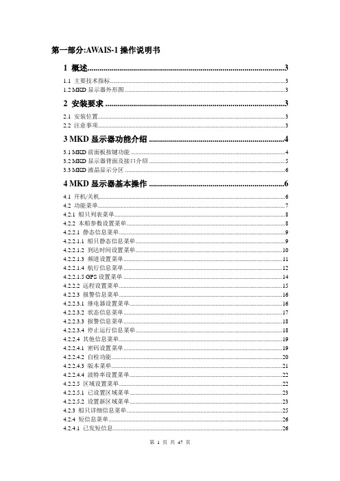
第一部分:AWAIS-1操作说明书1 概述 (3)1.1 主要技术指标 (3)1.2 MKD显示器外形图 (3)2 安装要求 (3)2.1 安装位置 (3)2.2 注意事项 (3)3 MKD显示器功能介绍 (4)3.1 MKD前面板按键功能 (4)3.2 MKD显示器背面及接口介绍 (5)3.3 MKD液晶显示分区 (6)4 MKD显示器基本操作 (6)4.1 开机/关机 (6)4.2 功能菜单 (7)4.2.1 船只列表菜单 (8)4.2.2 本船参数设置菜单 (8)4.2.2.1 静态信息菜单 (9)4.2.2.1.1 船只静态信息菜单 (9)4.2.2.1.2 到达时间设置菜单 (10)4.2.2.1.3 频道设置菜单 (11)4.2.2.1.4 航行信息菜单 (12)4.2.2.1.5 GPS设置菜单 (14)4.2.2.2 远程设置菜单 (15)4.2.2.3 报警信息菜单 (16)4.2.2.3.1 继电器设置菜单 (16)4.2.2.3.2 状态信息菜单 (17)4.2.2.3.3 报警信息菜单 (18)4.2.2.3.4 停止运行信息菜单 (18)4.2.2.4 其他信息菜单 (19)4.2.2.4.1 密码设置菜单 (19)4.2.2.4.2 自检功能 (20)4.2.2.4.3 版本菜单 (21)4.2.2.4.4 波特率设置菜单 (22)4.2.2.5 区域设置菜单 (22)4.2.2.5.1 已设置区域菜单 (23)4.2.2.5.2 设置新区域菜单 (23)4.2.3 船只详细信息菜单 (25)4.2.4 短信息菜单 (26)4.2.4.1 已发短信息 (26)4.2.4.2 已收短信息 (27)4.2.4.3 发短信息 (28)4.2.4.4 远程信息菜单 (32)4.2.5 显示设置 (33)4.2.6 海图显示菜单 (33)4.2.7 本船信息菜单 (34)4.2.8 报警信息对话框 (35)5 维护 (35)第二部分:AWAIS-1安装说明书设备组成 (36)6 安装 (37)6.1 主机安装 (37)6.2 MKD安装 (37)6.3 VHF天线安装 (37)6.4 GPS天线安装 (37)6.5 接线盒安装 (38)7 接线 (40)7.1 电源线连接 (40)7.1.1 主机电源 (40)7.1.2 显示控制器电源 (40)7.2 数据线连接 (40)7.2.1 主机数据线连接方法 (40)7.2.2 显示控制器数据线 (40)7.3 接线盒连线说明 (41)8 指示灯 (43)9 设备安装尺寸 (44)9.1 主机 (44)9.2 显示控制器 (44)9.3 接线盒 (45)10 附录 (46)10.1 参考资料 (46)10.2 输入输出语句列表 (46)10.2.1 传感器输入语句 (46)10.2.2 AIS语句 (46)1 概述本设备(MKD)是上海埃威航空电子有限公司研制的自动识别系统(AIS)的显示控制器, 它采用RS422通信方式与系统主机(AIS)进行数据交换,获取本船及其他安装有AIS设备的船只的航行信息,有效提高航行效率,减少交通事故,保障航行中的财产和生命安全。
AWA5636 型声级计使用说明书

JBL AW566高功率轻量级2路全范围扬声器系统说明书

Key Features:᭤Weather-Resistant, All Fiberglass Enclosure᭤60° x 60° Coverage᭤ 2265H Differential Drive®Low-Frequency Driver᭤ 2432H High Frequency Compression Driver᭤Large PT™ Progressive Transition waveguide for excellent pattern control and low distortion᭤Available in Gray and Black finish᭤400 W, 70/100V Transformer Included ᭤U-type Mounting Bracket Included Applications:᭤Sports Facilities᭤Themed Entertainment Venues᭤Outdoor Entertainment Centers᭤Cruise Ships᭤Water ParksThe AW566 is a high power, lightweight, 2-way, full-range loudspeaker system comprised of the JBL Differential Drive dual voice coil and dual magnetic gap 2265H 380mm (15 in) low-frequency driver and 2432H high-frequency 38 mm (1.5in) exit, 75 mm (3 in) voice-coil compression driver. The large format Progressive Transition wave-guide provides excellent 60° x 60° coverage. The loudspeaker system can used in either the vertical or horizontal orientation. The enclosure is constructed of multilayer glass composite and is heavily braced to maximize low-frequency performance. The 16-gauge stainless steel grille, backed with open cell foam and stainless steel mesh, provides excellent protection in the harshest environments. The system is equipped with a 400 W 70/100V transformer.A corrosion-resistant extra-thick zinc-plated polyester powder coated U-type mounting bracket is included.The AW566 is part of JBL’s AE Series, a versatile family of loudspeakers intended for a wide variety of applications.Specifications:System:Frequency Range (-10 dB):35 Hz – 20 kHzFrequency Response (±3 dB):54 Hz – 18 kHzCoverage Pattern:60° x 60°, rotatable waveguideDirectivity Factor (Q):15.8Directivity Index (DI):12 dBCrossover Frequency: 1.1 kHzLong-Term System Power Rating (IEC):600 W (2400 W peak), 100 hrsMaximum SPL:128 dB-SPL cont avg (134 dB peak)System Sensitivity (1W @ 1m):100 dB SPL70V/100V Transformer Taps:70V: 400 W, 200 W, 100W100V: 400W, 200WTransducers:Low Frequency Driver: 1 x JBL 2265H 380 mm (15 in) Differential Drive driver with 75 mm(3 in) dual voice coilNominal Impedance:8 ohmsSensitivity(1W @ 1m, 98 dB SPLwithin operational band):High Frequency Driver:JBL 2432H, 38 mm (1.5 in) exit compression driver, 75 mm (3 in) voice coil Nominal Impedance:8 ohmsSensitivity(1W @ 1m):113 dB SPLWaveguide:PT-H66HF-1Physical:Enclosure:Hand-Laminated Fiberglass, gray gelcoat (similar to Pantone 420C),available in black (-BK)Suspension Attachment: 2 x M10 for Included U-Bracket, 2 x M6 for aiming stabilization,1x M10 on rear for safety.Grille:Three layer grille assemblies consisting of 16-gauge powder coatedstainless steel, backed with open cell foam and stainless steel mesh.Input Connector:CE-compliant covered barrier strip terminals. Barrier terminals acceptup to 5.2 sq mm (10 AWG) wire or max width 9 mm (.375 in) spadelugs.Environmental Specifications:IP56 per IEC 529Dimensions (H x W x D in 485 x 810 x 478 mmhorizontal cabinet orientation):(19.1 x 31.9 x 18.8 in)Net Weight:28.3 kg (62.5 lb)IEC standard, full bandwidth pink noise with 6 dB crest factor, 100 hours.Calculated based on power rating and sensitivity, exclusive of power compression.Anechoic sensitivity in free field, no additional sensitivity gain from boundary loading.JBL continually engages in research related to product improvement. Changes introduced into existing products without notice are an expression of that philosophy.Professional SeriesAW566High Power 2-Way All Weather Loudspeakerwith 1 x 15" LF & Rotatable Horn᭤AW566 High Power 2-Way All Weather Loudspeaker with 1 x 15" LF & Rotatable HornHorizontal 1/3 Octave Polars᭤AW566 High Power 2-Way All Weather Loudspeaker with 1 x 15" LF & Rotatable HornVertical 1/3 Octave Polars5017361SS AW566CRP09/12 JBL Professional8500 Balboa Boulevard, P.O. Box 2200Northridge, California 91329 U.S.A.© Copyright 2012 JBL Professional。
FLUKE 566 568 说明书
®566/568Infrared Thermometers用户手册August 2007 Rev. 2, 4/08 (Simplified Chinese)© 2007-2008 Fluke Corporation. All rights reserved. Product specifications are subject to change without notice.All product names are trademarks of their respective companies.有限保证和责任限制在正常使用和维护条件下,Fluke 公司保证每一个产品都没有材料缺陷和制造工艺问题。
保证期为从产品发货之日起二(2)年。
部件、产品修理和服务的保证期限为 90 天。
本项保证仅向授权零售商的原始买方或最终用户提供,并且不适用于保险丝和一次性电池或者任何被 Fluke 公司认定由于误用、改变、疏忽、意外非正常操作和使用所造成的产品损坏。
Fluke 公司保证软件能够在完全符合性能指标的条件下至少操作 90 天,而且软件是正确地记录在无缺陷的媒体上。
Fluke 公司并不保证软件没有错误或无操作中断。
Fluke 公司仅授权零售商为最终客户提供新产品或未使用过产品的保证。
但并未授权他们代表 Fluke 公司提供范围更广或内容不同的保证。
只有通过 Fluke 授权的销售商购买的产品,或者买方已经按适当的国际价格付款的产品,才能享受 Fluke 的保证支持。
在一个国家购买的产品被送往另一个国家维修时,Fluke 公司保留向买方收取修理/更换零部件的进口费用的权利。
Fluke 公司的保证责任是有限的,Fluke 公司可以选择是否将依购买价退款、免费维修或更换在保证期内退回到 Fluke 公司委托服务中心的有缺陷产品。
要求保修服务时,请与就近的 Fluke 授权服务中心联系,获得退还授权信息;然后将产品连同问题描述寄至该服务中心,并预付邮资和保险费用(目的地离岸价格)。
Eaton Moeller NZM 电子保护设备说明书

Eaton 259563Eaton Moeller series NZM - Molded Case Circuit Breaker.Undervoltage release, 110-130VAC, +2early N/O, 1, LGeneral specificationsEaton Moeller series NZM release259563NZM1-XUHIVL110-130AC401508259563037 mm66 mm32 mm0.056 kgUL/CSAIECRoHS conform UL489CSA-C22.2 No. 5-09CSA (File No. 22086)UL (Category Control Number DIHS) UL listedUL (File No. E140305)CSA (Class No. 1437-01)CE markingCSA certifiedIEC60947Product Name Catalog Number Model Code EANProduct Length/Depth Product Height Product Width Product Weight Compliances CertificationsIs the panel builder's responsibility. The specifications for the switchgear must be observed.110 VMeets the product standard's requirements.10 msIs the panel builder's responsibility. The specifications for the switchgear must be observed.Does not apply, since the entire switchgear needs to be evaluated.1.5 VAMeets the product standard's requirements.0 VTwo early-make auxiliary contacts0.8 W130 VIs the panel builder's responsibility.15 msUndervoltage release with 2 early-make auxiliary contacts, e.g., for early-make connection of undervoltage release in main switch applications, as well as for interlock and load shedding circuits. For use with emergency-stop devices in connection with an emergency-stop button. When the under-voltage trip is switched eaton-digital-nzm-brochure-br013003en-en-us.pdfeaton-feerum-the-whole-grain-solution-success-story-en-us.pdf eaton-digital-nzm-catalog-ca013003en-en-us.pdfDA-DC-03_NZM1eaton-circuit-breaker-release-nzm-mccb-dimensions.epseaton-circuit-breaker-undervoltage-nzm-mccb-3d-drawing-003.eps M1-XUHIVL110-130ACIL01203002ZThe new digital NZM RangeIntroduction of the new digital circuit breaker NZMeaton-nzm-technical-information-sheet10.11 Short-circuit ratingRated control supply voltage (Us) at AC, 50 Hz - min 10.4 Clearances and creepage distancesMinimum command time - min10.12 Electromagnetic compatibility10.2.5 LiftingPick-up power consumption at AC (undervoltage release) 10.2.3.1 Verification of thermal stability of enclosures Rated control supply voltage (Us) at DC - minFitted with:Pick-up power consumption at DC (undervoltage release) Rated control supply voltage (Us) at AC, 50 Hz - max 10.8 Connections for external conductorsMinimum command time - maxSpecial features BrochuresCatalogs Certification reports DrawingseCAD model Installation instructions Installation videos Technical data sheetsoff, accidental contact with the circuit breaker’s primary contacts is prevented when switched on. Early make of auxiliary contacts on switching on and off (manual operation): approx. 20 ms Undervoltage releases cannot be installed simultaneously with NZM...-XHIV... early-make auxiliary contact or NZM...-XA... shunt release.Rated control supply voltage (Us) at DC - max0 V10.9.3 Impulse withstand voltageIs the panel builder's responsibility.Rated control supply voltage110 - 130 V 50/60 Hz10.6 Incorporation of switching devices and componentsDoes not apply, since the entire switchgear needs to be evaluated.10.5 Protection against electric shockDoes not apply, since the entire switchgear needs to be evaluated.Used withNZM1(-4), N(S)1(-4)Electric connection typeScrew connection10.13 Mechanical functionThe device meets the requirements, provided the information in the instruction leaflet (IL) is observed.10.2.6 Mechanical impactDoes not apply, since the entire switchgear needs to be evaluated.10.9.4 Testing of enclosures made of insulating materialIs the panel builder's responsibility.Number of contacts (normally closed contacts)10.3 Degree of protection of assembliesDoes not apply, since the entire switchgear needs to be evaluated.Voltage typeACDrop-out voltage of undervoltage release AC/DC - min0.35 x UsFrameNZM1Reaction time19 msSuitable forOff-load switchVoltage tolerance - min.85Rated control voltage (relay contacts)130 V AC110 V ACPower consumption0.8 W (sealing DC)1.5 VA (sealing AC)10.2.3.2 Verification of resistance of insulating materials to normal heatMeets the product standard's requirements.Drop-out voltage of undervoltage release AC/DC - max0.7 x Us10.2.3.3 Resist. of insul. mat. to abnormal heat/fire by internal elect. effectsMeets the product standard's requirements.Connection typeWith 3 m connection cable instead of screw termination10.9.2 Power-frequency electric strengthIs the panel builder's responsibility.Voltage tolerance - max1.1Undelayed short-circuit release - min0 ARated control supply voltage (Us) at AC, 60 Hz - min110 V10.7 Internal electrical circuits and connectionsIs the panel builder's responsibility.Terminal capacity (solid/flexible conductor)18 - 14 AWG (2x) at shunt release0.75 mm² - 2.5 mm² (1x) at shunt release with ferrule0.75 mm² - 2.5 mm² (2x) at shunt release with ferrule18 - 14 AWG (1x) for undervoltage releases, off-delayedEaton Corporation plc Eaton House30 Pembroke Road Dublin 4, Ireland © 2023 Eaton. All Rights Eaton is a registered trademark.All other trademarks areproperty of their respective18 - 14 AWG (1x) at shunt release0.75 mm² - 2.5 mm² (1x) for undervoltage releases, off-delayed with ferrule18 - 14 AWG (2x) for undervoltage releases, off-delayed 0.75 mm² - 2.5 mm² (2x) for undervoltage releases, off-delayed with ferruleThe panel builder is responsible for the temperature rise calculation. Eaton will provide heat dissipation data for the devices.Delayed Accessory Undervoltage release Undervoltage release with early-make auxiliary contact Meets the product standard's requirements.Meets the product standard's requirements.Meets the product standard's requirements.130 V20 A10.10 Temperature riseFunctions Type10.2.2 Corrosion resistance10.2.4 Resistance to ultra-violet (UV) radiation 10.2.7 InscriptionsRated control supply voltage (Us) at AC, 60 Hz - max Number of contacts (normally open contacts)Undelayed short-circuit release - max Number of contacts (change-over contacts)Reserved.owners./socialmedia。
AWA5636(5661)通信协议

3.5、AWA5661-1 通讯协议
1.瞬时值传输指令: “AWAA”:主动上传瞬时值开 “AWAa”:主动上传瞬时值关 “AWA0”:读出瞬时值 回答:AWA+数据类型+逗号+数据+逗号+校验和。 数据类型:A 数据:ASCII 码 例:输入 AWAA,回答:AWAA, 25.5dBA,CL 2.1 秒值传输指令 “AWAB”:主动上传 1 秒值开 “AWAb”:主动上传 1 秒值关 “AWA1”:读回 1 秒值 回答:AWA+数据类型+逗号+空格+数据+逗号+电压值+逗号+校验和。 数据类型:B 数据:ASCII 码,主动上传时一秒一次。 例:输入 AWAB,回答:AWAB, 26.6dBA,4.7V,? 3. 设置频率计权 "AWAF0"设为 Z 计权 "AWAF1"设为 C 计权 "AWAF2"设为 A 计权 "AWAF3"设为 B 计权 注:显示器处作相应改变。 杭州爱华仪器有限公司 7
AWA5636/5661 通讯协议 注:显示器处作相应改变。 5. 设置时间计权 "AWAT0"设为 F 档 "AWAT1"设为 S 档 "AWAT2"设为 I 档 注:显示器处作相应改变。 6. 读出仪器当前的传声器灵敏度级 输入: "AWAL" 回答:AWA+数据类型+逗号+数据+逗号+校验和。 数据类型:L : 数据:ASCII 码。 例:输入 AWAL,回答:AWAL,-40.0dB,
3.2、AWA5636-2 通讯协议
1.瞬时值传输指令: “AWAA”:主动上传瞬时值开 “AWAa”:主动上传瞬时值关 “AWA0”:读出瞬时值 回答:AWA+数据类型+逗号+数据+逗号+校验和。 数据类型:A 数据:ASCII 码 例:输入 AWAA,回答:AWAA, 25.5dBA,CL 2.1 秒值传输指令 “AWAB”:主动上传 1 秒值开 “AWAb”:主动上传 1 秒值关 “AWA1”:读回 1 秒值 回答:AWA+数据类型+逗号+空格+数据+逗号+电压值+逗号+校验和。 数据类型:B 数据:ASCII 码,主动上传时一秒一次。 26.6dBA,4.7V,? 例:输入 AWAB,回答:AWAB, 3. 设置频率计权 "AWAF0"设为 Z 计权 "AWAF1"设为 C 计权 杭州爱华仪器有限公司 3
亚瑟海全自动闪光灯说明书

AC -l00V/120V (50/60 Hz) 220V / 240V (50/60 Hz)
73 for ASA100 black-&-white (FEET)
66 for ASA100 colour
(FEET)
22 for ASA100 black-&-white (METRES)
20 for ASA100 co lour
@ The Su per- Lite II also operates on AC, powered by the AC Power Pack accessory.
@ The circuitry of the Super-Lite II is designed for economical power consumption. Pen-light batteries are inexpensive-and you will not waste the battery power.
@ The Super-Lite II has a unique automatic light output stabilizer. The light output of many other electronic flash units considerably decreases as you keep flashing the units. This means you will have to open up your lens aperture. The light output of some unjts goes down to as much as one f/stop extent after 40 flashes . The light output stabilizer of the Super-Lite II constantly maintains its output at its maximum at each flash.
AWA5661说明书

AWA5661型声级计使用说明书® ®杭州爱华仪器有限公司2011年6月注意事项1、第一次使用仪器前,请仔细阅读该说明书。
2、测试传声器的膜片破损不在保修范围之内。
3、其它因使用不当造成的损坏不在保修范围之内。
4、电池应选用高性能碱性电池,该电池不能充电。
不使用时,请将电池取出,以免电池漏液造成仪器损坏。
电池不在保修范围内。
5、仪器需要维修时请带保修单。
11、概述 (1)2、主要技术性能 (1)3、结构及功能 (5)4、使用方法 (8)4.1 使用前的准备 (8)4.2 风罩的使用 (9)4.3 外接电源 (9)4.4电池检查及更换电池 (9)5、校准 (9)5.1声校准 (10)5.2 校准设置 (10)5.3 校准记录列表显示 (11)6、配置1的操作说明 (12)6.1操作界面 (12)6.2 A计权声压级测量 (12)6.3 C计权声压级测量 (13)6.4 时间计权的选择 (13)6.5 最大声级(Lmax)测量及取消 (13)6.6 峰值声压级(Lpeak)测量 (13)6.7 量程调节 (13)6.8 仪器设置 (14)6.8.1 交流输出幅度的调节 (14)6.8.2 交流输出用频率计权的选用 (15)6.8.3 自动关机功能 (15)6.8.4 超限报警功能 (15)6.8.5 串行口波特率 (16)6.8.6 保存仪器设置 (16)6.9 仪器信息 (16)27、配置2的操作说明 (16)7.1操作界面 (16)7.1.1 醒目测量界面 (17)7.1.2 列表测量界面 (17)7.1.3 统计分析界面 (18)7.2 A计权声压级测量 (19)7.3 C计权声压级测量 (19)7.4 时间计权的选择 (19)7.5 最大声级(Lmax)测量及取消 (19)7.6 峰值声压级(Lpeak)测量 (19)7.7 量程调节 (20)7.8 仪器设置 (20)7.8.1 交流输出幅度的调节 (20)7.8.2 交流输出用频率计权的选用 (21)7.8.3 自动关机功能 (21)7.8.4 超限报警功能 (21)7.8.5 串行口波特率 (22)7.8.6 保存仪器设置 (22)7.9 仪器信息 (22)8、配置3的操作 (23)8.1 主菜单 (23)8.2醒目测量界面 (23)8.3 列表测量界面 (24)8.4 设置1 (24)8.4.1 设置1第1页 (24)8.4.2设置1第2页 (26)8.4.3设置1第3页 (27)8.4.4 设置1第4页 (27)8.5 设置2子菜单 (28)38.5.1 启动设置 (28)8.5.2 自动暂停/再启动设置 (31)8.5.3 硬件设置 (31)8.5.4 日历时钟调节 (34)8.5.5记录设置 (34)8.5.6 录音设置 (35)8.6 数据管理子菜单 (36)8.6.1 数据调阅 (36)8.6.2 总清数据 (38)8.6.3 转为U盘模式 (38)8.7 仪器信息 (39)附录1:传输协议(区分大小写) (41)附录A:AWA14425型测试电容传声器在参考方向上的标称自由场响应 (44)附录B:在近似参考环境条件下声级计在参考方向上的标称自由场响应 (45)附录C:声级计在不同入射方向时的自由场响应 (46)附录D:装上SR35×60风罩后,在没有风时声级计在不同方向上的标称自由场响应 (47)附录E:指向设为90时的Z计权响应 (48)附录F:AWA5661带延伸线缆对测试的影响 (49)附录H:名词术语 (51)1.仪器显示常见符号及术语 (51)2. 常用声学测量指标的定义 (52)附件I:装箱清单 (57)1、概述AWA5661型声级计是一种模块化、多功能声级计,其性能符合GB/T3785-2010和IEC61672:2002标准对1级声级计的要求,对射频场敏感度属X类。
AWA5661说明书

AWA5661型声级计使用说明书® ®杭州爱华仪器有限公司2011年6月注意事项1、第一次使用仪器前,请仔细阅读该说明书。
2、测试传声器的膜片破损不在保修范围之内。
3、其它因使用不当造成的损坏不在保修范围之内。
4、电池应选用高性能碱性电池,该电池不能充电。
不使用时,请将电池取出,以免电池漏液造成仪器损坏。
电池不在保修范围内。
5、仪器需要维修时请带保修单。
11、概述 (1)2、主要技术性能 (1)3、结构及功能 (5)4、使用方法 (8)4.1 使用前的准备 (8)4.2 风罩的使用 (9)4.3 外接电源 (9)4.4电池检查及更换电池 (9)5、校准 (9)5.1声校准 (10)5.2 校准设置 (10)5.3 校准记录列表显示 (11)6、配置1的操作说明 (12)6.1操作界面 (12)6.2 A计权声压级测量 (12)6.3 C计权声压级测量 (13)6.4 时间计权的选择 (13)6.5 最大声级(Lmax)测量及取消 (13)6.6 峰值声压级(Lpeak)测量 (13)6.7 量程调节 (13)6.8 仪器设置 (14)6.8.1 交流输出幅度的调节 (14)6.8.2 交流输出用频率计权的选用 (15)6.8.3 自动关机功能 (15)6.8.4 超限报警功能 (15)6.8.5 串行口波特率 (16)6.8.6 保存仪器设置 (16)6.9 仪器信息 (16)27、配置2的操作说明 (16)7.1操作界面 (16)7.1.1 醒目测量界面 (17)7.1.2 列表测量界面 (17)7.1.3 统计分析界面 (18)7.2 A计权声压级测量 (19)7.3 C计权声压级测量 (19)7.4 时间计权的选择 (19)7.5 最大声级(Lmax)测量及取消 (19)7.6 峰值声压级(Lpeak)测量 (19)7.7 量程调节 (20)7.8 仪器设置 (20)7.8.1 交流输出幅度的调节 (20)7.8.2 交流输出用频率计权的选用 (21)7.8.3 自动关机功能 (21)7.8.4 超限报警功能 (21)7.8.5 串行口波特率 (22)7.8.6 保存仪器设置 (22)7.9 仪器信息 (22)8、配置3的操作 (23)8.1 主菜单 (23)8.2醒目测量界面 (23)8.3 列表测量界面 (24)8.4 设置1 (24)8.4.1 设置1第1页 (24)8.4.2设置1第2页 (26)8.4.3设置1第3页 (27)8.4.4 设置1第4页 (27)8.5 设置2子菜单 (28)38.5.1 启动设置 (28)8.5.2 自动暂停/再启动设置 (31)8.5.3 硬件设置 (31)8.5.4 日历时钟调节 (34)8.5.5记录设置 (34)8.5.6 录音设置 (35)8.6 数据管理子菜单 (36)8.6.1 数据调阅 (36)8.6.2 总清数据 (38)8.6.3 转为U盘模式 (38)8.7 仪器信息 (39)附录1:传输协议(区分大小写) (41)附录A:AWA14425型测试电容传声器在参考方向上的标称自由场响应 (45)附录B:在近似参考环境条件下声级计在参考方向上的标称自由场响应 (46)附录C:声级计在不同入射方向时的自由场响应 (47)附录D:装上SR35×60风罩后,在没有风时声级计在不同方向上的标称自由场响应 (48)附录E:指向设为90时的Z计权响应 (49)附录F:AWA5661带延伸线缆对测试的影响 (49)附录H:名词术语 (52)1.仪器显示常见符号及术语 (52)2. 常用声学测量指标的定义 (53)附件I:装箱清单 (58)1、概述AWA5661型声级计是一种模块化、多功能声级计,其性能符合GB/T3785-2010和IEC61672:2002标准对1级声级计的要求,对射频场敏感度属X类。
AWA6228+1 1OCT 使用说明书

杭州爱华仪器有限公司
目录
1 概述.............................................................................................................1 2 主要性能指标.............................................................................................1 3 软件使用.....................................................................................................1
5.1.1 1/1OCT 测量结果的调阅......................................................7 5.1.2 数字记录结果的调阅........................................................... 9 5.2 数据删除..........................................................................................9 5.2.1 数据全删...............................................................................9 5.2.2 单组数据删除.....................................................................10 5.2.3 多组数据删除.....................................................................10 5.3 数据打印........................................................................................ 11 5.3.1 单组打印.............................................................................14 5.3.2 多组打印.............................................................................16
NCP5662 NCV5662 线性调节器 - 低输出电压、超快速、低落差、启用 2.0 A说明书

NCP5662, NCV5662Linear Regulator - Low Output Voltage, Ultra-Fast, Low Dropout, Enable2.0 AThe NCP5662/NCV5662 is a high performance, low dropout linear regulator designed for high power applications that require up to 2.0 A current. It is offered in both fixed and adjustable output versions. With output voltages as low as 0.9 V and ultra−fast response times for load transients, the NCP5662/NCV5662 also provides additional features such as Enable and Error Flag (for the fixed output version), increasing the utility of these devices. A thermally robust, 5 pin D2PAK or DFN8 package, combined with an architecture that offerslow ground current (independent of load), provides for a superior high−current LDO solution.Features•Ultra−Fast Transient Response (Settling Time: 1−3 m s)•Low Noise Without Bypass Capacitor (26 m V rms)•Low Ground Current Independent of Load (3.0 mA Maximum)•Fixed/Adjustable Output V oltage Versions•Enable Function•Error Flag (Fixed Output Version)•Current Limit Protection•Thermal Shutdown Protection (160°C)•0.9 V Reference V oltage for Ultra−Low Output Operation •Power Supply Rejection Ratio > 65 dB•NCV Prefix for Automotive and Other Applications Requiring Unique Site and Control Change Requirements; AEC−Q100 Qualified and PPAP Capable•These are Pb−Free DevicesApplications•Servers•ASIC Power Supplies•Post Regulation for Power Supplies•Constant Current Source•Networking Equipment•Gaming and STB ModulesD2PAKDS SUFFIXCASE 936A−02x= P or Vy=A for Adjustable VersionB for Fixed 1.5 V VersionC for Fixed 3.3 V VersionD for Fixed 1.2 V VersionE for Fixed 1.8 V VersionF for Fixed 2.5 V VersionG for Fixed 2.8 V VersionH for Fixed 3.0 V VersionA= Assembly LocationL= Wafer LotY=YearWW= Work WeekG or G= Pb−Free PackageMARKING DIAGRAMS ANDPIN ASSIGNMENTSx5662DSyAWLYWWGSee detailed ordering and shipping information in the package dimensions section on page 13 of this data sheet.ORDERING INFORMATION1NCDFN8MN SUFFIXCASE 488AFNCP5662yALYW GG(Note: Microdot may be in either location)Tab = GNDPin 1 = EN2 = V in3 = GND4 = V out5 = ADJ/EFPin1 = EF2 = GND3 = N/C4 = EN5, 6 = V in7, 8 = V outPin 1 = ADJ2 = GND3 = N/C4 = EN5, 6 = V in7 = V out8 = N/CFixed Version Adjustable VersionFigure 1. Typical Application Schematic, FixedOutputONOFFONOFF outFigure 2. Typical Application Schematic,Adjustable OutputPIN FUNCTION DESCRIPTIONPin Adj/Fixed D 2PAKPin Adj/Fixed DFN8Pin NameDescription14ENEnable. This pin allows for on/off control of the regulator. To disable the device, connect to Ground. If this function is not in use, connect to V in .25, 6*V in Positive Power Supply Input Voltage 3, TAB 2GND Power Supply Ground 47, 8V outRegulated Output Voltage51ADJ(Adjustable Version)This pin is connected to the resistor divider network and programs the output voltage.51EF(Fixed Version)An Error Flag is triggered when the output voltage is out of regulation excluding transient signals that may occur. Requires a pullup resistor f 100 k W .−3, 8Pin 3 N/C on Fixed & ADJ Version while Pin 8 N/C on ADJ Version onlyNo connection. True no connect. PCB runs allowable.−EPADEPADExposed thermal pad should be connected to ground.*Pins 5 and 6 must be connected together externally for output current full range operation.outENFigure 3. Block Diagram, Fixed OutputoutENFigure 4. Block Diagram, Adjustable OutputABSOLUTE MAXIMUM RATINGSRating Symbol Value Unit Input Voltage (Note 1)V in18V Output Pin Voltage V out−0.3 to (Vin +0.3)V Adjust Pin Voltage V ADJ−0.3 to (Vin +0.3)V Enable Pin Voltage V EN−0.3 to (Vin +0.3)V Error Flag Voltage V EF−0.3 to (Vin +0.3)V Error Flag Current I EF 3.0mA Maximum Junction Temperature T J(max)150°C Stresses exceeding those listed in the Maximum Ratings table may damage the device. If any of these limits are exceeded, device functionality should not be assumed, damage may occur and reliability may be affected.NOTE:This device series contains ESD protection and exceeds the following tests:Human Body Model (HBM), Class 3A, 2000 VMachine Model (MM), Class C, 200 VCharge Device Model (CDM), Class IV, 2000 V.1.Refer to Electrical Characteristics and Application Information for Safe Operating Area.THERMAL CHARACTERISTICSRating Symbol Value Unit Thermal Characteristics, D2PAK (Notes 1 and 2)Thermal Resistance, Junction−to−Ambient Thermal Resistance, Junction−to−Case Thermal Reference, Junction−to−Lead R q JAR q JCR Y JL455.07.0°C/WThermal Characteristics, DFN8 (Notes 1 and 2)Thermal Resistance, Junction−to−Ambient Thermal Reference, Junction−to−Lead (Note 3)R q JAR Y JL7814°C/W2.As measured using a copper heat spreading area of 1 sq in copper, 1 oz copper thickness.3.Lead 6.OPERATING RANGESRating Symbol Value Unit Operating Input Voltage (Note 1)V in(V out+V DO), 2 to 9 (Note 4)VOperating Ambient Temperature Range NCP5662NCV5662T A−40 to +85−40 to +125°CStorage Temperature Range T stg−55 to +150°C 4.Minimum V in = (V out + V DO) or 2 V, whichever is higher.Characteristic Symbol Min Typ Max Unit ADJUSTABLE OUTPUT VERSIONOutput Noise Voltage V n−26−m V rmsOutput VoltageT A= 25°C (V in= V out +1.5 V to 7.0 V, I out = 10 mA to 2.0 A)T A = −20 to +125°C (V in= V out +1.5 V to 7.0 V, I out = 10 mA to 2.0 A) T A = −40 to +150°C (V in= V out +1.5 V to 7.0 V, I out = 10 mA to 2.0 A)V out(−1%)(−1.5%)(−2%)−0.9−(+1%)(+1.5%)(+2%)VAdjustable Pin Input Current I ADJ−40−nA Line Regulation (I out = 10 mA, V out+1.5 V < V in < 7.0 V)REG line−0.03−% Load Regulation (10 mA < I out < 2.0 A)REG load−0.03−% Dropout Voltage (I out = 2.0 A)V DO− 1.0 1.3V Peak Output Current Limit I out(peak) 2.0−−A Internal Current Limitation I LIM− 3.0−ARipple Rejection (120 Hz) Ripple Rejection (1 kHz)RR−−7065−−dBGround CurrentI out = 2.0 ADisabled StateI GNDI GND(DIS)−−1.3103.0300mAm AEnable Input Threshold VoltageVoltage Increasing, On state, Logic HighVoltage Decreasing, Off state, Logic Low V EN1.3−−−−0.3VEnable Input CurrentEnable Pin Voltage = 0.3 V maxEnable Pin Voltage = 1.3 V min I EN−−0.50.5−−m A5.Performance guaranteed over specified operating conditions by design, guard banded test limits, and/or characterization, production tested atT J = T A = 25°C. Low duty cycle pulse techniques are used during testing to maintain the junction temperature as close to ambient as possible.Characteristic Symbol Min Typ Max Unit FIXED OUTPUT VOLTAGEOutput Noise Voltage (V out = 0.9 V)V n−26−m V rmsOutput Voltage (Note 7)T A= 25°C (V in= V out +1.5 V to 7.0 V, I out = 10 mA to 2.0 A)T A = −20 to +125°C (V in= V out +1.5 V to 7.0 V, I out = 10 mA to 2.0 A) T A = −40 to +150°C (V in= V out +1.5 V to 7.0 V, I out = 10 mA to 2.0 A)V out(−1%)(−1.5%)(−2%)−V out(nom)−(+1%)(+1.5%)(+2%)VLine Regulation (I out = 10 mA, V out+1.5 V < V in < 7.0 V)REG line−0.03−% Load Regulation (10 mA < I out < 2.0 A)REG load−0.2−% Dropout Voltage (I out = 2.0 A)V DO− 1.0 1.3V Peak Output Current Limit I out(peak) 2.0−−A Internal Current Limitation I LIM− 3.0−ARipple Rejection (120 Hz) Ripple Rejection (1 kHz)RR−−7065−−dBGround CurrentI out = 2.0 ADisabled StateI GNDI GND(DIS)−−1.3303.0300mAm AEnable Input Threshold VoltageVoltage Increasing, On state, Logic HighVoltage Decreasing, Off state, Logic Low V EN1.3−−−−0.3VEnable Input CurrentEnable Pin Voltage = 0.3 V maxEnable Pin Voltage = 1.3 V min I EN−−0.50.5−−m AError Flag Voltage Threshold (Fixed Output)V EF(VT)919497% of V out Error Flag Output Low Voltage Saturation (I EF = 1.0 mA)V EF(SAT)−200−mV Error Flag Leakage I EF(leakage)− 1.0−m A Error Flag Blanking Time (Note 8)t EF−50−m s6.Performance guaranteed over specified operating conditions by design, guard banded test limits, and/or characterization, production tested atT J = T A = 25°C. Low duty cycle pulse techniques are used during testing to maintain the junction temperature as close to ambient as possible.7.Fixed output voltage available at 0.9 V per request.8.Can be disabled per customer request.(Typical characteristics were measured with the same conditions as electrical characteristics, unless otherwise noted)I out , OUTPUT CURRENT (A)V D O , D R O P O U T V O L T A G E (V )T A , AMBIENT TEMPERATURE (°C)I S C , S H O R T C I R C U I T L I M I T (A)00.51.01.52.02.5−50−25255075100125150T A , AMBIENT TEMPERATURE (°C)I G N D , G R O U N D C U R R E N T (m A )Figure 5. Dropout Voltage vs. TemperatureFigure 6. 1.5 V Dropout Voltage vs. Output CurrentT A , AMBIENT TEMPERATURE (°C)V D O , D R O P O U T V O L T A G E (V )00.20.40.60.81.2−50−2502550751001251501.022.252.52.7533.5−50−2502550751001251503.253.03.50.70.80.91.01.11.21.3I out , OUTPUT CURRENT (A)V D O , D R O P O U T V O L T A G E (V )Figure 7. 3.3 V Dropout Voltage vs. Output CurrentFigure 8. Ground Current vs. TemperatureFigure 9. Short Circuit Current Limit vs.TemperatureI out , OUTPUT CURRENT (A)V o u t , O U T P U T V O L T A G E (V )V in , INPUT VOLTAGE (V)V o u t , O U T P U T V O L T A G E (V )Figure 10. 1.5 V Output Voltage vs. Input Voltage1.61.41.21.00.80.60.40.20I out , OUTPUT CURRENT (A)V o u t , O U T P U T V O L T A G E (V )V in , INPUT VOLTAGE (V)V o u t , O U T P U T V O L T A G E (V )Figure 11. 3.3 V Output Voltage vs. Input Voltage3.02.62.21.81.41.00.60.20Figure 12. 1.5 V Output Voltage vs. Output LoadCurrent Figure 13. 3.3 V Output Voltage vs. Output LoadCurrent3.4Figure 14. Output Current vs. Input −OutputVoltage DifferentialF, FREQUENCY (kHz)R R , R I P P L E R E J E C T I O N (d B )Figure 15. Ripple Rejection vs. FrequencyO U T P U T C U R R E N T (A )INPUT −OUTPUT VOLTAGE DIFFERENTIAL (V)1.21.00.80.60.40.20.0201610201412468F, FREQUENCY (kHz)N O I S E D E N S I T Y (n V r m s /ǨH z )1020304050607080100F, FREQUENCY (kHz)N O I S E D E N S I T Y (n V r m s /ǨH z )90Start 1.0 kHzStop 100 kHz Start 1.0 kHzStop 100 kHzFigure 16. Noise Density vs. Frequency Figure 17. Noise Density vs. Frequency1.0 A /D i vI o u t50 m V /D i vV o u tI out = 2.0 A to 10 mAV in = 3.3 VV out = 1.5 V Fixed C in = 150 m F C out = 150 m F T A = 25°CTIME (1.0 m s/Div)V in = 3.3 VV out = 1.5 V Fixed C in = 150 m F C out = 150 m F T A = 25°CTIME (100 ns/Div)V in = 3.3 VV out = 1.5 V Fixed C in = 150 m F C out = 150 m F T A = 25°C I out = 10 mA to 2.0 ATIME (1.0 m s/Div)Figure 18. Load Transient ResponseFigure 19. Load Transient ResponseFigure 20. Load Transient ResponseFigure 21. Load Transient ResponseV in = 3.3 VV out = 1.5 V Fixed C in = 150 m F C out = 150 m F T A = 25°CI out = 10 mA to 2.0 ATIME (100 ns/Div)1.0 A /D i v20 m V /D i vI o u tV o u t1.0 A /D i v20 m V /D i v I o u tV o u t1.0 A /D i v50 m V /D i vI o u tV o u tI out = 2.0 A to 10 mA1.0 A /D i vI o u t50 m V /D i vV o u tV in = 4.0 V V out = 0.9 V C in = 150 m F C out = 10 m F T A = 25°CTIME (200 ns/Div)Figure 22. Load Transient ResponseFigure 23. Load Transient ResponseV in = 4.0 V V out = 0.9 V C in = 150 m F C out = 10 m F T A = 25°CI out = 10 mA to 2.0 ATIME (200 ns/Div)1.0 A /D i v20 m V /D i vI o u tV o u tI out = 2.0 A to 10 mAAPPLICATION INFORMATIONThe NCP5662 is a high performance low dropout 2.0 A linear regulator suitable for high power applications, featuring an ultra−fast response time and low noise without a bypass capacitor. It is offered in both fixed and adjustable output versions with voltages as low as 0.9 V. Additional features, such as Enable and Error Flag (fixed output version) increase the utility of the NCP5662. It is thermally robust and includes the safety features necessary during a fault condition, which provide for an attractive high current LDO solution for server, ASIC power supplies, networking equipment applications, and many others.Input CapacitorThe recommended input capacitor value is a 150 m F OSCON with an Equivalent Series Resistance (ESR) of 50 m W. It is especially required if the power source is located more than a few inches from the NCP5662. This capacitor will reduce device sensitivity and enhance the output transient response time. The PCB layout is very important and in order to obtain the optimal solution, the Vin and GND traces should be sufficiently wide to minimize noise and unstable operation.Output CapacitorProper output capacitor selection is required to maintain stability. The NCP5662 is guaranteed to be stable at an output capacitance of, C out > 10 m F with an ESR between 50 m W and 300 m W over the output current range of 10 mA to 2.0 A. For PCB layout considerations, place the recommended ceramic capacitor close to the output pin and keep the leads short. This should help ensure ultra−fast transient response times.Adjustable Output OperationThe application circuit for the adjustable output version is shown in Figure 2. The reference voltage is 0.9 V and the adjustable pin current is typically 40 nA. A resistor divider network, R1 and R2, is calculated using the following formula:R1+R2ǒV out V ref*1ǓGNDFigure 24. To achieve the minimum output voltage, ADJ to V out has to be connected together Current Limit OperationAs the peak output current increases beyond its limitation, the device is internally clampled to 3.0 A, thus causing the output voltage to decrease and go out of regulation. This allows the device never to exceed the maximum power dissipation.Error Flag OperationThe Error Flag pin on the NCP5662 will produce a logic Low when it drops below the nominal output voltage. Refer to the electrical characteristics for the threshold values at which point the Error Flag goes Low. When the NCP5662 is above the nominal output voltage, the Error Flag will remain at logic High.The external pullup resistor needs to be connected between V in and the Error Flag pin. A resistor of approximately 100 k W is recommended to minimize the current consumption. No pullup resistor is required if the Error Flag output is not being used.Thermal ConsiderationThe maximum package power dissipation is:P D+T J(max)*T AR q JAThe bipolar process employed for this IC is fully characterized and rated for reliable 18 V operation. To avoid damaging the part or degrading it’s reliability, power dissipation transients should be limited to under 30 W for D2PAK. For open−circuit to short−circuit transient,P DTransient = V in(operating max) * I SC.Figure 25. DFN8 Thermal Resistance vs. Copper AreaCOPPER AREA (mm 2)3903402902401901409040q J A (°C /W )Figure 26. Test Board used for EvaluationORDERING INFORMATIONDeviceNominal Output VoltagePackageShipping †NCP5662DSADJR4G Adj (Pb −Free)D 2PAK800 / Tape & ReelNCP5662DS12R4G Fixed, 1.2 V (Pb −Free)NCP5662DS15R4G Fixed, 1.5 V (Pb −Free)NCP5662DS18R4G Fixed, 1.8 V (Pb −Free)NCP5662DS25R4G Fixed, 2.5 V (Pb −Free)NCP5662DS28R4G Fixed, 2.8 V (Pb −Free)NCP5662DS30R4G Fixed, 3.0 V (Pb −Free)NCP5662DS33R4G Fixed, 3.3 V (Pb −Free)NCV5662DSADJR4G*Adj (Pb −Free)NCV5662DS15R4G*Fixed, 1.5 V (Pb −Free)NCV5662DS33R4G*Fixed, 3.3 V (Pb −Free)NCP5662MNADJR2G Adj (Pb −Free)DFN83000 / Tape & ReelNCP5662MN15R2G Fixed, 1.5 V (Pb −Free)NCP5662MN33R2GFixed, 3.3 V (Pb −Free)†For information on tape and reel specifications, including part orientation and tape sizes, please refer to our Tape and Reel Packaging Specifications Brochure, BRD8011/D.*NCV Prefix for Automotive and Other Applications Requiring Unique Site and Control Change Requirements; AEC −Q100 Qualified and PPAP CapableD2PAK 5−LEAD CASE 936A−02 ISSUE DNOTES:1.DIMENSIONING AND TOLERANCING PER ANSIY14.5M, 1982.2.CONTROLLING DIMENSION: INCH.3.TAB CONTOUR OPTIONAL WITHIN DIMENSIONS AAND K.4.DIMENSIONS U AND V ESTABLISH A MINIMUMMOUNTING SURFACE FOR TERMINAL 6.5.DIMENSIONS A AND B DO NOT INCLUDE MOLDFLASH OR GATE PROTRUSIONS. MOLD FLASHAND GATE PROTRUSIONS NOT TO EXCEED 0.025(0.635) MAXIMUM.DIMAMIN MAX MIN MAXMILLIMETERS0.3860.4039.80410.236INCHESB0.3560.3689.0429.347C0.1700.180 4.318 4.572D0.0260.0360.6600.914E0.0450.055 1.143 1.397G0.067 BSC 1.702 BSCH0.5390.57913.69114.707K0.050 REF 1.270 REFL0.0000.0100.0000.254M0.0880.102 2.235 2.591N0.0180.0260.4570.660P0.0580.078 1.473 1.981RS0.116 REF 2.946 REFU0.200 MIN 5.080 MINV0.250 MIN 6.350 MIN 5−LEAD D2PAKSCALE 3:1ǒmm inchesǓSOLDERING FOOTPRINT0_8_0_8_8 PIN DFN, 4x4CASE 488AF ISSUE CNOTES:1.DIMENSIONS AND TOLERANCING PER ASME Y14.5M, 1994.2.CONTROLLING DIMENSION: MILLIMETERS.3.DIMENSION b APPLIES TO PLATEDTERMINAL AND IS MEASURED BETWEEN 0.15 AND 0.30MM FROM TERMINAL TIP .4.COPLANARITY APPLIES TO THE EXPOSED PAD AS WELL AS THE TERMINALS.5.DETAILS A AND B SHOW OPTIONAL CON-STRUCTIONS FOR TERMINALS.DIM MIN MAX MILLIMETERS A 0.80 1.00A10.000.05A30.20 REF b 0.250.35D 4.00 BSC D2 1.91 2.21E 4.00 BSC E2 2.09 2.39e 0.80 BSC K 0.20−−−L 0.300.502X8XSEATINGPLANE*For additional information on our Pb −Free strategy and soldering details, please download the ON Semiconductor Soldering and Mounting Techniques Reference Manual, SOLDERRM/D.SOLDERING FOOTPRINT*L1DETAIL AL OPTIONAL CONSTRUCTIONSDETAIL BALTERNATE CONSTRUCTIONSL1−−−0.15DIMENSIONS: MILLIMETERSON Semiconductor and are trademarks of Semiconductor Components Industries, LLC dba ON Semiconductor or its subsidiaries in the United States and/or other countries.ON Semiconductor owns the rights to a number of patents, trademarks, copyrights, trade secrets, and other intellectual property. A listing of ON Semiconductor’s product/patent coverage may be accessed at ON Semiconductor makes no warranty, representation or guarantee regarding the suitability of its products for any particular purpose, nor does ON Semiconductor assume any liability arising out of the application or use of any product or circuit, and specifically disclaims any and all liability, including without limitation special, consequential or incidental damages.PUBLICATION ORDERING INFORMATION。
施耐德电气 ALTIVAR61 变频器 产品目录说明书

噪音仪操作规程

噪音仪操作规程次21、0 目的为规范化本公司噪音仪的使用、保养,确保公司产品质量符合规定要求,满足客户的要求。
2、0 范围适用于本公司AWA5661噪音仪。
3、0参考标准执行GB/T3785-xx 和IEC61672:2002 标准对1 级声级计的要求;4、0 测试步骤:4、1测试仪器与工具:图二,声级计图一,传感器与支架图三,静音室图四,电脑主机4、2 按照图五把传感器、数据线与声级计连接线;图六,声级计外形图图五,传感器、数据线与声级计连接4、3 按声级计上的开机键打开仪器电源,仪器显示如右图八,传感器与工件接触图七,操作页面4、4 选择子菜单中测量选项,仪器显示如下:4、5 打开电脑,在电脑桌面上打开仪器操作软件。
进入仪器操作页面(如图七);图八,电机与传感头安装图七,操作页面4、6 打开静音室门,把传感器头放好,连接好被测电机按规定要求摆放传感头与被测电机的距离(如上图八)4、7 单击操作页面上的连接键点击启动,开始接收数据,并画图和保存你所设置的记入时间,在这段记录时间内的瞬时声压值。
并计算出这段时间内的最大值和最小值,以及平均值。
4、8 记录好数据,长按外形图上的返回键对声级计关机,电脑关机,取出被测电机;5、0维护与保养:5、1 声级计配用的传声器是一种精密型传感器,切勿拆卸、跌落,防止掷摔(传声器内膜片易损坏),长期不用声级计,可取下放入包装盒中。
5、2 在使用过程中,液晶中出现欠压告警,应及时更换电池。
5、3 声级计应避免放置于高温、潮湿及含酸碱成分高的空气或有化学气体的地方。
5、4 升级计测量前,可先开机预热2分钟,潮湿天预热5至10分钟。
5、5 请勿擅自拆卸仪器,遇仪器工作不正常时,可送修理单位或厂方检修。
编制:审核:批准:。
ASCO 3-WAY 55A 电磁阀说明书
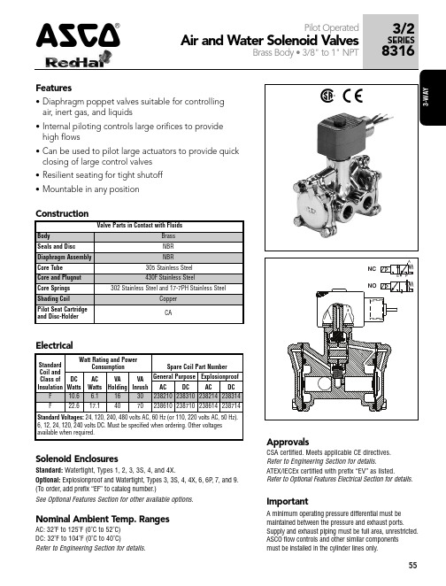
closing of large control valves • Resilient seating for tight shutoff • Mountable in any position
49
8316G024
2
17.1/F
22.6/F
3/4
17
4.1
0.7
10
9
9
9
82
49
8316G074
3
6.1/F
10.6/F
3/4
17
4.1
0.7
17
17
17
17
82
49
8316G044
4
17.1/F
22.6/F
1
25
11
0.7
10
9
9
9
82
49
8316G034
5
6.1/F
10.6/F
NORMALLY OPEN (Open when de-energized)
10
250
250
250
250
180
120
8316G016
2
17.1/F
22.6/F
1/2 5/8 3.2
10
150
125
125
125
180
120
8316G066
1
6.1/F
10.6/F
1/2 5/8 3.2
10
250
250
250
250
180
AEG LTH 56600系列产品说明书
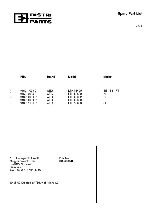
Market
BE - ES - PT NL DE GB SE
AEG Hausgeräte GmbH Muggenhoferstr. 135 D-90429 Nürnberg Germany Fax +49 (0)911 323 1420
Publ.No.: 599505958
19.05.99 Created by TDS web client 0.9
ABCDE ABCDE ABCDE ABCDE ABCDE ABCDE ABCDE ABCDE ABCDE ABCDE ABCDE ABCDE ABCDE A- - - - B- - - - C- ----E - - - DABCDE ABCDE ABCDE - - C- A- - - A- - - - B- - ----E - - - D-
Spare Part List
4546
PNC
Brand
A
916014090 01
B
916014094 01
C
916014096 01
D
916014099 01
E
916014104 01
AEG AEG AEG AEG AEG
Model
LTH 56600 LTH 56600 LTH 56602 LTH 56600 LTH 56600
Model LTH 56600 LTH 56600 LTH 56602 LTH 56600 LTH 56600
Exploded View No.:1708A05
Pos
120 130 305 305A 308 311 311A 328 328A 328B 344 500 510 510A
523 563 563A 999
AWA5680使用说明书V1.3
AWA5680型多功能声级计使用说明书目录1.概述 (1)2.主要特点 (1)3. 主要性能指标 (1)4. 结构特征 (3)5.符号、缩写定义 (4)6.按键 (5)7.主要显示界面 (5)7.1主菜单 (5)7.2测量界面 (5)7.2.1 单次测量界面 (6)7.2.2 24小时自动测量界面 (7)7.2.3 GPS定位界面 (8)7.3设置界面 (8)7.4调阅界面 (9)7.5校准界面 (9)8.使用方法 (10)8.1参数设置 (10)8.1.1 日历时钟调整 (10)8.1.2 测量时间设置 (10)8.1.3 频率计权的设定 (10)8.1.4 存贮模式的设定 (10)8.1.5 启动延时 (10)8.1.6 LCD显示对比度调节 (10)8.1.7 SMS设置 (10)8.2噪声单次测量 (11)8.324小时自动监测 (11)8.4简易机场噪声测量 (11)8.5数据调阅 (12)8.5.1积分测量结果的调阅 (12)8.5.2单次测量结果的调阅 (12)8.5.3 24小时自动监测结果的调阅 (12)8.5.4 记录结果的调阅 (13)8.5.5 GPS定位数据的调阅 (13)8.6数据打印 (14)8.6.1 单次测量结果的单组打印 (14)8.6.2 单次测量结果的多组打印 (15)8.6.3 24小时测量结果打印 (15)8.7保存结果的总清 (16)8.8校准 (16)8.8.1 采用AWA6221(B)进行声校准 (16)8.8.2 用活塞发声器进行校准 (16)8.8.3 直接输入灵敏度级 (16)9. 可选功能 (17)10.测量范围及本机噪声修正 (17)11. 过载指示 (17)附录一:装箱清单(标准配置) (18)附录二指向性响应 (19)附录三自由场响应 (20)附录四延伸电缆的影响 (21)附录五:GPS定位系统简介 (22)更改记录及版本说明注意事项1、第一次使用仪器前,请仔细阅读该说明书。
AWA5661型声级计操作规程
AWA5661-2型声级计操作规程1主要技术指标及参数配置号 AWA5661-2 传声器型号 AWA14425灵敏度级 -30dB频率计权 A、C、Z时间计权 F、S、I、Peak频率范围 10Hz~20 kHz测量上限 >140dB本机噪声 <20dBA符合标准 GB3785 1级显示器 128×64 主要主菜单 测量、设置、信息输出接口 AC、DC、RS232采样频率 48kHz积分功能 有积分测量时间 手动、10s、1m、5m、10m、20m、30m、1h、2h、4h、8h、12h、16h、24h分档可选。
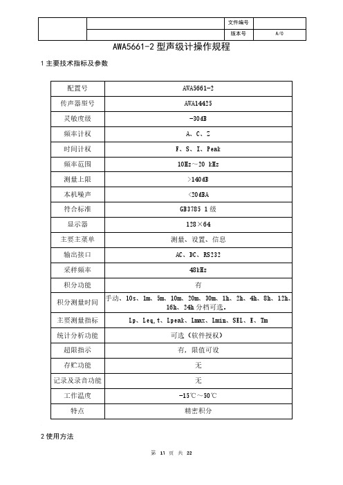
主要测量指标 Lp、Leq,t、Lpeak、Lmax、Lmin、SEL、E、Tm 统计分析功能 可选(软件授权)超限指示 有,限值可设存贮功能 无记录及录音功能 无工作温度 -15℃~50℃特点 精密积分2使用方法2.1操作界面按开机键后,仪器显示如下:主菜单下有四个子菜单:a)测量:噪声测量界面;b)设置:对交流输出、串行口、门限等进行设置;c)信息:显示出仪器的相关信息;d)校准:对仪器进行声学校准;2.2醒目测量界面光标移到“1.测量”上按进入键,仪器显示如下:显示器中间显示测量结果,其后显示所用频率计权及时间计权;最下一行从左到右分别显示电源电压,显示指标名,量程,工作状态。
光标可在“醒目”,“Lp”、“L”、“F“、”A“上移动。
每次开机后仪器的频率计权为A计权,时间计权为F计权,量程为低。
2.3列表测量界面光标移到“醒目”上按参数加键,进入列表测量界面显示如下:光标可在“列表”,“A”、“F”、“L”、“Ts”上移动。
2.4统计分析界面光标移到“列表”上按参数加键,进入统计分析界面,显示如下:当没有启动测量时,所有测量指标后均显示“---.-”,如想进行统计分析可按进入键,显示变成下图:统计界面下,光标可以在“统计”、“A”、“F”、“Ts“上移动。
统计分析功能为选配功能,如果没有统计分析功能的授权则提示如下:2.5A计权声压级测量将声级计头部传声器指向被测声源,尽量使声波从声级计的参考方向入射到传声器。
- 1、下载文档前请自行甄别文档内容的完整性,平台不提供额外的编辑、内容补充、找答案等附加服务。
- 2、"仅部分预览"的文档,不可在线预览部分如存在完整性等问题,可反馈申请退款(可完整预览的文档不适用该条件!)。
- 3、如文档侵犯您的权益,请联系客服反馈,我们会尽快为您处理(人工客服工作时间:9:00-18:30)。
AWA5661型声级计使用说明书® ®杭州爱华仪器有限公司2011年6月注意事项1、第一次使用仪器前,请仔细阅读该说明书。
2、测试传声器的膜片破损不在保修范围之内。
3、其它因使用不当造成的损坏不在保修范围之内。
4、电池应选用高性能碱性电池,该电池不能充电。
不使用时,请将电池取出,以免电池漏液造成仪器损坏。
电池不在保修范围内。
5、仪器需要维修时请带保修单。
11、概述 (1)2、主要技术性能 (1)3、结构及功能 (5)4、使用方法 (8)4.1 使用前的准备 (8)4.2 风罩的使用 (9)4.3 外接电源 (9)4.4电池检查及更换电池 (9)5、校准 (9)5.1声校准 (10)5.2 校准设置 (10)5.3 校准记录列表显示 (11)6、配置1的操作说明 (12)6.1操作界面 (12)6.2 A计权声压级测量 (12)6.3 C计权声压级测量 (13)6.4 时间计权的选择 (13)6.5 最大声级(Lmax)测量及取消 (13)6.6 峰值声压级(Lpeak)测量 (13)6.7 量程调节 (13)6.8 仪器设置 (14)6.8.1 交流输出幅度的调节 (14)6.8.2 交流输出用频率计权的选用 (15)6.8.3 自动关机功能 (15)6.8.4 超限报警功能 (15)6.8.5 串行口波特率 (16)6.8.6 保存仪器设置 (16)6.9 仪器信息 (16)27、配置2的操作说明 (16)7.1操作界面 (16)7.1.1 醒目测量界面 (17)7.1.2 列表测量界面 (17)7.1.3 统计分析界面 (18)7.2 A计权声压级测量 (19)7.3 C计权声压级测量 (19)7.4 时间计权的选择 (19)7.5 最大声级(Lmax)测量及取消 (19)7.6 峰值声压级(Lpeak)测量 (19)7.7 量程调节 (20)7.8 仪器设置 (20)7.8.1 交流输出幅度的调节 (20)7.8.2 交流输出用频率计权的选用 (21)7.8.3 自动关机功能 (21)7.8.4 超限报警功能 (21)7.8.5 串行口波特率 (22)7.8.6 保存仪器设置 (22)7.9 仪器信息 (22)8、配置3的操作 (23)8.1 主菜单 (23)8.2醒目测量界面 (23)8.3 列表测量界面 (24)8.4 设置1 (24)8.4.1 设置1第1页 (24)8.4.2设置1第2页 (26)8.4.3设置1第3页 (27)8.4.4 设置1第4页 (27)8.5 设置2子菜单 (28)38.5.1 启动设置 (28)8.5.2 自动暂停/再启动设置 (31)8.5.3 硬件设置 (31)8.5.4 日历时钟调节 (34)8.5.5记录设置 (34)8.5.6 录音设置 (35)8.6 数据管理子菜单 (36)8.6.1 数据调阅 (36)8.6.2 总清数据 (38)8.6.3 转为U盘模式 (38)8.7 仪器信息 (39)附录1:传输协议(区分大小写) (41)附录A:AWA14425型测试电容传声器在参考方向上的标称自由场响应 (44)附录B:在近似参考环境条件下声级计在参考方向上的标称自由场响应 (45)附录C:声级计在不同入射方向时的自由场响应 (46)附录D:装上SR35×60风罩后,在没有风时声级计在不同方向上的标称自由场响应 (47)附录E:指向设为90时的Z计权响应 (48)附录F:AWA5661带延伸线缆对测试的影响 (49)附录H:名词术语 (51)1.仪器显示常见符号及术语 (51)2. 常用声学测量指标的定义 (52)附件I:装箱清单 (57)1、概述AWA5661型声级计是一种模块化、多功能声级计,其性能符合GB/T3785-2010和IEC61672:2002标准对1级声级计的要求,对射频场敏感度属X类。
本仪器由于采用了先进的数字检波技术,使得仪器的稳定性、可靠性大大提高。
而且动态范围大、操作简单、用途广。
外壳采用ABS工程塑料,外形美观,重量轻,便于携带;电池供电,功耗小; RS-232数字输出接口,可以和计算机联机进行远程遥控遥测,也可多台声级计组网,用计算机控制同时进行测量。
本仪器可以广泛用于各种机器、车辆、船舶、电器等工业噪声测量和环境噪声测量,尤其是可以用于测量脉冲噪声。
适用于工厂企业、环境保护、劳动卫生、教学、科研等领域。
AWA5661型声级计有多个品种。
它们的结构及工作原理相同,只是测试传声器及软件授权不相同。
2、主要技术性能(1)传声器:Φ12.7mm(1/2")测试电容传声器,自由场响应,参考点为传声器膜片中心,它们在参考方向的标称自由场响应见附录A。
用户也可选配其它型号的传声器,可以用来测量特别低的噪声或特别高的噪声等。
可配传声器性能表传声器型号外径(mm)标称灵敏度(mV/Pa)频率范围(Hz)AWA14425 Φ12.730 10~16000 AWA14423 Φ12.740 10~20000 AWA14411 Φ23.7780 10~16000 AWA14431 Φ6.35 4 10~2000012 (2) 动态范围所配传声 器型号 A 计权 本机噪声 C 计权 本机噪声 Z 计权本机噪声 测量上限AWA14425 <20dB(A) <25dB(C) <30dB 140dBAWA14423 <18dB(A) <23dB(C) <28dB 138dBAWA14411 <10dB(A) <15dB(C) <20dB 132dBAWA14431 <40dB(A)<45dB(C) <50dB 160dB(3) 频率范围:10Hz ~16kHz ,当配AWA14423或AWA14431型传声器时频率范围可达到10Hz ~20kHz (4) 频率计权:A 计权,C 计权,Z 计权,在自由场中响应见附录B(5) 时间计权:F (快),S (慢),I (脉冲),Peak(峰值)(6) 检波器特性:真有效值,数字检波,峰值因数≥10(7) 仪器精度:符合IEC61672 1级或GB/T3785 1级(8) 量程控制:手动,高、低两档,每档20dB 衰减,参考级量程线性范围>95dB 。
(9) 总量程范围:(对1kHz 频率) 以上量程是出厂时的值,当用户调过校准值或更换传声器型号量程 测量范围 (dB ) 峰值因数10时(dB ) 峰值测量范围(dB ) AWA14425高 45~140 45~123 70~143 低 27~120 27~103 50~123 AWA14423高 43~138 43~121 70~141 低 25~80 25~101 50~121 AWA14411高 35~132 35~115 60~135 低 15~112 15~95 40~115 AWA14431 高65~160 65~143 90~163 低 45~140 45~123 70~143过传声器时,量程可能有所变化,具体范围在量程高时由过载指示和下限指示决定;在量程低时,测量上限由过载指示决定,下限由本底噪声再加8dB决定。
(10) 显示:128×64点阵OLED。
(11) 输出接口:交流输出,直流输出,RS-232C。
(12) 校准:使用1级声级校准器或活塞发声器。
(13) 电源:内部用4×LR6(5#)碱性电池,可连续工作16小时。
外接电源4.5V~9V,0.2A。
(14) 外形尺寸:220 mm×72 mm×32 mm(15) 质量:400g。
(16) 使用条件:气温:-15℃~50℃相对湿度:10% ~90%气压:65kPa~108kPa3不同配置对比表配置号 1 2 3 频率计权A,C,Z A,C,Z A,C,Z时间计权F,S,I,Peak F,S,I,PeakF,S,I,Peak主要子菜单测量设置信息校准测量设置信息校准测量设置1设置2数据校准信息输出接口AC(三档可调)DCRS232 AC(三档可调)DCRS232AC(三档可调)DCRS232积分功能无有有统计分析无无有日历时钟无无有主要测量指标Lp、Lpeak、LmaxLp、Lpeak、Lmax、Lmin、SEL、ELFp、LSp、LIp、Leq,t、Lpeak、Leq,T、LFmax、LFmin、LSmax、LSmin、LImax、LImin、SEL、Lex8h、LAVG、TWA、DOSE、Ln1、Ln2、Ln3、Ln4、Ln5、SD、Ts、Tm、Volt、E.USB接口无无有存贮功能无无有注1:Ln1、Ln2、Ln3、Ln4、Ln5中的n1可以在1到99之间选取。
4注2:配置3可以选配记录及录音功能。
记录时间计权声压;短时等效声级随时间的变化曲线;录制WAV格式的声音文件,采样频率48kHz、24kHz、12kHz。
3、结构及功能声级计的外形见图1,它由传声器、前置放大器和主机组成。
正常工作时应将测试电容传声器和前置放大器安装于主机头部,通过滚花螺母可将它们从声级计上取下,加上延伸电缆线,加入延伸电缆后对测量的影响见附录E。
前置级和声级计之间插座引脚功能见图2。
声级计的外形呈尖形,以减小对声波的反射。
声级计外壳引起反射的标称影响及在不同入射方向时声级计的指向特性见附录C。
外壳用ABS塑料注塑而成,电池装在电池盒内,取下电池盖板可很方便的更换电池。
测量结果由128×64点阵OLED显示。
过载指示灯位于正面上方。
声级计的下方底部有一个9芯插座,引脚的定义及用途如图3。
5电容传声器前置放大器过载指示灯显示器按键输出插座外接电源接口指示灯USB指示灯复位按钮图167按键主要功能开机键,打开仪器电源进入键,进入下一级菜单或确认操作退出键,退到上一级菜单或关闭电源光标键,将光标移到下一个位置光标键,将光标移到上一个位置参数键,光标所在处的参数加参数键,光标所在处的参数减复位键,让仪器内部的单片机复位图2图31.电源:+4.5V~9V2.RXD3.TXD4.交流输出5.电源地6.直流输出7.空8.电源控制:平时应悬空,加高电平时将打开仪器电源。
9.复位:平时应悬空,加高电平时仪器将复位。
主要符号意义显示指示的状态电源电压的高低传声器设置为扩散场型正在积分测量及统计分析积分测量及统计分析被暂停正在记录声压级随时间的变化曲线正在进行录音被测信号的峰值超过测量上限。
被测信号的幅度低于测量下限4、使用方法4.1 使用前的准备(1) 检查电容传声器和前置放大器是否已安装好。
(2) 检查电池是否已装好,如未安装则应推开声级计背面电池盖板,按正确极性安装好电池。
