2009年全球粗钢产量同比下降8%
徕卡TS09使用说明
徕卡TS09使用说明作为世界上著名的高端相机品牌,徕卡的镜头一直以来都备受业界赞誉。
其中,TS(Tilt Shift)系列镜头特别受到建筑、风景等摄影爱好者的青睐,因为它通过倾斜和移动镜头,可以使图像产生更多的特殊效果和视觉感受。
在TS系列中,TS09是一款非常实用的镜头,今天我为大家介绍一下它的使用方法。
镜头基本结构TS09是一款倾斜移位变焦镜头,它由镜头本体、光圈环、聚焦环、移位轴、倾斜轴、变焦环等部分组成。
在掌握使用方法之前,需要先了解一下这些部分的作用。
- 镜头本体:是镜头的主体,负责物体成像。
- 光圈环:是控制镜头光圈大小的部分,可以用来控制景深和曝光量。
- 聚焦环:用来调节镜头的聚焦距离,不同的聚焦距离能够带来不同的景深效果。
- 移位轴:使镜头在水平或垂直方向上移位,可以调整景深和透视效果。
- 倾斜轴:使镜头在水平或垂直方向上倾斜,可以消除或加强景深的效果。
- 变焦环:用来调节镜头的焦距,可以变化所拍摄的视角。
使用方法1. 调节光圈和聚焦距离在拍摄一张图片之前,需要先设置好镜头的光圈和聚焦距离。
调节光圈可以通过光圈环进行,将光圈设置到更大的值可以使景深变浅,将光圈设置到更小的值可以让景深变得更深。
聚焦距离可以通过聚焦环进行调节,将聚焦距离设置到近景模式下可以拍摄出清晰的近景,将聚焦距离设置到远景模式下则可以拍摄出清晰的远景。
2. 移位和倾斜当需要拍摄有明显透视效果的建筑或其他高大的物体时,可以通过移位和倾斜来进行调整。
首先要对镜头进行水平或垂直方向的移位,在适当的光圈和聚焦距离下,可以使镜头拍摄出更加真实、大气的照片。
在倾斜方面,可以通过调节倾斜轴来消弭景深效果,或者增强景深效果,从而达到更好的照片效果。
3. 变焦变焦是用来调节焦距的,可以用来变化所拍摄的视角。
通过调节变焦环可以在视觉上抵近物体或者使其远离我们,拍摄出更加生动、多变的照片。
需要注意的是,通过变焦调节镜头视角时需要调节光圈,因为调节焦距会影响光线的进射角,若不慎会影响景深。
Mellanox MMA2P00-AS MMA2P00-ASHT 25GbE SFP28 光纤传输器

Mellanox® MMA2P00-AS/MMA2P00-ASHT is a pluggable SFP28 optical transceiver designed foruse in 25GbE Ethernet. It incorporates Mellanox integrated circuit technology in order to provide highperformance at low power. The transceiver operates over a pair of multi-mode fibers (MMF), using anominal wavelength of 850nm, and is SFF-8402 compliant.MMA2P00-AS/MMA2P00-ASHT has a standard SFP28 connector on the electrical side towards the hostsystem supporting IEEE 802.3bm. The optical interface is composed of two optical channels/fibers, onein each direction, intended for a multi-mode optical cable connected via standard LC connectors. Eachchannel/fiber operates at signaling rates up to 25.78125GBd.The transceiver offers selectable retiming for both its optical transmitter and receiver for the 25Gb/s rate,and it also supports lower bit rates without. The transmitter has programmable input equalizers and inputsquelch function, while the receiver has programmable output amplitude and pre-emphasis.Rigorous production testing ensures the best out-of-the-box installation experience, performance, anddurability.T able 1 - Absolute Maximum RatingsT able 2 - Operational Module InformationNotes: 1. Internal temperature readout through DDMI of up to 75°C is allowed. 2. Internal temperature readout through DDMI of up to 90°C is allowed.MMA2P00-AS | MMA2P00-ASHT25GbE SR SFP28 MMF Optical Transceiver†PRODUCT BRIEFINTERCONNECT©2019 Mellanox Technologies. All rights reserved.†For illustration only. Actual products may vary.350 Oakmead Parkway, Suite 100, Sunnyvale, CA 94085Tel: 408-970-3400 • Fax: © Copyright 2019. Mellanox Technologies. All rights reserved.Mellanox and Mellanox logo are registered trademarks of Mellanox Technologies, Ltd.LinkX is a trademark of Mellanox Technologies, Ltd. All other trademarks are property of their respective owners.Mellanox 25GbE SR SFP28 MMF T ransceiverpage 2Warranty InformationMellanox LinkX optical transceivers include a 1-year limited hardware warranty, which covers parts repair or replacement.Mechanical Schematics53911PB Rev 1.22Table 3 - Part Number and Description。
NEO-M8_ProductSummary_(UBX-13003449)
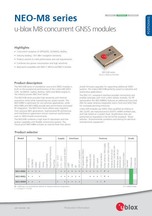
12.2 x 16.0 x 2.4 mm
Product description
The NEO-M8 series of standalone concurrent GNSS modules is built on the exceptional performance of the u-blox M8 GNSS (GPS, GLONASS, Galileo, BeiDou, QZSS and SBAS) engine in the industry proven NEO form factor. The NEO-M8 series provides high sensitivity and minimal acquisition times while maintaining low system power. The NEO‑M8M is optimized for cost sensitive applications, while NEO‑M8N and NEO-M8Q provide best performance and easier RF integration. The NEO form factor allows easy migration from previous NEO generations. Sophisticated RF-architecture and interference suppression ensure maximum performance even in GNSS-hostile environments. The NEO‑M8 combines a high level of robustness and inte gration capability with flexible connectivity options. The future-proof NEO‑M8N includes an internal Flash that allows simple firmware upgrades for supporting additional GNSS systems. This makes NEO‑M8 perfectly suited to industrial and automotive applications. The DDC (I2C compliant) interface provides connectivity and enables synergies with most u‑blox cellular modules. For RF optimization the NEO‑M8N/Q features an additional front-end LNA for easier antenna integration and a front-end SAW filter for increased jamming immunity. u-blox M8 modules use GNSS chips qualified according to AEC‑Q100, are manufactured in ISO/TS 16949 certified sites, and fully tested on a system level. Qualification tests are performed as stipulated in the ISO16750 standard: “Road vehicles – Environmental conditions and testing for electrical and electronic equipment”.
AFUWIN

AMIBIOS8 ROM Utility User GuideAFUWINDocument Revision 1.0.1 – Aug 28, 2009NDA REQUIREDCopyright (c) 2008 American Megatrends, Inc.All Rights Reserved.American Megatrends, Inc.5555 Oakbrook ParkwaySuite 200Norcross, GA 30093This publication contains proprietary information which is protected by copyright. No part of this publication may be reproduced, transcribed, stored in a retrieval system, translated into any language or computer language, or transmitted in any form whatsoever without the prior written consent of the publisher, American Megatrends, Inc. American Megatrends, Inc. retains the right to update, change, modify this publication at any time, without notice. For Additional InformationCall American Megatrends BIOS Sales Department at 1-800-828-9264 for additional information.Limitations of LiabilityIn no event shall American Megatrends be held liable for any loss, expenses, or damages of any kind whatsoever, whether direct, indirect, incidental, or consequential, arising from the design or use of this product or the support materials provided with the product.Limited WarrantyNo warranties are made, either express or implied, with regard to the contents of this work, its merchantability, or fitness for a particular use. American Megatrends assumes no responsibility for errors and omissions or for the uses made of the material contained herein or reader decisions based on such use.Trademark and Copyright AcknowledgmentsAll product names used in this publication are for identification purposes only and are trademarks of their respective Companies.DisclaimerThis manual describes the operation of the AMIBIOS8 ROM Utilities. Although efforts have been made to insure the accuracy of the information contained here, American Megatrends expressly disclaims liability for any error in this information, and for damages, whether direct, indirect, special, exemplary, consequential or otherwise, that may result from such error, including but not limited to the loss of profits resulting from the use or misuse of the manual or information contained therein (even if American Megatrends has been advised of the possibility of such damages). Any questions or comments regarding this document or its contents should be addressed to American Megatrends at the address shown on the cover.American Megatrends provides this publication “as is” without warranty of any kind, either expressed or implied, including, but not limited to, the implied warranties of merchantability or fitness for a specific purpose.Some states do not allow disclaimer of express or implied warranties or the limitation or exclusion of liability for indirect, special, exemplary, incidental or consequential damages in certain transactions; therefore, this statement may not apply to you. Also, you may have other rights which vary from jurisdiction to jurisdiction.This publication could include technical inaccuracies or typographical errors. Changes are periodically made to the information herein; these changes will be incorporated in new editions of the publication. American Megatrends may make improvements and/or revisions in the product(s) and/or the program(s) described in this publication at any time. Requests for technical information about American Megatrends products should be made to your American Megatrends authorized reseller or marketing representative.Revision InformationOverviewAFUWIN is an updating system BIOS utility with command line and GUI interface. It has same parameters and behavior as AFUWIN, and further, GUI feature starting from v4.10can provide you a friendly environment to visualize BIOS update procedure. By the way, do not forget that target board MUST be AMIBIOS system while using this utility. FeaturesThis utility offers the following features:•Small executable file size•Quickly update•Clear updating information and status•Fully compatible with previous version (See Appendix B AFUWIN v3.xx Commands)RequirementsSupported Operating SystemAFUWIN Utility is supported in following operating system:•Microsoft® Windows® 98•Microsoft® Windows® ME•Microsoft® Windows® 2000•Microsoft® Windows® NT 4.0•Microsoft® Windows® XP/XP64•Microsoft® Windows® PE•Microsoft® Windows® Vista 32/64•Microsoft® Windows® PE 2.0 x64 (AFUWINx64.EXE)•Microsoft® Windows® 7 32/64BIOS RequirementsSystem BIOS should have the followings:•AMIBIOS CORE version 8.xx.xx.•SMIFlash eModule with “8.00.00_SMIFlash-1.00.07” label or later.•Token: SDSMGR_IN_RUNTIME = ON.•Token: SMI_INTERFACE_FOR_SDSMGR_FUNC = ON.Operating System Driver RequirementsFollowing drivers for different operation system are required by this utility:•UCOREVXD.VXD Driver for Microsoft® Windows® 98/ME•UCORESYS.SYS Driver for Microsoft® Windows® NT/2000/XP/PE•UCOREW64.SYS Driver for Microsoft® Windows® XP64 Getting StartedInstallationCopies AFUWIN.EXE, AFUWINx64.EXE (for Microsoft Windows PE 2.0 x64),UCOREVXD.VXD, UCORESYS.SYS and UCOREW64.SYS to any storage locationaccessible by the host system and then run AFUWIN in command prompt. Rememberthat three files MUST be in same directory. For launching GUI mode, you can justdouble-click on the icon.UsageFor previous usage, see Appendix B AFUWIN v3.xx Commands to know details.AFUWIN <BIOS ROM File Name> [Option 1] [Option 2]……….OrAFUWIN <Output BIOS ROM File Name> <Commands>OrAFUWIN /M<MAC Address>OrAFUWIN /MAIBIOS ROM File NameThe mandatory field is used to specify path/filename of the BIOS ROM filewith extension.CommandsThe mandatory field is used to select an operation mode:•/O Save current ROM image to file•/U Get and display ROM ID from ROM file•/Ln Refer to option: /Ln•/M <MAC Address>Refer to option: /M•/MAI Display current system and ROM file's MA•/HOLE Update specific ROM hole by given name•/HOLEOUT Save specific ROM holedata by given name•/D Verification test of given ROM file withoutflashing•/EC Flash EC firmware BIOS (Refer to OFBDspec)Path: $BIOS/Corebin/800/ROMUtils/On FlashBlock Description Specification.PDF.Sample Code Module Path:$BIOS/Examples/On Flash Block Description •/NCB Flash NCB data by given name•/NCBOUT Output NCB data by given name•/C Destroy CMOS checksumOptionsThe optional field used to supply more information for flashing BIOS ROM.Following lists the supported optional parameters and format:•/P Program main bios image•/B Program Boot Block•/N Program NVRAM•/C Destroy CMOS after update BIOS done•/E Program Embedded Controller block if present •/K Program all non-critical blocks•/Kn Program n’th non-critical block only (n=0 – 7)•/Q Quiet mode enable•/REBOOT Reboot after update BIOS done•/X Do not check ROM ID•/S Display current system’s BIOS ROM ID•/Ln Load CMOS default (n=0 - 1)▪L0: Load current CMOS optimal settings▪L1: Load current CMOS failsafe settings▪L2: Load CMOS optimal settings from ROMfile▪L3: Load CMOS failsafe settings from ROMfile•/M<MAC Address>Update BootBlock MAC address if exists•/R Preserve all SMBIOS structures duringNVRAM programming•/Rn Preserve specific SMBIOS structure duringNVRAM programming•/ECUF Update EC BIOS when newer version isdetected.•/ShutDown Shutdown system after programming.•/clnevnlog Clean Event Log.•/DeDftCfg Delete all default settings from BIOS.•/-Command Name Delete certain command’s default setting.[OEM Uses Only.]•/MEUF Update Intel ME ignition firmware.•/ME Update entire Intel ME region.(WinPE only)Note : Running AFUWIN under command prompt directly will display help message.ExamplesExamples on how to update BIOS using the command prompt are shown infollowing:•Save current BIOS ROM to fileAFUWIN <BIOS ROM File Name> /O•Get and display ROM ID from BIOS ROM fileAFUWIN <BIOS ROM File Name> /U•Update main BIOS image onlyAFUWIN <BIOS ROM File Name>OrAFUWIN <BIOS ROM File Name> /p•Update Boot Block onlyAFUWIN <BIOS ROM File Name> /B•Update NVRAM onlyAFUWIN <BIOS ROM File Name> /N•Update Embedded Controller Block onlyAFUWIN <BIOS ROM File Name> /E•Update Embedded Controller Block if newer version is detected AFUWIN <BIOS ROM File Name> /ECUF•Update 2nd non-critical block onlyAFUWIN <BIOS ROM File Name> /K2•Update main BIOS image, Boot Block and NVRAM at onceAFUWIN <BIOS ROM File Name> /P /B /N•Update whole BIOS ROMAFUWIN <BIOS ROM File Name> /P /B /N /C /E /K•Update whole BIOS ROM and load current CMOS optimal settings AFUWIN <BIOS ROM File Name> /P /B /N /C /E /K /L0•Update whole BIOS without checking ROM IDAFUWIN <BIOS ROM File Name> /P /B /N /C /E /K /X•Update whole BIOS with quiet executionAFUWIN <BIOS ROM File Name> /P /B /N /C /E /K /Q•Update whole BIOS in quiet mode and REBOOT quietlyAFUWIN <BIOS ROM File Name> /P /B /N /C /E /K /Q /REBOOT•Update BootBlock MAC addressAFUWIN /M<MAC Address>•Update whole BIOS and BootBlock MAC addressAFUWIN <BIOS ROM File Name> /P /B /N /C /E /K /M<MAC Address>•Update whole BIOS except existing SMBIOS structuresAFUWIN <BIOS ROM File Name> /P /B /N /C /E /K /R•Update whole BIOS but preserve SMBIOS type 0 and 11AFUWIN <BIOS ROM File Name> /P /B /N /C /E /K /R0 /R11•Update dedicate ROM Hole AreaAFUWIN <ROM Hole File Name> /Hole:Name•Update dedicate NCB AreaAFUWIN <NCB File Name> /NCB:Name•Output dedicate ROM Hole FileAFUWIN <Output ROM Hole File Name> /HOLEOUTt:Name•Output dedicate NCB FileAFUWIN <Output NCB File Name> /NCBOUT:Name•Cancel Embedded AFU default commands- Below sample cancels B & P commands if BIOS has embedded B & P commands in OFBD.AFUWIN <BIOS ROM File Name> /-B /-PNotice: if /p & /b are set as default command only and /-B /-P commands are issued then P command will still be issued because if none of command is issued then /p will still issue as AFU default.•Cancel ALL Embedded AFU default commandsAFUWIN <BIOS ROM File Name> /DeDftCfgMain WindowButtonsClick this button to search for BIOS ROM file from any disk drive.Click this button to starting update BIOS.Click this button to save BIOS ROM image to disk drive.Click this button to exit this program.Function FrameInformation TabThis tab displays system BIOS information for your reference before flashingBIOS.FieldSetup TabThis tab allows you to change the settings for flashing BIOS.FieldFailsafe BIOS after flashing.Select to destroy CMOS checksum after flashing.Destroy CMOSThis is default setting in CMOS Option block.CheksumThis tab displays the updating status.FieldFunctionsTo launch into AFUWIN with GUI mode, you can double-click the executable file icon to open the operating window:Usually, system BIOS information will be displayed first, but you may see a pop-up dialog if the system does not support AMIBIOS update function. After open this program successfully, you can refer to following steps to finish the operation what you need: Saving system BIOS ROM image to file1.Press <Save> button to open file dialog box.2.Select path and input a file name.3.Click on OK button to save system BIOS ROM image into specific file.4.Press <Exit> button to exit this program.Flashing system BIOS with given file1.Press <Open> button to search for BIOS ROM image file from any disk driver andload it into memory.2.Switch to Setup Tab to check and change necessary settings.3.Press <Flash> button to start the operation.4.Progess Tab will be switched automatically and display the programming status.5.After BIOS updated, you can press <Exit> button to exit this program or systemwill restart automatically if the Restart After Programming option enabled. Error Code ListAppendix B : AFUDOS v3.xx CommandsUsage : AFUDOS /i<ROM File Name> [/o<Save ROM File Name>] [/n] [/p[b][n][c][e]][/s] [kN] [/c[N]] [/q] [/h] [/t] [/u[ROM File Name]]Following table lists the description of previous version of AFUDOS commands.。
联想Tab M8产品说明书
Lenovo T ab M8Safety, Warranty & Quick Start Guide Lenovo TB-8705FLenovo TB-8705XRead this guide carefully before using your device.All information labeled with * in this guide only refers to the WLAN + LTE model.Reading before using your deviceReading first - regulatory informationDevice models equipped with wireless communications comply with the radio frequency and safety standards of any country or region in which it has been approved for wireless use. In addition, if your product contains a telecom modem, it complies with the requirements for connection to the telephone network in your country.Be sure to read the Regulatory Notice for your country or region before usingthe wireless devices contained in your device. To obtain a PDF version of the Regulatory Notice, go to https://.Getting supportTo get support on network services and billing, contact your wireless network operator. To learn how to use your device and view its technical specifications, go to https://.Accessing your User GuideYour User Guide contains detailed information about your device. To download the publications for your device, go to https:// and follow the instructions on the screen.Legal noticesLenovo and the Lenovo logo are trademarks of Lenovo in the United States, other countries, or both.Other company, product, or service names may be trademarks or service marks of others.Manufactured under license from Dolby Laboratories. Dolby, Dolby Audio, and the double-D symbol are trademarks of Dolby Laboratories.LIMITED AND RESTRICTED RIGHTS NOTICE: If data or software is delivered pursuant a General Services Administration “GSA” contract, use, reproduction,or disclosure is subject to restrictions set forth in Contract No. GS-35F-05925.Device overview1Card tray2Headset connector3Speaker4Proximity sensor5Front camera6Volume buttons7Power button8T ouch screen9Micro USB connector10Microphone11Rear camera12Flashlight• T he WLAN version does not have a Nano-SIM card slot.• All pictures and illustrations in this document are for your reference only andmay differ from the final product.Preparing your deviceInstalling cardsInstall the cards as shown in the figure.Power off the device before inserting or removing a card.Note that the WLAN version does not have a Nano-SIM card slot.Charging your deviceConnect your device to a poweroutlet using the USB cable andpower adapter provided.Turning onPress and hold the Power button untilthe Lenovo logo appears.Important safety and handling informationPlastic bag noticeDanger: Plastic bags can be dangerous. Keep plastic bags away from babies and children to avoid danger of suffocation.Caution about high volume usageWarning: Exposure to loud noise from any source for extended periods of time may affect your hearing. The louder the sound, the less time is required before your hearing could be affected. To protect your hearing:• Limit the amount of time you use headsets or headphones at high volume.• Avoid turning up the volume to block out noisy surroundings.• Turn the volume down if you can’t hear people speaking near you.If you experience hearing discomfort, including the sensation of pressure or fullness in your ears, ringing in your ears or muffled speech, you should stop listening to the device through your headset or headphones and have your hearing checked.To prevent possible hearing damage, do not listen at high volume levels for long periods.Safety instructions for parents and adult supervisorsYour mobile device is not a toy. As with all electrical products, precautions should be observed during handling and using of electrical products to reduce the risk of electric shock. If parents choose to allow children to use the device, they should caution his or her child about the potential hazard while using and handling the mobile device.Parents should inspect the mobile device (including the ac power adapter andthe small part, as applicable) periodically for damage. Routinely check this mobile device to ensure that the device is working properly and is safe for children to use.Internal rechargeable battery warningDanger: Do not attempt to replace the internal rechargeable lithium ion battery. Replacing the original battery with an incompatible type may result in an increased risk of personal injury or property damage due to explosion, excessive heat, or other risks. Do not attempt to disassemble or modify the battery pack. Attempting to do so can cause a harmful explosion or battery fluid leakage.When disposing of the battery, comply with all relevant local ordinances or regulations. Do not dispose the battery pack in municipal waste. Dispose used batteries according to the instructions.The battery pack contains a small amount of harmful substances.To avoid injury:• Keep the battery pack away from open flames or other heat sources.• Do not expose the battery pack to water, rain, or other corrosive liquids.• Do not leave the battery in an environment with extremely high temperature.• Avoid short-circuiting the battery pack.• Keep the battery pack out of reach of small children and pets.• D o not leave the battery in an environment with extremely low air pressure. It may result in an explosion or the leakage of flammable liquid or gas from the battery. To extend battery life, we recommend charging the battery to at least 30% to 50% capacity each time, and recharging it every three months to prevent over discharge.Service and support informationThe following information describes the technical support that is available for your product, during the warranty period or throughout the life of your product. Refer to the Lenovo Limited Warranty (LLW) for a full explanation of Lenovo warranty terms. See “Lenovo Limited Warranty notice” later in this document for details on accessing the full warranty.Online technical supportOnline technical support is available during the lifetime of a product at:https://Telephone technical supportYou can get help and information from the Customer Support Center by telephone. Before contacting a Lenovo technical support representative, please have the following information available: model and serial number, the exact wordingof any error message, and a description of the problem.Your technical support representative might want to walk you through the problem while you are at your device during the call.Worldwide Lenovo Support telephone listImportant: Telephone numbers are subject to change without notice. The most up-to-date telephone list for the Customer Support Center is always available at: /support/phoneIf the telephone number for your country or region is not listed, contact your Lenovo reseller or Lenovo marketing representative.Warranty informationLenovo Limited Warranty noticeThis product is covered by the terms of the LLW, version L505-0010-02 08/2011. Read the LLW at /warranty/llw_02. You can read the LLW in a number of languages from this Web site. If you cannot view the LLW from the Web site, contact your local Lenovo office or reseller to obtain a printed version of the LLW.* Excludes some components. 90-day limited warranty for poweradapters,keyboards, plastics, and hinges.Type of warranty service1. Customer Replaceable Unit (“CRU”) Service2. On-site Service3. Courier or Depot Service4. Customer Carry-In Service5. Mail-in Service6. Customer Two-Way Mail-in Service7. Product Exchange ServiceFor a full explanation of the types of warranty service, refer to the full warranty. See “Lenovo Limited Warranty notice” for details on accessing the full warranty.If you need support for this device, do not go back to your point of purchase. Please visit https://, where you will find answers to frequently asked questions, software updates and details on how to get in touch with us. EurAsia compliance markEnvironmental, recycling, and disposal information General recycling statementLenovo encourages owners of information technology (IT) equipment to responsibly recycle their equipment when it is no longer needed. Lenovo offersa variety of programs and services to assist equipment owners in recycling theirIT products. For information on recycling Lenovo products, go to/recyclingImportant battery and WEEE informationRecycling and disposal information for Japan is available at:/recycling/japanAdditional recycling statementsAdditional information about recycling device components and batteries is in your User Guide. See “Accessing your User Guide” for details.Battery recycling marksBattery recycling information for TaiwanBattery recycling information for the United States and CanadaBattery recycling information for the European UnionRestriction of Hazardous Substances Directive (RoHS)TurkeyLenovo products sold in Turkey, on or after June 1, 2009, meet the requirements of the former Republic of Turkey Restriction of Hazardous Substances legislation from 30th of May 2008 and the Control of Waste Electrical and Electronic Equipment Regulations from 22nd of May 2012 (“Turkey RoHS”).UkraineLenovo products sold in Ukraine, on or after January 1, 2011, meet the requirements of the Technical Directive on Restriction of Hazardous Substances in Electricand Electronic Equipment enforced by the Government, Decision No 1057 dated 2008/12/03 (“Ukraine TR on RoHS”).IndiaLenovo products sold in India, on or after May 1, 2012, meet the requirements of the India E-waste (Management) Rules (“India RoHS”).VietnamLenovo products sold in Vietnam, on or after September 23, 2011, meet the requirements of the Vietnam Circular 30/2011/TT-BCT (“Vietnam RoHS”). European UnionLenovo Products meet the requirement of Directive 2011/65/EC on the restriction of the use of the certain hazardous substances in electrical and electronic equipment (“RoHS 2”). Lenovo products sold in the European Union, from the 21st July 2019, meet the requirement of Commission Delegated Directive (EU 2015/863) amending Directive 2011/65/EU. For more information about Lenovo progress on RoHS, go to: https:///us/en/social_responsibility/RoHS-Communication.pdf SingaporeLenovo products sold in Singapore, on or after June 1, 2017, meet the requirements of Government Gazette order No. S 263/2016 Restriction of Hazardous Substances in Electrical and Electronic Equipment in Singapore (“SG-RoHS”). European Union compliance statementEuropean Union conformityCompliance with the RE DirectiveLenovo PC HK Limited declares that the radio equipment type Lenovo TB-8705F ,Lenovo TB-8705X is in compliance with Directive 2014/53/EU.The full text of the EU declaration of conformity is available at the following internet address: https:///us/en/compliance/eu-doc.This radio equipment operates with the following frequency bands and maximum radio-frequency power:The above information is for EU countries only. Please refer to the actualproduct for supported frequency bands in other countries.Specific Absorption Rate informationYOUR MOBILE DEVICE MEETS INTERNATIONAL GUIDELINES FOR EXPOSURE TO RADIO WAVES.Your mobile device is a radio transmitter and receiver. It is designed not to exceed the limits for exposure to radio waves (radio frequency electromagnetic fields) recommended by international guidelines. The guidelines were developed by an independent scientific organization (ICNIRP) and include a substantial safety margin designed to assure the safety of all persons, regardless of age and health.The radio wave exposure guidelines use a unit of measurement known as the Specific Absorption Rate, or SAR. The SAR limit for mobile devices is 2W/kg. Tests for SAR are conducted using standard operating positions with the device transmitting at its highest certified power level in all tested frequency bands. The highest SAR values under the ICNIRP guidelines for your device model are listed below:During use, the actual SAR values for your device are usually well below the values stated. This is because, for purposes of system efficiency and to minimize interference on the network, the operating power of your mobile device is automatically decreased when full power is not needed for the data connection. The lower the power output of the device, the lower its SAR value.If you are interested in further reducing your RF exposure then you can easily doso by limiting your usage or simply using a hands-free kit to keep the device away from the body.©Copyright Lenovo 2019.V1.0_20190924711608030871MCPrinted in China。
2009款丰田RAV4整车装备技术信息指南

底盘
装备
车身
车身电气
进入及启动系统 – 仅携带钥匙即可完成手动锁门/开锁,发动机启动,行李箱门开
启
[钥匙]
[车门,后背门锁止/开锁功能]
19
[发动机启动系统]
Mo车de型l O概u述tline
发动机
底盘
车身
装备
座椅 – 驾驶员电动座椅及驾驶员和前乘客座椅加热器
车身电气
前垂直 SW 座椅滑动 SW
后垂直 SW
操纵杆
21
Mo车de型l O概u述tline
发动机
底盘
车身
装备
其它项目
项目 电动门锁 无线门锁遥控 控制系统
电动窗系统
滑动窗系统
说明 1级开锁 (没有2级开锁)
2-按钮
仅对驾驶侧车窗有单 触式自动上下 带防夹功能
对标准版是选配
发动机停机系统 防盗抢系统 巡航控制系统
标配
安全喇叭和自带电源 防盗喇叭
发动机
底盘
性能
动力传输
车身
车身电气
前轮主销后倾 前轮外倾 前轮前束 前轮主锁内倾
5° 50’ -0° 11’ 1 mm 11° 26’
11
轮胎规格
225/65R17
轮距(前后同) 1560
后轮外倾
-1° 04’
后轮前束
2.3 mm
Mo车de型l O概u述tline
性能
发动机
动力传输
[制动] 前: 通风盘:296X28mm
清洁空气 过滤器
车身电气
花粉
3分钟
花粉去除模式开关
17
Mo车de型l O概u述tline
发动机
底盘
图解2009款迈腾双离合器自动变速器

K1的外片支架
K2的外片支架
双质量飞轮
输入轴毂 主动盘片
主毂 图3双离合器结构
倒挡 6挡
5挡
动力输出
离合器1 离合器2 输入轴2
发动机 动力输入
输入轴1
分动器 动力输出
2挡 4挡
3挡 1挡
图7 DSG变速器内部机械系统构造1
K1的内片支架
活塞1 K1的油压腔
K1的外支架 离合器K1
输入轴
碟形弹簧 图4 离合器K1内部结构
44
·June
维修技巧
S E RV I C E Te c h n i c
传动机构2 多片式离合器K2
发动机扭矩
多片式离合器K1 传动机构1 图2 DSG变速器工作原理示意图
对他们调整控制,通过分离、接合不同的 离合器实现挡位的变换。1、3、5挡和倒 挡由离合器K1控制;2、4、6挡由离合器 K2控制。其原理是:发动机动力可通过2 个离合器传送给变速器。在汽车用1挡加 速时,一个离合器接合;此时2挡已经挂 上,但相应的另一个离合器未接合。当需 要换2挡而分离第一个离合器时,第二个 离合器会在同时接合,其它挡位的变化依 此类推。另外,变速器可随时根据速度的 变化趋势预选出合适的挡位,这样在降挡 时不会出现挡位选择不合理的现象。双离 合器的最大好处是可以实现动力的不间断 输出。每个挡位齿轮上都有同步齿套和挡 位变换元件。
靶轮
5挡
1/倒挡 3挡
图9 输入轴结构图
靶轮
G195 G196
和
的
靶
轮
5挡 6挡 倒挡 输出齿轮
图12 输出轴2的结构图
1/倒挡轮 倒挡齿轮轴 图13 倒挡轴位置图
4/6挡
2挡 图10 输入轴2的结构图
hdl-2009
. 本说明书版权为广州市河东电子有限公司所有. 本说明书内容解释权属于广州市河东电子有限公司本说明书内容如有更改 保修服务只限于一般正常使用下有效例如接入不适当电源不依说明书使用非经公司认可的维修或改装不适当的安装等此保修服务并不包括附件运输费及维修人员上门服务费请与广州市河东电子有限公司联系序 ……………………………………………………………1 公司简介 ……………………………………………………… 1 关于说明书 …………………………………………………… 1 安全说明 ……………………………………………………… 2 调光台介绍 …………………………………………………… 3 调光台型号 …………………………………………………… 3 功能特点 ……………………………………………………… 3 性能参数 ……………………………………………………… 4 调光台的部件 ………………………………………………… 4 电位器与按键 ………………………………………………… 5 光轮 ………………………………………………………… 7 LCD …………………………………………………………… 7 按键 ………………………………………………………… 8 连线与检测 …………………………………………………… 14 电源连线 ……………………………………………………… 14 信号连线 ……………………………………………………… 14 检测 ………………………………………………………… 15 操作指引 ……………………………………………………… 17 操作需知 ……………………………………………………… 17 基本操作 ……………………………………………………… 18 系统设置 ……………………………………………………… 23 设置项 ………………………………………………………… 23 设置 …………………………………………………………… 27 直接调光 ……………………………………………………… 29 目录其它 ……………………………………………………… 80 快速入门 ……………………………………………………… 81 P 配线操作 ……………………………………………………… 39 操作目录装入预选场 …………………………………………………… 67 广州市河东电子有限公司 地址 510665 电话020销售020 85520532 网址 gzhdllgq@public1.guangzhou.gd.cn 承蒙惠购HDL-C系列电脑调光台或HDL-CS系列电脑调光台请熟读本说明书后使用谢谢现位于广州天河 高新技术开发区广海工业园开发公司拥有一批优秀的管理技术人员所研制生产HDL系列调光设备以高品质公司于1989年3月6日通过了由中国照明学会舞台电视专业委员会主持的HDL系列调光设备鉴定会该公司在英本说明书将详细介绍HDL-C224电脑调光台的操作各型HDL-C系列调光台在以下的叙述中 . 如非声明. 将以 粗体 字表示LCD显示内容. 将用表示按键2安全说明 .调光台为低压电气设备. 在连接电源线时不得带电操作不得用于其它 用途 维修调光台. 强电磁干扰设备应远离调光台3 调光台介绍HDL-C系列电脑调光台是广州河东电子有限公司研发该系列调光台包括C72C120C168C216HDL-CS系列电脑调光台是HDL-C系列电脑调光台的改型HDL表示该系列调光台是电脑调光台如HDL-C224电脑调光台光路为224路其余相同区别之处将以下说明中列出运行有交叉场运行使用可配接512个调光器 . 大型LCD显示便于操作 . LCD对比度可调节 . 设有光轮开关值可设定 . DMX512-1990信号输出用作外存 . 采用开关电源效果HDL-C 系列电脑调光台 尺寸700mm 28.1kg HDL-CS 系列电脑调光台 尺寸458mm 21.7kg 声明 其余与C系列调光台相同 220V/50 30W 光路 512 分控 200 场上升/下降时间59 场延时时间59 场等待时间59 集控页 24 效果 50 效果步时间59 CS系列调光台 功率 9 页分控 216 性能参数尺寸与重量以下将介绍调光台各部件见下图HDL-C系列电脑调光台外观示意图HDL-CS系列电脑调光台外观示意图图中 电位器由左至右为1-36/37-72路对应光路亮度值由小变大变小按下点控键该光路亮度值为100µÆÃðCS系列调光台无直接的分控电位器/分点控按键它们用切换键进行功能切换集控电位器/集点控按键 集控电位器用作集控亮度调节由下往上推电位器反之集点控键左上角设有指示灯指示灯亮指示灯灭集控_ 有关集控的说明集点控键右下角设有指示灯表示该集控已记录内容集控电位器和集点控键可切换作为分控电位器/分点控按键功能同上述 图中 控制所有光路的最大亮度值则所有光路的最大亮度值被限制为90_60_30 手动修改上升/下降时间电位器_IN/UP OUT/DOWN 在总控电位器右侧见MAN Time该键左上角指示灯亮往上推反之变大MAN Time灯灭效果步控制电位器和效果复合键 在场上升/下降时间电位器右侧按键用作效果装入见表示已装入效果交叉A B场控制电位器/装入键_Load A / Load B 最右侧电位器Load A ÁÁ¶ÈÖµ±ä´ó±äС与Load A 相反见因而分别说明图分总控C D电位器以和标识电位器C亮度变大变小往上推与C 相反分总控最大亮度值为100松开指示灯灭直接调光 _ 使用分控CS系列调光台 作为C SUBD SUB 此时电位器作用类同集控集控 _ 特殊集控的使用按键不作点控键 在LCD右侧 . 修改设置集控LCD在调光台中部靠右侧 LCD是320见下图设置 光轮C 系列调光台CS系列调光台注集控页用户可调节显示对比度见按键分布图见附录图中 蓝色场集控设置中有效场设置项的选择F1-F6图中°´¼üΪÀ¶É«在不同的操作中具体定义见各章叙述编辑选择键 按键区在软定义键下方按编辑选择键直接选择操作对象±à¼-Ч¹û±à¼-¼¯¿Ø 编辑场 设置调光器 集控页设置键 _ Sub Page在按键区左上角见见 Cue 用作 . 删除键入的指令见输入数字型指令以标识作用是激活光路 * 以标识 @ 以设置光路的亮度值光路键用标识到键用标识直接调光 _ 激活µÄ×÷ÓÃÊÇÁǰ¼üÈëµÄ¹â·ºÍ½«¼üÈëµÄ¹â·ÓëµÄ×÷ÓÃÊÇÁǰ¼üÈëµÄ¹â·Ó뽫¼üÈëµÄ¹â·µ½清除激活键 在上方―按该键将解除随后键入光路的激活 - 以标识所设置的光路该亮度值的设置见 Dimmer 按该键即这些光路的亮度值为0用作光路表/调光器表翻页按按一下翻一页图a C系列调光台图b CS系列调光台按按一下翻一页 光路选择键上图¶的左侧 Last 选择上一光路 Next 选择下一光路记录场效果/效果步等设置集控此时不作记录当记录的场效果/效果步未记录有内容时按1次便可记录效果见按该键可将集控电位器和集点控键功能切换成分控/分点控功能再按指示灯灭只是在C系列调光台中被定义为分控/集控选择键 设置时间键 _ Time上图·的右上方按该键后将对场界面选择键上图¸´Ó×óÉÏ·½°´Ë³Ê±Õë·½ÏòÅÅÁÐ˳Ðòº Setup FX Sub Live Preview Patch 按住该键见切光键 _ Cut上图中¹的右上方按该键见启动场运行场_ 运行场场停止/返回键 _ STOP/Back上图¹的中间偏右在场运行中停止场运行运行上一场即暗场见左上角指示灯亮电位器修改当前场的上升/下降时间值场 _ 运行场电位器与按键预选场装入键 _ Load X 上图¹的左上方 按该键装入预选场场 _ 装入预选场交叉场复合键 _ MAN-T SEQ 在存储卡槽下方 Go 此时可用手动修改上升/下降时间电位器来修改交叉场的上升/下降时间不能手动修改此时可进交叉换场操作用作 . 保存用户设置信息具体使用见存储卡槽4连线与检测在调光台连线前以确保连线正确本章内容同时适用于C系列调光台和CS系列调光台电源连线安全说明 . 电源开关为关断状态信号连线信号输出 调光台的信号通过DMX信号线输出至调光立柜或调光器三芯音频线长度小于150米一端是五芯卡侬针插广州市河东电子有限公司可为用户定做DMX信号线因用户自行制作DMX信号线所引起的故障HDL-C224电脑调光台接信号线背板示意图PUSH右手拿着信号线五芯卡侬针插插针和针孔一一对应见左图左手按住五芯卡侬孔座的音频输入 将音频插插入中音频输入座0Vpp 装工作灯 方法同信号输出接线HDL-D96全数字智能化调光立柜HDL-DDP典型系统配置如左图检查连线松脱等 . 开机时间约6秒集控点控键的指示 灯闪烁如一直闪烁或恒亮为故障有无显示和显示有无缺划. 检查存入的数据错误是否正常Low Battery!请及时更 换电池,更换电池见请联系代理商或就近的合资格维修点 修 以及广州市河东电子有限公司咨询或维修操作指引5在初次操作调光台之前将有助于用户更好地操作调光台可参考特别列出进行如下操作 . 在非当前界面下效果步在现 场界面下选择效果5进行操作 FX 也 可以按 ▼ > 效果步或集控在效果设置界面下选择效果5或将符号移至如没对当前场的时间项进行设置在效果编辑时调光台将按效果设置菜单所设定的时间对其进行缺省设置普通点控不能设置缺省方式当集控被设为抑制方式且该集控电位器拉下时参考之前集控页下的集控效果缺省设置集控抑制集控换页后的操作 值在集控电位器拉下前仍维持将原来的集控电位器完全拉下. 所有光路输出受总控控制其亮度值等于光 路亮度值该路亮度值小于时亮度值为0输出 . 当调光器激活并调节亮度时此时 可进行重新配线以使光路亮度恢复输出 以上叙述请参考大者优先场分控时则该光路的亮度值等于当中最大的亮度值需新重装效果当效果亮度值等于0且效果步方式为定时方式时当亮度大于0 实际使用中故障应检查以下设置 . 是否所有调光器受控于一个光路且该光路亮度值为0开关值设为99该集控方式为抑制方式 且集控电位器完全拉下. 当调光器激活并调节亮度时此时 可进行恢复配线以使光路亮度恢复输出熟悉基本操作将有助于用户操作调光台效果的运行和集控的使用须在现场界面下进行效果.在系统设置集控设置效果.用户应仔细阅读有关集控场的说明效果功能.用户可参考附录之英文注释进行操作区别在于亮度值的输入亮度值以两位整数输入一位数方式一个单位亮度为10 切换命令方式见. 除配线界面外的各界面下. 效果设置除用软定义键外还可在效果设置菜单下选择设置项进行设置. 设置项如果是数值型. 设置项如果是功能型光路和调光器的亮度值用百分制数表示199 亮度值显示为表示亮度值为1000 调光器亮度值显示为99%表示亮度值为0 亮度值显示为 . 在现场界面下调节被激活光路的亮度值. 在效果集控设置界面下作效果集控表的翻 页 C系列调光台 . 按如 按 7 LCD右上角显示 PAGE = 7 集控号 = 集控在当前页下有效 CS系列调光台 . 按把集控电位器/集点控键切换成集控 状态 . 其余操作同C系列调光台. 按把集控电位器/集点控键切换成分控 状态LCD右上角显示当 前的分控页号6显示 CHAN PAGE = 6 Sub Page 键入页号 如按 7 LCD右上角显示 CHAN PAGE = 7 . 分控号的计算分控页号 - 124 + 当前的分控号 . 分控页的说明切换分控页后直至被修改如 Setup 其余类同如直接按 即可 Ч¹û²½ºÍ¼¯¿Ø³¡_¼Ç¼³¡ºÍ¿ÉÔÚ³¡ÉèÖýçÃæϽ«Ö¸¶¨µÄ³¡µÄ¹â·ÉèÖüǼ µ½Ð§¹û²½¸´ÖƼ¯¿ØÖпÉÔÚ¼¯¿ØÉèÖýçÃæϽ«Ö¸¶¨µÄ¼¯¿ØµÄ¹â·ÉèÖüǼµ½Ð§¹û²½ Ч¹û¼¯¿Ø _ ¼Ç¼¹â·1Ч¹û²½ÓùâÂÖÑ¡Ôñ³¡±íÒ³2 PageUp PageDown 察看场当前界面下的设置将被自动记录集控和效果步进入功能界面 效果步1修改效果类型集控功能 修改场的时间方法如效果修改 FX . 选择效果或集控或场按对应软键修改按自动确认当前设置 Clear 光标左移删除效果步第一次按删除键将有按键 声提示 Clear 不删除将删除该效果步操作类同删除效果步调光台不作处理除配线界面外均可进行操作按 0 Go 命令行显示 CUE 0 *集控见按进入现场界面察看光路输出 PageUp PageDown Patch 按/选择调光器页察看输出确认删除指令暗场现场修改错误操作删除/清除系统设置6按(设置界面)进入系统设置界面系统设置界面如下所运行的场在上升时间内线性上升到设定的亮度值也可在场运行时现场修改现场修改见CUE DELAY UP/DOWN所运行的场在完成延时后在上升时间内线性上升到设定的亮度值 CUE WAIT 被选中的 设置项EDITSAVECONST +SONST -英文注释设置项说明 切光时间可键入数值或用光轮选择并按设定的切光时间上升/下降 A FX FADE IN/OUT 设定淡入/淡出时间后效果 B淡入/淡出时间可键入数值或用光轮选择效果 A淡入/淡出时间场总控 C淡入/淡出时间可键入数值或用光轮选择场总控亮度值C在淡入/淡出时间内线性上升/下降到设定的亮度值 D FADE IN/OUT 作用同 CHANNEL CONTROL MODE 基本操作 _ 命令方式用光轮设置COMMAND LINE命令方式 DIGITAL 1小数点方式场自动点控上升/下降值 范围0可键入数值或用光轮设置在软键调节激活光路的亮度值时有效如此时设上升/下降 值为10激活光路的亮度值增加/减少10直接调光 _ 激活 _ 亮度调节 C D分总控模式 用光轮选择C由C电位器控制1-72路最大亮度值选择后 C D MASTER FUNCTION 对CS系列调光台有效 分普通和独立两种功能集控_关于集控的说明用户应予以注意 MENU LANGUAGE 用光轮选择 CHINESE 中文显示软键功能定义 ENGLISH 英文显示软键功能定义蜂鸣器开/关 操作提示声使能 选择 选择 ON键缺省亮度值 范围0可键入数值或用光轮设置所设置的缺省亮度值将在光路设置和回路亮度调 节中使用 DEFAULT N-DIM 99% 作用含开关值则调光台按缺省开关值设置配线的开关值 LCD CONTRAST 0对比度越大 设置 设置项以反显表示被选中 3. 改变设置 . 用光轮改变设置 . 键入数字 F5 对比度降/CONST+对比度升 15在比较好 F2 保存/SAVE . 切换到其它界面 其它1. C系列调光台和CS系列调光台的系统设置的设置项大 部分相同 C D MASTER MODE C D MASTER FUNCTION 特殊集控有两种集控功能因而用户在实际使用中应在系统设置中 先行设定 CS系列调光台的系统设置界面和C系列调光台的系统 设置界面有些区别 3直接调光7直接调光有用分控电位器调节光路亮度值 2激活调光器并用光轮调节亮度 4 集控以及效果步 Live 现场界面见下图. 将总控电位器和分总控电位器推上见. 用分控电位器调节对应光路的亮度值见C D分总控模式C+D 光路1同时受1而 1-36路使用分控 D分总控 此模式下 设为一个分控对应一个光路光路亮度值小于或等于分总控亮度值最大亮度为分总控调节大的亮度值 如C将分控1电位器 完全推上光路1亮度变大往下拉最小为0遵循. 不能直接使用分控调节光路亮度 Sub/CHAN 切换后的分控使用同C系列调光台的分控. 激活方式能方便地调节光路亮度值 如则其亮度值显示 为只显示. 光路被激活后可在之前亮度值的基础上调节亮度其亮度输出仍然遵循在现场界面下 直接激活 . 按激活相连光路 . 键入起始光路 To 键入结束光路1到6路 依次按 To . 按确定 命令行显示 1 > 6 *激活不相连的光路 . 键入第1光路 + 键入第2光路 如 1 9 * 命令行显示 1 + 9 *9被激活激活光路9 按 * Next Last Next 此时光路10被激活再按则光路11被激 活 添加激活光路 按按确定可依次按 2 To 0推光轮均增加70拉光轮如依次按 To @ 0 按确定设当前缺省亮度值为60 1 6 按 * . 现场界面下集控号. 按集控. 用光轮调节 推光轮最大为100FL激活光路亮度减少显示 用光轮调节时各光路亮度最大 被限制在100 如31并调节光路3032 的亮度集控效果控制光路亮度调节亮度为. 用软键调节AF1 满光/FULL被激活光路的亮度值为100 B F2 下降/DOWN按一下直至0见按 F2 不 同的是亮度值递增按住松开 E F5 点控上升/BUMP UP被激活光路的 亮度值变为100恢复之前亮度值 A @ 键入光路亮度值按 ON 缺省设置光路亮度值 A按 + 键入需增加的亮度 值 * 如增加的亮度值为20 B按 - 键入需减少的亮度 值 * 如则指定光 路的亮度值均减少20说明 在上述操作中减少后 的亮度值最小为0如设光路5当前亮度 值为60 选择光路5 5 按 + 键入亮度增加值 2 按确定光路5的亮 度值由60增加到80 Clear 保留解除激活前的亮度 - 键入指定光路 * 可解除指 定光路的激活状态按表示光路 的关系 + 按仍表示 解除光路3与5的激活 按 键入第1个光路 - 再键入第2个光路 3 5 按确定 解除光路3到5的激活 按 键入起始光路 To 再键入结束光路 3 5 按确定按按 * B - 键入指定光路 * 当中 不相连的光路按而不是如3并令其亮度值为0 首先 + 键入指定光路 1 3 >按 0 按确定按按 - - To * . 按 . 按对象是 . 激活需调节的调光器激活 . 调节被激活调光器的亮度值亮度调节 . 解除调光器激活同亮度仍保留如完成调光器亮度调节后仍维持亮度调节状态亮度. 解除调光器的亮度调节状态 Dimmer F1 REPATCH/重新配线. 其它集控及效果步光路 激活光路15-9 1. 键入第1光路 1 2. 确定光路关系 + 3. 键入第2光路 3 4. 确定光路关系 + 调光器亮度调节举例 5. 键入第3光路 5 6. 确定光路关系 To 7. 选择结束光路 9 8. 激活 * 令光路1到9的亮度值为60 . 方法1按 2. 确定光路关系 To 按4.确定按 . 方法2按To @ 键入亮度值 6 * 如亮度缺省值为60 ON . 方法3分总控电位器完全推上令光路1亮度值为60令光路2亮度值为60推分控3-9电位器令光路1与9的亮度值为60 . 方法1按按3. 键入第2光路 9 4. 确认光路选择并赋亮度值 @ 如亮度缺省值为60 ON 5. 键入亮度值按 键入亮度值个位数 0 按激活并调节 选择光路 1 9 激活光路 * 用光轮将亮度值调到60使用分控电位器 将总控电位器 推分控1电位器 推分控9电位器光路回路配线8配线功能设置光路与调光器的配接 关系 2 配线原则 1不能同时受两个或两个以上光路控制任一光路通过配线设置可控制部分或所有调光器非开关方式下 开关方式下 光路亮度值小于开关值时调光器输出为0见下图 Patch PATCH见下图 直接配线 如按按按按按按设调光器2到8受控于光路6且开关值为60 2 8 6 6 * 命令行显示 2 > 8 @ NON 6 @ NON 60 *受控调光器输出方式为开关方式 F1 默认配线/DEFAULT该操作将改变用户配线设置调光器可激活并调节直接调光 _ 调光器亮度调节9 集控集控有9页 集控的点控方式有特效禁止点控 通常独立声控灵敏度集集控亮度值由集控电位器调 节亮度值变大 . 按下集点控键后集见本章下称集控光路集控光路亮度值小于或等于设定值 受控光路亮度值 = 光路设定值 最大亮度为设定的亮度值 如集控 功能设为通常光路 9亮度变大 集控的内容 一个集控记录有光路集控方式点控方式 . 点控集控光路亮度为100 松开 . 特效集控光路的亮度为0松开. 特效点控集控光路亮度值为设定的亮度值 松开 . 禁止点控 集控功能 . 通常 . 抑制 受集控控制的光路无输出集控的抑制相当于总控如集控1被设为抑制方式将集控1电位器推上11亮度为90接着将集控1电位器拉下接着将集控1电位器推上其间 . 独立 集控光路同时受控于光轮效果时如亮度值为60这时并令光路1亮度值为50用光路11来观察光轮亮度值这时光路9同时受控于光轮和集控1。
2009年 ABB新面价表
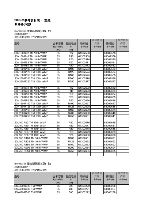
2009年参考价目表 - 塑壳断路器(S型) Isomax S3 塑壳断路器(S型) - 抽出式移动部分
Isomax S5 塑壳断路器(S型) - 抽出式移动部分
Isomax S3 塑壳断路器(S型) - 抽出式移动部分
2009年参考价目表 - 塑壳断路器(S型)
2009年参考价目表 - 塑壳断路器(S型)
S6 塑壳断路器(S型) - 抽出式抽出部份
S7 塑壳断路器(S型) - 抽出式
2009年参考价目表 - 塑壳断路器(S型)
S3X 塑壳断路器(S型) - 插入式抽出部份
S4X 塑壳断路器(S型) - 插入式抽出部份
S3X 塑壳断路器(S型) - 抽出式抽出部份
S4X 塑壳断路器(S型) - 抽出式抽出部份
S6X 塑壳断路器(S型) - 抽出式抽出部份
2009年参考价目表 - 塑壳断路器(S型)
S2X 塑壳断路器(S型) - 插入式抽出部份
2009年参考价目表 - 塑壳断路器(S型)。
2009一汽大众迈腾警车维修手册
售后服务3售后服务技术信息修理手册Magotan 2008迈腾警车维修手册版本: 12.2008售后服务3Printed in China维修手册修理组Magotan 2008工长和机工必需掌握所有技术信息。
因为认真和持久地维护并遵循注意事项是保证车辆行驶和安全的基本条件。
此外在维修时也要遵循维修安全的基本原则。
迈腾警车维修手册版本: 12.2008修理组68、91、94、96、97警车装备Magotan 2008迈腾警车维修手册 12.2008目录iii3目录68、91、94、96、97-警车装备 . . . . . . . . . . . . . . . . . . . . . . . . . . . . . . . . . . . . . . . . . . . . . . . . . .1中央控制系统 . . . . . . . . . . . . . . . . . . . . . . . . . . . . . . . . . . . . . . . . . . . . . . . . . . . . . . . . . . 1.1中央控制系统连接示意图 . . . . . . . . . . . . . . . . . . . . . . . . . . . . . . . . . . . . . . . . . . . . . . . . . 1.2中控主机 -J608-的拆卸和安装 . . . . . . . . . . . . . . . . . . . . . . . . . . . . . . . . . . . . . . . . . . . . . 1.3顶部警灯控制器 -J326-和前后频闪灯控制器 -J483-的拆卸和安装 . . . . . . . . . . . . . . . . . . 1.4音频控制器 -E507-的拆卸和安装 . . . . . . . . . . . . . . . . . . . . . . . . . . . . . . . . . . . . . . . . . . . 1.5车载电台 -J753-的拆卸和安装 . . . . . . . . . . . . . . . . . . . . . . . . . . . . . . . . . . . . . . . . . . . . . 1.6拆卸和我安装鱼鳍天线 . . . . . . . . . . . . . . . . . . . . . . . . . . . . . . . . . . . . . . . . . . . . . . . . . . . 2电器 . . . . . . . . . . . . . . . . . . . . . . . . . . . . . . . . . . . . . . . . . . . . . . . . . . . . . . . . . . . . . . . . 2.1前逆变器 -U13-的拆卸和安装 . . . . . . . . . . . . . . . . . . . . . . . . . . . . . . . . . . . . . . . . . . . . . .2.2后逆变器 -U27-的拆卸和安装 .. . . . . . . . . . . . . . . . . . . . . . . . . . . . . . . . . . . . . . . . . . . . . 3车内设备 . . . . . . . . . . . . . . . . . . . . . . . . . . . . . . . . . . . . . . . . . . . . . . . . . . . . . . . . . . . . .3.1脚铐链的拆卸和安装 . . . . . . . . . . . . . . . . . . . . . . . . . . . . . . . . . . . . . . . . . . . . . . . . . . . . 3.2后座椅手铐链的拆卸和安装 . . . . . . . . . . . . . . . . . . . . . . . . . . . . . . . . . . . . . . . . . . . . . . . 4拆卸和安装顶部警灯. . . . . . . . . . . . . . . . . . . . . . . . . . . . . . . . . . . . . . . . . . . . . . . . . . . . 5拆卸和安装电源总开关 . . . . . . . . . . . . . . . . . . . . . . . . . . . . . . . . . . . . . . . . . . . . . . . . . . . 6拆卸和安装前/后频闪灯 . . . . . . . . . . . . . . . . . . . . . . . . . . . . . . . . . . . . . . . . . . . . . . . . . 6.1拆卸和安装前频闪灯 . . . . . . . . . . . . . . . . . . . . . . . . . . . . . . . . . . . . . . . . . . . . . . . . . . . . 6.2拆卸和安装后频闪灯 . . . . . . . . . . . . . . . . . . . . . . . . . . . . . . . . . . . . . . . . . . . . . . . . . . . .1 1 1 1234 4 4 45 5 56 678 8 8Magotan 2008迈腾警车维修手册 12.2008目录3ivMagotan 2008迈腾警车维修手册 12.20081 中央控制系统131中央控制系统1.1中央控制系统连接示意图1-车载电台 -J753-2-天线3-电源控制器 -J644-4-扬声器5-后逆变器 -U27-6-前逆变器 -U13-7-音频控制器 -E507-8-中控主机 -J608-9-频闪灯控制器 -J483-10-前频闪灯11-后频闪灯12-顶部警灯 -L5-13-顶部警灯控制器 -J326-14-显示器 -L145-15-电话话筒1.2中控主机 -J608-的拆卸和安装拆卸-关闭点火开关及所有用电器,拔出点火钥匙。
2009年美国霍纳德摩托公司有限公司-版权所有-钢铁驴支架支架装置套件P N 08L56-MEG-1
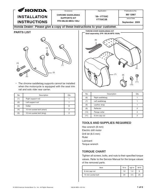
WASHER (Save)
BOLT (Save)
(2) (5)
• The chrome saddlebag supports cannot be installed when the motorcycle is equipped with the seat trim rail and solo rider rear carrier.
No.
Description
LEFT BACKREST MOUNTING BRACKET
10 mm SOCKET BOLT (short)
COLLAR (long) Included in the Backrest mounting bracket.
10 mm SOCKET BOLT (long)
COLLAR (short) Included in the Backrest mounting bracket.
LEFT REAR FENDER RAIL
To Install with the Rear Fender Rail and Backrest Stay
BACKREST STAY REAR TURN SIGNAL AND BRACKET ASSEMBLY
LEFT SUPPORT ROD
10 mm SOCKET BOLT (short)
LEFT SUPPORT ROD
LEFT BACKREST STAY REAR TURN SIGNAL AND BRACKET ASSEMBLY
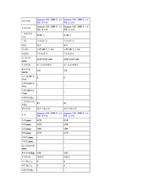
尚酷2009款
●
-
全景天窗:
●
-
运动外观套件:
-
-
铝合金轮毂:
●
●
电动吸合门:
-
-
内部配置
Scirocco尚酷2009款1.4 TSI豪华版
Scirocco尚酷2009款1.4 TSI运动版
真皮方向盘:
●
●
方向盘上下调节:
●
●
方向盘前后调节:
●
●
方向盘电动调节:
-
-
多功能方向盘:
●
●
方向盘换挡:
●
●
定速巡航:
后排头部气囊(气帘):
●
●
膝部气囊:
-
-
胎压监测装置:
●
●
零胎压继续行驶:
-
-
安全带未系提示:
-
-
发动机电子防盗:
●
●
车内中控锁:
●
●
遥控钥匙:
●
●
无钥匙启动系统:
-
-
操控配置
Scirocco尚酷2009款1.4 TSI豪华版
Scirocco尚酷2009款1.4 TSI运动版
ABS防抱死:
●
●
制动力分配(EBD/CBC等):
发动机型号:
EA111
EA111
汽缸容积(cc):
1390
1390
排量(L):
1.4
1.4
工作方式:
机械+涡轮增压
机械+涡轮增压
汽缸排列形式:
L
L
汽缸数(个):
4
4
每缸气门数(个):
4
4
《中国市场手机调查》

整理课件
一、中国手机市场特点
2009国内市场销量
❖ 中国的手机企业在近年展现了强劲的发展势头。根据有关部 门发布的数据,2009年今年第一季度,国内手机销售总量 (不计黑手机和水货手机)达到了3564万部,第二季度,国内 手机市场总销量达到3307万部(未计入“黑手机”和水货手 机), 2009年第三季度我国国内手机销量已达3907万部,第四 季度国内手机销售总量达4877.5万部(不计黑手机和水货手 机)
整理课件
中国市场手机调查
——陈佳月
整理课件
目录
❖ 一. 中国手机市场特点 ❖ 1.1 国内市场销量及品牌排行 ❖ 1.2 核心技术缺乏 ❖ 1.3 重视手机外观设计 ❖ 1.4 产品更新速度加快 ❖ 1.5 营销竞争越来越激烈 ❖ 二. 消费者心理动机分析 ❖ 三. 手机市场用户关注分析 ❖ 3.1 手机品牌关注分析 ❖ 3.2 手机外观关注分析
整理课件
❖ 核心技术缺乏
价格战的背后是技术缺乏 智能机的异军突起
整理课件
重视手机外观设计
整理课件
产品更新速度加快
❖ 诺基亚老大地位的保障 ❖ 摩托罗拉的下滑
整理课件
❖ 营销竞争越来越激烈 ❖ 消费者心理动机分析
手机不只是单纯的科技装置,手机是一种社会化的商品, 其使用往往反映出 社会范畴或社会经济群体的差异,受社会经济基础、社会 结构的制约,也塑造新的行为模式。手机以青少年与年轻 群体为主要用户,反映出年龄在消费中的差异;富有阶层 的炫耀型消费与收入较低阶层持有率较低的现象反应阶级 或收入的差异;市场上针对女性设计、制造、营销,以及
MD7LWA LonWorks (ultra-slim, FTT-10A) 产品说明书

MODEL: MD7LWA Lightning Surge Protectors forElectronics Equipment M-RESTERLIGHTNING SURGE PROTECTOR FORLonWorksMODEL: MD7LWA–[1][2]Specify a code from below for each of [1] and [2].(e.g. MD7LWA-FF/Q)•Specify the specification for option code /Q(e.g. /C01)[1]SHIELD TERMINAL (to earth)FF: FloatingFG: Grounding[2]OPTIONSblank: none/Q: Options other than the above (specify the specification)/C01: Silicone coating/C02: Polyurethane coatingThis unit is not applicable to LonWorks Link Power network.Degree of protection: IP20Connection: Euro terminal block (torque 0.3 N·m)Applicable wire size: 0.2 – 2.5 mm2, stripped length 8 mmGrounding: DIN RailHousing material: Flame-resistant resin (black)Operating humidity: 30 to 90 %RH (non-condensing)Mounting: DIN Rail (TH35-7.5, 1-mm-thick)Oxide film on the surface of an aluminium DIN rail maylower the electric conductivity between this module and theground. Use a steel or copper rail.Weight: 70 g (2.5 oz)LINE TOLINELINE TOEARTHSHLD TOEARTHMax. continuousoperating voltage (Uc)±1.5V±100V±160V*1Voltage protection level(Up) @4kV (1.2 / 50 µs)±30V±370V±800V*1Leakage current @Uc≤ 5µA≤ 20µA≤ 5µA*1Response time≤ 4 nsec.≤ 20 nsec.≤ 20 nsec.*1Approx. capacitance@10 kHz100 pF100 pF 5 pF*1Max. discharge current(Imax)20kA (8 / 20 µs)1.0kA (10 / 350 µs)Nominal current (I N)100mAInternal series resistance≤ 3.3Ω including returnInsertion loss-0.5 dB max. @DC...5 MHz, Z0 = 100ΩSurge protection IEC 61643-21 Categories C1, C2, D1*1. V alues for the oating type (FF). Shortcircuited for the ground-ing type (FG).EMC DirectiveEMI EN 61000-6-4EMS EN 61000-6-2RoHS Directive056 222 38 18SEN TRONICAG8–M3 EURO*1. Be sure to use twisted-pair cables.*2. Choose the M-RESTER – FG when the shield wire is to be grounded.*3. When the twisted-pair cable is with a shield, connect it to the surge protector’s terminal 8, and follow instructions given by the protecteddevice for the terminal 7. When SHLD is not isolated from NET A / B, DO NOT connect the terminal 7 to SHLD.*4. Oxide film on the surface of an aluminium rail may lower the electric conductivity between this module and the ground. Use a steel or copper rail.*5. Be sure to ground the DIN rail. Recommended grounding resistance max. 100 ohms.*6. Cross-wire from the DIN rail to the metal housing of the protected device to equalize the ground potential.Ground only the surge protector when the protected device has no grounding terminal.Protected Devices (Nodes)Protected Devices (Nodes)• T he M-RESTER is applicable to networks which consist only of FTT-10A. Not applicable to the ones connected to Link Power network.• The maximum number of nodes connectable to the network segment is reduced by one when one unit of M-RESTER is added.• When the distance between nodes are relatively long (e.g. grouped and separated by cabinets),install the M-RESTER by each group of devices. Insert the M-RESTER at the surge side of the network.• For detailed information on the network, refer to L ON W ORKS FTT-10A Free Topology Transceiver User’s Guide provided by Echelon.。
- 1、下载文档前请自行甄别文档内容的完整性,平台不提供额外的编辑、内容补充、找答案等附加服务。
- 2、"仅部分预览"的文档,不可在线预览部分如存在完整性等问题,可反馈申请退款(可完整预览的文档不适用该条件!)。
- 3、如文档侵犯您的权益,请联系客服反馈,我们会尽快为您处理(人工客服工作时间:9:00-18:30)。
[] 王利 , 2 陆匠心. 宝钢高等级汽车板 的生产技术及发展 [ ]/ C /
2 0 年全 国炼钢 、 04 轧钢生产技术会议论文集. 无锡 : 中国金
属学会 ,04:7— 3 20 5 6 .
度约 1 0 P , 0M a热轧组织为铁素体加珠光体 , 5 而 热 冲压后 为马 氏体组 织 J 目前 , 。 国外 已经开
同比增长 38 20 年中国粗钢产量 5 68亿 t同比增长 1.% , .%。 0 9 .7 , 35 占全球 总产量的 4 .% , 占比 66 所 重比20 年提高 8 9 08 . 个百分点。
— —
摘 自“中国联合钢铁 网”
() 4 其他钢种 其他钢种如高强度 的 D 10 、 RP 00 超 P00 T I10 、 细晶粒高强钢等, 国内的一些企业和研究院所也 有相应 的研究 。
4 结语
中国汽车工业迅猛发展, 已成为国民经济的 支柱 产业 , 车型 的推 出已经 基本 和 发达 国家 同 新
步 , 就 要求 汽 车 材 料 的研 发 必 须 与世 界 同步 。 这
始大 批量生产 含 硼热 冲压 成 型钢 , 我 国仅 宝钢 而 等 厂 家 引进 了两 条 生 产线 , 于工 业 摸索 阶段 。 处 相关 工业应 用基础研究 的报道很 少 。
[ ] 田志强, 3 唐荻 , 江海 涛, 汽车用双相 钢研究 与生产 现状 等. [] 机械工程材料 ,09 3 ( ) 1 5 J. 20 ,3 4 : - . [ ] 陆匠心 , 4 王利. 高强度 汽车钢板 的生产与使用 [ ] 汽车工 J. 艺与材料 , 0 ( ) 1 6 2 4 2 :— . 0 [ ] 江海涛 , , 5 唐荻 米振莉. 车用先 进高强度钢的开发及应用 汽 进展[ ] 钢铁研究学报 , 0 ( ) l 5 J. 2 78 : 一 . 0 [ ] 张志勤 , 6 何立波 , 高真凤. 蒂森克虏伯钢铁公 司汽车板生产 现状[ ] 鞍钢技术 ,O5 5 : — . J. 2O ( )6 8 [ ] 王利 , 雄飞 , 7 杨 陆匠心. 车轻量 化用 高强度 钢板 的发展 汽 [] 钢铁 , 0 ,1 9 : — . J. 2 64 ( ) 1 8 0 [ ] 马呜图, . .h. 8 M F Si 先进的高强度钢及其在汽车工业 中的应 用[ ] 钢铁 , 0 , ( ) 6 — 2 J. 2 43 7 : 7 . 0 9 8
( 编辑
许营)
今后汽车用钢 的发展方向是开发新型先进高强
扣 和 扣 和 和 + 扣 扣 和 和 和 和 和 扣 扣 和 ■ + 扣 扣 扣 叶 叶
收稿 日期 :0 9~1 9 20 0—1
扣 扣 扣 和 和 扣 扣
20 0 9年全球粗钢产量 同比下降 8 %
国际钢铁协会( o d e1在布鲁塞尔当地时间 1 2 公布的统计报告表明, 0 年全球 6 个 wrse lt ) 月 21 3 2 9 0 6 主要产钢国和地区粗钢产量全年累计为 1.9亿 t同比下降 8 1 19 , .%。20 年全球所有国家粗钢产量累 09
近年来 , 国外采用热冲压成型工艺对含硼钢
进行 了研 究 , 并获 得 了超 高强 零件 , 强度 可达 1 0 P 0M a以上 J 5 。该工艺首先将轧后的含硼钢 板在加热炉中加热至 80~ 5 5 90℃ , 保温数分钟 ,
apctn[ ]/ ae M A r .o I.Cn nA— plaos C /Bkr .Po fn of d ii c t .O
计 l. 22亿 t同 比下降 8 。 , %
该统计数据还显示 , 0 年欧盟 2 2 9 0 7国粗钢产量为 13 .9亿 t同比下降 2. % ; , 97 独联体粗钢产量为
976万 t同比下降 1.% ; 3 , 47 北美粗钢产量为 8 2 5万 t同比下降 3 .%; 2 , 39 亚洲粗钢产量为 676亿 t .5 ,
用钢 达到世 界先进水平 。 参考 文献
[ ] H r t CD FktJ . poui s n aeg f i 1 o a , ee R O prn e ad h l e o n vh e t t c ln s r - i
cesduaeo dacd hg t nt t l i uo bl r8e sg fa v e ibs eg se s na t n r h e moi e
< 鞍钢技术) 00年第 1期 21 唐荻等: 国内冷 轧汽车 用钢的研发历史、 现状及发展趋势
总 第 3 1期 6
目前 , 国内外对 Q P & 工艺的研究还处于起步 阶段 , 相关的理论研究仅为初步探索阶段。不过 , Q P钢具有优异 的强度和塑性综合性能, & 作为汽 车结构用钢, 可大大减轻车体质量, 增强车体抵抗 撞击 的能力 , 提高汽车运行的安全性, 具有很好的
vn e g t nt Sel fr A tm t e A pi tn a ed Hi Sr g t s o uo o v p l i s. h e h e i a c o
US AIT le o 2 04: A: S God n C .,0 1—7 .
待钢板完全奥氏体化后 , 利用 自动化装置在数秒 钟内将其送入一个带有冷却系统 的冲压模具 中,
发 展前景 。 ( )热 冲压成型 钢 3
钢, 在进一步提高强度 、 降低车重的同时, 要综合 考虑安全、 成的开发中。我国钢铁企业应及时掌 握国内外先进高强度汽车钢板的发展动向, 时 适 地进行产品开发及应用技术 的研究, 使我 国汽车
