RF-GP2033TP-03E中文资料
云浮检验检疫局视频会议系统设备清单

C—20节
电池箱尺寸:450×950×1230(W×D×H)mm总重量:约100kg/2个
台
2
4
电池连接电缆
套
1
5
监控软件
winpower2003管理监控软件
套
1
二、视频会议系统
6
会议主机
DCN-CCUB
BOSCH
台
1
7
会议代表单元
DCN-CONFF
BOSCH
台
5
4个代表位
8
会议主席单元
DCN-CONCM
BOSCH
台
1
1个主席位
9
连接电缆
LBB 4116/25
BOSCH
卷
2
10
显示单元
飞利浦47PFL7422
台
1
液晶电视屏幕尺寸:47英寸屏幕比例:16:9幕亮度:500cd/m2
11
大屏幕管理软件
定做
Abebe
块
1
12
DVI线缆
国产
国产
套
1
13
主音音箱
JBL confrloc 28
JBL/美国
只
2
额定功率50S
BEHRINGER
台
1
带功放、均衡功能
15
手持无线麦
SHURE 24/58
美国SHURE
套
2
16
32U
标准专业机箱
金盾
套
1
17
其他辅助材料设备
吊架、电缆线、咪线
国产
批
1
三、网络设备需求清单
18
防火墙
NGFWARES-VPN(S)
T3e中文操作手册

操作
目录
注意事项 ················································ 4 安全标签 ················································ 5 机器组件 ················································ 6 控制面板符号 ········································· 6 安装机器 ················································ 7
操作
- 从卡车或拖车装卸机器时,请使用建议的 装卸坪。
- 使用绳索将机器固定在卡车或拖车上。 - 将刷头下降至降低位置。
安全标签
安全标签会依照指示的位置标在机器上。如果标签遗落、损毁或难以辨识,请更换标签。
警告标签——位于污水箱盖上。
警告
爆炸、火灾或触电危险。避免人员受 伤。 ●请勿使用或拾取易燃材料。 ●请勿在易燃液体、蒸汽或易燃粉尘
以下针对本手册中使用的安全警示符号与「为安 全起见」标题进行说明:
警告:用于警告会导致严重人员伤害或死亡的 风险或不安全的操作。
为安全起见:指出使用机器时所必须遵守的事项 以保障安全。
柿饼 M3 模块硬件手册说明书

柿饼M3模块硬件手册1.概要信息1.1产品简介柿饼M3是上海睿赛德电子科技有限公司基于柿饼UI开发的一款显示屏板卡,用于提供IoT、智能家居、消费电子等领域的屏幕开发解决方案。
作为柿饼派的升级版本,柿饼M3尺寸小巧,功能强悍,支持丰富的外设通讯接口,可外接传感器或其他主控单元,支持丰富的网络协议和音视频播放,此外,柿饼M3支持FOTA功能,便于远程维护升级。
1.2基本参数●主控:RT1806高性能32位处理器●内置SDRAM:32MB●板载Flash:16MB●支持RGB666接口,支持常见的480*272,800*480,1024*600分辨率●支持UART、SPI、SDIO、IIC通信接口●支持USB-HOST功能可接移动4G模块或U盘●支持音视频播放●支持硬件JPEG解码●支持丰富的网络协议(MQTT、HTTP、HTTPS、WebSocket、TCP)●搭配柿饼UI,界面开发便捷,控件丰富(支持多种常用控件、可支持自定义控件)支持小程序多APP应用●支持FOTA安全升级机制2.模块典型应用框图图示为模块典型应用框图,详细参考电路见参考原理图资料。
3.规格参数模块相关规格参数如下:主要参数最小值典型值最大值单位工作温度-202570℃储存温度-302580℃工作湿度10%60%90%RH供电电压 4.5 5.0 5.5V供电电流90100120mAI/O支持电压 3.0 3.3 3.6VCodec支持电压 2.5 3.8 3.1VUSB支持电压 3.0 3.3 3.6V通信电平 3.3V 静电防护(默认)2(接触)24(空气)KV推荐回流温度:4.尺寸与引脚定义4.1尺寸大小项目参数外形尺寸27mm(长)*27mm(宽)*3.5mm(高)焊盘中心间距 1.27mm焊盘距板边距离 2.7mm注:详细参数见封装资料。
4.2引脚定义图4.3默认引脚定义PIN引脚Symbol符号说明Remark备注1,2,49-64LCD_D22,LCD_D23,LCD_D2-LCD_D21RGB数据接口默认RGB666,详情见示意图3LCD_CLK LCD屏时钟线4LCD_DE LCD屏片选脚5LCD_HSYNC RGB帧同步信号6LCD_VSYNC RGB场同步信号7,8VCC_5V电源供电4.5V-5.5V9,10GND电源地11SDA IIC数据线12SCL IIC时钟线13SD_DETC SD卡使能接口14SPK_SHDN音频使能接口(低有效)15,16U2_RX,U2_TX UART2串口信号输出、输入该串口为控制台,默认参数为1152008N117PWM1LCD背光调节接口18PE5WiFi初始化引脚不使用WiFi功能时,可做通用IO使用19PE4WiFi复位引脚同上20TP_INT/PE3触摸IC初始化引脚不使用触摸功能时,可做通用IO使用21TP_RST/PE2触摸IC复位引脚同上22,23LCD_D0/U0_RX,LCD_D1/U0_TX LCD的D0,D1引脚该串口为预留串口,默认参数为1152008N124,25SDIO_D2,SDIO_D3SD卡的SDIO数据D2,D3引脚26SDIO_CMD SDIO的命令引脚27SDIO_CLK SDIO的时钟引脚28,29SDIO_D0,SDIO_D1SD卡的SDIO数据D0,D1引脚30SPI_MISO/PA3默认为WiFi的SPI引脚不使用WiFi功能时,可做通用IO或SPI使用31SPI_CLK/PA2同上32SPI_MOSI/PA1同上33SPI_CS0/PA0同上34,35USB_DM,USB_DP USB数据线36RESET CPU复位引脚37TV_OUT38,39TV_IN1,TV_IN040LRADC ADC-Key带ADC功能的按键,6位分辨率41FMINL42FMINR43LINEIN44MICIN45,46HPR,HPL音频右/左声道输出47,48HPCOM_FB,HPCOM免责声明上海睿赛德电子科技有限公司随附提供的文档资料旨在提供给您(本公司的客户)使用,仅限于且只能在本公司销售或提供服务的产品上使用。
TP-Link Deco M3W 用户手册说明书
ContentsAbout This Guide (1)Appearance (2)Set Up Y our Deco Extender (3)Dashboard (5)Update Deco Units (6)Authentication (7)About This GuideThis guide provides a brief introduction to Deco Whole Home Mesh Wi-Fi Extender and the Deco app, as well as regulatory information.Please note that features of Deco Extenders may vary slightly depending on the model and software version you have, and on your location, language and internet service provider. All images, parameters and descriptions documented in this guide are used for demonstration only.ConventionsMore Info• Specific product information can be found on the product page at https://.• A Technical Support Forum is provided for you to discuss our products at https://.• Our T echnical Support contact information can be found at the Help center of the Deco app and the Contact T echnical Support page at https:///support.Speed/Coverage/Device Quantity Disclaimer Maximum wireless transmission rates are the physical rates derived from IEEE Standard 802.11 specifications. Range, coverage, and maximum quantity of connected devices are based on test results under normal usage conditions. Actual wireless data throughput. wireless coverage, and quantity of connected devices are not guaranteed and will vary as a result of 1) environmental factors, including building materials, physical objects, and obstacles, 2) network conditions, including local interference, volume and density of traffic, product location, network complexity, and network overhead, and 3) client limitations, including rated performance, location, connection quality, and client condition.operational temperature:0-40度2Appearance Deco Extender has four LED lights and a Reset button. See the explanation below:Reset Button:Press to reset Deco Extender to factory default settings.3Set Up Y our Deco Extender Follow the steps below to add the Deco Extender to your existing Deco network.Before you start Install the Deco app and set up a Deco network. For instructions, refer to the user manual of your Deco Whole Home Mesh Wi-FiSystem/Unit. 2. Add your Deco Extender On the dashboard, tap + and select DECOS .Identify your Deco model. 3. Find a suitable spot Follow the app instructions to find a suitable spot within the range of your existing Deconetwork.44. Plug in your Deco Extender Plug the Deco Extender into a wall outlet andwait until its Power LED turns solid on. 5. Specify the location Select a location for this Deco Extender. If its location is not listed, you can create a new one by choosing Custom. 6. Finish The Deco app will automatically optimize your Deco network and finish adding the DecoExtender.View connected devices Display all Deco units Check the working status56Update Deco Units TP-Link is dedicated to improving product features and providing a better customer experience. Update Deco units when prompted in the Deco app.Update AvailableUpdating DecoUp-to-dateAuthenticationCOPYRIGHT & TRADEMARKSSpecifications are subject to change without notice. is a registered trademark of TP-Link T echnologies Co., Ltd. Other brands and product names are trademarks or registered trademarks of their respective holders.No part of the specifications may be reproduced in any form or by any means or used to make any derivative such as translation, transformation, or adaptation without permission from TP-Link T echnologies Co., Ltd. Copyright © 2018 TP-Link T echnologies Co., Ltd. All rights reserved.FCC compliance information statementProduct Name: AC1200 Whole Home Mesh Wi-Fi ExtenderModel Number: Deco M3WResponsible Party:TP-Link USA Corporation, d/b/a TP-Link North America, Inc.Address: 145 South State College Blvd. Suite 400, Brea, CA 92821Website: /us/T el: +1 626 333 0234Fax: +1 909 527 6803E-mail:*********************This equipment has been tested and found to comply with the limits for a Class B digital device, pursuant to part 15 of the FCC Rules. These limits are designed to provide reasonable protection against harmful interference in a residential installation. This equipment generates, uses and can radiate radio frequency energy and, if not installed and used in accordance with the instructions, may cause harmful interference to radio communications. However, there is no guarantee that interference will not occur in a particular installation. If this equipment does cause harmful interference to radio or television reception, which can be determined by turning the equipment off and on, the user is encouraged to try to correct the interference by one or more of the following measures:• Reorient or relocate the receiving antenna.• Increase the separation between the equipment and receiver.• Connect the equipment into an outlet on a circuit different from that to which the receiver is connected.• Consult the dealer or an experienced radio/ TV technician for help.This device complies with part 15 of the FCC Rules. Operation is subject to the following two conditions:1. This device may not cause harmful interference.2. This device must accept any interference received, including interference that may cause undesired operation.Any changes or modifications not expressly approved by the party responsible for compliance could void the user’s authority to operate the equipment.Note: The manufacturer is not responsible for any radio or TV interference caused by unauthorized modifications to this equipment. Such modifications could void the user’s authority to operate the equipment.FCC RF Radiation Exposure Statement:This equipment complies with FCC RF radiation exposure limits set forth for an uncontrolled environment. This device and its antenna must not be co-located or operating in conjunction with any other antenna or transmitter.“T o comply with FCC RF exposure compliance requirements, this grant is applicable to only Mobile Configurations. The antennas used for this transmitter must be installed to provide a separation distance of at least 20 cm from all persons and must not be co-located or operating in conjunction with any other antenna or transmitter.”This device is restricted in indoor environment only.We, TP-Link USA Corporation, has determined that the equipment shown as above has been shown to comply with the applicable technical standards, FCC part 15. There is no unauthorized change is made in the equipment and the equipment is properly maintained and operated.Issue Date: 2018-10-24CE Mark WarningThis is a class B product. In a domestic environment, this product may cause radio interference, in which case the user may be required to take adequate measures.OPERATING FREQUENCY (the maximum transmitted power)2400 MHz -2483.5 MHz (20dBm)5150 MHz -5250 MHz (23dBm)5250 MHz -5350 MHz (23dBm)5470 MHz -5725 MHz (30dBm)EU Declaration of ConformityTP-Link hereby declares that the device is in compliance with the essential requirements and other relevant provisions of directives 2014/53/EU, 2009/125/EC and 2011/65/EU.The original EU declaration of conformity may be found at /en/ceRF Exposure InformationThis device meets the EU requirements (2014/53/EU Article 3.1a) on the limitation of exposure of the general public to electromagnetic fields by way of health protection.The device complies with RF specifications when the device used at 20 cm from your body.Restricted to indoor use.Canadian Compliance StatementThis device complies with Industry Canada license-exempt RSSs. Operation is subject to the following two conditions:1. This device may not cause interference, and2. This device must accept any interference, including interference that may cause undesired operation of the device.Le présent appareil est conforme aux CNR d’Industrie Canada applicables aux appareils radio exempts de licence. L’exploitation est autorisée aux deux conditions suivantes :1. l’appareil ne doit pas produire de brouillage;2. l’utilisateur de l’appareil doit accepter tout brouillage radioélectrique subi, meme si le brouillage est susceptible d’en compromettre le fonctionnement.Caution:1. The device for operation in the band 5150–5250 MHz is only for indoor use to reduce the potential for harmful interference to co-channel mobile satellite systems;DFS (Dynamic Frequency Selection) products that operate in the bands 5250- 5350 MHz, 5470-5600MHz, and 5650-5725MHz.Avertissement:1. Le dispositif fonctionnant dans la bande 5150-5250 MHz est réservé uniquement pour une utilisation à l’intérieur afin de réduire les risques de brouillage préjudiciable aux systèmes de satellites mobiles utilisant les mêmes canaux;Les produits utilisant la technique d’atténuation DFS (sélection dynamique des fréquences) sur les bandes 5250- 5350 MHz, 5470-5600MHz et 5650-5725MHz.Radiation Exposure Statement:This equipment complies with IC radiation exposure limits set forth for an uncontrolled environment. This equipment should be installed and operatedwith minimum distance 20cm between the radiator & your body.Déclaration d’exposition aux radiations:Cet équipement est conforme aux limites d’exposition aux rayonnements IC établies pour un environnement non contr lé. Cet équipement doit être installé et utilisé avec un minimum de 20 cm de distance entre la source de rayonnement et votre corps.Industry Canada StatementCAN ICES-3 (B)/NMB-3(B)Korea Warning Statements당해 무선설비는 운용중 전파혼신 가능성이 있음.NCC Notice & BSMI Notice注意!依據 低功率電波輻射性電機管理辦法第十二條 經型式認證合格之低功率射頻電機,非經許可,公司、商號或使用者均不得擅自變更頻率、加大功率或變更原設計之特性或功能。
施耐德装置应用指南

1000 V
1000 V
1000 V
1000 V
3或4
3或4
3或4
3或4
30 kW 55 kW 59 kW 59 kW 75 kW 80 kW 65 kW
40 kW 75 kW 80 kW 80 kW 90 kW 100 kW 65 kW
55 kW 90 kW 100 kW 100 kW 110 kW 110 kW 100 kW
i
选型指南
应用
TeSys 接触器
115 至 2750 A
控制所有类型的电动机,适用于标准和重载应用 控制电阻、电感和电容性电路:加热、照明、功率因数补偿、变压器 常规 - 备用电源
额定工作电流 额定工作电压
Ie max AC-3 (Ue ≤ 440 V)
Ie max AC-1 (θ ≤ 40 °C)
F 型电子式热过载继电器
● 概述、说明 . . . . . . . . . . . . . . . . . . . . . . . . . . . . . . . . . . . . . . . . . . . . . . . . . . . . . . . . . . . . . . . . . . . . . . . . . .2/2 ● 特性 . . . . . . . . . . . . . . . . . . . . . . . . . . . . . . . . . . . . . . . . . . . . . . . . . . . . . . . . . . . . . . . . . . . . . . . . . . . . . . . . . .2/3 ● 型号 . . . . . . . . . . . . . . . . . . . . . . . . . . . . . . . . . . . . . . . . . . . . . . . . . . . . . . . . . . . . . . . . . . . . . . . . . . . . . . . . . .2/6 ● 辅助模块与附件 . . . . . . . . . . . . . . . . . . . . . . . . . . . . . . . . . . . . . . . . . . . . . . . . . . . . . . . . . . . . . . . . . . . . .2/8 ● 尺寸、线路图、设置说明 . . . . . . . . . . . . . . . . . . . . . . . . . . . . . . . . . . . . . . . . . . . . . . . . . . . . . . . . . 2/10
三菱多功能电子测量仪

警报延长 时间
警报发生
最大值更新
上限值
下限值
最小值更新 0A、0V时不输出下限警报。
时间
设备启动时的便利的测试功能
在设备启动时没有电流、电压输入的状态下也应答模拟输出、脉冲输出、警报输出及通讯数据。因此可简易地进行配线及系统监控程 序的确认。
5
功能说明
LCD的功能
1
2
1 LEAD(超前)显示
2 LAG(滞后)显示
●对应DIN 96×96 尺寸 ●3P4W/3P3W 共用 ●输出选购件后装式 ●符合CE标志 ●符合欧州RoHS指令(2002/95/EC)
监控
三菱独有的ASIC给您带来 高精度的测量功能
●监控上/下限值项目达4项之多 ●谐波监控 ●测量导入/导出有功能量
显示
屏幕显示读取容易
●可显示4项项目 ●背景灯自动关闭功能
小数点位置会移动 4
便利于设备监控的上下限监控功能
●最大可上下限监控4点 在装配有ME-4201-NS96选购件的状态下,发生警报时能接点输出。 (因接点输出为1点,所以输出为被设定上下限警报项目的OR输出)
■基于LCD的上下限警报显示 可确认对应于现在值显示及最大值、最小值显示的警报发生状态。
<现在值显示画面的警报显示例>
6
■ 外形、安装、连接
23
■ 型号一览
26
■ 安全注意事项
28
概要及特长
ModBus通讯系统对应(ME96NSR-MB,选购件ME-0052-NS96)
中央监视装置
RS485/RS232 转换器
RS232
RS485(ModBus)
●最适合于PC监控的ModBus通讯系统 ●通过安装选购件ME-0052-NS96,可监控远程接点输入信号及控制接点输出信号的
欧姆龙产品更新说明说明书

更新于2013年4月BEST第16版光电传感器PA-125,E3F3-R61/R81传感距离不是2m,应改为3m。
定时器PE-40,H3CR-F8的CAD文件中应该是与P2CF-08组合。
PE-44,与P3G-08配合使用的适配器型号是Y29F-30,应是Y92F-30。
PE-48,H3CR-HRL嵌入式安装的底座是P3G-08,应是P3GA-11。
PE-106,H3CA-8H、H3CA-8H-306有1c限时接点,应是1c限时接点、1c瞬时接点。
开关电源PG-71,本体表格中容量应该是300W和600W,不是30W和60W。
BEST第17版液位设备P-58,动作说明中应是水面升到E1以上时(U1的LED灯亮)。
P-72,LL1和BL1应该是高架水槽缺水。
P-81,E2下限用改为中间用,E1下限用改为上限用P-93,内部连接图中:61F-HSL的表面连接用底座应是8PFA。
P-718,附表1、2中的固有电阻改成电阻率,附表1A中的电导改成电导率。
微动开关P-149,摆杆型、小型线型摆杆型的OP小,OP中,OP大,应该是OF小,OF中,OF大。
P-190,1VAP2-6应是1VAP2-2,1VAP2-2应是1VAP2-6。
P-193,XAA-1的动作特性图中回复力应是动作力,预行程应是回复力。
限位开关P-252,命名规格2中,CL-2、CL-2N是“可调式滚珠摆杆型”错误,应该是“可调式棒式摆杆型”。
P-253,WLI/O连接器型⑤配线规格中的 -M1JB不是“2芯,DC规格、NO配线、连接器查缴No.3、2”,应改为“NC配线”。
P-254,WLD3应是顶部球式柱塞型。
P-255,第二张表格中驱动杆种类前两个“可调式滚珠摆杆”错误,应该是“可调式棒式摆杆”。
P-268,导线规格表格中标准应为5m。
P-281, WL-3A200的长度应该是417.5mm,不是412.5mmP-295,D4A-D00对应的驱动杆的种类不是“可调式滚珠·摆杆型”,应该改成“可调式棒式·摆杆型”。
公司(普飞诺)新推IC及替换型号

二:开关式降压IC可以应用于:蓄电池供电玩具,工业控制器,仪器仪表,医疗设备,安防,电动车控 制器,LED照明灯,家用电器控制板,办公设备等。
三:通信IC可以应用于:工业控制板,电源检测系统,安防设备,门禁系统,楼层烟雾报警系统,电 脑,打印机等。
替换型号 78M05 78M06 78M08 78M09 78M12
公司新推IC及替换型号
一:线性稳压器 序号 型号 1: P78M05 2: P78M06 3: P78M08 4: P78M09 5: P78M12 特点:应用简单,转换效率低,成本低 规格 TO252封装,稳压输出固定+5V TO252封装,稳压输出固定+6V TO252封装,稳压输出固定+8V TO252封装,稳压输出固定+9V TO252封装,稳压输出固定+12V
二:开关式降压IC 序号 型号 规格 1: P2575s-3.3 SOT263封装,固定输出+3.3V 2: P2575T-3.3 TO220封装,固定输出+3.3V 3: P2575S-5.0 SOT263封装,固定输出+5V 4: P2575T-5.0 TO220封装,固定输出+5V 5: P2575S-12 SOT263封装,固定输出+12V 6: P2575T-12 TO220封装,固定输出+12V 7: P2575S-ADJ SOT263封装,输出可调 8: P2575T-ADJ TO220封装,输出可调 9: P2576S-3.3 SOT263封装,固定输出+3.3V 10: P2576T-3.3 TO220封装,固定输出+3.3V 11: P2576S-5.0 SOT263封装,固定输出+5V 12: P2576T-5.O TO220封装,固定输出+5V 13: P2576S-12 SOT263封装,固定输出+12V 14: P2576T-12 TO220封装,固定输出+12V 15: P2576S-ADJ SOT263封装,输出可调 16: P2576T-ADJ TO220封装,输出可调 17: P2596S-3.3 SOT263封装,固定输出+3.3V 18: P2596T-3.3 TO220封装,固定输出+3.3V 19: P2596S-5.0 SOT263封装,固定输出+5V 20: P2596T-5.0 TO220封装,固定输出+5V 21: P2596S-12 SOT263封装,固定输出+12V 22: P2596T-12 TO220封装,固定输出+12V 23: P2596T-ADJ TO220封装,输出可调 24: P2596S-ADJ SOT263封装,输出可调 特点:开关式降压IC,转换效率高,2575输出1A,2576/2596系列最大可输出3A,如2575/2576尾缀带有 HV输入可高达DC60V。默认输入40V。2596与2576两点不同1:开关频率2596为150K,2576为52K。2:259 最大输入为40V。 三:通信IC 序号 型号 1: PFN485CSA 2: PFN485ESA 3: PFN232CSE 4: PFN232ESE
断路器型号大全讲解

低压断路器从它的结构、用途和所具备的功能分为万能式断路器和塑料外壳式断路器两大类,目前我国万能式断路器主要生产有DWI5、DWI6、DWI7(ME) 、DW45等系列,塑壳断路器主要生产有DZ20、CMI、TM30等系列。
断路器都是由本体和附件组成。
举例:HUM18-63C32/1HU-----企业代号(环宇)M18---产品型号63-----壳架等级C------使用类别:照明电路(或者一般电路)32-----额定电流)极1-------1P(1.断路器 DW17-400/3:DW-万能自动空气断路器;17-设计代号;“-400”-额定电流(A);“/3”-3极。
(1)由线路的计算电流来决定断路器的额定电流;(大概有99%的设计者做到了这一条)。
(2)断路器的短路整定电流应躲过线路的正常工作启动电流。
(大概有30%的设计者注意到了这一条)。
(3)按线路的最大短路电流来校验低压断路器的分断能力;(大概有10%的设计者注意到了这一条)。
(4)按照线路的最小短路电流来校验断路器动作的灵敏性,即线路最小短路电流应不小于断路器短路整定电流的1.3倍;(大概有5%的设计者注意到了这一条)。
(5)按照线路上的短路冲击电流(即短路全电流最大瞬时值)来校验断路器的额定短路接通能力(最大电流预期峰值),即后者应大于前者。
高压断路器型号,断路器型号大全,断路器型号一览表我国断路器型号根据国家技术标准的规定,一般由文字符号和数字按以下方式组成。
其代表意义为:ABC-DE/F-GA—产品名称,用下列字母表示:S—少油断路器D—多油断路器; K—空气断路器; L—六氟; Q—产气断路器; Z—真空断路器化硫断路器;C —磁吹断路器。
B—使用环境:; N—户内—户外。
W C—设计系列顺序号:以数字……表示。
31、2、—额定电压,DKV。
—其它补充工作特性标志:E 带有电碰操动机构F —改进型G —分相操作DF—额定电流,。
E3G欧姆龙光电传感器

Ẕ
⌟ 䎱 行
20 Ẕ⌟⠽ԧ˖ⱑ㒌 Ẕ⌟䎱行˖1m
15
ব
࣪
⥛嗻 10
ˁ
嗼5
1.5
0
-5
1
1m
Ϟϟᮍ
-10
ؒ᭰㾦ᑺ
0.5
0.5m
+©
-15
-©
Ẕ⌟⠽ԧ
-20
0
100 200 300 400 500 600
-40 -30 -20 -10 0 10 20 30 40
Ẕ⌟⠽ԧⱘϔ䖍䭓(mm)
ؒ᭰㾦ᑺ˄©e˅
⬉ܝӴᛳ఼
Ӵᛳ఼ᣛफ
放大器内置光电开关 (长距离)
E3G
ܝ㑸ᓣ
长距离光电传感器实现回归反射
ᬒ఼ߚ行ൟ 型10m距离设定型2m
ᬒ఼ݙ㕂ൟ ■小型机可检测10m长距离。若将传统的对射型 换成回归反射型则可省布线、省空间。
⬉⑤ݙ㕂ൟ ■距离设定型带有示教式功能。 ■带有稳定状态一目了然的稳定显示灯。
光源 (发光波长) 红色发光二极管 (700nm)
红外光二极管 (860nm)
投光光点直径
———
φ70mm以下 (检出距离1m时)
电源电压
DC10~30V [包括脉动(p-p)10%]
DC12~240V±10% 脉动(p-p)10%以下 AC24~240V±10% 50/ 60Hz
DC10~30V [包括脉动(p-p)10%]
⫼䗨ߚ㉏ ■输出可选择晶体管输出(NPN/PNP转换) 或继电器输出。
ೈ䆒 ■按用途有导线/接插件/端子台连接方式。
ҟ㒡
详情请参阅225页的 「请正确使用」。
相关信息 技术指南 (技术篇) .............1290
移动电源路由器支持网卡型号
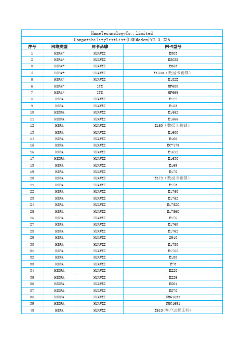
HSPA+
HUAWEI
E182E
6
HSPA+
ZTE
MF680
7
HSPA+
ZTE
MF669
8
HSPA
HUAWEI
E122
9
HSPA
HUAWEI
E153
10
HSDPA
HUAWEI
E1552
11
HSDPA
HUAWEI
E156G
12
HSPA
HUAWEI
E160(数据卡被锁)
13
HSPA
HUAWEI
E160G
ZTE
AC2746
208
EV-DO
ZTE
AC2766
209
EV-DO
ZTE
AC2787
210
EV-DO
ZTE
AC560
211
EV-DO
ZTE
AC560(增强型)
212
EV-DO
ZTE
AC580
213
EV-DO
ZTE
AC581
214
EV-DO
ZTE
AC582
215
EV-DO
ZTE
AC583
216
EV-DO
HSPA
GI0322
HWV42
158
HSPA
VODAFONE
K3760
159
HSPA
orange
GI0225
160
HSPA
at&t
AC885
161
HSPA
at&t
USB 305
162
HSPA
ERG1FGS301E中文资料(PANASONIC)中文数据手册「EasyDatasheet - 矽搜」

Type L
ERG(X)12S 6.35
ERG(X)1S 9.00
ERG(X)1F
ERG(X)2S ERG(X)2F
12.00
ERG(X)3S ERG(X)3F
15.00
ERG(X)5S ERG(X)5F
24.00
外形尺寸(mm)
φD
k
2.3
30.0
2.8
30.0
4.0
30.0
φd
0.65 0.65 0.80 0.80
120 –55 °C
100
80
60 Rated Load (%)
40
20
0 –60 –40 –20 0
70 °C
ERG(X)12S
ERG(X)1S, 1F ERG(X)2S, 2F ERG(X)3S, 3F
ERG(X)5S, 5F
130 °C
235 °C
20 40 60 80 100 120 140 160 180 200 220 240
½Z type isnon standard resistance values.
Code Type Res.Tol. Res. Value Range Code Type Res.Tol. Res. Value Range
±2 % 0.1 to 0.91 12S
±5 % 0.1 to 0.18 Z
The first two digitsare significant figures of resistance and the third one denotes number of zerosfollowing. Decimal point isexpressed by (Ex.) 1R0 : 1.0
SENTRON 三极塑胶保护电路断屉 3VA1 IEC 型号说明书
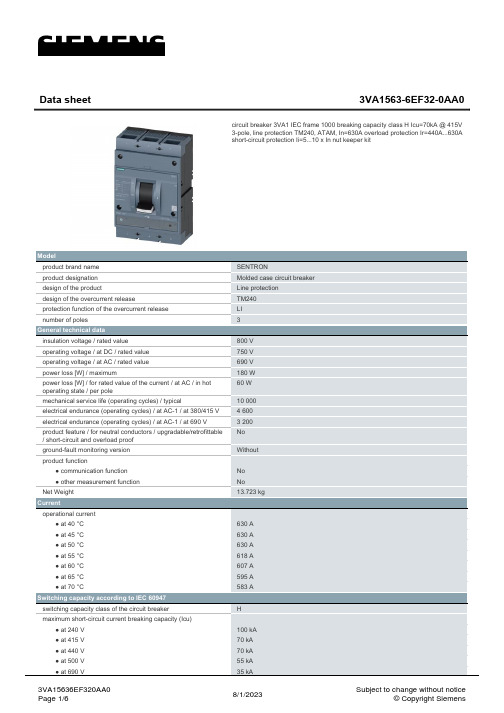
Model product brand name product designation design of the product design of the overcurrent release protection function of the overcurrent release number of poles
General technical data insulation voltage / rated value operating voltage / at DC / rated value operating voltage / at AC / rated value power loss [W] / maximum power loss [W] / for rated value of the current / at AC / in hot operating state / per pole mechanical service life (operating cycles) / typical electrical endurance (operating cycles) / at AC-1 / at 380/415 V electrical endurance (operating cycles) / at AC-1 / at 690 V product feature / for neutral conductors / upgradable/retrofittable / short-circuit and overload proof ground-fault monitoring version product function ● communication function ● other measurement function Net Weight
3M电工产品目录说明书
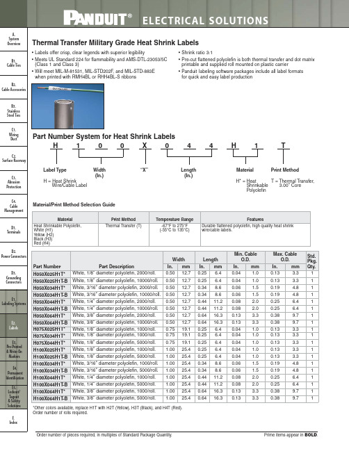
0.04 1.0
0.06 1.5
0.06 1.5
0.08 2.0
0.08 2.0
0.13 3.3
0.13 3.3
0.04 1.0 0.04 1.0
0.04 1.0
0.04 1.0
0.04 1.0
0.06 1.5
0.06 1.5
0.08 2.0
0.08 2.0
Width In. mm 0.50 12.7 0.50 12.7 0.50 12.7 0.50 12.7 0.50 12.7 0.50 12.7 0.50 12.7 0.50 12.7 0.75 19.1 0.75 19.1 0.75 19.1 1.00 25.4 1.00 25.4 1.00 25.4 1.00 25.4 1.00 25.4 1.00 25.4 1.00 25.4 1.00 25.4
*Other colors available, replace H1T with H2T (Yellow), H3T (Black), and H4T (Red). Order number of rolls required.
Length In. mm 0.84 21.3 1.65 41.9 0.25 6.4 0.34 8.6 0.44 11.2 0.25 6.4 0.25 6.4 0.34 8.6 0.34 8.6 0.44 11.2 0.44 11.2 0.64 16.3 0.64 16.3 0.84 21.3 0.84 21.3 1.65 41.9
Min. Cable O.D.
In.
mm
0.170 4.3
C4. Cable Management
Material/Print Method Selection Guide
康佳彩电进入总线大全
TDA9808(中放) P3460T,P3409T,P2902T,P2903T,P3618T,P2906T,P2908T
C型机芯 P83C266
KONKA266(掩模) TDA8843
TDA8839 A2971C,A2980C,P2982C,P2990C,P2986C,P3486C,T3472C,T3877C,T2966C,T2969C,T3466C,T3477C 遥控器下面隐藏有工厂进入键和退出键。
C型机芯 CXP1105S TDA8841
维修方式的退出:
按遥控器上的“AV/TV”键。
三菱机芯 M37220M3-010
M52340 T2136F,T2131F,T2132F,T2133F、T2134F,T2135F
按压遥控器上菜单键“MENU”,同时按压遥控器上的数字键6、4、8、3,屏幕显示FACTORY TIME:1或其他数字,进入工厂调试状态。
E型机 CKP1011S(不能代换)/CKP1011S1(可代换CKP1011S) TB1240N(TB1238N) A2176E,P2190E1,A2188E,T2166E1,A1488E1,A1486E1,T2180E,T2163E,F2109E,F2569E,T2580E,P2590E,P2592E,T2969E,T2566E1/E5,T2980E,P2990E,T3466E,T2563E,T2525,P2929 遥控型号KK-Y169,KK-Y183。按遥控菜单键,再按“呼号”键5次,显示“FAC ON”进入。按数字键分别进入各项。再次按“呼号”键显示“FAC OFF”退出。
超级芯片VCT3803A 中放TDA4472 P2571S,P2571SN,P2960S,P2971S,P2971SN,P2975SN,P3476S 同上。
G3M系列单片包晶体管驱动模块说明书
1,2,3and 5A single in-line package SSRD Thin design for high-density PCB applications.D DC input-AC output for up to a 5-A load.D Two foot prints offer greater flexibility.DApproved by UL and CSA.Ordering InformationT o order:Select the part number and add the desired input voltage rating,(e.g.,G3M-202P-US DC5)Isolation Input terminal pitch Zero cross function Indicator Rated output load(Applicable output load)Rated input voltage Model Phototriac7.62mmYesNo2A at 100to 240VAC t t 5VDC G3M-202P-US(2A at 75to 264VAC)12VDC 24VDC 3A at 100to 240VAC t t 5VDC G3M-203P(3A at 75to 264VAC)12VDC 24VDC 5A at 100to 240VAC 5VDC G3M-205P(5A at 75to 264VAC)12VDC 24VDCNo2A at 100to 120VAC t t 5VDC G3M-102PL-US(2A at 75to 132VAC)12VDC 24VDC 2A at 100to 240VAC t t 5VDC G3M-202PL-US(2A at 75to 264VAC)12VDC 24VDC 3A at 100to 240VAC t t 5VDC G3M-203PL(3A at 75to 264VAC)12VDC 24VDC 5A at 100to 240VAC t t 5VDC G3M-205PL(5A at 75to 264VAC)12VDC 24VDC(This table continues on the next page.)Ordering Information(continued)Isolation Input terminalpitch Zero crossfunctionIndicator Rated output load(Applicable output load)Rated input voltage ModelPhototriac 5.08mm Yes No2A at100to240VACt t 5VDC G3M-202P-US-4(2A at75to264VAC)12VDC24VDC3A at100to240VACt t 5VDC G3M-203P-4(3A at75to264VAC)12VDC24VDC5A at100to240VAC5VDC G3M-205P-4 (5A at75to264VAC)12VDC24VDCNo2A at100to120VACt t 5VDC G3M-102PL-US-4(3A at75to132VAC)12VDC24VDC2A at100to240VACt t 5VDC G3M-202PL-US-4(2A at75to264VAC)12VDC24VDC3A at100to240VACt t 5VDC G3M-203PL-4(3A at75to264VAC)12VDC24VDC5A at100to240VACt t 5VDC G3M-205PL-4(5A at75to264VAC)12VDC24VDCNote:1.TÜV marking is available with“-UTU”in place of“-US”on the part number.2.VDE versions available.Contact your local OMRON representative.SpecificationsJ RATINGSInputRated voltage Operating voltage Impedance Voltage levelsMust operate voltage Must release voltage 5VDC4to6VDC300Ω±20%4VDC max.1VDC min.12VDC9.6to14.4VDC800Ω±20%9.6VDC max.24VDC19.2to28.8VDC 1.6kΩ±20%19.2VDC max.Note:Each model has5-VDC,12-VDC,and24-VDC input versions.OutputModel Rated voltage Applicable loadLoad voltage Load current Inrush currentG3M-102PL-US(-4)100to120VAC75to132VAC0.1to2A30A(60Hz,1cycle) G3M-202P(L)-US(-4)100to240VAC75to264VACG3M-203P(L)(-4)0.1to3A45A(60Hz,1cycle) G3M-205P(L)(-4)0.1to5AJ CHARACTERISTICSItem G3M-102PL-US(-4)G3M-202P(L)-US(-4)G3M-203P(L)(-4)G3M-205P(L)(-4) Operate time1ms max.(1/2of load power source cycle+1ms max.for G3M-202P,G3M-203P,G3M-205P) Release time1/2of load power source cycle+1ms max.Output ON voltage drop 1.6V(RMS)max.Leakage current2mA max.(at100VAC)2mA max.(at100VAC)1.5mA(at200VAC)5mA max.(at200VAC)Insulation resistance1,000MΩmin.(at500VDC)Dielectric strength2,000VAC,50/60Hz for1min2,500VAC,50/60Hz for1minVibration resistance Malfunction:10to55Hz,1.5-mm double amplitudeShock resistance Malfunction:1,000m/s2{approx.100G}Ambient temperature Operating:--30°C to80°C(with no icing or condensation)Storage:--30°C to100°C(with no icing or condensation)Approved standards UL508File No.E64562/CSA C22.2(No.0,No.14)File No.LR35535TÜV R9551055(EN60950)Ambient humidity Operating:45%to85%Weight Approx.15g Approx.25gJ APPROVALSUL(File No.E64562)/CSA(File No.LR35535)Input Voltage SSR Type Load Rating5,12,24VDC With Suffixes102and2A,125VAC,Resistive250W,125VAC,Tungsten2A FLA,12A LRA,125VAC US or UTU2A,250VAC,Resistive500W,250VAC,Tungsten2A FLA,12A LRA,250VAC With Suffixes202andUS2A,250VAC,Resistive250W,250VAC,Tungsten1FLA,6LRA,250VAC With Suffixes202UTU,UTU-1,andUTU-2With Suffixes103and3A,125VAC,Resistive375W,125VAC,Tungsten1.5A FLA,9A LRA,125VAC US or UTU3A,250VAC,Resistive750W,250VAC,Tungsten1.5A FLA,9A LRA,250VAC With Suffixes203andUS or UTUWith Suffix1055A,125VAC,Resistive625W,125VAC,Tungsten2.5A FLA,15A LRA,125VACWith Suffix2055A,250VAC,Resistive1250W,250VAC,Tungsten2.5A FLA,15A LRA,250VACEngineering DataLoad Current vs.Temperature Ambient Inrush Current ImmunityNon-repetitiveReduce the current to1/2or less if theG3M is in repetitive operation.Load Current vs.Ambient Temperature(Close Mounting)G3M-205(5-A Load)D Thirty Relays are soldered to the PCB at each given spacing.D Continuous power.DimensionsNote:All units are in millimeters unless otherwise indicated.PCB Dimensions (Bottom View)G3M-102PL-US(-4),G3M-202P(L)-US(-4)G3M-203P(L)(-4)G3M-205P(L)(-4)Terminal Arrangement (BottomView)PrecautionsProtective ElementNo overvoltage absorption element is built in.Therefore,if the G3M is connected to an inductive load,be sure to connect the overvol-tage absorption element.Omron Electronic Components,LLCTerms and Conditions of Sales1.Definitions:The words used herein are defined as follows.(a)T erms:These terms and conditions(b)Seller:Omron Electronic Components LLC and its subsidiaries(c)Buyer:The buyer of Products,including any end user in section III through VI(d)Products:Products and/or services of Seller(e)Including:Including without limitation2.Offer;Acceptance:These T erms are deemed part of all quotations,acknowledgments,invoices,purchase orders and other documents,whether electronic or in writing,relating to the sale of Products by Seller.Seller hereby objects to any T erms proposed in Buyer’s purchase order or other documents which are inconsistent with,or inaddition to,these T erms.3.Distributor:Any distributor shall inform its customer of the contents after and includingsection III of these T erms.1.Prices;Payment:All prices stated are current,subject to change without notice bySeller.Buyer agrees to pay the price in effect at time of shipment.Payments forProducts received are due net30days unless otherwise stated in the invoice.Buyer shall have no right to set off any amounts against the amount owing in respect of this invoice.2.Discounts:Cash discounts,if any,will apply only on the net amount of invoices sent toBuyer after deducting transportation charges,taxes and duties,and will be allowed only if(a)the invoice is paid according to Seller’s payment terms and(b)Buyer has no past due amounts owing to Seller.3.Interest:Seller,at its option,may charge Buyer1.5%interest per month or themaximum legal rate,whichever is less,on any balance not paid within the statedterms.4.Orders:Seller will accept no order less than200U.S.dollars net billing.5.Currencies:If the prices quoted herein are in a currency other than U.S.dollars,Buyershall make remittance to Seller at the then current exchange rate most favorable to Seller;provided that if remittance is not made when due,Buyer will convert the amount to U.S.dollars at the then current exchange rate most favorable to Seller availableduring the period between the due date and the date remittance is actually made. ernmental Approvals:Buyer shall be responsible for all costs involved in obtainingany government approvals regarding the importation or sale of the Products.7.T axes:All taxes,duties and other governmental charges(other than general realproperty and income taxes),including any interest or penalties thereon,imposeddirectly or indirectly on Seller or required to be collected directly or indirectly by Seller for the manufacture,production,sale,delivery,importation,consumption or use of the Products sold hereunder(including customs duties and sales,excise,use,turnover and license taxes)shall be charged to and remitted by Buyer to Seller.8.Financial:If the financial position of Buyer at any time becomes unsatisfactory toSeller,Seller reserves the right to stop shipments or require satisfactory security orpayment in advance.If Buyer fails to make payment or otherwise comply with these T erms or any related agreement,Seller may(without liability and in addition to other remedies)cancel any unshipped portion of Products sold hereunder and stop anyProducts in transit until Buyer pays all amounts,including amounts payable hereunder, whether or not then due,which are owing to it by Buyer.Buyer shall in any eventremain liable for all unpaid accounts.9.Cancellation;Etc:Orders are not subject to rescheduling or cancellation unless Buyerindemnifies Seller fully against all costs or expenses arising in connection therewith. 10.Force Majeure:Seller shall not be liable for any delay or failure in delivery resultingfrom causes beyond its control,including earthquakes,fires,floods,strikes or other labor disputes,shortage of labor or materials,accidents to machinery,acts ofsabotage,riots,delay in or lack of transportation or the requirements of anygovernment authority.11.Shipping;Delivery:Unless otherwise expressly agreed in writing by Seller:(a)All sales and shipments of Products shall be FOB shipping point(unless otherwisestated in writing by Seller),at which point title to and all risk of loss of the Productsshall pass from Seller to Buyer,provided that Seller shall retain a security interestin the Products until the full purchase price is paid by Buyer;(b)Delivery and shipping dates are estimates only;and(c)Seller will package Products as it deems proper for protection against normalhandling and extra charges apply to special conditions.12.Claims:Any claim by Buyer against Seller for shortage or damage to the Productsoccurring before delivery to the carrier must be presented in detail in writing to Seller within30days of receipt of shipment.1.Suitability:IT IS THE BUYER’S SOLE RESPOINSIBILITY TO ENSURE THAT ANYOMRON PRODUCT IS FIT AND SUFFICIENT FOR USE IN A MOTORIZEDVEHICLE APPLICATION.BUYER SHALL BE SOLELY RESPONSIBLE FORDETERMINING APPROPRIATENESS OF THE PARTICULAR PRODUCT WITHRESPECT TO THE BUYER’S APPLICATION INCLUDING(A)ELECTRICAL ORELECTRONIC COMPONENTS,(B)CIRCUITS,(C)SYSTEM ASSEMBLIES,(D)END PRODUCT,(E)SYSTEM,(F)MATERIALS OR SUBSTANCES OR(G)OPERATING ENVIRONMENT.Buyer acknowledges that it alone has determined that the Products will meet their requirements of the intended use in all cases.Buyer must know and observe all prohibitions of use applicable to the Product/s.e with Attention:The followings are some examples of applications for whichparticular attention must be given.This is not intended to be an exhaustive list of all possible use of any Product,nor to imply that any use listed may be suitable for any Product:(a)Outdoor use,use involving potential chemical contamination or electricalinterference.(b)Use in consumer Products or any use in significant quantities.(c)Energy control systems,combustion systems,railroad systems,aviation systems,medical equipment,amusement machines,vehicles,safety equipment,andinstallations subject to separate industry or government regulations.(d)Systems,machines,and equipment that could present a risk to life or property.3.Prohibited Use:NEVER USE THE PRODUCT FOR AN APPLICATION INVOLVINGSERIOUS RISK TO LIFE OR PROPERTY WITHOUT ENSURING THAT THESYSTEM AS A WHOLE HAS BEEN DESIGNED TO ADDRESS THE RISKS,AND THAT THE PRODUCT IS PROPERLY RATED AND INSTALLED FOR THEINTENDED USE WITHIN THE OVERALL EQUIPMENT OR SYSTEM.4.Motorized Vehicle Application:USE OF ANY PRODUCT/S FOR A MOTORIZEDVEHICLE APPLICATION MUST BE EXPRESSLY STATED IN THE SPECIFICATION BY SELLER.5.Programmable Products:Seller shall not be responsible for the Buyer’s programmingof a programmable Product.1.Warranty:Seller’s exclusive warranty is that the Products will be free from defects inmaterials and workmanship for a period of twelve months from the date of sale by Seller(or such other period expressed in writing by Seller).SELLER MAKES NOWARRANTY OR REPRESENTATION,EXPRESS OR IMPLIED,ABOUT ALLOTHER WARRANTIES,NON--INFRINGEMENT,MERCHANTABILITY OR FITNESS FOR A PARTICULAR PURPOSE OF THE PRODUCTS.2.Buyer Remedy:Seller’s sole obligation hereunder shall be to replace(in the formoriginally shipped with Buyer responsible for labor charges for removal or replacement thereof)the non-complying Product or,at Seller’s election,to repay or credit Buyer an amount equal to the purchase price of the Product;provided that there shall be no liability for Seller or its affiliates unless Seller’s analysis confirms that the Products were handled,stored,installed and maintained and not subject to contamination,abuse, misuse or inappropriate modification.Return of any Products by Buyer must beapproved in writing by Seller before shipment.3.Limitation on Liability:SELLER AND ITS AFFILIATES SHALL NOT BE LIABLE FORSPECIAL,INDIRECT,INCIDENTAL OR CONSEQUENTIAL DAMAGES,LOSS OF PROFITS OR PRODUCTION OR COMMERCIAL LOSS IN ANY WAY CONNECTED WITH THE PRODUCTS,WHETHER SUCH CLAIM IS BASED IN CONTRACT,WARRANTY,NEGLIGENCE OR STRICT LIABILITY.FURTHER,IN NO EVENTSHALL LIABILITY OF SELLER OR ITS AFFILITATES EXCEED THE INDIVIDUAL PRICE OF THE PRODUCT ON WHICH LIABILITY IS ASSERTED.4.Indemnities:Buyer shall indemnify and hold harmless Seller,its affiliates and itsemployees from and against all liabilities,losses,claims,costs and expenses(including attorney’s fees and expenses)related to any claim,investigation,litigation orproceeding(whether or not Seller is a party)which arises or is alleged to arise from Buyer’s acts or omissions under these T erms or in any way with respect to theProducts.1.Intellectual Property:The intellectual property embodied in the Products is theexclusive property of Seller and its affiliates and Buyer shall not attempt to duplicate it in any way without the written permission of Seller.Buyer(at its own expense)shall indemnify and hold harmless Seller and defend or settle any action brought against Seller to the extent that it is based on a claim that any Product made to Buyerspecifications infringed intellectual property rights of another party.2.Property;Confidentiality:Notwithstanding any charges to Buyer for engineering ortooling,all engineering and tooling shall remain the exclusive property of Seller.All information and materials supplied by Seller to Buyer relating to the Products areconfidential and proprietary,and Buyer shall limit distribution thereof to its trustedemployees and strictly prevent disclosure to any third party.3.Performance Data:Performance data is provided as a guide in determining suitabilityand does not constitute a warranty.It may represent the result of Seller’s testconditions,and the users must correlate it to actual application requirements.4.Change In Specifications:Product specifications and description may be changed atany time based on improvements or other reasons.It is Seller’s practice to change part numbers when published ratings or features are changed,or when significant engineering changes are made.However,some specifications of the Product may be changed without any notice.5.Errors And Omissions:The information on Seller’s website or in other documentationhas been carefully checked and is believed to be accurate;however,no responsibility is assumed for clerical,typographical or proofreading errors or omissions.6.Export Controls:Buyer shall comply with all applicable laws,regulations and licensesregarding(a)export of the Products or information provided by Seller;(b)sale ofProducts to forbidden or other proscribed persons or organizations;(c)disclosure to non-citizens of regulated technology or information.1.Waiver:No failure or delay by Seller in exercising any right and no course of dealingbetween Buyer and Seller shall operate as a waiver of rights by Seller.2.Assignment:Buyer may not assign its rights hereunder without Seller’s written consent.w:These T erms are governed by Illinois law(without regard to conflict of laws).Federal and state courts in Illinois have exclusive jurisdiction for any disputehereunder.4.Amendment:These T erms constitute the entire agreement between Buyer and Sellerrelating to the Products,and no provision may be changed or waived unless in writing signed by the parties.5.Severability:If any provision hereof is rendered ineffective or invalid,such provisionshall not invalidate any other provision.Suitability of Use.standards,codes orregulations whichapply tothe combinationof theProd-uct in Buyer’s application or use of the Product.At Buyer’s request,Seller will provideapplicable thirdparty certificationdocuments identifyingratings and limitations of use which apply to the Product.This information by itself is not sufficient for a complete determination of the suitability of the Product in combination with the end product,machine,system,or other application or use.Buyer shall be solely responsible for determining appropriateness of the particular Product with respect to Buyer’s application,product orsys-tem.Buyer shall take application responsibility in all cases but the following is a non-exhaustive list of applications for which particular attention must be given:(i)Outdoor use,uses involving potential chemical contamination orelectrical interference,or conditions or uses not described in thisdocument.(ii)Energy control systems,combustion systems,railroad systems, aviation systems,medical equipment,amusement machines,vehicles,safety equipment,and installations subject to separateindustry or government regulations.(iii)Use in consumer products or any use in significant quantities. (iv)Systems,machines and equipment that could present a risk to life or property.Please know and observe all prohibitions of use applicable to this product.NEVER USE THE PRODUCT FOR AN APPLICATION INVOLVING SE-RIOUS RISK TO LIFE ORPROPERTY WITHOUTENSURING THATTHE SYSTEM AS A WHOLE HAS BEEN DESIGNED TO ADDRESS THE RISKS,AND THAT THE OMRON PRODUCT ISPROPERLY RATEDAND INSTALLED FOR THE INTENDED USE WITHIN THE OVERALL EQUIP-MENT OR SYSTEM.Programmable Products.gramming of a programmable product,or any consequence thereof. 3.Performance Data.Performance data given in this publication is providedas a guide for the user in determining suitability and does not constitute a warranty.It may represent the result of Seller’s test conditions,and the us-ers must correlate it to actual application requirements.Actual perfor-mance is subject to Seller’s Warranty and Limitations of Liability.4.Change in Specifications.Product specifications and accessories maybe changed at any time based on improvements and other reasons.It is our practice to change part numbers when published ratings or features are changed,or when significant construction changes are made.How-ever,some specifications of the Product may be changed without any no-tice.When in doubt,special part numbers may be assigned to fix or es-tablish key specifications for your application.Please consult with your Seller representative at any time to confirm actual specifications of pur-chased Product.5.Errors and Omissions.The information in this publication has been care-fully checked and is believed to be accurate;however,no responsibility is assumed for clerical,typographical or proofreading errors,or omis-sions.6.RoHS Compliance.Where indicated,our products currently comply,tothe best of our knowledge as of the date of this publication,with the re-quirements of the European Union’s Directive on the Restriction of certain Hazardous Substances(“RoHS”),although the requirements of RoHS do not take effect until July2006.These requirements may be subject to change.Please consult our website for current information.OMRON ELECTRONIC COMPONENTS LLC merce Drive,Suite Schaumburg,IL60173 847-882-2288。
MIC2033 高精度高侧固定电流限制电源分布开关说明书
MIC2033 Evaluation BoardHigh-Accuracy, High-Side, Fixed Current Limit Power SwitchMicrel Inc. • 2180 Fortune Drive • San Jose, CA 95131 • USA • tel +1 (408) 944-0800 • fax + 1 (408) 474-1000 •General DescriptionThe MIC2033 is a high-side MOSFET power distribution switch providing increased system reliability using 5% current limit accuracy.The MIC2033 has an operating input voltage range from 2.5V to 5.5V, is internally current limited, and has thermal shutdown to protect the device and system. The MIC2033 is offered with either active-high or active-low logic level enable input controls. It has an open drain fault status output flag with a built-in 32ms delay that asserts low during overcurrent or thermal shutdown conditions.The MIC2033 is available with several different fixed current limit options: 0.5A, 0.8A, 1A, and 1.2A. A capacitor-adjustable soft-start circuit minimizes inrush current in applications using high capacitive loads.The MIC2033 is offered in both 6-pin SOT-23 and 6-pin 2mm x 2mm thin DFN packages. It has an operating junction temperature range of −40°C to +125°C. RequirementsThe MIC2033 evaluation board requires a single power supply to provide V IN . The V IN power supply must be able to deliver a minimum of 2.5V and more than 1.5A capability. The output load can either be active or passive. PrecautionsThe evaluation board does not have reverse polarity protection. Applying a negative voltage to the V IN terminal can damage the device. In addition, the maximum V IN operating voltage of the MIC2033 evaluation board is 5.5V. Exceeding 5.5V on V IN can permanently damage the device.Getting Started1. Connect an external supply to the V IN terminal .Apply the desired input voltage to the V IN and ground terminals of the evaluation board, paying careful attention to polarity and supply voltage. The user can place an ammeter between the input supply and the V IN terminal to the evaluation board. Make sure that the supply voltage is monitored at the V IN terminal. The ammeter and/or power lead resistance can reduce the voltage supplied to the input.2. Connect the load to the V OUT and ground terminals.The load can be either passive (resistive) or active (as in an electronic load). The user can place an ammeter between the load and the V OUT terminal. Make sure that the output voltage is monitored at the V OUT terminal.3. Enable the switchThe MIC2033-12AYxx evaluation boards are configured for default enable using a 10k Ω pull-up resistor from the ENABLE pin to VIN. To disable the switch, place a jumper short across the jumper pins at TP2. The MIC2033-05BYxx evaluation boards are configured for default disable. To enable the switch, place a jumper short across the jumper pins at TP2. 4. Fault detectionThe MIC2033 is equipped with an error flag, FAULT/. TP3 is provided to monitor the FAULT/ pin.Ordering InformationPart Number DescriptionMIC2033-05BYM6 EV Evaluation board featuring the MIC2033-05BYM6 500mA Switch MIC2033-12AYM6 EV Evaluation board featuring the MIC2033-12AYM6 1.2A Switch MIC2033-05BYMT EV Evaluation board featuring the MIC2033-05BYMT 500mA Switch MIC2033-12AYMT EVEvaluation board featuring the MIC2033-12AYMT 1.2A SwitchApplication InformationSoft-StartSoft-start reduces the power supply input surge current at startup by controlling the output voltage rise time. The input surge appears while the output capacitor is charged up. A slower output rise time draws a lower input surge current.During soft-start, an internal current sink discharges the external capacitor at CSLEW to ground to control the ramp of the output voltage. The output voltage rise time depends on the value of C CSLEW, the input voltage, output voltage, and the current limit. Micrel recommends that the value of the CSLEW external capacitor be in the range of 0.1µF to 1µF. For the MIC2033 evaluation board, CSLEW = C3 = 0.1µF. Output VoltageThe MIC2033 evaluation board is available with either a 0.5A or 1.2A fixed current limit. If the output current exceeds the current limit, the MIC2033 switch enters constant current limit mode. The maximum allowable current limit can be less than the full specified and/or expected current if the MIC2033 is not mounted on a circuit board with sufficiently low thermal resistance. The MIC2033 responds to short circuits within 10µs to limit the output current. It also provides an output fault flag that asserts (low) for an overcurrent condition that lasts longer than the overcurrent fault response delay time (t FAULT/), which is typically 32ms.MIC2033-xxxYMx Evaluation Board SchematicsMIC2033-xxxYMT Evaluation BoardMIC2033-xxxYM6 Evaluation BoardBill of MaterialsNumber Manufacturer Description Qty. Item PartC1608X5R0J105K TDK(1)C1, C21.0µF/6.3V ceramic capacitor, X5R, 0603 206036D105KAT2A AVX(2)06033C104KAT2A TDK0.1µF/25V ceramic capacitor, X7R, 0603 1C3C1608X7R1E104K AVXR1, R2 CRCW060310K0FKEA Vishay/Dale(3) 10.0kΩ, film resistor, 0603, 1% 2U1 MIC2033-xxxYMx Micrel(4)High-accuracy, high-side, fixed current limit power switch 1Notes:1. TDK: .2. AVX: .3. Vishay: .4. Micrel, Inc.: .Evaluation Board PCB LayoutMIC2033-xxxYMT Evaluation Board – Top LayerMIC2033-xxxYMT Evaluation Board – Bottom LayerEvaluation Board PCB Layout (Continued)MIC2033-xxxYM6 Evaluation Board – Top LayerMIC2033-xxxYM6 Evaluation Board – Bottom Layer。
RG4R01A JR403E 尼士曼自动变速箱配件目录说明书

328750RG4R01A / JR403ERWD 4 SpeedA034510776538533532538534535036520536778500540315537314314535Input ShaftHigh DrumRear Support445Linkage511344211Forward Hub Overrun Hub436Forward Sprag070002OHK Kit 004Master L/Steels Kit006Master W/Steels Kit175Ring Kit313176329RWD 4 SpeedDRG4R01A / JR403E146*8782290495750492416220522432445828832386145922475842432440605945831161368568779749693403419643343355645540482********790678690901901B903907902361B 909361906903-1366367010760319847044211882228263CaseRL4R01A / RE4R01A / RE4R03A / RG4R01A / JR403E RWD 4 Speed *Prefix Letter ‘T’ denotes Toledo-Trans Kit (TTK) Brand Transmission Kits*Prefix Letter ‘B’ denotes Bryco Brand Transmission Kits002.............T73002A........Overhaul Kit, RL4R01A/RE4R01A (Nissan) 1987-Up................................................................1..........002.............TF73002A......Overhaul Kit, RL4R01A/RE4R01A (Nissan) 1987-Up (Fiber Pan Gasket)................................1..........002.............B73002A.......Overhaul Kit, RL4R01A/RE4R01A (Nissan) 1987-Up................................................................1..........002.............T73002Q........Overhaul Kit, RE4R03A 1990-Up................................................................................................1..........002.............B73002Q.......Overhaul Kit, RE4R03A Nissan Patrol 4x4 1989-Up..................................................................1..........002.............T73002R........Overhaul Kit, RE5R01A..............................................................................................................1..........004.............B73004A.......Master L/Steels Kit, RL4R01A/RE4R01A (Nissan) 1989-92 2WD.............................................1..........006.............B73006AA.....Master W/Steels Kit, RL4R01A/RE4R01A (Nissan) 9/1989-1992 (Nissan 2WD Pickup,...........................................2WD Pathfinder, 240SX, 2WD Van, Infinity M30).......................................................................1..........008.............B73008A.......Super Kit, RE4R01A 2WD 1989-Up............................................................................................1..........008.............B73008B........Super Kit, RE4R01A, R4AEL 2WD, 4WD 1988-Up....................................................................1..........E300...........26909T..........Gasket, RL4R01A/RE4R01A/RE5R01A Oil Pan.........................................................................1..........31397-41X01 E300...........26919............Gasket, RL4R01A/RE4R01A/RE5R01A Oil Pan (Fiber).............................................................1..........31397-41X01 E300...........26909AT........Gasket, RE4R03A/RG4R01A/JR403E Oil Pan...........................................................................1..........31397-41X01 E300...........26919A..........Gasket, RE4R03A/RG4R01A/JR403E Oil Pan (Fiber)................................................................1..........31397-41X01 E305...........26997349......Gasket, RL4R01A/RE4R01A Extension Housing.......................................................................1..........31338-41X01 A310..........26904A..........Gasket, RL4R01A/RE4R01A, RE4R03A Pump..........................................................................1..........31366-41X01 A310..........26904D..........Gasket, RE4R01A/RE5R01A Pump (With Input Speed Sensor Cut Out)...................................1..........31366-51X00 A310..........50204M..........Gasket, RG4R01A/JR403E Pump...............................................................................................1..........A311...........1994665........O-Ring, RL4R01A/RE4R01A/RE4R03A/RG4R01A/JR403E Pump.............................................1.............................26907C..........Gasket, RE4R01A Valve Body (Upper) 1987-03 (All Except R4AEL Mazda RX7, 929 &...........................................RE4R03A/RE5R01A)..................................................................................................................1.............................26907B..........Gasket, RE4R01A Valve Body (Lower) 1987-03 (All Except R4AEL Mazda RX7, 929 &...........................................RE4R03A/RE5R01A)..................................................................................................................1.............................600................O-Ring Kit, RL4R01A/RE4R01A Accumulator............................................................................1.............................1994114.........O-Ring, RL4R01A/RE4R01A Filler Tube.....................................................................................1. (6264902)...................26918............O-Ring, RE4R01A Filter...............................................................................................................1.............................50217............Seal, RG4R01A/JR403E Front Support (Reverse Drum Support) To Case..............................4..........A313..........1994657........O-Ring, RE4R01A, RL4R01A RE4R03A Pump Slide...................................................................1..........A070..........70131............Seal, RL4R01A/RE4R01A/RE4R03A Front.................................................................................1..........31344-21X00 E072...........70139............Seal, RL4R01A/RE4R01A/RE4R03A Manual Lever...................................................................1..........31375-41X00 E074...........70140............Seal, RE4R03A Extension Housing (300ZX Turbo 1990-91) (Infinity Q45 1990-93)...............1..........32136-01G10 E074...........70142............Seal, RE4R01A Extension Housing (Mazda 929 1992-Up) (MPV 2WD 1994-Up)....................1..........R501-17-335A E074...........70138............Seal, RL4R01A/RE4R03A Extension Housing (240SX & Van 1987-89) (300ZX Without Turbo...........................................1994-95) (Truck 2WD 1995-Up) (Infinity M30 1990-93)...........................................................1..........31336-X8000 E074...........70187............Seal, R4A-EL 4x4 Adapter Housing (Mazda)............................................................................1..........E074...........70137............Seal, RL4R01A/RE4R01A Extension Housing (All Nissan Truck 1987-89) (Nissan 4x4...........................................1990-Up).....................................................................................................................................1..........31336-X6901330RWD 4 Speed RL4R01A / RE4R01A / RE4R03A / RG4R01A / JR403EB106...........26936............Friction, RL4R01A/RE4R01A High Clutch (.063") 30 Teeth 1987-Up.......................................4-5........B106...........26936AR.......Friction, RG4R01A/RE4R03A/JR403E High Clutch (.062") 64 Teeth 1987-Up.........................6-7........C108...........26922R..........Friction, RL4R01A/RE4R01A Forward Clutch (.079") 36 Teeth 1987-Up................................5-7........C108...........26920T..........Friction, RL4R01A/RE4R01A Forward Clutch (.063") 36 Teeth 1987-Up................................5-7........C108...........26922AR.......Friction, RG4R01A/RE4R03A/JR403E Forward Clutch (.079") 50 Teeth 1987-Up..................7-9........A110...........26928............Friction, RL4R01A/RE4R01A Reverse Clutch (.079") 34 Teeth 1987-92..................................2..........A110...........26926R..........Friction, RL4R01A/RE4R01A Reverse Clutch (.079") 30 Teeth 1993-Up.................................2..........A110...........26928AR.......Friction, RG4R01A/RE4R03A/JR403E Reverse Clutch (.075") 64 Teeth 1987-Up...................3..........D114...........27128D..........Friction, RL4R01A/RE4R01A Low/Reverse Clutch (.076") 30 Teeth 1987-Up........................4-7........D114...........27128A..........Friction, RE4R01A Low/Reverse Clutch (.061”).......................................................................4-7........D114...........27128AR.......Friction, RG4R01A/RE4R03A/JR403E Low/Reverse Clutch (.064") 33 Teeth 1987-Up..........7-8........C116...........26924T..........Friction, RL4R01A/RE4R01A Overrun Clutch (.079") 18 Teeth 1987-Up..................................3..........C116...........27128BT........Friction, RG4R01A/RE4R03A/JR403E Overrun Clutch (.079") 20 Teeth 1987-Up....................5..........C116...........26926AR.......Friction, RG4R01A/JR403E Overrun Clutch (.060") 64 Teeth 1995-Up...................................4-6........C116...........26926AT........Friction, RE4R03A (Nissan 300ZX With Turbo) Overrun Clutch (.062") 20 Teeth 1987-Up.....4..........B126...........26925............Steel, RL4R01A/RE4R01A High Clutch (.067") 27 Teeth 1987-E89..........................................4-7........B126...........26929A..........Steel, RL4R01A/RE4R01A High Clutch (.079") 27 Teeth L1989-Up.........................................3-5........31536-41X03C128...........26921............Steel, RL4R01A/RE4R01A Forward Clutch (.071") 24 Teeth 1/1995-Up.................................5-7........31536-AA010C128...........26927............Steel, RL4R01A/RE4R01A Forward Clutch (.079") 24 Teeth 1987-1/1995.............................5-7........31536-41X12C128...........26921A..........Steel, RE4R03A/RG4R01A/JR403E Forward Clutch (.079") 36 Teeth....................................7-14.......A130..........27623B..........Steel, RL4R01A/RE4R01A Reverse Clutch (.079") 30 Teeth (5.050"OD) 1993-Up..................2..........D134...........27127............Steel, RL4R01A/RE4R01A Low/Reverse Clutch (.079") 14 Teeth 1989-Up............................4-7........31666-AA050D134...........27127A..........Steel, RL4R01A/RE4R01A Low/Reverse Clutch (.051") 14 Teeth 1989-Up............................AR........C136...........26923A..........Steel, RE4R03A/RG4R01A/JR403E Overrun Clutch (.079") 6 Teeth (5.360"ID)......................5-7........31532-51X02A020..........27946D..........Band, RL4R01A/RE4R01A Overdrive (1 1/2" Wide) 1988-Up OEM..........................................1..........31630-41X00A020..........27946............Band, RL4R01A/RE4R01A Overdrive (1 1/2" Wide) 1988-Up...................................................1..........31630-41X00A020..........50247BW.......Band, RE4R03A/RG4R01A/JR403E Overdrive (2 1/4" Wide) 1989-Up....................................1..........31630-51X02A020..........50247............Band, RE4R03A/RG4R01A/JR403E Overdrive (2 1/4" Wide) 1989-Up....................................1..........31630-51X02030.............26930............Bushing Kit, RL4R01A/RE4R01A 1987-Up.................................................................................1.......... 030.............50230............Bushing Kit, RG4R01A/RE4R03A/JR403E 19887-Up................................................................1..........A036..........27631............Bushing, RL4R01A/RE4R01A Stator (Front) (.845"ID)..............................................................1..........A036..........26932............Bushing, RL4R01A/RE4R01A Stator (Front) (.945"ID)..............................................................1..........A036..........26931B..........Bushing, RE4R03A/RG4R01A/JR403E Stator (Front) (1.048"ID) (1.146"OD)...........................1..........A037..........26934B..........Bushing, RL4R01A/RE4R01A Stator (Rear)..............................................................................1..........A037..........27633............Bushing, RE4R03A Stator (Rear) (1.100"ID)..............................................................................1..........A046..........27629............Bushing, RL4R01A/RE4R01A Reverse Drum............................................................................1..........A046..........26929B..........Bushing, RE4R03A/RG4R01A/JR403E Reverse Drum (2.016"ID) (2.133"OD).........................1..........C048...........26939............Bushing, RL4R01A/RE4R01A/RG4R01A/JR403E Forward Drum.............................................1..........B049...........26939B..........Bushing, RL4R01A/RE4R01A High Hub.....................................................................................2..........B049...........26939B..........Bushing, RG4R01A/RE4R03A/JR403E High Hub.......................................................................2..........B052...........27635............Bushing, RL4R01A/RE4R01A Front Sun Gear (Shell)...............................................................1..........B052...........27635............Bushing, RG4R01A/RE4R03A Front Sun Gear (Shell)..............................................................1..........B060...........26935............Bushing, RL4R01A/RE4R01A Rear Ring Gear..........................................................................1..........B060...........26935B..........Bushing, RG4R01A/RE4R03A/JR403E Rear Ring Gear............................................................1..........D062...........26934............Bushing, RE4R01A Front Output Shaft Bushing........................................................................1..........D064...........26937X..........Bushing, RL4R01A/RE4R01A/RE5R01A Case..........................................................................2..........331E010...........26942............Filter, RL4R01A/RE4R01A (3/16" Tall Pick-up) (Mazda MPV Van & 2WD Pathfinder/Pickup...........................................With 6 Cylinder 1987-92) Customers 3/16" Tall Pick-up May Be Square, Ours Are Round.....1..........31728-41X00 E010...........26948............Filter, RE4R01A (1/4" Tall At Square Pick-Up Tube) 4 Cylinder 2WD.........................................1..........E010...........26940F..........Filter, RE4R01A REOPARD..........................................................................................................1..........31728-4A00 E010...........26940............Filter, R4A-EL (Mazda 929) 1990-Up.........................................................................................1..........31728-41X01 E010...........26944............Filter, RE4R03A (Nissan 300ZX With Turbo, Infinity Q45).........................................................1..........31728-51X02 E010...........26940E..........Filter, RE4R03A (CIMA)...............................................................................................................1..........31728-51X04 E010...........26940D..........Filter, RE5R01A, JR502E 1991-Up.............................................................................................1..........31728-60X01200.............26970............Washer Kit, RL4R01 Stator to Rev. Drum Selective...................................................................1..........A211...........26971............Washer, RL4R01A/RE4R01A/RG4R01A/RE4R03A/JR403E Stator To Reverse Drum (.035")...........................................Plastic.........................................................................................................................................1..........31528-21X01 A211...........26971A..........Washer, RL4R01A/RE4R01A/RG4R01A/RE4R03A/JR403E Stator To Reverse Drum (.043")...........................................Plastic.........................................................................................................................................1..........31528-21X02 A211...........26971B..........Washer, RL4R01A/RE4R01A/RG4R01A/RE4R03A/JR403E Stator To Reverse Drum (.051")...........................................Plastic.........................................................................................................................................1..........31528-21X03 A211...........26971C..........Washer, RL4R01A/RE4R01A/RG4R01A/RE4R03A/JR403E Stator To Reverse Drum (.067")...........................................Plastic.........................................................................................................................................1..........31528-21X05 C254...........26956............Washer, RL4R01A/RE4R01A Rear Planet Ring Gear To Clutch Hub (3 13/16"OD) Plastic.......1..........31508-41X00E420...........S102..............Solenoid, RE4R01A/RE4R03A EPC 1989-Up.............................................................................1..........31940-41X01 E420...........DK69954........Solenoid Assembly, RE4R03A 5/1988-Up..................................................................................1..........31940-41X09 E425...........D62997..........Solenoid, RE4R01A/RG4R01A/RE4R03A/JR403E/R4A-EL (Lock-Up) Sell One With 73420A.1..........31940-41X10 ...................S-100.............Solenoid, RE5R01A Lockup & Pressure Control 1991-Up.........................................................1..........31940-60X00 ...................S-99...............Solenoid, RE5R01A Shift A,B,C & Overrun 1990-Up.................................................................1..........31940-60X01C656...........26969A..........Sprag, RL4R01A/RE4R01A Front (28 Elements).......................................................................1..........31484-41X00 D658...........26969............Sprag, RE4R03A/JR403E Low Sprag (30 Elements) (3 7/8" ID) (.530" Wide...........................1..........31473-41X02332RWD 4 Speed RL4R01A / RE4R01A / RE4R03A / RG4R01A / JR403E333。
易安电源防御模具电路保护器PDG23N0150E3RN说明说明书
Eaton PDG23N0150E3RNEaton Power Defense molded case circuit breaker, Globally Rated, Frame 2, Three Pole, 150A, 85kA/480V, PXR20 LSIG w/ Relays, No TerminalsEaton Power Defense molded case circuit breakerPDG23N0150E3RN 78667922392588.9 mm 152.4 mm 104.6 mm 1.82 kg Eaton Selling Policy 25-000, one (1) year from the date of installation of theProduct or eighteen (18) months from thedate of shipment of the Product,whichever occurs first.RoHS Compliant UL 489IEC 60947-2CSACCC MarkedProduct NameCatalog Number UPCProduct Length/Depth Product Height Product Width Product Weight WarrantyCompliancesCertifications150 AComplete breaker 2Three-polePD2 Global Class A PXR 20 LSIG600 Vac600 VNo Terminals85 kAIC at 480 Vac 10 kAIC Icu/ 5 kAIC Ics/ 21 kAIC Icm @690V (IEC) 30/25 kAIC @600V (UL/CSA) 150 kAIC @240V (UL) 22 kAIC Icu @250 Vdc30/25 kAIC Icu/ 15/13 kAIC Ics @525V South Africa (IEC) 70 kAIC Icu/ 50 kAIC Ics/ 154 kAIC Icm @440V (IEC) 70 kAIC Icu/ 70 kAIC Ics/ 154 kAIC Icm @380-415V (IEC) 85 kAIC @480V (UL)65 kAIC Icu/ 40 kAIC Ics/ 143 kAIC Icm @480V Brazil (IEC) 150 kAIC Icu/ 100 kAIC Ics/ 330 kAIC Icm @240V (IEC) 22 kAIC Icu @125 Vdc 25 kAIC @600V (UL/CSA)150 AEaton Power Defense MCCB PDG23N0150E3RN 3D drawing Amperage Rating Circuit breaker frame type Frame Number of poles Circuit breaker type Class Trip Type Voltage rating Voltage rating - max Terminals Interrupt rating Interrupt rating rangeTrip rating 3D CAD drawing packageApplication notesPower Xpert Protection Manager x64Consulting application guide - molded case circuit breakersBrochuresPower Defense brochurePower Defense molded case circuit breaker selection posterPower Defense technical selling bookletPower Defense molded case circuit breakers - Frame 2 product aidCatalogsMolded case circuit breakers catalogPower Xpert Release trip units for Power Defense molded case circuit breakersCertification reportsEU Declaration of Conformity - Power Defense molded case circuit breakersPDG4 CB reportPDG4 CCC certificationPDG2 CB reportPower Defense Declaration concerning California’s Proposition 65Installation instructionsPower Defense Frame 2 global terminal shield, 3 pole - IL012330EN Power Defense Frame 2 terminal kit - PDG2X3(2)(4)TA225RF instructions - IL012245EN H01Power Defense Frame 2/3/4/5/6 voltage neutral sensor module wiring instructions – IL012316ENPower Defense Frame 2 locking devices and handle block instructions - IL012149ENPower Defense Frame 2 handle mech direct rotary handle instructions - IL012134ENPower Defense Frame 2 handle mech variable depth rotary handle instructions - IL012136ENPower Defense Frame 1-2-3-4 IP door barrier assembly instructions - IL012278ENPower Defense Frame 2 tunnel terminal kits - PDG2X1TA225K instructions- IL012239EN H01Power Defense Frame 2 multi wire connector kit -PDG2X3(2)(4)TA2253W instructions - IL012243EN H01Power Defense Frame 1 IEC and Frame 2 Rotary Mechanism with NFPA Handle Attachment Instructions (IL012260EN).pdfPower Defense Frame 2 tunnel terminal (aluminum), 50A, 3 pole instructions - IL012236EN H03Power Defense Frame 2 tunnel terminal (aluminum), 150A, 3 poleinstructions - IL012238EN H03Power Defense Frame 2 multi wire connector kit -PDG2X3(2)(4)TA2256W instructions - IL012242EN H01Power Defense Frame 2 PDG2 and PDC(E)9 breaker instructions -IL012106ENPower Defense Frame 2 Bell Alarm Switch Instructions (IL012154EN).pdf Power Defense Frame 2 Direct Rotary Handle Assy With Interlock Version Instructions (IL012138EN).pdfPower Defense Frame 2 screw terminal_end cap kit, 225A, 3 pole instructions - IL012258EN H01Power Defense Frame 2 shunt trip UVR instructions - IL012130EN Power Defense Frame 2 clamp terminal (steel), 20A, 3 pole instructions - IL012246EN H03Power Defense Frame 2 terminal kit - PDG2X3(2)(4)TA150RF instructions - IL012244EN H01Power Defense Frame 2 box terminal (aluminum), 225A, 3 pole instructions - IL012235EN H03Power Defense Frame 2 tunnel terminal (aluminum), 100A, 3 pole instructions - IL012237EN H03Power Defense Frame 2 box terminal (steel), 100A, 3 pole instructions - IL012234EN H03Installation videosPower Defense Frame 2 withTMTU, Shunt Trip_UVR Animated Instructions.rhPower Defense Frame 2 Bell Alarm with PXR Animated Instructions.pdf.rh Power Defense Frame 2 Handle Mech Variable Depth Rotary Handle Animated Instructions.rhPower Defense Frame 2 TMTU Aux, Alarm, ST and UVR Animated Instructions.rhPower Defense Frame 2 Locking Devices and Handle Block Animated Instructions.pdf.rhMultimediaPower Defense Frame 3 Variable Depth Rotary Handle Mechanism Installation How-To VideoPower Defense Frame 2 Aux, Alarm, Shunt Trip, and UVR How-To Video Power Defense Frame 2 Variable Depth Rotary Handle Mechanism Installation How-To VideoPower Defense Frame 2 Direct Rotary Handle Mechanism Installation How-To VideoEaton Power Defense for superior arc flash safetyPower Defense Frame 6 Trip Unit How-To VideoPower Defense BreakersEaton Corporation plc Eaton House30 Pembroke Road Dublin 4, Ireland © 2023 Eaton. All Rights Reserved. Eaton is a registered trademark.All other trademarks areproperty of their respectiveowners./socialmediaPower Defense Frame 5 Trip Unit How-To Video Power Defense molded case circuit breakers Eaton Specification Sheet - PDG23N0150E3RN Power Defense time current curve Frame 2 - PD2Intelligent power starts with accurate, actionable data Making a better machineMolded case and low-voltage power circuit breaker health Single and double break MCCB performance revisited Intelligent circuit protection yields space savings Molded case and low-voltage breaker health Safer by design: arc energy reduction techniquesSpecifications and datasheetsTime/current curvesWhite papers。
