750877-5中文资料
磷酸盐缓冲液产品说明书
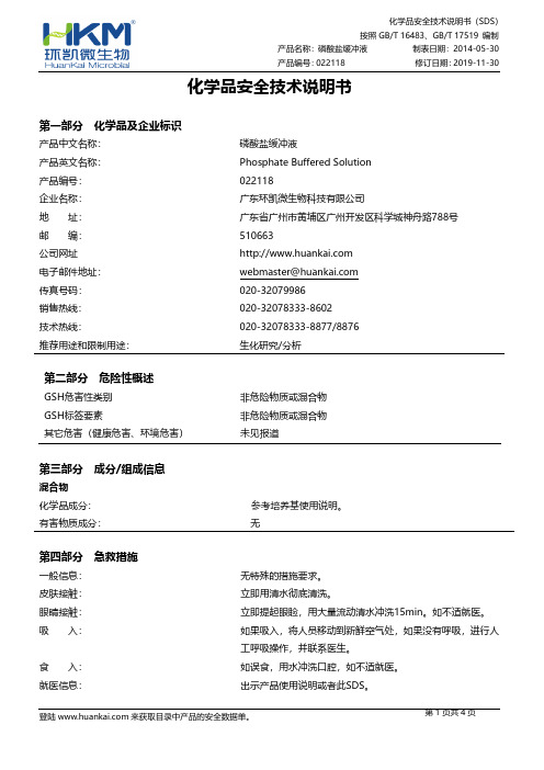
化学品安全技术说明书第一部分化学品及企业标识产品中文名称:磷酸盐缓冲液产品英文名称:Phosphate Buffered Solution产品编号:022118企业名称:广东环凯微生物科技有限公司地址:广东省广州市黄埔区广州开发区科学城神舟路788号邮编:510663公司网址电子邮件地址:*********************传真号码:************销售热线:************-8602技术热线:************-8877/8876推荐用途和限制用途:生化研究/分析第二部分危险性概述GSH危害性类别非危险物质或混合物GSH标签要素非危险物质或混合物其它危害(健康危害、环境危害)未见报道第三部分成分/组成信息混合物化学品成分:参考培养基使用说明。
有害物质成分:无第四部分急救措施一般信息:无特殊的措施要求。
皮肤接触:立即用清水彻底清洗。
眼睛接触:立即提起眼睑,用大量流动清水冲洗15min。
如不适就医。
吸入:如果吸入,将人员移动到新鲜空气处,如果没有呼吸,进行人工呼吸操作,并联系医生。
食入:如误食,用水冲洗口腔,如不适就医。
就医信息:出示产品使用说明或者此SDS。
第六部分 泄露应急处理个人防护:穿个人实验服,佩戴手套和口罩,避免吸入干粉。
环境保护措施:用湿布和地拖擦拭干净。
清洁/收集措施:保持干燥。
迅速清洗弄脏的区域。
第七部分 操作处置与储存安全操作注意事项:防止粉尘扬起,应提供通风设备。
储存注意事项:贮存于避光、干燥处,用后立即旋紧瓶盖。
第八部分 接触控制/个人防护职业接触限值没有已知的国家规定的暴露极限。
工程控制:提供安全淋浴和洗眼设备个人保护措施呼吸系统防护:在通风橱里称取产品,佩戴口罩。
眼睛防护:佩戴安全眼镜。
身体防护:穿实验室服。
手防护:戴防化学品手套。
其他防护:常规的工业卫生操作,工作后及时清洗双手。
第九部分 理化特性外观:粉末 pH 值: 7.3±0.1 颜色:白色 气味: 特征性 熔点:无数据资料 沸点: 无数据资料 燃点:无数据资料 闪点: 无数据资料 爆炸限度下限:无数据资料 上限: 无数据资料 热分解:无数据资料 溶解性:按产品使用说明上的用量比例加蒸馏水,加热煮沸至完全溶解,溶液呈无色澄清无沉淀。
MAX31785中文资料
_________________________________________________________________Maxim Integrated Products __1本文是英文数据资料的译文,文中可能存在翻译上的不准确或错误。
如需进一步确认,请在您的设计中参考英文资料。
有关价格、供货及订购信息,请联络Maxim 亚洲销售中心:10800 852 1249 (北中国区),10800 152 1249 (南中国区),或访问Maxim 的中文网站: 。
6通道智能风扇控制器MAX3178519-5703; Rev 0; 12/10+表示无铅(Pb)/符合RoHS 标准的封装。
T = 卷带包装。
*EP = 裸焊盘。
概述MAX31785是一款闭环多通道风扇控制器。
自动闭环风扇控制架构将风扇控制在尽可能低的转速,从而节省系统功率。
低风扇转速的其它优势包括:有效降低可闻噪声和更长的风扇寿命、更少的系统维护。
根据用户可编程查找表(LUT),器件根据11个温度传感器中的一个或多个传感器测量值,自动调节6个独立风扇的转速。
也可以由外部主机手动控制风扇转速,器件自动调整风扇转速。
器件具有风扇状况诊断功能,帮助用户预防将要发生的风扇故障。
器件还可监测多达6路远端电压。
应用网络交换机/路由器基站服务器智能电网系统工业控制定购信息特性S 6路独立的风扇控制通道 支持3线和4线风扇 自动闭环风扇转速控制 基于RPM 或PWM 控制 可选手动控制模式快速、慢速PWM 频率选项 风扇交替启动,缓解电源压力 双转速计(支持12个风扇) 风扇故障检测 风扇运转状态监测 非易失风扇运转时间表S 支持多达11个温度传感器6个外部温度二极管,带有串联电阻自动抵消功能 1个内部温度传感器 4个I 2C 数字温度传感器对所有温度传感器进行故障检测S 6路ADC 测量远端电压S PMBus™兼容命令接口S I 2C/SMBus™兼容串行总线,带有总线超时功能S 板载非易失故障记录和默认配置设置S 无需外部时钟S +3.3V 供电PMBus 是SMIF, Inc.的商标。
AD7715资料

1. The AD7715 consumes less than 450␣ µA in total supply current at 3 V supplies and 1␣ MHz master clock, making it ideal for use in low-power systems. Standby current is less than 10␣ µA. 2. The programmable gain input allows the AD7715 to accept input signals directly from a strain gage or transducer removing a considerable amount of signal conditioning. 3. The AD7715 is ideal for microcontroller or DSP processor applications with a three-wire serial interface reducing the number of interconnect lines and reducing the number of opto-couplers required in isolated systems. The part contains on-chip registers which allow software control over output update rate, input gain, signal polarity and calibration modes. 4. The part features excellent static performance specifications with 16-bits no missing codes, ± 0.0015% accuracy and low rms noise (<550␣ nV). Endpoint errors and the effects of temperature drift are eliminated by on-chip calibration options, which remove zero-scale and full-scale errors.
执行器CN7505_CN7510手册

行程调节
在调节控制模式下,当端子4提供给执行器24V电压信号时, 执行器将忽略端子3给出的信号,将50%的行程默认为最大行 程(见表3)
反馈信号
在接线正确的前提下(见图10、图11和图12),执行器通过 端子5提供其所在位置的反馈信号。
N05,N10 系列调节及浮点控制风门执行器
如表3所示:调节控制模式下,通过调节功能选择开关,导杆 的动作(”停止”、”逆时针旋转到最大角度”、”顺时针旋转到最 大角度”、”旋转到指定位置”或”在50%的行程内旋转”)将根据 端子3、端子4的不同连接而改变。
控制信号
端子3
端子4
开
开
开
24 Vac/dc
CN7510
5 VA / 2 W
控制信号 调节 浮点/开关
(0)2...10 Vdc 24 Vac/dc
环境条件 运行温度 储藏温度 相对湿度
安全指标 防护标准 保护等级 过载级别
使用寿命 全程 复位
风门连杆 圆型连杆 方型连杆 连杆长度
辅助开关(选配) 等级 触点
扭距
旋转角度
尺寸
重量
噪音
-5...+140 °F (-20...+60 °C) -22...+176 °F (-30...+80 °C) 5...95%, 无凝露
特点
• 手动调节位置 • 机械末端限位 • 可拆卸的电气连接盒 • 多种安装方向 • 可通过功能开关选择调节或浮点控制模式
技术参数
电压范围 额定电压
24 Vac/dc -15%/+20%, 50/60 Hz 24 Vac/dc, 50/60 Hz
PO015-SW3577全码表及修改意见-PP样确认2023-5

1/2
1/2
1/2
31 1/2
32
32 1/2
33
后身长 从后中领
1/2
1/2
NA
38
40
43
46 胸围 夹下1"
1/2
1/2
1/2
15 1/2
16
16 1/2
17
腰位置距高肩点
1/2
1/2
NA
36
38
பைடு நூலகம்41
44 腰围
1/2
1/2
NA
46
48
51
54
下摆开口 沿卷边缘拉量
1/4
1/4
0
1 1/2
1 1/2
PRE PRODUCTION
Version 1
POM
Description
+ Tol - Tol Grade
S
M
L
XL
! L0011 BACK LENGTH FROM CBN ! W0010 CHEST CIRCUMFERENCE @ 1" FROM/AH TM ! L0040 WAIST PLACEMENT FROM HPS ! W0020 WAIST CIRCUMFERENCE @ WAIST PLACEMENT ! W0050 SWEEP OPENING ALONG HEMLINE TM EXTENDED ! L0100 SHOULDER SLOPE ! L0120 FORWARD SHOULDER SEAM PLACEMENT ! W0080 ACROSS SHOULDER ! W0090 ACROSS BACK @ 5" F/HPS ! W0100 ACROSS FRONT @ 5" F/HPS ! S0012 SLEEVE LENGTH FROM CBN ! S0070 ARMHOLE DEPTH F/HPS ! S0100 UPPER ARM @ 1" FROM ARMHOLE ! S0120 SLEEVE OPENING ! C0010 NECK WIDTH ! C0030 FRONT NECK DROP F/HPS ! C0020 BACK NECK DROP F/HPS ! C0050 NECKLINE LENGTH ! C0040 COLLAR LENGTH @ OUTER EDGE ! C0060 COLLAR WIDTH @CBN ! H0010 HOOD OPENING ! H0020 HOOD WIDTH @ 5" F/TOP, EXCLUDING FUR ! H0030 HOOD NECKLINE LENGTH ! P0060 POCKET PLACEMENT F/HPS ! P0070 POCKET PLACEMENT F/CF @ TOP POINT ! PO096 POCKET PLAC. F/CF @ BOTTOM POINT ! P0091 POCKET OPENING HEIGHT ! B0020 BELT WIDTH ! B0030 FRONT BELT BTN PLC. FR HPS TO BTN CTER ! B0032 BELT LOOP PLACEMENT F/HPS @ BACK ! S0200 SLEEVE TAB LENGTH ! S0210 SLEEVE TAB WIDTH
7085——精选推荐
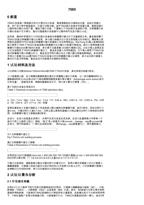
70850 前言7085铝合金是一种超高强可热处理强化铝合金,具有很高的比强度和比刚度,且加工性能优异,已广泛应用于航空航天、轨道车辆等领域。
由于7000系铝合金中铜含量较高,使其在熔焊过程中的热裂纹倾向严重,增加了熔焊难度,严重制约了7000系铝合金的应用。
搅拌摩擦焊在焊接铝合金时优势明显,能够彻底避免铝合金熔焊过程中的气孔及热裂纹问题。
近年来,国内外学者已针对7000系铝合金的搅拌摩擦焊接进行了大量研究工作。
姜玉恒开展了7050铝合金搅拌摩擦焊接试验研究,并对接头的微观组织及力学性能进行分析[1]。
傅田等人采用盲孔法研究7075铝合金搅拌摩擦焊接焊后残余应力分布特征[2]。
Wei Feng Xu等人采用EBSD 技术研究了7085-T7452铝合金双面搅拌摩擦焊缝显微组织的演变特征[3]。
林贤军采用双面搅拌摩擦焊焊接42mm厚7B05铝合金,并获得了强度系数为0.9的焊接接头[4]。
汤化伟等人采用正交试验方法研究了7055搅拌摩擦焊接工艺,重点关注接头力学性能[5]。
张华等人研究了7050铝合金搅拌摩擦焊接头的腐蚀行为,重点关注不同焊接热输入对接头腐蚀性能的影响[6]。
本文采用不同工艺参数对6 mm厚7085-T7452铝合金进行搅拌摩擦焊接试验研究,并对比分析焊接接头微观组织及力学性能,重点关注焊缝区域强化相的分布特征。
1 试验材料及方法试验材料为规格300mm×100mm×6mm的7085-T7452铝合金,其化学成分如表1所示。
为寻找直接证据,也为明确右骶棘肌粗大是代偿性增粗还是损伤所致,进一步行腰椎MRI检查。
横断面MRI可见L4/L5及L5/S1节段右骶棘肌横径及面积明显增大(Advantage work-station自带软件测量),但信号正常,明确右骶棘肌无损伤,同时未见黄韧带肥厚(图4)。
表1 7085铝合金化学成分%Table 1 Chemical composition of 7085 aluminiun alloyw(Zn)7.2 w(Mg)1.5 w(Cu)1.5 w(Ti)0.04 w(Mn)0.001 w(Cr)0.003 w(Fe)0.05 w(Si)0.04 w(Zr)0.11 w(Al)余量采用正面定位+正面焊接的工艺方法完成对接试板的搅拌摩擦焊接,如图1所示。
派克液压中文样本

液压注意 – 用户方责任 错误或不当地选择或使用本样本或有关资料阐述的产品,可能会导致人生伤亡及财产损失! 本样本以及其它由派克汉尼汾公司及其子公司、销售公司与授权分销商所提供的资料,仅供用户专业技术人员在对产品和系统的选型进行深入调查考证时参考。
用户应全面分析自身设备的运行工况、适用的工业标准,并仔细查阅现行的样本,以详细地了解产品及系统的相关信息,通过自己的分析和试验,对产品及系统的独立的最终选择负责,确保能满足自身设备的所有性能、耐用性、维修型、安全性以及预警功能等要求。
对于派克或其子公司或授权分销商而言,应负责按用户提供的技术资料和规范,选择和提供适当的元件或系统,而用户则应负责确定这些技术资料和规范对其设备的所有运行工况和能合理预见的使用工况是否充分和准确。
目录目录页次概述 1 订货代号 2 技术参数 4 变量控制器 5 控制选项 “C”, 压力限定(恒压)变量控制器 5 控制选项 “L”, 负载传感及压力限定变量控制器 6 控制选项 “AM”, 带遥控口的标准型先导式压力限定变量控制器 7 控制选项 “AN”, 带ISO 4401 NG06先导阀安装界面的先导式压力限定变量控制器 8 控制选项 “AE”及“AF”, 带电磁比例调节的先导式压力限定变量控制器 9 控制选项 “AMT”, “ALT”及“LOT”, 带最高压力限定的扭矩限定(恒功率)变量控制器 10 P1性能特性 11典型流量特性 11 典型总效率特性 13 典型轴输入功率特性 15 典型噪声特性 18 典型轴承寿命 20 PD性能特性 22典型流量特性 22 典型总效率特性 24 典型轴输入功率特性 26 典型噪声特性 29 典型轴承寿命 31 安装尺寸 33 P1/PD 018 33 P1/PD 028 36 P1/PD 045 40 P1/PD 060 44 P1/PD 075 49 P1/PD 100 54 P1/PD 140 59 变量控制器安装尺寸 65 可提供的扩展的液压产品 75派克汉尼汾备记派克汉尼汾概述简介, 优点派克汉尼汾简介 • 开式回路用轴向柱塞式变量液压泵 • 中压,连续工作压力280 bar • 高驱动转速型,适用于行走机械; 低噪声型,适用于工业应用 • 静音及高效的控制效能 优点 • 总结构尺寸紧凑 • 低噪声• 流量脉动小,进一步降低噪声• 采用弹性密封,不使用密封垫,从而避免外泄漏的产生• 总效率高,功耗小,减小发热• 采用带无泄漏调节装的简单变量控制器 • 符合SAE 及ISO 标准的安装法兰及油口 • 采用圆锥滚柱轴承,使用寿命长 • 全功率后驱动能力• 后部或侧面油口配置可选• 泄油口的配置对水平安装及驱动轴向上垂直安装均适用• 带有最大及最小排量调节选项 • 具有壳体至吸口单向阀选项,可延长轴封寿命 • 使用、维修方便 脉动容腔技术下列图表所示为侧向油口配置P1/PD 18, 28及45泵采用 “脉动容腔” 技术的效果,脉动容腔可降低泵出口处的压力脉动幅值40-60%,这样,无需增加成本来加装噪声缓冲元件,便可大大降低液压系统的整体噪声,P1系列 PD 系列出口压力p / bar平均压力脉动 / b a rP1 045出口压力脉动2600 rpm 无脉动容腔2600 rpm 带脉动容腔订货代号18 ml, 28 ml, 45ml派克汉尼汾P 类型 01 驱动轴 转向R 5密封材料E 油口配置0 壳体-吸口 单向阀 0 排量调节 018 排量 S 安装法兰 及油口 S 轴封 M 应用范围A 设计系列0 通轴驱动选项 C0控制选项0附加控制选项 00油漆 00修改代号系列 P D * 仅适用于045排量, “S”型安装法兰及油口00 标准型, 无修改M2 按要求修改 代号修改代号 * 适用于028及045排量 ** 仅适用于045排量 代号设计系列 A 现行设计系列5 氟碳橡胶 (FPM) 代号密封材料 A 82-2 SAE A M33x2 M27x2 BSPP 1/4”, 3/8” 101-2 SAE B M42x2 M27x2 BSPP 1/4”, 1/2” 101-2SAE B M48x2M33x2Ø38/25DN51/25BSPP 1/4”, 1/2”B ISO M33x2 M27x2 BSPP 1/4”,3/8”ISO M42x2 M27x2 BSPP 1/4”, 1/2” ISO M48x2M33x2Ø38/25DN51/25BSPP 1/4”, 1/2”代号 018排量 028排量 045排量 安装法兰及油口 安装 法兰 螺纹 油口 辅助 油口 安装 法兰 螺纹 油口 辅助 油口 安装法兰螺纹油口法兰 油口辅助 油口 S 82-2 SAE A SAE 16/12 SAE 4/6 101-2 SAE B SAE 20/12 SAE 4/8 101-2SAE B SAE 24/16Ø38/2561系列SAE 4/10M ISO M33x2 M27x2 M12x1.5 M16x1.5 ISO M42x2 M27x2 M12x1.5 M22x1.5 ISO M48x2M33x2Ø38/25DN51/25M12x1.5M22x1.5代号 018驱动轴 028驱动轴 045驱动轴 01 SAE A 11T 花键SAE B-B 15T 花键 SAE B-B 15T 花键02 SAE 19-1平键Ø0.75” SAE B-B 平键Ø1” SAE B-B 平键Ø1” 08— SAE B 13T 花键 SAE B 13T 花键 04 ISO/DIN 平键, Ø20ISO/DIN 平键, Ø25ISO/DIN 平键, Ø25 06 SAE A 9T 花键— — PD 工业液压用 代号 系列P1 行走机械用 代号 排量 018 18 ml/rev (1.10 in 3/rev) 028 28 ml/rev (1.71 in 3/rev) 045 45 ml/rev (2.75 in 3/rev) 代号 类型 P 开式回路用变量柱塞泵 U*通用 代号应用范围 S 工业液压 (PD) M 行走机械 (P1) R 顺时针 (右转)L 逆时针 (左转)代号 转向 代号 轴封 S 单唇轴封 * 并不具有控制功能,仅在运输时予以防护,详情见第7页的控制说明。
1-848077-7中文资料

1-848077-7 Product DetailsHome | Customer Support | Suppliers | Site Map | Privacy Policy | Browser Support© 2008 Tyco Electronics Corporation All Rights Reserved SearchProducts Documentation Resources My Account Customer SupportHome > Products > By Type > High Voltage LGH Products > Product Feature Selector > Product DetailsNo Image Available1-848077-7Active LGH Single-Pin Connectors and CableAssembliesNot reviewed for RoHS ComplianceProduct Highlights:?Lead Assembly?40 kVDC Operating Voltage?Lead Assembly Type = Double-End?Assembly Length = 14,503.40 mm?Barrel Depth = 45.97 mmView all Features | Find SimilarProductsCheck Pricing &AvailabilitySearch for ToolingProduct FeatureSelectorContact Us AboutThis ProductQuick LinksDocumentation & Additional InformationProduct Drawings:?LEAD ASSY DBL END, LGH-3 SHIELDED & GLASS BRAIDCOVERED(PDF, English)Catalog Pages/Data Sheets:?None AvailableProduct Specifications:?Standard LGH Connectors, Series 1/2I, 1/2LI, 1I, 1LI...(PDF, English)Application Specifications:?None AvailableInstruction Sheets:?None AvailableCAD Files:?None AvailableList all Documents Additional Information:?Product Line InformationRelated Products:?ToolingProduct Features (Please use the Product Drawing for all design activity)Product Type Features:?Product Type = Lead Assembly?Mount Angle = Straight?Cap Material = Glass-Filled Epoxy?Shielded = Yes?Wire Size (mm²[AWG]) = 16Electrical Characteristics:?Operating Voltage (kVDC) = 40Body Related Features:?Lead Assembly Type = Double-End?Assembly Length (mm [in]) = 14,503.40[571.434]?Barrel Depth (mm [in]) = 45.97 [1.810]?Positive Stop Ferrule = Without?Wire Color = White (Standard)?Cap Color = Green?Ground Lead Wire Color = Black?Ground Lead Wire Diameter = .050 NOM?Ground Lead Wire Insulation = Teflon?Ground Wire Size (AWG) = 22?Wire Diameter (mm [in]) = 8.64 [0.340]?Wire Insulation = Silicone Industry Standards:?RoHS/ELV Compliance = Not reviewed forELV/RoHS compliance?Lead Free Solder Processes = Not reviewed forlead free solder processOther:?Brand = AMPProvide Website Feedback | Contact Customer Support。
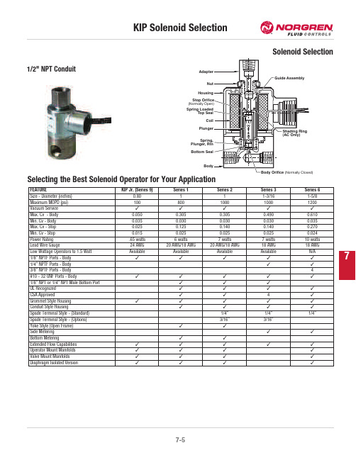
7-5 KIP 电磁阀选型说明书
7Selecting the Best Solenoid Operator for Your ApplicationStop(NormallyTopPlunger,Bottom1/2"NPT ConduitFEATURE KIP Jr.(Series9)Series1Series2Series3Series6Size-Diameter(inches)0.80111-3/161-5/8Maximum MOPD(psi)100800100010001200Vacuum Service¤¤¤¤¤Max.Cv-Body0.0500.3050.3050.4900.610Min.Cv-Body0.0350.0300.0300.0300.035Max.Cv-Stop0.0250.1250.1400.1400.270Min.Cv-Stop0.0150.0250.0250.0250.024Power Rating.65watts6watts7watts7watts10wattsLead Wire Gauge24AWG20AWG/18AWG20AWG/18AWG18AWG18AWGLow Wattage Operators to1.5Watt Available Available Available Available N/A1/8"NPTF Ports-Body¤¤¤¤¤1/4"NPTF Ports-Body¤¤3/8"NPTF Ports-Body4#10-32UNF Ports-Body¤¤¤¤¤1/8"NPT or1/4"NPT Male Bottom Port¤¤¤UL Recognized¤¤¤¤CSA Approved¤¤4¤Grommet Style Housing¤¤¤¤¤Conduit Style Housing¤¤¤¤Spade Terminal Style-(Standard)1/4"1/4"1/4"Spade Terminal Style-(Options)3/16"3/16"Yoke Style(Open Frame)¤¤Side Metering¤¤Bottom Metering¤¤Extended Flow Capabilities¤¤¤¤¤Operator Mount Manifolds¤¤¤¤Valve Mount Manifolds¤¤¤¤Diaphragm Isolated Version¤¤¤¤7U 240115-0251-24VDC*CoilsAll standard KIP valves are supplied with a Class “B”dry tape wound coil construction with 24"black leads,P/N (01)in the ordering system,unless otherwise specified.When using this chart below note the available housing styles and the series in which coils are available.The following chart shows all coil options readily available,for other options in OEM quantities consult KIP.Non-standard voltages,leadwire lengths,other lead wire types and colors,may require minimum quantities.KIP standard voltages:12VDC,24VDC,24/60,120/60,110/50,220/50,240/60.Lead wire type -AWG 20on Series 1and 2AWG 18on Series 1and 2with free standing molded coil AWG 18on Series 3and 6Coil classification -Class B =130°C or 266°F Class F =155°C or 311°F Class H =180°C or 356°F**For Class H coils change the second digit to a 3.Consult KIP for minimum order quantities.***Full wave rectification7 KIP Part Identification Numbering(PIN)System For ValvesThe KIP part number provides information about every aspect of the product it represents.The first letter is an optional prefix which identifiesUL recognized,oxygen or low wattage.The following numbers identify series,ports,housing style,material,valve function,orifice,seal,coil construction and coil temperature,in that order.The numerical value for each respective category represents one of multiple options.Where possible,the organization of this KIP catalog presents information in the order of the part identification number.You may use the number as a guide to finding information within the catalog.The following chart is the key to understanding the KIP Part Identification Number.UYABCDG7=#10-32UNF8=3/8"NPT(f)1=Grommet2=1/2"NPT Conduit3=Yoke(d)4=Yoke w/bracket(d)7=Grommet w/bracket9=Slotted(e)0=Slotted w/bracket(e)BunaFluorocarbon®Neoprene®Low temperature BunaPolyurethane(2WNC only)Teflon®(2WNC only)Neoprene W®Ethylene Propylene(EPR(Food Grade)be usedmolded coil(e)=Slotted housing(used with31&51spade coiloption),available in Series2,3&ed withmolded coil61in Series2&3,and41in Series1.(f)=Available in Series6,2WNC only.(g)=Available in Series1&2diaphragm only.® Teflon and Neoprene are registered trademarks of E.I. Dupont De Nemours Co.*Available in Series 1, 2 & 3 for 2-Way Normally Closed, 3-Way Normally Closed and 3-Way Multi-Purpose functions.7Series 6Note: Series 6 manifold mount 3-Way valves have a 1/4" NPTF adapter as standard. 1/8" NPTF available upon request.** Manifold Mount valve has maximum 400 MOPD rating for UL recognition.† These valves are supplied with 3/8" NPTF ports.Series 6Orifice Diameter Cv Factor MOPD (psi)Standard Valve Body Grommet Manifold Mount**Valve Body-Grommet Stainless Steel BrassBodyStop BodyStop 1/8" NPTF 1/4"NPTF 1/8" NPTF1/4"NPTF Stainless Steel Brass 2-Way Normally Open1/320.03510006410206510206411206511206610206611203/640.0506006410216510216411216511216610216611211/160.0953506410226510226411226511226610226611225/640.1402506410236510236411236511236610236611233/320.2001756410246510246411246511246610246611241/80.2951006410256510256411256511256610256611252-Way Nomally Closed1/320.03512006410106510106411106511106610106611103/640.05010006410116510116411116511116610116611111/160.0955006410126510126411126511126610126611125/640.1403006410136510136411136511136610136611133/320.2002006410146510146411146511146610146611141/80.2951506410156510156411156511156610156611155/320.3701106410166510166411166511166610166611163/160.435606410176510176411176511176610176611171/40.610306410186510186411186511186610186611183/80.9005—681019†—681119†——3-Way Normally Open1/321/320.0350.0254006410506510506411506511506610506611503/643/640.0500.0652506410516510516411516511516610516611511/161/160.0900.1152006410526510526411526511526610526611525/645/640.1350.1801756410536510536411536511536610536611533/323/320.1800.2101256410546510546411546511546610546611541/81/80.2750.240856410556510556411556511556610556611555/321/80.3700.240506410566510566411566511566610566611563/161/80.4550.240356410576510576411576511576610576611571/41/80.6500.240156410586510586411586511586610586611583-Way Normally Closed(For free vent,change fifth digit from 4 to 3)1/321/320.0350.0253006410406510406411406511406610406611403/643/640.0500.0652506410416510416411416511416610416611411/161/160.0900.1152006410426510426411426511426610426611425/645/640.1350.1801756410436510436411436511436610446611443/323/320.1800.2101256410446510446411446511446610456611451/81/80.2750.240856410456510456411456511456610466611465/321/80.3700.240506410466510466411466511466610476611473/161/80.4550.240306410476510476411476511476610486611481/41/80.6500.24015641048651048641148651148--3-Way Multi-Purpose1/321/320.0350.0252756410606510606411606511606610606611603/643/640.0500.0652006410616510616411616511616610616611611/161/160.0900.1151756410626510626411626511626610626611625/645/640.1350.1801256410636510636411636511636610636611633/323/320.1800.2101006410646510646411646511646610646611641/81/80.7500.240606410656510656411656511656610656611655/321/80.3700.240406410666510666411666511666610666611663/161/80.4550.240256410676510676411676511676610676611671/41/80.6500.240156410686510686411686511686610686611687Operator StandardBracket DimensionsManifold Mount ValveAB C D E F G H Series6 1.64(42)G- .97 (25)C- .80 (20)1.79(46)2.48(63)1.03(26)1.58(40)1-32 UN1/8-27 NPTF or 1/4-18NPTFA B C D E F Series 62.13 (54)1.97 (50).20 (5)2.63 (67)2.15 (55)2.68 (68)AB C D E F m n r Series 6 1.62(41)G-1.73 (44) 2.55(65)3.23(82)1.03(26)1.58(40)1/2 20UNF.31(8)1/8-27 NPTFor 1/4-18 NPTFC-1.56 (40)。
Gold Tuning Solution, Part Number 8500-7000 Safety
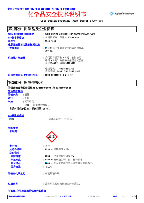
Gold Tuning Solution, Part Number 8500-7000*************(24小时)化学品安全技术说明书GHS product identifier 应急咨询电话(带值班时间)::供应商/ 制造商:安捷伦科技贸易(上海)有限公司中国(上海)外高桥自由贸易试验区英伦路412号(邮编:200131)电话号码: 800-820-3278传真号码: 0086 (21) 5048 2818Gold Tuning Solution, Part Number 8500-7000化学品的推荐用途和限制用途8500-7000部件号:安全技术说明书根据 GB/ T 16483-2008 和 GB/ T 17519-2013GHS化学品标识:金调谐溶液, 部件号 8500-7000推荐用途:有关环境保护措施,请参阅第 12 节。
物质或混合物的分类根据 GB13690-2009 和 GB30000-2013紧急情况概述液体。
无色。
无气味的。
H290 - 可能腐蚀金属。
物理状态:颜色:气味:GHS危险性类别警示词:警告危险性说明:H290 - 可能腐蚀金属。
:防范说明预防措施:P234 - 仅在原包装内保存。
事故响应:P390 - 吸收溢出物,防止材料损坏。
安全储存:废弃处置:不适用。
标签要素象形图金属腐蚀物 - 类别 1物理和化学危险可能腐蚀金属。
健康危害没有明显的已知作用或严重危险。
::与物理,化学和毒理特性有关的症状皮肤接触食入吸入没有具体数据。
没有具体数据。
没有具体数据。
:::延迟和即时影响,以及短期和长期接触引起的慢性影响短期暴露潜在的即时效应:无资料。
潜在的延迟效应:无资料。
潜在的即时效应:无资料。
长期暴露潜在的延迟效应:无资料。
环境危害:没有明显的已知作用或严重危险。
其他危害:没有已知信息。
物质/混合物美国化学文摘社(CAS)编号/其它标识号:混合物就供应商当前已知,在所适用的浓度中,没有其它对健康或环境有害的成分需要在本章节报告。
1736755中文资料
Extract from the onlinecatalogMDSTBV 2,5/ 4-G1-5,08Order No.: 1736755The figure shows a 10-position version of the producthttp://eshop.phoenixcontact.de/phoenix/treeViewClick.do?UID=1736755Header, nominal current: 10 A, rated voltage: 250 V, pitch: 5.08 mm, no. of positions: 4, mounting: Solderinghttp://Please note that the data givenhere has been taken from theonline catalog. For comprehensiveinformation and data, please referto the user documentation. TheGeneral Terms and Conditions ofUse apply to Internet downloads. Technical dataDimensions / positionsPitch 5.08 mmDimension a15.24 mmNumber of positions4Pin dimensions 1 x 1 mmHole diameter 1.4 mmTechnical dataInsulating material group IRated surge voltage (III/3) 4 kVRated surge voltage (III/2) 4 kVRated surge voltage (II/2) 4 kVRated voltage (III/2)320 VRated voltage (II/2)630 VConnection in acc. with standard EN-VDENominal current I N10 ANominal voltage U N250 VMaximum load current10 AInsulating material PAInflammability class acc. to UL 94V0Certificates / ApprovalsApproval logoCSANominal voltage U N300 VNominal current I N10 ACULNominal voltage U N300 VNominal current I N10 AULNominal voltage U N300 VNominal current I N10 ACertification CB, CSA, CUL, GOST, UL, VDE-PZIAccessoriesItem Designation DescriptionAssembly1755477MSTB-BL Keying cap, for forming sections, plugs onto header pin, greeninsulating materialMarking0804293SK 5,08/3,8:FORTL.ZAHLEN Marker card, printed horizontally, self-adhesive, 12 identicaldecades marked 1-10, 11-20 etc. up to 91-(99)100, sufficient for120 terminal blocksPlug/Adapter1734401CR-MSTB Coding section, inserted into the recess in the header or theinverted plug, red insulating materialAdditional productsItem Designation DescriptionGeneral1872716A-ICV 2,5/ 4-G-5,08Header, nominal current: 12 A, rated voltage: 250 V, pitch: 5.08mm, no. of positions: 4, mounting: Mounting rail1873074FKC 2,5/ 4-ST-5,08Plug component, nominal current: 12 A, rated voltage: 250V, pitch: 5.08 mm, no. of positions: 4, type of connection:Spring-cage connection1902136FKCT 2,5/ 4-ST-5,08Plug component, nominal current: 12 A, rated voltage: 250V, pitch: 5.08 mm, no. of positions: 4, type of connection:Spring-cage connection1873977FKCVR 2,5/ 4-ST-5,08Plug component, nominal current: 12 A, rated voltage: 250V, pitch: 5.08 mm, no. of positions: 4, type of connection:Spring-cage connection1873676FKCVW 2,5/ 4-ST-5,08Plug component, nominal current: 12 A, rated voltage: 250V, pitch: 5.08 mm, no. of positions: 4, type of connection:Spring-cage connection1777303FRONT-MSTB 2,5/ 4-ST-5,08Plug component, nominal current: 12 A, rated voltage: 250 V,pitch: 5.08 mm, no. of positions: 4, type of connection: Screwconnection1786420IC 2,5/ 4-G-5,08Header, nominal current: 12 A, rated voltage: 320 V, pitch: 5.08mm, number of positions: 4, mounting type: soldering 1785968ICV 2,5/ 4-G-5,08Header, nominal current: 12 A, rated voltage: 320 V, pitch: 5.08mm, number of positions: 4, mounting type: soldering 1757035MSTB 2,5/ 4-ST-5,08Plug component, nominal current: 12 A, rated voltage: 250 V,pitch: 5.08 mm, no. of positions: 4, type of connection: Screwconnection1776155MSTB 2,5/ 4-STZ-5,08Plug component, nominal current: 12 A, rated voltage: 250 V,pitch: 5.08 mm, no. of positions: 4, type of connection: Screwconnection1808832MSTBC 2,5/ 4-ST-5,08Plug component, nominal current: 12 A, rated voltage: 320 V,pitch: 5.08 mm, no. of positions: 4, type of connection: Crimpconnection1809527MSTBC 2,5/ 4-STZ-5,08Plug component, nominal current: 12 A, rated voltage: 320 V,pitch: 5.08 mm, no. of positions: 4, type of connection: Crimpconnection1769036MSTBP 2,5/ 4-ST-5,08Plug component, nominal current: 12 A, rated voltage: 250 V,pitch: 5.08 mm, no. of positions: 4, type of connection: Screwconnection1780002MSTBT 2,5/ 4-ST-5,08Plug component, nominal current: 12 A, rated voltage: 250 V,pitch: 5.08 mm, no. of positions: 4, type of connection: Screwconnection1792265MVSTBR 2,5/ 4-ST-5,08Plug component, nominal current: 12 A, rated voltage: 250 V,pitch: 5.08 mm, no. of positions: 4, type of connection: Screwconnection1792773MVSTBW 2,5/ 4-ST-5,08Plug component, nominal current: 12 A, rated voltage: 250 V,pitch: 5.08 mm, no. of positions: 4, type of connection: Screwconnection1917927QC 0,75/ 4-ST-5,08Plug components, 5.08 mm pitch, color: green, no. of positions 4,dimension a 15.24 mm1883271QC 1/ 4-ST-5,08Plug, nominal current: 10 A, rated voltage: 500 V, pitch: 5.08mm, number of positions: 4, connection method: Insulationdisplacement connection QUICKON1826306SMSTB 2,5/ 4-ST-5,08Plug component, nominal current: 12 A, rated voltage: 250 V,pitch: 5.08 mm, no. of positions: 4, type of connection: Screwconnection1853036TMSTBP 2,5/ 4-ST-5,08Plug component, nominal current: 12 A, rated voltage: 250 V,pitch: 5.08 mm, no. of positions: 4, type of connection: ScrewconnectionDrawingsDrilling diagramDimensioned drawingAddressPHOENIX CONTACT GmbH & Co. KGFlachsmarktstr. 832825 Blomberg,GermanyPhone +49 5235 3 00Fax +49 5235 3 41200http://www.phoenixcontact.de© 2008 Phoenix ContactTechnical modifications reserved;。
L7805中文资料_数据手册_参数

万联芯城-电子元器件采购网,提供一站式配套 ,解决物料烦恼,万联芯城销售电子元器件范围包括IC集成电路 ,电阻电容,二三极管,可进行一站式BOM表配单,客户只需访 问官网,联系在线客服提交BOM表,即可获得报价,万联芯城拥 有完善的产品供应链体系及现代化仓储系统,可满足多种BOMriptionThe L7805一系列三端positiveregulators可在- 220,- 220《外交政策》,3,D²PAK DPAK包和几个fixedoutput电压,大rangeof应用程序 使它有用。这些监管机构可以提供本地的cardregulation,L7805消除了与单点监管相关的分布问题。每一种类型都采用内部限流、热关 闭和安全区保护,使其基本上坚不可摧。如果提供足够的热量下沉,L7805可以提供超过1输出电流。虽然这些装置主要是作为固定电压 调节器设计的,但它们可以与外部元件一起使用,以获得可调电压和电流当前 1.5 A Output Output 电压 5 ;6;8;8.5;9;12;15;18 ;24 V Thermal 过载 protection Short 电路 protection Output 过渡 SOA protection 2% 输出 电压 公差 (A version) Guaranteed 扩展 温度 range(A version)设计considerationThe L78xx一系列固定L7805电压调节器的设计与热过载protectionthat关闭电路,当受到过度功率过载条件 下,内部短路保护,限制了最大电流电路将通过,输出晶体管安全区补偿,降低了输出短路电流thevoltage在通过增加晶体管。在许多低电流 应用中,不需要补偿电容器。但是,如果调节器与电源滤波器的连接长度较长,或者输出负载电容较大,则建议用电容绕过调节器输 入。应选择输入旁路电容器,以提供良好的高频特性,以确保在全负荷条件下稳定运行。0.33µF或更大钽、聚酯薄膜或其他电容器在高 频低internalimpedance应该选择。旁路电容器应该安装在尽可能短的引线直接越过稳压器输入端子。正常情况下,L7805由于调节阀没有 外部感应引线,应该使用良好的施工技术来尽量减少接地回路和引线阻力下降。运算放大器的添加允许调整到更高或中间值,同时保 持调节特性。通过这种布置获得的最小电压为2v,大于稳压器电压。图13中的电路可以通过添加一个短路感知电阻、RSC和一个附加的 PNP晶体管来修改,以提供对短路的电源保护。电流感知PNP必须能够处理三个终端调节器的短路电流,因此指定了一个四安培塑料功 率晶体管。
IOS-MAT-0054_CNv5
参考
本技术规范中化学品要求和测试所引用的标准,如欧盟指令,都适用标准、指令的最新版本,除非 另有说明。
本资料仅供参考,英文版本 IOS-MAT-0054 具有最终法律效力。
1 of 23 2009-10-26 Elsa Hou 译稿
表2. 实木、木基材料和天然材料的要求
物质
要求
测试方法
文件
硼及其化合物
不允许使用硼及其化合物。
在实木(包括实木拼板)、 污染限值:硼及其化合物的迁移 天然纤维、胶合板、层压 值:30 mg 硼/kg 板/弯曲木中
如果木材有涂层,在 SD 测试前应去除涂层。
DIN 53160(用人工 合成汗液进行萃取, 16小时,23 °C), 然后依照EN ISO 11885(ICP/AES分 析)
IOS-MAT-0054 第五版译文
原版本代号:
审稿人:Jason Liu, Teresa Xu, Sebrina Chen
AA-92520-5 2009-10-09
化合物和化学物质:对儿童产品与玩具的附加要求
内容
本规范阐述了宜家对所有儿童产品(包括玩具)的化合物和化学物质的附加要求。
关于此规范
本规范的目的是确保儿童产品和玩具在儿童使用时是安全的,因为儿童更为敏感,并且接触产品的 方式与成人不同(如吮吸和咀嚼)。
染料
不允许使用。
在印刷或上色的纸/纸板中 污染限值:每种染料10 mg/kg
甲醛(50-00-0)
甲醛含量不可高于30mg/kg。 EN 71-11
文件 SD
SD
2.3 纺织品
表4.对纺织品的要求
STEP7V55中文版简介5%d6%d0%ce%c4%b0%e6%bc%f2%bd%e9

SIMATIC编程软件件用于SIMATIC S7 / M7 / C7的STEP 7 V5.5编程软安装与使用注意事项该注意事项中包含的信息相对于其它文档来说是最新的。
请仔细阅读,此文本中包含了有关STEP 7 V5.5的安装与使用信息。
对该版本的重要修订以斜体显示,并标有注释“从该版本开始新增的内容”。
请注意,对于A4格式,所要打印文件的左右边距都设置成25 mm。
目录安装注意事项1发货清单2硬件要求3软件要求3.1运行环境3.2需要的存储空间3.3与其它软件产品的兼容性3.3.1Rational ClearCase配置管理工具3.3.2使用其它软件产品时的网络设置3.4在线文档4安装4.1安装STEP 7 V5.54.2升级旧版STEP 74.3STEP 7 V5.5许可证密钥4.4删除STEP 7 V5.54.5安装时的其它注意事项4.5.1使用滚轮鼠标4.5.2使用PC/PG通信卡时的注意事项使用注意事项(版本注释)5新版软件的新特性和所作的修改6组态和操作软件时的注意事项6.1STEP 7如何满足IEC标准6.2常规注意事项6.3使用网络驱动器6.4多用户操作6.5多重项目6.6交换不同版本的STEP 76.7库文件和实例项目6.8SIMATIC管理器6.9使用符号名6.10硬件配置(中央机架)6.11硬件配置(PROFIBUS DP)6.12硬件配置(PROFINET IO)6.13冗余I/O:通道间隔冗余6.14硬件诊断6.15MPI / PROFIBUS网络设置6.16SIMATIC M76.17梯形图、功能块图、语句表和参考数据6.18翻译文本6.19管理多语言文本6.20将S5程序转换成S7程序6.21将TI程序转换成S7程序6.22容错系统6.23使用外文字符集时的注意事项6.24使用SIMATIC Logon的注意事项6.25命令接口6.26TCI –工具调用接口6.27MS Windows 7操作系统的特性7文档注意事项8使用STEP 7中文版时的重要特性安装注意事装注意事项项以前请务本注意事项中包含您在安装STEP 7 V5.5时所需的重要信息,在安装该软件以前以前必详细阅读该注意事项。
API 7K 第5版中文版
7.7质量控制要求...................................................................15
8.2 质量控制人员资格...............................................................16
8.3测试设备.......................................................................16
5设计验证..........................................................................8
5.1总则............................................................................8
7焊接要求.........................................................................15
7.1总则...........................................................................15
9.7 活塞泥浆泵零部件...............................................................31
9.8绞车零部件.....................................................................55
7525中文资料

TOSGAGE Series
X-ray Thickness Gage
General
The X-ray thickness gage is used to measure the thickness of a strip continuously without contacting that strip. This gage uses the fact that the amount of radiation that passes through the strip varies with the thickness of that strip. The TOSGAGE-7525 is a high quality thickness gage for cold rolling achieving outstanding safety, operability, accuracy and cost-performance developed over many years. It has the following features. • Noise immunity is improved by digitizing the signals between the measuring head and the equipment cabinet.
TOSGAGE -7525
• The operation-PC uses Windows® NT, and is a user-friendly PC. • A newly-developed X-ray generator is used, providing extremely accurate measurement results with a quick response time. The TOSGAGE-7525 focuses X-ray beams finely in the strip width direction to improve thickness resolution in the strip width direction, and making it suited to measuring the shape of the section of measured materials. The TOSGAGE-7525 can also be used as a AGC backup for when the fixed thickness gage (TOSGAGE-7521/7522) has failed.
UL8750中文版,LED灯具国际标准
UL 8750用於燈具產品的發光二極體光源安全通則UL 8750 用於燈具產品的發光二極體光源LIGHT EMITTING DIODE (LED) LIGHT SOURCES FOR USEIN LIGHTING PRODUCTS這是用於燈具產品內的發光二極體光源的評估指南的第一版,適用於發光二極體作為光源的元件,例如發光二極體模組,發光二極體陣列、電源與控制電路。
也涵蓋了由最終產品製造商製作的發光二極體光源,它可以是產品的一部分或者是由其他光源廠商組裝到燈具產品內的零組件。
介紹1.適用範圍1.1下列要求是針對發光二極體作為任何1.3節所列的燈具產品光源,規範了最小的安全要求1.2發光二極體光源包含了下列的零組件:a)提供照明的單一發光二極體或是發光二極體陣列。
b)提供適當的電壓與電流使發光二極體運作的電源。
c)提供開關、閃爍或是其他控制發光二極體能量的控制電路。
1.3符合本規格要求的發光二極體光源,可作為符合下列標準要求的燈具產品的照明。
下列產品適用於600V以下的電源分支,並在於依照美國國家電工法規(ANSI/NFPA 70)內所列的非危險的環境下使用。
本規格要求也適用於發光二極體光源連接到如一般電池組、燃料電池等獨立電源的情況:a)燈具 UL 1598b)攜帶式燈具UL 153c)舞台與工作室照明UL 1573d)潛水用照明 UL 676e)游泳池照明UL 676f)軌道燈系統UL 1574g)號誌UL 48h)緊急照明燈與出口標示燈UL 924i)內置電子安定器電燈UL 1993j)逃生出口路徑標示系統照明UL 1994k)小夜燈UL 1786l)可撓式照明, UL 2388m)低電壓照明系統 UL 2108n)燈座配件 UL 496o)景觀用照明 UL 18381.4用於危險場所、健康照護、緊急或海軍用的LED照明產品應用,因具有其他額外的標準要求,並不包含在本評估指南中2.一般通則2.1零組件2.1.1除了2.1.2節的例外情形,本指南涵蓋的產品零組件必須符合該元件的要求。
(仅供参考)执行器CN7505_CN7510手册

如果功能选择指向浮点/开关控制时,并且接线选择有反馈信号 (见图11、12),一旦接通电源,执行器将逆时针旋转到最大角 度,再顺时针旋转到最大角度(见“调试”部分),完成后,将 按照控制信号运行到相应位置。
调节控制模式
如果功能选择指向浮点/开关控制时,并且接线选择有反馈信号 (见图10),一旦接通电源,执行器将逆时针旋转到最大角度, 再顺时针旋转到最大角度(见“调试”部分),完成后,将按照 控制信号运行到相应位置。
24 Vac/dc
开
控制信号
端子3
端子4
24 Vac/dc
开
24 Vac/dc
24 Vac/dc
表1. 浮点控制模式下的导杆动作说明
0[2]...10V ----
Dir 停止
CCW CW
开关设置
Service/Off 停止 停止 停止
表2. 开关控制模式下的导杆动作说明
0[2]...10V ---
Dir CW CCW
特点
• 手动调节位置 • 机械末端限位 • 可拆卸的电气连接盒 • 多种安装方向 • 可通过功能开关选择调节或浮点控制模式
技术参数
电压范围 额定电压
24 Vac/dc -15%/+20%, 50/60 Hz 24 Vac/dc, 50/60 Hz
以下所有参数均在额定电压下测得
功率
CN7505
5 VA / 2 W
或低于最小控制信号加0.24V),再次调试后,执行器将在 机械限位的两端各自停留3秒以上;无论如何,执行器将 始终以机械限位的两端位置作为旋转的极限。
行程调节
在调节控制模式下,当端子4提供给执行器24V电压信号时, 执行器将忽略端子3给出的信号,将50%的行程默认为最大行 程(见表3)
Racor 73、75、77和79系列聚合油筛 水分离器说明书
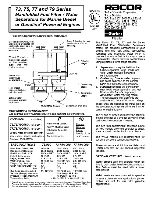
Parker Hannifin Corporation Racor Division P.O.Box 3208,3400Finch Road Modesto,CA 95353USA 209/521--7860800/344--3286FAX 209/529--3278Filtration Optionalprobes are for all bowls. 1.SeparationStage Internal flow check valvesare standard.2.CoalescingStage3.FiltrationStageDie--cast and brackets electrostatic excellent resistance.High--impact engineered collection The Racor 73,75,77and 79Series Manifolded Fuel Filter/Water Separators protect the precision components of your engine from dirt,rust,algae,asphaltines,varnishes and especially water which is prevalent in todays fuel tanks simply due to condensation.Racor removes contaminants using a patented three stage process:1.Separation:Using the fuel flow,the turbine separates large solids and ’free’water through enhanced centrifugal force.2.Coalescing:Smaller water droplets and solids coalesce on the conical baffle and fall to the collection bowl.3.Filtration:Engines will benefit from near 100%water separation and fuel filtration with Racor’s proprietary Aquabloc TM water repelling media.The replaceable filter elements are available in 2,10and 30micron ratings.These units are designed for installation on the suction (vacuum)side of the fuel transfer pump for best efficiency.The 75and 79Series units have the ability to isolate one filter at a time for servicing,even during engine operation,if needed.The see--thru contaminant collection bowls on ’MA’models allow the operator to check water and solid contamination at a glance.The ’MAM’models are recommended for gasoline or severe service applications.These models are all UL Marine Listed and USCG Accepted for use aboard inspected vessels.OPTIONAL FEATURES:See Accessories.Water probes alert the operator when it’s time to drain water from the collection bowls.This feature must be used with a water detection kit.Metal bowls are recommended for gasoline or severe diesel service applications.(Water probes are not for use with gasoline applications).75/900Flow Rate,GPH /LPH 180/681360/1363540/2044Replacement Element 2040Series 2020Series 2020SeriesFuel Ports,SAE J4763/4”--14NPT 3/4”--14NPT 3/4”--14NPTHeight,inches /mm 22/55922/55922/559Depth,inches /mm 12.5/31812.5/31812.5/318Width,inches /mm 15/381mm 15/381mm 22/559mmWeight,Dry,lbs./kgs.25/11.330/13.653/24Clean Pressure Drop*PSI 1.7 1.7 2.5kpa 11.711.717.2Overhead space required 5”/127mm 10”/254mm 10”/254mmVacuum (Pump),maximum 28.5inHg./96.5kPaPressure (Head),maximum 15PSIG /103kPaTemperature Rating --40o /+255o F /--40o /+121o C77,79/1000SPECIFICATIONS *Specifications result from tests conducted at the maximum flow rate.Simplified Flow RateFormula for Medium &Heavy Duty Engines:Horsepower X .36=Approximate (GPH)fuel pump flow rate.Consult your engine manufacturer for exact specifications.PART NUMBER IDENTIFICATION:The example below illustrates how the part numbers are constructed.drain plug.for easyof lid for75and 79feature ball for filter even engine *Gasoline applications should specify metal bowls.73,75/1000U L MARINE LISTED168YINSTALLATION INSTRUCTIONSWHEN POSITIONING THE UNIT:1.The Racor unit should be installed on the suction(vacuum)side of the fuel transfer pump for optimum water separatingefficiency.See the illustration below.2.To keep fuel line restriction to a minimum,locate the unit between the horizontal planes of the bottom of the fuel tank andthe inlet of the fuel pump,if at all possible.Note:If the Racor unit is mounted lower than the fuel tank,head pressure will be placed on the unit.In these applicationsa valve should be installed at the fuel tank outlet.This is a necessary precaution for fuel system plumbing.3.For element servicing,maintain an overhead clearance of5”(127mm)for the75/900and10”(254mm)for all other models. BEFORE INSTALLING THE UNIT:1.Ensure fuel port fittings are in hand along with fuel line and all needed installation tools and materials.2.Maintain a safe working environment.Obtain good ventilation,lighting and Do not smoke or allow open flame near theinstallation.The engine must be off.MOUNTING HOLE PATTERNS:Use the dimensions below when drilling holes or positioning the unit.INSTALLING THE UNIT:pletely remove any suction side filter(s)in the fuel line between the fuel tank and fuel pump,if possible.Leaving thesefilters in place will only add to fuel line restriction.Filter heads cast into the engine block or that are non--removable should be serviced with a new element and left in place.e maximum size fuel line where possible to reduce potential fuel line restriction.Avoid making sharp bends with flexiblefuel line as kinks may occur.3.To keep fuel flow restriction values to a minimum,avoid the use of two45o fittings where one90o elbow fitting will work.4.When routing fuel hose,avoid moving surfaces,sharp edges and hot surfaces such as exhaust piping.FUEL SYSTEM PRIMING:Remove the lid and T--handle.Fill the unit with clean fuel and coat the lid seal with fuel as well.Replace the lid and snugly tighten the T--handle by hand ONLY.If applicable,refer to the equipment operator’s service manual to complete the fuel priming/bleeding procedure.Start the engine and check the installation for potential leaks.TROUBLESHOOTING PROCEDURES:A major cause of poor starting or power loss is the result of a fuel system air leak or a clogged filter element.If your unit will not prime,fails to hold a prime or if air bubbles are visible in the see--thru bowl,first check that the lid T--handle and drain are properly tightened.Next,check all fitting connections and ensure none of the fuel lines are pinched or clogged with contaminants.If your fuel tank is equipped with an in--tank strainer,check it for potential clogging.If problems persist and the filter element is new,call your Racor dealer or Racor Customer Service for assistance at800/344--3286,PST.ToTOof1.2.3.TOis1.2.3.4.NOTE:RACOR ELECTRICAL OPTIONS ARE RECOMMENDED FOR USE WITH DIESEL FUEL APPLICATIONS. Water Probe.Racor units(except for those in gasoline applications)can be specified with a water probe in the collection bowls.The probe senses continuity values and must be used with a special electronic detector to function properly.Due to the various models available,these electronic detectors are sold separately and installation instructions are supplied with each kit.Only one detector is needed for each filter assembly(up to3probes).Order kits from your Racor Dealer.Water Detection Kit#RK20726is a12or24vdc gauge type module which illuminates an LED and sounds a momentary horn when water is detected.The face is hermetically sealed and corrosion resistant with non--glare black dial with white characters.The backside has three#8--32threaded posts for terminal attachment.Fits21/16”diameter panel openings.Hardware&instructions included.Wire& terminals are customer supplied.U.L.approved circuitry for marine diesel applications.。
