MMST4126-7;MMST4126-7-F;中文规格书,Datasheet资料
MW6S004NT1;中文规格书,Datasheet资料

RF Power Field Effect TransistorN-Channel Enhancement-Mode Lateral MOSFETDesigned for Class A or Class AB base station applications with frequencies up to 2000 MHz. Suitable for analog and digital modulation and multicarrier amplifier applications.•Typical Two-Tone Performance @ 1960 MHz, 28 Volts, I DQ = 50 mA, P out = 4 Watts PEP Power Gain — 18 dB Drain Efficiency — 33%IMD — -34 dBc•Typical Two-Tone Performance @ 900 MHz, 28 Volts, I DQ = 50 mA, P out = 4 Watts PEP Power Gain — 19 dB Drain Efficiency — 33%IMD — -39 dBc•Capable of Handling 5:1 VSWR, @ 28 Vdc, 1960 MHz, 4 Watts CW Output Power Features•Characterized with Series Equivalent Large-Signal Impedance Parameters •On-Chip RF Feedback for Broadband Stability •Integrated ESD Protection •RoHS Compliant•In Tape and Reel. T1 Suffix = 1000 Units per 12 mm, 7 inch Reel.Table 1. Maximum RatingsRatingSymbol Value Unit Drain-Source Voltage V DSS -0.5, +68Vdc Gate-Source Voltage V GS -0.5, +12Vdc Storage Temperature Range T stg -65 to +150°C Operating Junction TemperatureT J150°CTable 2. Thermal CharacteristicsCharacteristicSymbol Value (1,2)Unit Thermal Resistance, Junction to CaseCase Temperature 76°C, 4 W PEP , Two-Tone Case Temperature 79°C, 4 W CWR θJC8.88.5°C/WTable 3. ESD Protection CharacteristicsTest MethodologyClass Human Body Model (per JESD22-A114)1C (Minimum)Machine Model (per EIA/JESD22-A115) A (Minimum)Charge Device Model (per JESD22-C101)IV (Minimum)1.MTTF calculator available at /rf. Select Software & Tools/Development Tools/Calculators to access MTTF calculators by product.2.Refer to AN1955, Thermal Measurement Methodology of RF Power Amplifiers. Go to /rf. Select Documentation/Application Notes - AN1955.Document Number: MW6S004NRev. 4, 6/2009Freescale Semiconductor Technical DataMW6S004NT1Table 4. Moisture Sensitivity LevelTest MethodologyRating Package Peak TemperatureUnit Per JESD 22-A113, IPC/JEDEC J-STD-0203260°CTable 5. Electrical Characteristics (T A = 25°C unless otherwise noted)CharacteristicSymbolMinTypMaxUnitOff CharacteristicsZero Gate Voltage Drain Leakage Current (V DS = 68 Vdc, V GS = 0 Vdc)I DSS ——10μAdc Zero Gate Voltage Drain Leakage Current (V DS = 28 Vdc, V GS = 0 Vdc)I DSS ——10μAdc Gate-Source Leakage Current (V GS = 5 Vdc, V DS = 0 Vdc)I GSS——500nAdcOn CharacteristicsGate Threshold Voltage(V DS = 10 Vdc, I D = 50 mAdc)V GS(th) 1.22 2.7Vdc Gate Quiescent Voltage(V DS = 28 Vdc, I D = 50 mAdc)V GS(Q)— 2.7—Vdc Fixture Gate Quiescent Voltage (1)(V DD = 28 Vdc, I D = 50 mAdc, Measured in Functional Test)V GG(Q) 2.23 4.2Vdc Drain-Source On-Voltage(V GS = 10 Vdc, I D = 50 mAdc)V DS(on)—0.270.37VdcDynamic CharacteristicsReverse Transfer Capacitance(V DS = 28 Vdc ± 30 mV(rms)ac @ 1 MHz, V GS = 0 Vdc)C rss —21—pF Output Capacitance(V DS = 28 Vdc ± 30 mV(rms)ac @ 1 MHz, V GS = 0 Vdc)C oss —25—pF Input Capacitance(V DS = 28 Vdc, V GS = 0 Vdc ± 30 mV(rms)ac @ 1 MHz)C iss—30—pFFunctional Tests (In Freescale Test Fixture, 50 ohm system) V DD = 28 Vdc, I DQ = 50 mA, P out = 4 W PEP , f1 = 1960 MHz, f2 = 1960.1 MHz, Two-Tone Test Power Gain G ps 16.51820dB Drain EfficiencyηD 2833—%Intermodulation Distortion IMD —-34-28dBc Input Return LossIRL—-12-10dBTypical Performance (In Freescale 900 MHz Demo Board, 50 ohm system) V DD = 28 Vdc, I DQ = 50 mA, P out = 4 W PEP , f = 900 MHz, Two-Tone Test, 100 kHz Tone Spacing Power Gain G ps —19—dB Drain EfficiencyηD —33—%Intermodulation Distortion IMD —-39—dBc Input Return LossIRL—-12—dB1.V GG = 11/10 x V GS(Q). Parameter measured on Freescale Test Fixture, due to resistive divider network on the board. Refer to Test Circuit Schematic.MW6S004NT1Figure 1. MW6S004NT1 Test Circuit SchematicZ70.210″ x 1.220″ Microstrip Z80.054″ x 0.680″ Microstrip Z90.054″ x 0.260″ Microstrip Z100.025″ x 0.930″ MicrostripPCBArlon CuClad 250GX-0300-55-22, 0.020″, εr = 2.5Z10.054″ x 0.430″ Microstrip Z20.054″ x 0.137″ Microstrip Z30.580″ x 0.420″ Microstrip Z40.580″ x 0.100″ Microstrip Z50.025″ x 0.680″ Microstrip Z60.210″ x 0.100″ MicrostripV SUPPLYTable 6. MW6S004NT1 Test Circuit Component Designations and ValuesPartDescriptionPart Number Manufacturer C1100 nF Chip Capacitor CDR33BX104AKYS Kemet C2, C3, C6, C79.1 pF Chip Capacitors ATC100B9R1CT500XT ATC C4, C510 μF, 50 V Chip Capacitors GRM55DR61H106KA88B Murata C810 μF, 35 V Tantalum Chip Capacitor T490D106K035AT Kemet R1 1 k Ω, 1/4 W Chip Resistor CRCW12061001FKEA Vishay R210 k Ω, 1/4 W Chip Resistor CRCW12061002FKEA Vishay R310 Ω, 1/4 W Chip ResistorCRCW120610R0FKEAVishayMW6S004NT1Figure 2. MW6S004NT1 Test Circuit Component LayoutMW6S004NT1TYPICAL CHARACTERISTICS1420191716G p s , P O W E R G A I N (d B )100.1TWO−TONE SPACING (MHz)1100Figure 6. Intermodulation Distortion Productsversus Tone Spacing 26P in , INPUT POWER (dBm)1618222414Figure 7. Pulsed CW Output Power versusInput PowerI M D , I N T E R M O D U L A T I O N D I S T O R T I O N (d B c )181520MW6S004NT1TYPICAL CHARACTERISTICSA C P R (dB )−70P out , OUTPUT POWER (WATTS) AVG.50−2040−3030−4020−5010−600.01110Figure 8. Single-Carrier CDMA ACPR, Power Gainand Drain Efficiency versus Output PowerP out , OUTPUT POWER (WATTS) CWFigure 10. Power Gain versus Output Power 7151906171618234G p s , P O W E R G A I N (d B )1800−250f, FREQUENCY (MHz)Figure 11. Broadband Frequency Response−5−10−15−20210020502000195019001850S 11 (d B )851ηD , D R A I N E F F I C I E N C Y (%), G p s , P O W E R G A I N (d B )0.118.517.516.515.5MW6S004NT1TYPICAL CHARACTERISTICS25010790T J , JUNCTION TEMPERATURE (°C)Figure 12. MTTF versus Junction TemperatureThis above graph displays calculated MTTF in hours when the device is operated at V DD = 28 Vdc, P out = 4 W PEP, and ηD = 33%.MTTF calculator available at /rf. Select Software & Tools/Development Tools/Calculators to access MTTF calculators by product.106105104110130150170190M T T F (H O U R S )210230MW6S004NT1f = 1930 MHzZ o = 10 ΩZ loadZ sourcef = 1990 MHzf = 1930 MHzf = 1990 MHzV DD = 28 Vdc, I DQ = 50 mA, P out = 4 W PEPfMHzZ sourceWZ loadW1930 1.96 - j5.348.78 + j6.961960 1.89 - j5.108.93 + j7.461990 1.82 - j4.859.11 + j7.97Z source=Test circuit impedance as measured fromgate to ground.Z load=Test circuit impedance as measured fromdrain to ground.Z source Z loadOutputMatchingNetworkFigure 13. Series Equivalent Source and Load ImpedanceMW6S004NT1Table 7. Common Source Scattering Parameters (V DD = 28 V, 50 ohm system)I DQ = 50 mAf MH S 11S 21S 12S 22MHz |S 11|∠φ|S 21|∠φ|S 12|∠φ|S 22|∠φ5000.649-116.3407.902105.4200.056-73.7500.548-33.5705500.695-121.6807.50298.7900.053-80.5700.593-41.4806000.733-126.5607.11192.3800.049-87.0100.632-48.8906500.770-131.340 6.69986.2900.045-93.2800.669-56.0007000.800-135.740 6.30280.4500.041-99.1200.701-62.8107500.827-140.030 5.92274.8500.038-104.8500.727-69.2908000.848-143.950 5.55269.6300.035-110.1100.750-75.3508500.866-147.690 5.22064.5800.032-115.2200.770-81.1309000.882-151.140 4.89159.9700.029-119.9600.786-86.5709500.895-154.560 4.59755.4900.026-124.7900.800-91.73010000.907-157.590 4.31551.2400.024-129.0900.813-96.66010500.916-160.540 4.06047.1700.022-133.3700.824-101.34011000.923-163.310 3.81943.3400.020-137.4600.833-105.79011500.929-165.930 3.60139.6500.018-141.4400.840-110.05012000.935-168.430 3.39836.1100.017-145.3300.847-114.17012500.938-170.770 3.21032.7400.015-149.5400.851-118.06013000.942-173.030 3.03629.4900.014-153.4300.856-121.88013500.945-175.140 2.87526.3600.013-157.4600.859-125.52014000.948-177.170 2.72823.3300.012-161.9100.863-129.02014500.951-179.090 2.59020.4400.011-166.1800.866-132.39015000.953179.030 2.46417.6400.010-170.6300.869-135.65015500.954177.270 2.34714.9200.009-174.8900.872-138.76016000.955175.570 2.24012.3200.008179.9500.875-141.75016500.956173.980 2.1399.7400.008173.9200.877-144.65017000.957172.350 2.0477.2500.007167.7100.880-147.48017500.957170.800 1.958 4.8100.007161.8100.882-150.18018000.958169.340 1.879 2.4400.006155.3700.884-152.76018500.959167.920 1.8060.2600.006148.9400.886-155.23019000.959166.510 1.736-1.9800.005142.6300.887-157.58019500.960165.200 1.668-4.3100.005136.7400.888-160.05020000.959163.800 1.611-6.2400.005129.9100.890-162.07020500.959162.420 1.555-8.2900.005123.8100.891-164.19021000.958161.170 1.504-10.2700.005118.2000.892-166.14021500.958159.840 1.456-12.2100.005112.7400.893-168.06022000.957158.560 1.412-14.1300.005108.4600.894-169.84022500.957157.160 1.372-16.0100.005103.8400.896-171.61023000.955155.870 1.334-17.8700.00599.3100.896-173.26023500.954154.510 1.300-19.7000.00595.3600.897-174.83024000.953153.120 1.268-21.5100.00591.0300.898-176.39024500.953151.7301.238-23.2500.00587.4600.899-177.840MW6S004NT1Table 7. Common Source Scattering Parameters (V DD = 28 V, 50 ohm system) (continued)I DQ = 50 mAf MH S 11S 21S 12S 22MHz |S 11|∠φ|S 21|∠φ|S 12|∠φ|S 22|∠φ25000.952150.340 1.211-25.1200.00684.1600.899-179.27025500.950149.010 1.187-26.9200.00680.7800.897179.42026000.949147.380 1.166-28.6500.00677.8800.897178.12026500.948145.920 1.144-30.4200.00774.6700.898176.84027000.944144.200 1.121-32.3100.00771.3600.896175.48027500.944142.790 1.105-34.2300.00767.9800.897174.06028000.943141.020 1.088-36.0000.00763.9500.897172.93028500.941139.410 1.073-37.8700.00761.2300.896171.63029000.940137.640 1.058-39.7600.00859.8100.896170.33029500.938135.900 1.045-41.6800.00858.2800.896169.04030000.937133.8601.032-43.6100.00856.7400.895167.510分销商库存信息: FREESCALEMW6S004NT1。
CH412 中文手册说明书

ESD 保护芯片CH412中文手册 版本:1B 1、概述CH412是四路ESD 保护二极管阵列,能够承受IEC 61000-4-2规定的最高±15KV 人体模型、±8KV 接触放电以及±15KV 气隙放电的ESD 脉冲,用于电子产品对外接口中的高速信号和差分信号以及通用信号的ESD 保护。
CH412K 提供4通道低电容二极管保护和TVS 瞬态电压抑制器箝位,适用于高速和中低速信号,可以用于USB 超速、高速和全速以及低速信号保护。
CH412Z 提供4通道TVS 瞬态电压抑制器箝位,适用于中低速信号,可以用于USB 全速和低速信号保护。
CH412K CH412Z2、特点● 支持±15KV 人体模型HBM 。
● 支持±8KV 接触放电。
● 支持±15KV 气隙放电。
● CH412K :内部4路独立箝位二极管,典型值1pF 的低输入电容,适用于高速和中低速信号。
● CH412Z :内部4路TVS 箝位保护,典型值20pF 的输入电容,适用于中低速信号。
● 采用SOT 小体积晶体管级贴片无铅封装,兼容RoHS 。
3、封装封装形式 塑体宽度 引脚间距 封装说明 订货型号 SOT363 1.25mm 49mil 0.65mm 26mil 小型6脚贴片 CH412K SOT353 1.25mm 49mil 0.65mm 26mil 小型5脚贴片 CH412Z 注:1、封装体积较小,正面印字仅有代号而不含全部型号,例如CH412Z 代号是12。
2、盘装,每盘整包装数量为3000只,可以零售,但是零售时不会逐个清点数量。
IO4 IO3 IO3 VCC IO44、型号CH412B已经停产,请换用CH412K,多出的两个通道可以悬空或并联(低速时)。
4、引脚CH412K 引脚号CH412Z引脚号引脚名称类型引脚说明2 2 GND 电源公共接地端,必须直接连接到全局地5 无VCC 电源正电源端,必须靠近引脚对GND连接0.1μF电容,用于USB信号保护时通常为3.3V(或者5V),用于其它信号须同被保护芯片的电源电压(2V~5V)1,3,4,6 1,3,4,5 IO1~IO4 信号ESD保护通道,与被保护芯片的信号引脚并联5、应用说明CH412设计用来与被保护芯片内置的ESD保护一起工作。
MMS6000操作手册
MMS 6000操作手册转速测量模件MMS 6312使用手册M M SMMS 6312 转速监测模块一. 模块工作原理及功能MMS6312是双通道转速测量模块,其工作原理见图1,接线图见图3-4。
1. 信号输入模块有两路独立的传感器信号输入: SENS 1H(z8)/SENS 1L(z10)和SENS 2H(d8)/SENS 2L(d10)。
与之匹配的传感器既可以是涡流传感器,如德国epro公司生产的PR6423+CON021,也可以是霍尔效应传感器,如PR9376。
输入电压范围为0…-27.3V dc 。
模块为传感器提供两路-26.75 V 直流电源,见接线图3-4:SENS 1+(z6)/SENS 1-(b6)和SENS 2+(d6)/SENS 2-(b8)。
传感器信号可以在模块前面板上SMB接口处测到,所测信号为输入信号x 0.15。
2. 信号输出a. 模块有两路TTL脉冲输出,每个通道一路,电压0 (5V)脉冲的宽度和频率与传感器信号一致。
该信号既可在后面端子(z14/ z16)输出,也可在前面板SMB接口“Pulse”处测得。
b. 键相信号输出模块有两路键相信号输出,每个通道一路,输出电压最大为24V。
键相信号可以由键相槽处测到,此时键相信号不仅表示转速,还可以确定轴在转动时的位置。
这对分析诊断系统MMS6851尤为重要。
由转速测量齿盘也可以得到键相信号,但该信号不具备确定轴的位置的功能。
键相信号输出端子为(d14/ b14)和(d16/ b16),该输出用于控制其它MMS6000模块的采样及控制。
需要注意的是,在一路键相输出上最多只能并接15个MMS6000模块。
c. 特征值输出模块有两路表示转速的电流输出0/4…20mA,每个通道一路,输出端子为z18/ b18 z20/ b20。
3. 限值监测a. 模块提供4个独立的报警输出:Out1-1(b26/ b28),Out1-2(d26/ d28),Out2-1(b30/ b32),Out2-2(d30/d32)在双通道模式下,通道1用Out1-1和Out1-2,通道2用Out2-1和Out2-2。
奥德维特说明书

PDA 系列产品的设计、制造、检查、试验及特性都应遵照适合的最新版IEC 和中国GB 标准及国际单位SI 制。
GB/T13730《地区电网数据采集与监控系统通用技术条件》GB/50171-92《电气装置安装工作盘、柜及二次回路接线施工及验收规范》DL/T630《交流采样远动终端通用技术条件》DL/478-92《静态继电保护及安全自动装置通用技术条件》GB/50062-92《电力装置的继电保护和自动装置设计规范》GB/T50063-2008《电力装置的电测量仪表装置设计规范》DL/T587-1996《微机继电保护装置运行管理规程》GB/T13729-2002《远动终端通用技术条件》GB/14285-93《继电保护和安全自动装置技术规程》GB/T17626.12-1998《振荡波抗扰度试验》GB/T17626.11-2008《电压暂降、短时中断和电压变化抗扰度试验》GB/T17626.10-1998《阻尼振荡磁场抗扰度试验》GB/T17626.8-2006《工频磁场的抗扰度试验》GB/T17626.6-2008《射频场感应的传导骚扰抗扰度》GB/T17626.5-2008《浪涌(冲击)抗扰度试验》GB/T17626.4-2008《电快速瞬变脉冲群抗扰度试验》GB/T17626.2-2006《静电放电抗扰度试验》GB/T 14047-1993《量度继电器和保护装置》GB 3836.3-2000《爆炸性气体环境用电气设备 第 3 部 分:增安型"e"》JB/T 10613-2006《数字式电动机综合保护装置》GB/T13850-1998《交流电量转换为模拟量或数字信号的电测量变送器》JJG596-1999《电子式电能表检定规程》GB/T17215.321-2008《静止式有功电能表(1级和2级)》GB/T 22264-2008《安装式数字显示电测量仪表》产品标准Contents 目 录A -01综合电力监控仪PDA-120系列B -13 三相智能型电力仪表 PDA-103系列C -31单相智能型电力仪表 PDA-101系列D -51 智能型电动机保护控制器 PDA-110MRK F -66参考设计图附录产品业绩G -73GB/T17215.322-2008《》静止式有功电能表(0.2S 级和0.5S 级)E -58 低压电动机保护装置 ADVP-1451产品简介功能详表产品特点PDA -120系列综合电力监控仪是北京奥德威特电力科技股份有限公司按IEC 国际标准开发,与当今国际先进技术同步的网络化综合电力监控仪表。
MMSD4148 SOD-123 规格书推荐

ns
−
4.0
Product parametric performance is indicated in the Electrical Characteristics for the listed test conditions, unless otherwise noted. Product performance may not be indicated by the Electrical Characteristics if operated under different conditions.
0
2
4
6
8
VR, REVERSE VOLTAGE (VOLTS)
Figure 4. Capacitance
3
CD, DIODE CAPACITANCE (pF)
MMSD4148, SMMSD4148
PACKAGE DIMENSIONS
D
ÂÂÂÂÂÂ1 ÂÂ
HE
E
2
b
SOD−123 CASE 425−04
SOLDERING FOOTPRINT*
0.91
ÉÉÉÉÉÉ 0.036 ÉÉÉÉÉÉ
1.22 0.048
2.36
0.093
4.19
0.165
ǒ Ǔ SCALE 10:1
mm inches
*For additional information on our Pb−Free strategy and soldering details, please download the ON Semiconductor Soldering and Mounting Techniques Reference Manual, SOLDERRM/D.
4126中文资料

10 5
4
V V V µs µs MHz
UNISONIC TECHNOLOGIES CO., LTD
2
QW-R204-021,B
元器件交易网
4126
■ TYPICAL CHARACTERICS
Safe work area
10
NPN EPITAXIAL SILICON TRANSISTOR
UTC assum es no responsibility for equipm ent failures that result from using products at v alues that ex ceed, ev en m om entarily, rated v alues (such as m ax im um ratings, operating condition ranges, or other param eters) listed in products specifications of any and all UT C products described or contained herein. UT C products are not designed for use in life support appliances, dev ices or system s where m alfunction of these products can be reasonably expected to result in personal injury. R eproduction in whole or in part is prohibited without the prior written consent of the copyright owner. T he inform ation presented in this docum ent does not form part of any quotation or contract, is believ ed to be accurate and reliable and m ay be changed without notice.
贴片R系列三极管参数
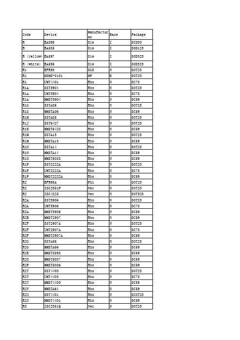
Nec Rho Rho Tfk Nec HP SGS Nec Nec Nec Nec HP Phi Sie Nec Nec Nec Nec Nec Nec Nec Nec Nec Nec Nec Nec Nec Nec Nec Nec Nec Nec Nec Nec Nec Nec Nec Nec Nec Nec Nec Nec Nec Nec Nec Nec Nec
Nec Nec Nec Nec Nec Nec Nec Nec Nec Nec Nec Nec Rho Sie Sie Rho Rho Rho Rho Mot Sie Sie Sie Sie Sie Sie Sie Sie Sie Sie Sie Sie Sie Sie Sie Nec Sie Sie Sie Sie Nec Rho Sie Sie Sie Sie Sie
RGs RHs RHs RHs RHs RHs RH RHs RIs RKs RKs RKM RK RR RR RVZ RW RZC RZC
BFS482 BFR183 BFR183W BFR183T BFP183 BFP183W 2SC3357 BFS483 BFP196 BFP194 BFR194 RK7002 2SC3357 BBY59-02V BFR93P MMST4126 BFR194 SST4124 MMST4124
N N N R WQ S R WQ N N N RQ N TQ WQ N N N N N N N WQ WQ WQ WQ WQ WQ N N N N N N N WQ WQ WQ WQ WQ WQ N N N N N N
SOT323 SOT23 SC59 SOT143 SOT143 SOT23R SOT143 SOT323 SOT323 SOT323 SOT145 SOT23 SOT143 SOT143 SOT23 SOT23 SOT323 SOT23 SOT323 SOT23 SOT323 SOT143 SOT343 SOT143 SOT343 SOT143 SOT343 SOT23 SOT23 SOT323 SOT23 SOT323 SOT23 SOT323 SOT143 SOT343 SOT143 SOT343 SOT143 SOT343 SOT23 SOT23 SOT323 SOT23 SOT323 SOT23
美嘉图电子显微镜产品目录说明书
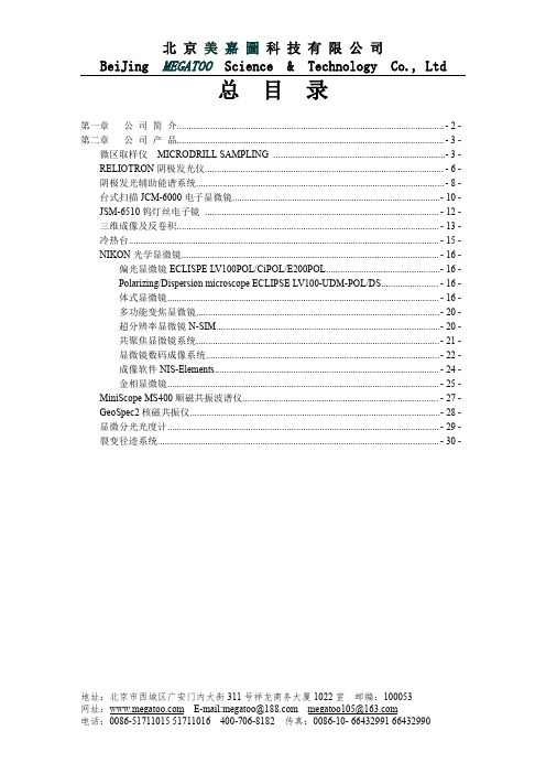
总目录第一章公司简介 (2)第二章公司产品 (3)微区取样仪MICRODRILL SAMPLING (3)RELIOTRON阴极发光仪 (6)阴极发光辅助能谱系统 (8)台式扫描JCM-6000电子显微镜 (10)JSM-6510钨灯丝电子镜 (12)三维成像及反卷积 (13)冷热台 (15)NIKON光学显微镜 (16)偏光显微镜ECLISPE LV100POL/CiPOL/E200POL (16)Polarizing/Dispersion microscope ECLIPSE LV100-UDM-POL/DS (16)体式显微镜 (16)多功能变焦显微镜 (20)超分辨率显微镜N-SIM (20)共聚焦显微镜系统 (21)显微镜数码成像系统 (22)成像软件NIS-Elements (24)金相显微镜 (25)MiniScope MS400顺磁共振波谱仪 (27)GeoSpec2核磁共振仪 (28)显微分光光度计 (29)裂变径迹系统 (30)地址:北京市西城区广安门内大街311号祥龙商务大厦1022室邮编:100053第一章公司简介北京美嘉图科技有限公司是一家以科技创新为主,具有高新技术根基的专业公司,是欧洲、美国、日本等多家厂商的仪器、仪表生产商在中国大陆地区的代理。
主要从事地质、石油、化工、生物等行业区域内的专业分析仪器、光学仪器仪表,并负责安装调试及售后技术服务;同时,还是一家为石油石化企业供应石油设备,石油生产物资的诚信供应商,本公司在石油工程技术服务领域也有着成熟的技术和优秀的管理及销售技术团队。
公司所代理的产品均具有世界先进水平,大部分为世界顶级品牌。
所代理的产品、设备已广泛应用于各著名大学、研究单位、石油化工生产及检验领域、检疫、商检和政府机构等,客户网络包括许多国内外知名企业及跨国大公司。
公司提供的石油物资也是国内外品牌的产品,在石油工程技术服务方面,本着科技领先的理念,不断探索与创新,打造了一支高素质的技术服务团队。
TC-412完全中文说明书

删除键是用来在程序编辑的时候删除某一步骤或者循环的。
在程序编辑的时候暂停键是在一个循环结束后用来插入暂停,或者用来插入递增或者递减温度和时间的。当程序运行的时候它也可以用来暂停程序。
开机
当你开机的时候,你就会看见与此图相似的开机页面。此屏会出现很短的时间,随后下一个屏幕将会自动出现。如果你想确认热块的型号和软件的版本,你可以在下一屏进入信息区域“Information”。
在提示行此符号代表的意义等同于结束键“End”
在提示行此符号的意思是此程序已经被锁住;它可以被拷贝,然后进行编辑但是不能直接编辑
底部那一行可以改变,或者此行内两个或者三个不同的提示符都闪动,这取决于上部那一行是发光的。此图是底部三个不同的提示符同时闪动的例子。
指示器
电源:此指示灯在TC-412接上电源后会闪亮。
状态:此指示灯在TC-412运行程序的时候会闪亮。当仪器停止的时候会关闭。当程序暂停的时候它会闪光并且缓慢的发出嘟嘟声。当仪器达到最终保持温度的时候,5秒后它会闪动并且发出急促的嘟嘟声。
但是,有时候实际应用电压可能发生变化,电压也没有必要满足两端极限。
运行条件
TC-412在下面
湿度 最高可达95%的湿度范围,外界没有冷凝现象
注意:此处引用的控制规范是在外界环境温度为20℃条件下。
在环境温度超出18℃到30℃范围后,可能对机器造成一定的损害。
电波频率干扰测试达到EN50081-1标准。
免疫性测试达到EN50082-1标准。
TC-412
TC-412有很多的科学实验室应用功能,包括DNA的测序和PCR反应。PCR反应在美国已经获得了专利,专利号为Nos.,和。使用TC-412进行PCR反应不需要获得此程序的认可。
ESP-07S规格书说明书

ESP-07S规格书版本V1.0版权©2019免责申明和版权公告本文中的信息,包括供参考的URL地址,如有变更,恕不另行通知。
文档“按现状”提供,不负任何担保责任,包括对适销性、适用于特定用途或非侵权性的任何担保,和任何提案、规格或样品在他处提到的任何担保。
本文档不负任何责任,包括使用本文档内信息产生的侵犯任何专利权行为的责任。
本文档在此未以禁止反言或其他方式授予任何知识产权使用许可,不管是明示许可还是暗示许可。
文中所得测试数据均为安信可实验室测试所得,实际结果可能略有差异。
Wi-Fi联盟成员标志归Wi-Fi联盟所有。
文中提到的所有商标名称、商标和注册商标均属其各自所有者的财产,特此声明。
最终解释权归深圳市安信可科技有限公司所有。
注意由于产品版本升级或其他原因,本手册内容有可能变更。
深圳市安信可科技有限公司保留在没有任何通知或者提示的情况下对本手册的内容进行修改的权利。
本手册仅作为使用指导,深圳市安信可科技有限公司尽全力在本手册中提供准确的信息,但是深圳市安信可科技有限公司并不确保手册内容完全没有错误,本手册中的所有陈述、信息和建议也不构成任何明示或暗示的担保。
文件制定/修订/废止履历表版本日期制定/修订内容制定核准V0.92016.03.04首次制定杨小飞V1.02019.10.29资料更新谢一骥目录一、产品概述 (5)二、电气参数 (8)三、外观尺寸 (10)四、管脚定义 (11)五、原理图 (12)六、设计指导 (13)七、回流焊曲线图 (15)八、包装信息 (16)九、联系我们 (16)一、产品概述ESP-07S是由安信可科技开发的Wi-Fi模块,该模块核心处理器ESP8266在较小尺寸封装中集成了业界领先的Tensilica L106超低功耗32位微型MCU,带有16位精简模式,主频支持80MHz和160MHz,支持RTOS,集成Wi-Fi MAC/BB/RF/PA/LNA。
(整理)MMS6120用户手册

第一章MMS 6120 轴承振动监测模块一. 模块工作原理及功能MMS6120是双通道轴承振动测量模块,其工作原理见图1,接线图见图3至图5。
1. 信号输入MMS6120有两路独立的电动式速度传感器信号输入—SENS 1H(z8)/SENS 1L(z10)和SENS 2H(d8)/SENS 2L(d10)。
与之匹配的速度传感器为德国epro公司生产的PR926X 系列电动式传感器,输入电压范围为-5…+15 V dc 。
模块为每个传感器提供一个0…8mA的提升线圈电流,可补偿传感器线圈的机械沉降,此补偿电流在组态中可选:SENS 1+(z6)/SENS 1-(b6)和SENS 2+(d6)/SENS2-(b8)。
传感器信号可以在模块前面板上SMB接口处测到。
此外模块还备有键相信号输入(必须大于13V),该信号是速度控制方式及频谱分析所必需的。
2. 信号输出a. 特征值输出模块有两路代表特征值的电流输出:I1+(z18)/ I1-(b18)和I2+(z20)/ I2-(b20),可设定为0…20mA或4…20mA。
模块有两路代表特征值的0…10 V电压输出EO 1(d14)/ EO 2(d16)。
b. 动态信号输出模块提供两路0…20 Vpp动态信号输出AC1(z14)/ AC2(z16)用于频谱分析。
0…20 Vpp相当于特征值的量程。
限值监测a. 报警值每个通道可以分别设定报警值和危险值。
报警开关特性为测量值上升时超限触发。
为避免测量值在限值附近的变化反复触发报警,可设置报警滞后值,在满量程的1…10%之间选择,特性为下降触发。
b. 限值倍增器及倍增系数X在特殊情况下,如过临界转速时,振动幅值会很大,乃至超限,但此时机组处于正常运行状态。
为避免不必要的报警或跳机,可在软件中激活限值倍增器功能,并设置倍增系数X(1.00~5.00)提高报警值。
使用此功能时,d18应为低电平。
倍增系数X同时影响报警值和危险值。
K-9可选配件,微维克斯硬度试验机剪子订单号型号及描述说明书
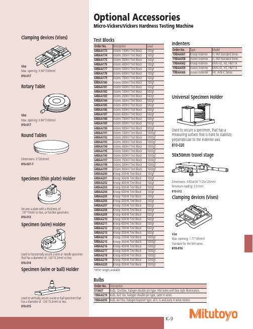
G
steel ball 1471N(150kgf) beryllium copper, phosphor bronze
H
1/8”
588.4N(60kgf) Bearing metal
E
diameter 980.7N(100kgf)
K
steel ball 1471N(150kgf)
L
1/4”
588.4N(60kgf) Plastics, lead
50x50mm travel stage
Dimensions: 4.92x4.92”(125x125mm) Minimum reading: 0.01mm 810-012
Clamping devices (Vises)
Vise Max. opening: 1.77”(45mm) Standard for the MH series. 810-016
Indenters
Order No. 19BAA061 19BAA058 19BAA062 19BAA059 19BAA060
Type Knoop Indenter Vickers Indenter Knoop Indenter Vickers Indenter Vickers Indenter
Model H, HM Standard Series H, HM Standard Series MVK-H2, H3, HM114 MVK-H2, H3, HM114 HV, AVK-C Series
Micro-Vickers/Vickers Hardness Testing Machine
Test Blocks
Order No. 64BAA173 64BAA174 64BAA175 64BAA176 64BAA177 64BAA178 64BAA179 64BAA180 64BAA181 64BAA182 64BAA183 64BAA184 64BAA185 64BAA186 64BAA187 64BAA188 64BAA189 64BAA190 64BAA191 64BAA192 64BAA193 64BAA194 64BAA195 64BAA196 64BAA197 64BAA198 64BAA199 64BAA200 64BAA201 64BAA202 64BAA203 64BAA204 64BAA205 64BAA206 64BAA207 64BAA208 64BAA209 64BAA210 64BAA211 64BAA212 64BAA213 64BAA214 64BAA215 64BAA216 64BAA217 64BAA218 64BAA219 64BAA220
MP902技术规格书

MP902产品技术规范版本V ersion:V1.00发布日期Date:18/4/2008文件编号Document Number:xxxx深圳梦网科技发展有限公司本文档适用的产品是MP902彩信监控器。
本文档以MP902产品为例,主要介绍MP902产品的外观、硬件结构、功能、技术规格和模块有关指标的测试标准,用于帮助市场技术支持工程师提供技术支持及测试人员测试提供参考。
阅读对象本文档主要适用于以下工程师:产品工程师市场技术支持工程师测试工程师修改记录修订记录累积了每次文档更新的说明。
最新版本的文档包含以前所有文档版本的更新内容。
文档版本V1.0 (2008-04-18)第一次正式发布。
目录1 产品简介 (1)2 缩略语 (1)3外观和结构 (2)4功能 (3)4.1主要功能定义 (3)5主要技术规格 (4)5.1通讯协议及技术指标 (4)5.2射频接收 (4)5.3遥控接收 (4)5.4天线 (4)5.5主要性能指标 (5)5.6待机时间 (5)5.7工作条件 (5)6可靠性测试标准 (6)6.1跌落实验 (6)6.2振动实验 (6)6.3低温运行实验 (6)6.4低温存储实验 (7)6.5高温运行实验 (7)6.6高温存储实验 (7)6.7高温高湿实验 (8)6.8高低温冲击实验 (8)7 EMC/EMI测试标准 (8)7.1静电放电试验(ESD) (8)7.2射频电磁场辐射抗扰性试验 (9)7.3电快速瞬变脉冲群抗扰性试验 (9)7.4雷击浪涌抗扰性试验 (10)7.5射频电磁场传导抗扰性试验 (10)7.6电压瞬时跌落和短时中断的抗扰性试验 (11)7.7辐射发射试验 (11)8引用标准 (11)9产品齐套 (12)1产品简介深圳梦网科技发展有限公司是一家生产GSM/CDMA无线终端产品的国内知名企业,是国内最早开发和批量生产GSM、CDMA无线终端产品的厂商,拥有多年的研发与生产经验。
V90-B1.1彩信监控器是利用图像移动侦测和被动红外人体感应技术,将监控现场的异常用摄像头拍摄下来,经图像压缩,再经GSM模块通过移动通信网的彩信服务、GPRS功能,将现场拍摄到的画面传输到指定用户手机、邮箱或互联网管理平台的无线监控设备。
Meggitt SA IPC704信号条件器说明说明书
© Meggitt SA / 262-710 / Version 12 / 08.11.2017 / E 1 / 16Information contained in this document may be subject to Export Control Regulations of the European Union, USA or other countries. Each recipient of this document is responsible for ensuring that transfer or use of any information contained in this document complies with all relevant Export ControlRegulations. ECN N/A.IPC704Signal conditionerFEATURES»From the Vibro-Meter ® product line »For CAxxx piezoelectric accelerometers and CPxxx dynamic pressure sensors »Configurable high-pass and low-pass filters »Frequency range: 0.5 Hz to 20 kHz»Optional integrator to produce a velocity output »Optional 2-wire current or 3-wire voltage transmission»Certified for use in potentially explosive atmospheres»A range of installation options are availableIPC704IECEx NEPSI KGSDESCRIPTIONThe IPC704 signal conditioner converts the charge-based signal from a piezoelectric-based transducer into a current or a voltage signal. This current or volt-age signal is transmitted to the processing electronics via a standard 2-wire or 3-wire transmission cable. The current modulation technique allows transmis-sion over a distance of up to 1 km. A GSI galvanic separation unit is required for this configuration.The electronic circuitry of the IPC704 signal condi-tioner is incorporated into a moulded aluminium enclosure. The signal conditioner has configurablehigh-pass and low-pass filters and an optional inte-grator to give a velocity output. Furthermore, RFI fil-ters protect the input and output against radio-frequency interference and other electromagnetic influences.A range of installation options are available for the IPC704 signal conditioner, including:» A polyester enclosure providing environmental protection against dust, oil and water jets.»A mounting adaptor allowing the IPC704 signal conditioner to be mounted on a DIN rail.Signal conditioner IPC7042 / 16© Meggitt SA / 262-710 / Version 12 / 08.11.2017 / EDESCRIPTION (continued)Two versions of the IPC704 signal conditioner are available:»An IPC704 for sensors using standard piezoelectric materials, for example, CAxxx,CP10x and CP2xx(ordering number 244-704-000-042-... ).»An IPC704 for sensors using GaPO4 piezoelectric material, for example, CP50x (ordering number 244-704-000-511-... ).BLOCK DIAGRAM(electrically c onductive)COM O/P +24VSPECIFICATIONSEnvironmental characteristics(Specifications according to IEC 60068-2 recommendations)GeneralTemperature•Operation:−30 to +85 °C•Storage:−40 to +85 °CHumidity:Max. 95 % non-condensing.Note: For operation in a humid environment, ordering option A3 (pottedversion) should be considered.Protection rating(according to IEC 60529):IP40Vibration(according to IEC 60068-2-26):2 g peak between 10 and 500 HzShock acceleration(according to IEC 60068-2-27):15 g peak (half sine, 11 ms duration)Industrial housing (ordering option G1)Protection rating(according to IEC 60529):IP66Impact resistance:> 4mJ/mm2 (DIN 53453)Chemical resistance:Good resistance to seawater, acids, alkaline solutions, gasoline and oils Flammability:UL94V-0 self-extinguishing© Meggitt SA / 262-710 / Version 12 / 08.11.2017 / E3 / 16Signal conditionerIPC704Explosive atmospheresAvailable in Ex approved versions for use in hazardous locationsType of protection Ex i: intrinsic safety (ordering option A2)EuropeEC type examination certificate LCIE 02 ATEX 6085 XII 2G (Zones 1, 2)Ex ib IIC T6 … T4 GbNorth AmericaC CSAUS certificate C CSA US 1243981Class I, Division 1, Groups A, B, C, DEx ia (T6 to T4)International IECEx certificate of conformity IECEx LCI 06.0009XEx ib IIC T6 … T4 GbChina NEPSI certificate of conformity*GYJ12.1450XEx ib IIC T6 to T4 GbKoreaKGS certificate of conformity 12-GA4BO-0396XEx ib IIC T6 to T4Type of protection Ex nA: non-sparking (ordering option A3)EuropeVoluntary type examination certificate LCIE 09 ATEX 1027 XII 3G (Zone 2)Ex nA IIC T6 … T5 GcNorth AmericaC CSA US certificate C CSA US 1243981Class I, Division 2, Groups A, B, C, D Ex nA IIC T6 to T5 Gc Class I, Zone 2AEx nA IIC T6 to T5 GcInternationalIECEx certificate of conformity IECEx LCIE 13.0053XEx nA IIC T6 … T5 Gc* N ot engraved on the product marking.For specific parameters of the mode of protection concerned and special conditions for safe use, refer to the certificates that are available from Meggitt SA on demand.When using protection mode ‘nA’ (non-sparking apparatus), the user shall ensure that the signalconditioner is installed in an enclosure that ensures a protection rating of at least IP54 (or equivalent).For the most recent information on the Ex certifications that are applicable to this product, refer to the Ex product register (PL-1511) document that is available from Meggitt SA.Industrial housing (ordering option G1)Available in Ex approved versions for use in hazardous locations•Environment:II 2 G (Zones 1, 2) Ex e II < 109Ω (DIN 53482)•Surface resistivity for Ex version:Stuffing glandsAvailable in Ex approved versions for use in hazardous locations•Environment:II 2 G/D (Zones 1, 2) Ex e II For specific parameters of the mode of protection concerned and special conditions for safe use,refer to the certificates that are available from Meggitt SA on demand.For the most recent information on the Ex certifications that are applicable to this product, refer to the Ex product register (PL-1511) document that is available from Meggitt SA.SPECIFICATIONS (continued)Signal conditioner IPC7044 / 16© Meggitt SA / 262-710 / Version 12 / 08.11.2017 / EPower supply to IPC704Voltage :18 to 30 V DC Current:25 mA (max.)Transfer characteristics (ordering option B)IPC704 for sensors using standard piezoelectric materials (244-704-000-042-... )•Transfer without integrator:0.1 to 10 mV/pC or 0.1 to 10 µA/pC •Transfer with integrator:981 to 98 100 mV/(pC.s) or 981 to 98 100 µA/(pC.s)IPC704 for sensors using GaPO 4 piezoelectric material (244-704-000-511-... )•Transfer:0.1 to 50 mV/pC or 0.1 to 50 µA/pC Linearity error:≤ 0.2 %Temperature stability :100 ppm / °C typicalPhase:180° between the input signal and the acceleration output.180° between the input signal and the pressure output. 90° between the acceleration and velocity outputs.See the graph below.Input characteristics (ordering option C)Compatible sensors:Any piezoelectric-based transducer – symmetrical or non-symmetrical, case grounded or insulated Dynamic range:100 000 pC peak Input sensitivity•Accelerometers:See IPC704 for accelerometers (acceleration output) using standard piezoelectric materials on page 6 andIPC704 for accelerometers (velocity output) using standard piezoelectric materials on page 6•Dynamic pressure transducers:See IPC704 for pressure sensors using standard piezoelectric materials on page 7 andIPC704 for pressure sensors using GaPO4 piezoelectric material on page 8Charge amplifier:Symmetrical RFI filter:Symmetrical LC network Resistance:≥ 50 k Ω (sensor and cable)Capacitance:≤ 10 nF (sensor and cable)SPECIFICATIONS(continued)Input signalAcceleration and pressureVelocity At© Meggitt SA / 262-710 / Version 12 / 08.11.2017 / E 5 / 16Signal conditionerIPC704Output characteristics (ordering option D)RFI filter:Symmetrical LC network 2-wire current transmission•Dynamic signal:Max. ± 5 mA peak •Standing current :12 mA ± 0.5 mA•Electrical connection:+24 V = “+”, COM = “−”•Output sensitivity:See Ordering information on page 12•Max. dynamic range:5 mA peak / o utput sensitivity 3-wire voltage transmission•Dynamic signal :Max. ± 5 V peak •Standing voltage :7.5 V ± 0.2 V•Output sensitivity:See Ordering information on page 12•Output impedance:750 Ω (3-wire configuration)•Max. dynamic range :5 V peak / o utput sensitivityThe 3-wire voltage output without galvanic separation unit should only be used with piezoelectric-basedtransducers which are insensitive to frame voltage.Dynamic pressure transducers should always be used with a GSI galvanic separation unit .Filter characteristics (ordering options E and F)High-pass filter•Cutoff frequencies (at −3 dB):0.5, 1, 2, 5 or 10 Hz (all ± 20 %)•Slope:24 dB/octave (4th order)When selecting a high-pass filter, be careful to select an appropriate frequency for the charge amplifier. See the charge amplifier frequencies versus transfer unit graphs on the following pages.Low-pass filter•Cutoff frequencies (at −1 dB):200, 500, 1 000, 2 000, 5 000, 10 000 or 20 000 Hz (all ± 10 %)•Slope:12 dB/octave (2nd order)SPECIFICATIONS(continued)Signal conditioner IPC7046 / 16© Meggitt SA / 262-710 / Version 12 / 08.11.2017 / ECharge amplifier frequencies versus transfer unitIPC704 for accelerometers (acceleration output) using standard piezoelectric materialsIPC704 for accelerometers (velocity output) using standard piezoelectric materialsSPECIFICATIONS (continued)Output sensitivity (mV/ g or µA / g )T r a n s d u c e r s e n s i t i v i t y (p C / g )1001NotesFor operation in different regions of the chart, the cutoff frequency of the IPC704’s charge amplifier dictates the required high-pass filter settings. (See the HP FILTER (E) option in ordering information.)Region 1: Cutoff frequency is 0.5 Hz → HP filter ≥0.5 Hz.Region 2: Cutoff frequency is 1 Hz → HP filter ≥1Hz.Region 3: Cutoff frequency is 2 Hz → HP filter ≥2Hz.Region 4: Cutoff frequency is 3 Hz → HP filter ≥5Hz.200100502010521502010Ordering number 244-704-000-042-... with ordering options B01 and B02T r a n s d u c e r s e n s i t i v i t y (p C / g )1001502010Output sensitivity (mV/ m m/s or µA / m m/s)1005020105210.5Output sensitivity (mV/ i ps or µA / i ps)2540127050825412750.825.412.7Ordering number 244-704-000-042-... with ordering options B03, B04, B05 and B06NotesFor operation in different regions of the chart, the cutoff frequency of the IPC704’s charge amplifier dictates the required high-pass filter settings. (See the HP FILTER (E) option in ordering information.)Region 1: Cutoff frequency is 0.5 Hz → HP filter ≥0.5 Hz.Region 2: Cutoff frequency is 1 Hz → HP filter ≥1Hz.Region 3: Cutoff frequency is 2 Hz → HP filter ≥2Hz.Region 4: Cutoff frequency is 3 Hz → HP filter ≥5Hz.© Meggitt SA / 262-710 / Version 12 / 08.11.2017 / E 7 / 16Signal conditionerIPC704IPC704 for pressure sensors using standard piezoelectric materialsSPECIFICATIONS (continued)Output sensitivity (mV/ m bar or µA / m bar)T r a n s d u c e r s e n s i t i v i t y (p C /b a r )95010750250190Output sensitivity (mV/ p si or µA / p si)25T r a n s d u c e r s e n s i t i v i t y (p C / p s i )NotesFor operation in different regions of the chart, the cutoff frequency of the IPC704’s charge amplifier dictates the required high-pass filter settings. (See the HP FILTER (E) option in ordering information.)Region 1: Cutoff frequency is 0.5 Hz → HP filter ≥0.5 Hz.Region 2: Cutoff frequency is 1 Hz → HP filter ≥1Hz.Region 3: Cutoff frequency is 2 Hz → HP filter ≥2Hz.Region 4: Cutoff frequency is 3 Hz → HP filter ≥5Hz.Ordering number 244-704-000-042-... with ordering options B07, B08, B09 and B10Signal conditioner IPC7048 / 16© Meggitt SA / 262-710 / Version 12 / 08.11.2017 / EIPC704 for pressure sensors using GaPO 4 piezoelectric materialSPECIFICATIONS (continued)Output sensitivity (mV/ m bar or µA / m bar)T r a n s d u c e r s e n s i t i v i t y (p C / p s i )T r a n s d u c e r s e n s i t i v i t y (p C / b a r )Output sensitivity (mV/ p si or µA / p si)NotesFor operation in different regions of the chart, the cutoff frequency of the IPC704’s charge amplifier dictates the required high-pass filter settings. (See the HP FILTER (E) option in ordering information.)Region 1: Cutoff frequency is 0.5 Hz → HP filter ≥0.5 Hz.Region 2: Cutoff frequency is 1 Hz → HP filter ≥1Hz.Ordering number 244-704-000-511-... with ordering options B07, B08, B09 and B10Signal conditionerIPC704Physical characteristicsSignal conditioner without industrial housing (ordering option G0)•Enclosure:Injection moulded aluminium, anodized•Mounting:Two or four M4 screws•Weight:Standard version: 170 gEx version: 250 g (the signal conditioner is moulded into silicon)•Dimensions:See Mechanical drawings on page 10•Electrical connection (input):Three screw terminals – wire section 2.5 mm2 (max.)•Electrical connection (output):Three screw terminals – wire section 2.5 mm2 (max.)Signal conditioner with industrial housing (ordering option G1)•Enclosure:Polyester reinforced with glass fibre•Cover seal:Silicone gasket•Mounting:M6 x 30 mm Allen screws•Dimensions:See Mechanical drawings on page 10Input/output stuffing glands (ordering options H and I)•Type:See Ordering information on page 12•Material:Nickel-plated brass with Viton® sealSignal conditioner with MA130 mounting adaptor (ordering option G2)Universal DIN rail holder type:TSH 35DIN rail type(according to EN 50022 / IEC 60715):TH 35-7.5 or TH 35-15SPECIFICATIONS (continued)© Meggitt SA / 262-710 / Version 12 / 08.11.2017 / E9 / 16Signal conditioner IPC70410 / 16© Meggitt SA / 262-710 / Version 12 / 08.11.2017 / EMECHANICAL DRAWINGSSignal conditionerIPC704MECHANICAL DRAWINGS (continued)Signal conditioner IPC704ORDERING INFORMATIONIPC704 signal conditioner for sensors using standard piezoelectric materials Ordering number: 244 - 704 - 000 - 042ENVIRONMENT (A)Standard 1Explosive Ex i 2Explosive Ex nA3TRANSFER UNIT (B)INPUT OUTPUT pC/g µA/g 01pC/g mV/g 02pC/g µA /m m/s 03pC/g mV/ m m/s 04pC/g µA /i n/s 05pC/g mV/ i n/s 06pC/bar µA/mbar 07pC/bar mV/mbar 08pC/psi µA/psi 09pC/psimV/psi10OUTPUT CABLE FITTING (I)No cable fitting (no hole)0M16 x 1.5 with plug1Cable gland M16 x 1.5 for cable Ø4 - Ø7 mm 3Cable gland M16 x 1.5 for cable Ø7 - Ø11 mm 4Adaptor M16 x 1.5 / PG9 with plug 8Adaptor M16 x 1.5 / M20 x 1.5 with plug10B A D E F G H IC INPUT SENSITIVITY (C)Sensor sensitivityOUTPUT SENSITIVITY (D)Value per mechanical unitLP FILTER (F)Value in HzHP FILTER (E)Value in HzINPUT CABLE FITTING (H)No cable fitting (no hole)0M16 x 1.5 with plug1Cable gland M16 x 1.5 for cable Ø4 - Ø7 mm 3Cable gland M16 x 1.5 for cable Ø7 - Ø11 mm 4Adaptor M16 x 1.5 / PG9 with plug 8Adaptor M16 x 1.5 / M20 x 1.5 with plug10INSTALLATION (G)Signal conditioner only0Signal conditioner with industrial housing 1Signal conditioner assembled on MA130 mounting adaptor2Low-pass filter200 Hz 500 Hz 1 000 Hz 2 000 Hz 5 000 Hz 10 000 Hz 20 000 HzHigh-pass filter0.5 Hz 1 Hz 2 Hz 5 Hz 10 Hz(2)(2)(1)Notes1. With options A3 and G0 / G 2, the user shall ensure that the signal conditioner is installed in an enclosure that ensures a protection rating of at least IP54 (or equivalent).2. With option H0, only option I0 is available.Signal conditionerIPC704IPC704 signal conditioner for sensors using GaPO 4 piezoelectric material ORDERING INFORMATION (continued)Ordering number: 244 - 704 - 000 - 511ENVIRONMENT (A)Standard 1Explosive Ex i 2Explosive Ex nA3TRANSFER UNIT (B)INPUT OUTPUT pC/bar µA/mbar 07pC/bar mV/mbar 08pC/psi µA/psi 09pC/psimV/psi10OUTPUT CABLE FITTING (I)No cable fitting (no hole)0M16 x 1.5 with plug1Cable gland M16 x 1.5 for cable Ø4 - Ø7 mm 3Cable gland M16 x 1.5 for cable Ø7 - Ø11 mm 4Adaptor M16 x 1.5 / PG9 with plug 8Adaptor M16 x 1.5 / M20 x 1.5 with plug10B A D E F G H IC INPUT SENSITIVITY (C)Sensor sensitivityOUTPUT SENSITIVITY (D)Value per mechanical unitLP FILTER (F)Value in HzHP FILTER (E)Value in HzINPUT CABLE FITTING (H)No cable fitting (no hole)0M16 x 1.5 with plug1Cable gland M16 x 1.5 for cable Ø4 - Ø7 mm 3Cable gland M16 x 1.5 for cable Ø7 - Ø11 mm 4Adaptor M16 x 1.5 / PG9 with plug 8Adaptor M16 x 1.5 / M20 x 1.5 with plug10INSTALLATION (G)Signal conditioner only0Signal conditioner with industrial housing 1Signal conditioner assembled on MA130 mounting adaptor2Low-pass filter200 Hz 500 Hz 1 000 Hz 2 000 Hz 5 000 Hz 10 000 Hz 20 000 HzHigh-pass filter0.5 Hz 1 Hz 2 Hz 5 Hz 10 Hz(2)(2)(1)Notes1. With options A3 and G0 / G 2, the user shall ensure that the signal conditioner is installed in an enclosure that ensures a protection rating of at least IP54 (or equivalent).2. With option H0, only option I0 is available.Signal conditioner IPC704MOUNTING ACCESSORIESABA160 industrial housingNotes1. Suitable for potentially explosive atmospheres only when used with Ex i certified products from Meggitt Sensing Systems’ Vibro-Meter p roduct line. A ll machining on the industrial housing must comply with the operational manual of the housing manufacturer.2. With option B00, only option C00 is available.Ordering number: 830 - 160 - 000 - 111ENVIRONMENT (A)Standard polyester 1Explosive Ex i2CABLE FITTING INPUT (B)No cable fitting (no hole)00M16 x 1.5 with plug01Cable gland M16 x 1.5 for cable Ø4 - Ø7 mm 03Cable gland M16 x 1.5 for cable Ø7 - Ø11 mm 04Adaptor M16 x 1.5 / PG9 with plug 08Adaptor M16 x 1.5 / M20 x 1.5 with plug (cable Ø12 mm max.)10CABLE FITTING OUTPUT (C)No cable fitting (no hole)00M16 x 1.5 with plug01Cable gland M16 x 1.5 for cable Ø4 - Ø7 mm 03Cable gland M16 x 1.5 for cable Ø7 - Ø11 mm 04Adaptor M16 x 1.5 / PG9 with plug 08Adaptor M16 x 1.5 / M20 x 1.5 with plug (cable Ø12 mm max.)10A B1C1(2)(2)(1)Signal conditionerIPC704MA130 mounting adaptorOrdering number: 809-130-000-011Base plate for IPC704 signal conditionerThis aluminium base plate can be used when an old IPC620 unit is replaced by an IPC704 signal conditioner. The housing of the IPC620 can be reused and the IPC704 mounted on it.Ordering number: 244-620-002S034MOUNTING ACCESSORIES (continued)Note: All dimensions in mm unless otherwise stated.R 49123054~ R 2~ R 24.53970139Ø5, 5H 114.527454.5130148Note: All dimensions in mm unless otherwise stated.Signal conditionerIPC704Headquartered in the UK, Meggitt PLC is a global engineering group specializing in extreme environment components and smart sub-systems for aerospace, defence and energy markets.Meggitt Sensing Systems is the operating division of Meggitt specializing in sensing and monitoring systems, which has operated through its antecedents since 1927 under the names of ECET, Endevco, Ferroperm Piezoceramics, Lodge Ignition, Sensorex and Vibro-Meter. Today, these operations are integrated under one strategic business unit called Meggitt Sensing Systems, headquartered in Switzerland and providing complete systems, using these renowned brands, from a single supply base.The Meggitt Sensing Systems facility in Fribourg, Switzerland was formerly known as Vibro-Meter SA, but is now Meggitt SA. This site produces a wide range of vibration and dynamic pressure sensors capable of operation in extreme environments, leading-edge microwave sensors, electronics monitoring systems and innovative software for aerospace and land-based turbo-machinery.All statements, technical information, drawings, performance rates and descriptions in this document, whilst stated in good faith, are issued for the sole purpose of giving an approximate indication of the products described in them, and are not binding on Meggitt SA (Meggitt Sensing Systems) unless expressly agreed in writing. Before acquiring this product, you must evaluate it and determine if it is suitable for your intended application. You should also check our website at /energy for any updates to data sheets, Ex certificates, product drawings, user manuals, service bulletins and/or other instructions affecting the product. Unless otherwise expressly agreed in writing with Meggitt SA, you assume all risks and liability associated with use of the product. Any recommendations and advice given without charge, whilst given in good faith, are not binding on Meggitt SA.Meggitt SA (Meggitt Sensing Systems) takes no responsibility for any statements related to the product which are not contained in a current Meggitt Sensing Systems publication, nor for any statements contained in extracts, summaries, translations or any other documents not authored and produced by Meggitt SA. Meggitt SA reserves the right to alter any part of this publication without prior notice.In this publication, a dot (.) is used as the decimal separator and thousands are separated by thin spaces. Example: 12 345.678 90.Sales offices Your local agent Head officeMeggitt Sensing Systems has offices in more than 30 countries. For a complete list, please visit our website.Meggitt SARoute de Moncor 4PO Box 16161701 FribourgSwitzerlandTel: +41 26 407 11 11Fax: +41 26 407 13 01*****************.com /energyISO 9001FS 584089。
Fanconn 4G 全网通摄像头通信模块说明书
Fanconn4G全⽹通摄像头通信模块说明书敬告:本文档版权归内容原创公司所有,并保留一切权力。
文档内容如有修改更新,请联系提供方获取最新版本,恕不另行通知。
Note: This document is copyrighted by the content original company and all rights reserved. If the contents of the document are updated, please contact the provider for the latest version without notice.修改记录Changelog目录Contents1.主芯片简介EC20 (4)2.产品概述PRODUCT OVERVIEW (5)3.规格清单SPECIFICATION LIST (6)4.接口定义 INTERFACE DEFINITION (8)5.物理尺寸PHYSICAL SIZE (9)1.主芯片简介EC20EC20 R2.1 是移远通信最近推出的LTE Cat 4 无线通信模块,采用LTE 3GPP Rel.11 技术,支持最大下行速率150Mbps 和最大上行速率50Mbps ;同时在封装上兼容移远通信UMTS/HSPA+ UC20 模块以及移远通信多网络制式LTE Cat 3 模块,实现了3G 网络与4G 网络之间的无缝切换。
频段:LTE FDD: B1/B3/B5/B8LTE TDD: B34/B38/B39/B40/B41WCDMA: B1/B8TD-SCDMA: B34/B39CDMA: BC0GSM: 900/1800MHz,EC20数据传输速度快,支持多种方式:LTE、UTMS、TD-SCDMA、CDMA2000、EVDO、GSM、EDGE。
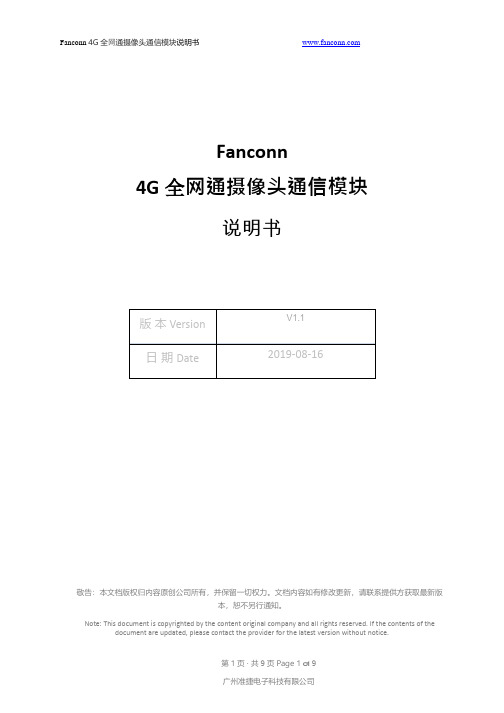
4G全⽹通摄像头通信模块主要优势:(1)模块采⽤的是⾼通全⽹通的⽅案,有多国版本可选择(2)产品主要用于IP摄像机(或者叫网络摄像机),一般安装在网络相机的内部(3)主板符合摄像机行业主板堆叠定位孔设计为38x38规格设计(4)支持集成多星座GNSS 接收机,满足不同环境下对快速、精准定位的需求(5)支持MIMO 技术满足无线通信系统对数据速率和连接可靠性的要求2.产品概述Product Overview4G全⽹通摄像头通信模块实物照片接口示意图如下所示。
412FM;中文规格书,Datasheet资料

DC axial compact fan
ebm-papst St. Georgen GmbH & Co. KG Hermann-Papst-Straße 1 D-78112 St. Georgen Phone +49 7724 81-0 Fax +49 7724 81-1309 info2@
/
分销商库存信息:
EBM-PAPST 412FM
Mass Dimensions Material of impeller Housing material Direction of air flow Direction of rotation Bearing Lifetime L10 at 20 °C Lifetime L10 at 60 °C Connection line Motor protection Approval
ml = max. load · me = max. efficiency · fa = running at free air · cs = customer specs · cu = customer unit Subject to alterations
Web data sheet XI · Page 1 of 4 ebm-papst St. Georgen GmbH & Co. KG · Hermann-Papst-Straße 1 · D-78112 St. Georgen · Phone +49 7724 81-0 · Fax +49 7724 81-1309 · info2@ ·
Web data sheet XI · Page 2 of 4 ebm-papst St. Georgen GmbH & Co. KG · Hermann-Papst-Straße 1 · D-78112 St. Georgen · Phone +49 7724 81-0 · Fax +49 7724 81-1309 · info2@ ·
快思聪产品品技术参数描述大全

快思聪产品技术参数描述触摸屏系列 (3)TPS-4L (3)TPS-6L (4)TPSI-6X (4)CT-1000的技术参数: (4)STI-1550C单向无线触摸屏: (4)CT-1550C有线触摸屏: (5)STI-1700C单向无线触摸屏: (5)STXI-1700CXP双向无线触摸屏: (5)STXI-1700CXP双向无线触摸屏: (5)TPS-1700C触摸屏: (6)TPS-2000L: (6)TPS-3000L: (6)TPMC-8L的技术参数: (7)TPS-3000: (7)TPS-4000的技术参数: (7)TPS-4000L的技术参数: (8)MiniTouch:MT-1000C (8)MiniTouch:ML-500无线紧凑式射频LCD远程遥控器 (8)MiniTouch:ML-600无线紧凑式射频LCD远程遥控器 (9)MLX-2:MiniLCD2路RF掌上遥控 (9)WPR-48 具有防水性能的遥控器 (9)TPS-12 (9)TPS-15 (10)TPS-17 (10)TPMC-CH-IMC 界面模块 (11)TPS-12G-QM (11)TPS-15-G-QM (11)TPMC-4XG Isys i/O™ WiFi 触摸屏: (12)TPMC-8X Isys i/O™ WiFi 触摸屏 (12)TPMC-8X-DS技术参数: (13)TPMC-15-QM Isys i/O™ 15” 触摸屏媒体中心 (13)TPMC-17-QM Isys i/O™ 17”触摸屏媒体中心 (15)控制主机系列 (16)MC2E的技术参数: (17)MC2W的技术参数: (17)CP2的技术参数: (17)CP2E的技术参数: (17)A V2的技术参数: (18)PRO2的技术参数: (18)MP2的技术参数: (18)MP2E的技术参数: (19)C2N-MMS的技术参数: (19)CNXRMC: (19)CNXRMCLV: (19)C2N-DVP4DI的技术参数: (20)DVPHD-PRO的技术参数: (20)MPS-100的技术参数: (21)MPS-300技术参数: (23)PAC2的技术参数: (24)PAC2M - Pro Mini 控制主机技术参数 (24)AADSI的技术参数: (25)AESI的技术参数: (25)AAE音频扩展器技术参数: (25)音频(AAS) 技术参数: (25)TPS-ENET的技术参数: (26)TPS-VID-1的技术参数: (26)TPS-VID-2: (26)TPS-XVGA的技术参数: (26)CNXRY-16的技术参数: (26)C2IR-8的技术参数: (27)C2COM-2的技术参数: (27)C2COM-3的技术参数: (27)C2ENET-1的技术参数: (27)C2ENET-2的技术参数: (27)C2VEQ-4 (27)常用扩展模块 (28)TPS-XTX-RF的技术参数: (28)CEN-TIA电话接口模块技术参数: (28)C2N-VEQ-4 (28)STI-COM的技术参数: (29)CNECI-4A的技术参数: (29)CLI-220N-4的技术参数: (29)CHAO-12模拟量控制模块 (29)SP-4的技术参数: (29)C2N-CAMIDSPT数字伺服式摄像机电动云台 (30)C2N-CAMIDJ操纵杆控制器 (31)CNRFGW A无线接收器 (31)CNRFGW-418无线接收器 (31)STRFGW A双向接收器 (32)TPS-RFGWXI (32)CEN-RFGW-ZB:ZigBee网关 (32)CENI-HPRFGW:高性能电源RF网关 (32)CLSI-C6A的技术参数: (33)C2N-SSC-2 (33)C2N-SDC-DC (33)CNX-B2...B12: .. (33)C2N-CB的技术参数: (34)APAD的技术参数: (34)CEN-IDOC Apple iPod®界面技术参数 (34)MediaManager (34)QM-RMC (35)QM-WMC: 墙面媒体终端 (35)QM-WMIC:墙面媒体终端 (36)QM-RMCRX: 主处理器 (36)QM-FTCC: 弹出式计算机界面 (36)QM-FTSC: 上翻式存储中心 (37)QM-FTDC:上翻式数据中心 (37)QM-MD8x8: QM切换矩阵 (37)QM-MD7x2: 快思聪矩阵 (38)QM-MD5X1 (38)QM-TX (39)QM-RX: QuickMedia 接收器 (39)QM-FTCC-TPS (39)QM-RX1-3G: (40)QM-TX2-MC (40)QM-TX2-CC (40)QM-WMC-CC (41)QM-WCC-2 (41)QM-WCC-1 (41)网络解决方案 (41)CEN-W AP-ABG-1G:802.11a/b/g无线接入点 (42)CEN-SW-POE-5: 5埠PoE切换器 (42)PW-4803RU:PoE电源供应器 (42)ADAD六路数字音频服务器 (42)快思聪优惠套装解决方案 (43)TPMC-10 Isys i/O 10” WiFi 平板式触摸屏 (44)QM-AMP3x80MM: 块思聪功放 (45)CNPI-48 48键控制面板接口 (46)IRP2 红外线发射器探头 (47)触摸屏系列TPS-4L● 3.6 英寸有源矩阵彩色触摸屏●32 位Coldfire® 处理器●320x240 象素●8 MB 闪存,16M DRAM●16 位Isys™ 图像引擎●10个白色背光按键●可播放W A V音频文件●紧凑的、流行的嵌墙式触摸屏●可以通过以太网和Cresnet与主机通讯TPS-6L●紧凑的、流行的嵌墙式触摸屏●可以通过以太网和Cresnet与主机通讯●12个白色背光按键,并可刻字● 5.7 英寸有源矩阵彩色触摸屏●640x480 象素●16 位Isys™ 图像引擎●可播放W A V音频文件●支持PNG 和半透明化●支持动态图像,cover art, Adagio AS, Request, Windows Media Center.●内置麦克风●可伸缩视频窗口,支持视频显示●可选颜色杏仁、黑色、白色TPSI-6X●用于掌上和桌面式的轻便型轮廓设计● 5.7寸有源矩阵彩色触摸屏显示●16位isys图形●640*480分辨率●高速2.4GHz RF 无线技术●内置单向IR无线功能●有线以太网以及快思聪Home CAT5视频连接CT-1000的技术参数:● 3.8”墙装式彩色触摸屏;●256色;●10个常用指令快捷按钮;●可自由编程;●独家感光显示,可自行调节其亮度已适应周边环境;●可储存及重播W A V声音档案;STI-1550C单向无线触摸屏:● 5.7“彩色单向无线触摸屏;●320X240分辨率;●256色;●1M闪存;●可自由编程;●传输距离:300英尺(约100米);●包含可充电电池STI-BTPN、充电座STI-DSN;●无线接收器为CNRFGWA;CT-1550C有线触摸屏:●STI-1550C的有线版本;● 5.7“彩色触摸屏;●320X240分辨率;●256色;●1M闪存;●可自由编程;STI-1700C单向无线触摸屏:● 5.7“彩色单向无线触摸屏;●320X240分辨率;●64,000种色彩;●4M flash存储器,8M SDRAM内存●可自由编程;●10个可定义功能的快捷按键;●传输距离:300英尺(约100米);●包含可充电电池STI-BTPN、充电座STI-DSN;●无线接收器为CNRFGWA;STXI-1700CXP双向无线触摸屏:● 5.7“彩色双向无线触摸屏;●320X240分辨率;●64,000种色彩;●4M flash存储器,8M SDRAM内存●可自由编程;●10个可定义功能的快捷按键;●传输距离:300英尺(约100米);●包含可充电电池STI-BTPN、充电座STI-DSN;●无线接收器为STRFGWX;STXI-1700CXP双向无线触摸屏:● 5.7“彩色双向无线触摸屏;● 2.4G工作频率,WiFi 友好●320X240分辨率;●64,000种色彩;●4M flash存储器,8M SDRAM内存●可自由编程;●10个可定义功能的快捷按键;●传输距离:100-300英尺(约30-60米);●包含可充电电池STI-BTPN、充电座STI-DSN;●无线接收器为TPS-RFGWX;TPS-1700C触摸屏:● 5.7“彩色触摸屏;●320X240分辨率;●64,000种色彩;●4M flash存储器,8M SDRAM内存●可自由编程;●10个可定义功能的快捷按键;TPS-2000L:●5“彩色触摸屏;●320X234分辨率;●64,000种色彩;●32 MIPS Coldfire® 处理器●2M flash与8M DRAM内存;●可自由编程;●10个可定义功能的快捷按键;●平衡/非平衡视频输入●可存储播放W A V文件TPS-3000L:● 6.4“彩色挂墙式触摸屏;●640X480分辨率;●64,000种色彩;●可自由编程;●5个可定义功能的快捷按键;●8M flash,8M DRAM 存储器●1路视频输入显示;●内建麦克风;立体声扬声器●支持W A V文件格式;●内置控制RS-232 接口;TPMC-8L的技术参数:●8.4寸有源矩阵彩色触摸屏●800*600的分辨率●16位isys i/o图形●动态图形功能●DNav动态菜单对象●支持windows sideshow●内置网站浏览,流媒体,电子邮件,VOIP和远程计算机控制功能●多格式流动视频和音频●平衡音频输出●生物指纹扫描仪●16个可选按钮●背光灯雕刻可选●自动调光感应●WA V文件音频反馈功能●以太网通信●连接usb键盘和鼠标●墙面,讲桌和白色可选●有杏色,黑色和白色可选TPS-3000:● 6.4“彩色触摸屏;●640X480分辨率;●64,000种色彩;●可自由编程;●8M flash,8M DRAM 存储器●1路视频输入显示;●内建麦克风;立体声扬声器●支持W A V文件格式;●内置控制RS-232 接口;TPS-4000的技术参数:●10.4” 有源矩阵显示●16-Bit 彩色LCD●640x480 分辨率●Isys® 图形处理器: Synapse Rendering, etc.●8M flash,8M DRAM 存储器●可用于斜坡式讲台●一路视频输入,自动探测复合视频/S-Video格式●可调整的视频窗口或满屏显示●内嵌麦克风/扬声器(半双工,可用于对讲)●RS-232 端口,用来直接连接PCTPS-4000L的技术参数:●嵌墙式安装版本●10.4” 有源矩阵显示●16-Bit 彩色LCD●640x480 分辨率●Isys® 图形处理器: Synapse Rendering, etc.●8M flash,8M DRAM 存储器●一路视频输入,自动探测复合视频/S-Video格式●可调整的视频窗口或满屏显示●内嵌麦克风/扬声器(半双工,可用于对讲)●5个快捷按键,可编程MiniTouch:MT-1000C● 3.8”无线彩色触摸屏;●13个快捷按钮;可自由编程;●240X320分辨率;●16K色彩,高对比,可以显示3D效果●传输距离:100英尺(约30米);●无线接收器为CNRFGWA-418;●使用锂电池●配有充电底座MiniTouch:ML-500无线紧凑式射频LCD远程遥控器● 1.4“ x 2.1” LCD 显示器●27 个可编程按钮●导航轮式设计实现上、下、左、右,以及确认功能。
北京凯弘电子仪器 KH4126 型 数字化超低失真度测量仪 使用指南
中班教案科学领域—我来设计照片展示架一、教学内容本节课选自科学领域教材第四章《生活中的科学》,详细内容为“我来设计照片展示架”。
通过本章学习,学生将了解展示架的构造原理,学习如何运用简单的科学原理和日常材料,设计并制作一个稳固且美观的照片展示架。
二、教学目标1. 知识与技能:学生能够了解照片展示架的结构特点,掌握基本的科学原理,并能够运用这些原理设计制作展示架。
2. 过程与方法:培养学生动手实践能力,激发学生的创新意识,提高学生解决实际问题的能力。
3. 情感态度价值观:通过实践活动,增强学生对科学的兴趣,培养学生的合作意识。
三、教学难点与重点重点:掌握照片展示架的设计原理,学会运用科学原理进行实际制作。
难点:如何将科学原理与实际操作相结合,制作出稳固且美观的照片展示架。
四、教具与学具准备1. 教具:教学PPT、展示架模型、日常材料(如硬纸板、吸管、胶带等)。
2. 学具:每组一套制作材料,包括硬纸板、吸管、胶带、剪刀等。
五、教学过程1. 导入:通过展示各种照片和照片展示架,引发学生对展示架的兴趣,提出本节课的主题——设计照片展示架。
2. 新课导入:讲解照片展示架的结构特点,引导学生了解其科学原理。
3. 实践操作:a. 分组讨论:每组学生根据所学原理,讨论展示架的设计方案。
b. 制作展示架:每组根据设计方案,使用给定的材料进行制作。
c. 交流展示:每组展示制作的展示架,分享设计思路和制作经验。
4. 例题讲解:针对学生在制作过程中遇到的问题,进行讲解和指导。
5. 随堂练习:让学生根据所学原理,设计并制作一个简易的照片展示架。
六、板书设计1. 照片展示架的结构特点2. 科学原理在展示架设计中的应用3. 制作展示架的步骤及注意事项七、作业设计1. 作业题目:设计并制作一个创意照片展示架,记录制作过程和心得体会。
2. 答案:根据学生实际完成情况进行评价。
八、课后反思及拓展延伸1. 反思:本节课学生能够积极参与,动手实践能力得到了锻炼。
Fiery XF 7.3 Quick Start Guide
Fiery XF 7.3 Quick Start Guide© 2021 Electronics For Imaging, Inc. 此产品的《法律声明》适用于本出版物中的所有信息。
45223252 2021 年 9 月 9 日*45223252*目录简介 (5)从 Fiery XF 7.0、7.1 或 7.2 版本升级 (6)从 Fiery XF 6.4 或 6.5 版本升级 (7)检查安装的 Fiery XF 版本 (7)更新至 Fiery XF 6.5 (7)备份您的 Fiery XF 系统 (8)卸载 Fiery XF 6.5 (8)安装 Fiery XF 7.x (9)安装 Fiery XF 7.x 服务器 (9)安装 Command WorkStation (10)登录到您的第一台 Fiery XF server (10)从 Fiery XF 6.5 恢复系统备份 (11)添加第一台打印机 (12)配置打印机的唯一 ID (14)配置 Command WorkStation (15)下载并安装承印材料特性档 (15)配置承印材料 (16)配置工作流程 (16)导入和打印作业 (18)学习资料 (19)简介本文档介绍如何从较低程序版本升级到 Fiery XF 7.3。
还解释了如何安装和激活 Fiery XF 7 软件包、连接至Fiery XF server 并配置软件,以便通过最少的设定开始打印。
根据您当前运行的 Fiery XF 版本的不同,升级程序有所不同:•要从 Fiery XF 7.0、7.1 或 7.2 版本升级,请参阅 从 Fiery XF 7.0、7.1 或 7.2 版本升级(第 6 页)•要从 Fiery XF 6.4 或 6.5 版本升级,请参阅 从 Fiery XF 6.4 或 6.5 版本升级(第 7 页)。
如果您当前运行的 Fiery XF 版本低于 6.4 版本,则不建议进行升级。
- 1、下载文档前请自行甄别文档内容的完整性,平台不提供额外的编辑、内容补充、找答案等附加服务。
- 2、"仅部分预览"的文档,不可在线预览部分如存在完整性等问题,可反馈申请退款(可完整预览的文档不适用该条件!)。
- 3、如文档侵犯您的权益,请联系客服反馈,我们会尽快为您处理(人工客服工作时间:9:00-18:30)。
MMST4126PNP SMALL SIGNAL SURFACE MOUNT TRANSISTORMaximum Ratings@T A = 25°C unless otherwise specifiedCharacteristic Symbol Value UnitCollector-Base Voltage V CBO-25 VCollector-Emitter Voltage V CEO-25 VEmitter-Base Voltage V EBO-4.0 VCollector Current - Continuous (Note 1) I C-200 mAPower Dissipation (Note 1) P d200 mWThermal Resistance, Junction to Ambient (Note 1) RθJA625 °C/W Operating and Storage Temperature Range T j, T STG-55 to +150 °CElectrical Characteristics@T A = 25°C unless otherwise specifiedCharacteristic Symbol Min Max Unit Test ConditionOFF CHARACTERISTICS (Note 5)Collector-Base Breakdown Voltage V(BR)CBO-25 ⎯V I C = -10μA, I E = 0Collector-Emitter Breakdown Voltage V(BR)CEO-25 ⎯V I C = -1.0mA, I B = 0Emitter-Base Breakdown Voltage V(BR)EBO-4.0 ⎯V I E = -10μA, I C = 0Collector Cutoff Current I CBO⎯-50 nA V CB = -20V, I E = 0VEmitter Cutoff Current I EBO⎯-50 nA V EB = -3.0V, I C = 0VON CHARACTERISTICS (Note 5)DC Current Gain h FE 12060360⎯⎯I C = -2.0mA, V CE = -1.0VI C = -50mA, V CE = -1.0VCollector-Emitter Saturation Voltage V CE(SAT)⎯-0.40 V I C = -50mA, I B = -5.0mABase-Emitter Saturation Voltage V BE(SAT)⎯-0.95 V I C = -50mA, I B = -5.0mASMALL SIGNAL CHARACTERISTICSOutput Capacitance C obo⎯ 4.5 pF V CB = -5.0V, f = 1.0MHz, I E = 0 Input Capacitance C ibo⎯10 pF V EB = -0.5V, f = 1.0MHz, I C = 0 Small Signal Current Gain h fe120 480 ⎯V CE = 1.0V, I C = -2.0mA, f = 1.0kHz Current Gain-Bandwidth Product f T250 ⎯MHz V CE = -20V, I C = -10mA, f = 100MHzNoise Figure NF ⎯ 4.0 dB V CE = -5.0V, I C = -100μA, R S = 1.0kΩ,f = 1.0kHzNote: 1. Device mounted on FR-4 PCB, 1 inch x 0.85 inch x 0.062 inch; pad layout as shown on Diodes Inc. suggested pad layout document AP02001, which can be found on our website at /datasheets/ap02001.pdf.2. No purposefully added lead.3. Diodes Inc.'s "Green" policy can be found on our website at /products/lead_free/index.php.4. Product manufactured with Date Code 0627 (week 27, 2006) and newer are built with Green Molding Compound. Product manufactured prior to DateCode 0627 are built with Non-Green Molding Compound and may contain Halogens or Sb2O3 Fire Retardants.5. Short duration pulse test used to minimize self-heating effect.50100P , P O W E R D I S S I P A T I O N (m W )D T , AMBIENT TEMPERATURE (°C)Fig. 1, Max Power Dissipation vs.Ambient Temperature A 1502002503003504001100100.1110100C , I N P U T C A P A C I T A N C E (p F )C , O U T PU T C A P A C I T A N C E (p F )I B O O B O V , COLLECTOR-BASE VOLTAGE (V)Fig. 2, Input and Output Capacitance vs.Collector-Base Voltage CB1101,0001000.11101,000100h , D C C U R R E N T G A I NF E I , COLLECTOR CURRENT (mA)Fig. 3, Typical DC Current Gain vs.Collector CurrentC0.010.11011101001,000V , C O L L E C T O R -EM I T T E R (V )S A T U R A T I O N V O L T A G EC E (S A T )I , COLLECTOR CURRENT (mA)Fig. 4, Typical Collector-Emitter Saturation Voltagevs. Collector Current C0.50.60.70.80.91.0110100V , B A S E-E M I T T E R (V )S A T U R A T I O N V O L T A G EB E (S A T )I , COLLECTOR CURRENT (mA)Fig. 5, Typical Base-EmitterSaturation Voltage vs. Collector CurrentCOrdering Information (Notes 4 and 6)Device Packaging Shipping MMST4126-7-FSOT-3233000/Tape & ReelNotes:6. For packaging details, go to our website at /datasheets/ap02007.pdf.Marking InformationK2BY MK2B = Product Type Marking CodeYM = Date Code Marking Y = Year ex: N = 2002M = Month ex: 9 = SeptemberDate Code KeyYear 1998 1999 2000 2001 2002 2003 2004 2005 2006 2007 2008 2009 2010 2011 2012Code JKL M N P RS T U V WX Y ZMonth Jan Feb Mar Apr May Jun Jul Aug Sep Oct Nov Dec Code 123456789ONDIMPORTANT NOTICEDiodes Incorporated and its subsidiaries reserve the right to make modifications, enhancements, improvements, corrections or other changes without further notice to any product herein. Diodes Incorporated does not assume any liability arising out of the application or use of any product described herein; neither does it convey any license under its patent rights, nor the rights of others. The user of products in such applications shall assume all risks of such use and will agree to hold Diodes Incorporated and all the companies whose products are represented on our website, harmless against all damages.LIFE SUPPORTDiodes Incorporated products are not authorized for use as critical components in life support devices or systems without the expressed written approval of the President of Diodes Incorporated.分销商库存信息:DIODESMMST4126-7MMST4126-7-F。
