TLC555CPE4
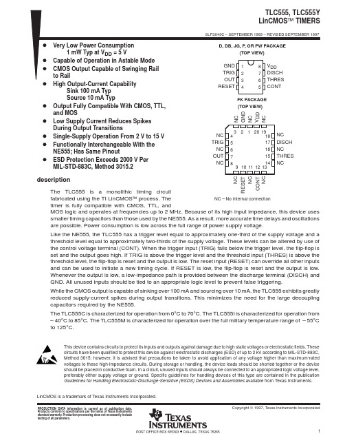
TLC555CDR;TLC555CPSR;TLC555IDR;TLC555QDR;TLC555CP;中文规格书,Datasheet资料
TRIG
2 R 7 1 GND DISCH
Pin numbers are for all packages except the FK package. RESET can override TRIG, which can override THRES.
POST OFFICE BOX 655303
• DALLAS, TEXAS 75265
1
/
TLC555 LinCMOS TIMER
SLFS043F − SEPTEMBER 1983 − REVISED FEBRUARY 2005
description (continued)
AVAILABLE OPTIONS† PACKAGED DEVICES TA 0°C to 70°C −40°C to 85°C −40°C to 125°C VDD RANGE 2 V to 15 V 3 V to 15 V 5 V to 15 V SMALL OUTLINE (D)‡ TLC555CD TLC555ID TLC555QD SSOP (DB)‡ TLC555CDB — — CHIP CARRIER (FK) — — — CERAMIC DIP (JG) — — — PLASTIC DIP (P) TLC555CP TLC555IP — TSSOP (PW)‡ TLC555CPW — —
−55°C to 125°C 5 V to 15 V TLC555MD — TLC555MFK TLC555MJG TLC555MP — † For the most current package and ordering information, see the Package Option Addendum at the end of this document, or see the TI web savailable taped and reeled. Add the R suffix to device type (e.g., TLC555CDR). FUNCTION TABLE RESET VOLTAGE‡ <MIN >MAX >MAX TRIGGER VOLTAGE‡ Irrelevant <MIN >MAX THRESHOLD VOLTAGE‡ Irrelevant Irrelevant >MAX OUTPUT L H L DISCHARGE SWITCH On Off On
[VIP专享]555定时器内部框图及电路工作原理
![[VIP专享]555定时器内部框图及电路工作原理](https://img.taocdn.com/s3/m/908d3aba192e45361166f546.png)
555定时器内部框图及电路工作原理本文介绍555定时器内部框图及电路工作原理:555定时器内部框图555集成时基电路称为集成定时器,是一种数字、模拟混合型的中规模集成电路,其应用十分广泛。
该电路使用灵活、方便,只需外接少量的阻容元件就可以构成单稳、多谐和施密特触发器,因而广泛用于信号的产生、变换、控制与检测。
它的内部电压标准使用了三个5K的电阻,故取名555电路。
其电路类型有双极型和CMOS型两大类,两者的工作原理和结构相似。
几乎所有的双极型产品型号最后的三位数码都是555或556;所有的CMOS产品型号最后四位数码都是7555或7556,两者的逻辑功能和引脚排列完全相同,易于互换。
555和7555是单定时器,556和7556是双定时器。
双极型的电压是+5V~+15V,输出的最大电流可达200mA,CMOS型的电源电压是+3V~+18V。
图8-1 555定时器内部框图555电路的工作原理555电路的内部电路方框图如图8-1所示。
它含有两个电压比较器,一个基本RS触发器,一个放电开关T,比较器的参考电压由三只5KΩ的电阻器构成分压,它们分别使高电平比较器A1同相比较端和低电平比较器A2的反相输入端的参考电平为和。
A1和A2的输出端控制RS触发器状态和放电管开关状态。
当输入信号输入并超过时,触发器复位,555的输出端3脚输出低电平,同时放电,开关管导通;当输入信号自2脚输入并低于时,触发器置位,555的3脚输出高电平,同时放电,开关管截止。
是复位端,当其为0时,555输出低电平。
平时该端开路或接VCC。
Vc是控制电压端(5脚),平时输出作为比较器A1的参考电平,当5脚外接一个输入电压,即改变了比较器的参考电平,从而实现对输出的另一种控制,在不接外加电压时,通常接一个0.01uf的电容器到地,起滤波作用,以消除外来的干扰,以确保参考电平的稳定。
T为放电管,当T导通时,将给接于脚7的电容器提供低阻放电电路。
LED驱动器中555定时器的应用

LED驱动器中555定时器的应用本文详细介绍如何使用便宜的555 定时器,在一些不需要LED 驱动器全部功能的应用中,代替微处理器对专用LED 驱动器实施控制。
这样做可让用户在降低总系统成本的同时,维持LED 驱动器的恒定电流。
专用LED 驱动器常常被设计为微处理器控制型,旨在实现诸如模拟或脉宽调制(PWM) LED 电流控制、每个LED 的独立控制、LED 状态和故障信息读取等特性。
对于一些仅要求恒定LED 电流的应用(例如:LED 照明或者发光)来说,可能不需要这些高级特性。
在这些应用中,诸如TLC555 的555 定时器可以代替微处理器,从而在实现LED 电流精确控制的同时降低系统成本,其与输入电压、温度和LED 正向压降无关。
例如,TLC5917 是一款专用LED 驱动器,其控制八个独立的恒流电流阱。
正常情况下,它要求一颗微处理器,以驱动四个数字输入信号。
指令/OE(允许输出)激活和关闭IC。
串行数据输入(SDI) 数据在时钟(CLK) 上升沿被时钟输入至IC 的输入移位寄存器。
移位寄存器中的数据在LE 下降沿(锁闭)转入内部开/关锁存器中。
当需要LED 电流的简单LED 开/关控制时,下列电路使用随处可见的555 定时器,来代替微处理器控制。
TLC5917 输出可以驱动八个独立LED,或者也可以并联其输出以提高电流能力来驱动单个更高功率的LED。
其内部电流设置寄存器具有默认启动值。
这些值与Rext 共同设置LED 电流。
在这种应用中,Rext 将每个输出的电流设置为IOUT = 18.75A / Rext = 18.75A / 178 ohm=0.105A。
将所有输出并联连接,得到0.842A 的LED 电流。
上电时,内部开/关锁存器默认将所有输出开或者关至0,因此在输出开。
555振荡电路芯片

555振荡电路芯片555振荡电路芯片是一种常见且广泛应用的集成电路芯片,通常用于产生稳定的方波信号或脉冲信号。
它是由美国电子工程师汉肯(Hans R. Camenzind)于1971年设计并推出的,由于其工作稳定性和多种应用场景,成为了电子工程师们常用的一种集成电路。
555振荡电路芯片内部结构简单,主要由比较器、RS触发器、放大器和电压稳定器组成。
它的输入引脚包括正常工作电压引脚Vcc和地引脚GND,以及外部引脚TRIGGER、THRESHOLD、RESET、OUT和DISCHARGE。
这些引脚通过外部元件的连接,可以实现不同类型的振荡和脉冲信号输出。
555振荡电路芯片常见的应用有以下几种:1.方波发生器:利用555振荡电路芯片的特性,可以很方便地实现稳定的方波信号输出。
通过调节电阻和电容的数值,可以控制方波的频率和占空比。
2.时钟电路:555振荡电路芯片可以产生稳定的脉冲信号,常用于数字系统的时钟电路。
通过调节电阻和电容的数值,可以控制脉冲信号的频率。
3.脉冲宽度调制(PWM):PWM是一种常见的调制技术,在电机控制、LED亮度调节等领域广泛应用。
通过调节电阻和电容的数值,可以控制PWM信号的频率和占空比,进而实现对输出信号的精确控制。
4.延时器:在某些场合,需要实现一定时间的延时操作。
555振荡电路芯片可以非常方便地实现延时功能,通过调节电阻和电容的数值,可以实现不同的延时时间。
5.触发器:通过改变输入引脚的电平状态,可以触发555振荡电路芯片的输出状态。
这种触发器在数字逻辑电路、传感器触发等应用中经常使用。
总的来说,555振荡电路芯片具有结构简单、使用方便、稳定性好的特点,被广泛应用于电子系统中。
无论是在实验室中的电子电路设计,还是在工业控制、通信设备、自动化系统等领域,都可以看到它的身影。
它不仅是电子工程师们的得力助手,也推动了电子技术的发展和应用的普及。
TLC555C芯片
LinCMOS is a trademark of Texas Instruments Incorporated.PRODUCTION DATA information is current as of publication date.Products conform to specifications per the terms of Texas Instrumentsstandard warranty. Production processing does not necessarily includetesting of all parameters.64POST OFFICE BOX 655303IMPORTANT NOTICETexas Instruments and its subsidiaries (TI) reserve the right to make changes to their products or to discontinue any product or service without notice, and advise customers to obtain the latest version of relevant information to verify, before placing orders, that information being relied on is current and complete. All products are sold subject to the terms and conditions of sale supplied at the time of order acknowledgement, including those pertaining to warranty, patent infringement, and limitation of liability.TI warrants performance of its semiconductor products to the specifications applicable at the time of sale in accordance with TI’s standard warranty. Testing and other quality control techniques are utilized to the extent TI deems necessary to support this warranty. Specific testing of all parameters of each device is not necessarily performed, except those mandated by government requirements.CERTAIN APPLICATIONS USING SEMICONDUCTOR PRODUCTS MAY INVOLVE POTENTIAL RISKS OF DEATH, PERSONAL INJURY, OR SEVERE PROPERTY OR ENVIRONMENTAL DAMAGE (“CRITICAL APPLICATIONS”). TI SEMICONDUCTOR PRODUCTS ARE NOT DESIGNED, AUTHORIZED, OR WARRANTED TO BE SUITABLE FOR USE IN LIFE-SUPPORT DEVICES OR SYSTEMS OR OTHER CRITICAL APPLICATIONS. INCLUSION OF TI PRODUCTS IN SUCH APPLICATIONS IS UNDERSTOOD TO BE FULLY AT THE CUSTOMER’S RISK.In order to minimize risks associated with the customer’s applications, adequate design and operating safeguards must be provided by the customer to minimize inherent or procedural hazards.TI assumes no liability for applications assistance or customer product design. TI does not warrant or represent that any license, either express or implied, is granted under any patent right, copyright, mask work right, or other intellectual property right of TI covering or relating to any combination, machine, or process in which such semiconductor products or services might be or are used. TI’s publication of information regarding any third party’s products or services does not constitute TI’s approval, warranty or endorsement thereof.Copyright © 1998, Texas Instruments Incorporated。
四线定时器工作原理
四线定时器工作原理
四线定时器(555)是一种常用的集成电路,它是由美国昇陽半導體公司(Signetics Corporation,现在的Philips半导体公司)于1972年开发的。
由于其稳定性好、工作可靠、应用广泛,被誉为集成电路中的“百搭王”。
四线定时器主要由电压比较器、RS触发器、输出级组成。
它的脚位分为8个引脚,其中2、6脚分别连接外部的电容、电阻,从而构成了一个RC震荡电路。
具体来说,当电容器充电至2/3VCC(正电源电压)时,输出为低电平;当电容器放电至1/3VCC时,输出为高电平。
也就是说,通过改变电容和电阻的值,就可以调节555芯片的输出频率和工作模式。
四线定时器可以设置单稳态和多稳态两种工作方式。
单稳态工作模式下,只产生一次输出脉冲,输出时间的长短由电容和电阻决定;多稳态工作模式下,则可以产生连续不断的输出波形,输出频率的大小也由电容和电阻决定。
除了以上两种基本的工作模式外,四线定时器还有一种脉冲宽度调制(PWM)的工作模式。
脉冲宽度调制就是根据输入信号的幅度和频率来改变输出脉冲的占空比。
在这种工作模式下,555输出脉冲的占空比与输入信号的频率成反比,与输入信号的幅度成正比。
总之,四线定时器的工作原理是通过外部导入的电容和电阻来调节内部的RC震荡电路,从而产生不同频率、不同角度和不同幅度的输出信号。
在电子电路设计中,四线定时器是一种非常实用的IC,广泛应用于计时、脉冲发生、频率测量等方面。
双555构成救护车的过程

双555构成救护车的过程
双555是指两个555计时器芯片。
这两个芯片可以通过连接它们的引脚和使用适当的电路来构成一个救护车的过程。
下面将详细介绍这个过程:
首先,需要将两个555芯片连接在一起。
其中一个芯片将被用作主控制器,它将控制救护车的各种功能。
另一个芯片将用作辅助控制器,它将用于产生声音和闪光灯效果。
主控制器的引脚2和6将被连接在一起,并连接到一个电容和一个可变电阻上。
这些元件的作用是控制主控制器的频率。
引脚3将被连接到一个电位器上,用于控制主控制器的占空比。
辅助控制器的引脚2和6也将被连接在一起,并连接到一个电容和一个可变电阻上,以控制它的频率。
引脚3将被连接到一个电位器上,控制其占空比。
引脚4和8将被连接到一个LED和一个电阻上,以产生闪光灯效果。
在正常运行时,主控制器将连接到一个蜂鸣器和一个电阻上,以产生声音效果。
同时,它将通过一个晶体管控制辅助控制器的闪光灯效果。
当需要救护车停止时,主控制器的输出将被连接到一个开关上,使其关闭。
总的来说,这个过程涉及到多个元件和电路的协调工作,以实现救护车的各种功
能。
双555芯片的优秀性能和易于控制的特点使得它们成为实现此类复杂控制过程的理想选择。
555定时器芯片工作原理

555定时器芯片工作原理555定时器芯片是一种非常常见的集成电路元件,广泛应用于电子电路中的计时、延时、脉冲调制、频率分割和脉冲发生等方面。
它由美国电子工程师汉克·贝克(Hans R. Camenzind)在1971年设计制造,并由Signetics 公司推出,后来被多家公司生产并改进。
本文将详细介绍555定时器芯片的工作原理。
555定时器芯片是一种运算放大器作为比较器工作的多种应用集成电路。
它的工作原理基于RC集成电路和开关原理。
内部主要包含一个SR触发器、两个比较器、RS触发器、电流源、电压分压网络、电压跟随器和输出缓冲器等核心组成部分。
555定时器芯片一共有8个引脚,分别是GND(地)、TRIG(触发)、THR(阈值)、RST(复位)、OUT(输出)、DIS(禁用)、VCC(正电源)和CTRL(控制电压)。
其中GND和VCC分别连接电路的地和正电源。
TRIG、THR、RST和CTRL引脚是外部控制引脚,用来控制定时器的计时、延时和触发等相关功能。
DIS引脚是使能引脚,用来开关定时器的运行。
OUT引脚是输出端,用来输出定时器的计时脉冲信号。
单稳态模式下,引脚TRIG和RST分别承担输入触发和复位功能。
当TRIG脚低电平上升至高电平时,输出OUT会从低电平上升至高电平,经过一个设定的时间后再自动恢复低电平。
这个时间间隔由外部连接的电阻和电容决定。
具体的工作原理如下:1.当TRIG脚从高电平变为低电平时,555芯片内部的比较器的输出会瞬间从低电平变为高电平。
2.RST脚是一个复位输入脚,连接电源正端的时候,外部电路通常会将该引脚与VCC相连,保持恒定的高电平传递给该引脚。
当TRIG脚由高电平变为低电平时,RST引脚会被拉低至一个低电平。
3.当TRIG脚由低电平变为高电平时,此时RST脚是一个低电平,即表示单稳态模式开始。
4.555芯片的连续可控电荷和电放电功能将起作用,电容开始充放电,计时。
一个完整555定时器基本指南

一个完整555 定时器基本指南一个完整555 定时器基本指南发布: | 作者:——| 来源: 华强| 查看:11648 次| 用户关注:本IC 是一个单片定时电路,可以产生精确和高度稳定的时间延误或振荡。
像其他常用的运算放大器,该IC 还非常可靠,易于使用,成本便宜。
它有一个应用,包括各种单稳态和非稳态多谐振荡器,DC - DC 转换器,数字逻辑探针,波形发生器,模拟频率计和转速表,温度测量和控制设备,稳压器等。
本文涵盖了所有的555 定时器IC 的基本方面。
您可能已经知道,SE / 东北555 Signetics 公司公司介绍了1970 年的一个定时器IC 。
在这篇文章中,我们涵盖约555 定时器IC 的以下信息。
1 。
介绍555 定时器IC(2)555 定时器IC 引脚配置(3)555 定时器的基础4。
框图5 ,工作原理6,下载数据手册1。
555 定时器IC 其中最通用的线性IC ,这是第一次在1970 年年初推出Signetic 给公司作为名义东南/东北555 定时器555 定时器。
本IC 是一个单片定时电路,可以产生精确和高度稳定的时间延误或振荡。
像其他常用的运算放大器,该IC 还非常可靠,易于使用,成本便宜。
它有一个应用,包括各种单稳态和非稳态多谐振荡器,DC - DC 转换器,数字逻辑探针,波形发生器,模拟频率计和转速表,温度测量和控制设备,稳压器等。
计时器基本上工作在两种模式之一,无论是作为一个单稳态多谐振荡器(一次性),或作为一个非稳态(自由运行)multivibrator.The SE 555 设计的工作温度范围从-55 ° C 125 °而东北555的工作温度范围0 °170 ' C555 定时器的重要特点是:从广泛到18 伏的电源电压范围从+ 5 伏特的电源。
下沉或采购200 毫安的负载电流。
所以只有很少的外部元件的正确选择允许超过几百公斤赫兹的频率几分钟的时间间隔,几分钟的时间间隔可分为,应正确选择外部元件。
555定时器的电路结构和管脚排列
555定时器是一种集成电路,广泛应用于各种定时和脉冲调制电路中。
本文将从电路结构和管脚排列两方面介绍555定时器的相关知识。
一、电路结构555定时器由比较器、触发器和输出驱动器组成,可以根据外部元件的连接方式实现不同的功能。
其内部电路主要包括电压分压器、比较器、RS触发器、输出级和电源级等组成。
1. 电压分压器:电压分压器由三分之二电阻器和一分之二电阻器组成,用于将电源电压分成三等分,分别为1/3 Vcc、2/3 Vcc和Vcc。
2. 比较器:555定时器内部包含两个比较器,它们分别连接在1/3Vcc和2/3 Vcc处。
当触发器的输入电压大于2/3 Vcc时,Q输出高电平;当触发器的输入电压小于1/3 Vcc时,Q输出低电平。
3. RS触发器:555定时器内部包含一个RS触发器,用于产生输出脉冲。
当触发器的S端输入高电平,R端输入低电平时,Q输出高电平;当S端输入低电平,R端输入高电平时,Q输出低电平。
4. 输出级和电源级:输出级包括电流比较器和输出级驱动电路,用于产生输出脉冲;电源级用于提供工作电源和稳定电压。
二、管脚排列555定时器一般有8个管脚,它们分别是Vcc、GND、TRIG、OUT、RESET、CTRL、DISCH和THR。
1. Vcc:Vcc是555定时器的电源正极接口,一般连接至正电源。
2. GND:GND是555定时器的电源负极接口,一般连接至负电源。
3. TRIG:TRIG是555定时器的触发输入管脚,用于接收外部触发脉冲信号。
4. OUT:OUT是555定时器的输出管脚,用于输出定时和脉冲信号。
5. RESET:RESET是555定时器的复位输入管脚,当该管脚输入低电平时,将清除输出并立即关闭。
6. CTRL:CTRL是控制电压输入管脚,用于调节电压水平以改变555定时器的参数。
7. DISCH:DISCH是放电管脚,用于外接放电二极管。
8. THR:THR是阈值输入管脚,用于设定阈值电平。
硅芯片拆解:早期 555 定时器芯片内部一览
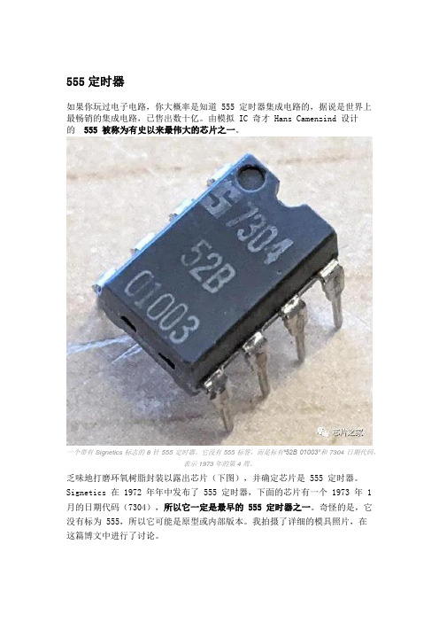
555定时器如果你玩过电子电路,你大概率是知道 555 定时器集成电路的,据说是世界上最畅销的集成电路,已售出数十亿。
由模拟 IC 奇才 Hans Camenzind 设计的555 被称为有史以来最伟大的芯片之一。
一个带有 Signetics 标志的 8 针 555 定时器。
它没有 555 标签,而是标有“52B 01003”和 7304 日期代码,表示 1973 年的第 4 周。
乏味地打磨环氧树脂封装以露出芯片(下图),并确定芯片是 555 定时器。
Signetics 在 1972 年年中发布了 555 定时器,下面的芯片有一个 1973 年 1 月的日期代码(7304),所以它一定是最早的 555 定时器之一。
奇怪的是,它没有标为 555,所以它可能是原型或内部版本。
我拍摄了详细的模具照片,在这篇博文中进行了讨论。
555 定时器的封装被打磨,露出硅芯片,中间的小方块。
简要说明555 定时器有数百种应用,从定时器或锁存器到压控振荡器或调制器的任何操作。
下图说明了 555 定时器如何作为一个简单的振荡器工作。
在 555 芯片内部,三个电阻形成一个分压器,产生 1/3 和 2/3 的电源电压的参考电压。
外部电容器将在这些限制之间充电和放电,从而产生振荡。
更详细地说,电容器将通过外部电阻器缓慢充电 (A),直到其电压达到 2/3 参考电压。
在该点 (B),上(阈值)比较器关闭触发器并关闭输出。
这会打开放电晶体管,使电容器 (C) 缓慢放电。
当电容器上的电压达到 1/3 参考电压 (D) 时,较低(触发)比较器打开,设置触发器和输出,循环重复。
电阻器和电容器的值控制时间,从微秒到几小时。
显示 555 定时器如何作为振荡器工作的图表。
在 555 定时器的控制下,外部电容器通过外部电阻器进行充电和放电。
总而言之,555 定时器的关键组件是检测电压上限和下限的比较器、设置这些限制的三电阻分压器以及跟踪电路是充电还是放电的触发器。
TLC555Q中文资料

FEATURESD PACKAGE(TOP VIEW)12348765GNDTRIGOUTRESETV DDDISCHTHRESCONT DESCRIPTION/ORDERING INFORMATIONLinCMOS™TIMERSLFS078–OCTOBER2006•Qualified for Automotive Applications•Low Supply Current Reduces Spikes DuringOutput Transitions•Very Low Power Consumption•Single-Supply Operation From2V to15V –1mW Typ at VDD=5V•Functionally Interchangeable With the NE555;•Capable of Operation in Astable ModeHas Same Pinout•CMOS Output Capable of Swinging Rail toRail•High Output-Current Capability–Sink100mA Typ–Source10mA Typ•Output Fully Compatible With CMOS,TTL,and MOSThe TLC555is a monolithic timing circuit fabricated using the TI LinCMOS™process.The timer is fully compatible with CMOS,TTL,and MOS logic and operates at frequencies up to2MHz.Because of its high input impedance,this device uses smaller timing capacitors than those used by the NE555.As a result,more accurate time delays and oscillations are possible.Power consumption is low across the full range of power supply voltage.Like the NE555,the TLC555has a trigger level equal to approximately one-third of the supply voltage and a threshold level equal to approximately two-thirds of the supply voltage.These levels can be altered by use of the control voltage terminal(CONT).When the trigger input(TRIG)falls below the trigger level,the flip-flop is set and the output goes high.If TRIG is above the trigger level and the threshold input(THRES)is above the threshold level,the flip-flop is reset and the output is low.The reset input(RESET)can override all other inputs and can be used to initiate a new timing cycle.If RESET is low,the flip-flop is reset and the output is low. Whenever the output is low,a low-impedance path is provided between the discharge terminal(DISCH)and GND.All unused inputs should be tied to an appropriate logic level to prevent false triggering.While the CMOS output is capable of sinking over100mA and sourcing over10mA,the TLC555exhibits greatly reduced supply-current spikes during output transitions.This minimizes the need for the large decoupling capacitors required by the NE555.The TLC555is characterized for operation over the full automotive temperature range of–40°C to125°C.ORDERING INFORMATION(1)T A V DD PACKAGE(2)ORDERABLE PART NUMBER TOP-SIDE MARKING –40°C to125°C5V to15V SOIC–D Reel of2500TLC555QDRQ1TLC555Q(1)For the most current package and ordering information,see the Package Option Addendum at the end of this document,or see the TIweb site at .(2)Package drawings,standard packing quantities,thermal data,symbolization,and PCB design guidelines are available at/sc/package.Please be aware that an important notice concerning availability,standard warranty,and use in critical applications of TexasInstruments semiconductor products and disclaimers thereto appears at the end of this data sheet.LinCMOS is a trademark of Texas Instruments.PRODUCTION DATA information is current as of publication date.Copyright©2006,Texas Instruments Incorporated Products conform to specifications per the terms of the TexasInstruments standard warranty.Production processing does notnecessarily include testing of all parameters.GNDCONTTHRESTRIGDISCHOUTLinCMOS™TIMERSLFS078–OCTOBER 2006FUNCTION TABLETHRESHOLD RESET VOLTAGE (1)TRIGGER VOLTAGE (1)OUTPUTDISCHARGE SWITCHVOLTAGE (1)<MIN Irrelevant Irrelevant L On >MAX <MIN Irrelevant H Off >MAX >MAX >MAX LOn>MAX>MAX<MINAs previously established(1)For conditions shown as MIN or MAX,use the appropriate value specified under electrical characteristics.FUNCTIONAL BLOCK DIAGRAMA.RESET can override TRIG,which can override THRES.2Submit Documentation FeedbackLinCMOS™TIMERSLFS078–OCTOBER 2006EQUIVALENT SCHEMATIC3Submit Documentation FeedbackAbsolute Maximum Ratings (1)Dissipation RatingsRecommended Operating ConditionsLinCMOS™TIMERSLFS078–OCTOBER 2006over operating free-air temperature range (unless otherwise noted)MINMAX UNIT V DD Supply voltage (2)18V V I Input voltage rangeAny input–0.3V DD V Sink current,discharge or output 150mA I OSource current,output15mASee Dissipation Continuous total power dissipationRating Table T A Operating free-air temperature range –40125°C T stgStorage temperature range –65150°C Lead temperature1,6mm (1/16ch)from case for 10s 260°C HBM (Human Body Model)ESD1000V (1)Stresses beyond those listed under "absolute maximum ratings"may cause permanent damage to the device.These are stress ratings only and functional operation of the device at these or any other conditions beyond those indicated under "recommended operating conditions"is not implied.Exposure to absolute-maximum-rated conditions for extended periods may affect device reliability.(2)All voltage values are with respect to network GND.T A ≤25°C DERATING FACTOR T A =125°C PACKAGEPOWER RATINGABOVE T A =25°CPOWER RATINGD725mW5.8mW/°C145mWMINMAX UNIT V DD Supply voltage215V T AOperating free-air temperature–40125°C4Submit Documentation FeedbackElectrical Characteristics LinCMOS™TIMER SLFS078–OCTOBER2006VDD=5V,at specified free-air temperature(unless otherwise noted)TESTPARAMETER T A(1)MIN TYP MAX UNITCONDITIONS25°C 2.8 3.3 3.8V IT Threshold voltage VFull range 2.7 3.925°C10I IT Threshold current pAMAX500025°C 1.36 1.66 1.96V I(TRIG)Trigger voltage VFull range 1.26 2.0625°C10I I(TRIG)Trigger current pAMAX500025°C0.4 1.1 1.5V I(RESET)Reset voltage VFull range0.3 1.825°C10I I(RESET)Reset current pAMAX5000Control voltage(open circuit)as a percentage ofMAX66.7% supply voltage25°C0.140.5 Discharge switch on-state voltage I OL=10mA VFull range0.625°C0.1 Discharge switch off-state current nAMAX12025°C 4.1 4.8V OH High-level output voltage I OH=–1mA VFull range 4.125°C0.210.4I OL=8mAFull range0.625°C0.130.3V OL Low-level output voltage I OL=5mA VFull range0.4525°C0.080.3I OL=3.2mAFull range0.425°C170350I DD Supply current(2)µAFull range700(1)Full range T A is–40°C to125°C.(2)These values apply for the expected operating configurations in which THRES is connected directly to DISCH or TRIG.5Submit Documentation FeedbackElectrical CharacteristicsLinCMOS™TIMERSLFS078–OCTOBER 2006V DD =15V,at specified free-air temperature (unless otherwise noted)TEST PARAMETERT A (1)MIN TYP MAX UNIT CONDITIONS25°C 9.451010.55V IT Threshold voltage V Full range 9.3510.6525°C 10I IT Threshold current pA MAX 500025°C 4.6555.35V I(TRIG)Trigger voltage V Full range 4.555.4525°C 10I I(TRIG)Trigger currentpA MAX 500025°C 0.4 1.11.5V I(RESET)Reset voltage V Full range 0.31.825°C 10I I(RESET)Reset currentpA MAX 5000Control voltage (open circuit)as a percentage of MAX66.7%supply voltage25°C 0.771.7Discharge switch on-state voltage I OL =100mAV Full range 1.825°C 0.1Discharge switch off-state currentnAMAX12025°C 12.514.2I OH =–10mAFull range 12.525°C 13.514.6V OHHigh-level output voltageI OH =–5mA VFull range 13.525°C 14.214.9I OH =–1mA Full range 14.225°C 1.283.2I OL =100mAFull range 3.825°C 0.631V OLLow-level output voltageI OL =50mA VFull range 1.525°C 0.120.3I OL =10mAFull range 0.4525°C 360600I DD Supply current (2)µA Full range1000(1)Full range T A is –40°C to 125°C.(2)These values apply for the expected operating configurations in which THRES is connected directly to DISCH or TRIG.6Submit Documentation FeedbackOperating Characteristics Electrical Characteristics LinCMOS™TIMER SLFS078–OCTOBER2006V DD =5V,TA=25°C(unless otherwise noted)PARAMETER TEST CONDITIONS MIN TYP MAX UNITV DD=5V to15V,C T=0.1µF,Initial error of timing interval(1)13%R A=R B=1kΩto100kΩ(2)V DD=5V to15V,C T=0.1µF,Supply voltage sensitivity of timing interval0.10.5%/VR A=R B=1kΩto100kΩ(2)t r Output pulse rise time R L=10MΩ,C L=10pF2075ns t f Output pulse fall time R L=10MΩ,C L=10pF1560nsR A=470Ω,C T=200pF,f max Maximum frequency in astable mode 1.2 2.1MHzR B=200Ω(2)(1)Timing interval error is defined as the difference between the measured value and the average value of a random sample from eachprocess run.(2)R A,R B,and C T are as defined in Figure1.V DD =5V,TA=25°C(unless otherwise noted)TESTPARAMETER MIN TYP MAX UNITCONDITIONSV IT Threshold voltage 2.8 3.3 3.8VI IT Threshold current10pAV I(TRIG)Trigger voltage 1.36 1.66 1.96VI I(TRIG)Trigger current10pAV I(RESET)Reset voltage0.4 1.1 1.5VI I(RESET)Reset current10pAControl voltage(open circuit)as a percentage of supply voltage66.7%Discharge switch on-state voltage I OL=10mA0.140.5VDischarge switch off-state current0.1nAV OH High-level output voltage I OH=–1mA 4.1 4.8VI OL=8mA0.210.4V OL Low-level output voltage I OL=5mA0.130.3VI OL=3.2mA0.080.3I DD Supply current(1)170350µA(1)These values apply for the expected operating configurations in which THRES is connected directly to DISCH or TRIG.7Submit Documentation FeedbackTYPICAL CHARACTERISTICSD i s c h a r g e S w i t c h O n -S t a t e R e s i s t a n c e −DISCHARGE SWITCH ON-STATE RESISTANCEvsFREE-AIR TEMPERATUREΩT A − Free-Air Temperature − °C24681216PROPAGATION DELAY TIMES TO DISCHARGE OUTPUT FROM TRIGGER AND THRESHOLDSHORTED TOGETHERvsSUPPLY VOLTAGE1014V DD − Supply Voltage − V2018P H L t ,P L H t − P r o p a g a t i o n D e l a y T i m e s − n sLinCMOS™TIMERSLFS078–OCTOBER 2006Figure 1.A.The effects of the load resistance on these values must be taken into account separately.Figure 2.8Submit Documentation FeedbackAPPLICATION INFORMATIONLR R V DD2/3 V DD1/3 V DDGNDCIRCUITTRIGGER AND THRESHOLD VOLTAGE WAVEFORMt c(H)[C T (R A )R B )In 2(In 2+0.693)t c(L)[C T R B In 2Period +t c(H))t c(L)[C T (R A )2R B)In 2Output driver duty cycle +t c(L)t c(H))t c(L)[1–R B R A )2R BOutput waveform duty cycle +t c(H)t c(H))t c(L)[R B R A )2R B LinCMOS™TIMERSLFS078–OCTOBER 2006Figure 3.Astable OperationConnecting TRIG to THRES,as shown in Figure 3,causes the timer to run as a multivibrator.The capacitor C T charges through R A and R B to the threshold voltage level (approximately 0.67V DD )and then discharges through R B only to the value of the trigger voltage level (approximately 0.33V DD ).The output is high during the charging cycle (t c(H))and low during the discharge cycle (t c(L)).The duty cycle is controlled by the values of R A ,R B ,and C T as shown in the following equations.The 0.1-µF capacitor at CONT in Figure 3decreases the period by about 10%.The formulas shown above do not allow for any propagation delay times from the TRIG and THRES inputs toDISCH.These delay times add directly to the period and create differences between calculated and actual values that increase with frequency.In addition,the internal on-state resistance (r on )during discharge adds to R B to provide another source of timing error in the calculation when R B is very low or r on is very high.9Submit Documentation Feedback t c(H)+C T(R A)R B)Inƪ3–expǒ–t PLHC T(R B)r on)Ǔƫ)t PHLt c(L)+C T(R B)r on)Inƪ3–expǒ–t PHLC T(R A)R B)Ǔƫ)t PLHcan be substituted with good results.Duty cycles less than50%t c(H)t c(H))t c(L)require thatt c(H)t c(L)<1andLinCMOS™TIMERSLFS078–OCTOBER2006APPLICATION INFORMATION(continued)The following equations provide better agreement with measured values.These equations and those given previously are similar in that a time constant is multiplied by the logarithm of a number or function.The limit values of the logarithmic terms must be between In2at low frequencies and In3 at extremely high frequencies.For a duty cycle close to50%,an appropriate constant for the logarithmic termspossibly R A≤r on.These conditions can be difficult to obtain.In monostable applications,the trip point on TRIG can be set by a voltage applied to CONT.An input voltage between10%and80%of the supply voltage from a resistor divider with at least500-µA bias provides good results.10Submit Documentation FeedbackPACKAGING INFORMATION Orderable DeviceStatus (1)Package Type Package Drawing Pins Package Qty Eco Plan (2)Lead/Ball Finish MSL Peak Temp (3)TLC555QDRQ1ACTIVE SOIC D 82500Green (RoHS &no Sb/Br)CU NIPDAU Level-1-260C-UNLIM (1)The marketing status values are defined as follows:ACTIVE:Product device recommended for new designs.LIFEBUY:TI has announced that the device will be discontinued,and a lifetime-buy period is in effect.NRND:Not recommended for new designs.Device is in production to support existing customers,but TI does not recommend using this part in a new design.PREVIEW:Device has been announced but is not in production.Samples may or may not be available.OBSOLETE:TI has discontinued the production of the device.(2)Eco Plan -The planned eco-friendly classification:Pb-Free (RoHS),Pb-Free (RoHS Exempt),or Green (RoHS &no Sb/Br)-please check /productcontent for the latest availability information and additional product content details.TBD:The Pb-Free/Green conversion plan has not been defined.Pb-Free (RoHS):TI's terms "Lead-Free"or "Pb-Free"mean semiconductor products that are compatible with the current RoHS requirements for all 6substances,including the requirement that lead not exceed 0.1%by weight in homogeneous materials.Where designed to be soldered at high temperatures,TI Pb-Free products are suitable for use in specified lead-free processes.Pb-Free (RoHS Exempt):This component has a RoHS exemption for either 1)lead-based flip-chip solder bumps used between the die and package,or 2)lead-based die adhesive used between the die and leadframe.The component is otherwise considered Pb-Free (RoHS compatible)as defined above.Green (RoHS &no Sb/Br):TI defines "Green"to mean Pb-Free (RoHS compatible),and free of Bromine (Br)and Antimony (Sb)based flame retardants (Br or Sb do not exceed 0.1%by weight in homogeneous material)(3)MSL,Peak Temp.--The Moisture Sensitivity Level rating according to the JEDEC industry standard classifications,and peak solder temperature.Important Information and Disclaimer:The information provided on this page represents TI's knowledge and belief as of the date that it is provided.TI bases its knowledge and belief on information provided by third parties,and makes no representation or warranty as to the accuracy of such information.Efforts are underway to better integrate information from third parties.TI has taken and continues to take reasonable steps to provide representative and accurate information but may not have conducted destructive testing or chemical analysis on incoming materials and chemicals.TI and TI suppliers consider certain information tobe proprietary,and thus CAS numbers and other limited information may not be available for release.In no event shall TI's liability arising out of such information exceed the total purchase price of the TI part(s)at issue in this document sold by TI to Customer on an annual basis.PACKAGE OPTION ADDENDUM 16-May-2007Addendum-Page 1IMPORTANT NOTICETexas Instruments Incorporated and its subsidiaries(TI)reserve the right to make corrections,modifications,enhancements, improvements,and other changes to its products and services at any time and to discontinue any product or service without notice. Customers should obtain the latest relevant information before placing orders and should verify that such information is current and complete.All products are sold subject to TI’s terms and conditions of sale supplied at the time of order acknowledgment.TI warrants performance of its hardware products to the specifications applicable at the time of sale in accordance with TI’s standard warranty.Testing and other quality control techniques are used to the extent TI deems necessary to support this warranty.Except where mandated by government requirements,testing of all parameters of each product is not necessarily performed.TI assumes no liability for applications assistance or customer product design.Customers are responsible for their products and applications using TI components.To minimize the risks associated with customer products and applications,customers should provide adequate design and operating safeguards.TI does not warrant or represent that any license,either express or implied,is granted under any TI patent right,copyright,mask work right,or other TI intellectual property right relating to any combination,machine,or process in which TI products or services are rmation published by TI regarding third-party products or services does not constitute a license from TI to use such products or services or a warranty or endorsement e of such information may require a license from a third party under the patents or other intellectual property of the third party,or a license from TI under the patents or other intellectual property of TI. Reproduction of information in TI data books or data sheets is permissible only if reproduction is without alteration and is accompanied by all associated warranties,conditions,limitations,and notices.Reproduction of this information with alteration is an unfair and deceptive business practice.TI is not responsible or liable for such altered documentation.Resale of TI products or services with statements different from or beyond the parameters stated by TI for that product or service voids all express and any implied warranties for the associated TI product or service and is an unfair and deceptive business practice.TI is not responsible or liable for any such statements.TI products are not authorized for use in safety-critical applications(such as life support)where a failure of the TI product would reasonably be expected to cause severe personal injury or death,unless officers of the parties have executed an agreement specifically governing such use.Buyers represent that they have all necessary expertise in the safety and regulatory ramifications of their applications,and acknowledge and agree that they are solely responsible for all legal,regulatory and safety-related requirements concerning their products and any use of TI products in such safety-critical applications,notwithstanding any applications-related information or support that may be provided by TI.Further,Buyers must fully indemnify TI and its representatives against any damages arising out of the use of TI products in such safety-critical applications.TI products are neither designed nor intended for use in military/aerospace applications or environments unless the TI products are specifically designated by TI as military-grade or"enhanced plastic."Only products designated by TI as military-grade meet military specifications.Buyers acknowledge and agree that any such use of TI products which TI has not designated as military-grade is solely at the Buyer's risk,and that they are solely responsible for compliance with all legal and regulatory requirements in connection with such use.TI products are neither designed nor intended for use in automotive applications or environments unless the specific TI products are designated by TI as compliant with ISO/TS16949requirements.Buyers acknowledge and agree that,if they use anynon-designated products in automotive applications,TI will not be responsible for any failure to meet such requirements. Following are URLs where you can obtain information on other Texas Instruments products and application solutions:Products ApplicationsAmplifiers Audio /audioData Converters Automotive /automotiveDSP Broadband /broadbandInterface Digital Control /digitalcontrolLogic Military /militaryPower Mgmt Optical Networking /opticalnetworkMicrocontrollers Security /securityRFID Telephony /telephonyLow Power /lpw Video&Imaging /videoWirelessWireless /wirelessMailing Address:Texas Instruments,Post Office Box655303,Dallas,Texas75265Copyright©2007,Texas Instruments Incorporated。
555定时器芯片引脚参数及功能

555定时器芯片引脚参数及功能摘要:555定时器是一种集成电路芯片,常被用于定时器、脉冲产生器和振荡电路。
555可被作为电路中的延时器件、触发器或起振元件。
下面我们来看看555定时器引脚图和555芯片的引脚参数及功能。
555定时器是一种集成电路芯片,常被用于定时器、脉冲产生器和振荡电路。
555可被作为电路中的延时器件、触发器或起振元件。
下面我们来看看555定时器引脚图和555芯片的引脚参数及功能。
555引脚图一、555定时器引脚功能:引脚1:GND(地),功能:接地,作为低电平(0V)引脚2:TRIG(触发),功能:当此引脚电压降至1/3VCC(或由控制端决定的阈值电压)时输出端给出高电平。
引脚3:OUT(输出),功能:输出高电平(+VCC)或低电平。
引脚4:RST(复位),功能:当此引脚接高电平时定时器工作,当此引脚接地时芯片复位,输出低电平。
引脚5:ctrl(控制),功能:控制芯片的阈值电压。
(当此管脚接空时默认两阈值电压为1/3VCC与2/3VCC).引脚6:THR(阈值),功能:当此引脚电压升至2/3VCC(或由控制端决定的阈值电压)时输出端给出低电平。
引脚7:DIS(放电),功能:内接OC门,用于给电容放电。
引脚8:V+,VCC(供电),功能:提供高电平并给芯片供电。
二、555定时器参数(以ne555参数为主)供电电压(VCC):4.5-16V额定工作电流(VCC=+5V):3-6mA额定工作电流(VCC=+15V):10-15mA最大输出电流:200mA最大功耗:600mW最低工作功耗:30mW(5V),225mW(15V)温度范围:0-70°C以上便是555引脚图以及555芯片引脚功能,以及555定时器的参数相关信息,希望对大家有所帮助。
tlc555dr
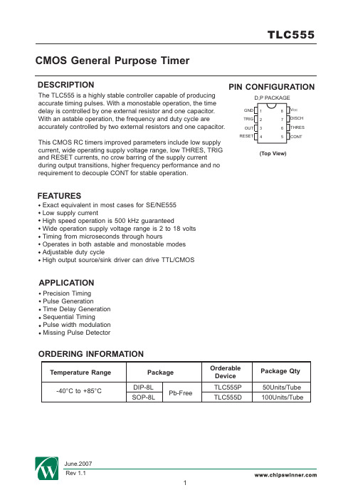
DESCRIPTIONFEATURESAPPLICATIONORDERING INFORMATIONTemperature Range Package Orderable Device Package Qty SOP-8LPb-FreeTLC555P TLC555D50Units/Tube 100Units/TubeDIP-8L CMOS General Purpose TimerPIN CONFIGURATION(Top View)Exact equivalent in most cases for SE/NE555Low supply currentHigh speed operation is 500 kHz guaranteedWide operation supply voltage range is 2 to 18 volts Timing from microseconds through hoursOperates in both astable and monostable modes Adjustable duty cycleHigh output source/sink driver can drive TTL/CMOSPrecision Timing Pulse GenerationTime Delay Generation Sequential TimingPulse width modulation Missing Pulse Detector12348765The TLC555 is a highly stable controller capable of producing accurate timing pulses. With a monostable operation, the time delay is controlled by one external resistor and one capacitor. With an astable operation, the frequency and duty cycle areaccurately controlled by two external resistors and one capacitor.This CMOS RC timers improved parameters include low supply current, wide operating supply voltage range, low THRES, TRIG and RESET currents, no crow barring of the supply current during output transitions, higher frequency performance and no requirement to decouple CONT for stable operation.-40°C to +85°CD,P PACKAGEGND TRIG OUT RESETV CC DISCH THRES CONTSCHEMATIC DIAGRAMFigure 1. Block DiagramFigure 2. Cricuit SchematicTRUTH TABLETHRES TRIG RESET OUT DISCH X L HSTABLE> V CC *1/3ON L L H H HXX STABLE OFFON > V CC *2/3< V CC *2/3> V CC *1/3< V CC *1/3GNDRESET OUTPUT(OUT)ABSOLUTE MAXIMUM RATINGSParameterSymbol Value Unit Supply Voltage V V V I O 0 to 18mA 100-0.3 to V CC +0.3200TRIG Voltage V CC Output Current THRES Voltage V TH V TRIG RECOMMENDED OPERATING CONDITIONSMin Max Supply Voltage 18+85I O 220-40V CC Output Current Operating TemperatureT ARESET Voltage Power Dissipation Storage TemperatureLead Temperature, 1mm from Case for 10 SecondsV RST P D T STG T LV mW °C °C-65 to +150260-0.3 to V CC +0.3-0.3 to V CC +0.3ParameterSymbol Unit V mA °CDC ELECTRICAL CHARACTERISTICSMin Max Threshold Voltage 0.70 V CC Reset Voltage V RST V CC =5V Control Voltage LeadT A =-40to +85°CV TH Output Voltage Low Trigger Voltage V TRIG Parameter Symbol UnitV Typ0.65 V CC Test Conditions T A =25±10°C T A =-40 to +85°C 0.65 V CC 0.70 V CC V CC =5V T A =25±10°C T A =-40 to +85°C 0.31 V CC 0.28 V CC0.36 V CC 0.40 V CC V CC =2to 18VT A =25±10°C T A =-40 to +85°C0.4 V CC 0.2 V CC 1.0 V CC 1.5 V CC T A =25±10°CT A =-40 to +85°CV CV0.69 V CC 0.65 V CC0.60 V CC 0.80 V CC0.4V CC =5V, I OL =3.2mAOutput Voltage High T A =25±10°C 1.50.61.0V CC =15V,I OL =20mA V CC =5V, I OL =3.2mAV CC =15V,I OL =20mA V OLV OHI OH =-0.8mAV CC =5V, T A =25±10°C V CC =15V,T A =25±10°C4.014.33.514V CC =5V, T A =-40 to +85°C V CC =15V,T A =-40 to +85°CParameterSymbolUnitRise(Fall) Time of Output 0.06kHz 75ns 150355Drift with Supply Voltage t THL , t TLH R L =1 to 100kΩ, C L =0.1μF,Guaranteed Max Osc. Freq.R L =10MΩ, C L =10pF f MAX Initial Accuracy Drift with TemperatureAstable,V CC =2~18VACCUR αfΔf%%/°C %/V0.020.0370500DC ELECTRICAL CHARACTERISTICS(CONTINUED)MinMax Supply Current200V CC =2V I CCParameterSymbolUnitμA TypTest Conditions T A =25±10°CT A =-40 to +85°C300V CC =18V400600AC ELECTRICAL CHARACTERISTICSV CC =18V V CC =2V Test ConditionsMin Max Typ T A =25±10°CT A =-40 to +85°C T A =25±10°CT A =-40 to +85°C 200T A =0 to 70°CV CC =15VV CC =5V V CC =10V T A =25±10°C T A =-40 to +85°C R L =1 to 100kΩ, C L =0.1μF,V CC =5V 63Note 1: R L ,C L are defined in Figure 5.Figure 3. Swithcing WaveformsV CCPIN FUNCTION DESCRIPTION1GND DescriptionTRIG Circuit ground pin.OUTRESETCONT 2345678This trigger pin is the input to the comparator B and is used to set the latch, which in turn causes the output to go high. This is the beginning of the timingsequence in monostable operation. Triggering is accomplished by taking the pinfrom above to below a voltage level of 1/3 Vcc. The action of the TRIG pin is level-sensitive, allowing slow rate-of-change waveforms, as well as pulses, to be used as trigger sources.The state of the output pin will always reflect the inverse of the logic state of the latch. This relationship may be best explained in terms of latch-input trigger conditions. To trigger the output to a high condition, the TRIG pin is momen-tarily taken from a higher to a lower level. The output can be returned to a low state by causing the THRES pin to go from a lower to a higher level, which resets the latch. The output can also be made to go low by taking the RESET pin to a low state near ground.This reset pin is also used to reset the latch and return the output to a low state.This control voltage pin allows direct access to the 2/3 Vcc voltage-dividerpoint, the reference level for the comparator A. It also allows indirect access tothe comparator B, as there is a 2:1 divider from this point to the comparator Breference input. Use of this terminal is the option of the user, but it does allow extreme flexibility by permitting modification of the timing period, resetting of the comparator, etc.THRES This is one input to the comparator A and is used to reset the latch, whichcauses the OUT pin to go low. Resetting via this terminal is accomplished bytaking the terminal from below to above a voltage level of 2/3 Vcc. The action of the THRES pin is level sensitive, allowing slow rate-of-change waveforms.DISCH This pin is low resistance to ground when the OUT pin is low, and is highresistance to ground when the OUT pin is high. Usually the timing capacitor isconnected between DISCH pin and ground, and is discharged when it effec-tively shorted to ground.V CCPositive supply voltageMonostable operation is initiated when TRIG voltage falls below the trigger threshold. Once initiated, the sequence ends only if TRIG is high at the end of the timing interval. Because of the threshold level and saturation voltage of Q1, the output pulse duration is approximately t W = 1.1R A C. The threshold levels and charge rates both are directly proportional to the supply voltage, V CC . The timing interval is, therefore, independent of the supply voltage, so long as the supply voltage is constant during the time interval.Applying a negative-going trigger pulse simultaneously to RESET and TRIG during the timing interval discharges C and reinitiates the cycle, commencing on the positive edge of the reset pulse. The output is held low as long as the reset pulse is low. To prevent false triggering, when RESET is not used, it should be connected to V CC.Figure 4. Cricuit for Monostable OperationAs shown in Figure 5, adding a second resistor, R B , connecting the TRIG input to the THRES input causes the timer to self-trigger and run as a multi-vibrator. The capacitor C charges through R A and R B and then discharges through R B only. Therefore, the duty cycle is controlled by the values of R A and R B .This astable connection results in capacitor C charging and discharging between thethreshold-voltage level (≈0.67V CC ) and the trigger-voltage level (≈0.33V CC ). As in the monos-table circuit, charge and discharge times (and, therefore, the frequency and duty cycle) are independent of the supply voltage.InputAstable OperationAPPLICATION INFORMATION Monostable OperationFor monostable operation, any of these timers can be connected as shown in Figure 4. If the output is low, application of a negative-going pulse to the TRIG sets theflip-flop, drives the output high, and turns off Q1. Capacitor C then is charged through R A until the voltage across the capacitor reaches the threshold voltage of the THRES input. If TRIG has returned to a high level, the output of the threshold comparator resets the flip-flop, drives the output low, and discharges C through Q1.t H = 0.693(R A +R B )C t L = 0.693R B COther useful relationships are shown below.period = t H +t L = 0.693(R A +2R B )C frequency ≈Output driver duty cycle =Output waveform duty cycle = Low-to-high ratio =The output high-level duration t H and low-level duration t L can be calculated as follows:Missing-Pulse DetectorThe circuit shown in Figure 6 can be used to detect a missing pulse or abnormally long spacing between consecutive pulses in a train of pulses. The timing interval of the monos-table circuit is retriggered continuously by the input pulse train as long as the pulse spacing is less than the timing interval. A longer pulse spacing, missing pulse, or terminated pulse train permits the timing interval to be completed, thereby generating an output pulse.Figure 6. Cricuit for Missing-pulse Detector1.44 /((R A +2R B )C)t L /(t H +t L )R B /(R A +2R B )=t H /(t H +t L )R B /(R A +2R B )=1 -t L /t H R B /(R A +R B )=OutputFigure 5. Cricuit for Astable OperationOuputR RPulse-Position ModulationAs shown in Figure 8, any of these timers can be used as a pulse-position modulator. This application modulates the threshold voltage and, thereby, the time delay, of a free-running oscillator.Figure 8. Cricuit for Pulse-position ModulationFigure 7. Cricuit for Pulse-width ModulationInputOutputInputOutputClock InputPulse-Width ModulationThe operation of the timer can be modified by modulating the internal threshold and trigger voltages, which is accomplished by applying an external voltage (or current) to CONT. Figure 7 shows a circuit for pulse-width modulation. A continuous input pulse train triggers the monostable circuit, and a control signal modulates the threshold voltage.PHYSICAL DIMENSIONS SOP8LDIP8L。
555定时器及各脚功能
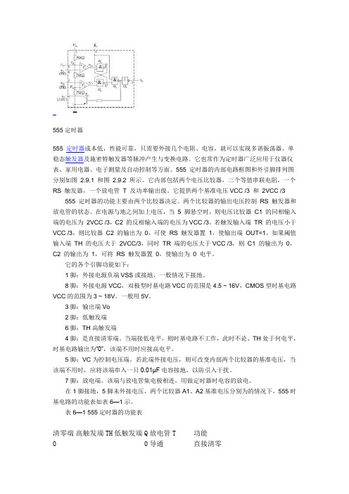
555定时器555 定时器成本低,性能可靠,只需要外接几个电阻、电容,就可以实现多谐振荡器、单稳态触发器及施密特触发器等脉冲产生与变换电路。
它也常作为定时器广泛应用于仪器仪表、家用电器、电子测量及自动控制等方面。
555 定时器的内部电路框图和外引脚排列图分别如图2.9.1 和图2.9.2 所示。
它内部包括两个电压比较器,三个等值串联电阻,一个RS 触发器,一个放电管T 及功率输出级。
它提供两个基准电压VCC /3 和2VCC /3 555 定时器的功能主要由两个比较器决定。
两个比较器的输出电压控制RS 触发器和放电管的状态。
在电源与地之间加上电压,当5 脚悬空时,则电压比较器C1 的同相输入端的电压为2VCC /3,C2 的反相输入端的电压为VCC /3。
若触发输入端TR 的电压小于VCC /3,则比较器C2 的输出为0,可使RS 触发器置1,使输出端OUT=1。
如果阈值输入端TH 的电压大于2VCC/3,同时TR 端的电压大于VCC /3,则C1 的输出为0,C2 的输出为1,可将RS 触发器置0,使输出为0 电平。
它的各个引脚功能如下:1脚:外接电源负端VSS或接地,一般情况下接地。
8脚:外接电源VCC,双极型时基电路VCC的范围是4.5 ~ 16V,CMOS型时基电路VCC的范围为3 ~ 18V。
一般用5V。
3脚:输出端Vo2脚:低触发端6脚:TH高触发端4脚:是直接清零端。
当端接低电平,则时基电路不工作,此时不论、TH处于何电平,时基电路输出为“0”,该端不用时应接高电平。
5脚:VC为控制电压端。
若此端外接电压,则可改变内部两个比较器的基准电压,当该端不用时,应将该端串入一只0.01μF电容接地,以防引入干扰。
7脚:放电端。
该端与放电管集电极相连,用做定时器时电容的放电。
在1脚接地,5脚未外接电压,两个比较器A1、A2基准电压分别为的情况下,555时基电路的功能表如表6—1示。
表6—1 555定时器的功能表清零端高触发端TH 低触发端Q 放电管T 功能0 0 导通直接清零××1 0 1 x 保持上一状态保持上一状态1 1 0 x 保持上一状态保持上一状态1 0111导通截止置1清零。
555定时器工作原理

5脚为电压控制端在此端可以加一电压,以改变 比较器的参考电压,不用时,经 0.01uF 的电容 接地以防止引入干扰 6脚为高电平触发端。当输入电压低于2/3Vcc时, C1 的输出为高电平,基本 RS 触发器保持不变; 当输入电压高于 2/3Vcc 时, C1 的输出为低电压, 使基本RS触发器置“0”。 7脚为放电端,当触发器Q端为“0”时,放电三 极管T导通,常用于给外接电容元件提供放电通 路。 8脚电源端,可在5-18V范围内使用。
555定时器各引脚的功能
1脚为接地端 2 脚为低电平触发器 。当 2 端的输入电压高于 1/3Vcc 时, C2 的输出为高电平,基本 RS 触发器 保持不变,当输入电压低于 1/3Vcc 时, C2 的输 出为低电平,使基本RS触发器置1 3 脚为输出端,输出电流可达 200mA ,因此可直 接驱动继电器,发光二极管,扬声器等,输出 高电平电压低于电源电压Vcc大约1-3V 4脚为基本RS触发器的复位端,在此输入负脉冲 (或使其低于0.7v)而使触发器复位
在接通电源后,Vcc通过R1、R2对电容C充电 , 在Uc未达到 1/3Vcc和 2/3Vcc之前, 6号、 2号引 脚状态为 0 、 0 和 0 、 1 ,输出 U0 为 1 ,放电管 T 截 止,当电容C被充电达到Uc>=2/3Vcc时,6号,2 号引脚状态为1,1,则输出U0翻转为0,放电管T 导通,此时电容C开始通过R2和T放电,使Uc按指 数曲线下降。当 Uc处于 2/3Vcc 和 1/3Vcc之间时, 6号、2号引脚状态为0,1,输出维持为0,电容C 继续放电,直到 Uc<=1/3Vcc,使 6 号, 2 号引脚 状态为0,0,输出U0又翻转为1态,放电管T截止, 电容C又开始充电,这样周而复始震荡下去,输 出U0位矩形波
555芯片接法
555芯片接法摘要:一、555 芯片简介1.555 芯片的基本功能2.广泛应用于各种电子设备二、555 芯片引脚接法1.引脚功能概述2.常见接法及应用场景a) 基本单稳态电路b) 施密特触发器c) 多谐振荡器d) 脉冲宽度调制器e) 充电/放电电路三、555 芯片接法注意事项1.电源电压范围2.电阻值的选取3.电容值的选取4.其他元件的连接四、实际应用案例1.制作简单的计时器2.制作闪光灯控制器3.制作音频发生器正文:555 芯片接法详解一、555 芯片简介555 芯片,全称为555 定时器,是一种常用的集成电路,具有固定的引脚功能。
它可以根据外部元件的连接方式来实现不同的功能,如计时、计数、脉冲生成等。
由于其功能强大且价格低廉,555 芯片被广泛应用于各种电子设备中。
二、555 芯片引脚接法1.引脚功能概述555 芯片共有8 个引脚,分别为:1 脚(GND,地)、2 脚(Trigger,触发)、3 脚(Reset,复位)、4 脚(Threshold,阈值)、5 脚(Discharge,放电)、6 脚(Threshold,阈值)、7 脚(Discharge,放电)和8 脚(Vcc,电源正极)。
2.常见接法及应用场景a) 基本单稳态电路:将1 脚接地,2 脚连接到触发信号源,3 脚连接到地,4 脚悬空,5 脚接一个电阻R1 到地,6 脚接一个电阻R2 到地,7 脚接一个电容C1 到地,8 脚接电源正极。
此接法可实现简单的计时功能。
b) 施密特触发器:将1 脚接地,2 脚连接到触发信号源,3 脚连接到地,4 脚接一个电阻R1 到地,5 脚接一个电阻R2 到地,6 脚接一个电容C1 到地,7 脚接一个电容C2 到地,8 脚接电源正极。
此接法可实现更精确的计时功能。
c) 多谐振荡器:将1 脚接地,2 脚连接到触发信号源,3 脚连接到地,4 脚接一个电阻R1 到地,5 脚接一个电阻R2 到地,6 脚接一个电容C1 到地,7 脚接一个电容C2 到地,8 脚接电源正极。
555时基集成电路各管脚的作用

555时基集成电路各管脚的作用1.VCC(引脚8):VCC是电路的正电源引脚,一般连接至正电源电压,通常为+5V或+15V,以提供电路所需的工作电压。
2.GND(引脚1):GND是电路的地引脚,一般连接至负电源电压,通常为0V,以充当电路的参考电平。
3. Trigger(引脚2):Trigger是触发引脚,它接收外部输入信号,当该引脚的电压低于1/3 VCC时,会触发555电路的工作。
4. Threshold(引脚6):Threshold是阈值引脚,它也接收外部输入信号,当该引脚的电压高于2/3 VCC时,会使555电路进入复位状态。
5. Control(引脚5):Control是控制引脚,通过改变该引脚的电压,可以改变555电路工作的功能模式。
6. Reset(引脚4):Reset是复位引脚,当该引脚的电压低于1/3 VCC时,会使555电路复位,即重新开始计时。
7. Output(引脚3):Output是输出引脚,它输出由555电路产生的方波信号。
8. Discharge(引脚7):Discharge是放电引脚,当输出电平为低电平时,该引脚会将电容通过放电电阻R2进行放电。
9. Control Voltage(引脚5和引脚8之间):Control Voltage是控制电压引脚,通过改变该引脚的电压,可以改变555电路的阈值和触发电压。
根据以上各引脚的作用,555时基集成电路可以根据不同的使用场景和电路配置,实现不同的功能。
例如:1. 单稳态/单触发器模式(Monostable mode):当Trigger引脚接收到低电平时,555电路输出封闭时间固定的高电平脉冲。
2. 震荡器/多稳态模式(Astable mode):通过适当配置触发引脚和阈值引脚的电压比例,555电路可以输出周期性的方波信号,即震荡信号。
可以调节电容和电阻的数值来改变方波的频率和占空比。
3.闪光灯模式:通过改变电容的充电和放电时间,可以控制输出脉冲的长短和频率,从而实现闪光灯的闪烁效果。
555集成电路引脚功能
555集成电路引脚功能(实用版)目录1.555 定时器的概述2.555 定时器的引脚功能3.555 定时器的应用实例正文555 定时器,也被称为 555 定时器芯片,是一种广泛应用于电子电路中的定时器。
它的主要作用是用于产生定时的脉冲信号,以控制电路的工作时间,或者用于产生振荡信号,以驱动电路的工作。
555 定时器由 8 个引脚组成,分别是:电源正极(Vcc)、电源负极(GND)、触发端(Trigger)、控制端(Control Voltage)、输出端(Output)、复位端(Reset)、同步端(Sync)和基准电压端(Vref)。
555 定时器的引脚功能如下:1.电源正极(Vcc)和电源负极(GND):分别连接电路的正负极,为电路提供电源。
2.触发端(Trigger):用于触发 555 定时器开始工作,当该端电压超过电源电压的 2/3 时,定时器开始工作。
3.控制端(Control Voltage):用于控制 555 定时器的工作状态,当该端电压超过电源电压的 1/3 时,定时器处于稳定状态;当该端电压低于电源电压的 1/3 时,定时器处于不稳定状态。
4.输出端(Output):555 定时器的输出端,可以输出定时的脉冲信号或者振荡信号。
5.复位端(Reset):用于使 555 定时器回到初始状态,当该端电压低于电源电压的 1/4 时,定时器被复位。
6.同步端(Sync):用于使 555 定时器与外部电路同步,当该端电压变化时,定时器开始工作。
7.基准电压端(Vref):用于提供 555 定时器的基准电压,该端电压一般为 1.2V。
555 定时器的应用实例非常广泛,比如可以用于制作定时器、振荡器、电压比较器、触摸开关等。
例如,我们可以通过连接适当的电阻和电容,将 555 定时器设置为单稳态工作,从而制作一个简单的定时器。
另外,通过连接适当的电阻和电容,可以将 555 定时器设置为双稳态工作,从而制作一个简单的振荡器。
555时基集成电路各管脚的作用
555时基集成电路各管脚的作用555时基集成电路是一种非常常用的定时器和计时器电路。
它由3个功能相互独立的比较器组成,可以产生周期性的方波信号、脉冲信号和计时信号。
该IC有8个管脚,分别是VCC、Trigger、Threshold、Discharge、Reset、Output、Control Voltage和Ground。
下面将详细介绍每个管脚的作用。
1.VCC:此管脚是电路的供电正极。
在使用555时,VCC管脚需要连接到正电源上,通常使用5V至15V的直流电源。
2. Ground(GND): 此管脚是电路的地端,需要与负电源连接。
3. Trigger(触发端):正脉冲引脚用于触发器,它是555定时器的输入脉冲触发器引脚。
当端口电平低于1/3的控制电压时,触发器置位,并且输出反转。
所以当一个低脉冲信号在连接到此引脚(Trigger)的条件下的电压水平下降到1/3电源时,触发器被触发。
4. Threshold(阈值端):阈值引脚是555电容器电压触发器部分的输入端口。
在达到2/3的控制电压时,触发器被复位,并且输出反转。
因此,当一个高脉冲信号水平增加到超过2/3的电源电压时,定时器产生一个复位脉冲。
5. Discharge(放电端):放电管脚是1/2电源电压对比器的控制电压输入端口,和放电二极管一起,它控制电容器的放电速率。
6. Reset(复位端):此管脚是一个简单的复位引脚。
当此引脚低电平时,电路重置,并且输出保持低电平。
7. Control Voltage(控制电压):这个管脚接受外部电压,它能够控制电路中参考电压的偏移量,从而改变电路的工作范围。
8. Output(输出端):此管脚用于输出已经被定时器处理过的方波信号。
当电容充满时,输出为高电平。
当电容器被耗尽时,输出将变为低电平。
综上所述,555时基集成电路中的各个管脚具有各自的功能和作用。
通过连接和操作这些管脚,可以实现不同的定时和计时功能,从而满足各种不同的应用需求。
- 1、下载文档前请自行甄别文档内容的完整性,平台不提供额外的编辑、内容补充、找答案等附加服务。
- 2、"仅部分预览"的文档,不可在线预览部分如存在完整性等问题,可反馈申请退款(可完整预览的文档不适用该条件!)。
- 3、如文档侵犯您的权益,请联系客服反馈,我们会尽快为您处理(人工客服工作时间:9:00-18:30)。
TRIG
2 R 7 1 GND DISCH
Pin numbers are for all packages except the FK package. RESET can override TRIG, which can override THRES.
2
POST OFFICE BOX 655303
Please be aware that an important notice concerning availability, standard warranty, and use in critical applications of Texas Instruments semiconductor products and disclaimers thereto appears at the end of this data sheet. LinCMOS is a trademark of Texas Instruments.
POST OFFICE BOX 655303
• DALLAS, TEXAS 75265
1
TLC555 LinCMOS TIMER
SLFS043F − SEPTEMBER 1983 − REVISED FEBRUARY 2005
description (continued)
The TLC555C is characterized for operation from 0°C to 70°C. The TLC555I is characterized for operation from −40°C to 85°C. The TLC555Q is characterized for operation over the automotive temperature range of −40°C to 125°C. The TLC555M is characterized for operation over the full military temperature range of −55°C to 125°C.
−55°C to 125°C 5 V to 15 V TLC555MD — TLC555MFK TLC555MJG TLC555MP — † For the most current package and ordering information, see the Package Option Addendum at the end of this document, or see the TI web site at . ‡ This package is available taped and reeled. Add the R suffix to device type (e.g., TLC555CDR). FUNCTION TABLE RESET VOLTAGE‡ <MIN >MAX >MAX TRIGGER VOLTAGE‡ Irrelevant <MIN >MAX THRESHOLD VOLTAGE‡ Irrelevant Irrelevant >MAX OUTPUT L H L DISCHARGE SWITCH On Off On
GND NC TRIG NC OUT NC RESET
1 2 3 4 5 6 7
CONT NC
14 13 12 11 10 9 8
VDD NC DISCH NC THRES NC connection
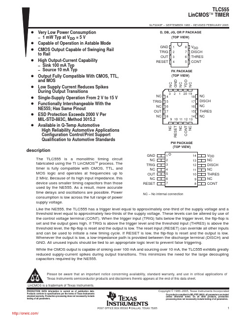
Like the NE555, the TLC555 has a trigger level equal to approximately one-third of the supply voltage and a threshold level equal to approximately two-thirds of the supply voltage. These levels can be altered by use of the control voltage terminal (CONT). When the trigger input (TRIG) falls below the trigger level, the flip-flop is set and the output goes high. If TRIG is above the trigger level and the threshold input (THRES) is above the threshold level, the flip-flop is reset and the output is low. The reset input (RESET) can override all other inputs and can be used to initiate a new timing cycle. If RESET is low, the flip-flop is reset and the output is low. Whenever the output is low, a low-impedance path is provided between the discharge terminal (DISCH) and GND. All unused inputs should be tied to an appropriate logic level to prevent false triggering. While the CMOS output is capable of sinking over 100 mA and sourcing over 10 mA, the TLC555 exhibits greatly reduced supply-current spikes during output transitions. This minimizes the need for the large decoupling capacitors required by the NE555.
查询TLC555CDB供应商
TLC555 LinCMOS TIMER
SLFS043F − SEPTEMBER 1983 − REVISED FEBRUARY 2005
D Very Low Power Consumption D D D D D D D D D
− 1 mW Typ at VDD = 5 V Capable of Operation in Astable Mode CMOS Output Capable of Swinging Rail to Rail High Output-Current Capability − Sink 100 mA Typ − Source 10 mA Typ Output Fully Compatible With CMOS, TTL, and MOS Low Supply Current Reduces Spikes During Output Transitions Single-Supply Operation From 2 V to 15 V Functionally Interchangeable With the NE555; Has Same Pinout ESD Protection Exceeds 2000 V Per MIL-STD-883C, Method 3015.2 Available in Q-Temp Automotive High Reliability Automotive Applications Configuration Control/Print Support Qualification to Automotive Standards
D, DB, JG, OR P PACKAGE (TOP VIEW)
GND TRIG OUT RESET
1 2 3 4
8 7 6 5
VDD DISCH THRES CONT
FK PACKAGE (TOP VIEW)
NC TRIG NC OUT NC
4 5 6 7 8
3 2 1 20 19 18 17 16 15 14 9 10 11 12 13
NC GND NC VDD NC NC DISCH NC THRES NC NC RESET NC
PW PACKAGE (TOP VIEW)
description
The TLC555 is a monolithic timing circuit fabricated using the TI LinCMOS process. The timer is fully compatible with CMOS, TTL, and MOS logic and operates at frequencies up to 2 MHz. Because of its high input impedance, this device uses smaller timing capacitors than those used by the NE555. As a result, more accurate time delays and oscillations are possible. Power consumption is low across the full range of power supply voltage.
AVAILABLE OPTIONS† PACKAGED DEVICES TA 0°C to 70°C −40°C to 85°C −40°C to 125°C VDD RANGE 2 V to 15 V 3 V to 15 V 5 V to 15 V SMALL OUTLINE (D)‡ TLC555CD TLC555ID TLC555QD SSOP (DB)‡ TLC555CDB — — CHIP CARRIER (FK) — — — CERAMIC DIP (JG) — — — PLASTIC DIP (P) TLC555CP TLC555IP — TSSOP (PW)‡ TLC555CPW — —
