P1C1S30
常用钢铁牌号对照表2

抗拉強度35kgf/m㎡之零件 鋼板) 抗拉強度38kgf/m㎡之零件 抗拉強度40kgf/m㎡之零件 抗拉強度45kgf/m㎡之零件 抗拉強度50kgf/m㎡之零件 抗拉強度55kgf/m㎡之零件
抗拉強度60kgf/m㎡之零件 一般用(析出強化鋼) 抗拉強度60kgf/m㎡之零件 低降伏比型鋼板(DP鋼)
P: 高深
核准
审核
作成
MJSH270C MJSH270D MJSH270E MJSH310W MJSH370J MJSH440J
SPHCM SPHDM SPHEM SAPH310M (SAPH370M) SAPH400M SAPH440M
一般部品用鋼板 引伸部品用鋼板 深引伸部品用鋼板 厚板高張力零件(32kgf/m㎡) 厚板高張力零件(38kgf/m㎡) 厚板高張力零件(41kgf/m㎡) 厚板高張力零件(45kgf/m㎡) 厚板高張力零件(50kgf/m㎡) 厚板高張力零件(55kgf/m㎡) 厚板高張力零件(55kgf/m㎡)
耐腐蝕又需高張力零件 與SPCC相當之防鏽零件 與SPCC相當之防鏽零件 與SPCD相當之防鏽零件
SGCC(Z~) SGCC(Z~)
SGCD1 (Z~) SGCD2 (Z~) SGCD3 (Z~) SGHC(Z~) SGCC(F~)
SP709 SP701 SP702
溶 融 鍍 鋅 / 鋅 鐵 合 金 鋼 板
(SP153-590Z)
丰田 (TOYOTA) SPC270C SPC270D SPC270E SPC270F
SPC340 SPC340HR
本田 (HES) JSC270C JSC270D JSC270E JSC270F JSC260G CF340R
三菱 马自达 (MIZIBISHI (MES) ) MJSC270D MJSC270D MJSC270D MJSC270E MJSC270E
浙江威士特-AMDP-□ C1 系列电动机保护器使用手册说明书
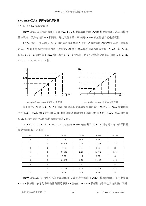
6.9、AMDP-□/C1 系列电动机保护器6.9.1、4-20mA模拟量输出AMDP-□/C1 系列保护器配有3路与A、B、C相电流成比例的4-20mA模拟量输出,这3路模拟量与采集、保护电路及DSP相隔离,通过设置参数C可改变4-20mA模拟量表示的电流范围。
4-20mA输出,表示的A、B、C相电流范围由参数C设置,C参数值以C4C3C2C1四位十进制数表示, C4是C参数右边数第四位十进制数,C4是4-20mA输出电流范围设置位,C4 = 0、1、2、3、4、5、6、7、8,对应的4-20mA输出表示A、B、C相电流分别是电动机保护器额定值的1、1.5、2、2.5、3、3.5、4、4.5、5倍。
0.C4=0对应的4-20mA表示的电流范围 C4=2对应的4-20mA表示的电流范围在上图中,I1表示A、B、C相电流(电动机保护器额定值的倍数),I2表示4-20mA模拟量输出值(mA)。
C4=0,20mA对应的A、B、C相电流是电动机保护器额定值的1倍;C4=2,20mA对应的A、B、C相电流是电动机保护器额定值的2倍。
C4 = 0、1、2、3、4、5、6、7、8,对应的4-20mA输出表示A、B、C相电流(电动机保护器额定值的倍数)如下表。
C4 4 mA 8 mA 12 mA 16 mA 20 mA0 0 0.25 0.5 0.75 11 0 0.375 0.75 1.125 1.52 0 0.5 1 1.5 23 0 0.625 1.25 1.875 2.54 0 0.75 1.5 2.25 35 0 0.875 1.75 2.625 3.56 0 1 2 3 47 0 1.125 2.25 3.375 4.58 0 1.25 2.5 3.75 5AMDP-□/C11□ 系列电动机保护器还配有1路零序电流的4-20mA模拟量输出,零序电流的4-20mA模拟量,表示的零序电流范围是不受C4影响的。
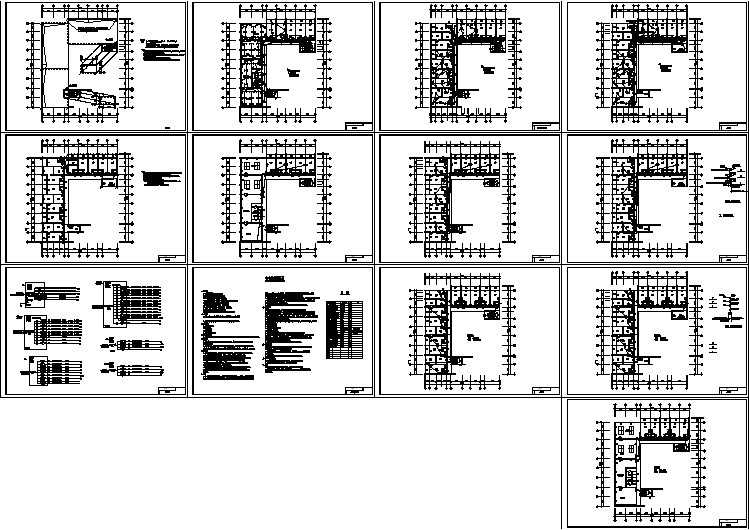
某国企员工宿舍电气设计图纸(13张)
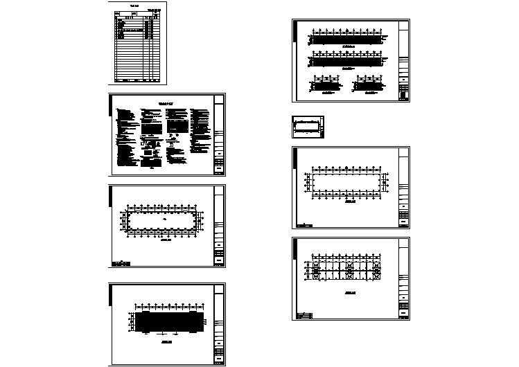
某公司1号钢结构厂房建筑结构CAD图纸
施耐德XUSL..WC 1 XUSL.. .WH类型2和类型4安全光幕.外壳,快速指南

接线图尺寸WH: 白色BK: 黑色BN: 棕色GN: 绿色YE: 黄色GY: 灰色PK: 粉红色BU: 蓝色RD: 红色VT: 紫色TRmm in.32012.6047018.5062024.4177030.3192036.22107042.13122048.03137053.94152059.84167065.7576029.92106041.73116045.67290440590 740890104011901340149016407301030113011.4217.3223.2329.1335.0440.9446.8552.7658.6664.5728.7440.5544.49XUSL p E A BC (± 3 mm)Dppp 016ppp 031ppp 046ppp 061ppp 076ppp 091ppp 106ppp 121ppp 136ppp 1512B 3B 4B 315465615 7659151065121513651515166575510551155 12.418.3124.2130.1236.0241.9347.8353.7459.6565.5529.7241.5345.47337487637 7879371087123713871537168777710771177 13.2719.1725.0830.9836.8942.848.754.6160.5166.4130.5942.446.34182071.65197077.561790194070.4776.38ppp 166ppp 1811815196571.4677.361837198772.3278.23762.99562.2752.95BDA C Ø = 5,8 mm (max.)Ø = 0.23 in. (max.)461.8126±11.04±0.4R U NT E S TE R R缆线颜色描述OSSD1K1_K2 反馈/重启Configuration_B0 Vdc FEOSSD2WH BU BN GN PK 0 V (加热系统)24 V a / c (加热系统)VTBK GY YE RD WH BU BN GN PK GY YE RD+ 24 Vdc Configuration_A 无加热系统带有加热系统缆线颜色描述+ 24 VdcFE0 V (加热系统)24 V a / c (加热系统)-0 VdcBN BN RD WH WH BU BU YE GY GYGN PK Configuration_0Configuration_1无加热系统带有加热系统BK 0 Vdc +24 Vdc12345FE 0 Vdc+24 Vdc Conf. 0Conf. 1XUSL ppp TBN WH BUGY BK0 Vdc +24 Vdc12345FE 0 Vdc+24 Vdc Conf. 0Conf. 1XUSL ppp TBN WH BUGY BK0 Vdc +24 Vdc12345678FE 0 Vdc+24 Vdc Conf._AK1_K2Feedback_Restart Conf._B OSSD1OSSD2XUSL ppp RBN GNGY WH BUYERD PK 0 Vdc +24 Vdc12345678FE 0 Vdc+24 Vdc Conf._AK1_K2Feedback_RestartConf._B OSSD1OSSD2XUSL ppp RRESTARTBN GN GYWH BUYE RD PK 12345678FE 0 Vdc+24 VdcConf._A K1_K2Feedback_RestartConf._B OSSD1OSSD2XUSL pppRRESTARTK2K10 Vdc +24 VdcBNGNGY WH BUYERDPK 0 Vdc +24 VdcK2K112345678FE 0 Vdc+24 Vdc Conf._AK1_K2Feedback_RestartConf._B OSSD1OSSD2XUSL ppp RBN GN GYWH BUYE RD PK 不遵守这些说明可能会导致人员死亡、严重伤害或设备损坏。
习题解析控制工程

60°
45°
(3)
0
[s]
Re
2024/9/30
n=2s-1
20
Im
[s]
3.13
0
Re
0<<1
Im [s]
0
Re
-1<<0
2024/9/30
Im
[s]
0
Re
=1
Im [s]
0
Re
=-1
21
3.14
Gs
s2
9 s
9
s2
2
32 1
3s
32
6
n 31 /
0.167
s
M p 58.8%
t p 1.06s
xo t 10 t 0.1 0.1e10t
单位阶跃响应: (上式旳一阶导数)
xou t 10 1 e10t
单位脉冲响应:
(上式旳二阶导数或xou(t)旳一阶导数)
xoi t 100e10t
2024/9/30
8
系统旳闭环传递函数为:
3.8
GB
s
1
K 0G s K1Gs
15
3.11 内部局部闭环传递函数:
GB1s
s
2 n
2n
K
f n2
整个系统旳闭环传递函数:
GB
s
1
1 s
GB1s
1 s
GB1
s
s2
2 n
2 n
K
f
2 n
s
2 n
2024/9/30
16
GB s s2
n2
2 n
K
f
2 n
s
各国常用钢材牌号对照表

55 0Cr18Ni11Nb 56 Y1Cr18Ni9 1Cr18Ni12 57 (1Cr18Ni12Ti) 0Cr19Ni11 58 (00Cr18Ni10) 59 0Cr18Ni9Cu3 60 0Cr17Ni12Mo2 61 62 0Cr18Ni12Mo2Ti 63 00Cr17Ni13Mo2N 64 65 0Cr18Ni12M3Ti 66 00Cr17Ni14Mo2 67 00Cr19Ni13Mo3 68 69 1Cr18Ni9Ti 70 0Cr23Ni13 2Cr23Ni13 71 (1Cr23Ni13) 0Cr25Ni20 72 (1Cr25Ni20Si2) 2Cr25Ni20 73 (1Cr25Ni20Si2) 74 75 76 77 78 79 80 81 82 83
Steel number of each country comparing table
No. 1 2 3 4 5 6 7 中國 (CHINA) GB Q195(A1,B1) Q215A Q235A Q235B Q235C Q235D (A3,C3) 德國(Germany) DIN S185(St33) UST 34-2 S235JR S235JRG1 S235JRG2 (ST 37-2,UST 37-2,RST 37-2) QSt36-3(C11C) USt4 C10 Ck10 C15 Ck15 C22E Ck22 C25E Ck25 C30E Ck30 C35E Ck35 C40E Ck40 C45E Ck45 C50E Ck53 C55E Ck55 C60E Ck60 Ck67 CK75 16MnCr5 9S20 W-Nr 1.0035 1.0028 1.0037 1.0036 1.0038 法國(France) NF S185(A33) A34 S235JR S235JRG1 S235JRG2 (E24-2, E24-2NE) XC10 FB10 FR10 C10 XC10 C12 XC15 C22E XC18 C25E XC25 C30E XC32 C35E XC38 C4E XC42 C45E XC48 C50E C55E XC55 C60E XC60 XC65 16MC5 國際標准化組織(International 日本(Japan) standard) 俄羅斯(Russia) ISO TOCT JIS CT.1KII HR2 CT.1CII CT.1IIC SS330 HR1 CT.2KII-2,-3 (SS34) Fe 360A SS400 CT.3KII-2 (SS41) Fe 360D CT.3KII-3 CT.3KII-4 BCT.3KII-2 CC8A (A2A1) C25E4 C30E4 C35E4 C40E4 C45E4 C50E4 C55E4 C60E4 SL,SM 9S20 瑞典(Sweden英國 ) (Britain) SS BS 1370 1311 1312 S185 (040A10) 040A12 美國(USA) UNS ASTM K02501 K02502 備注 Remarks
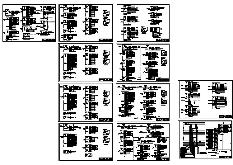
宾馆电路系统设计全套cad图纸
SMA Sunny Tripower 15000TL 20000TL 25000TL 商品说明书

SUNNY TRIPOWER15000TL / 20000TL / 25000TLS T P 15000T L -30 / S T P 20000T L -30 / S T P 25000T L -30Efficient• Maximum efficiency of 98.4%• Yield increase without installation effort due to integrated shade management SMA ShadeFixFlexible• DC input voltage of up to 1000 V • Multistring capability for optimum system design • Optional displayInnovative• Cutting-edge grid management func-tions with Integrated Plant Control • Reactive power available 24/7 (Q on Demand 24/7)Safe• DC surge arrester (SPD type II) can be integratedSUNNY TRIPOWER 15000TL / 20000TL / 25000TLThe versatile specialist for large-scale commercial plants and solar power plantsThe Sunny Tripower is the ideal inverter for large-scale commercial and industrial plants. Not only does it deliver extraordinary high yields with an efficiency of 98.4%, but it also offers enormous design flexibility and compatibility with many PV modules thanks to its multistring capabilities and wide input voltage range.The future is now: the Sunny Tripower comes with cutting-edge grid management functions such as Integrated Plant Control, which allows the inverter to regulate reactive power at the point of common coupling. Separate con-trollers are no longer needed, lowering system costs. Another new feature—reactive power provision on demand (Q on Demand 24/7).Intelligent service with SMA Smart ConnectedSMA SMART CONNECTEDThe integrated service for ease and comfort SMA Smart Connected* is the free monitoring of the inverter via the SMA Sunny Portal. If there is an inverter fault, SMA proactively informs the PV system operator and the installer. This saves valuable working time and costs.With SMA Smart Connected, the installer benefits from rapid diagnoses by SMA. They can thus quickly rectify the fault and score points with the customer thanks to the attraction of additional services.* Details: see document “Description of Services – SMA SMART CONNECTED”AccessoryRS485 interface DM-485CB-10DC surge arrester Typ II, inputs A and B DCSPD KIT3-10Power Control Module PWCMOD-10Multifunction relay MFR01-10● Standard features ○ Optional features — Not available Data at nominal conditions Status: 03/2020Technical DataSunny Tripower15000TL Sunny Tripower 20000TL Sunny Tripower 25000TLInput (DC)Max. generator power 27000 Wp 36000 Wp 45000 Wp DC rated power 15330 W 20440 W 25550 W Max. input voltage1000 V1000 V 1000 VMPP voltage range / rated input voltage 240 V to 800 V / 600 V 320 V to 800 V / 600 V 390 V to 800 V / 600 VMin. input voltage / start input voltage 150 V / 188 V 150 V / 188 V 150 V / 188 V Max. input current input A / input B33 A / 33 A 33 A / 33 A 33 A / 33 A Number of independent MPP inputs / strings per MPP input 2 / A:3; B:3 2 / A:3; B:3 2 / A:3; B:3Output (AC)Rated power (at 230 V, 50 Hz)15000 W 20000 W 25000 WMax. AC apparent power 15000 VA20000 VA 25000 VAAC nominal voltage 3 / N / PE; 220 V / 380 V 3 / N / PE; 230 V / 400 V 3 / N / PE; 240 V / 415 VAC voltage range180 V to 280 V AC grid frequency / range50 Hz / 44 Hz to 55 Hz 60 Hz / 54 Hz to 65 HzRated power frequency / rated grid voltage 50 Hz / 230 VMax. output current / Rated output current29 A / 21.7 A 29 A / 29 A 36.2 A / 36.2 APower factor at rated power / Adjustable displacement power factor 1 / 0 overexcited to 0 underexcitedTHD≤ 3%Feed-in phases / connection phases 3 / 3Effi ciency Max. effi ciency / European Effi ciency 98.4% / 98.0%98.4% / 98.0%98.3% / 98.1%Protective devicesDC-side disconnection device●Ground fault monitoring / grid monitoring ● / ●DC surge arrester (Type II) can be integrated○DC reverse polarity protection / AC short-circuit current capability / galvanically isolated ● / ● / —All-pole sensitive residual-current monitoring unit●Protection class (according to IEC 62109-1) / overvoltage category (according to IEC 62109-1)I / AC: III; DC: IIGeneral dataDimensions (W / H / D)661 / 682 / 264 mm (26.0 / 26.9 / 10.4 inch)Weight61 kg (134.48 lb)Operating temperature range −25 °C to +60 °C (−13 °F to +140 °F)Noise emission (typical)51 dB(A)Self-consumption (at night) 1 WTopology / cooling conceptTransformerless / OpticoolDegree of protection (as per IEC 60529)IP65Climatic category (according to IEC 60721-3-4)4K4H Maximum permissible value for relative humidity (non-condensing)100%Features / function / Accessories DC connection / AC connection SUNCLIX / spring-cage terminalDisplay○Interface: RS485, Speedwire/Webconnect○ / ●Data interface: SMA Modbus / SunSpec Modbus ● / ●Multifunction relay / Power Control Module○ / ○Shade management SMA ShadeFix / Integrated Plant Control / Q on Demand 24/7● / ● / ●Off-Grid capable / SMA Fuel Save Controller compatible ● / ●Guarantee: 5 / 10 / 15 / 20 years ● / ○ / ○ / ○Certifi cates and permits (more available on request)* D oes not apply to all national appendices of EN 50438AS 4777, BDEW 2008, C10/11, CE, CEI 0-16, CEI 0-21, CNS 15382, CNS 15426, DEWA 2.0, DK1, DK2, EN 50549-1, EN 50549-2, G99/1, EN 50438:2013*, IEC 60068-2-x, IEC 61727, IEC 62109-1/2, IEC 62116, IS 16221-1/2, IS 16169, MEA 2013, NBR 16149, NEN EN 50438, NRS 097-2-1, PEA 2013, NTS, PPC, RD 1699/413, RD 661/2007, Res. n°7:2013, RfG compliant,SI4777, TOR generator, UTE C15-712-1, VDE 0126-1-1, VDE-AR-N 4105, VDE-AR-N 4110,VFR 2014Type designationSTP 15000TL-30STP 20000TL-30STP 25000TL-30SMA Solar Technology S T P 15-25T L -30-D S -e n -40 S M A a n d S u n n y T r i p o w e r a r e r e g i s t e r e d t r a d e m a r k s o f S M A S o l a r T e c h n o l o g y A G . S U N C L I X i s a r e g i s t e r e d t r a d e m a r k o f P H O E N I X C O N T A C T G m b H & C o . K G . P r i n t e d o n F S C p a p e r . A l l p r o d u c t s a n d s e r v i c e s d e s c r i b e d a n d a l l t e c h n i c a l d a t a a r e s u b j e c t t o c h a n g e , e v e n f o r r e a s o n s o f c o u n t r y -s p e c i f i c d e v i a t i o n s , a t a n y t i m e w i t h o u t n o t i c e . S M A a s s u m e s n o l i a b i l i t y f o r t y p o g r a p h i c a l a n d o t h e r e r r o r s . F o r t h e l a t e s t i n f o r m a t i o n , p l e a s e v i s i t w w w .S M A -S o l a r .c o m .Professional PV system monitoring, management and data display。
希罗斯水晶微型防水插座Series HR30说明书

HR30-6JA-6P(71)HR30-6R-3P(71)HR30-6R-6P(71)HR30-6R-6S(71)HR30-6R-6SD(71) HR30-7J-12P(71)HR30-7P-12S(71)HR30-7P-12SC(71HR30-8P-12P(71)HR30-8P-12PC(71)Fig.31Miniature Waterproof Plastic ConnectorsHR30 SeriesFeatures1. Small-size with low profile3, 6 contacts:M aximum outer diameter Ø12.6mm Mated length 32.3mm (from the panel surface)10, 12 contacts: M aximum outer diameter Ø15.5mmMated length 42.1mm (from the panel surface)These small, compact connectors offer unique features available only from Hirose.2. Waterproof constructionIP67 and 68 waterproof construction in the mated state IP67: Left submerged in water at a depth of 1m for 30 minutes IP68: Left submerged in water at a depth of 2m for 14 days3. Push/pull lockWaterproof connectors feature an easy to operate push/pull locks developed with our exclusive technology.4. Light weight3 and 6 contacts: 6g (plug + receptacle)10 and 12 contacts: 9g (plug + receptacle)5. C lamp structureO ur proprietary clamping method allows clamping the cable by simply tightening the cord ring.6. Easy mating operationThe plug can be securely locked while holding it in your hand while mating. (Fig.2)7. Mis-insertion preventionMating portions are polarized to avoid improper mating and connector damage.8. Mating markBoth the plug and the r eceptacle featur e a white index mar k on them which is used to quickly align the two interfaces for proper mating.(Fig.3)9. Complies with the RoHS requirementsIn consider ation of envir onmental issues, we use only materials that comply with the RoHS Directive.Push-pull- single action lockØ15.542.1Ø12.632.33 and 6 pos.10 and 12 pos.Mated dimensionsLock/release operationAlignment marksPolarized interfacePush-pull locking collarFig.1Fig.22015.8eHR30 Series●Miniature Waterproof Plastic ConnectorsProduct SpecifiMaterial / FinishProduct Number StructureHR30 - 6 P A - 6 S C (* *)q w e r t y u i23HR30 Series ●Miniature Waterproof Plastic ConnectorsPlugsCrimp TypeSolder TypeØ15.5A(Fully tightened)Applicablecable diameterBA(Fully tightened)Applicablecable diameterHR30-7P-12SC (71)(Representative example)(Representative example)Shown with contacts installed.HR30-6P-6S (71)4HR30 Series ●Miniature Waterproof Plastic ConnectorsPlug for overmoldsCrimp TypeSolder Type25.9Ø15.5Ø6.4AØBØCHR30-8PB-12PCHR30-6PB-6S5HR30 Series ●Miniature Waterproof Plastic ConnectorsReceptaclesSolder TypeGasketBCADE(Thread)F(Hex nut)123456HR30-6R-6P (71)Through hole TypeHR30-8R-12SD (71)DC A B2Through hole post (0.2∞0.5)E F(Hex nut)GasketCrimp TypeØ11.5Ø1515.59.3GasketM11X1(Thread)13(Hex nut)HR30-7R-12PC (71)Shown with contacts installed.(Representative example)(Representative example)(Representative example)6HR30 Series ●Miniature Waterproof Plastic ConnectorsJacksCrimp TypeSolder Type37.3Ø15(Fully tightened)Applicablecable diameterB(Fully tightened)AApplicablecable diameterHR30-7J-12PC (71)HR30-6J-6P (71)Shown with contacts installed.(Representative example)(Representative example)7HR30 Series ●Miniature Waterproof Plastic ConnectorsJack for overmoldsCrimp TypeSolder TypeØ1523.7Ø6.4ABCHR30-6JB-6PHR30-8JB-12SC8HR30 Series ●Miniature Waterproof Plastic ConnectorsNote :W hen using these caps, do not use the gasket that is normally supplied with the receptacle. The “B” diameter end of the receptacle cap will serve as the gasket.CapsFor ReceptacleFor Plugs 1.40.9ØECØAØBØD11.4CØAØBØDØEHR30-6R-C (71)HR30-6P-C (71)(Representative example)(Representative example)9HR30 Series ●Miniature Waterproof Plastic ConnectorsNote : Use wire size 26 to 30 AWG with a jacket diameter of 1 mm max.Crimp ContactsDiagrams of Connectors in Combination0.82111.151.2A-A cross-sectionAA0.8211AAPlugsHR30-*P-**(71)Caps for Plug HR30-*P-C (71)Receptacles HR30-*R-**(71)JacksHR30-*J-**(71)Caps for Receptacle HR30-*R-C (71)Cap mounting diagramCableCapCapPanelMale contactFemale contactNote 1:P lease use connectors with compatible shell size and number of contacts. If you are using a male contact plug, please also use a corresponding product with a female receptacle and a jack.Note 2:P lease install the applicable crimping contacts when using the crimping style connectors. (Please refer to the manual for wiring work.)Note 3:W hen using the cap on the receptacle side, do not use the gasket that is normally supplied with the receptacle. The Hirose cap has the necessary gasket as part of the cap unit.(Representative example)(Representative example)HR30 Series●Miniature Waterproof Plastic ConnectorsSolder termination fixtureBack shell tightening collar HR30-6P-6S-T01HR30-6R-6P-T01HR30-6P-T02 Applicable ToolsCable Assembly ToolsNote : W iring for soldering or disassembly and assembly of plugs and jacks can be accomplishedmore effi ciently when using the cable assembly tool.Tightening collar for back shellNote: T he code ring tightening collar is used to tighten the cord ring to the specifi ed torque.(Please refer to the manual for assembly procedures.)1011HR30 Series ●Miniature Waterproof Plastic ConnectorsContact Position ArrangementPanel CutoutRemarks: 1. The contact arrangement depicts a view from the wiring side. 2. I nstallation is accomplished by securing the receptacle from the back side of the panel using the supplied hexagonnut. The tightening torque of the hexagon nut should be 0.5 N·m for 3, 6 contacts, and 0.8 N·m for 10, 12 contacts.In addition, in order to prevent loosening, please apply Locktight 263 and Lockprimer 7649 manufactured by Henkel Japan Ltd., Tokyo.12312345661234512456789101211312456789101211312345678910HR30-7P-10SC (71)HR30-7P-12SC (71)HR30-8P-12PC (71)HR30-6P-6P (71)HR30-6P-6S (71)HR30-6P-3S (71)Alignment markAlignment markB+0.05A +0.05 0D +0.05ØC+0.05Receptacle, Board Mounting Through Hole PatternRemark: 1. T he receptacle through hole confi guration depicts a view from the mating side of the connector. 2.The above Δ mark indicates the guide key position. 3.The recommended board maximum thickness :1.2mm. 4. T olerance of +0.03mm is recommended for the plated through hole location. Tolerance of +0.02mm is recommendedfor the plated through hole diameter.7R-12PD8R-12SD6R-6SD 1542630.90.91.521.520.491.351.66-Ø0.656R-6PD 1.561.560.90.91.81.86-Ø0.651234560.90.9Applicable ToolsHR30 Series●Miniature Waterproof Plastic ConnectorsAssembly Procedures12HR30 Series●Miniature Waterproof Plastic Connectors1314HR30 Series ●Miniature Waterproof Plastic ConnectorsPoints to note when using Heat shrink tubingWe recommend that you use shrink tubing over the solder connections in order to protect the soldered wires and to enhance insulation. However, please be careful when applying heat in this area when installing the shrink tube so excess heat does not bleed into or affect the resin parts as shown in the figure below.If the product does become heated beyond the area shown and into the resin parts, please make sure to prevent the following.q D eformation of the C ring. This could result in prevention of locking during mating.wM elting of some parts.To prevent the deformation of the C rings of the receptacles and the jack, we recommend heat to be applied after mating with a compatible plug.C ringShrinkable tubeHeat application area ReceptacleCompatible plugHeat application areaMated dimensionsReceptacleHR30 Series●Miniature Waterproof Plastic Connectors General usage notesPrecautions1. M ake sure the power is off before mating or un-mating the connector.2. W hen mating the connector, push it on with a force of a least 30N.After mating, pull slightly on the connector to check for proper mating and to ensure the connector is fi rmly locked to the receptacle.3. A fter mating the connector, do not apply a force over 30N to the cable in the directions shown by the arrows. Anexcessive load can lead to connector damage.30N max.Panel30N max.30N max.4. T o maintain the waterproof performance, cable clamping force and cable stability, please use a cable within therecommended for cable diameters.Because the performance will differ depending on the cable structure, make sure to check all specifi cations of the cable assembly before use or production.5. P lease assemble and install the connector and components with the specifi ed tightening torque.If the tightening torque is too weak or too strong, loosening or breakage can occur.6.Please contact Hirose if your application requires compliance with the Electrical Appliance and Meterial Safety Act.1516HR30 Series ●Miniature Waterproof Plastic ConnectorsThe characteristics and the specifications contained herein are for reference purpose. Please refer to the latest customer drawings prior to use.The contents of this catalog are current as of date of 08/2015. Contents are subject to change without notice for the purpose of improvements.2-6-3,Nakagawa Chuoh,Tsuzuki-Ku,Yokohama-Shi 224-8540,JAPAN TEL: +81-45-620-3526 Fax: +81-45-591-3726USA:HIROSE ELECTRIC (U.S.A.), INC. SAN JOSE OFFICE 3255 Scott Boulevard, Building 7, Suite 101 Santa Clara, CA 95054Phone : +1-408-253-9640Fax : +1-408-253-9641/us/USA:HIROSE ELECTRIC (U.S.A.), INC. CHICAGO OFFICE 580 Waters Edge Lane, Suite 205 Lombard IL 60148Phone : +1-630-282-6701Mail:********************/us/USA:HIROSE ELECTRIC (U.S.A.), INC. HEADQUARTERS 2688 Westhills Court, Simi Valley, CA 93065-6235Phone : +1-805-522-7958Fax : +1-805-522-3217/us/CHINA:HIROSE ELECTRIC (SHANGHAI) CO.,LTD. BEIJING BRANCH A1001, Ocean International Center, Building 56# East 4th Ring Middle Road, ChaoYang District, Beijing, 100025Phone : +86-10-5165-9332Fax : +86-10-5908-1381/cn/TAIWAN:HIROSE ELECTRIC TAIWAN CO., LTD.103 8F, No.87, Zhengzhou Rd., Taipei Phone : +886-2-2555-7377Fax : +886-2-2555-7350 /tw/GERMANY:HIROSE ELECTRIC EUROPE B.V. GERMAN BRANCH Herzog-Carl-Strasse 4 D-73760 Ostfildern (Scharnhauser Park)Phone : +49-711-4560-02-1Fax : +49-711-4560-02-299/eu/GERMANY:HIROSE ELECTRIC EUROPE B.V. NUERNBERG OFFICE Muggenhofer Str. 136 90429 Nuernberg Phone : +49-911 32 68 89 63Fax : +49-911 32 68 89 69/eu/THE NETHERLANDS:HIROSE ELECTRIC EUROPE B.V.Hogehillweg #8 1101 CC Amsterdam Z-O Phone : +31-20-6557460 Fax : +31-20-6557469/eu/GERMANY:HIROSE ELECTRIC EUROPE B.V. HANOVER OFFICE Bayernstr. 3, Haus C 30855 Langenhagen, Germany Phone : +49-511 97 82 61 30Fax : +49-511 97 82 61 35/eu/USA:HIROSE ELECTRIC (U.S.A.), INC. DETROIT OFFICE (AUTOMOTIVE)17197 N. Laurel Park Drive, Suite 253, Livonia, MI 48152Phone : +1-734-542-9963Fax : +1-734-542-9964/us/FRANCE:HIROSE ELECTRIC EUROPE B.V. PARIS OFFICE Regus La Garenne Colombes,Place de La Belgique, 71 Boulevard National La Garenne Colombes, 92250, France Phone : +33 (0) 1 7082 3170Fax : +33 (1) 7082 3101/eu/UNITED KINGDOM:HIROSE ELECTRIC EUROPE BV (UK BRANCH)4 Newton Court, Kelvin Drive, Knowlhill, Milton Keynes, MK5 8NH Phone : +44-1908 202050Fax : +44-1908 202058/eu/CHINA:HIROSE ELECTRIC (SHANGHAI) CO., LTD.1601, Henderson Metropolitan, NO.300, East Nanjing Road, Huangpu District, Shanghai, China 200001Phone : +86-21-6391-3355Fax : +86-21-6391-3335 /cn/HONG KONG:HIROSE ELECTRIC HONGKONG TRADING CO., LTD.Room 1001, West Wing, Tsim Sha Tsui Centre, 66 Mody Road, Tsim Sha Tsui East, Kowloon, Hong Kong Phone : +852-2803-5338 Fax : +852-2591-6560/hk/CHINA:HIROSE ELECTRIC TECHNOLOGIES (SHENZHEN) CO., LTD.Room 09-13, 19/F, Office Tower Shun Hing Square, Di Wang Commercial Centre, 5002 Shen Nan Dong Road, Shenzhen City, Guangdong Province, 518008Phone : +86-755-8207-0851Fax : +86-755-8207-0873/cn/SINGAPORE:HIROSE ELECTRIC SINGAPORE PTE. LTD.10 Anson Road #26-16, International Plaza 079903, SingaporePhone : +65-6324-6113 Fax : +65-6324-6123/sg/KOREA:HIROSE KOREA CO., LTD.250, Huimanggongwon-ro, Siheung-si,Gyeonggi-do, Korea, 429-849Phone : +82-31-496-7000,7124Fax : +82-31-496-7100http://www.hirose.co.kr/INDIA:HIROSE ELECTRIC SINGAPORE PTE. LTD. DELHI LIAISON OFFICE Office NO.519, Regus-Green Boulevard, Level5, Tower C, Sec62, Plot B-9A, Block B, Noida, 201301, Uttar Pradesh, India Phone : +91-12-660-8018Fax : +91-120-4804949/sg/THAILAND:HIROSE ELECTRIC SINGAPORE PTE. LTD. BANGKOK OFFICE (REPRESENTATIVE OFFICE)Unit 4703, 47th FL., 1 Empire Tower, South Sathorn Road, Yannawa, Sathorn, Bangkok 10120 Thailand Phone : +66-2-686-1255Fax : +66-2-686-3433/sg/INDIA:HIROSE ELECTRIC SINGAPORE PTE. LTD. BANGALORE LIAISON OFFICE Unit No-403, 4th Floor, No-84, Barton Centre, Mahatma Gandhi (MG) Road, Bangalore 560 001, Karnataka, India Phone : +91-80-4120 1907Fax : +91-80-4120 9908/sg/MALAYSIA:HIROSE ELECTRIC SINGAPORE PTE. LTD.1-10-07, Suntech @ Penang Cybercity (1164),Lintang Mayang Pasir 3,11950, Bayan Baru, Penang, Malaysia.Phone : +604-619-2564 Fax : +604-619-2574/sg/)HR30-8P-C(71)HR30-PC-111HR30-SC-111HR30-8R-12SD(71)HR30-7R-10PC(71 )HR30-6JA-6P(71)HR30-6R-3P(71)HR30-6R-6P(71)HR30-6R-6S(71)HR30-6R-6SD(71) HR30-7J-12P(71)HR30-7P-12S(71)HR30-7P-12SC(71HR30-8P-12P(71)HR30-8P-12PC(71)。
西门子 SICAM P13 SICAM P15 单相多功能电力仪表 使用说明书
SICAM P13 SICAM P15单相多功能电力仪表使用说明书V1.2概述1技术指标2功能介绍3安装与接线4操作与显示 5 通讯 6 使用与维护7 产品型号和订货号8 售后服务91概述1.1 产品简介SICAM P13 & P15单相电子式多功能监测仪表是一款集测量、计量、LCD显示、通信于一体的电力仪表,可以测量电网电压、电流、有功功率、无功功率、视在功率、功率因数以及频率;并能计量有无功电能。
通信接口支持MODBUS-RTU通信规约。
仪表配有2路开关量输入,可以实现本地或远程的开关信号监测功能。
本仪表广泛适用于变配电自动化系统、工业控制和工业自动化系统、能源管理系统和小区电力监控等场合。
本电能表符合以下标准:GB/T17215.301-2007 多功能电能表特殊要求GB/T17215.322-2008 静止式有功电能表(0.2S级和0.5S级)GB/T17215.323-2008 静止式无功电能表(2级和3级)DL/T614-2007 多功能电能表DL/T645-2007 多功能电能表通信规约Modbus-RTU1.2 产品特点本仪表采用了高精度采样计量单元和高速MCU数据处理单元,可实现高精度宽范围准确计量和快速数据分析;采用段码式多行宽视角液晶显示屏,显示内容很丰富;液晶配备白色背光,可满足黑暗环境下查阅数据的要求;支持RS485通信端口和工业标准通信规约,组网便捷灵活;选配不同通信模块,可满足多种用户的不同接口需求。
2技术指标项目技术指标产品标准GBT18216.12-2010 IEC61557-12:2007接线形式单相测量电压参比电压U n:AC220V、AC100V 测量范围:10V~264V相电压功耗:<0.1 V A(单相@220 V AC) 精度:RMS 0.2 %分辨率:0.01V电流额定电流I n:1A、5A测量范围:0.01 In ~10A最大测量范围:9A功耗:<0.3 V A(单路额定电流@ 5A) 精度:RMS 0.2 %分辨率:0.001A功率(有功、无功、视在) 精度:0.5%分辨率:0.001kW/kVar/kV A电网频率测量范围:45 Hz~65 Hz 精度:0.2%分辨率:0.01 Hz计量有功电能准确度等级:0.5S分辨率:0.01 kWh, 5000imp/kWh 无功电能准确度等级:2级分辨率:0.01 kvarh, 5000imp/kvarh数字信号电能脉冲输出1路有功电能脉冲输出光耦隔离,4000V RMS开关量输入2路干接点输入光耦隔离,4000V RMSRS-485通信口接口类型:两线半双工通信速率:600bps~38400bps规约:Modbus-RTU 和DL/T-645通信工作温度-25℃~+60℃环境极限工作温度-35℃~+70℃相对湿度≤95%(无凝露)工作电源交流或直流电源输入最大范围:40V~420V功耗:≤1W,2V A @220V其它尺寸外形尺寸(mm):72×72×85开孔尺寸(mm):67×67重量约300g防护等级IP513 功能介绍3.1测量功能本仪表可测量单相电压、电流、有功功率、无功功率、视在功率、功率因数和电网频率,以上数据每秒更新一次。
赛米控丹佛斯 SEMITRANS IGBT模块 SKM75GB17E4 数据表
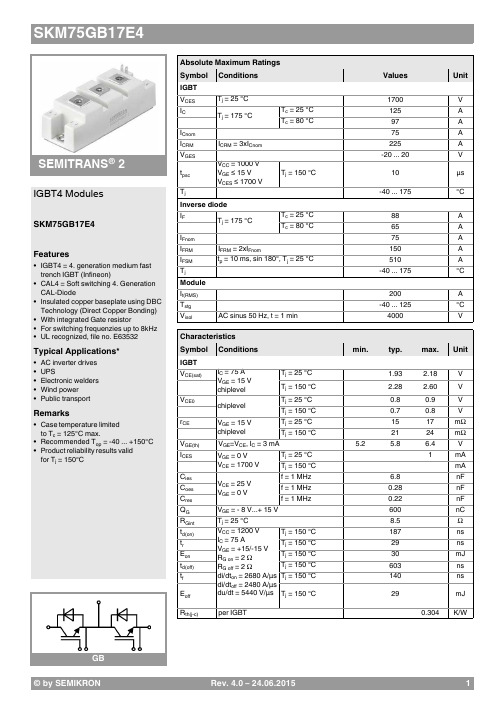
®2IGBT4 ModulesSKM75GB17E4Features•IGBT4 = 4. generation medium fast trench IGBT (Infineon)•CAL4 = Soft switching 4. Generation CAL-Diode•Insulated copper baseplate using DBC Technology (Direct Copper Bonding) •With integrated Gate resistor•For switching frequenzies up to 8kHz •UL recognized, file no. E63532Typical Applications*•AC inverter drives •UPS•Electronic welders •Wind power •Public transportRemarks•Case temperature limited to T c = 125°C max.•Recommended T op = -40 ... +150°C •Product reliability results valid for T j = 150°CAbsolute Maximum Ratings SymbolConditions Values UnitIGBT V CES T j =25°C 1700V I C T j =175°CT c =25°C 125A T c =80°C97A I Cnom 75A I CRMI CRM = 3xI Cnom 225A V GES -20...20V t psc V CC =1000V V GE ≤ 15V V CES ≤ 1700VT j =150°C10µs T j-40 (175)°C Inverse diode I F T j =175°CT c =25°C 88A T c =80°C 65A I Fnom75A I FRM I FRM = 2xI Fnom150A I FSM t p =10ms, sin 180°, T j =25°C510A T j -40...175°C Module I t(RMS)200A T stg -40 (125)°C V isolAC sinus 50 Hz, t =1min4000VCharacteristics SymbolConditions min.typ.max.UnitIGBT V CE(sat)I C =75A V GE =15V chiplevel T j =25°C 1.93 2.18V T j =150°C 2.28 2.60V V CE0chiplevel T j =25°C 0.80.9V T j =150°C 0.70.8V r CE V GE =15V chiplevelT j =25°C 1517m ΩT j =150°C2124m ΩV GE(th)V GE =V CE , I C =3mA 5.25.86.4V I CES V GE =0V V CE =1700V T j =25°C 1mA T j =150°C mA C ies V CE =25V V GE =0Vf =1MHz 6.8nF C oes f =1MHz 0.28nF C res f =1MHz0.22nF Q G V GE =- 8 V...+ 15 V 600nC R Gint T j =25°C 8.5Ωt d(on)V CC =1200V I C =75AV GE =+15/-15V R G on =2ΩR G off =2Ωdi/dt on =2680A/µs di/dt off =2480A/µs du/dt =5440V/µs T j =150°C 187ns t r T j =150°C 29ns E on T j =150°C 30mJ t d(off)T j =150°C 603ns t f T j =150°C 140ns E off T j =150°C 29mJ R th(j-c)per IGBT0.304K/WCharacteristics SymbolConditionsmin.typ.max.UnitInverse diodeV F = V EC I F =75AV GE =0V chiplevelT j =25°C 2.00 2.40V T j =150°C 2.14 2.56V V F0chiplevel T j =25°C 1.32 1.56V T j =150°C 1.08 1.22V r FchiplevelT j =25°C 9.111m ΩT j =150°C1418m ΩI RRM I F =75A di/dt off =2860A/µs V GE =-15VV CC =1200VT j =150°C 95A Q rr T j=150°C27µC E rr T j =150°C 21mJR th(j-c)per diode0.632K/W Module L CE 30nH R CC'+EE'terminal-chip T C =25°C 0.65m ΩT C =125°C1.09m ΩR th(c-s)per module 0.040.05K/W M s to heat sink M635Nm M t to terminals M52.55Nm Nm w160g® 2IGBT4 ModulesSKM75GB17E4Features•IGBT4 = 4. generation medium fast trench IGBT (Infineon)•CAL4 = Soft switching 4. Generation CAL-Diode•Insulated copper baseplate using DBC Technology (Direct Copper Bonding) •With integrated Gate resistor•For switching frequenzies up to 8kHz •UL recognized, file no. E63532Typical Applications*•AC inverter drives •UPS•Electronic welders •Wind power •Public transportRemarks•Case temperature limited to T c = 125°C max.•Recommended T op = -40 ... +150°C •Product reliability results valid for T j = 150°CThis is an electrostatic discharge sensitive device (ESDS), international standard IEC 60747-1, Chapter IX* The specifications of our components may not be considered as an assurance of component characteristics. Components have to be tested for the respective application. Adjustments may be necessary. The use of SEMIKRON products in life support appliances and systems is subject to prior specification and written approval by SEMIKRON. We therefore strongly recommend prior consultation of our staff.。
P1说明书升级内容0930-01s

通电后常亮蓝色灯,开机或休眠后常亮橙色灯。 2. 梯形校正 可以通过遥控器上的梯形校正按键调节屏幕外形:
操作指南
1. 快速设置 1.1 开机
接上电源线,轻按机身或遥控器上的电源按键,稍作等候, 机器会自动完成系统开机启动。 1.2 关机 1.2.1 Android版本
备注
Windows/Android
Windows/Android 第一次按下切换到后置HDMI,
再次按下切换到前置HDMI
Windows:网站主页
Windows/Android Android:系统主页(在HDMI
或VGA 输入环境下可返回到主页)
Windows/Android
Windows:在HDMI或VGA输入
电子教鞭 激光发射器套件
无线键鼠套件 3D眼镜 吊装支架 投影幕布 投影白板
数量(件) 1 1 1 1 1 1 1 1 1 1 1 1 1 1
标配/选配 标配 标配 标配 标配 标配 选配 选配 选配 选配 选配 选配 选配 选配 选配
2.产品示意图 2.1 接口及按键功能介绍
后侧:
HDMI输入 SPDIF
5
3. 焦距调节 如果发现画面字体模糊不清晰,需要通过调焦齿轮进行调节。
转动调焦齿轮进行调节 6
系统配置
功能特性
处理器
四核处理器
操作系统
Android 系统 / Windows 系统
内存
2GB/4GB/8GB
硬盘
16GB/32GB/64GB/128GB/256GB/500GB/1TB
WIFI
支持 802.11 a/b/g/n 无线网络,双频wifi
DMP301C1母联备自投保护测控装置说明书_V1.2.1
5. Qd 无功电度
6. F1 Ⅰ段母线频率(Ua1 相)
7. F2 Ⅱ段母线频率(Ua2 相)
8. Ia、Ib、Ic 母联保护相电流
9. Ua、Ub、Uc 测量相电压
10. Uab、Ubc、Uca 测量线电压
11. Ua1、Ub1、Uc1Ⅰ段a1 Ⅰ段母线线电压
22.U22 Ⅱ段母线负序电压
23.Ua2~Ua11 A 相 2~11 次谐波电压 24.Ia2~Ia11 A 相 2~11 次谐波电流
25.Ux1 进线Ⅰ线路电压
26.Ux2 进线Ⅱ线路电压
27.Ix1 进线Ⅰ线路电流
28.Ix2 进线Ⅱ线路电流
29.In 保护 CT 二次额定电流
30.∠ 角度符号
3 硬件说明............................................................................................................ - 6 3.1 硬件结构................................................................................................. - 6 3.2 交流输入插件......................................................................................... - 6 3.3 CPU 插件................................................................................................ - 7 3.4 操作及继电器出口插件......................................................................... - 8 3.5 电源插件................................................................................................. - 8 3.6 人机接口................................................................................................. - 8 -
汤姆生电缸使用案例

汤姆生电缸使用案例
汤姆生电缸(Thomson Linear Actuators)在许多领域都有广泛的应用,以下是使用汤姆生电缸的一些案例:
1. 工业自动化:在工业自动化生产线中,汤姆生电缸被用于精确控制机器人的运动轨迹和定位,实现高效、精准的生产过程。
2. 医疗器械:由于汤姆生电缸具有高精度、高稳定性和低维护成本等特点,它被广泛应用于医疗器械领域,如手术机器人、诊断设备和康复机器人的驱动系统中。
3. 航空航天:在航空航天领域,汤姆生电缸的高性能和可靠性得到了充分体现,它可以用于控制飞行器的姿态、位置和速度等参数。
4. 能源领域:在风能、太阳能等可再生能源领域,汤姆生电缸作为高效、可靠的驱动系统,能够实现能源设备的精准控制和优化运行。
5. 物流领域:在物流自动化系统中,汤姆生电缸能够实现快速、准确的货物分拣和搬运,提高物流效率。
6. 农业领域:在农业机械装备中,汤姆生电缸可以用于精准控制农业机械的作业深度、速度和方向,提高农业生产效率。
7. 机器人教育:在机器人教育和培训领域,汤姆生电缸作为机器人的驱动部件,能够帮助学生和培训人员更好地理解机器人技术的基本原理和应用。
这些只是汤姆生电缸应用的一部分案例,实际上,只要有需要高精度、高稳定性、低维护成本的直线运动控制的应用场景,汤姆生电缸都可能成为一种理想的解决方案。
水洗可分离安全断电开关 LDS30系列说明书

Non-Fused Safety Disconnect Switch in Watertight/Submersible EnclosureCat. Nos. LDS30-AXC, LDS30-ACC, LDS30-AXS, LDS30-ACS, LDS30-0MB, LDS30-AMBRated: 30/32A-600VAC Max., Aux Contact Rated: 10A, 600Vpowerswitch®WARNINGS• TO AVOID FIRE, SHOCK, OR DEATH: TURN OFF POWER AT CIRCUIT BREAKER OR FUSE AND TEST THAT POWER IS OFF BEFORE REPLACING ENCLOSURE COVER.• T O AVOID FIRE, SHOCK OR DEATH, DISCONNECT ALL POWER SUPPLIES TO ENCLOSURE BEFORE EXPOSING INTERIOR. MORE THAN ONE SUPPLY DISCONNECT MAY BE REQUIRED TO DE-ENERGIZE THIS EQUIPMENT BEFORE SERVICING.• T his enclosure cover assembly includes a lockout provision (in the OFF position) for a suitable padlock. Use up to three (3) padlocks with a shackle diameter of 1/4 in. (6 mm) only to isolate power from the connected equipment in compliance with OSHA Lockout/Tagout Regulation 29 CFR Part 1910.147. NOTE : The lockout feature does NOT interrupt the power supplied to the switch within the enclosure.CAUTIONS• C heck to see that the rating marked on the device is correct for the intended installation. Connected equipment electrical rating must not exceed the ampere rating of this device.• T he device is suitable for use on a circuit capable of delivering not more than 600 VAC maximum. For fused items, use Class J fuses.• T his device must be mounted vertically with the line side at the top.• S uitable as Motor Disconnect on a circuit capable of delivering not more than 10kA rms symmetrical amperes, 600V max., when protected by a 60A Class J fuse.• F or installation only by an electrician in accordance with the National Electrical Code ® (NEC ®) or the Canadian Electrical Code ® (CEC ®), local codes, and the installation instructions.• U se of a UL Listed Watertight conduit fitting (not provided) is required to maintain the desired environmental ratings. Rating of the fitting/hub must be equal to or better than the desired installation ingress protection rating.NOTE: Feed-thru configurations are possible .StatementsCleaning Procedures© 2021 Leviton Mfg. Co., Inc.**- W ire types RHW, THHW, THW, THWN, XHHW, USE, ZW, TBS, SA, SIS, FEP , FEPB, MI,RHH, RHW-2,THHN, THHW, THW-2, THWN-2,USE-2, XHH, XHHW, XHHW-2, ZW-2***- NEC table 250.122 for unit rated ampacities. For other types/styles refer to NEC.FOR CANADA ONLYFor warranty information and/or product returns, residents of Canada should contact Leviton in writing at Leviton Manufacturing of Canada ULC to the attention of the Quality Assurance Department, 165 Hymus Blvd, Pointe-Claire (Quebec), Canada H9R 1E9 or by telephone at 1 800 405-5320.WARNING: RISK OF ELECTRIC SHOCK. TURN OFF POWER AT CIRCUIT BREAKER OR FUSE. DO NOT clean this product while undergoing electrical maintenance or service.CAUTION: Use only chemicals and cleaning solutions that are safe for use with plastics and rubber gaskets.CAUTION: DO NOT direct or concentrate high pressure water or cleaning solution on the enclosure gasket seams, switch handle area or exterior labels.NOTE: Follow general cleaning procedures established by your facility.NOTE: This product is certified by NSF ® International to NSF/ANSI/3-A 14159-1.a. U se hose-directed water or cleaning solution to remove any collected contaminants from behind the enclosure.b.U se hose-directed water or cleaning solution to remove soil and contaminants from the exterior surfaces of the enclosure.c. U se a dry clean cloth to wipe away any excess water.TRADEMARK DISCLAIMERLeviton Mfg. Co., Inc. trademarks: Leviton and the Leviton logo are registered in the US, Canada, Mexico and China; Powerswitch is registered in the US. Use herein of third party trademarks, service marks, trade names, brand names and/or product names are for informational purposes only, are/may be the trademarks of their respective owners; such use is not meant to imply affiliation, sponsorship, or endorsement.LIMITED 3 YEAR PRODUCT WARRANTYFor Leviton’s limited 3 year product warranty, go to . For a printed copy of the warranty you may call 1-800-323-8920 or write to Leviton Manufacturing Co., Inc., Att: Customer Service Dept., 201 North Service Road, Melville, New York 11747.Remote Monitoring Featuresa. F or models with remote monitoring via Wi-Fi connection (LDS30-AXC/LDS30-ACC), refer to the Inform App Manual (document number Q-1216).b. F or models with remote monitoring via Modbus connection (LDS30-0MB/LDS30-AMB), refer to the Inform Modbus Setup Guide.NOTE : These documents are available at .For Technical Assistance Call: 1-800-824-3005 (USA Only) or 1-800-405-5320 (Canada Only) Specifications。
Topeak 30 mm DeFender XC1 安装说明书

INSTALLATIONUser's GuidePlease contact your Topeak dealer with any questions.For USA customer service call : 2-year Warranty: All mechanical components against manufacturer defects only.Warranty Claim RequirementsTo obtain warranty service, you must have your original sales receipt. Items returned without a sales receipt will assume that the warranty begins on the date of manufacture. All warranties will be void if the product is damaged due to user crash, abuse, system alteration, modification, or used in any way not intended as described in this operating manual.30mmDeFender ™ XC1Right Side2.5 mm Allen keyNote : Do not loosen the bolt completely.(Rear)5. Install the front fender legs right on the top of rear fender's properly as shown. Tighten both tension bolts.Prepare to RideM-TC9625-GB 5/12Copyright © Topeak, Inc. 2012Right SideTool required: 2.5 mm Allen keyMax. Tire Dim. : 26"x2.6"1. Use M4 x 12 mm bolts to lock the fender legs on fenders as shown.2. Loosen tension bolt on four fender legs.3. Install the rear fender to the fork legs and DO NOT tighten the tension bolts completely. Place the Indicator Card to the fender and adjust fender to make sure there is at least 30 mm clearance between fender and tire as shown.Assemble Indictor card first then place and align it to the rear fender as shown.4. Make sure the rear fender is aligned with tire. Tighten both tension bolts and remove the Indicator Card.WARRANTY30 mm clearance(Recommended)6. Apply both stickers to fenders properly.GB910111213M4 x 40mm Bolt (Fits ø40~ø48.5 mm)M4 x 25mm Bolt (Fits ø36~ø40 mm )PresetEnd Capx4x4Plastic Washerx4Nutx4x4IMPORTANT NOTE678(F)(R)Sticker x 2pcs (each)2.5 mm Allen keyIndicator Card23451M4 x 12mmBoltFront Legs Rear LegsFrontRear(RR)(FL)(RL)(FR)x2Fits ø36~ø40 mmFits ø40~ø48.5 mm119(Rear)4(RR)(RL)25(Front)35(FR)(FL)112131112131030mm c l ea r a n c e30m m c l e a r a n c eWARNING121. To avoid from hitting the downtube with the rear fender at full fork compression, it is recommended to maintain a 30 mm clearance between the rear fender and tire. Exceeding 30 mm may cause damage to the bike.2. Make sure there is adequate clearance between the fenders and tire width to avoid damaging your bike or fenders.3. Insure properly adjusted fenders after each installation. Make sure there is enough clearance between fenders, tire and downtube.Note: DeFender XC1 has a disengage function that isactivates if a large object enters the wheel. The sticker easily identifies which fender has disengaged from its leg.* The specifications and design are subject to change without notice.IMPORTANT NOTEMax. Tire Dim.: 26"x2.6"A unique design allows front fender to disengage due to any large obstructions entering the wheel.DeFender™XC11Prepare to Ride。
小型直线驱动器

SGDC10-25
31.5 120 (30) 电缆长 500±30 φ4.8
φ9.5 0 -0.01
φ9.5 0 -0.01
M9.5×0.5
(φ10.6)
(φ8.95)
(φ10.6)
PKA ACT
型号
曲 推
(φ8.95)
げ
R3
0
M9.5×0.5
曲 推
げ
R3
0
(13.6)
(13.6) (13.6)
※注意保持直线驱动器和平台运动方向的平行。
F012
系统图
小型直线驱动器用控制器 小型直线驱动器
应用系统
USB
PC
SGDC10-13
USB
光学元件· 薄膜产品 镜架
RS232C
SRC-101
切换开关盒
USB RS232C
加长电缆
USB电缆 RS232C电缆
SGDC10-13F
底座
手动平台
SRC-201
注意
底座
手动平台
驱动装置
需要用到专用的螺纹扳手。 如有不 ▶把手动微分头更换为直线驱动器时, 明之处, 请咨询。 冲击, 压缩, 弯曲, 扭曲或拉伸都是引起断线的原 ▶ 请注意电缆的使用。 因。
自动平台
光源
目录
微分头 差动微分头 精密调节螺杆 小型直线驱动器
外形图
SGDC-10-13/13F
17.5 φ5 A (30) 电缆长 500±30 φ4.8 φ5
2 3 5 2
目录 光源
(φ10.6)
(φ8.95)
USB电缆
SRC
目录编号
W8017
微分头 差动微分头 精密调节螺杆 小型直线驱动器
- 1、下载文档前请自行甄别文档内容的完整性,平台不提供额外的编辑、内容补充、找答案等附加服务。
- 2、"仅部分预览"的文档,不可在线预览部分如存在完整性等问题,可反馈申请退款(可完整预览的文档不适用该条件!)。
- 3、如文档侵犯您的权益,请联系客服反馈,我们会尽快为您处理(人工客服工作时间:9:00-18:30)。
第30节 浅水航行船
A. 总则
1.
除本节中另有规定外,第1节至第22节
的要求也适用于浅水航行船。
2.
对符合本节要求的浅水航行的船,将在其
入级符号后加注附加标志“W ”“S HALLOW W A TER S ERVICE ”。
3.
除非船东要求采用更大的载荷,甲板载荷
应取p = 6 kN/m 2。
B. 外板
1. 船中0.4L 区域内船底板的厚度应不小
于:
H
T
L a a
⋅=0
3
.1t [mm] a 048.0500
+=L
[mm] 2. 对平底船,底板厚度应增加0.5mm 。
3.
船中0.4L 区域内舷侧外板的厚度可比按
1确定的船底板厚度小0.5mm 。
4.
距船长L 的首尾端0.05L 区域内的板厚可
比按1确定的值小1.0mm 。
5. 任何部位的外板厚度均应不小于3.5mm 。
6.
不要求按第6节E 中的规定对船首底部进
行加强。
7.
上层建筑侧壁板的厚度应类似地按4和5
确定。
C. 水密舱壁和液舱舱壁
1.
水密舱壁的尺寸应按第11节确定。
板厚不必大于按船中部的肋骨间距相应的舷侧
板厚度。
但厚度应不小于下列的最小值: 对最低的列板:
t min = 3.5 [mm]
对其余的列板: t min = 3.0 [mm]
2.
液舱舱壁和液舱围壁的尺寸应按第12节
确定。
但板厚和扶强材腹板的厚度应不小于5.0mm 。
D. 甲板开口 1.
舱口
1.1 舱口围板距甲板的高度应不小于: 在位置1的甲板上 - 600 mm
在位置2的甲板上 - 380 mm
另见第1节H.6.3。
1.2
围板的厚度应按下列公式确定:
纵向围板:
6
5.4t
+
= [mm]
横向围板:
2b
75.2t q += [mm]
- 舱口长度[m]; b - 舱口宽度[m]。
1.3 对于舱口盖,第17节C 的要求适用。
2. 舱棚、升降梯口
2.1
机炉舱棚的高度应不小于600mm , 其厚
度应不小于3 mm 。
围板高度应不小于350 mm ,围板厚度应不小于4.0 mm 。
2.2
升降梯口围板距甲板的高度应不小于:
在位置1的甲板上 - 600 mm 在位置2的甲板上 - 380 mm
E. 舾装设备
1.
锚、锚链和推荐缆索的配备应按第18节
确定。
锚的质量可为表18.2所要求值的60%。
锚链直径可根据已减少的锚质量确定。
2.
对于质量小于120kg 的锚,K1级钢锚链
的直径应按下式计算: P 15.1d = [mm]
P
- 锚质量 [kg]。
短链环锚链的破断载荷与有档链环锚链者相同。
3.
如已确定锚的质量小于80 kg ,则仅需配
一个锚,且锚链长度不必超过表18.2要求长度的50%。
4.
建议缆索的长度为表18.21中所列长度的
50%。
5.
其舾装设备符合本节要求的浅水航行船,
将在其登记符号上加注标志“W ”。
1
另见第18节F 。
