2SB1260-Q-TN3-R中文资料
三孔3WL1210型固定安装电路保护器产品说明书
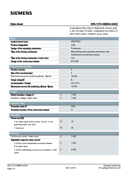
Image database (product images, 2D dimension drawings, 3D models, device circuit diagrams, ...) /bilddb/cax_en.aspx?mlfb=3WL12104BB344AN2
Short-time current resistance (Icw)
● limited to 0.5 s / rated value
kA
● limited to 1 s / rated value
kA
● limited to 2 s / rated value
kA
● limited to 3 s / rated value
2 2
system protection
500
Yes No Yes No
No No
without display
3WL1210-4BB34-4AN2 Page 2/4
05.01.2016
Changes preserved © Copyright Siemens AG
Short circuit
Operational short-circuit current breaking capacity (Ics)
05.01.2016
Changes preserved © Copyright Siemens AG
General Product Approval Shipping Approval
电子电气必备常识
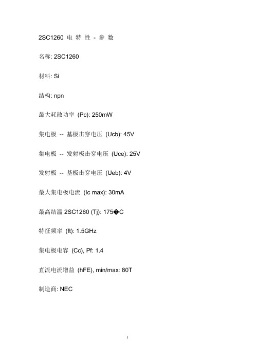
2SC1260 电特性- 参数名称: 2SC1260材料: Si结构: npn最大耗散功率(Pc): 250mW集电极-- 基极击穿电压(Ucb): 45V 集电极-- 发射极击穿电压(Uce): 25V 发射极-- 基极击穿电压(Ueb): 4V最大集电极电流(Ic max): 30mA最高结温 2SC1260 (Tj): 175�C特征频率(ft): 1.5GHz集电极电容(Cc), Pf: 1.4直流电流增益(hFE), min/max: 80T制造商: NEC1.共射极电路当信号与基极偏压同相时,基极电位升高,使基极电流增大,集电极电位降低,集电极负载电流会比基极电流增大量成倍增大;当信号与基极偏压反相时,基极电位降低,使基极电流减小,集电极电位升高,集电极负载电流会比基极电流减小量成倍减小。
集电极电流变化量与三极管放大倍数有关。
共射极电路集电极电位变化方向与基极电位变化方向相反,因此也叫反相器。
信号电流不是直接穿过三极管,只能在基极回路流通,在集电极回路可得到放大的电流信号,这两个回路的公共点是发射极,因此又叫共发射极电路。
共射极电路又称反相放大电路,其特点为电压增益大,输出电压与输入电压反相,低频性能差,适用于低频、和多级放大电路的中间级。
2.共集电极电路共集电极电路又称射极输出器、电压跟随器,其特点是:电压增益小于1而又近似等于1,输出电压与输入电压同相,输入电阻高,输出电阻低,常用于多级放大电路的输入级、输出级或缓冲级。
3 .共基极电路电路特点:输出电压与输入电压同相,输入电阻底,输出电阻高,常用于高频或宽频带电路。
4.反馈是将输出信号的一部分或全部以通过反馈网络送到输入端。
负反馈放大电路有四种不同类型,由瞬时极性判断反馈的性质,由输出端判别电压或电流反馈,由输入端判别串联或并联反馈。
去耦电容在电子电路中,去耦电容和旁路电容都是起到抗干扰的作用,电容所处的位置不同,称呼就不一样了。
BTA12-600中文资料
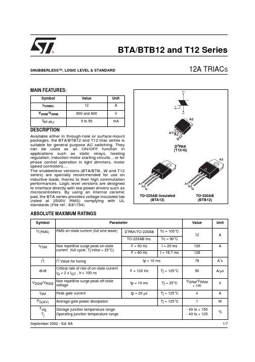
1/7®BTA/BTB12 and T12 SeriesSNUBBERLESS ™, LOGIC LEVEL & STANDARD12A TRIAC SSeptember 2002 - Ed: 6AMAIN FEATURES:DESCRIPTIONAvailable either in through-hole or surface-mount packages, the BTA/BTB12 and T12 triac series is suitable for general purpose AC switching. They can be used as an ON/OFF function in applications such as static relays, heating regulation, induction motor starting circuits... or for phase control operation in light dimmers, motor speed controllers,...The snubberless versions (BTA/BTB...W and T12series) are specially recommended for use on inductive loads, thanks to their high commutation performances. Logic level versions are designed to interface directly with low power drivers such as microcontrollers. By using an internal ceramic pad, the BTA series provides voltage insulated tab (rated at 2500V RMS) complying with UL standards (File ref.: E81734)Symbol Value Unit I T(RMS)12A V DRM /V RRM 600 and 800V I GT (Q 1)5 to 50mAABSOLUTE MAXIMUM RATINGSSymbol ParameterValueUnit I T(RMS)RMS on-state current (full sine wave)D ²PAK/TO-220AB Tc = 105°C 12A TO-220AB Ins.Tc = 90°C I TSM Non repetitive surge peak on-state current (full cycle, Tj initial = 25°C) F = 50 Hz t = 20 ms 120AF = 60 Hzt = 16.7 ms126I ²t I ²t Value for fusingtp = 10 ms78A ²s dI/dtCritical rate of rise of on-state current I G = 2 x I GT , tr ≤ 100 nsF = 120 Hz Tj = 125°C 50A/µs V DSM /V RSM Non repetitive surge peak off-statevoltagetp = 10 ms Tj = 25°C V DRM /V RRM+ 100V I GM Peak gate currenttp = 20 µsTj = 125°C 4A P G(AV)Average gate power dissipation Tj = 125°C1W T stg T jStorage junction temperature range Operating junction temperature range- 40 to + 150- 40 to + 125°CBTA/BTB12 and T12 Series2/7ELECTRICAL CHARACTERISTICS (Tj = 25°C, unless otherwise specified)sSNUBBERLESS™ and LOGIC LEVEL (3 Quadrants)sSTANDARD (4 Quadrants)STATIC CHARACTERISTICSNote 1: minimum IGT is guaranted at 5% of IGT max.Note 2: for both polarities of A2 referenced to A1Symbol Test ConditionsQuadrantT12BTA/BTB12UnitT1235TW SW CW BW I GT (1)V D = 12 V R L = 30 ΩI - II - III MAX.355103550mA V GT I - II - III MAX. 1.3V V GD V D = V DRM R L = 3.3 k ΩTj = 125°C I - II - IIIMIN.0.2V I H (2)I T = 100 mA MAX.3510153550mA I L I G = 1.2 I GTI - III MAX.5010255070mA II6015306080dV/dt (2)V D = 67 %V DRM gate open Tj = 125°CMIN.50020405001000V/µs (dI/dt)c (2)(dV/dt)c = 0.1 V/µs Tj = 125°CMIN.- 3.5 6.5--A/ms(dV/dt)c = 10 V/µs Tj = 125°C -1 2.9--Without snubber Tj = 125°C6.5-- 6.512Symbol Test ConditionsQuadrant BTA/BTB12UnitCB I GT (1)V D = 12 V R L = 30 ΩI - II - III IV MAX.255050100mA V GT ALL MAX. 1.3V V GD V D = V DRM R L = 3.3 k Ω Tj = 125°C ALLMIN.0.2V I H (2)I T = 500 mA MAX.2550mA I L I G = 1.2 I GTI - III - IVMAX.4050mA II80100dV/dt (2)V D = 67 %V DRM gate open Tj = 125°CMIN.200400V/µs (dV/dt)c (2)(dI/dt)c = 5.3 A/ms Tj = 125°CMIN.510V/µsSymbol Test ConditionsValue Unit V T (2)I TM = 17 A tp = 380 µs Tj = 25°C MAX. 1.55V V to (2)Threshold voltage Tj = 125°C MAX.0.85V R d (2)Dynamic resistance Tj = 125°C MAX.35m ΩI DRM I RRMV DRM = V RRMTj = 25°C MAX.5µA Tj = 125°C1mABTA/BTB12 and T12 Series3/7THERMAL RESISTANCESS = Copper surface under tabPRODUCT SELECTORBTB: non insulated TO-220AB packageORDERING INFORMATIONSymbol ParameterValue Unit R th(j-c)Junction to case (AC)D ²PAK/TO-220AB 1.4°C/W TO-220AB Insulated2.3R th(j-a)Junction to ambientS = 1 cm ²D ²PAK45°C/WTO-220ABTO-220AB Insulated60Part NumberVoltage (xxx)Sensitivity Type Package 600 V 800 V BTA/BTB12-xxxB X X 50 mA Standard TO-220AB BTA/BTB12-xxxBW X X 50 mA Snubberless TO-220AB BTA/BTB12-xxxC X X 25 mA Standard TO-220AB BTA/BTB12-xxxCW X X 35 mA Snubberless TO-220AB BTA/BTB12-xxxSW X X 10 mA Logic level TO-220AB BTA/BTB12-xxxTW X X 5 mA Logic Level TO-220AB T1235-xxxGXX35 mASnubberlessD ²PAKBTA/BTB12 and T12 Series4/7OTHER INFORMATIONNote: xxx = voltage, yy = sensitivity, z = typePart NumberMarkingWeight Base quantity Packing mode BTA/BTB12-xxxyz BTA/BTB12-xxxyz 2.3 g 250Bulk BTA/BTB12-xxxyzRG BTA/BTB12-xxxyz 2.3 g 50Tube T1235-xxxG T1235xxxG 1.5 g 50Tube T1235-xxxG-TRT1235xxxG1.5 g1000Tape & reelFig. 1: Maximum power dissipation versus RMSon-state current (full cycle).Fig. 2-1: RMS on-state current versus case temperature (full cycle).Fig. 2-2: RMS on-state current versus ambient temperature (printed circuit board FR4, copper thickness: 35µm),full cycle.Fig. 3: Relative variation of thermal impedance versus pulse duration.BTA/BTB12 and T12 Series5/7Fig. 4: On-state characteristics (maximum values).Fig. 5: Surge peak on-state current versus number of cycles.Fig. 6: Non-repetitive surge peak on-state current for a sinusoidal pulse with width tp <10ms, and corresponding value of I²t.Fig. 7: Relative variation of gate trigger current,holding current and latching current versus junction temperature (typical values).Fig. 8-1: Relative variation of critical rate of decrease of main current versus (dV/dt)c (typical values) (BW/CW/T1235).Fig. 8-2: Relative variation of critical rate of decrease of main current versus (dV/dt)c (typical values) (TW).BTA/BTB12 and T12 Series6/7Fig. 9: Relative variation of critical rate of decrease of main current versus junction temperature.Fig. 10: D²PAK Thermal resistance junction to ambient versus copper surface under tab (printed circuit board FR4, copper thickness: 35µm).PACKAGE MECHANICAL DATAFOOTPRINT DIMENSIONS (in millimeters)BTA/BTB12 and T12 Series PACKAGE MECHANICAL DATAInformation furnished is believed to be accurate and reliable. However, STMicroelectronics assumes no responsibility for the consequences of use of such information nor for any infringement of patents or other rights of third parties which may result from its use. No license is granted by implication or otherwise under any patent or patent rights of STMicroelectronics. Specifications mentioned in this publication are subject to change without notice. This publication supersedes and replaces all information previously supplied. STMicroelectronics products are not authorized for use as critical components in life support devices or systems without express written approval of STMicroelectronics.© The ST logo is a registered trademark of STMicroelectronics© 2002 STMicroelectronics - Printed in Italy - All Rights ReservedSTMicroelectronics GROUP OF COMPANIESAustralia - Brazil - Canada - China - Finland - France - GermanyHong Kong - India - Isreal - Italy - Japan - Malaysia - Malta - Morocco - SingaporeSpain - Sweden - Switzerland - United Kingdom - United States.7/7。
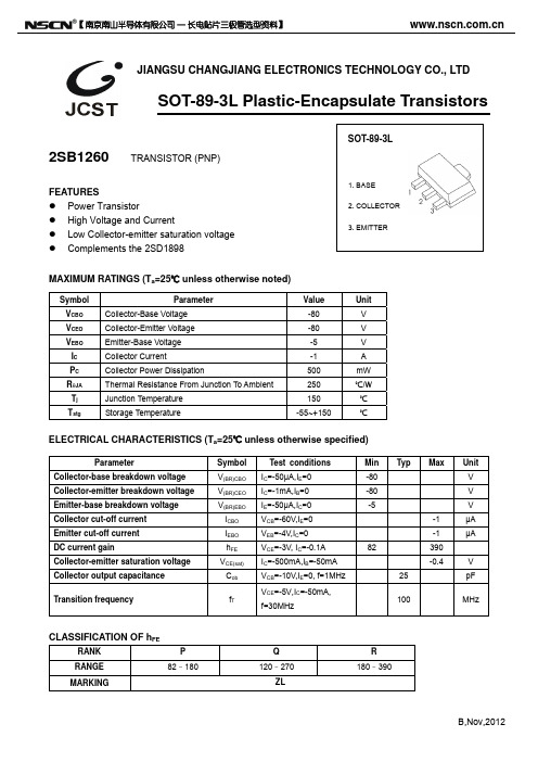
2SB1260贴片三极管 SOT-89封装三极管2SC2873参数
-800
Ta=25℃
-600
COLLECTOR-EMITTER SATURATION VOLTAGE VCEsat (mV)
BASE-EMITTER SATURATION VOLTAGE VBEsat (mV)
Ta=100 ℃
-100
-400
Ta=100 ℃
Ta=25℃
-200
-0 -0.1
-1
-10
COLLECTOR CURRENT
IC
(mA)
1000
Cob/Cib
——
VCB/VEB
f=1MHz IE=0/IC=0 Ta=25 ℃
600
PC
——
Ta
(pF)
100
Cib
COLLECTOR POWER DISSIPATION PC (mW)
500
400
CAPACITANCE
C
300
Cob
10
200
Dimensions In Millimeters Min. Max. 1.400 1.600 0.320 0.520 0.400 0.580 0.350 0.440 4.400 4.600 1.550 REF. 2.300 2.600 3.940 4.250 1.500 TYP. 3.000 TYP. 0.900 1.200
Symbol VCBO VCEO VEBO IC PC RθJA Tj Tstg Parameter Collector-Base Voltage Collector-Emitter Voltage Emitter-Base Voltage Collector Current Collector Power Dissipation Thermal Resistance From Junction To Ambient Junction Temperature Storage Temperature Value -80 -80 -5 -1 500 250 2mA IB=-0.1mA
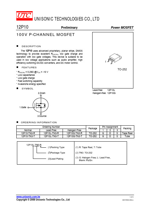
12P10L-TN3-R中文资料
Body Diode
Forward Voltage Drop
Fig. 1B Peak Diode Recovery dv/dt Waveforms
UNISONIC TECHNOLOGIES CO., LTD
PARAMETER Junction-to-Ambient Junction-to-Case
SYMBOL θJA θJC
MIN
TYP
ELECTRICAL CHARACTERISTICS (Tc=25°C, unless otherwise specified)
MAX 110 2.5
UNIT ℃/W ℃/W
2. Pulse width limited by TJ(MAX)
3. L=6.3mH, IAS=-9.4A, VDD=-25V, RG=25Ω, Starting TJ=25°C
4. ISD≤-11.5A, di/dt≤300μA/ s, VDD≤BVDSS, Starting TJ=25°C
THERMAL DATA
TJ
+150
℃
TSTG
-55 ~ +150
℃
Note: 1. Absolute maximum ratings are those values beyond which the device could be permanently damaged.
Absolute maximum ratings are stress ratings only and functional device operation is not implied.
Fig. 3A Gate Charge Test Circuit
PVII-12中文手册(版本号070502)
P/VⅡ-12交流金属封闭开关设备使用手册安全第一:在开关设备安装使用前请先仔细阅读本使用手册:●开关设备的使用场所应符合电气设备规定的使用条件的要求。
●安装、操作和维护均需由专职电气人员完成,该人员必须接受相应的培训。
●必须保证电气设备的联锁条件和工作规程的适用和安全性。
●有关开关设备的一切操作,都要遵守手册中的相关规定。
●不要超出开关设备正常工作条件下的技术参数中规定的数值。
●手册应放于安装、操作和维护人员方便拿到的地方。
用户的专职人员应对所有影响工作安全的事项负责,并正确管理开关设备。
如果对本操作手册尚有疑问,欢迎向我们提出,我们将提供进一步的咨讯与服务版权所有,本公司保留对此手册的修改权利。
严禁误用及滥用,包括盗版、篡改及断章取义并提供给第三方。
对所有其它渠道获取的咨讯,本公司概不负责。
目录产品概述概述符合标准技术参数外型尺寸和重量正常使用条件产品结构结构特点外壳与隔板手车功能隔室手车室母线室电缆室低压室防误闭锁装置压力释放装置储运与安装运输交货与保管安装安装现场的一般要求基础混凝土地坪上的基础框架柜体安装母线安装电缆连接电力电缆连接控制电缆连接开关装置接地其它事项运行与维护设备运行准备工作起动调试操作断路器手车断路器接地开关负荷开关组合式过电流继电器调试注意事项检查和维护概述检查和维护时间间隔检查维护主要附件VB2真空断路器手车典型接线图1 1 1 1 1 1 2 2 2 2 3 3 3 4 4 4 4 5 5 5 5 5 6 6 7 7 7 7 7 7 7 8 8 8 8 8 8 9 9 10 10 10 10 10 11 11 11 12概 述P/VⅡ-12型铠装移开式户内交流金属封闭开关设备是上海通用电气广电有限公司最新一代的户内成套配电装置。
设备适用于标称系统电压3~10kV,额定电流4000A及以下,额定频率50Hz的单母线或单母线分段三相交流户内配电系统,用于接收和分配电能,并对电路实行控制、保护及监测。
常用肖特基二极管参数
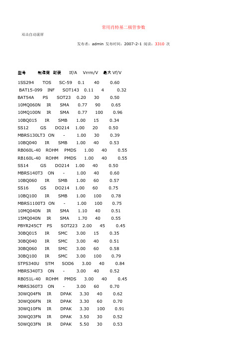
常用肖特基二极管参数双击自动滚屏发布者:admin 发布时间:2007-2-1 阅读:3310次型号制造商封装If/A Vrrm/V 最大Vf/V1SS294 TOS SC-59 0.1 40 0.60BAT15-099 INF SOT143 0.11 4 0.32BAT54A PS SOT23 0.20 30 0.5010MQ060N IR SMA 0.77 90 0.6510MQ100N IR SMA 0.77 100 0.9610BQ015 IR SMB 1.00 15 0.34SS12 GS DO214 1.00 20 0.50MBRS130LT3 ON - 1.00 30 0.3910BQ040 IR SMB 1.00 40 0.53RB060L-40 ROHM PMDS 1.00 40 0.55RB160L-40 ROHM PMDS 1.00 40 0.55SS14 GS DO214 1.00 40 0.50MBRS140T3 ON - 1.00 40 0.6010BQ060 IR SMB 1.00 60 0.57SS16 GS DO214 1.00 60 0.7510BQ100 IR SMB 1.00 100 0.78MBRS1100T3 ON - 1.00 100 0.7510MQ040N IR SMA 1.10 40 0.5115MQ040N IR SMA 1.70 40 0.55PBYR245CT PS SOT223 2.00 45 0.4530BQ015 IR SMC 3.00 15 0.3530BQ040 IR SMC 3.00 40 0.5130BQ060 IR SMC 3.00 60 0.5830BQ100 IR SMC 3.00 100 0.79STPS340U STM SOD6 3.00 40 0.84MBRS340T3 ON - 3.00 40 0.52RB051L-40 ROHM PMDS 3.00 40 0.45MBRS360T3 ON - 3.00 60 0.7030WQ04FN IR DPAK 3.30 40 0.6230WQ06FN IR DPAK 3.30 60 0.7030WQ10FN IR DPAK 3.30 100 0.9130WQ03FN IR DPAK 3.50 30 0.5250WQ03FN IR DPAK 5.50 30 0.5350WQ06FN IR DPAK 5.50 60 0.57 6CWQ06FN IR DPAK 6.60 60 0.58 6CWQ10FN IR DPAK pr 6.60 100 0.81 1N5817 ON 轴向 1.00 20 0.75 1N5818 ON 轴向 1.00 30 0.55 SB130 GS 轴向 1.00 30 0.501N5819 ON 轴向 1.00 40 0.60 MBR150 ON 轴向 1.00 50 1.00 MBR160 ON 轴向 1.00 60 1.0011DQ10 IR 轴向 1.10 100 0.8511DQ04 IR 轴向 1.10 40 0.5511DQ05 IR 轴向 1.10 50 0.5811DQ06 IR 轴向 1.10 60 0.58MBRS340TR IR SMC 3.00 40 0.431N5820 ON 轴向 3.00 20 0.851N5821 ON 轴向 3.00 30 0.381N5822 ON 轴向 3.00 40 0.52 MBR360 ON 轴向 3.00 60 1.00SS32 GS DO214 3.00 20 3.00 SS34 GS DO214 3.00 40 0.50 31DQ10 IR DO201 3.30 100 0.85 SB530 GS 轴向 5.00 30 0.57SB540 GS DO201 5.00 40 0.57 50SQ080 IR 轴向 5.00 80 0.6650SQ100 IR 轴向 5.00 100 0.66 MBR735 GS TO220 7.50 35 0.84 MBR745 GS TO220 7.50 45 0.84 MBR745 IR TO220 7.50 45 0.84 80SQ040 IR 轴向8.00 40 0.53 STQ080 IR TO220 8.00 80 0.728TQ100 TO220 8.00 100 0.7280SQ040 IR 轴向8.00 40 0.5380SQ035 IR DO204AR 8.00 35 0.53 HFA16PA60C IR TO247CT 8.00 600 1.7095SQ015 轴向9.00 15 0.3190SQ040 轴向9.00 40 0.4810TQ045 TO220 10.00 45 0.57MBR1035 GS TO220 10.00 35 0.84 MBR1045 ON TO220 10.00 45 0.84 STPS1045F ON ISO220 10.00 45 0.64 MBR2060CT ON TO220 10.00 60 0.85 MBR1060 ON TO220 10.00 60 0.95 PBYR10100 PS TO220 10.00 100 0.7010TQ040 IR TO220 10.00 40 0.57 MBR1045 IR TO220 10.00 45 0.8410CTQ150-1 IR D2pak 10.00 150 0.7340L15CTS IR D2pak 10.00 150 0.4185CNQ015A IR D61 80.00 15 0.32150K40A IR D08 150.00 400 1.3312CTQ040 IR TO220 12.00 45 0.73 MBR1545CT IR TO220 pr 15.00 45 0.72 MBR1660 GS TO220 16.00 60 0.7516CTQ080 IR TO220 pr 16.00 80 0.7216CTQ100 IR TO220 pr 16.00 100 0.7216CTQ100-1 IR D2Pak 16.00 100 0.7218TQ045 ON TO220 18.00 45 0.60 HFA16PB120 IR TO247 16.00 1200 3.00 MBR1645 IR TO220AC 16.00 45 0.6319CTQ015 IR TO220 19.00 15 0.3620CTQ045 IR TO220 pr 20.00 45 0.6420TQ045 IR TO220 20.00 45 0.57 MBR2045CT IR TO220 pr 20.00 45 0.84 MBR2090CT IR TO220 pr 20.00 90 0.80 MBR20100CT IR TO220 pr 20.00 100 0.80 MBR20100CT-1IR TO262 20.00 100 0.80 MBR2080CT IR TO220AB 20.00 80 0.85 MBR2545CT IR TO220AB 30.00 45 0.82 MBR3045WT IR TO247 30.00 4532CTQ030 IR TO220 pr 30.00 30 0.4932CTQ303-1 IR D2Pak 30.00 30 0.4930CPQ060 IR TO220 pr 30.00 60 0.62 30CPQ080 IR TO247AC 30.00 80 0.86 30CPQ100 IR TO247 pr 30.00 100 0.86 30CPQ150 IR TO247 pr 30.00 150 1.00 40CPQ040 IR TO247 pr 40.00 40 0.49 40CPQ045 IR TO247 pr 40.00 45 0.49 40CPQ050 IR TO247AA 40.00 50 0.53 40CPQ100 IR TO247 pr 40.00 100 0.77 40L15CT IR TO220AB 40.00 15 0.5347CTQ020 IR TO220 40.00 20 0.3448CTQ060 IR TO220 40.00 60 0.5840L15CW IR TO247 40.00 15 0.5242CTQ030 IR TO220 40.00 30 0.3840CTQ045 IR TO220 40.00 45 0.6840L45CW IR TO247 40.00 45 0.7040CPQ060 ON TO247 40.00 60 0.68 MBR4045WT IR TO247 40.00 45 0.59 MBR4060WT IR TO247 40.00 60 0.77 43CTQ100 IR TO220 40.00 100 0.98 52CPQ030 IR TO247 50.00 30 0.38 MBR6045WT IR TO247pr 60.00 45 0.73 STPS6045CPI ON TOP3I 60.00 45 0.84 65PQ015 IR TO247 65.00 15 0.5072CPQ030 IR TO247AC 70.00 30 0.51 85CNQ015 IR D61 80.00 15 0.3283CNQ100 IR D61 80.00 100 0.6780CPQ020 IR TO247 80.00 20 0.3282CNQ030A IR D61 80.00 30 0.3782CNQ045A IR D61 80.00 45 0.4783CNQ100A IR D61 80.00 100 0.67 120NQ045 IR HALFPAK 120.00 45 0.52 125NQ015 IR D67 120.00 15 0.33 122NQ030 IR D67 120.00 30 0.41 STPS16045TV ON ISOTOP 160.00 45 0.95 182NQ030 IR D67 180.00 30 0.41 200CNQ040 IR TO244AB 200.00 40 0.54 200CNQ045 IR TO244AB 200.00 45 0.54 200CNQ030 IR TO244AB 200.00 30 0.48 STPS24045TV ON ISOTOP 240.00 45 0.91 203CMQ080 IR TO244 200.00 80 1.03 240NQ045 IR HALFPAK 240.00 45 0.55301CNQ045 IR TO244 300.00 45 0.59 403CNQ100 IR TO244AB 400.00 100 0.83 440CNQ030 IR TO244AB 440.00 30 0.41。
2SB1260--三极管
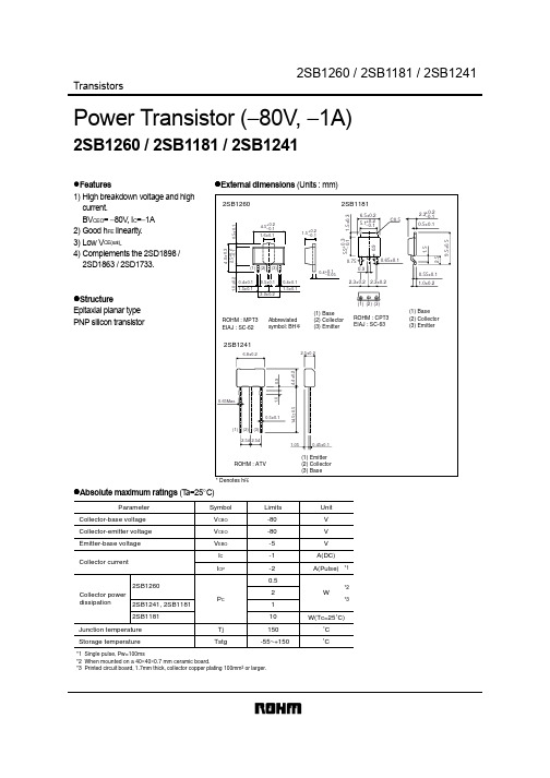
TransistorsPower Transistor (−80V, −1A)2SB1260 / 2SB1181 / 2SB1241!Features1) High breakdown voltage and high current.BV CEO = −80V , I C =−1A 2) Good h FE linearity .3) Low V CE(sat).4) Complements the 2SD1898 /2SD1863 / 2SD1733.!StructureEpitaxial planar type PNP silicon transistor!External dimensions (Units : mm)FE!Absolute maximum ratings (T a=25°C)Collector-base voltage Collector-emitter voltage Emitter-base voltage Collector currentCollector power dissipation Junction temperature Storage temperature*1 Single pulse, Pw=100ms*2 When mounted on a 40×40×0.7 mm ceramic board.*3 Printed circuit board, 1.7mm thick, collector copper plating 100mm 2 or larger.ParameterV CBO V CEO V EBO I C P CTj Tstg -80V V V A(DC)W˚C ˚C-80-5-1I CPA(Pulse)-2*10.52*21*3102SB12602SB1241, 2SB11812SB1181150-55~+150Symbol Limits Unit W(Tc=25˚C)Transistors!Electrical characteristics (T a=25°C)!Packaging specifications and h FEh FE values are classified as follows :Item P Q R h FE82~180120~270180~390!Electrical characteristic curvesFig.1 Grounded emitter propagationcharacteristicsBASE TO EMITTER VOLTAGE : VBE (V)C O L L E C T O R C U R R E N T : I C (m A )Fig.2 Grounded emitter outputcharacteristicsC O L L E C T O R C U R R E N T : I C (m A )COLLECTOR TO EMITTER VOLTAGE : V CE (V)Fig.3 DC current gain vs.collector currentCOLLECTOR CURRENT : I C (mA)D C C U R RE N T G A I N : hF ETransistorsFig.4 Collector-emitter saturationvoltage vs. collector currentC O L L E C T O R S A T U R A T I O N V O L T A G E : V C E (sa t ) (V )COLLECTOR CURRENT : I C (mA) Fig.5 Gain bandwidth product vs.emitter current EMITTER CURRENT : I E (mA)T R A N S I T I O N F R E Q U E N C Y : f T (M H z )Fig.6 Collector output capacitancevs. collector-base voltageC O L L E C T O R O U T P U T C A P A C I T A N C E : C o b (p F )COLLECTOR TO BASE VOLTAGE : V CB (V)Fig. 7 Emitter input capacitancevs. emitter-base voltageE M I T T E R I N P U T C A P A C I T A N C E : C i b (pF )EMITTER TO BASE VOLTAGE : V EB (V)Fig. 8 Safe operating area(2SB1260)C O L L E C T O R C U R R E N T : I C (A )COLLECTOR TO EMITTER VOLTAGE : V CE (V)Fig.9 Safe operating area (2SB1241)C O L L E C T O R C U R R E N T : I C (A )COLLECTOR TO EMITTER VOLTAGE : V CE (V)C O L L E C T O R C U R R E N T : I C (A )COLLECTOR TO EMITTER VOLTAGE : V CE (V)Fig.10 Safe operating area(2SB1181)。
2SB1260-X-TN3-T中文资料
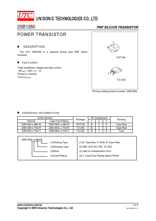
UNISONIC TECHNOLOGIES CO., LTD2SB1260PNP SILICON TRANSISTORPOWER TRANSISTORDESCRIPTIONThe UTC 2SB1260 is a epitaxial planar type PNP silicon transistor.FEATURES*High breakdown voltage and high current. BV CEO = -80V, I C = -1A *Good h FE linearity. *Low V CE(SAT)*Pb-free plating product number: 2SB1260LORDERING INFORMATIONOrder Number Pin AssignmentNormal Lead Free Plating Package 1 2 3Packing2SB1260-x-AB3-R 2SB1260L-x-AB3-R SOT-89 B C E Tape Reel 2SB1260-x-TN3-R 2SB1260L-x-TN3-R TO-252 B C E Tape Reel 2SB1260-x-TN3-T 2SB1260L-x-TN3-T TO-252 B C E TubeABSOLUATE MAXIUM RATINGS (Ta = 25 )PARAMETER SYMBOL RATINGS UNITCollector -Base Voltage V CBO -80 V Collector -Emitter Voltage V CEO -80 V Emitter -Base Voltage V EBO -5 V Peak Collector Current (single pulse, Pw=100ms) I CM -2 A DC Collector Current I C -1 A SOT-89 0.5 WPower DissipationTO-252 P D1.9 WOperating Temperature T J +150Storage TemperatureT STG -40 ~ +150Note 1. Printed circuit board,1.7mm thick, collector copper plating 100mm 2 or larger.2. Absolute maximum ratings are those values beyond which the device could be permanently damaged. Absolute maximum ratings are stress ratings only and functional device operation is not implied.ELECTRICAL CHARACTERISTICS (Ta= 25 , unless otherwise specified)PARAMETER SYMBOLTEST CONDITIONS MIN TYP MAX UNIT Collector Base Breakdown Voltage BV CBO I C = -50 A -80 V Collector Emitter Breakdown Voltage BV CEO I C = -1mA -80 VEmitter Base Breakdown Voltage BV EBO I E = -50 A-5 VCollector Cut-Off Current I CBO V CB =-60V -1 A Emitter Cut-Off Current I EBO V EB =-4V -1A DC Current Gain(Note 1) h FE V CE =-3V, I OUT =-0.1A 82 390Collector-Emitter Saturation Voltage V CE(SAT)I C =-500mA, I B =-50mA -0.4 V Transition Frequency f T V CE = -5V, I E =50mA, f=30MHz 100 MHz Output Capacitance Cob V CB =-10V, I E =0, f=1MHz 25 pFNote 1: Pulse test: P W <300µs, Duty Cycle<2%CLASSIFICATION OF h FERANK P Q RRANGE 82 ~ 180 120 ~ 270 180 ~ 390■TYPICAL CHARACTERICSBase to Emitter Voltage, V BE (V)Grounded Emitter PropagationCharacteristicsC o l l e c t o rC u r r e n t , I c (mA )Collector Current, Ic(mA)DC Current Gain vs . CollectorD C C u r r e n t G a i n , h F ECollector to Emitter Voltage, V CE (V)Grounded Emitter OutputCharacteristicsC o l l e c t o r C u r r e n t , Ic (m A )Emitter Current , I E (mA)Collector-emitter Saturation VoltageC o l l e c t o r S a t u r a t i o n V o l t a g e , V C E (S A T ) ( V )Collector to Base Voltage, V CB (V)Collector Output Capacitance vs.C o l l e c t o r O u t p u t C a p a c i t a n c e , C o b (p F )Collector Current , Ic(mA)T r a n s i t i o n F r e q u e n c y , f T (M H z )Gain Bandwidth Product vs. EmitterCurrentTYPICAL CHARACTERICS(Cont.)Collector to Emitter Voltage, V CE (V)Safe Operating AreaC o l l e c t o r C u r r e n t , I c (A)Emitter To Base Voltage, V EB (V)Emitter Input Capacitance vs. Emitter-Base VoltageE m i t t e r I n p u t C a p a c i t a n c e , C i b (pF )。
电磁保护设备TeSys GV系列产品参数表说明书
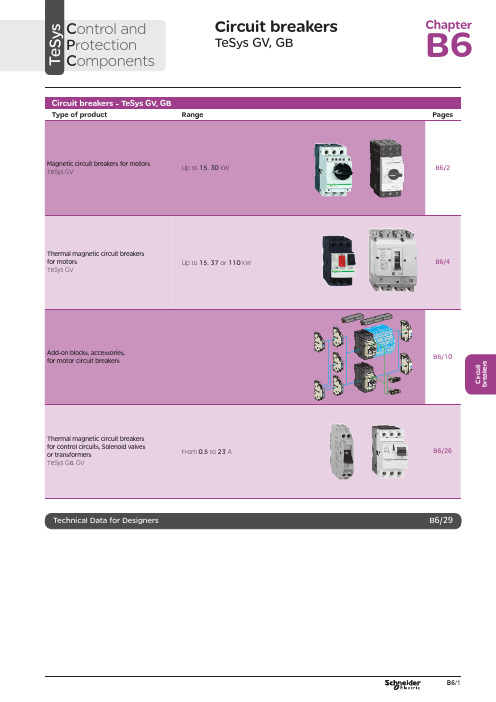
C i r c u i t b r e a k e r sCircuit breakersTeSys GV, GBC ontrol and P rotection C omponentsChapterB60.75g g 1.1g g 1.5375 2.533.5 LR2 K0308GV2LE071.1g g –––––– 2.533.5 LR2 K0308GV2LE071.5g g 1.5g g 3375451 LR2 K0310GV2LE08––– 2.2g g –––451 LR2 K0312GV2LE082.2g g 3501004375 6.378 LR2 K0312GV2LE103g g 410100 5.537510138 LR2 K0314GV2LE144g g 5.510100–––10138 LR2 K0316GV2LE14––––––7.537510138 LRD 14GV2LE14––––––937514170 LRD 16GV2LE165.515507.56751137514170 LR2 K0321GV2LE167.5155096751537518223 LRD 21GV2LE20915401147518.537525327 LRD 22GV2LE2211154015475–––25327 LRD 22GV2LE2215105018.54752237532416LRD 32GV2LE32(1) As % of Icu.g ) > 100 kA.GV2 LE10D F 526144.t i fC i r c u i t b r e a k e r s0.09––––––0.45LRD 03GV2L030.12g g –––0.37g g 0.638LRD 04GV2L040.18g g ––––––0.638LRD 04GV2L04––––––0.55g g 113LRD 05GV2L050.25g g ––––––113LRD 05GV2L05––––––0.75g g 113LRD 06GV2L050.37g g 0.37g g –––113LRD 05GV2L050.55g g 0.55g g 1.1g g 1.622.5LRD 06GV2L06–––0.75g g ––– 1.622.5LRD 06GV2L060.75g g 1.1g g 1.54100 2.533.5LRD 07GV2L07Example: GV3 L32 becomes GV3 L326.(1) As % of Icu. Associated current limiter or fuses, where required. See characteristics page B6/33.g > 100 kA.GV2 L10D F 526145.t i fGV3 L65D F 526146.t i fTeSys GVThermal-magnetic motor circuit breakers GV2 ME0.06gg––––––0.16…0.252.4GV2ME020.09g g––––––0.25…0.405GV2ME030.12 0.18g g g g – –– –– – 0.37 –g–g –0.40…0.638GV2ME040.25gg––– 0.55gg0.63…113GV2ME050.37 0.55 –g g –g g –0.37 0.55 0.75g g g g g g – 0.75 1.1– g g – g g 1…1622.5GV2ME060.75g g1.1gg1.5375 1.6...2.533.5GV2ME071.1 1.5g g g g 1.5 2.2g g g g 2.2 3 3 375 75 2.5 (4)51GV2ME082.2gg350100 43754...6.378GV2ME103 4g g g g 4 5.510 10100 100 5.5 7.5 3 375 756 (10)138GV2ME145.5 –15 –50 –7.5 – 6 –75 – 9 11 3 375 759…14170GV2ME167.5155096751537513…18223GV2ME209154011475 18.537517…23327GV2ME2111154015475 –––20…25327GV2ME22 (3)15105018.54752237524 (32)416GV2ME32Motor circuit breakers from 0.06 to 15 kW / 400 V, with lugsTo order thermal magnetic circuit breakers with connection by lugs, add the digit 6 to the end of reference selected above.Example: GV2 ME08 becomes GV2 ME086.Thermal magnetic circuit breakers GV2 ME with built-in auxiliary contact block With instantaneous auxiliary contact block (composition, see page B6/11):b GV AE1, add suffix AE1TQ to the motor circuit breaker reference selected above. Example: GV2 ME01AE1TQ .b GV AE11, add suffix AE11TQ to the motor circuit breaker reference selected above. Example: GV2 ME01AE11TQ .b GV AN11, add suffix AN11TQ to the motor circuit breaker reference selected above. Example: GV2 ME01AN11TQ .These circuit breakers with built-in contact block are sold in lots of 20 units in a single pack.(1) As % of Icu.(2) The thermal trip setting must be within the range marked on the graduated knob.(3) Maximum rating which can be mounted in enclosures GV2 MC or MP , please consult your Regional Sales Office. g > 100 kA.GV2 ME10D F 526134.t i fC i r c u i t b r e a k e r sTeSys GVTeSys protection componentsThermal-magnetic motor circuit breakers GV2 MEReferences0.06g g ––– 0.16…0.25 2.4GV2ME0230.09g g ––– 0.25…0.405GV2ME0330.120.18g g g g –––0.40…0.638GV2ME0430.250.37g g g g 0.37g g 0.63…113GV2ME0530.370.55g g g g 0.370.550.75g g g g g g 1…1.622.5GV2ME0630.75g g1.1g g 1.6…2.533.5GV2ME0731.11.5g g g g 1.52.2g g g g 2.5…451GV2ME0832.2g g 350100 4…6.378GV2ME10334g g g g 45.510101001006…10138GV2ME1435.515507.5675 9…14170GV2ME1637.515509675 13…18223GV2ME203911151540401147517…23327GV2ME2131115401547520 (25)327GV2ME223Contact blocksDescription Mounting Maximum number Type of contacts Sold in lots of Unitreference Instantaneous auxiliary contactsFront 1N/O + N/C 10GVAE113N/O + N/O 10GVAE203LH side2N/O + N/C 1GVAN113N/O + N/O1GVAN203AccessoryDescriptionApplicationSold in lots of Unitreference Cable end reducerFor connection of conductors from 1 to 1.5 mm 220LA9D99(1) For connection of conductors from 1 to 1.5 mm 2, the use of an LA9 D99 cable end reducer is recommended.(2) Maximum rating which can be mounted in enclosures GV2 MC or MP , please consult your Regional Sales Office (3) The thermal trip setting must be within the range marked on the graduated knob.g > 100 kA.GV2 ME pp 3D F 526135.t i fLA9 D99D F 533898.e p sTeSys GVReferencesTeSys protection componentsThermal-magnetic motor circuit breakersGV2 P, GV3 P and GV3 ME80GV2 P10D F 526137.t i fGV3 P65D F 526139.t i fGV3 P651D F 526140.t i fC i r c u i t b r e a k e r sTeSys GVReferences93610011181001581007.59707010010091150501001001115101010010012…20GV7RS20 2.0109113636100100111518181001001518.58810010015…25GV7RE25 2.0109117070100100111550501001001518.5101010010015…25GV7RS25 2.01018.53610018.522181810010022810025…40GV7RE40 2.01018.57010018.550100221010025…40GV7RS40 2.0102236100301810030810030…50GV7RE50 2.01522701003050100301010030 (50)GV7RS502.01537361004555181810010055810048...80GV7RE80 2.040377010045555050100100551010048...80GV7RS80 2.0404536100–1810075810060...100GV7RE100 2.0404570100–50100751010060...100GV7RS100 2.0405575353510010075903030100100901108810010090 (150)GV7RE1502.020557570701001007590505010010090110101010010090…150GV7RS150 2.02090110353510010011013216030303010010010016020088100100132…220GV7RE220 2.3509011070701001001101321605050501001001001602001010100100132…220GV7RS220 2.350(1) As % of lcu.TeSys protection componentsThermal-magnetic motor circuit breakers GV7 RGV7 RE40D F 526138.t i fGV7 RS220D F 526141.t i f0.12–0.120.180.18–0.370.40…0.6313GV2RT040.090.120.250.370.250.370.370.550.63…122GV2RT050.180.250.370.550.370.550.370.550.750.751.11…1.633GV2RT060.370.750.751.1 1.11.51.6…2.551GV2RT070.550.75 1.11.5 1.51.52.2 2.23 2.5…478GV2RT081.12.22.23344…6.3138GV2RT101.52.234445.5 5.57.56…10200GV2RT142.23 5.55.57.57.59119…14280GV2RT1647.57.5991513…18400GV2RT205.5911111118.517…23400GV2RT21(1) The thermal trip setting must be within the range marked on the graduated knob.GV2 RTD F 526142.t i fC i r c u i t b r e a k e r sblack handle, blue legend plate(1) The thermal trip setting must be within the range marked on the graduated knob.(2) Other accessories such as mounting, cabling and marking accessories are identical to those used for GV2 ME motor circuit breakers, see page B6/13.GV2 RTD F 526142.t i fD F 526340.e p sC i r c u i t b r e a k e r sTeSys GVDescription Mounting Maximum number Type of contacts Sold inlots of Unitreference Instantaneous auxiliary contactsFront (1)1N/O or N/C (2)10GVAE1N/O + N/C 10GVAE11N/O + N/O10GVAE20Side (LH)2N/O + N/C1GVAN11N/O + N/O1GVAN20Fault signalling contact + instantaneous auxiliary contact Side (3) (LH)1N/O (fault)+ N/O1GVAD1010+ N/C1GVAD1001N/C (fault)+ N/O1GVAD0110+ N/C1GVAD0101Short-circuit signalling contactSide (LH)1C/O common point1GVAM11(1 block on RH sideof circuit breaker GV2 ME)50 Hz GVAX11560 Hz GVAX116127 V60 Hz GVAX115220…240 V 50 Hz GVAX22560 Hz GVAX226380…400 V50 Hz GVAX38560 Hz GVAX386415…440 V 50 Hz GVAX415440 V60 Hz GVAX385Add-on contact blocksDescriptionMountingMaximum number Reference Visible isolation block (5)Front (1)1GV2AK00 (6)LimitersAt top(GV2 ME and GV2 P)1GV1L3Independent1LA9LB920(1) Mounting of a GV AE contact block or a GV2 AK00 visible isolation block on GV2 P and GV2 L .(2) Choice of N/C or N/O contact operation, depending on which way round the reversible block is mounted.(3) The GV AD is always mounted next to the circuit breaker.(4) To order an undervoltage trip: replace the dot (p ) in the reference with a U , example: GV AU025. To order a shunt trip: replace the dot (p ) in the reference with an S , example: GV AS025.(5) Visible isolation of the 3 poles upstream of circuit breaker GV2 P and GV2 L .Visible isolation block GV2 AK00 cannot be used with motor circuit breakers GV2 P32 and GV2 L32 (Ith max = 25 A).(6) Ie Max = 32 A.ReferencesTeSys protection componentsThermal-magnetic and magnetic motor circuit breakers GV2 with screw clamp connectionsAdd-on blocks and accessoriesCharacteristics:pages B6/89 and B6/94Dimensions, schemes:pages B6/70 to B6/82LA9LB920D B 126629.e p sC i r c u i t b r e a k e r sTeSys GVTerminal blockfor supply to one or more GV2 G busbar setsConnection from the top1GV1G09Can be fitted with current limiter GV1 L3 (GV2 ME and GV2 P)1GV2G05Cover for terminal block For mounting in modular panels10LA9E07Flexible 3-pole connection for connecting a GV2 to a contactor LC1-D09…D25 Centre distance between mounting rails: 100…120 mm10GV1G02Set of connections upstream/downstream For connecting GV2 ME to a printed circuit board 10GV2GA01“Large Spacing” adapter UL 508 type EFor GV2 P pp H7 (except 32 A)1GV2GH7Clip-in marker holders (supplied with each circuit breaker)For GV2 P , GV2 L, GV2 LE and GV2 RT (8 x 22 mm)100LA9D92ReferencesTeSys protection componentsThermal-magnetic and magnetic motor circuit breakers GV2 with screw clamp connectionsAccessoriesDimensions, schemes:pages B6/70 to B6/82D B 417942.e p sTeSys GVD B 126631.e p sD B 126630.e p sD B 126632.e p s7P B 106297_45.e p sExtended Rotary HandleAllows a circuit breaker or a starter-controller installed in back of an enclosure to be operated from the front of the enclosure.A rotary handle can be black or red/yellow, IP54 or IP65. It includes a function for locking the circuit breaker or the starter in the O (Off) or I (On) position(depending of the type of rotary handle) by means of up to 3 padlocks with a shank diameter of 4 to 8 mm. The extended shaft must be adjusted to use in different size enclosures. The IP54 rotary handle is fixed with a nut (Ø22) to make easierthe assembling. The new Laser Square tool brings the accuracy to align the circuit breaker and the rotary handle.device(padlocks not included)ReferencesTeSys protection componentsThermal-magnetic and magnetic motor circuit breakers GV2 with screw clamp connectionsC i r c u i t b r e a k e r sTeSys GVDescriptionMounting Maximum number Type of contacts Sold inlots of Unitreference Instantaneous auxiliary contactsFront1N/O or N/C (1)10GVAE1N/O + N/C 10GVAE11 (2)N/O + N/O10GVAE20 (2)Side (LH)2N/O + N/C1GVAN11 (2)N/O + N/O1GVAN20 (2)Fault signalling contact + instantaneous auxiliary contactFront 1N/O (fault)+ N/O1GVAED101 (2)N/O (fault)+ N/C1GVAED011 (2)Side (3) (LH)1N/O (fault)+ N/O1GVAD1010+ N/C1GVAD1001N/C (fault)+ N/O1GVAD0110+ N/C1GVAD0101Short-circuit signalling contact Side (LH)1C/O common point 1GVAM11(4)MountingVoltage ReferenceSide(1 block on RH side of circuit breaker)24 V 50 Hz GVA p 02560 Hz GVA p 02648 V 50 Hz GVA p 05560 Hz GVA p 05610050 Hz GVA p 107100…110 V 60 Hz GVA p 107110…115 V 50 Hz GVA p 11560 Hz GVA p 116120…127 V 50 Hz GVA p 125127 V 60 Hz GVA p 115200 V50 Hz GVA p 207200…220 V 60 Hz GVA p 207220…240 V 50 Hz GVA p 22560 Hz GVA p 226380…400 V 50 Hz GVA p 38560 Hz GVA p 386415…440 V 50 Hz GVA p 415415 V 60 Hz GVA p 416440 V 60 Hz GVA p 385480 V 60 Hz GVA p 415500 V 50 Hz GVA p 505600 V60 HzGVA p 505AccessoriesDescription Reference Sets of 3-pole 115 A busbars Pitch: 64 mm2 tap-off GV3 P pp and GV3 L pp GV3G2643 tap-off GV3 P pp and GV3 L pp GV3G364Cover “Large Spacing” UL 508 type E (Only one cover required on supply side)GV3 P ppGV3G66(1) Choice of N/C or N/O contact operation, depending on which way round the reversible block is mounted.(2) Contact blocks available in version with spring terminal connections. Add a figure 3 at the end of the references selected above. Example: GV AED101 becomes GV AED1013.(3) The GV AD pp is always mounted next to the circuit breaker.(4) To order an undervoltage trip: replace the dot (p ) in the reference with a U , example: GV AU025. To order a shunt trip: replace the dot (p ) in the reference with an S , example: GV AS025.Add-on blocks and accessoriesGV3 G66D F 537424.e p sTeSys GVD B 126637.e p sD B 126636.e p sD B 126632.e p s7P B 106297_45.e p sExtended Rotary HandleAllows a circuit breaker or a starter-controller installed in back of an enclosure to be operated from the front of the enclosure.A rotary handle can be black or red/yellow, IP54 or IP65. It includes a function for locking the circuit breaker or the starter in the O (Off) or I (On) position(depending of the type of rotary handle) by means of up to 3 padlocks with a shank diameter of 4 to 8 mm. The extended shaft must be adjusted to use in different size enclosures. The IP54 rotary handle is fixed with a nut (Ø22) to make easierthe assembling. The new Laser Square tool brings the accurency to align the circuit breaker and the rotary handle.For English 10-GVAPSEN For German 10-GVAPSDE For Spanish10-GVAPSES For Chinese 10-GVAPSCN For Portuguese 10-GVAPSPT For Russian 10-GVAPSRU For Italian10-GVAPSITD F 526342.e p sB6/21C i r c u i t b r e a k e r sTeSys GVfor locking the Start button (on open-mounted product)using up to 3 padlocks(padlocks to be ordered separately)External operator for mounting on enclosure door.Red Ø40 knob on yellow plate, padlockable in position O (with up to 3 padlocks). Door locked when knob in position I, and when knob padlocked in position O.GK3AP03(1) 1 voltage trip OR 1 fault signalling contact to be fitted inside the motor circuit breaker.Other versions24 to 690 V, 50 or 60 Hz voltage trips for circuit breakers GV3 ME80.Please consult your Regional Sales Office.ReferencesTeSys protection componentsMotor circuit breakers GV3 ME80 and GK3 EF80Add-on blocks and accessoriesCharacteristics:pages B6/89 and B6/92Dimensions:page B6/47B6/22D F 526344.e p sB6/23C i r c u i t b r e a k e r sTeSys GVThese allow remote indication of the circuit breaker contact states. They can be used for signalling, electrical locking, relaying, etc. They are available in two versions: standard and low level. They include a terminal block and the auxiliary circuits leave the circuit breaker through a hole provided for this purpose.They perform the following functions, depending on where they are located in the circuit breaker:Low levelGV7AB11Fault discrimination devicesThese make it possible to:b either differentiate a thermal fault from a magnetic fault,b or open the contactor only in the event of a thermal fault.VoltageReference a 24...48 and c 24…72 V GV7AD111 (1)z 110…240 VGV7AD112 (1)Electric tripsThese allow the circuit breaker to be tripped via an electrical control signal.b Undervoltage trip GV7 AUv Trips the circuit breaker when the control voltage drops below the tripping threshold, which is between 0.35 and 0.7 times the rated voltage.v Circuit breaker closing is only possible if the voltage exceeds 0.85 times the rated voltage. Circuit breaker tripping by a GV7 AU trip meets the requirements of IEC 60947-2.b Shunt trip GV7 ASTrips the circuit breaker when the control voltage rises above 0.7 times the rated voltage.b Operation (GV7 AU or GV7 AS)v When the circuit breaker has been tripped by a GV7 AU or AS, it must be reset either locally or by remote control. (For remote control, please consult your Regional Sales Office).v Tripping has priority over manual closing: if a tripping instruction is present, manual action does not result in closing, even temporarily, of the contacts.v Durability: 50 % of the mechanical durability of the circuit breaker.TypeVoltageReference Undervoltage trip48 V, 50/60 HzGV7AU055 (1)110…130 V, 50/60 Hz GV7AU107 (1)200…240 V, 50/60 Hz GV7AU207 (1)380…440 V, 50/60 Hz GV7AU387 (1)525 V, 50 HzGV7AU525 (1)Shunt trip48 V, 50/60 HzGV7AS055 (1)110…130 V, 50/60 Hz GV7AS107 (1)200…240 V, 50/60 Hz GV7AS207 (1)380…440 V, 50/60 Hz GV7AS387 (1)525 V, 50 HzGV7AS525 (1)(1) For mounting of a GV7 AD or a GV7 AU or AS.ReferencesTeSys protection componentsThermal-magnetic motor circuit breakers GV7 R with screw clamp connectionsAdd-on blocks and accessoriesCharacteristics:pages B6/51, B6/52 and B6/56Dimensions:pages B6/79 to B6/81Schemes:page B6/83B6/24B6/25C i r c u i t b r e a k e r sTeSys GVDescription ApplicationFor use on contactors Sold in lots of Unitreference Clip-on connectors for GV7 RUp to 150 A, 1.5…95 mm 2–3GV7AC021Up to 220 A, 1.5…185 mm 2–3GV7AC022Spreader 3-pole (1)To increase the pitch to 45 mm–1GV7AC03Terminal shields IP 405 (1)Supplied with sealing accessory–1GV7AC01Phase barriersSafety accessories used when fitting of shields is impossible –2GV7AC04Insulating screens Ensure insulation between the connections and the backplate –2GV7AC05Kits for combination with contactor (2)Allowing link between thecircuit breaker and the contactor. The cover provides protection against direct finger contactLC1 F115…F1851GV7AC06LC1 F225 and F2651GV7AC07LC1 D115 and D1501GV7AC08Replaces the circuit breaker front cover; secured by screws. It includes a device for locking the circuit breaker in the O (Off) position by means of up to 3 padlocks with a shank diameter of 5 to 8 mm (padlocks not included). A conversion accessory allows the direct rotary handle to be mounted on the enclosure door. In this case, the door cannot be opened if the circuit breaker is in the “ON” position. Circuit breaker closing is inhibited if the enclosure door is open.Description TypeDegree of protection Reference Direct rotary handleBlack handle, black legend plate IP 40GV7AP03Red handle, yellow legend plateIP 40GV7AP04Adapter plate (3)Four mounting direct rotary handle on enclosure doorIP 43GV7AP05Allows a circuit breaker installed in the back of an enclosure to be operated from the front of the enclosure. It comprises:b a unit which screws onto the front cover of the circuit breaker,b an assembly (handle and front plate) to be fitted on the enclosure door,b an extension shaft which must be adjusted (distance between the mounting surface and the door: 185 mm minimum, 600 mm maximum). It includes a device for locking the circuit breaker in the O (Off) position by means of up to 3 padlocks with a shank diameter of 5 to 8 mm (padlocks not included). This prevents the enclosure door from being opened.DescriptionTypeDegree of protection Reference Extended rotary handleBlack handle, black legend plate IP 55GV7AP01Red handle, yellow legend plateIP 55GV7AP02Allows circuit breakers not fitted with a rotary handle to be locked in the O (Off) position by means of up to 3 padlocks with a shank diameter of 5 to 8 mm (padlocks not included).Description ApplicationReference Locking deviceFor circuit breaker not fitted with a rotary handleGV7V01(1) Terminal shields cannot be used together with spreaders.(2) The kit comprises links, a protective shield and a depth adjustable metal bracket for the breaker.(3) This conversion accessory makes it impossible to open the door if the device is closed and prevents the device from being closed if the door is open.ReferencesTeSys protection componentsThermal-magnetic motor circuit breakers GV7 R with screw clamp connectionsAccessoriesGV7 AC07D F 537429.e p sGV7 AC08D F 537428.e p sDimensions:pages B6/79 to B6/81B6/260.5 6.63GB2DB051143GB2DB062263GB2DB073403GB2DB084503GB2DB095663GB2DB106833GB2DB1281083GB2DB14101383GB2DB16121653GB2DB20162203GB2DB21202703GB2DB22(1) Conforming to IEC 60947-1.GB2 CBppD F 526243.t i fGB2 CD ppD F 526244.t i fGB2 DBppD F 526245.t i fPresentation, selection :page B6/84Characteristics :pages B6/85 to B6/87Dimensions :page B6/88Schemes :page B6/88B6/27C i r c u i t b r e a k e r s(1) Conforming to IEC 60947-1.Accessories for circuit breakers GB2-CB, DB and CSDescriptionSold in lots of Unitreference Busbar set for supply to 10 GB2 DB or20 GB2 CB or GB2 CS with 2 connectors1GB2G210Supply connector 10GB2G01GB2 CS ppD F 526246.t i fPresentation, selection :page B6/84Characteristics :pages B6/85 to B6/87Dimensions :page B6/88Schemes :page B6/88B6/28B6/29B6/30TeSys GVCharacteristicsTeSys protection componentsMagnetic motor circuit breakers GV2 LE and GV2 LReferences:pages B6/2 and B6/3Dimensions:pages B6/43 to B6/47Schemes:page B6/48add-on contact blocks. Side by side mounting is possible up to 40 °C.(2) When mounting on a vertical rail, fit a stop to prevent any slippage.(1) As % of Icu.Average operating times at 20 °C related to multiples of the setting currentD F 534092.e p s1 3 poles from cold state2 2 poles from cold state3 3 poles from hot stateDynamic stressI peak = f (prospective Isc) at 1.05 Ue = 435 VD F 534093.e p s1 Maximum peak current2 32 A3 25 A4 18 A5 14 A6 10 A7 6.3 A8 4 A9 2.5 A 10 1.6 A11 Limit of rated ultimate breaking capacity on short-circuit of GV2 LE (14, 18, 23 and 25 A ratings).Dynamic stressI peak = f (prospective Isc) at 1.05 Ue = 435 VD F 534094.e p s1 Maximum peak current2 32 A3 25 A4 18 A5 14 A6 10 A7 6.3 A8 4 A9 2.5 A 10 1.6 A11 Limit of rated ultimate breaking capacity on short-circuit of GV2 LE (14, 18, 23 and 25 A ratings).Thermal limit in kA 2s in the magnetic operating zone Sum of I 2dt = f (prospective Isc) at 1.05 Ue = 435 V22Prospective Isc (kA)D F 534095.e p s1 32 A 2 25 A3 18 A4 14 A5 10 A6 6.3 A7 4 A8 2.5 A9 1.6 AThermal limit in kA 2s in the magnetic operating zone Sum of I 2dt = f (prospective Isc) at 1.05 Ue = 435 V22D F 534096.e p s1 25 A and 32 A 2 18 A3 14 A 4 10 A5 6.3 A6 4 A7 2.5 A8 1.6 AThermal limit in kA 2s in the magnetic operating zone Sum of I 2dt = f (prospective Isc) at 1.05 Ue = 435 V22D F 534097.e p s1 32 A (GV2 LE32)2 25 A and 32 A (GV2 L32)3 18 A4 14 A5 10 A6 6.3 A7 4 A8 2.5 A9 1.6 A10 Limit of rated ultimate breaking capacity on short-circuit of GV2 LE (14, 18, 23 and 25 A ratings).Average operating time at 20 °C without prior current flowx the setting current (Ir)D F 534098.e p s1 3 poles from cold state2 2 poles from cold state3 3 poles from hot stateA Thermal overload relay protection zoneB GV3 L protection zoneDynamic stressI peak = f (prospective Isc) at 1.05 Ue = 435 VProspective Isc (kA)D B 418280.e p s1 Maximum peak current2 GV3 L653 GV3 L504 GV3 L405 GV3 L326 GV3 L25Thermal limit in A 2sSum of I 2dt = f (prospective Isc) at 1.05 Ue = 435 V2Prospective Isc (kA)D B 418279.e p s1 GV3 L652 GV3 L503 GV3 L404 GV3 L325 GV3 L25TeSys GVDimensions, mountingD F 537440.e p sD F 537441.e p sD F 537444.e p sTeSys protection componentsMagnetic motor circuit breakers GV2 L and GV2 LETeSys GVDimensions, mounting TeSys protection componentsMagnetic motor circuit breakers GV2 L and GV2 LED B 127415.e p sD B 127414.e p sa b Mini Maxi Mini Maxi GV2 APN pp140250GV2 APN pp + GV APH02151250GV2 APN pp + GV APK11250434--GV2 APN pp + GV APH02 + GV APK11--250445TeSys GVDimensions,mounting Sets of busbars GV2 G445, GV2 G454, GV2 G472, with terminal block GV2 G05D F 537451.e p sGV2 G445224269314359GV2 G454260314368422GV2 G472332404476548D F 537452.e p sD F 537454.e p sGV2 G345 (3 x 45 mm)134GV2 G354 (3 x 54 mm)152TeSys protection componentsMagnetic motor circuit breakers GV2 L and GV2 LED F 537480.e psD F 537435.e p sD F 510637.e p sD F 510638.e p sD B 127416.e p sD B 127417.e p sa b Mini Maxi Mini Maxi GV3 APN pp189300--GV3 APN pp + GV APK12300481GV3 APN pp + GV APH03--200300GV3 APN pp + GV APH03 + GV APK12--300492TeSys GVSchemesTeSys protection componentsMagnetic motor circuit breakers GV2 L, GV2 LE, GV3 LD F 537474.e p sD F 537475.e p sD F 537476.e p sGV2 ME, GV2 P , GV3 ME, GV3 P and GV7 R motor circuit breakers are 3-pole thermal-magnetic circuit breakers specifically designed for the control and protection of motors , conforming to standards IEC 60947-2 and IEC 60947-4-1.Connection GV2GV2 ME and GV2 P circuit breakers are designed for connection by screw clamp terminals.Circuit breaker GV2 ME can be supplied with lugs or spring terminal connections.Spring terminal connections ensure secure, permanent and durable clamping that is resistant to harsh environments, vibration and impact and are even more effective when conductors without cable ends are used. Each connection can take two independent conductors.GV3GV3 circuit breakers feature connection by BTR screws (hexagon socket head), tightened using a n° 4 Allen key.This type of connection uses the Ever Link ® system with creep compensation (1) (Schneider Electric patent).This technique makes it possible to achieve accurate and durable tightening torque, in order to avoid cable creep.GV3 circuit breakers are also available with connection by lugs. This type of connection meets the requirements of certain Asian markets and is suitable for applications subject to strong vibration, such as railway transport.GV7GV7 circuit breakers: with connection by screw clamp terminals (for bars and lugs) and by clip-on connectors.OperationControl is manual and local when the motor circuit breaker is used on its own.Control is automatic and remote when it is associated with a contactor.GV2 ME and GV3 ME80Pushbutton control.Energisation is controlled manually by operating the Start button “I” 1.De-energisation is controlled manually by operating the Stop button “O” 2, or automatically by the thermal-magnetic protection elements or by a voltage trip attachment.GV2 P , GV3 P and GV7 Rb Control by rotary knob: for GV2 P and GV3 P b Control by rocker lever: for GV7 R.Energisation is controlled manually by moving the knob or rocker lever to position “I” 1.De-energisation is controlled manually by moving the knob or rocker lever to position “O” 2.De-energisation due to a fault automatically places the knob or rocker lever in the “Trip” position 3.Re-energisation is possible only after having returned the knob or rocker lever to position “O”.(1) Creep: normal crushing phenomenon of copper conductors, that is accentuated over time.GV2 MEwith screw clamp terminals124D F 526134.t i fGV2 MEwith spring terminals connections124D F 526135.t i fGV3 P1324D F 526136.t ifGV2 P1342D F 526137.t i fGV7 R132D F 526138.t i f。
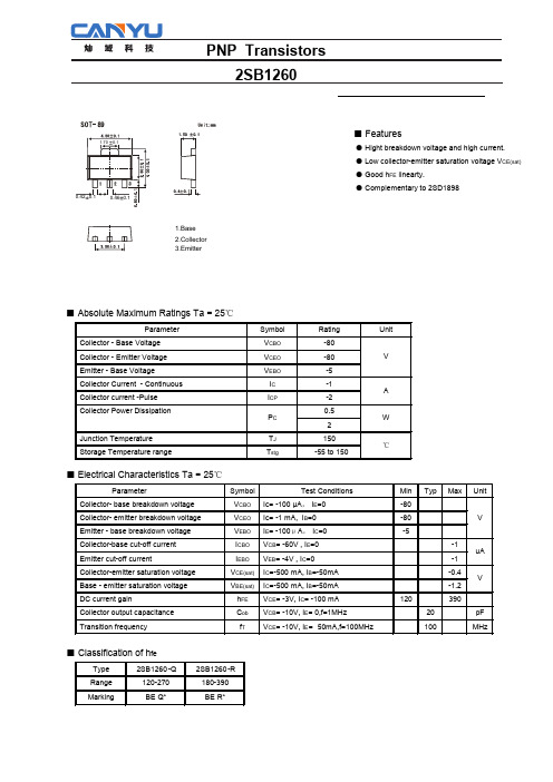
2SB1260 PDF规格书
Ta =25 °C −2 −1 −0.5
−0.2 −0.1 −0.05
IC /IB =20 10
−0.02 −0.01
−1 −2 −5 −10 −20 −50 −100 −200 −500 −1000 −2000 COLLECTOR CURRENT : IC (mA)
■ Typical Characterisitics
−1000 −100
Ta =25 °C V CE = −5V
−10
1
−0.1 0 −0.2 −0.4 −0.6 −0.8 −1.0 −1.2 −1.4 −1.6 BASE TO EMITTER VOLTAGE : VBE (V)
Fig.1 Grounded emitter propagation characteristics
Parameter Collector- base breakdown voltage Collector- emitter breakdown voltage Emitter - base breakdown voltage Collector-base cut-off current Emitter cut-off current Collector-emitter saturation voltage Base - emitter saturation voltage DC current gain Collector output capacitance Transition frequency
-1.2
120
390
20
pF
100
MHz
■ Classification of hfe
热磁断路器TM12-211产品介绍说明书
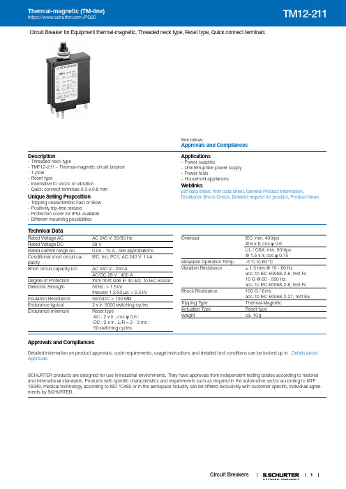
1Circuit Breaker for Equipment thermal-magnetic, Threaded neck type, Reset type, Quick connect terminalsSee below:Approvals and CompliancesDescription- Threaded neck type- TMF12-211 - Thermal-magnetic circuit breaker - 1-pole - Reset type- Insensitive to shock or vibration- Quick connect terminals 6.3 x 0.8 mmUnique Selling Proposition- Tripping characteristic Fast or Slow - Positively trip-free release- Protection cover for IP54 available - Different mounting possibilitiesApplications- Power supplies- Uninterruptible power supply - Power tools- Household appliancesWeblinkspdf data sheet , html data sheet , General Product Information ,Distributor-Stock-Check , Detailed request for product , Product NewsT echnical DataRated Voltage AC AC 240 V: 50/60 Hz Rated Voltage DC28 VRated current range AC 0.05 - 15 A , see approbations Conditional short circuit ca-pacityIEC: Inc, PC1, AC 240 V: 1 kA Short circuit capacity Icn AC 240 V : 200 A AC/DC 28 V : 400 ADegree of Protection from front side IP 40 acc. to IEC 60529Dielectric Strength 50 Hz: > 1.5 kVImpulse 1.2/50 μs: > 2.5 kV Insulation Resistance 500 VDC > 100 M ΩEndurance typical 2 x Ir: 5000 switching cycles Endurance minimumReset typeAC : 2 x Ir , cos φ 0.6 :DC : 2 x Ir , L/R = 2 - 3 ms : 50 switching cyclesOverload IEC: min. 40 trips @ 6 x Ir, cos φ 0.6␣UL / CSA: min. 50 trips @ 1.5 x Ir, cos φ 0.75Allowable Operation Temp.-5 °C to 60 °CVibration Resistance± 1.5 mm @ 10 - 60 Hzacc. to IEC 60068-2-6, test Fc 10 G @ 60 - 500 Hzacc. to IEC 60068-2-6, test Fc Shock Resistance 100 G / 6 msacc. to IEC 60068-2-27, test Ea Tripping Type Thermal-Magnetic Actuation Type Reset type Weightca. 10 gApprovals and CompliancesDetailed information on product approvals, code requirements, usage instructions and detailed test conditions can be looked up in Details about ApprovalsSCHURTER products are designed for use in industrial environments. They have approvals from independent testing bodies according to national and international standards. Products with specific characteristics and requirements such as required in the automotive sector according to IATF 16949, medical technology according to ISO 13485 or in the aerospace industry can be offered exclusively with customer-specific, individual agree-ments by SCHURTER.ApprovalsThe approval mark is used by the testing authorities to certify compliance with the safety requirements placed on electronic products. Approval Reference T ype: TM12Approval Logo Certificates Certification Body DescriptionVDE Approvals VDE VDE Certificate Number: 99673UL Approvals UL UL File Number: E71572CSA Approvals CSACSA Certification Record: LR 37712CQC Approvals CQC CCC Certificate Number: 2012010307564275 Product standardsProduct standards that are referencedOrganization Design StandardDescriptionDesigned according to IEC 60934Circuit-breakers for equipment (CBE)Designed according to UL 1077Standard for Supplementary Protectors for Use in Electrical EquipmentDesigned according to GB 17701Circuit-breaker for equipment Application standardsApplication standards where the product can be usedOrganization Design StandardDescriptionDesigned for applications acc.IEC/UL 60950IEC 60950-1 includes the basic requirements for the safety of informationtechnology equipment.CompliancesThe product complies with following Guide LinesIdentification Details Initiator DescriptionCE declaration of conformity SCHURTER AG The CE marking declares that the product complies with the applicablerequirements laid down in the harmonisation of Community legislation onits affixing in accordance with EU Regulation 765/2008.RoHS SCHURTER AG EU Directive RoHS 2011/65/EUChina RoHS SCHURTER AG The law SJ / T 11363-2006 (China RoHS) has been in force since 1 March2007. It is similar to the EU directive RoHS.REACH SCHURTER AG On 1 June 2007, Regulation (EC) No 1907/2006 on the Registration,Evaluation, Authorization and Restriction of Chemicals 1 (abbreviated as"REACH") entered into force.23Dimension [mm]TMx12-211+0.5TMx12-211N+0.54DiagramsTM12-...TM12-...NTM12-...STM12-...SNEffect of ambient temperatureThe units are calibrated for an ambient temperature of +23°C. To determine the rated cur-rent for a lower or higher ambient temperature, use a correction factor (typical value) from1.2, Resulting current = 6.0 A56Time-Current-CurvesT i m e i n S e c o n d s10[ sec ][ min ]Multiple of Rated Current InReference Temperature +23°Config. CodeTM F 12-|1|2|3|A |B |C |-|1.23|The characters are placeholders for the correspondingly keys of selections from the key tables.TM F 12-|1|2|3|A |B |C |-|1.23| = Magnetic release rangeTM |F |12|-| 1 |2|3|A |B |C |-|1.23| = MountingTM |F |12|-|1| 2 |3|A |B |C |-|1.23| = Actuation TypeTM |F |12|-|1|2| 3 |A |B |C |-|1.23| = TerminalTM |F |12|-|1|2|3| A |B |C |-|1.23| = Auxiliary contactTM |F |12|-|1|2|3|A | B |C |-|1.23| = Shunt terminalTM |F |12|-|1|2|3|A |B | C |-|1.23| = Setting indicationTM |F |12|-|1|2|3|A |B |C |-| 1.23 | = Rated currentVariantsPackaging Unit 20 Pcs AccessoriesDescriptionT-Line AccessoriesAccessories to T-LineThe specifications, descriptions and illustrations indicated in this document are based on currentinformation. All content is subject to modifications and amendments. Information furnished is believed25.1.2197。
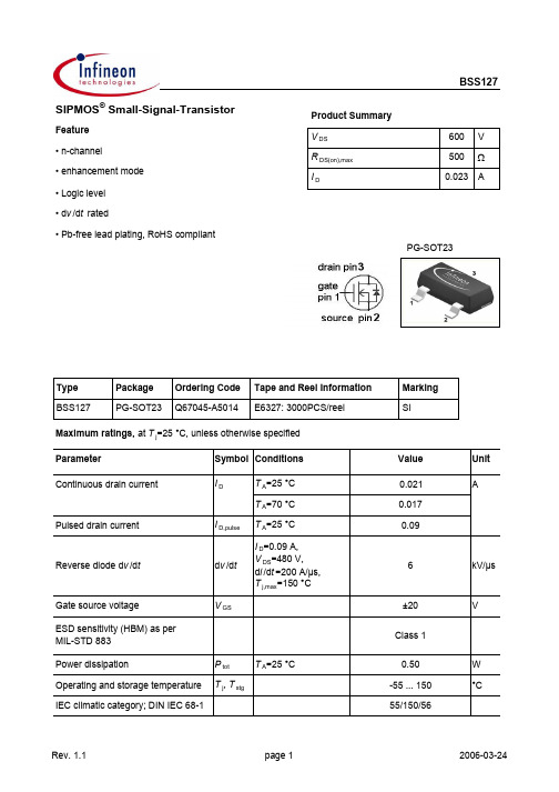
BSS127中文资料
TypeParameter Symbol Conditions Unitmin.typ.max. Thermal characteristicsThermal resistance,junction - minimal footprintR thJA--250K/W Electrical characteristics, at T j=25 °C, unless otherwise specifiedStatic characteristicsDrain-source breakdown voltage V(BR)DSS V GS=0 V, I D=250 µA600--V Gate threshold voltage V GS(th)V DS=0 V, I D=8 µA 1.4 2.0 2.6Drain-source leakage current I D (off)V DS=600 V, V GS=0 V,T j=25 °C--0.1µAV DS=600 V, V GS=0 V,T j=150 °C--10Gate-source leakage current I GSS V GS=20 V, V DS=0 V-10100nADrain-source on-state resistance R DS(on)V GS=4.5 V,I D=0.016 A-330600ΩV GS=10 V, I D=0.016 A-310500Transconductance g fs |V DS|>2|I D|R DS(on)max,I D=0.01 A0.0070.015-SValuesParameterSymbol ConditionsUnitmin.typ.max.Dynamic characteristics Input capacitance C iss -2128pFOutput capacitanceC oss - 2.43Reverse transfer capacitance C rss - 1.0 1.5Turn-on delay time t d(on)- 6.119.0ns Rise timet r -9.714.5Turn-off delay time t d(off)-1421Fall timet f-115170Gate Charge Characteristics Gate to source charge Q gs -0.050.08nCGate to drain charge Q gd - 1.2 1.8Gate charge total Q g - 1.4 2.1Gate plateau voltage V plateau- 3.5-V Reverse DiodeDiode continous forward current I S --0.016ADiode pulse current I S,pulse --0.09Diode forward voltage V SD V GS =0 V, I F =0.016 A, T j =25 °C -0.82 1.2V Reverse recovery time t rr -160240ns Reverse recovery chargeQ rr-13.219.8nC V R =300 V, I F =0.016 A, d i F /d t =100 A/µsT A =25 °CValues V GS =0 V, V DS =25 V, f =1 MHzV DD =300 V,V GS =10 V, I D =0.01 A, R G =6 ΩV DD =400 V, I D =0.01 A, V GS =0 to 10 V1 Power dissipation5 Typ. output characteristics9 Drain-source on-state resistance13 Typ. gate chargePackage Outline:Footprint:Packaging:Published byInfineon Technologies AGBereich KommunikationSt.-Martin-Straße 53D-81541 München© Infineon Technologies AG 1999All Rights Reserved.Attention please!The information herein is given to describe certain components and shall not be considered as warranted characteristics.Terms of delivery and rights to technical change reserved.We hereby disclaim any and all warranties, including but not limited to warranties of non-infringement, regarding circuits, descriptions and charts stated herein.Infineon Technologies is an approved CECC manufacturer.InformationFor further information on technology, delivery terms and conditions and prices, please contact your nearest Infineon Technologies office in Germany or our Infineon Technologies representatives worldwide (see address list).WarningsDue to technical requirements, components may contain dangerous substances.For information on the types in question, please contact your nearest Infineon Technologies office. Infineon Technologies' components may only be used in life-support devices or systems with the expressed written approval of Infineon Technologies if a failure of such components can reasonablybe expected to cause the failure of that life-support device or system, or to affect the safety or effectiveness of that device or system. Life support devices or systems are intended to be implantedin the human body, or to support and/or maintain and sustain and/or protect human life. If they fail,it is reasonable to assume that the health of the user or other persons may be endangered.。
地质水样品总α总β放射性检测技术探讨
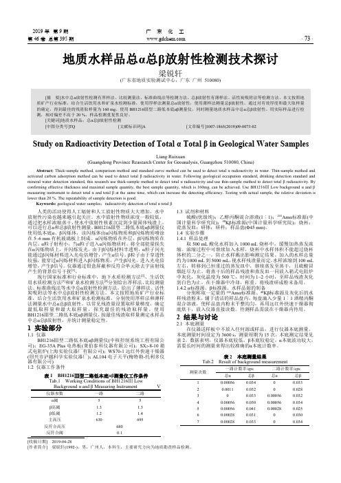
2019年第9期广东化工第46卷总第395期·73·地质水样品总α总β放射性检测技术探讨梁锐轩(广东省地质实验测试中心,广东广州510080)Study on Radioactivity Detection of TotalαTotalβin Geological Water SamplesLiang Ruixuan(Guangdong Province Reasearch Center for Geoanalysis,Guangzhou510080,China) Abstract:Thick-sample method,comparison method and standard curve method can be used to detect totalαradioactivity in water.Thin-sample method and activated carbon adsorption method can be used to detect totalβradioactivity in water.Following geological occupation standard,drinking detection standard and mineral water detection standard,this research use thick-sample method to detect totalαradioactivity and use thin-sample method to detect totalβradioactivity.By confirming effective thickness and maximal sample quantity,the best sample quantity,which is160mg,can be e BH1216ⅢLow backgroundαandβmeasuring instrument to detect totalαand totalβat the same time,which can increase the detecting efficiency.Testing with actual sample,the relative deviation is lower than20%.The repeatability of sample detection is good.Keywords:geological water samples;radioactivity detection of totalαtotalβ人类的活动使得人工辐射和人工放射性物质大大增加,水中放射性污染也越来越引起关注。
三极管 场效应管参数大全

三极管、场效应管参数大说明:三极管标有(达)字即达林顿管;(D)字即带阻尼管。
2SA.2SB是PNP管 2SC.2SD是NPN管. 2管,2S、2SD是低频管.三极管系列型号结构外形参数2N2222NPN TO-9260V 0.8A 0.5W2N2907PNP TO-9260V 0.4A 0.4W2N3055NPN TO-3100V 15A 117W2N3772NPN TO-3100V 30A 150W2N3904NPN TO-9260V 0.2A 0.3W2N3906NPN TO-9240V 0.2A 0.3W2N3907NPN TO-9260V 0.03A 60MHZ2N4126PNP TO-9225V 0.2A 0.3W2N4400NPN TO-9260V 0.6A2N4401NPN TO-9260V 0.6A2N4402PNP TO-9240V 0.6A2N4403PNP TO-9240V 0.6A2N5191NPN TO-12660V 4A 40W2N5192NPN TO-12680V 4A 40W2N5193PNP TO-12640V 4A 40W2N5194PNP TO-12660V 4A 40W2N5195PNP TO-12680V 4A 40W2N5210PNP TO-926V 0.05A2N5401PNP TO-92160V 0.6A 0.3W2N5460PNP TO-9240V 1MA2N5551NPN TO-92180V 0.6A 0.3W2N5609PNP80V 5A 25W Hfe70~1002N5684PNP TO-380V 50A 300W2N5685NPN TO-360V 50A 300W2N5686NPN TO-380V 50A 300W2N6274NPN TO-3120V 50A 250W2N6034PNP达TO-12640V 4A 40W2N6037NPN达TO-12640V 4A 40W2N6277NPN TO-3180V 50A 250W2N6284NPN达TO-3100V 20A 160W2N6286PNP达TO-380V 20A 160W2N6287PNP达TO-3100V 20A 160W2N6338NPN TO-3120V 25A 200W2N6517NPN TO-92350V 0.5A 0.6W2N6520PNP TO-92350V 0.5A 0.6W2N6547NPN TO-3850V 15A 175W2N6576NPN TO-3450V 20A 175W2N6678NPN TO-3650V 20A 175W2N7000N沟道60V 300MA 830MW 3DD15A NPN TO-360V 5A 50W3DD15D NPN TO-3200V 5A 50W3DD15D塑NPN TO-220200V 5A 50W3DD102B NPN TO-3150V 2A 50W3DD102C NPN TO-3150V 2A 50W3DD200NPN TO-3150V 2A 40W3DD207NPN TO-3150V 2A 40W3DD303A NPN TO-3150V 2A 40WBD135NPN TO-12645V 1.5A 12.5W BD136PNP TO-12645V 1.5A 12.5W BD137NPN TO-12660V 1.5A 12.5W BD138PNP TO-12660V 1.5A 12.5W BD139NPN TO-12680V 1.5A 12.5W BD140PNP TO-12680V 1.5A 12.5W BD228NPN TO-12660V 1.5A 12.5W BD234PNP TO-12645V 2A 25WBD235NPN TO-12660V 2A 25WBD236PNP TO-12660V 2A 25WBD237NPN TO-126100V 2A 25WBD238PNP TO-126100V 2A 25WBD239NPN TO-12645V 2A 30WBD241NPN TO-22045V 3A 40WBD242PNP TO-22045V 3A 40WBD243NPN TO-22045V 6A 65WBD244NPN TO-22045V 6A 65WBD330PNP TO12635V 3A 15WBD245NPN TO-22045V 10A 80WBD646PNP达TO-22060V 8A 62.5WBD647NPN达TO-22060V 8A 62.5WBD648PNP达TO-22080V 8A 62.5WBD649NPN达TO-220100V 8A 62.5W BD650PNP达TO-220100V 8A 62.5W BD651NPN达TO-220120V 8A 62.5W BD652PNP达TO-220120V 8A 62.5W BD678PNP达TO-12660V 4A 40WBD679NPN达TO-12680V 4A 40WBD680PNP达TO-12680V 4A 40WBD682PNP达TO-126100V 4A 40WBC327PNP TO-9250V 0.8A 0.6WBC328PNP TO-9230V 0.8A 0.6WBC337NPN TO-9250V 0.8A 0.6WBC338NPN TO-9230V 0.8A 0.6WBC368NPN TO-9220V 1A 0.8WBC369PNP TO-9220V 1A 0.8WBC546NPN TO-9280V 0.2A 0.5WBC547NPN TO-9250V 0.2A 0.5WBC548NPN TO-9230V 0.2A 0.5WBC549NPN TO-9230V 0.2A 0.5WBC550NPN TO-9250V 0.2A 0.5WBC556PNP TO-9280V 0.2A 0.5WBC557PNP TO-9250V 0.2A 0.5WBC558PNP TO-9230V 0.2A 0.5W 150MHZ BC559PNP TO-9230V 0.2A 0.5WBC560PNP TO-9250V 0.2A 0.5WBC635NPN TO-9245V 1A 0.8WBC636PNP TO-9245V 1A 0.8WBC638PNP TO-9260V 1A 0.8WBC640PNP TO-9280V 1A 0.8WBC879NPN达TO-126100V 1A 0.8WBF198NPN TO-9240V 25MA 0.25W BF199NPN TO-9240V 25MA 0.25W BF240NPN TO-9215V 0.1A 0.3WBF241NPN TO-9240V 25MA 0.25W BF324PNP TO-9240V 25MA 0.3WBF420NPN TO-92300V 0.1A 0.8WBF421PNP TO-92300V 0.1A 0.8WBF422NPN TO-92250V 0.1A 0.8WBF423PNP TO-92250V 0.1A 0.83W BF458NPN TO-126250V 0.1A 10WBF459NPN TO-126300V 0.1A 10WBF483NPN TO-92300V 0.5A 0.8WBF485NPN TO-92350V 0.5A 0.6WBF494NPN TO-9230V 0.03A 0.3WBF495NPN TO-9230V 0.03A 0.3WBF869NPN TO-202250V 0.1A 1.8WBF871NPN TO-202300V 0.1A 1.8W BFX85NPN100V 1A 8WBS107N TO-92200V 0.13A 1WBS170N TO-9260V 0.3A 0.6WBU208A NPN TO-31500V 5A 12.5W BU208D NPN D TO-31500V 5A 50WBU290A NPN330V 8A 90WBU326NPN TO-3800V 6A 60W BU406NPN TO-220400V 7A 60W BU406D NPN D TO-220400V 7A 60W BU407NPN TO-220330V 7A 60W BU407D NPN D TO-220330V 7A 60W BU408NPN TO-220400V 7A 60W BU408D NPN D TO-220400V 7A 60W BU508A NPN TOP-3A1500V 7.5A 75W BU415NPN800V 12A 120W BU508D NPN D TOP-3A1500V 7.5A 75W BU508AF NPN TOP-3F1500V 8A 45W BU508DF NPN D TOP-3F1500V 8A 45W BU626A1000V 10A 100W BU806NPN达TO-220400V 8A 60W BU807NPN达TO-22033V 8A 60W BU932R NPN达TO-3500V 15A 150W BU932RD NPN TOP-3F450V 15A 125W BU941NPN达TO-3500V 15A 175W BU1508DX NPN D1500V 10A 125W BU2506AF NPN TOP-3F1500V 5A 45W BU2506DF NPN D TOP-3F1500V 5A 45W BU2507DF NPN D1500V 6A 125W BU2508AF NPN TOP-3F1500V 8A 45W BU2508DF NPN D TOP-3F1500V 8A 125W BU2508AX NPN TOP-3F1500V 8A 45W BU2508DX NPN D TOP-3F1500V 8A 45W BU2520A NPN D TOP-3F800V 8A 125W BU2520AF NPN TOP-3F1500V 10A 45W BU2520DF NPN D TOP-3F1500V 10A 125W BU2520AX NPN TOP-3E1500V 10A 45W BU2520DP NPN D800V 10A 45W BU2520DX NPN D TOP-3E1500V 10A 45W BU2522A NPN D TOP-3E800V 10A 125W BU2522AF NPN TOP-3F1500V 10A 80W BU2522DF NPN D TOP-3F1500V 10A 80W BU2522AX NPN TOP-3E1500V 10A 45W BU2522DX NPN D TOP-3E1500V 10A 45W BU2523AF NPN TOP-3F1500V 10A 80W BU2523DF NPN D TOP-3F1500V 10A 80W BU2523AX NPN TOP-3E1500V 10A 45W BU2525AF NPN TOP-3F1500V 12A 80W BU2525DF NPN D TOP-3F1500V 12A 125W BU2525AX NPN TOP-3E1500V 12A 45WBU2525DX NPN TOP-3E1500V 12A 45W BU2527A NPN D TOP-3E800V 10A 125W BU2527AF NPN TOP-3F1500V 12A 125W BU2527DF NPN D TOP-3F1500V 12A 125W BU2527AX NPN TOP-3E1500V 12A 125W BU2527DX NPN D TOP-3E1500V 12A 125W BUH315NPN TOP-3E1500V 5A 50W BUH315D NPN D TOP-3E1500V 5A 50W BUH515NPN TOP-3E1500V 8A 60W BUH515D NPN D TOP-3E1500V 8A 60W BUH1215NPN TOP-31500V 19A 200W BUH51501500V 5A 50W BUT11A NPN D TO-2201000V 5A 100W BUT11AF NPN TO-220450V 5A 40W BUT11AX NPN TO-220450V 5A 40W BUT12A NPN TO-2201000V 10A 100W BUT12AF NPN TO-220450V 8A 23W BUT18AF NPN TO-220450V 6A 110W BUS12NPN TO-3850V 10A 125W BUS12A NPN TO-31000V 10A 125W BUS13A NPN TO-3850V 15A 175W BUS13A NPN TO-31000V 15A 175W BUS14A NPN TO-3850V 30A 250W BUS14A NPN TO-31000V 30A 250W BUS48NPN TO-3850V 15A 175W BUS48A NPN D TO-31000V 15A 175W BUW11AF NPN TO-31000V 5A 100W BUW12A NPN TO-31000V 10A 125W BUW12AF NPN TO-31000V 8A 125W BUW13A NPN D TO-31000V 15A 150W BUW13AF NPN TO-31000V 15A 175W BUW13F NPN TO-31000V 15A 175W BUW14NPN450V 0.5A 20W BUW14AF NPN TO-31000V 20A 175W BUW26NPN TO-3800V 10A 125W BUW35NPN TO-3800V 10A 125W BUW36NPN TO-3900V 10A 125W BUW45NPN TO-3800V 15A 175W BUW46NPN TO-3900V 15A 175W BUW48A NPN TO-3120V 30A 150W BUW48AF NPN TO-31000V 60A 150W BUV20NPN TO-3125V 50A 250W BUV21NPN TO-3200V 50A 250WBUV22NPN TO-3250V 50A 250W BUV28NPN D TO-3400V 12A 85W BUV28A NPN TO-220200V 12A 85W BUV37NPN 达TOP-3400V 15A 100W BUV46A NPN TO-220400V 6A 70W BUV46C NPN TO-220400V 6A 70W BUV47A NPN D TO-31000V 8.5A 120W BUV48A NPN TOP-3700V 15A 150W BUV90NPN达TOP-3400V 12A 125W BUX20NPN TO-3160V 50A 250W BUX21NPN TO-3250V 40A 250W BUX22NPN TO-3300V 40A 250W BUX48A NPN TO-31000V 7A 150W BUX48B NPN TO-31100V 10A 175W BUX48C NPN TO-31200V 15A 175W BUX81NPN TO-31000V 10A 125W BUX85NPN TO-2201000V 2A 40W BUX87NPN TO-1261000V 0.5A 20W BUX98NPN TO-3850V 30A 250W BUX98A NPN TO-31000V 30A 250W BUX98C NPN TO-31200V 30A 250W YTFP250N200V 30A 150W BUY71NPN TO-32200V 2A 40W BDX33NPN达TO-220100V 10A 70W BDX34C PNP达TO-220100V 10A 70W BDX53C NPN达TO-220100V 8A 60W BDX54C PNP达TO-220100V 8A 60W HPA100NPN TO-3PL1500V 10A 150W HPA150NPN TO-3PL1500V 10A 150W BFR91NPN40A15V 0.03A 0.18W BFR96S NPN40A20V 0.1A 0.7W CS8050NPN TO-9230V 1A 0.6W CS8550PNP TO-9230V 1A 0.6W CS9011NPN TO-9235V 20MA 0.15W CS9012PNP TO-9240V 0.1A 0.5W CS9013NPN TO-9240V 0.1A 0.5W CS9014NPN TO-9230V 50MA 0.3W CS9015PNP TO-9230V 50MA 0.3W CS9016NPN TO-9230V 20MA 0.2W CS9018NPN TO-9230V 20MA 0.2W MJ2955PNP TO-360V 15A 150W MJ10001PNP TO-3500V 20A 150W MJ10004PNP TO-3450V 20A 175WMJ10005NPN TO-3500V 20A 175W MJ10009NPN TO-3700V 20A 175W MJ10012NPN TO-3550V 10A 175W MJ10014NPN TO-3700V 10A 175W MJ10015NPN TO-3600V 50A 250W MJ10016NPN TO-3700V 50A 250W MJ10024NPN TO-31000V 20A 250W MJ10025NPN TO-31200V 20A 250W MJ11015PNP TO-3120V 30A 200W MJ11016NPN TO-3120V 30A 200W MJ11032NPN TO-3120V 50A 300W MJ11033PNP TO-3120V 50A 300W MJ12005NPN TO-31500V 8A 100W MJ13081NPN TO-3750V 8A 150W MJ13333NPN TO-3700V 20A 175W MJ13334NPN TO-3750V 20A 175W MJ13335NPN TO-3800V 20A 175W MJ15003NPN TO-3140V 20A 200W MJ15004PNP TO-3140V 20A 200W MJ15015NPN TO-3140V 20A 200W MJ15016PNP TO-3120V 15A 180W MJ15022NPN TO-3400V 16A 250W MJ15023PNP TO-3400V 16A 250W MJ15024NPN TO-3400V 16A 250W MJ15025PNP TO-3400V 16A 250W MJ13008TO-3MJ13009TO-3MJ4502PNP TO-390V 30A 200W MJ802NPN TO-390V 30A 200W MPSA05NPN TO-9260V 0.5A 0.6W MPSA06NPN TO-9280V 0.5A 0.6W MPSA42NPN TO-92300V 0.5A 0.6W MPSA43NPN TO-92200V 0.5A 0.6W MPSA44NPN TO-92350V 0.5A 0.6W MPSA55PNP TO-9280V 0.5A 0.6W MPSA92PNP TO-92300V 0.5A 0.6W MPSA94PNP TO-92350V 0.5A 0.6W MJE13001NPN TO-92MJE13003NPN TO-126400V 1.5A 40W MJE13005NPN TO220400V 8A 75W MJE13007NPN TO-220400V 4A 80W MJE13009NPN TO-220400V 12A 100W MN650NPN TOP-3AMN651NPN TOP-3ANT407F1500V 5A 60W TIP29C NPN TO-220100V 2A 30W TIP30C PNP TO-220100V 2A 30W TIP31C NPN TO-220100V 3A 40W TIP32C PNP TO-220100V 3A 40W TIP35C NPN TOP-3100V 25A 125W TIP36C PNP TOP-345V 25A 125W TIP41C NPN TO-220100V 6A 65W TIP42C PNP TO-220100V 6A 65W TIP47NPN TO-220250V 1A 40W TIP48NPN TO-220300V 1A 40W TIP49NPN TO-220350V 1A 40W TIP50NPN TO-220400V 1A 40W TIP120NPN达TO-22060V 5A 65W TIP121NPN达TO-22080V 5A 65W TIP122NPN达TO-220100V 5A 65W TIP127PNP达TO-220100V 5A 65W TIP132PNP达TO-220100V 8A 70W TIP137PNP达TO-220100V 8A 70W TIP142大NPN达TOP-3100V 10A 125W TIP142小NPN达TO-220100V 10A 125W TIP147大NPN达TOP-3100V 10A 125W TIP147小NPN TO-220100V 10A 125W TIP2955大PNP TOP-3100V 15A 90W TIP2955小PNP TO-22070V 10A 75W TIP3055大NPN TOP-3100V 15A 90W TIP3055小NPN TO-22070V 10A 75W DTC124ES NPN RB=RBE=22K50V 100MA KAA11508NPN1500V 6A 50W THD25HI NPN1500V 20A 57W ULBM10NPN36V 2.5A 58W FS407D NPN D500V 7A 60W FS7KM250V 7A 30W F18004NPN1500V 5A 80WUN 2211NPN50V 100MARB=RBE=10K(RB基极电阻,RBE为基射之间电阻).UN2212NPN50V 100MARB=RBE=22K(RB基极电阻,RBE为基射之间电阻).UN2213NPN50V 100MARB=RBE=47K(RB基极电阻,RBE为基射之间电阻)2SA114PNP锗TO-9234V 10MA 20MHZ 2SA115PNP锗TO-9234V 10MA 20MHZ 2SA124PNP锗TO-9215V 2MA 120MHZ 2SA144PNP锗TO-9215V 10MA 15MHZ 2SA536PNP TO-9250V 0.7A 0.5W2SA539PNP TO-9260V 0.2A 0.25W 2SA562PNP TO-9230V 0.4A 0.3W2SA564PNP TO-9225V 0.1A 0.25W 2SA608PNP TO-9230V 0.1A 180MHZ 2SA634PNP TO-20240V 2A 10W2SA671PNP TO-22050V 3A 25W2SA673PNP TO-9235V 0.5A 0.4W2SA683PNP TO-9230V 1A 0.75W2SA684PNP TO-9260V 1A 0.75W2SA708PNP TO-9280V 0.7A 0.8W2SA715PNP TO-12635V 1.5A 10W2SA720PNP TO-9250V 0.5A 0.4W2SA733PNP TO-9250V 0.1A 180MHZ 2SA768PNP TO-22060V 4A 30W2SA769PNP TO-22080V 4A 30W2SA817PNP TO-9270V 0.75A 0.6W 2SA838PNP TO-9230V 0.03A300MHZ 2SA844PNP TO-9255V 0.1A 200MHZ 2SA893PNP TO-9290V 0.05A 120MHZ 2SA916PNP TO-92160V 0.05A 0.8W 2SA928PNP TO-9220V 1A 0.25W2SA933PNP TO-9250V 0.1A 140MHZ 2SA934PNP TO-9240V 0.7A 0.75W 2SA935PNP TO-9280V 0.7A 0.75W 2SA940PNP TO-220130V 0.8A 25W2SA949PNP TO-92150V 0.05A 0.8W 2SA950PNP TO-9230V 0.8A 0.6W2SA952PNP TO-9230V 0.7A 0.6W2SA953PNP TO-9260V 0.3A 0.6W2SA954PNP TO-9280V 0.3A 0.6W2SA959PNP TO-3100V 10A 150W 2SA965PNP TO-92120V 0.8A 0.9W 2SA966PNP TO-9230V 1.5A 0.9W2SA984PNP TO-9260V 0.5A 0.5W2SA988PNP TO-92120V 0.05A 100MHZ2SA992PNP TO-92120V 0.05A 0.25W2SA1013PNP TO-92160V 1A 0.9W2SA1015PNP TO-9250V 0.15A 0.4W2SA1018PNP TO-92250V 0.07A 0.75W2SA1020PNP TO-9250V 2A 0.9W2SA1038PNP TO-92120V 0.05A 0.3W2SA1048PNP TO-9250V 0.15A 0.2W2SA1061PNP TO-220100V 6A 70W2SA1091PNP TO-92300V 0.1A 0.4W2SA1147PNP TO-92180V 15A 150W2SA1150PNP TO-9235V 0.8A 0.3W2SA1152PNP TO-9280V 0.3A 0.6W2SA1156PNP TO-126400V 0.5A 10W2SA1160PNP TO-9220V 2A 0.9W2SA1175PNP TO-9260V 0.1A 0.3W2SA1198PNP TO-9280V 0.05A 0.4W2SA1199PNP TO-9250V 0.7A 0.4W2SA1205PNP TO-9270V 12A 100W2SA1207PNP TO-92180V 0.07A 0.6W2SA1208PNP TO-92180V 0.07A 0.9W2SA1209PNP TO-126180V 0.07A 10W2SA1242PNP35V 5A 1W 170MHZ 2SA1266PNP TO-9250V 0.15A 0.4W2SA1267PNP TO-9250V 0.15A 0.2W2SA1268PNP TO-92120V 0.1A 0.3W2SA1270PNP TO-9235V 0.5A 0.5W2SA1271PNP TO-9235V 0.8A 0.6W2SA1273PNP TO-9230V 2A 1W2SA1276PNP TO-22030V 3A 10W2SA1282PNP TO-9220V 2A 0.9W2SA1286PNP TO-9230V 1.5A 0.9W2SA1296PNP TO-9230V 2A 0.75W2SA1300PNP TO-9220V 2A 0.75W2SA1309PNP TO-9220V 0.1A 0.3W2SA1317PNP TO-9260V 0.2A 0.3W2SA1318PNP TO-9260V 0.2A 0.6W2SA1328PNP TO-9260V 1A 40W2SA1370PNP TO-92200V 0.1A 1W2SA1371PNP TO-92300V 0.1A 1W2SA1390PNP TO-9235V 0.5A 0.3W 120MHZ 2SA1451PNP TO-22060V 12A 30W2SA1486PNP TO-12660V 1A 15W2SA1515PNP TO-9240V 1A 0.5W2SA1538PNP TO-126120V 0.2A 8W 2SA1564PNP TO-9250V 0.1A 0.3W 2SA1568PNP TO-22060V 12A 35W 2SA1583PNP TO-9260V 0.1A 1W2SA1614PNP TO-92400V 0.5A 25W 2SA1619PNP TO-9230V 1A 1W2SA1624PNP TO-92250V 0.1A 0.5W 2SA1625PNP TO-92400V 0.5A 0.75W 2SA1668PNP TO-220F200V 2A 25W 2SA1680PNP TO-9260V 2A 0.9W2SA1758PNP TO-220F100V 12A 30W 2SA1767PNP TO-92300V 0.07A 0.75W 2SA1775PNP TO-126400V 0.5A 10W 2SA1778PNP TO-9215V 0.05A 0.25W 2SA1784PNP TO-92400V 0.2A 1W 2SA1884PNP TO-92400V 1A 0.9W 2SB511PNP TO-22035V 1.5A 10W 2SB535PNP锗TO-22035V 1A 5W2SB536PNP TO-220140V 1.5A 20W 2SB544PNP TO-9225V 1A 0.75W 2SB546PNP TO-220200V 2A 20W 2SB553PNP TO-22070V 7A 40W2SB554PNP TO-220160V 15A 150W 2SB561PNP TO-9225V 0.7A 0.5W 2SB562PNP TO-9225V 1A 0.9W 2SB566PNP TO-22050V 4A 40W2SB595PNP TO-220100V 5A 40W 2SB596PNP TO-22080V 4A 30W2SB598PNP TO-9225V 1A 0.5W2SB649PNP TO-126180V 1.5A 1W 2SB673PNP达TO-220100V 7A 40W 2SB674PNP达TO-22080V 7A 40W2SB689PNP TO-220100V 4A 40W 2SB703PNP TO-220100V 4A 40W 2SB707PNP TO-22080V 7A 40W2SB734PNP TO-12660V 1A 1W2SB739PNP TO-9260V 2A 0.9W2SB744PNP TO-12670V 3A 10W2SB761PNP TO-22060V 3A 35W2SB764PNP TO-9260V 1A 0.9W2SB772PNP TO-12640V 3A 10W2SB774PNP TO-9230V 0.1A 0.25W 2SB795PNP达TO-12680V 1.5A 10W2SB810PNP TO-12630V 0.7A 0.35W 2SB826PNP TO-22060V 12A 40W 2SB834PNP TO-22060V 3A 30W 2SB859PNP TO-220100V 4A 40W 2SB861PNP TO-220100V 2A 30W 2SB889PNP TO-12680V 0.7A 5W 2SB891PNP TO-12640V 2A 5W 2SB892PNP TO-9260V 2A 1W 2SB926PNP TO-9230V 2A 0.75W 2SB927PNP TO-9230V 2A 1W 2SB928PNP TO-126200V 2A 30W 2SB940PNP TO-220F200V 2A 30W 2SB941PNP TO-220F60V 3A 35W 2SB950PNP达TO-220F60V 4A 40W 2SB951PNP达TO-220F60V 8A 45W 2SB1007PNP TO-12680V 0.7A 10W 2SB1008PNP达TO-12640V 2A 10W 2SB1009PNP TO-12640V 2A 10W 2SB1012PNP达TO-126120V 1.5A 8W 2SB1013PNP TO-9220V 2A 0.7W 2SB1014PNP TO-9260V 1A 0.7W 2SB1015PNP TO-220F60V 3A 20W 2SB1023PNP达TO-220F60V 3A 25W 2SB1068PNP TO-9220V 2A 0.75W 2SB1096PNP TO-220F20V 2A 25W 2SB1116PNP TO-9260V 1A 0.75W 2SB1135PNP TO-22060V 7A 30W 2SB1156PNP TO-22060V 12A 30W 2SB1165PNP TO-12660V 5A 20W 2SB1166PNP TO-12660V 8A 20W 2SB1167PNP TO-126120V 3A 20W 2SB1168PNP TO-126120V 4A 20W 2SB1214PNP达TO-12680V 3A 15W 2SB1223PNP达TO-220F70V 4A 20W 2SB1236PNP TO-126120V 1.5A 1W 2SB1237PNP TO-12640V1A 1W2SB1239PNP达TO-12640V 2A 1W 2SB1284PNP达TO-220F100V 10A 35W 2SB1286PNP达TO-220F100V 2A 25W 2SB1287PNP达TO-220F100V 2A 20W 2SB1331PNP TO-12660V 0.5A 0.6W 2SB1326PNP TO-9230V 5A 1W 2SB1329PNP TO-12632V 1A 1.2W2SB1366PNP TO-220F20V 5A 2W2SB1370PNP TO-220F60V 3A 30W2SB1375PNP TO-220F60V 3A 25W2SB1376PNP TO-9250V 0.1A 1W2SB1406PNP达TO-9280V 1.5A 1W2SB1413PNP TO-12630V 1A 1.5W2SB1423PNP TO-12620V 5A 10W2SB1425PNP TO-9220V 2A 1W2SB1548PNP TO-220F2SB1565PNP TO-220F60V 3A 25W2SB1566PNP50V 3A 25W2SB1569PNP TO-220F120V 1.5A 20W2SB1682PNP2SB1978PNP2SC124NPN TO-9240V 0.025A 200MHZ 2SC144NPN TO-9250V 0.2A 450MHZ 2SC317NPN TO-9270V 0.1A 240MHZ 2SC368NPN TO-92250V 0.1A 150MHZ 2SC380NPN TO-9235V 0.03A 250MHZ 2SC388A NPN TO-9225V 0.02A f>300MHZ 2SC458NPN TO-9230V 0.1A 230MHZ 2SC460NPN TO-9230V 0.1A 230MHZ 2SC535NPN TO-9230V 0.02A 700MHZ 2SC761NPN TO-9230V 0.02A 675MHZ 2SC790NPN TO-9250V 3A 25W2SC829NPN TO-9230V 0.03A 230MHZ 2SC930NPN TO-9215V 0.03A 300MHZ 2SC945NPN TO-9260V 0.1A 250MHZ2SC979NPN TO-9270V 0.1A 0.3W Ft=250MHZ2SC1008NPN TO-9280V 0.7A 0.8W2SC1026NPN TO-9225V 0.025A 200MHZ 2SC1047NPN TO-9230V 0.015A 650MHZ 2SC1061NPN TO-22050V 3A 25W2SC1070NPN TO-9230V 0.02A 900MHZ 2SC1106NPN TO-3350V 3A 80W2SC1114300V 4A 100W2SC1127NPN TO-220180V 0.1A 7.9W 2SC1162NPN TO-12635V 2.5A 10W2SC1170NPN TO-31200V 3.5A 50W 2SC1172NPN TO-31500V 5A 50W2SC1173NPN TO-22030V 3A 10W2SC1202NPN2SC1213NPN TO-9235V 0.5A 0.4W2SC1279NPN TO-92180V 0.05A 0.25W 2SC1308NPN TO-31500V 7A 50W2SC1309NPN TO-31200V 5A 80W2SC1318NPN TO-9260V 0.5A 0.4W2SC1325NPN TO-31500V 6A 80W2SC1327NPN TO-9235V 0.05A 250MHZ 2SC1328NPN TO-9235V 0.05A 250MHZ 2SC1348NPN TO-31000V 4A 125W 2SC1358NPN TO-31400V 4.5A 50W 2SC1359NPN TO-9230V 0.03A 300MHZ 2SC1360NPN TO-9250V 0.05A 500MHZ 2SC1383NPN TO-9230V 1A 0.75W2SC1384NPN TO-9260V 1A 0.75W2SC1390NPN TO-9220V 0.09A 0.2W 2SC1473NPN TO-92250V 0.07A 0.6W 2SC1501NPN TO-126300V 0.1A 10W2SC1505NPN TO-220300V 0.2A 15W2SC1507NPN TO-220300V 0.2A 15W2SC1514NPN TO-202300V 0.1A 1.25W 2SC1519NPN TO-202250V 0.2A 10W2SC1565NPN TO-126150V 0.25A 10W 2SC1566NPN TO-126250V 0.1A 4W2SC1569NPN TO-220300V 0.15A 1.5W 2SC1573NPN TO-92250V 0.07A 0.6W 2SC1574NPN TO-9220V 0.03A 4.5GHZ 2SC1579NPN TO-3500V 15A 150W 2SC1625NPN TO-220100V 1A 15W2SC1626NPN TO-22080V 0.7A 15W2SC1627NPN TO-9270V 0.2A 150MHZ 2SC1641NPN TO-9240V 0.15A 0.3W 2SC1651NPN40A210V 0.03A 0.25W 2SC1661NPN TO-9220V 0.08A 7GHZ 2SC1669NPN TO-220150V 1.5A 25W2SC1674NPN TO-9230V 0.02A 600MHZ 2SC1676NPN40A50V 3A 300MHZ 2SC1685NPN TO-9260V 0.1A 150MHZ 2SC1709NPN TO-9230V 0.3A 0.3W2SC1719NPN TO-92150V 0.05A 130MHZ 2SC1720NPN TO-92150V 0.05A 130MHZ 2SC1722NPN TO-92300V 0.2A 15W2SC1740NPN TO-9220V 32MA 180MHZ 2SC1755NPN TO-220300V 0.2A 15W2SC1756NPN TO-220300V 0.2A 15W2SC1757NPN TO-220300V 0.2A 15W2SC1758NPN TO-202300V 0.1A 10W2SC1767NPN2SC1815NPN TO-9260V 0.15A 0.4W2SC1819NPN TO-220300V 0.1A 15W2SC1826NPN TO-22080V 4A 30W2SC1841NPN TO-92120V 0.05A 0.25W2SC1842NPN TO-126 40V 0.1A 0.25W2SC1845NPN TO-92120V 0.05A 110MHZ 2SC1846NPN TO-12645V 1A 1.2W2SC1852NPN TO-9260V 0.5A 0.6W2SC1875NPN TO-31500V 3.5A 50W2SC1892NPN TO-31500V 2.5A 50W2SC1895NPN TO-31500V 6A 50W2SC1905NPN TO-220350V 0.2A 15W2SC1906NPN TO-9230V 0.05A 1GHZ2SC1907NPN TO-9230V 0.05A 1.1GHZ 2SC1908NPN TO-9230V 0.03A 200MHZ 2SC1921NPN TO-92250V 0.05A 0.6W2SC1922NPN TO-31500V 2.5A 50W2SC1923NPN TO-9240V 0.02A 500MHZ 2SC1942NPN TO-31500V 3A 50W2SC1954NPN TO-9220V 0.15A 0.5W2SC1959NPN TO-9235V 0.5A 0.5W2SC1964NPN TO-220F80V 3.5A 12.5W2SC1969NPN TO-22060V 6A 20W2SC1971NPN TO-22035V 2A 12.5W 175MHZ 2SC1972NPN TO-22035V 3.5A 25W 175MHZ 2SC1973NPN TO-9250V 0.5A 1W2SC1984NPN达TO-220100V 3A 30W2SC2001NPN TO-9230V 0.7A 0.6W2SC2002NPN TO-9260V 0.3A 0.6W2SC2003NPN TO-9280V 0.3A 0.6W2SC2026NPN TO-9230V 0.05A 2GHZ2SC2027NPN TO-31500V 5A 50W2SC2058NPN TO-9240V 0.05A 300MHZ 2SC2060NPN TO-9240V 0.7A 150MHZ2SC2061NPN TO-9280V 0.7A 150MHZ2SC2068NPN TO-202300V 0.05A 1.5W2SC2071NPN TO-126250V 0.05A 1W2SC2073NPN TO-220150V 1.5A 25W2SC2075NPN TO-22080V 4A 10W2SC2078NPN TO-22080V 3A 10W2SC2085NPN TO-220300V 0.1A 10W 2SC2120NPN TO-9230V 0.8A 0.5W 2SC2121NPN TO-3750V 3A 50W2SC2147NPN TO-3400V 50A 200W 2SC2166NPN TO-220750V 4A 12.5W 2SC2204NPN TO-3800V 30A 250W 2SC2224NPN TO-220200V 0.2A 10W 2SC2228NPN TO-92160V 0.05A 0.75W 2SC2229NPN TO-92200V 0.05A 0.8W 2SC2230NPN TO-92200V 0.1A 0.8W 2SC2233NPN TO-220200V 4A 40W2SC2235NPN TO-92120V 0.8A 0.9W 2SC2236NPN TO-9230V 1.5A 0.9W 2SC2240NPN TO-92120V 0.1A 100MHZ 2SC2246NPN TO-3450V 15A 100W 2SC2250NPN TO-3大450V 30A 200W 2SC2258NPN TO-126250V 0.1A 1W2SC2271NPN TO-92300V 0.1A 0.75W 2SC2274NPN TO-9260V 0.5A 0.5W 2SC2279NPN TO-220300V 0.1A 10W 2SC2300NPN TO-9250V 1A 0.5W2SC2306NPN TO-3450V 15A 150W 2SC2307NPN TOP-3A500V 12A 100W 2SC2324NPN达TO-12660V 1A 9W2SC2330NPN达TO-9238V 6A 20W2SC2331NPN TO-220150V 2A 15W2SC2335NPN达TO-220500V 7A 40W2SC2356NPN达TO-3500V 10A 100W 2SC2369NPN达TO-9225V 0.07A 4.5GHZ 2SC2371NPN TO-126300V 0.1A 10W 2SC2373NPN TO-220200V 7.5A 40W 2SC2383NPN TO-92160V 1A 0.9W2SC2456NPN TO-126300V 0.1A 10W 2SC2458NPN TO-9250V 0.15A 0.2W 2SC2481NPN TO-126150V 1.5A 20W 2SC2482NPN TO-92300V 0.1A 0.9W 2SC2500NPN TO-9230V 2A 0.9W2SC2535NPN TO-220500V 5A 40W2SC2551NPN TO-92300V 0.1A 0.4W 2SC2553NPN TO-220500V 5A 40W2SC2562NPN TO-22060V 5A 25W2SC2564NPN MT200140V 12A 120W2SC2568NPN TO-126300V 0.2A 10W 2SC2571NPN TOP-3A100V 10A 95W 2SC2577NPN TOP-3A120V 6A 60W 2SC2581NPN TOP-3E200V 10A 100W 2SC2594NPN TO-12640V 5A 10W 2SC2603NPN TO-9250V 0.2A 0.3W 2SC2610NPN TO-92300V 0.1A 0.8W 2SC2611NPN TO-126300V 0.1A 1.25W 2SC2625NPN TOP-3A450V 10A 80W 2SC2634NPN TO-9260V 0.1A 0.4W 2SC2637NPN TO-92300V 0.1A2SC2655NPN TO-9260V 2A 0.9W f>100MHZ2SC2668NPN TO-9240V 0.02A 550MHZ 2SC2676NPN TO-12680V 10MA2SC2688NPN TO-126300V 0.2A 10W 2SC2707NPN TO-3180V 15A 150W 2SC2717NPN TO-9230V 0.05A 0.3W 2SC2719NPN TO-9280V 0.3A 0.6W 2SC2750NPN TOP-3A150V 15A 100W 2SC2773NPN MT200200V 15A 150W 2SC2774NPN MT200200V 17A 200W 2SC2785NPN TO-9260V 0.1A 0.3W 2SC2787NPN TO-9250V 0.03A 250MHZ 2SC2792NPN TOP-3A850V 2A 80W2SC2810NPN TO-220500V 7A 50W2SC2837NPN TOP-3A150V 10A 100W 2SC2878NPN TO-9250V 0.3A 0.4W 2SC2898NPN TO-220500V 8A 50W2SC2899NPN TO-126500V 0.5A 10W 2SC2901NPN TO-9240V 0.2A2SC2910NPN TO-92180V 0.07A 0.9W 2SC2911NPN TO-92180V 0.14A 10W 2SC2930NPN TO-3500V 30A 200W 2SC2958NPN TO-126160V 0.5A 1W2SC2979NPN TO-220900V 3A 40W2SC3026NPN1700V 5A 50W 2SC3038NPN TO-220500V 4A 40W2SC3039NPN TO-220500V 7A 50W2SC3050NPN TP-31200V 5A 150W 2SC3058NPN TO-3600V 30A 200W 2SC3063NPN TO-126300V 0.1A 1.2W 2SC3068NPN TO-9230V 0.3A 0.6W2SC3086NPN TO-220800V 3A 40W2SC3089NPN TOP-3A800V 7A 80W2SC3114NPN60V 0.15A 100MHZ 2SC3148NPN TO-220900V 3A 40W2SC3150NPN TO-220900V 3A 50W2SC3152NPN TOP-3A900V 3A 80W2SC3153NPN TOP-3A900V 6A 100W 2SC3158NPN TO-220F500V 7A 60W2SC3159NPN TO-220F500V 10A 80W 2SC3169NPN TO-220F500V 2A 25W2SC3178NPN TO-220F1200V 2A 60W 2SC3190NPN TO-9235V 0.1A 0.4W 2SC3192NPN TO-9235V 0.05A 0.3W 2SC3195NPN TO-9240V 0.02A 0.1W 2SC3198NPN TO-9260V 0.15A 0.4W 2SC3199NPN TO-9250V 0.15A 0.2W 2SC3200NPN TO-92120V 0.1A 0.3W 2SC3203NPN TO-9235V 0.8A 0.6W 2SC3204NPN TO-9235V 0.8A 0.3W 2SC3205NPN TO-9230V 2A 1W2SC3206NPN TO-92200V 0.05A 0.5W 2SC3209NPN TO-126300V 0.2A 0.9W 2SC3220NPN TOP-3A230V 10A 100W 2SC3230NPN TO-220300V 3A 10W2SC3231NPN TO-220200V 4A 40W2SC3258NPN TO-220100V 5A 25W2SC3260NPN达TOP-3A100V 5A 25W2SC3261NPN达TO-220F800V 3A 50W2SC3269NPN达TO-126300V 0.1A 0.75W 2SC3271NPN达TO-126300V 0.1A 5W2SC3272NPN TO-126300V 0.1A 10W 2SC3300NPN达TOP-3A100V 15A 100W 2SC3303NPN达TO-126100V 5A 20W2SC3306NPN达TOP-3A500V 10A 100W 2SC3307NPN达TOP-3A900V 10A 150W 2SC3310NPN达TO-220F500V 5A 40W2SC3311NPN达TO-9230V 0.1A 0.3W 2SC3330NPN达TO-9260V 0.2A 0.3W 2SC3331NPN达TO-9260V 0.2A 0.5W 2SC3355NPN达TO-9220V 0.1A 0.6W 2SC3356NPN达贴片20V 0.1A 0.2W 2SC3358NPN达40A20V 0.1A 0.25W 2SC3399NPN达TO-9250V 0.1A 0.3W2SC3400NPN达TO-9250V 0.1A 0.3W 2SC3415NPN达TO-92300V 0.1A 0.6W 2SC3417NPN达TO-126300V 0.1A 1.2W 2SC3421NPN达TO-126120V 1A 10W 2SC3422NPN达TO-12640V 3A 10W 2SC3447800V 5A 50W 2SC3457NPN1100V 3A 50W 2SC3459NPN1100V 4.5A 90W 2SC3460NPN1100V 6A 100W 2SC3461NPN TO-31100V 8A 120W 2SC3467NPN达TO-92200V 0.1A 1W 2SC3468NPN达TO-92300V 0.1A 1W 2SC3481NPN D TO-31500V 5A 120W 2SC3482NPN D TOP-3A1500V 6A 120W 2SC3486NPN D TOP-3A1500V 6A 120W 2SC34911000V 4A 60W 2SC3497NPN500V 6A 30W 2SC3498NPN TO-3PL500V 30A 150W 2SC3499NPN TO-3PL500V 30A 150W 2SC4199NPN TO-3PL1400V 10A 100W 2SC3502NPN TO-126200V 0.1A 5W 2SC3503NPN TO-126300V 0.1A 7W 2SC3505NPN TOP-3A900V 6A 80W 2SC3506NPN TOP-3F1000V 3A 70W 2SC3507NPN TOP-3F1000V 5A 80W 2SC3552NPN TOP-3A1100V 12A 150W 2SC3679NPN TOP-3A900V 5A 100W 2SC3685NPN TOP-3A1500V 6A 120W 2SC3686NPN TOP-3A1500V 7A 120W 2SC3687NPN TOP-3A1500V 8A 150W 2SC3688NPN D TOP-3A1500V 10A 150W 2SC3714NPN500V 20A 200W 2SC3738NPN TOP-3A1200V 10A 175W 2SC3783NPN TOP-3A900V 5A 100W 2SC3784NPN达TO-12650V 1.2A 20W 2SC3789NPN TO-12630V 0.1A 7W 2SC3807NPN TO-12630V 2A 15W 2SC3821NPN TO-126450V 5A 40W 2SC3830NPN TO-220600V 6A 50W 2SC3832NPN TO-220500V 7A 50W 2SC3833NPN TO-220500V 12A 100W 2SC3834NPN TO-220200V 7A 50W 2SC3843NPN TOP-3A600V 10A 75W2SC3845NPN TO-31500V 5A 120W 2SC3846NPN TOP-3F1200V 6A 80W 2SC3847NPN TOP-3F1200V 10A 80W 2SC3848NPN TO-9225V 0.2A 500MHZ 2SC3851NPN TO-220F80V 4A 25W2SC3852NPN TO-12680V 3A 25W2SC3883NPN TOP-3A1400V 7A 50W 2SC3884NPN TOP-3E1400V 6A 50W 2SC3886NPN TOP-3E1400V 8A 50W 2SC3889NPN2-16D1400V 8A 80W 2SC3893A NPN TOP-3E1400V 8A 50W 2SC3895NPN TOP-3E1500V 7A 60W 2SC3897NPN TOP-3E1500V 10A 70W 2SC3941NPN TO-32300V 0.07A 1W 2SC3979NPN TO-220F900V 3A 40W 2SC3989NPN TO-3PL800V 25A 200W 2SC3994NPN TO-3PL1100V 25A 300W 2SC3995NPN TO-3PL1500V 12A 180W 2SC3997NPN D TO-3PL1500V 15A 250W 2SC3998NPN TO-3PL1500V 25A 250W 2SC4016NPN TO-9240V 0.5A 0.3W 2SC4019NPN TO-92300V 0.1A 10W 2SC4023NPN TOP-3A1500V 10A 130W 2SC4046NPN TO-126120V 0.2A 8W 2SC4054NPN TO-220F600V 5A 30W 2SC4055NPN TO-220600V 8A 60W 2SC4056NPN TO-220600V 8A 45W 2SC4075NPN TO-220F300V 0.2A 10W 2SC4096NPN TO-3PL1400V 10A 150W 2SC4106NPN500V 10A 60W 2SC4109NPN TOP-3A500V 16A 140W 2SC4111NPN TO-3PL1500V 10A 150W 2SC4115NPN TO-3PL200V 2A 0.4W2SC4119NPN D TO-3PL 1500V 15A 250W HFE=252SC4119A NPN1500V 10A 100W 2SC4123NPN TOP-3E1500V 15A 60W 2SC4124NPN D1500V 8A 70W 2SC4137NPN TO-12625V 0.1A 400MHZ 2SC4138NPN TOP-3A500V 10A 80W 2SC4139NPN TOP-3A500V 15A 120W 2SC4153NPN TO-220F200V 7A 30W 2SC4161NPN TO-220F500V 7A 30W2SC4231NPN TO-220F800V 2A 30W2SC42351500V 5A 40W 2SC42361500V 5A 50W 2SC4242NPN TO-220450V 7A 40W2SC4237NPN TOP-3Q800V 10A 150W 2SC4256NPN TO-2201500V 0.01A 1.75W 2SC4288NPN TOP-3E1400V 12A 200W 2SC4291NPN TOP-3E1500V 5A 100W 2SC4292NPN TOP-3E1500V 6A 100W 2SC4297NPN TOP-3E500V 12A 75W 2SC4300NPN TOP-3E900V 5A 75W2SC4302NPN TOP-3E900V 5A 75W2SC4308NPN TO-9230V 0.3A 0.6W 2SC4311NPN TO-220900V 6A 40W2SC4367NPN TO-9230V 0.1A 0.6W 2SC4368NPN TO-220150V 1.5A 20W 2SC4418NPN TO-220F500V 5A 30W2SC4422NPN TO-9215V 0.05A 0.4W 2SC4423NPN TOP-3E500V 12A 55W 2SC4424NPN TOP-3E500V 16A 60W 2SC4429NPN TOP-3E1100V 8A 60W 2SC4433NPN TO-22040V 0.05A 0.3W 2SC4454NPN TO-22040V 0.2A 0.3W 2SC4482NPN TO-9260V 5A 1W2SC4493NPN TO-220800V 0.02A 1.65W 2SC4513NPN2SC4517NPN TO-220F550V 3A 30W2SC4544NPN TO-220F300V 0.1A 8W2SC4560NPN TOP-3E1500V 10A 80W 2SC4572NPN TO-220800V 10A 50W 2SC4589NPN TO-3PFM1500V 10A 50W 2SC4596NPN TO-220F100V 2A 25W2SC4621NPN TOP-3F500V 7A 70W2SC4630NPN TO-220F1500V 0.1A 2W 2SC4632NPN TO-220F1500V 0.01A 2W 2SC4634NPN TO-220F1500V 0.01A 2W 2SC4664NPN TO-220F250V 8A 30W2SC4682NPN TO-220F30V 3A 0.9W2SC4706NPN TOP-3A900V 14A 130W 2SC4742NPN TOP-3A1500V 6A 50W 2SC4744NPN TO-3PFM1500V 6A 50W 2SC4745NPN TOP-3E1500V 6A 50W 2SC4746NPN TO-3PFM1500V 8A 50W2SC4747NPN TO-3PFM1500V 10A 50W 2SC4752NPN2SC4755NPN TO-9225V 0.2A 500MHZ 2SC4758NPN TOP-3A1500V 8A 50W 2SC4760NPN TOP-3A900V 14A 130W 2SC4762NPN TOP-3A1500V 7A 50W 2SC4763NPN D TOP-3A1500V 8A 50W 2SC4766NPN D TOP-3A1700V 6A 50W 2SC4767NPN TO-9236V 0.3A 1W2SC4769NPN TOP-3A1500V 7A 60W 2SC4770NPN TOP-3A1500V 7A 60W 2SC4803NPN TO-31500V 5A 50W 2SC4804NPN TO-220F2SC4815NPN TO-220F100V 5A 1.8W2SC4824NPN TO-202120V 0.2A 3W2SC4834NPN TO-220F50V 8A 45W2SC4835NPN15V 0.08A 600MHZ 2SC4896NPN TO-3PFM1700V 15A 100W 2SC4897NPN TO-2PL800V 20A2SC4898NPN TO-220300V 5A 40W2SC4916NPN D TOP-3E1500V 7A 50W 2SC4924NPN TOP-3E800V 10A 70W 2SC4927NPN D TO-3PFM1500V 8A 50W 2SC4953NPN TO-220F2SC5002NPN TOP-3E1500V 7A 80W 2SC5047NPN TO-3PL1600V 25A 250W 2SC5048NPN TOP-3E1500V 12A 50W 2SC5124NPN TOP-3E1500V 10A 100W 2SC5129NPN TOP-3E1500V 10A 50W 2SC5132NPN D TO-3PFM1500V 10A 50W 2SC5142NPN TO-3PL1500V 20A 200W 2SC5143NPN D1700V 10A 50W 2SC5147NPN TO-220F300V 0.1A 10W 2SC5148NPN TOP-3E1500V 8A 50W 2SC5149NPN D TOP-3E1500V 8A 50W 2SC5198NPN D TOP-3A1400V 10A 100W 2SC5207NPN TO-3PFM1500V 10A 50W 2SC5250NPN D TO-3PFM1500V 8A 50W 2SC5251NPN TO-3PFM1500V 12A 50W 2SC5252NPN TO-3PFM1500V 15A 60W 2SC5243NPN TO-3PL1700V 15A 200W 2SC5244NPN TO-3PL1500V 30A 200W 2SC5270NPN TOP-3E。
GE Plastics PC LEXAN

LEXAN 141R is a medium viscosity multi purpose grade and contains a release agent to ensure easy processing. LEXAN 141R is available in transparent, translucent and opaque colours.Standard Unit Value1. Physical PropertiesDensityISO 1183 g/cm³1.20 Melt Volume-Flow Rate (MVR) (300°C/1.2 kg) ISO 1133 cm³/10min. 12.0 Water Absorption 23C/50RH ISO 62 % 0.15 Water Absorption Sat/23C ISO 62 % 0.352. Mechanical PropertiesTensile Modulus (1mm/min)ISO 527-1, -2 MPa 2350 Tensile Stress at Yield (50mm/min) ISO 527-1, -2 MPa 63 Tensile Stress at Break (50mm/min) ISO 527-1, -2 MPa 70 Tensile Strain at Yield (50mm/min) ISO 527-1, -2 % 6.0 Tensile Strain at Break (50mm/min) ISO 527-1, -2 % 110 Flexural Modulus (2mm/min)ISO 178 MPa 2300 Charpy Unnotched Impact Strength (23°C edgewise) ISO 179 kJ/m² No Break Charpy Unnotched Impact Strength (-30°C edgewise) ISO 179 kJ/m² No Break Charpy Notched Impact Strength (23°C, Type 2, Notch C) ISO 179 kJ/m² 35Unnotched Izod Impact Strength (23°C, Type 1) ISO 180 kJ/m² No Break Unnotched Izod Impact Strength (-30°C, Type 1) ISO 180 kJ/m² No Break Notched Izod Impact Strength (23°C, Type 1, Notch A) ISO 180 kJ/m² 12 Notched Izod Impact Strength (-30°C, Type 1, Notch A) ISO 180 kJ/m² 10 Ball Indentation Hardness (H 358/30)ISO 2039-1MPa953. Thermal PropertiesCoefficient of Linear Thermal Expansion, Flow (23 to 80°C) ISO 11359-1,-2 cm/cm/°C 7.0E-005 HDT B (0.45 MPa) Unannealed ISO 75B-1,-2 °C 136 HDT A (1.80 MPa) UnannealedISO 75A-1,-2 °C 125 Vicat Softening Temperature A50 (50°C/h, 10N) ISO 306 °C 153 Vicat Softening Temperature B50 (50°C/h, 50N) ISO 306 °C 141 Vicat Softening Temperature B120 (120°C/h, 50N) ISO 306 °C 142 Thermal ConductivityISO 8302W/m/K0.204. Electrical PropertiesRelative Permittivity (60 Hz) IEC 60250 --2.7 Relative Permittivity (50 Hz) IEC 60250 -- 2.7 Relative Permittivity (1 MHz) IEC 60250 -- 2.7 Dissipation Factor (60 Hz) IEC 60250 -- 0.001 Dissipation Factor (50 Hz) IEC 60250 -- 0.001 Dissipation Factor (1 MHz) IEC 60250 --0.01 Volume Resistivity IEC 60093 Ohm•cm 1 E+015 Surface ResistivityIEC 60093 Ohm 1 E+015 Electric Strength (1mm thickness) IEC 60243-1 kV/mm 15 Electric Strength (in Oil, 1.60mm) IEC 60243-1 kV/mm 27 Electric Strength (in Oil, 3.20mm) IEC 60243-1 kV/mm 17 Comp Track IndexIEC 60112V250h t tp ://ww w.u pm ol d .c omLEXAN 141R is a medium viscosity multi purpose grade and contains a release agent to ensure easy processing. LEXAN 141R is available in transparent, translucent and opaque colours.Standard Unit Value5. Flame CharacteristicsFlame Rating – UL (0.7mm) (E121562) UL 94 classHBFlame Rating – UL (3.0mm) (E121562)UL 94 class HB Limiting Oxygen Index (LOI) ISO 4589-1,-2 % 25 Rel. Temp. Index Mech. w/olmp UL 746 °C 125 Rel. Temp. Index Mech. w/lmp UL 746 °C 125 Rel. Temp. Index Elect.UL 746 °C 1306. Additional PropertiesBall Pressure Test (125 °C ± 2 °C) IEC 60335-1 --PASSES Glow Wire Flammability Index (850 °C)IEC 60695-2-12at 1mmPASSESNotes:The figures in this datasheet are guide values. The values are effected by processing conditions, modifications, additives and environmental conditions and they do not release you from the obligation to check the validity and to undertake tests on your own.This information is based on our present knowledge and experience. The material data is not to be construed as guaranteeing specific properties and the data can not be used to deduce the suitability for a particular application.h t tp ://w ww .u pm o l d .c o m。
FOSAN富信电子 三级管 2SB1260-产品规格书
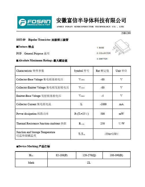
安徽富信半导体科技有限公司ANHUI FOSAN SEMICONDUCTOR TECHNOLOGY CO.,LTD.2SB1260SOT-89Bipolar Transistor双极型三极管▉Features特点PNP General Purpose通用▉Absolute Maximum Ratings最大额定值Characteristic特性参数Symbol符号Rat额定值Unit单位Collector-Base Voltage集电极基极电压V CBO-80V Collector-Emitter Voltage集电极发射极电压V CEO-80V Emitter-Base Voltage发射极基极电压V EBO-5V Collector Current集电极电流I C-1000mA Power dissipation耗散功率P C(T a=25℃)500mW Thermal Resistance Junction-Ambient热阻RΘJA250℃/WJunction and Storage TemperatureT J,T stg-55to+150℃结温和储藏温度■Device Marking产品打标H FE82-180(P)120-270(Q)180-390(R)Mark ZLANHUI FOSAN SEMICONDUCTOR TECHNOLOGY CO.,LTD.2SB1260■ElectricalCharacteristics 电特性(T A =25℃unless otherwise noted 如无特殊说明,温度为25℃)Characteristic 特性参数Symbol 符号Min 最小值Type 典型值Max 最大值Unit 单位Collector-Base Breakdown V oltage集电极基极击穿电压(I C =-50µA ,I E =0)BV CBO -80——V Collector-Emitter Breakdown Voltage集电极发射极击穿电压(I C =-2mA ,I B =0)BV CEO -80——V Emitter-Base Breakdown V oltage发射极基极击穿电压(I E =-50µA ,I C =0)BV EBO -5——V Collector-Base Leakage Current集电极基极漏电流(V CB =-60V ,I E =0)I CBO ——-1µA Emitter-Base Leakage Current发射极基极漏电流(V EB =-4V ,I C =0)I EBO ——-1µADC Current Gain直流电流增益(V CE =-3V ,I C =-100mA)H FE82—390Collector-Emitter Saturation Voltage 集电极发射极饱和压降(I C =-500mA ,I B =-50mA)V CE(sat)——-0.4VBase-Emitter Saturation V oltage基极发射极饱和压降(I C =-500mA ,I B =-50mA)V BE(sat)——-1.2V Base-Emitter On Voltage基极发射极导通电压(V CE =-10V ,I C =-500mA)V BE(on)——-1.2V Transition Frequency特征频率(V CE =-5V ,I C =-50mA)f T—100—MH ZOutput Capacitance输出电容(V CB =-10V ,I E =0,f=1MH Z )C ob—25—pFANHUI FOSAN SEMICONDUCTOR TECHNOLOGY CO.,LTD.2SB1260■Typical Characteristic Curve典型特性曲线ANHUI FOSAN SEMICONDUCTOR TECHNOLOGY CO.,LTD.2SB1260■Dimension外形封装尺寸。
PST-1260系列变压器保护检验规程
PST-1260系列变压器保护检验规程附件6:福建电⽹继电保护装置检验规程________________________________________________________________________________________ PST-1260系列变压器保护检验规程福建省电⼒有限公司2007年11⽉⽬次1 范围............... ... ... ... ... ... ... (1)2 规范性引⽤⽂件...... ... ... ... ... ... (1)3 总则...... ... ... ... ... ... ... ... ... (1)4 检验项⽬...... ... ... ... ... ... ... ... . (2)5 检验内容...... . . . . . . ... ... ... (5)1范围本标准规定了PST-1260系列变压器保护装置的检验内容、检验要求和试验接线。
本标准适⽤于基建、⽣产和运⾏单位继电保护⼯作⼈员进⾏PST-1260系列变压器保护装置的现场检验。
2规范性引⽤⽂件下列⽂档中的条款通过本部分的引⽤⽽成为本部分的条款。
凡是注⽇期的引⽤⽂档,其随后所有的修改单(不包括勘误的内容)或修订版均不适⽤于本部分,然⽽,⿎励根据本部分达成协议的各⽅研究是否可使⽤这些⽂档的最新版本。
凡是不注⽇期的引⽤⽂档,其最新版本适⽤于本部分。
(87)电⽣供字第254号继电保护和电⽹安全⾃动装置现场⼯作保安规定GB 7261-2000 继电器及继电保护装置基本试验⽅法GB 14285-2006 继电保护和安全⾃动装置技术规程DL/T 995-2006 继电保护和电⽹安全⾃动装置检验规程DL/T624-1997 继电保护微机型试验装置技术条件DL/T 478-2001 静态继电保护及安全⾃动装置通⽤技术条件国家电⽹⽣技[2005] 400号国家电⽹公司⼗⼋项电⽹重⼤反事故措施(试⾏)调继[2005] 222号《国家电⽹公司⼗⼋项电⽹重⼤反事故措施》(试⾏)继电保护专业重点实施要求3总则3.1检验要求在进⾏检验之前,⼯作(试验)⼈员应认真学习GB 14285-2006继电保护和安全⾃动装置技术规程、DL/T 995-2006继电保护和电⽹安全⾃动装置检验规程,理解和熟悉检验内容和要求。
- 1、下载文档前请自行甄别文档内容的完整性,平台不提供额外的编辑、内容补充、找答案等附加服务。
- 2、"仅部分预览"的文档,不可在线预览部分如存在完整性等问题,可反馈申请退款(可完整预览的文档不适用该条件!)。
- 3、如文档侵犯您的权益,请联系客服反馈,我们会尽快为您处理(人工客服工作时间:9:00-18:30)。
UNISONIC TECHNOLOGIES CO., LTD
2SB1260
PNP SILICON TRANSISTOR
POWER TRANSISTOR
DESCRIPTION
The UTC 2SB1260 is a epitaxial planar type PNP silicon transistor.
FEATURES
*High breakdown voltage and high current. BV CEO = -80V, I C = -1A *Good h FE linearity. *Low V CE(SAT)
*Pb-free plating product number: 2SB1260L
ORDERING INFORMATION
Order Number Pin Assignment
Normal Lead Free Plating Package 1 2 3
Packing
2SB1260-x-AB3-R 2SB1260L-x-AB3-R SOT-89 B C E Tape Reel 2SB1260-x-TN3-R 2SB1260L-x-TN3-R TO-252 B C E Tape Reel 2SB1260-x-TN3-T 2SB1260L-x-TN3-T TO-252 B C E Tube
ABSOLUATE MAXIUM RATINGS (Ta = 25 )
PARAMETER SYMBOL RATINGS UNIT
Collector -Base Voltage V CBO -80 V Collector -Emitter Voltage V CEO -80 V Emitter -Base Voltage V EBO -5 V Peak Collector Current (single pulse, Pw=100ms) I CM -2 A DC Collector Current I C -1 A SOT-89 0.5 W
Power Dissipation
TO-252 P D
1.9 W
Operating Temperature T J +150
Storage Temperature
T STG -40 ~ +150
Note 1. Printed circuit board,1.7mm thick, collector copper plating 100mm 2 or larger.
2. Absolute maximum ratings are those values beyond which the device could be permanently damaged. Absolute maximum ratings are stress ratings only and functional device operation is not implied.
ELECTRICAL CHARACTERISTICS (Ta= 25 , unless otherwise specified)
PARAMETER SYMBOL
TEST CONDITIONS MIN TYP MAX UNIT Collector Base Breakdown Voltage BV CBO I C = -50 A -80 V Collector Emitter Breakdown Voltage BV CEO I C = -1mA -80 V
Emitter Base Breakdown Voltage BV EBO I E = -50 A
-5 V
Collector Cut-Off Current I CBO V CB =-60V -1 A Emitter Cut-Off Current I EBO V EB =-4V -1
A DC Current Gain(Note 1) h FE V CE =-3V, I OUT =-0.1A 82 390
Collector-Emitter Saturation Voltage V CE(SAT)I C =-500mA, I B =-50mA -0.4 V Transition Frequency f T V CE = -5V, I E =50mA, f=30MHz 100 MHz Output Capacitance Cob V CB =-10V, I E =0, f=1MHz 25 pF
Note 1: Pulse test: P W <300µs, Duty Cycle<2%
CLASSIFICATION OF h FE
RANK P Q R
RANGE 82 ~ 180 120 ~ 270 180 ~ 390
■
TYPICAL CHARACTERICS
Base to Emitter Voltage, V BE (V)
Grounded Emitter Propagation
Characteristics
C o l l e c t o r
C u r r e n t , I c (m
A )
Collector Current, Ic(mA)
DC Current Gain vs . Collector
D C C u r r e n t G a i n , h F E
Collector to Emitter Voltage, V CE (V)
Grounded Emitter Output
Characteristics
C o l l e c t o r C u r r e n t , I
c (m A )
Emitter Current , I E (mA)
Collector-emitter Saturation Voltage
C o l l e c t o r S a t u r a t i o n V o l t a g e , V C E (S A T ) ( V )
Collector to Base Voltage, V CB (V)
Collector Output Capacitance vs.
C o l l e c t o r O u t p u t C a p a c i t a n c e , C o b (p F )
Collector Current , Ic(mA)
T r a n s i t i o n F r e q u e n c y , f T (M H z )
Gain Bandwidth Product vs. Emitter
Current
TYPICAL CHARACTERICS(Cont.)
Collector to Emitter Voltage, V CE (V)
Safe Operating Area
C o l l e c t o r C u r r e n t , I c (A
)
Emitter To Base Voltage, V EB (V)Emitter Input Capacitance vs. Emitter-Base Voltage
E m i t t e r I n p u t C a p a c i t a n c e , C i b (p
F )。
