DCH010505SN7中文资料
半导体激光打标机说明书

半导体激光打标机使用说明书深圳市华天世纪激光科技有限公司前言欢迎您选用我公司生产的HT-DP50系列激光打标机,如果您是首次使用此款型号的激光打标机,在通电前请务必仔细阅读本使用手册。
DP50系列激光设备已采用了尽可能全面的安全防范措施,以确保拥护人身安全及设备的自身安全,虽然如此,对本机的不正确使用、维护、改制等仍可能对操作者或机器造成各种损害。
防止激光辐射的泄漏:DP50系列激光设备采用封闭的激光光路设计,可以有效地防止激光辐射的泄漏。
对本机电器设备进行的维护、调整必须由经过培训的对本机各部分均较为熟悉的专业技术人员进行,且需特别注意以下几点:1、若某部件在维护调整时不需要运行,请勿接通该部分的电源。
2、在更换激光器模块时,切勿接通设备电源。
3、机器应有良好的接地,并应对此作定期检查。
4、尽可能只用一只手操作电气设备,以防止在人体上构成回路。
5、在高压电路上操作时,应使用合格的,绝缘良好的工具。
设备的测试,有些需采用一些特殊的测量技术或设备。
测试参数的选择应由熟悉本机操作和相关设备使用的技术人员决定。
敬告用户:1、除本手册所规定的操作外,对机器的任何其他操作,都可能使操作者遭受危险的激光辐射!2、若激光束照射到易燃材料上时,将会引起火灾甚至爆炸,应注意不得把该类材料放置到光路上或激光束有可能照到的地方!3、激光器正常工作期间,设备内部不得增设任何零件及物品。
除非经过特别授权,否则不得在密封罩打开的状态下使用本机。
欢迎用户提出建议,请与下列地址联系:中华人民共和国深圳市华天世纪激光科技有限公司邮政编码:518001电话:国内业务部:0国际业务部:+86-售后服务部:0传真:(FAX):1主页:H地址:深圳市罗湖区人民北路物资大院综合楼1-2层需要采购或技术支持时,请与就近的销售服务商联系目录第一部分半导体激光打标机各部件原理与使用说明............................................................................. - 1 -1.激光原理....................................................................................................................................... - 1 -2.光学系统....................................................................................................................................... - 1 -3.各主要部件原理与技术说明....................................................................................................... - 2 -扩束镜........................................................................................................................................... - 4 -激光电源....................................................................................................................................... - 4 -声光Q开关.................................................................................................................................. - 8 -声光Q开光驱动电源.................................................................................................................. - 8 -1.电气安装连线....................................................................................................... - 8 -1、数码窗................................................................................................................. - 10 -2、RUN/STOP(运行)指示灯................................................................................. - 10 -3、ALARM(报警)指示灯....................................................................................... - 10 -4、TEST(测试)指示灯......................................................................................... - 10 -5、M1、M2、M3指示灯............................................................................................ - 10 -6、按键说明............................................................................................................. - 10 -7、电源开关............................................................................................................. - 11 -“F-θ”镜组 ............................................................................................................................. - 11 -光学扫描振镜............................................................................................................................. - 11 -冷水机使用说明......................................................................................................................... - 12 -第二部分打标控制软件使用说明....................................................................................................... - 18 -第一章概述............................................................................................................................................... - 18 -EzCad2软件简介....................................................................................................................................... - 18 -1.1.1 软件安装........................................................................................................................... - 18 -1.1.2 软件功能........................................................................................................................... - 18 -1.1.3 界面说明........................................................................................................................... - 18 -第二章文件菜单....................................................................................................................................... - 20 -新建(N) ............................................................................................................................................... - 20 -打开(O) ............................................................................................................................................... - 20 -保存(S),另存为(A) .......................................................................................................................... - 21 -打印..................................................................................................................................................... - 22 -获取扫描图像(m) ............................................................................................................................... - 22 -系统参数(P) ........................................................................................................................................ - 23 -2.6.1 常规................................................................................................................................... - 23 -2.6.2 颜色................................................................................................................................... - 24 -2.6.3 工作空间........................................................................................................................... - 24 -2.6.4 自动备份........................................................................................................................... - 24 -2.6.5 移动旋转........................................................................................................................... - 25 -2.6.6 插件管理器....................................................................................................................... - 25 -2.6.7 语言/Language .................................................................................................................. - 25 -最近文件............................................................................................................................................. - 26 -退出(X) ............................................................................................................................................... - 26 -对象列表............................................................................................................................................. - 26 -对象属性栏......................................................................................................................................... - 26 -第三章编辑............................................................................................................................................... - 28 -撤消(U)/恢复(R) ................................................................................................................................. - 28 -剪切(T)/复制(C)/粘贴(P) ................................................................................................................... - 28 -组合/分离组合.................................................................................................................................... - 28 -群组/分离群组.................................................................................................................................... - 29 -填充..................................................................................................................................................... - 29 -第四章绘制菜单....................................................................................................................................... - 33 -点(D) ................................................................................................................................................... - 33 -曲线..................................................................................................................................................... - 34 -矩形..................................................................................................................................................... - 34 -圆- 35 -椭圆..................................................................................................................................................... - 35 -多边形................................................................................................................................................. - 36 -文字..................................................................................................................................................... - 36 -4.7.1文字字体参数.................................................................................................................... - 36 -4.7.2曲线排文本参数................................................................................................................ - 38 -4.7.3条形码字体参数................................................................................................................ - 40 -一维条形码......................................................................................................................... - 42 -二维条形码......................................................................................................................... - 43 -1.PDF417条码......................................................................................................... - 43 -2.DataMatrix条码 ................................................................................................... - 43 -4.7.4变量文本............................................................................................................................ - 44 -键盘............................................................................................................................. - 44 -日期............................................................................................................................. - 45 -显示为:序列号......................................................................................................... - 47 -列表文件..................................................................................................................... - 50 -动态文件..................................................................................................................... - 51 -位图..................................................................................................................................................... - 52 -矢量文件............................................................................................................................................. - 56 -延时器................................................................................................................................................. - 57 -输入口................................................................................................................................................. - 57 -输出口................................................................................................................................................. - 57 -直线..................................................................................................................................................... - 58 -图形选取............................................................................................................................................. - 58 -节点编辑............................................................................................................................................. - 59 -第五章修改菜单....................................................................................................................................... - 62 -变换..................................................................................................................................................... - 62 -5.1.1移动.................................................................................................................................... - 62 -5.1.2 旋转................................................................................................................................... - 63 -5.1.3镜像.................................................................................................................................... - 63 -5.1.4缩放.................................................................................................................................... - 64 -5.1.5倾斜.................................................................................................................................... - 64 -造形..................................................................................................................................................... - 65 -曲线编辑............................................................................................................................................. - 66 -对齐..................................................................................................................................................... - 66 -jsf字体................................................................................................................................................ - 67 -第六章查看菜单....................................................................................................................................... - 69 -观察..................................................................................................................................................... - 69 -标尺,网格点,辅助线..................................................................................................................... - 70 -捕捉网格............................................................................................................................................. - 70 -捕捉辅助线......................................................................................................................................... - 70 -捕捉对象............................................................................................................................................. - 70 -系统工具栏、视图工具栏、绘制工具栏、状态栏、对象列表栏、对象属性栏 ......................... - 70 -第七章帮助............................................................................................................................................... - 71 -关于EzCad(A) ................................................................................................................................... - 71 -第八章加工............................................................................................................................................... - 72 -笔列表................................................................................................................................................. - 72 -加工参数库......................................................................................................................................... - 73 -软件参数设置..................................................................................................................................... - 79 -8.4.1配置参数设置.................................................................................................................... - 79 -8.4.2区域尺寸参数.................................................................................................................... - 79 -8.4.3激光控制............................................................................................................................ - 80 -.端口参数.................................................................................................................................... - 84 -加工参数设置步骤............................................................................................................................. - 85 -8.5.1 调节开始段延时............................................................................................................... - 85 -8.5.2 调节结束段延时............................................................................................................... - 88 -8.5.3 调节拐角延时................................................................................................................... - 89 -扩展轴分割标刻模块......................................................................................................................... - 91 -8.6.1模块功能说明.................................................................................................................... - 91 -8.6.2 扩展轴参数....................................................................................................................... - 92 -8.6.3单扩展轴功能参数............................................................................................................ - 95 -1)单轴功能的开启设置.............................................................................................................. - 95 -2)各参数的功能定义................................................................................................................. - 96 -3)单扩展轴参数调试说明......................................................................................................... - 99 -8.6.4 双扩展轴功能参数......................................................................................................... - 100 -附件:电流映射参数....................................................................................................................... - 101 -第一部分半导体激光打标机各部件原理与使用说明HT-DP50系列激光打标设备由半导体激光器泵浦模块、Q驱动器、冷水机组、光学聚焦镜头、激光电源、半自动对焦控制器、计算机控制系统(包括计算机和专用接口板)、光学扫描振镜及其驱动器、X-Y工作平台、等部件组成。
华汕电子 1020晶体管芯片说明书

PNP S I L I C O N T R A N S I S T O R
1020 晶体管芯片说明书
█ 芯片简介
█ 管芯示意图
芯片尺寸:4 英寸(100mm)
芯片代码:A075AJ-00
芯片厚度:240±20µm
管芯尺寸:750×750µm 2
焊位尺寸:B 极 165×170µm2;E 极 150×165µm2
集电极— 发射极饱和电压 基极— 发射极饱和电压 特征频率 共基极输出电容
最小值 典型值 最大值 单位
测试条件
-50
V IC=-100µA ,IE=0
-50
V IC=-10mA,IB=0
-5
V IE=-100µA ,IC=0
-1
µA VCB=-50V,IE=0
-1
µA VEB=-5V,IC=0
70
240
█ 电参数(Ta=25℃)CEO BVEBO ICBO IEBO hFE
VCE(sat) VBE(sat) fT Cob
符号说明 集电极— 基极击穿电压 集电极— 发射极击穿电压 发射极— 基极击穿电压 集电极— 基极截止电流 发射极— 基极截止电流 直流电流增益
电极金属:铝
背面金属:金
典型封装:2SA1020
█ 极限值(Ta=25℃)(TO-92L)
Tstg——贮存温度………………………………… -55~150℃ Tj——结温…………………………………………… 150℃ PC——集电极功率耗散( Ta=25℃)…………………900mW VCBO——集电极—基极电压……………………………-50V VCEO——集电极—发射极电压…………… ……………- 50 V VEBO —— 发射极— 基极电压…………………… ………-5 V IC——集电极电流………………………………………-2A IB——基极电流…………………………………………-0.5A
B0505S-1W DC DC中文资料
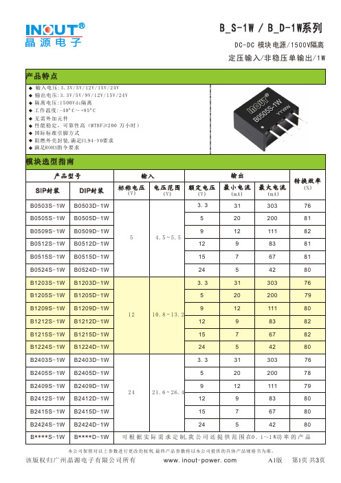
≤ ±1 0% (Typ); ±15%( Max)
1 0 %到1 0 0 %负 载
参照误差包络曲线图
≤7 5 mV p-p ( T y p ) ; 1 0 0 mV p-p ( M a x ) 2 0 M H z带 宽
≤7 5 mV p-p ( T y p ) ; 1 0 0 mV p-p ( M a x ) 2 0 M H z带 宽
过 载 保 护:在通常工作条件下,该产品输出电路对于过载情况无保护功能。最简单的方法是在输入端串接一个自恢复 保险丝,或在电路中外加一个断路器;
输 出 端 外 接 电 容 其 容 值 不 能 过 大,否 则 容 易 造 成模块启动时过流或启动不良,具体应根据容性负载值表进行选择;
对 于 纹 波 噪 声 要 求 较 高 的 场 合 应 外 接L C滤 波 电,如(图1);
一般特性
开关频率
100KHz
1 0 0%负载,输 入标称 电 压
产品工作时外壳升温
1 5℃典型 值
2 5℃ 最大值
温度系数
0 . 0 3 % /℃
1 0 0%满载
引脚耐焊温度
3 0 0℃
焊 点 距外壳1.5mm, 1 0秒
隔离 电压(输入与 输 出)
1500VDC
测 试 时间1分钟,漏 电 流小于1mA
80
B* * * * S- 1W B* * * * D- 1W 可 根 据 实 际 需 求 定 制,我 公 司 还 提 供 范 围 在0 . 1~1 W功 率 的 产 品
本 公 司 保 留 对 以 上 参 数 进 行 更 改 的 权 利,最 终 产 品 参 数 将 以 本 公 司 提 供 的 具 体 产 品 规 格 书 为 准 。
POWERDI5 10A 晶体管直流稳压器商品说明书
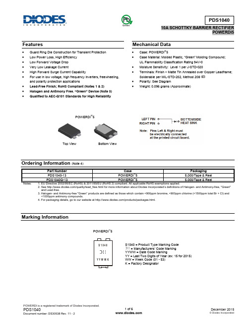
Features∙ Guard Ring Die Construction for Transient Protection ∙ Low Power Loss, High Efficiency ∙ Low Forward Voltage Drop ∙ Very Low Leakage Current∙ High Forward Surge Current Capability∙ For use in low voltage, high frequency inverters, freewheeling, and polarity protection applications∙ Lead-Free Finish; RoHS Compliant (Notes 1 & 2)∙ Halogen and Antimony Free. “Green” Device (Not e 3) ∙ Qualified to AEC-Q101 Standards for High ReliabilityMechanical Data∙ Case: POWERDI ®5∙ Case Material: Molded Plastic, “Green” Molding Compound ; UL Flammability Classification Rating 94V-0 ∙ Moisture Sensitivity: Level 1 per J-STD-020∙ Terminals: Finish – Matte Tin Annealed over Copper Leadframe; Solderable per MIL-STD-202, Method 208 ∙ Polarity: See Diagram∙Weight: 0.096 grams (Approximate)Ordering Information (Note 4)2. See /quality/lead_free.html for more information about Diodes Incorporated’s definitions of Halogen - and Antimony-free, "Green" and Lead-free.3. Halogen- and Antimony-free "Green” products are defined as those which contain <900ppm bromine, <900ppm chlorine (<1500ppm total Br + Cl) and <1000ppm antimony compounds.4. For packaging details, go to our website at /products/packages.html.Marking InformationS1040 = Product Type Marking Code = Manufacturers’ Code Marking YYWW = Date Code MarkingYY = Last Two Digits of Year (ex: 15 for 2015) WW = Week Code (01 - 53) K = Factory DesignatorY Y W W KS 1040Top View Bottom ViewPOWERDI ®5GreenPOWERDI ®5Maximum Ratings(@T A = +25°C, unless otherwise specified.)Single phase, half wave, 60Hz, resistive or inductive load.Thermal CharacteristicsElectrical Characteristics(@T A = +25°C, unless otherwise specified.)Notes: 5. FR-4 PCB, 2oz. Copper, minimum recommended pad layout per .6. Polyimide PCB, 2oz. Copper, minimum recommended pad layout per .7. Polyimide PCB, 2oz. Copper. Cathode pad dimensions 9.4mm x 7.2mm. Anode pad dimensions 2.7mm x 1.6mm.8. Short duration pulse test used to minimize self-heating effect.9. Polyimide PCB, 2oz. Copper. Cathode pad dimensions 18.8mm x 14.4mm. Anode pad dimensions 5.6mm x 3.0mm.10. Devices mounted such that RθJA = 19°C/W.P , P O W E R D I S S I P A T I O N (W )D I , AVERAGE FORWARD CURRENT (A)Fig. 1 Forward Power Dissipation F(AV)I , I N S T A N T A N E O U S F O R W A R D C U R R E N T (A )V , INSTANTANEOUS FORWARD VOLTAGE (V)Fig. 2 Typical Forward Characteristics FV , INSTANTANEOUS REVERSE VOLTAGE (V)Fig. 3 Typical Reverse Characteristics R I , I N S T A N T A N E O U S RE V E R S E C U R R E N T (A )V , INSTANTANEOUS REVERSE VOLTAGE (V)Fig. 4 Typical Reverse Characteristics RC , T O T A L C A P A C I T A N C E (p F )T V , DC REVERSE VOLTAGE (V)Fig. 5 Total Capacitance vs. Reverse Voltage RI , A V E R A G E F O R W A R D C U R R E N T (A )F (A V )T , AMBIENT TEMPERATURE (°C)Fig. 6 Forward Current Derating CurveA2016018020014012010080T , D E R A T E D A M B I E N T T E M P E R A T U R E (°C )A V , DC REVERSE VOLTAGE (V)Fig. 7 Operating Temperature DeratingRPackage Outline DimensionsPlease see AP02002 at /datasheets/ap02002.pdf for the latest version.Suggested Pad Layout Please see AP02001 at /datasheets/ap02001.pdf for the latest version.。
DC电源系列商品说明书
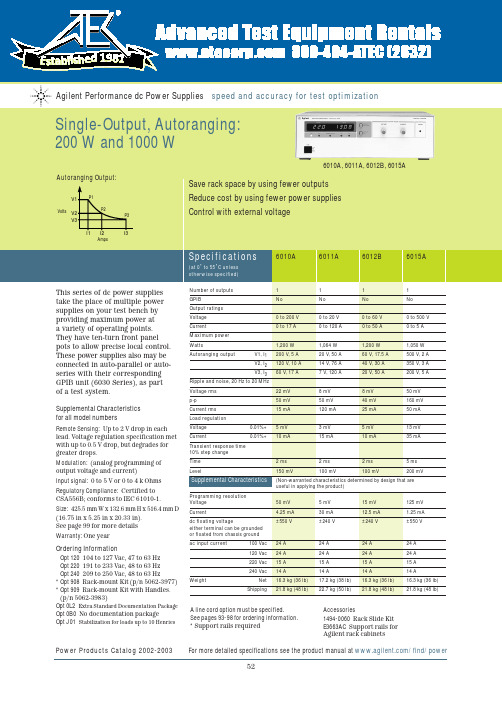
CSA556B; conforms to IEC 61010-1. Size:425.5 mm W x 132.6 mm H x 516.4 mm D (16.75 in x 5.25 in x 20.33 in). See page 99 for more details Warranty:One yearOrdering InformationOpt 120104 to 127 Vac, 47 to 63 Hz Opt 220191 to 233 Vac, 48 to 63 Hz Opt 240209 to 250 Vac, 48 to 63 Hz*Opt 908Rack-mount Kit (p/n 5062-3977)*Opt 909Rack-mount Kit with Handles.(p/n 5062-3983)Opt 0L2Extra Standard Documentation Package Opt 0B0No documentation packageOpt J01Stabilization for loads up to 10 HenriesPower Products Catalog 2002-2003 For more detailed specifications see the product manual at /find/power526010A, 6011A, 6012B, 6015AProgramming resolution Voltage 50 mV 5 mV 15 mV 125 mV Current4.25 mA 30 mA 12.5 mA 1.25 mA dc floating voltage±550 V±240 V±240 V±550 Veither terminal can be grounded or floated from chassis ground ac input current100 Vac 24 A 24 A 24 A 24 A 120 Vac 24 A 24 A 24 A 24 A 220 Vac 15 A 15 A 15 A 15 A 240 Vac14 A 14 A 14 A 14 A WeightNet 16.3 kg (36 lb) 17.2 kg (38 lb) 16.3 kg (36 lb) 16.3 kg (36 lb)Shipping21.8 kg (48 lb)22.7 kg (50 lb)21.8 kg (48 lb)21.8 kg (48 lb)A line cord option must be specified.See pages 93-98 for ordering information.*Support rails requiredAccessories1494-0060Rack Slide Kit E3663AC Support rails for Agilent rack cabinets6030A, 6031A,Power Products Catalog 2002-2003 For more detailed specifications see the product manual at /find/power5354for all model numbersRemote Sensing:Up to 2 V drop in each lead. Voltage regulation specification met with up to 0.5 V drop, but degrades for greater drops.Modulation: (analog programming of output voltage and current)Input signal:0 to 5 V or 0 to 4 k Ohms Size:6030A–32A, 6035A:425.5 mm W x 132.6 mm H x 503.7 mm D (16.75 in x 5.25 in x 19.83 in).6033A, 6038A:212.3 mm W x 177.0 mm H x 516.4 mm D (8.36 in x 6.97 in x 17.87 in).See page 99 for more details.Warranty: Three yearsOrdering InformationOpt 001 Front panel has only line switch, line indicator, and OVP adjust (6030A–33A and 6038A only)Opt 10087 to 106 Vac, 48 to 63 Hz(power supply output is derated to 75%)Opt 120 104 to 127 Vac, 47 to 63 Hz Opt 220191 to 233 Vac, 48 to 63 Hz Opt 240209 to 250 Vac, 48 to 63 Hz Opt 800Rack-mount Kit for Two Half-rack Units Side by Side. Lock link Kit p/n 5061-9694 and 7 in Rack adapter Kit 5063-9215*Opt 908Rack-mount Kit for a Single Half-rack Unit 6033A and 6038A(with blank filler panel); p/n 5062-3960, 6030A–32A and 6035A; p/n 5062-3977*Opt 909 Rack-mount Kit with Handles.For 6030A–32A, 6035A; p/n 5062-3983Power Products Catalog 2002-2003 For more detailed specifications see the product manual at /find/powerProgramming resolution Voltage50 mV 5 mV 15 mV 5 mV 125 mV 1 5 mV Current4.25 mA 30 mA 12.5 mA 7.5 mA 1.25 mA 2.5 mA dc floating voltage±550 V±240 V±240 V±240 V±550 V±240 Veither terminal can be grounded or floated from chassis ground ac input current100 Vac 24 A 24 A 24 A 6 A 24 A 6 A 120 Vac 24 A 24 A 24 A 6.5 A 24 A 6.5 A 220 Vac 15 A 15 A 15 A 3.8 A 15 A 3.8 A 240 Vac14 A 14 A 14 A 3.6 A 14 A 3.6 A WeightNet 16.3 kg 17.2 kg 16.3 kg 9.6 kg 16.3 kg 9.6 kg (36 lb) (38 lb) (36 lb) (21 lb) (36 lb) (21 lb)Shipping21.8 kg 22.7 kg 21.8 kg 11.4 kg 21.8 kg 11.4 kg (48 lb)(50 lb)(48 lb)(25 lb)(48 lb)(25 lb)Opt 0L2 Extra Standard Documentation Package Opt 0B3 Service ManualOpt 0B0 No documentation package Opt J01 Stabilization for loads up to 10 Henries (not available on 6033A)A line cord must be specified for 6030A-32A, 6035A. See pages 93-98 for ordering information.*Support rails required Accessories5080-2148Serial Link Cable, 2 m (6.6 ft)1494-0060Rack Slide KitE3663AC Support rails for Agilent rack cabinetsTo see a copy of the user’s guide, please visit our Web site at/find/manualsBy internet, phone, or fax, get assistance with all your test & measurement needs Online assistance:/find/assistPhone or FaxUnited States:(tel)180****4844Canada:(tel)187****4414(fax) (905) 282-6495China:(tel) 800-810-0189(fax) 1-0800-650-0121Europe:(tel) (31 20) 547 2323(fax) (31 20) 547 2390Japan:(tel) (81) 426 56 7832(fax) (81) 426 56 7840Korea:(tel) (82-2) 2004-5004 (fax) (82-2) 2004-5115Latin America:(tel) (305) 269 7500(fax) (305) 269 7599Taiwan:(tel) 080-004-7866 (fax) (886-2) 2545-6723Other Asia Pacific Countries:(tel) (65) 375-8100 (fax) (65) 836-0252Email:*******************Product specifications and descriptions in this document subject to change without notice.Your Requested Excerpt from the Agilent Power Products CatalogThe preceding page(s) are an excerpt from the 2002-2003 Power Products Catalog .We hope that these pages supply the information that you currently need. If you would like to have further information about the extensive selection of Agilent dc power supplies, ac sources, and dc electronic loads, please visit /find/power to print a copy of the complete Power Products catalog, or to request that a copy be sent to you. You will also find a lot of other useful information on this web site.In the full Power Products Catalog, you will find that Agilent offers much more than basic power generation. If you need basic, clean, power for your lab bench,it’s there. But in each product category, we’ve also integrated the capabilities that you need for a complete power solution, including extensive measurement and analysis capabilities.Please give us a call at your local Agilent Technologies sales office, or call a regional office listed below, for assistance in choosing or using Agilent power products.Keep up to date with Agilent’s Test and Measurement Email UpdatesAs an Email Update subscriber, you will receive periodic customized email updates that match the areas of interest that you have specified. Your update will include products and services, applications and support information, events,and promotions. Sign up today at /find/emailupdates . Check off dc power supplies, ac power sources or electronic loads on your registration form, and we will promptly let you know what’s new in power products! Our Privacy Statement at /go/privacy describes our commitment to you regarding your privacy.Agilent Technologies。
HMBT8050中文资料

HMBT8050中文资料Page No. : 1/3HMBT8050NPN EPITAXIAL TRANSISTORDescriptionThe HMBT8050 is designed for general purpose amplifier applications.FeaturesHigh DC Current hFE=150-400 at IC=150mA ? Complementary to HMBT8550Absolute Maximum RatingsMaximum TemperaturesStorage Temperature........................................................................................... -55 ~ +150 °C Junction Temperature.................................................................................... +150 °C Maximum ? Maximum Power DissipationTotal Power Dissipation (Ta=25°C)............................................................................... 225 mW ? Maximum Voltages and Currents (Ta=25°C)VCBO Collector to Base Voltage......................................................................................... 25 V VCEO Collector to Emitter Voltage...................................................................................... 20 V VEBO Emitter to Base Voltage.............................................................................................. 5 V IC CollectorCurrent (700)mACharacteristics (Ta=25°C)Symbol Min.Typ.Max.Unit Test ConditionsBVCBO 25--V IC=10uA, IE=0BVCEO 20--V IC=1mA, IB=0BVEBO 5--V IE=10uA, IC=0ICBO --1uAVCB=20V. IE=0*VCE(sat)--500mV IC=500mA, IB=50mA VBE(on)--1V VCE=1V, IC=150mA *hFE 150-500VCE=1V, IC=150mA fT 150--MHz VCE=10V, IC=20mA, f=100MHz Cob--10pFVCB=10V, f=1MHz*Pulse Test: Pulse Width ≤380us, Duty Cycle ≤2%Classification Of hFERank D9D D9E Range150-300250-500Page No. : 2/3 Characteristics CurvePage No. : 3/3SOT-23 Dimension*: TypicalInches MillimetersInches MillimetersDIM Min.Max.Min.Max.DIM Min.Max.Min.Max.A 0.11020.1204 2.80 3.04J0.00340.00700.0850.177B 0.04720.0630 1.20 1.60K 0.01280.02660.320.67C 0.03350.05120.89 1.30L0.03350.04530.851.15D 0.01180.01970.300.50S 0.08300.10832.10 2.75G 0.06690.0910 1.70 2.30V0.00980.02560.250.65H0.00050.00400.0130.10Notes: 1.Dimension and tolerance based on our Spec. dated Sep. 07,1997.2.Controlling dimension: millimeters.3.Maximum lead thickness includes lead finish thickness, and minimum lead thickness is the minimum thickness of basematerial.4.If there is any question with packing specification or packing method, please contact your local HSMC sales office.Material:Lead: 42 Alloy; solder platingMold Compound: Epoxy resin family, flammability solid burning class: UL94V-0Important Notice:All rights are reserved. Reproduction in whole or in part is prohibited without the prior written approval of HSMC.? HSMC reserves the right to make changes to its products without notice.HSMC semiconductor products are not warranted to be suitable for use in Life-Support Applications, or systems.HSMC assumes no liability for any consequence of customer product design, infringement of patents, or application assistance.Head Office And Factory:Head Office (Hi-Sincerity Microelectronics Corp.): 10F.,No. 61, Sec. 2, Chung-Shan N. Rd. Taipei Taiwan R.O.C.Tel: 886-2-25212056 Fax: 886-2-25632712, 25368454Factory 1: No. 38, Kuang Fu S. Rd., Fu-Kou Hsin-Chu Industrial Park Hsin-Chu Taiwan. R.O.C Tel: 886-3-5983621~5 Fax: 886-3-5982931。
海尔 PSU505 三通道 DC 电源说明书

Transient Response Time
<50 µs
N
Stability, Constant Output and Temperature ±(% of Output + Offset), 8 hrs
Voltage
<0.2% + 2 mV
Current
<0.1% + 1 mA
Voltage Programming Speed
Voltage
0.01% + 2 mV
Current
0.01% + 300 µA
Load Regulation ±(% of Output + Offset)
Voltage
≤3 mV
≤5 mV
Current
0.01% + 300 µA
Ripple and Noise (20 Hz to 20 MHz)
Weight
6.5 kg (14 lb)
Communications
RS232/USB interface
N-54
)UHHSKRQH _ ,QWHUQDWLRQDO _ )D[ _ 6DOHV#RPHJDFRXN
AVAILABLE FOR FAST DELIVERY!
To Order (Specify Model Number)
Model No.
Price
Description
PSU505
$1990
Linear power supply
EE-2505
125
Reference Book: Electric
Instrument Handbook
DSO5000系列数字存储示波器用户手册(Ver0.9)
激光打标机说明书(内部绝密资料)

激光打标机说明书(内部绝密资料)激光打标机DH-DPSS-50W使用说明书目录激光打标机DH-DPSS-50W (1)目录 (2)一、简介 (4)1. 概述 (4)2. 主要技术指标 (4)二、工作原理及结构 (5)1. 工作原理 (5)2. 结构描述 (5)3. 控制系统机柜中的电源结构说明 (6)三、激光器内部结构及光路调整 (11)1. 激光器内部结构示意: (11)2. 光路调整 (11)四、设备安装要求及操作说明 (12)1.设备安装要求 (12)2. 制冷机的安装 (13)3. 操作流程说明 (14)五、常见故障处理方法 (17)六、使用注意事项 (18)1.光学系统 (18)2.日常维护 (18)3.其它 (19)七、附录 (20)1.二极管功率测试报告 (20)2.各主要接线图 (20)3.维修服务报告 (24)前言本说明书详细介绍了DH-DPSS-50W激光打标机的安装,使用方法及相关维护步骤。
在您打开包装安装并使用本机器以前,请注意以下要项:◆操作者应具备相关的技术培训,或有专人指导;◆本说明书将帮助您了解这部机器并能照章操作;◆本说明书中包含了很多帮您安全、经济、因地制宜进行操作的重要提示。
如果您能遵循这些提示,不仅可以避免危险事故,降低维修费用,减少停机检修时间,还可以提高机器的可信度和工作寿命;◆本说明书中包括工伤预防和环境保护等事宜,用户可以根据本国的具体情况补充进去;◆说明书应存放在机器旁以供随时查阅;◆建议每一位与本机器有关的工作人员都要阅读这本说明书,例如:◆操作人员:包括装配、排除日常工作故障、清除工作垃圾、保养机器和处理废料的人员;◆维修保养:包括保养、检修、维修人员;一、简介1. 概述DH-DPSS-50W型激光打标机是一种集光、机、电为一体的专业激光打标设备,是由本公司生产,关键部件采用进口元器件,具有外观新颖,结构独特,操作简便,调制频率高,打标速度快,精度高,性能稳定等优点,可广泛用于各类金属和非金属表面做永久性标记。
DC DC模块电源IB05_S-W75R3系列商品说明书
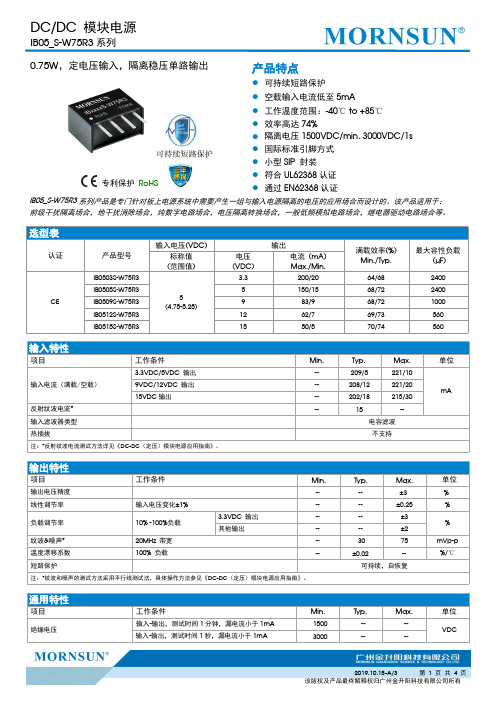
选型表认证产品型号输入电压(VDC)输出满载效率(%)Min./Typ.最大容性负载(µF)标称值(范围值)电压(VDC)电流(mA)Max./Min.CEIB0503S-W75R35(4.75-5.25)3.3200/2064/682400IB0505S-W75R35150/1568/722400IB0509S-W75R3983/968/721000IB0512S-W75R31262/769/73560IB0515S-W75R31550/570/74560输入特性项目工作条件Min.Typ.Max.单位输入电流(满载/空载)3.3VDC/5VDC 输出--209/5221/10mA9VDC/12VDC 输出--208/12221/2015VDC 输出--202/18215/30反射纹波电流*--15--输入滤波器类型电容滤波热插拔不支持注:*反射纹波电流测试方法详见《DC-DC (定压)模块电源应用指南》。
输出特性项目工作条件Min.Typ.Max.单位输出电压精度----±3%线性调节率输入电压变化±1%----±0.25%负载调节率10%-100%负载 3.3VDC 输出----±3%其他输出----±2纹波&噪声*20MHz 带宽--3075mVp-p 温度漂移系数100%负载--±0.02--%/℃短路保护可持续,自恢复注:*纹波和噪声的测试方法采用平行线测试法,具体操作方法参见《DC-DC (定压)模块电源应用指南》。
通用特性项目工作条件Min.Typ.Max.单位绝缘电压输入-输出,测试时间1分钟,漏电流小于1mA 1500----VDC输入-输出,测试时间1秒,漏电流小于1mA3000----0.75W ,定电压输入,隔离稳压单路输出专利保护RoHS产品特点●可持续短路保护●空载输入电流低至5mA ●工作温度范围:-40℃to +85℃●效率高达74%●隔离电压1500VDC/min,3000VDC/1s ●国际标准引脚方式●小型SIP 封装●符合UL62368认证●通过EN62368认证IB05_S-W75R3系列产品是专门针对板上电源系统中需要产生一组与输入电源隔离的电压的应用场合而设计的。
产品型号
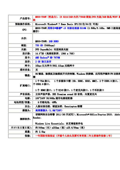
联想U410-IFI处理器第三代智能英特尔® 酷睿™ i5 处理器i5-3317U操作系统正版Windows® 7 家庭普通版 64位推荐升级至正版Windows® 7 专业版内存4GB DDR3硬盘500G大容量高速硬盘+24G固态硬盘显示屏14.0" WXGA超薄炫彩屏,16:9黄金比例显卡NVIDIA Geforce G610M 高性能独立显卡,全面支持DX11 显示内存1G显存键盘联想高触感巧克力键盘视频输出HDMI 1.4高清影音端口摄像头100万像素HD高清摄像头,支持安全易用的人脸识别功能声音系统Dolby Home Theatre音效认证+抗噪麦克风蓝牙蓝牙3.0模块标准接口HDMI 1.4接口,2个USB 3.0接口(读写速度超过USB 2.0 10倍),2个USB 2.0接口,RJ45以太网口,全阵列式抗噪麦克风,支持立体音的耳机/音频输出整合插孔,多功能读卡器电源100~240V宽电压电源适配器电池类型高性能聚合物电池,9小时超长续航时间尺寸344x235x21mm重量1.85kg(含有聚合物电池,具体重量依据产品出货配置为准) 可选件笔记本包鼠套装礼包(需另行购买)特色功能精湛工艺:极致一体化设计,外表看不到任何一颗螺丝全铝合金外观,20多道冲压、CNC、钻石洗工艺,纳米级喷砂着色工艺超长待机:9小时超长续航,3个月深度睡眠待机即开即用:支持1秒瞬间唤醒,7秒快速从深度睡眠唤醒系统加速:数据存取速度提升至最高4倍,加快运行速度多点触控Touchpad,打字时防误触配备第四代Dolby Home Theatre音效认证*一键拯救系统华硕A55VDLenovo/联想 Z480A-IFI处理器第三代智能英特尔® 酷睿™i5处理器i5-3210M(2.5GHz,可睿频加速至3.1GHz)操作系统Linpus Lite(如需安装WIN7系统,请联系客服)内存4GB DDR3 1333MHz高速内存(支持扩展至8GB)硬盘500G SATA 硬盘无线局域网卡802.11bgn无线局域网卡光驱超级DVD刻录光驱显示屏14.0" WXGA LED背光屏,16:9黄金比例显卡NVIDIA Geforce GT630M 高性能独立显显示内存1G DDR3大容量高速独立显存键盘联想高触感巧克力键盘视频输出HDMI 高清影音端口,标准VGA声音系统第四代Dolby 家庭影院环绕立体音效+2W×2专业级超大音响+抗噪麦克风网络连接10M/100M以太自适应网卡标准接口HDMI 接口,2个USB2.0接口,2个USB3.0接口,VGA接口,RJ45,全阵列式抗噪麦克风,支持立体音的耳机插孔/音频输出,多合一读卡器(SD/MMC/MS/MS pro/XD)电源100~240V宽电压电源适配器电池类型高性能6芯锂离子电池尺寸341mm x 232mm x 20~32.4mm重量 2.3Kg(含有6芯电池,具体重量依据产品特色功能高性能娱乐显卡,支持3D电视输出第四代Dolby 家庭影院环绕立体音效专业级、高保真、超拉风超大音响一键影音快捷触控专区潮流多彩外观、3D立体晶钻工艺超静音高效散热设计电池寿命延长技术+高级电源管理*一键拯救系统Dell/戴尔 Ins14r-9518 戴尔笔记本 14r-9518os。
巨能伟业开关电源规格书

注: 保护闭锁,电路恢复后,市电断电≥2S,重新上电,电源恢复正常工作。
4 其它特性
序号
项目
技术要求
4.1 MTBF
≥40,000
4.2 漏电流
<1.0mA(Vin=220Vac)
VAC 测试条件:满载
VAC
A
HI-CUP 打嗝自恢
复,避免了电源长
A
期短路后损坏电
源。
VDC
单
备注
位
H
GB8898-2001 9.1.1 项测试方法
六、安规特性
第4页共7页
深圳市巨能伟业技术有限公司
序号
项目
抗电 输 入 对 1
强度 输出
抗电 输 入 对
2
强度 地
抗电 输 出 对 3
强度 地
测试条件
产品名称:N200V5-A 版本号: V1.1 日期: 2012/3/31
备注
2000Vac/10mA/1min
一般要求 GB/T 2423.22-2002 电工电子产品环境试验,第 2 部分:试验 N:温度变化 GB/T 14508-93 等级公路货物运输机械环境条件 EN55022:1998 信息技术设备—无线干扰特性—限值和测量方法; EN55024:1998 信息技术设备—抗干扰特性—限值和测量方法; CEI IEC 61000-4-2 2001 电磁兼容 试验和测量技术 静电放电抗扰度试验 CEI IEC 61000-4-3 2002 电磁兼容 试验和测量技术 射频电磁场辐射扰抗扰度试验 CEI IEC 61000-4-4 1998 电磁兼容 试验和测量技术 电快速瞬变脉冲群抗扰度试验 CEI IEC 61000-4-5 1999 电磁兼容 试验和测量技术 浪涌(冲击)抗扰度试验 CEI IEC 61000-4-6 2001 电磁兼容 试验和测量技术 射频场感应的传导骚扰抗扰度 CEI IEC 61000-4-8 1993 电磁兼容 试验和测量技术 工频磁场抗扰度试验 CEI IEC 61000-4-11 1994 电磁兼容 试验和测量技术 电压暂降、短时中断和电压变化的抗扰度
开关电源 PTH05010W中文手册

5V输入,0.8~3.6V输出具有上电追踪功能,能够设置各个电源模块的上电顺序。
具有开关抑制、输出电压校准和容量上/下控制。
输出电压检测1 GND:地2 Vin:正电压输入,用470uF胆电容对地。
3 Inhibit:集电极开路或漏极开路地参考负逻辑输入。
低电平禁止调制输出,关断输出电压。
当有效时,有调节器拉动的输入电流大大减少。
如果该引脚不连接,则在有有效电源输入时该电源模块产生输出。
4 V o Adjust:该引脚与7引脚间直接连接一个0.1W(1%)电阻来设置高于0.8V的输出电压。
电阻的温度稳定度为100ppm/摄氏度或更好。
电阻值与输出电压的关系为:Rset=[10K×0.8V/(Vout-0.8V)]-2.49K。
如果不连接,则模块输出电压为默认的最低值。
5 Vo Sense:该输入可以使调节电路补偿电源模块与负载之间的电压降。
为了得到最好的电压精度,该引脚应该接在V out引脚上。
6 V out:校准后电源输出。
330uF胆电容改善瞬态负载响应。
7 GND:地8 Track:模拟控制数引脚,使输出电压跟随外部电压。
该引脚在模块上电20ms后有效,允许直接控制输出电压从0V到设置点的电压。
在该范围内,输出将跟随Track引脚上的电压。
当控制电压高于电压范围后,模块在该设置点电压上调节。
该功能能够使输出电压与其他在同一个输入总线上的模块同步上升。
如果不使用,该引脚接Vin。
模块的输出不能跟随自己的输入电压。
9 Margin Down:该引脚接地后,输出电压将比平时低5%。
10 Margin Up:当该引脚连接到地时,输出电压增加5%。
输入要求集电极开路或漏极开路接口。
不与TTL兼容。
PTH05010与PTH03010系列电源模块的电容使用:输入电容:输入电容470uF胆电容;可使用瓷片电容来改善输入总线上的波纹。
输出电容:(可选)对于负载瞬态变化的设备,外部暑促电容可以改善输出响应,一般接330uF胆电容电容。
Walsin_RF15N0R7B500CT规格书

2. FEATURES
50V ≦2.5% ≦5% 1210≧4.7µF
≦ 10%
0402≧0.1µF ;0603≧1µF;0805≧1µF;1206≧2.2µF; 1210≧10µF;TT series
35V ≦3.5% ≦10% 0603≧1µF;0805≥2.2µF; 1210≧10µF
≦5% 0201≧0.01µF;0805≧1µF; 1210≧10µF
1. DESCRIPTION
MLCC consists of a conducting material and electrodes. To manufacture a chip-type SMT and achieve miniaturization, high density and high efficiency, ceramic condensers are used.
Packaging style T=7” reeled R=7” reeled (2mm pitch for 0603 size; paper tape) G=13” reeled
5. EXTERNAL DIMENSIONS
Size Inch (mm) 0402 (1005)
0603 (1608)
L (mm)
1.00±0.05
1.60±0.10 1.60
+0.15/-0.10
W (mm)
SN75107BD 数据手册说明书
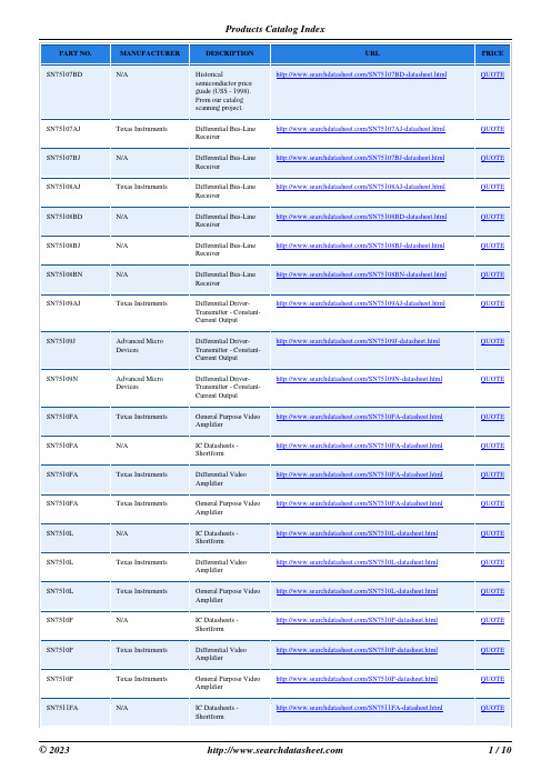
SN75107AJ SN75107BJ SN75108AJ SN75108BD SN75108BJ SN75108BN SN75109AJ
SN75109J
SN75109N
SN7510FA SN7510FA SN7510FA SN7510FA SN7510L SN7510L SN7510L SN7510P SN7510P SN7510P SN7511FA
N/A
IC Datasheets -
/SN7510L-datasheet.html
Shortform
Texas Instruments
Differential Video Amplifier
/SN7510L-datasheet.html
Advanced Micro Devices
Differential DriverTransmitter - ConstantCurrent Output
/SN75109N-datasheet.html
Texas Instruments
General Purpose Video Amplifier
Shortform
Texas Instruments
Differential Video Amplifier
/SN7510P-datasheet.html
Texas Instruments
General Purpose Video Amplifier
Differential Video Amplifier
/SN7510FA-datasheet.html
Texas Instruments
General Purpose Video Amplifier
DCH中文资料

B4-31DCH SERIES3 WATTF EATURES•–55°C to 100°C •4 to 6.5,9 to 15,or 20 to 32 VDC input •Fully isolated•Output regulated from input side•100 kHz typical switching frequency •Topology –Push-Pull DC/DC Converter •Up to 75% efficiency •No minimum load•Output capacitor suggestedDESCRIPTIONThe DCH Series™offers isolated, unregulated DC/DC converters with up to 3 watts of output power in a low profile (0.350 max.) metal package. Single and dual output models are available with input voltages of 5, 12, or 28 VDC. DCH Series converters operate over a –55°C to +100°C temperature range.DCH Series converters use a non-saturating core circuit operating at a frequency of approximately 100 kHz, which reduces reflectedinput ripple and minimizes EMI/RFI problems. For applications requiring MIL-STD-461C, CEO3, reflected input ripple levels, refer to Section B5 or contact your Interpoint representative for matchingEMI filters.Figure 1 shows a standard connection scheme for a dual output model. Users may also elect to use a dual output device to providea single output at double the rated output voltage. The double voltage connection is achieved by leaving the normal output common pin (Pin 15) unconnected and using either the positive ornegative Vout pin for the output common connection.On all DCH Series models, a tantalum capacitor with a minimum value of 22 µF and an appropriate voltage rating should be connected between the output common and the output line(s) tominimize output ripple.DC/DC C ONVERTERS 5,12,OR 28 V OLT INPUTOutput Current vs Output VoltageDCH2805S F IGURE 3Efficiency DCH2805S F IGURE 2Efficiency DCH1215D F IGURE 4Output Current vs Output VoltageDCH1215D F IGURE 5Size (max.): 0.975 x 0.800 x 0.350 inches (24.77 x 20.32 x 8.89 mm)See section B8, case A3, for dimensions.Weight:20 grams typicalScreening:Standard or ES. See Section C2 for screening options,see Section A5 for ordering information.F IGURE 1:D UAL DCH C ONVERTER WITHE XTERNAL C APACITORSTypical Performance Curves:25°C Tc ,nominal VinTYPICAL CHARACTERISTICRECOMMENDED OPERATING CONDITIONABSOLUTE MAXIMUM RATINGB4-32DCH SERIES 3 WATTDC/DC C ONVERTERSOutput Voltage Tolerance (Full Load)• 5 volt output models ±0.25•12 volt output models ±0.4•15 volt output models ±0.5•28 volt output models ±0.6 Line Regulation•Output is directly proportional to input voltage.Output Voltage Temperature Coefficient •0.02%/°C maximum Converter Frequency •100 kHz typical Isolation•100 megohm minimum at 500 VOutput Power • 3 wattsLead Soldering Temperature (10 sec per lead)•300°CStorage Temperature Range (Case)•–55°C to +125°CInput Voltage Range (VDC)• 5 volt input models 4.0 to 6.5 •12 volt input models 9.0 to 15.0•28 volt input models 20.0 to 32.0Case Operating Temperature (Tc)•–55°C to +100°C full powerElectrical Characteristics:25°C Tc,28 VDC Vin,100% load,unless otherwise specified.24600-001-DTS Rev A DQ# 1024All technical information is believed to be accurate, but no responsibility is assumed for errors or omissions. Interpoint reserves the right to make changes in products or specifications without notice. DCH Series is a trademark of Interpoint.Copyright ©1991 - 1999 Interpoint. All rights reserved.B8-6CASE AC ASESNote: Although every effort has been made to render the case drawings at actual size, variations in the printing process may cause some distortion. Please refer to the numerical dimensions for accuracy.C2-12QA SCREENING 85°C PRODUCTSTEST (85°C Products excluding HR products)STANDARD/ESPRE-CAP INSPECTION Method 2017yesyesTEMPERATURE CYCLE (10 times)Method 1010, Cond. B, -55°C to 125°C noyesCONSTANT ACCELERATION Method 2001, 500 g noyesBURN-IN96 hours at 70°C ambient (typical)noyesFINAL ELECTRICAL TEST MIL-PRF-38534, Group A Subgroups 1 and 4: +25°C case yesyesHERMETICITY TESTINGFine Leak, Method 1014, Cond. A no yes Gross Leak, Method 1014, Cond. C no yes Gross Leak, Dip (1 x 10⁻³)yesnoFINAL VISUAL INSPECTION Method 2009yesyesTest methods are referenced to MIL-STD-883 as determined by MIL-PRF-38534.MFW Series MTW SeriesMHE/MLP Series MHL Series MRH Series MTO Series MSR Series DCH SeriesFM/FMA/FMB EMI Filters MSF EMI Filter85°C P RODUCTSApplies to the following products:。
HT1050中文资料

HT10XXVoltage RegulatorPin AssignmentApplications•Battery-powered equipment •Communication equipment•Audio/Video equipmentGeneral DescriptionThe HT10XX series is a set of three-terminal low power voltage regulators implemented in CMOS technology . They are available with several fixed output voltages ranging from 1.5V~7.0V . The ad-vantage of CMOS technology is low voltage drop-out and low quiescent current.Although designed primarily as fixed voltage regulators, these devices can be used with ex-ternal components to obtain variable voltagesand currents.Features•Low power consumption •Low voltage dropout•Low temperature coefficient•Wide operating voltage (12V Max.)•TO-92 & SOT-89 packages13rd Oct ’96Pad Assignment Unit:milChip size: 76 × 50 (mil)2*The IC substrate should be connected to VDD in the PCB layout artwork.Block DiagramAbsolute Maximum RatingsSupply Voltage...............................–0.3V to 13V Storage Temperature.................–50°C to 125°C Power Dissipation...................................250mW Operating Temperature...................0°C to 70°C23rd Oct ’96Selection GuideElectrical CharacteristicsHT10XX series (HT1015, HT1016, +1.5V output type)(Ta=25°C)33rd Oct ’96HT10XX series (HT1033, HT1034, +3.3V output type)(Ta=25°C)43rd Oct ’96HT10XX series (HT1044, HT1045, +4.4V output type)(Ta=25°C)53rd Oct ’96HT10XX series (HT1070, HT1071, +7.0V output type)(Ta=25°C)63rd Oct ’96Application CircuitThe basic circuits using the HT10XX seriesHigh output current positive voltage regulatorShort-Circuit protection for Tr1Circuit for increasing output voltageV OUT= V XX(1+R2R1)+ I SS R2≈ V XX(1 +R2 R1)Circuit for increasing output voltageV OUT= V XX+ V DIConstant current regulatorI OUT=V XXR A+ I SSDual supplyHT10XX93rd Oct ’96Package InformationTO-92HT10XX103rd Oct ’96SOT–89 outlineφTaped parts quantity1000 Pcs/1 reel (–0/+10PCS) Mechanical data。
MORNSUN B05_XT-2WR3 Series DC DC Converter Datashe

2W isolated DC-DC converterFixed input voltage,unregulated single outputPatent Protection RoHSFEATURES●Continuous short-circuit protection ●No-load input current as low as 8mA●Operating ambient temperature range:-40℃to+105℃●High efficiency up to 86%●Compact SMD package●I/O isolation test voltage 1.5k VDC●Industry standard pin-outB05_XT-2WR3series are designed for use in distributed power supply systems and especially suitable in applications such as pure digital circuits,low frequency analog circuits,relay-driven circuits and data switching circuits.Selection GuideCertificationPart No.Input Voltage (VDC)OutputFull Load Efficiency (%)Min./Typ.Capacitive Load(µF)Max.Nominal (Range)Voltage (VDC)Current(mA)Max./Min.--B0503XT-2WR35(4.5-5.5) 3.3400/4074/782400B0505XT-2WR35400/4080/842400B05X7XT-2WR37286/2980/841000B0509XT-2WR39222/2281/851000B0512XT-2WR312167/1781/85560B0515XT-2WR315133/1382/86560B0524XT-2WR32483/882/86220Input SpecificationsItemOperating ConditionsMin.Typ.Max.UnitInput Current(full load /no-load)5VDC input3.3VDC output--339/8357/--mA5VDC/7VDC output --477/8500/--9VDC/12VDC output --471/8494/--15VDC/24VDC output--466/8488/--Reflected Ripple Current*--15--Surge Voltage (1sec.max.)-0.7--9VDCInput Filter Capacitance filter Hot PlugUnavailableNote:*Reflected ripple current testing method please refer to DC-DC Converter Application Note for specific operation.Output SpecificationsItemOperating ConditionsMin.Typ.Max.UnitVoltage AccuracySee output regulation curve (Fig.1)Linear RegulationInput voltage change:±1%3.3VDC output----±1.5--5VDC/7VDC/9VDC/12V DC/15VDC/24VDC output ----±1.2Load Regulation10%-100%load3.3VDC output --1020%5VDC/7VDC output--9159VDC output--81012VDC/15VDC output --71024VDC output--610Ripple &Noise*20MHz bandwidth --75200mVp-p Temperature Coefficient Full load--±0.02--%/℃Short-circuit ProtectionContinuous,self-recoveryNote:*The“parallel cable”method is used for ripple and noise test,please refer to DC-DC Converter Application Notes for specific information. General SpecificationsItem Operating Conditions Min.Typ.Max.UnitIsolation Input-output electric strength test for1minute with aleakage current of1mA max.1500----VDC Insulation Resistance Input-output resistance at500VDC1000----MΩIsolation Capacitance Input-output capacitance at100kHz/0.1V--20--pFOperating Temperature Derating when operating temperature≥85℃,(seeFig.2)-40--105℃Storage Temperature-55--125Case Temperature Rise Ta=25℃--25--Storage Humidity Non-condensing5--95%RHReflow Soldering Temperature*Peak temp.Tc≤245℃,maximum durationtime≤60s over217℃Vibration10-150Hz,5G,0.75mm.along X,Y and Z Switching Frequency Full load,nominal input voltage--220--kHz MTBF MIL-HDBK-217F@25℃3500----k hours Moisture Sensitivity Level(MSL)IPC/JEDEC J-STD-020D.1Level1Note:*See also IPC/JEDEC J-STD-020D.1.Mechanical SpecificationsCase Material Black plastic;flame-retardant and heat-resistant(UL94V-0)Dimensions13.20x11.40x7.25mmWeight 1.4g(Typ.)Cooling Method Free air convectionElectromagnetic Compatibility(EMC)Emissions CE CISPR32/EN55032CLASS B(see Fig.4for recommended circuit) RE CISPR32/EN55032CLASS B(see Fig.4for recommended circuit)Immunity ESD IEC/EN61000-4-2Air±8kV,Contact±6kV perf.Criteria B Typical Characteristic Curves3.3VDC output5VDC/7VDC/9VDC/12VDC/15VDC/24VDC outputFig.1Design Reference1.Typical applicationInput and/or output ripple can be further reduced,by connecting a filter capacitor from the input and/or output terminals to ground as shown in Fig.3.Choosing suitable filter capacitor values is very important for a smooth operation of the modules,particularly to avoid start-up problems caused by capacitor values that are too high.For recommended input and output capacitor values refer to Table 1.Vin0VDCCinDC CoutFig.3Table 1:Recommended input and output capacitor valuesVin Cin Vo Cout5VDC 4.7µF/16V3.3VDC/5VDC 10µF/16V ----7VDC/9VDC4.7µF/16V ----12VDC 2.2µF/25V ----15VDC 1µF/25V ----24VDC0.47µF/50V2.EMC compliance circuitFig.4EmissionsC1,C24.7µF /16VC3Refer to the Cout in Fig.3CY 270pF/2kV LDM6.8µH3.For additional information,please refer to DC-DC converter application notes on80O u t p u t P o w e r P e r c e n t (%)Ambient Temp.()℃Temperature Derating CurveSafe Operating AreaFig.2Dimensions and Recommended Layout Tape and Reel InfoNotes:1.For additional information on Product Packaging please refer to .Tube Packaging bag number:58210024,RollPackaging bag number:58200054;2.If the product is not operated within the required load range,the product performance cannot be guaranteed to comply with allparameters in the datasheet;3.The maximum capacitive load offered were tested at input voltage range and full load;4.Unless otherwise specified,parameters in this datasheet were measured under the conditions of Ta=25℃,humidity<75%RH with nominalinput voltage and rated output load;5.All index testing methods in this datasheet are based on our company corporate standards;6.We can provide product customization service,please contact our technicians directly for specific information;7.Products are related to laws and regulations:see"Features"and"EMC";8.Our products shall be classified according to ISO14001and related environmental laws and regulations,and shall be handled byqualified units.MORNSUN Guangzhou Science&Technology Co.,Ltd.Address:No.5,Kehui St.1,Kehui Development Center,Science Ave.,Guangzhou Science City,Huangpu District,Guangzhou,P.R.China Tel:86-20-38601850Fax:86-20-38601272E-mail:***************。
3位串并转换led驱动芯片
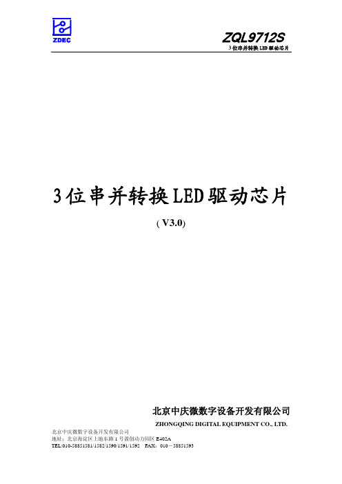
管脚描述 电源地
串行数据输入 加载信号输入 输出使能输入 串行时钟输入
驱动输出 电源地 驱动输出 驱动输出 串行时钟输出 输出使能输出 加载信号输出 串行数据输出 电源输入
北京中庆微数字设备开发有限公司
4
地址:北京海淀区上地东路 1 号盈创动力园区 E402A
TEL:010-58851581/1582/1590/1591/1592 FAX:010-58851593
2
逻辑框图
ZQL9712S
图 1 功能模块
北京中庆微数字设备开发有限公司
1
地址:北京海淀区上地东路 1 号盈创动力园区 E402A
TEL:010-58851581/1582/1590/1591/1592 FAX:010-58851593
性能参数
图 2 信号时序
ZQL9712S
最大工作范围
参数 供电电压 输入电压 输出电流 输出电压 时钟频率
+0.1
+0.1
+0.1
单位
ns ns ns ns ns ns uA
时序参数
参数 时钟高电平宽度 时钟低电平宽度 信号建立时间 信号保持时间
符号 CLKH CLKL SETUP HOLD
测试条件
最小 25 25 10 10
典型
最大
单位 ns ns ns ns
参数
符号
VDD
T=25。C
T=-40~85。C T=-55~125。C 单位
− VBE
BO
式中,VOH 为驱动输出端输出高电平电压值,VBE 为三极管饱和导通管时发射结电压,IBO 为三
极管饱和导通基极电流。
在 ZQL9712S 多 LED 应用电路中,三极管集电极电阻 RR2、RG2、RB2 阻值计算方法如下:
- 1、下载文档前请自行甄别文档内容的完整性,平台不提供额外的编辑、内容补充、找答案等附加服务。
- 2、"仅部分预览"的文档,不可在线预览部分如存在完整性等问题,可反馈申请退款(可完整预览的文档不适用该条件!)。
- 3、如文档侵犯您的权益,请联系客服反馈,我们会尽快为您处理(人工客服工作时间:9:00-18:30)。
Part Numbering Scheme
PRODUCT LINE DCH
H = 3kV, unregulated output
POWER 01
01 = 1W
INPUT VOLTAGE
05
05 = 5V
OUTPUT VOLTAGE
05 05 = 5V 12 =12V 15 = 15V
SINGLE/DUAL S
SBVS073C – MAY 2006 – REVISED AUGUST 2006
MIN
TYP
MAX UNIT
1
W
–10
10
%
3
kVDC
3.5
kVDC
1
%
70
kHz
Single Output
18
Dual Output
22
FITS
–40
+85
°C
ELECTRICAL CHARACTERISTICS PER DEVICE
元器件交易网
DCH01 Series
SBVS073C – MAY 2006 – REVISED AUGUST 2006
MINIATURE, 1W, 3kV ISOLATED UNREGULATED DC/DC CONVERTERS
FEATURES
• Up To 78% Efficiency • 3kVDC Isolation • UL60950 Certified Product (pending) • Industry Standard Footprint • JEDEC SIP-7 Package
INPUT VOLTAGE (V)
5 ± 10% 5 ± 10% 5 ± 10% 5 ± 10% 5 ± 10% 5 ± 10%
OUTPUT VOLTAGE
(V)
5
12
15 ±5 ±12 ±15
DCH01 Products
OUTPUT CURR ±100 ±42 ±33
OUTPUT POWER (W) 1 1 1 1 1 1
ISOLATION VOLTAGE
(kVDC) 3 3 3 3 3 3
PACKAGE-LEAD SIP-7 SIP-7 SIP-7 SIP-7 SIP-7 SIP-7
ABSOLUTE MAXIMUM RATINGS
over operating free-air temperature range (unless otherwise noted) (1)
S = Single D = Dual
PACKAGE N
N = SIP Thru-hole
PIN CONFIG
7
7 = SIP-7
TRANSPORT MEDIA
Blank = Tray T = Tape & Reel
MODEL DCH010505S DCH010512S DCH010515S DCH010505D DCH010512D DCH010515D
NO LOAD INPUT
CURRENT (mA) IQ
0% LOAD TYP 60 60 65 65 65 65
EFFICIENCY (%)
BARRIER CAPACITANCE
(pF)
CISO
100% LOAD(2) TYP 72 72 74 75 75 76
TYP 3 3 4 4 3 3
(1) 20MHz bandwidth.
RELIABILITY
TEST CONDITIONS
Calculated
Per Telcordia SR-332; 50% stress; TA = +40°C
TEMPERATURE RANGE Operating (1) During UL60950 recognition tests only.
ORDERING INFORMATION
For the most current package and ordering information, see the Package Option Addendum at the end of this data sheet, or see the TI website at .
ESD damage can range from subtle performance degradation to complete device failure. Precision integrated circuits may be more susceptible to damage because very small parametric changes could cause the device not to meet its published specifications.
The DCH01 series is a family of miniature, 1W, 3kV isolated DC/DC converters. Featured in an industry standard SIP-7 footprint, the DCH01 series requires minimal external components, reducing board space. The DCH01 series provides both single and dual split-supply outputs.
DCH01 Series
SBVS073C – MAY 2006 – REVISED AUGUST 2006
EDJ PACKAGE SIP-7 (Single)
(Top View)
DEVICE INFORMATION
DCH01
EDJ PACKAGE SIP-7 (Dual) (Top View)
(2) 100% load current = 1W/VNOM typ. (3) Load Regulation = (VO at 10% load - VO at 100% load) / VO at 100% load.
Submit Documentation Feedback
3
元器件交易网
2
Submit Documentation Feedback
元器件交易网
DCH01 Series
ELECTRICAL CHARACTERISTICS
At TA = +25°C, VI = 5V unless otherwise noted.
PARAMETER
All trademarks are the property of their respective owners.
PRODUCTION DATA information is current as of publication date. Products conform to specifications per the terms of the Texas Instruments standard warranty. Production processing does not necessarily include testing of all parameters.
The use of a highly integrated package design results in highly reliable products with high power densities. High performance and small size makes the DCH01 suitable for a wide range of applications including signal chain applications and ground loop elimination.
APPLICATIONS
• Point-of-Use Power Conversion • Ground Loop Elimination • Data Acquisition • Industrial Control and Instrumentation • Test Equipment
DESCRIPTION
Input Voltage Storage temperature range
5V input models
DCH01 SERIES 7
–40 to +125
UNIT V °C
(1) Stresses beyond those listed under Absolute Maximum Ratings may cause permanent damage to the device. These are stress ratings only, and functional operation of the device at these or any other conditions beyond those indicated is not implied. Exposure to absolute maximum rated conditions for extended periods may affect device reliability.
Single Output Block Diagram
+VI
+VO
Power
-VI
Controller
-VO
Dual Output Block Diagram
+VI
Power
-VI
Controller
+VO COM -VO
Please be aware that an important notice concerning availability, standard warranty, and use in critical applications of Texas Instruments semiconductor products and disclaimers thereto appears at the end of this data sheet.
