X93255UV14I中文资料
MSI Cubi 5 12M商品说明说明书
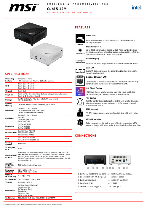
© 2023 Micro-Star Int'l Co.Ltd. MSI is a registered trademark of Micro-Star Int'l Co.Ltd. All rights reserved.SPECIFICATIONSOperating System Windows 11 Home- MSI recommends Windows 11 Pro for business CPU Intel ® Core ™ i7-1255UIntel ® Core ™i5-1235UIntel ® Core ™i3-1215U Chipset Intel ®SoCGraphics Intel ®Iris ®Xe Graphics (Core i5 above with dual-channel memory)Intel ® UHD Graphics (Core i3)Storage 1x M.2 SSD (NVMe PCIe Gen4 x4 / SATA auto switch)1x 2.5" HDD / SSDSystem Memory 2x DDR4 2666/ 3200MHz SO-DIMMs, up to 64GB I/O (Front)2x USB 3.2 Gen 2 Type A1x Thunderbolt 4 (USB Type C port)1x Mic-in/ Headphone-out combo I/O (Rear)2x USB 3.2 Gen 2 Type A 2x RJ451x HDMI™-out (2.0b)1x DP-out (1.4)Bluetooth4.2 (for AC 3168)5.2 (for AX201)5.3 (for AX211)Wireless LAN Intel Wireless AC 3168Intel Wireless AX201Intel Wireless AX211LAN 1x Realtek ®RTL8111H1x Realtek ®RTL8125BG-CG Cooling System Fan Cooler AC Adapter /PSU65WMANAGEMENTUTILITYMSI Center: Hardware Monitoring, Free Up Memory, Clean Up Disk,LAN Manager, MSI Recovery, F3 Recovery, Devices Speed Up, SmartPriority, Smart Image Finder, Noise Cancellation, Live Update,Microsoft App Update, System Info, Troubleshooting, Contact Us, MSI Forum & Channel SECURITY UTILITY &DEVICE MSI Center: System Diagnosis Dimension (WxDxH)124 x 124 x 53.7 mm (4.88 x 4.88 x 2.11 inch)WEIGHT(N.W./ G.W.)0.55 kg / 1.4 kgVESA Mount 100 x 100 mm / 75 x 75 mm Volume0.66 Liter / 1.39 pt Accessories1x User Manual (Optional)1x Quick Guide 1x Warranty Card 1x Adpator 1x Power CordVESA Mount ScrewsCertificatesFCC, CB/CE, UL & CUL, VCCI, RCM, ENERGY STARDual LAN design provides the second LAN backup and a safer network environment 2.5Gbps Ethernet LANConnect and rapidly transfer data over a network with the high-bandwidth and low-latency 2.5Gbps Ethernet LAN.MSI Cloud CenterMSI Cloud Center app brings you a private cloud and helps backup files of your mobile devices (Android & iOS)MSI CenterThe MSI Center takes optimization to the next level with easily adjustable system modes and resources for a wide range of scenarios and needs.TPM SupportFW TPM design secures your confidential data with encryption keys.VESA MountableTo be mounted on the wall of your office & home with a VESAstandard design which can make it completely invisible on a desk.CONNECTIONS1. 1x Mic-in/ Headphone-out combo 3. 1x Thunderbolt 4 (USB Type C)5. 1x Kensington Lock 7. 1x DP out (1.4)9. 2x USB 3.2 Gen 2 Type A2. 2x USB3.2 Gen 2 Type A4. 1x Power botton 6. 1x HDMI™ out (2.0b)8. 2x RJ4510. 1x DC JackNote *Upgrade timing may vary by device. Features and app availabilitymay vary by region. Certain features require specific hardware (seehttps:///en-us/windows/windows-11-specifications).Generated223-11-9,checkforthelatestversionwww.msi.com/datasheet.Theinformationprovidedinthisdocumentisintendedforinformationalpurposesonlyandissubjecttochangewithoutnotice.© 2023 Micro-Star Int'l Co.Ltd. MSI is a registered trademark of Micro-Star Int'l Co.Ltd. All rights reserved.。
SuperMicro X9系列DP主板内存配置指南

Super Micro Computer, Inc.Memory Configuration Guide X9 Series DP Motherboards – Revised Ivy Bridge Update (Socket R & B2)M. Schneider1/8/2014IntroductionThis document is designed to provide the reader with an easy-to-use guide for proper memory configuration in an X9 Sandy Bridge or Ivy Bridge based system.Memory Insertion OrderX9 DIMM’s are populated using the “Fill First” method. The DIMM slot within a channel which is located the farthest from the processor is populated first. This is DIMM slot 0 and it is always denoted by its blue connector color. Additionally, when populating a quad-rank DIMM with a single or dual-rank DIMM in the same channel, the quad-rank DIMM must be populated farthest from the processor. Always be sure to populate the DIMM channels in a balanced configuration (all channels populated evenly) otherwise system memory performance will suffer. Table 1 DIMM insertion order (12 DIMM per CPU example)Channel 1 Channel 2 Channel 3 Channel 4A Few Rules to Keep Closely in Mind:∙All DIMMs must be DDR3.∙Unbuffered DIMMs can be ECC or non-ECC.∙ A maximum of 8 logical ranks per channel is allowed.∙Mixing of Phy sical Rank DIMM’s within a channel is allowed except in a 4R + 2R + 2R configuration.∙Mixing of Registered and Unbuffered DIMMs is not allowed.∙Mixing of ECC and non-ECC is not allowed.∙Registered DIMMs must be ECC only; Unbuffered DIMMs can be ECC or non-ECC.∙Mixing of LRDIMM with any other DIMM type is not allowed.∙Mixing of DDR3 voltages in not advised. If regular and low voltage DIMM’s a re mixed, the DIMMs will run as regular DIMMs.∙Mixing of different DDR3 operating frequencies is not advised. If DIMM’s with different frequencies are mixed, all DIMMs will run at the lowest common frequency.∙Unbalanced memory configurations will result in a performance loss so always populate memory channels evenly for best performance!What is DIMM ranking?The Intel® Xeon® E5-2600/2400 architecture has a maximum number of “logic” ranks per memory channel which limits how many physical DIMMs may be used for any given configuration. The processor can only “see” up to eight logical ranks per channel, therefore whatever combination‡of DIMMs that are physically added they can never exceed this limit. RDIMMs and UDIMMs typically come in single, dual, or quad rank configurations. The examples below demonstrate this effect.Table 2 Quad Rank RDIMM Example (Sandy Bridge)As illustrated in the table above, only two of the quad ranked RDIMMs could be populated per channel without violating the Processors logical rank limit. Because of this DIMM3 is intentionally left unpopulated. Had it been populated, the rank total would have exceeded the logical rank limit of the processor and would not have been recognized by the Processor.Table 3 Quad Rank LRDIMM Example (Sandy Bridge)Because LRDIMM are buffered, a quad ranked LRDIMM appears to the Processor as a dual rank DIMM. Because of this it’s possible to populate all three DIMM slots without violating the logical limit. However by doing so, the memory speed drops to 1066MHz as a result of the added memory.‡ NOTE: Mixing of DIMM Rank types is allowed except in a three DIMM per slot 4R+2R+2R configuration which is not supported by the CPU memory controller.E5-2600 v2 (Ivy Bridge)Socket R Memory ConfigurationFour Channels per Socket, up to 3 DIMMS per Channel, and speeds up to DDR3 1866MHzMaximum Number of DIMM’s support per CPUMaximum memory speedWhen populating DIMM modules it’s important to evenly distribute the modules across the channels. For example, if each CPU has four DIMMs populated, put one DIMM in Channel 1, Channel 2, Channel 3, and Channel 4 respectively. If each CPU has six DIMMs populated. Put the fifth DIMM in Channel 1 and the sixth in Channel 2.Socket R:E5-2400 v2 (Ivy Bridge)Socket B2 Memory ConfigurationThree Channels per Socket, up to 2 DIMMs per Channel, and speeds up to DDR3 1600MHz Maximum Number of DIMM’s support per CPU (Socket B2)Socket B2:E5-2600 v1 (Sandy Bridge)Socket R Memory ConfigurationFour channels per socket, up to 3 DIMMS per Channel, and speeds up to DDR3 1600MHzMaximum Number of DIMM’s support per CPUMaximum memory speedWhen populating DIMM modules it’s importa nt to evenly distribute the modules across the channels. For example, if each CPU has four DIMMs populated, put one DIMM in Channel 1, Channel 2, Channel 3, and Channel 4 respectively. If each CPU has six DIMMs populated. Put the fifth DIMM in Channel 1 and the sixth in Channel 2.Socket R:E5-2400 v1 (Sandy Bridge)Socket B2 Memory ConfigurationThree Channels per socket, up to 2 DIMMs per Channel, and speeds up to DDR3 1600MHz Maximum Number of DIMM’s support per CPU (Socket B2)Socket B2:DDR3 DIMM Modules Mechanical Specification Standard:Features• 30mm x 133.35mm• 240 pins• 1.5V/1.35V (Low-Voltage)• Unbuffered or registered• x64/x72• JEDEC MO-269Low Profile:Features• 18.75mm x 133.35mm• 240 pins• 1.5V/1.35V (Low-Voltage)• Unbuffered or registered• x64/x72• JEDEC MO-269Memory FAQ。
WIRL-PRO9 915MHz 低功耗无线模块说明书

Dimensions: [mm]26070562910112607056291011Cautions and Warnings:The following conditions apply to all goods within the product series of wireless connectivity of Würth Elektronik eiSos GmbH & Co. KG:General:•This electronic component is designed and developed with the intention for use in general electronic equipment.•Würth Elektronik must be asked for written approval (following the PPAP procedure) before incorporating the components into any equipment in fields such as military, aerospace, aviation, nuclear control, submarine, transportation (automotive control, train control, ship control), transportation signal, disaster prevention, medical, public information network, etc. where higher safety and reliability are especially required and/or if there is the possibility of direct damage or human injury.•Electronic components that will be used in safety-critical or high-reliability applications, should be pre-evaluated by the customer.•The component is designed and manufactured to be used within the datasheet specified values. If the usage and operation conditions specified in the datasheet are not met, the wire insulation may be damaged or dissolved.•Do not drop or impact the components, the component may be damaged.•Würth Elektronik products are qualified according to international standards, which are listed in each product reliability report. Würth Elektronik does not guarantee any customer qualified product characteristics beyond Würth Elektroniks’ specifications, for its validity and sustainability over time.•The customer is responsible for the functionality of their own products. All technical specifications for standard products also apply to customer specific products.Product specific:Soldering:•The solder profile must comply with the technical product specifications. All other profiles will void the warranty.•All other soldering methods are at the customer’s own risk.Cleaning and Washing:•Washing agents used during the production to clean the customer application might damage or change the characteristics of the component. Washing agents may have a negative effect on the long-term functionality of the product.•Using a brush during the cleaning process could break the module. Therefore, we do not recommend using a brush during the PCB cleaning process.Potting and Coating:•If the product is potted in the costumer application, the potting material might shrink or expand during and after hardening. Shrinking could lead to an incomplete seal, allowing contaminants into the component. Expansion could damage the components. We recommenda manual inspection after potting to avoid these effects.•Conformal coating may affect the product performance.Storage Conditions:• A storage of Würth Electronik products for longer than 12 months is not recommended. Within other effects, the terminals may suffer degradation, resulting in bad solderability. Therefore, all products shall be used within the period of 12 months based on the day of shipment.•Do not expose the components to direct sunlight.•The storage conditions in the original packaging are defined according to DIN EN 61760-2.•If there is a moisture sensitive component, the storage condition in the original packaging is defined according to IPC/JEDEC-J-STD-033. It is also recommended to return the component to the original moisture proof bag and reseal the moisture proof bag again.•ESD prevention methods need to be followed for manual handling and processing by machinery.Handling:•Violation of the technical product specifications such as exceeding the nominal rated current, will void the warranty.•Violation of the technical product specifications such as but not limited to exceeding the absolute maximum ratings will void the conformance to regulatory requirements.•The Edge castellation is designed and made for prototyping, i.e. hand soldering purposes only.•Non-antenna modules must be equipped with a proper antenna having specific characteristics.•The applicable country regulations and specific environmental regulations must be observed.•Do not disassemble the product. Evidence of tampering will void the warranty.These cautions and warnings comply with the state of the scientific and technical knowledge and are believed to be accurate and reliable. However, no responsibility is assumed for inaccuracies or incompleteness.All topics are described in a more detailed manner in the manual for each product.Würth Elektronik eiSos GmbH & Co. KGEMC & Inductive SolutionsMax-Eyth-Str. 174638 WaldenburgGermanyCHECKED REVISION DATE (YYYY-MM-DD)GENERAL TOLERANCE PROJECTIONMETHODGE001.0242019-07-18DIN ISO 2768-1mDESCRIPTIONWIRL-PRO9 Radio module 915MHzlow power ORDER CODE2607056291011BUSINESS UNIT STATUS PAGEImportant NotesThe following conditions apply to all goods within the product range of Würth Elektronik eiSos GmbH & Co. KG:1. General Customer ResponsibilitySome goods within the product range of Würth Elektronik eiSos GmbH & Co. KG contain statements regarding general suitability for certain application areas. These statements about suitability are based on our knowledge and experience of typical requirements concerning the areas, serve as general guidance and cannot be estimated as binding statements about the suitability for a customer application. The responsibility for the applicability and use in a particular customer design is always solely within the authority of the customer. Due to this fact it is up to the customer to evaluate, where appropriate to investigate and decide whether the device with the specific product characteristics described in the product specification is valid and suitable for the respective customer application or not.2. Customer Responsibility related to Specific, in particular Safety-Relevant ApplicationsIt has to be clearly pointed out that the possibility of a malfunction of electronic components or failure before the end of the usual lifetime cannot be completely eliminated in the current state of the art, even if the products are operated within the range of the specifications.In certain customer applications requiring a very high level of safety and especially in customer applications in which the malfunction or failure of an electronic component could endanger human life or health it must be ensured by most advanced technological aid of suitable design of the customer application that no injury or damage is caused to third parties in the event of malfunction or failure of an electronic component. Therefore, customer is cautioned to verify that data sheets are current before placing orders. The current data sheets can be downloaded at .3. Best Care and AttentionAny product-specific notes, cautions and warnings must be strictly observed. Any disregard will result in the loss of warranty.4. Customer Support for Product SpecificationsSome products within the product range may contain substances which are subject to restrictions in certain jurisdictions in order to serve specific technical requirements. Necessary information is available on request. In this case the field sales engineer or the internal sales person in charge should be contacted who will be happy to support in this matter.5. Product R&DDue to constant product improvement product specifications may change from time to time. As a standard reporting procedure of the Product Change Notification (PCN) according to the JEDEC-Standard inform about minor and major changes. In case of further queries regarding the PCN, the field sales engineer or the internal sales person in charge should be contacted. The basic responsibility of the customer as per Section 1 and 2 remains unaffected.6. Product Life CycleDue to technical progress and economical evaluation we also reserve the right to discontinue production and delivery of products. As a standard reporting procedure of the Product Termination Notification (PTN) according to the JEDEC-Standard we will inform at an early stage about inevitable product discontinuance. According to this we cannot guarantee that all products within our product range will always be available. Therefore it needs to be verified with the field sales engineer or the internal sales person in charge about the current product availability expectancy before or when the product for application design-in disposal is considered. The approach named above does not apply in the case of individual agreements deviating from the foregoing for customer-specific products.7. Property RightsAll the rights for contractual products produced by Würth Elektronik eiSos GmbH & Co. KG on the basis of ideas, development contracts as well as models or templates that are subject to copyright, patent or commercial protection supplied to the customer will remain with Würth Elektronik eiSos GmbH & Co. KG. Würth Elektronik eiSos GmbH & Co. KG does not warrant or represent that any license, either expressed or implied, is granted under any patent right, copyright, mask work right, or other intellectual property right relating to any combination, application, or process in which Würth Elektronik eiSos GmbH & Co. KG components or services are used.8. General Terms and ConditionsUnless otherwise agreed in individual contracts, all orders are subject to the current version of the “General Terms and Conditions of Würth Elektronik eiSos Group”, last version available at .Würth Elektronik eiSos GmbH & Co. KGEMC & Inductive SolutionsMax-Eyth-Str. 174638 WaldenburgGermanyCHECKED REVISION DATE (YYYY-MM-DD)GENERAL TOLERANCE PROJECTIONMETHODGE001.0242019-07-18DIN ISO 2768-1mDESCRIPTIONWIRL-PRO9 Radio module 915MHzlow power ORDER CODE2607056291011BUSINESS UNIT STATUS PAGE。
X9芯片技术问答说明书
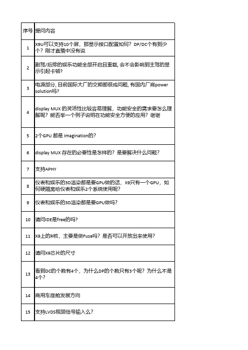
67
跟恩智浦的高端车载mcu相比目前能实现功能和安全完全替代 吗?具体将一些比较呢?
68 对于FHTI故障处理时间间隔有定义么?
69 请问X9可以支持到多少个屏幕;
70 X9比高通8155在性能上有哪些优势?
71 X9, V9是多少纳米的制程?
72 请问X9芯片是否已经量产;
73
在GPU上训练的AI模型要导入芯驰的AI加速器需要什么步骤, 多 久的开发周期
107 芯驰科技的X9智能座舱方案有哪些优势特点?
回复内容
X9U 最高是可以支持到 12 个屏,有 4 路 MIPI DSI,8 路 LVDS。有 6 个 DP 以及 8 个 DC. 相当于是 2 个 X9HP 不会的,我们是硬件隔离的,这反而是我们的优势。 如果是友商,所有的计算单元池化,只通过软件隔离,可能会导致卡 顿设置黑屏乃至死机。更多细节欢迎线下接洽,谢谢 满足系统上电时序要求即可。时钟域先上电,接着安全域上电,再接 着应用域上电。 x9系列永远不黑屏,因为DC会随时通过CRC校验检测视频流是否正 常,如果有问题,立即切换为R5功能安全域的内容,,当然也可以用 户自己来定义。大家,了解了display system之后,有更多自主方案; 更多细节欢迎线下接洽,谢谢 是的两个3D GPU都是imagination授权, 另外还有两个2D GPU是自研, Display MUX 主要是用来连接 DC 跟 Interface ,通过 Interface 将 DC 处 理后的显示数据进行选择,输出给到 例如 MIPI DSI 的显示接口
可以被动散热
与 DC 数量由关系,X9H 可接 4 个屏幕。
支持 LPDDR4X,目前不支持lpddr5
可以
一个
我们在架构和实际设计中考虑到这些了,请放心采用。谢谢,如果有 更多细节欢迎线下接洽,谢谢
W9412G6JH-5I;中文规格书,Datasheet资料

Read Operation............................................................................................................. 12 Write Operation ............................................................................................................. 13 Precharge ..................................................................................................................... 13 Burst Termination ......................................................................................................... 13 Refresh Operation ........................................................................................................ 13 Power Down Mode ....................................................................................................... 14 Input Clock Frequency Change during Precharge Power Down Mode ........................ 14 Mode Register Operation .............................................................................................. 14 Publication Release Date: Nov. 29, 2011 Revision A03
杰理解码芯片型号-概述说明以及解释

杰理解码芯片型号-概述说明以及解释1.引言1.1 概述杰理解码芯片是一种在数字信号处理领域有着广泛应用的集成电路芯片。
其主要功能是将数字信号进行解码和转换,从而实现音频、视频等多媒体数据的解码和播放功能。
杰理解码芯片具有高性能、低功耗、稳定性高等特点,被广泛应用于无线音频设备、家庭影音系统、汽车音响等领域。
本文将对杰理解码芯片的型号进行深入了解,探讨其特点、应用及未来发展趋势,希望能为读者提供更全面的了解和认识。
1.2 文章结构本文将首先介绍杰理解码芯片的概念和背景,包括其在音频领域的应用和重要性。
接着,将详细分析杰理解码芯片的特点,比如其技术参数、性能优势和市场竞争力。
然后,将探讨杰理解码芯片在不同领域的应用,包括音频播放器、无线音响和汽车音响系统等方面。
最后,将总结本文的主要观点,展望杰理解码芯片的未来发展,并提出对相关领域的建议和展望。
通过以上结构,读者可以全面了解杰理解码芯片的相关知识和应用领域,为进一步研究和应用提供参考和指导。
1.3 目的:本文旨在深入探讨杰理解码芯片的型号和特点,帮助读者更好地了解这一技术并应用到实际生活中。
通过对杰理解码芯片的介绍和应用,读者可以更全面地了解它的作用和价值,从而为未来的技术发展和应用提供参考和启示。
同时,希望通过本文的阐述,引发读者对杰理解码芯片的兴趣,促进技术创新和发展。
容2.正文2.1 了解杰理解码芯片杰理解码芯片是指由杰理公司研发生产的一种集成电路芯片,主要用于音频解码和播放。
杰理解码芯片采用先进的技术和设计,具有高性能、低功耗、稳定性强等优点。
杰理解码芯片在音频处理方面具有优秀的性能,能够支持多种音频格式的解码和播放,如MP3、WAV、FLAC等。
同时,杰理解码芯片还具有丰富的接口和功能,可以与各种外部设备和模块进行连接和控制,实现更加灵活和多样化的应用。
除此之外,杰理解码芯片还具有良好的兼容性和稳定性,能够保证音频数据的快速解码和稳定播放,为用户提供优质的音乐体验。
九极光一体机配置参数详解
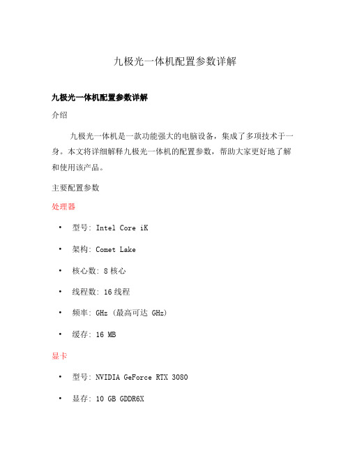
九极光一体机配置参数详解九极光一体机配置参数详解介绍九极光一体机是一款功能强大的电脑设备,集成了多项技术于一身。
本文将详细解释九极光一体机的配置参数,帮助大家更好地了解和使用该产品。
主要配置参数处理器•型号: Intel Core iK•架构: Comet Lake•核心数: 8核心•线程数: 16线程•频率: GHz (最高可达 GHz)•缓存: 16 MB显卡•型号: NVIDIA GeForce RTX 3080•显存: 10 GB GDDR6X•核心频率: GHz (最高可超频至 GHz) •接口: 3 x DisplayPort, 2 x HDMI 内存•容量: 32 GB DDR4•频率: 3200 MHz存储•固态硬盘: 1 TB NVMe PCIe•硬盘: 2 TB HDD显示屏•尺寸: 27 英寸•分辨率: 2560 x 1440•刷新率: 144 Hz•技术: IPS其他配置•操作系统: Windows 10•网络: 有线和无线网络支持•音频: 内置扬声器和麦克风•连接接口: USB , USB-C, HDMI, DisplayPort, RJ45优势和特点强大的处理性能九极光一体机搭载了高性能的Intel Core i7处理器,拥有多核心和多线程的能力,能够处理各种复杂的任务和多线程应用。
卓越的图形性能配备了NVIDIA GeForce RTX 3080显卡的九极光一体机,能够提供出色的游戏和图形渲染性能,为用户带来流畅的游戏体验和震撼的视觉效果。
大内存和存储空间32 GB的DDR4内存和巨大的存储空间(1 TB SSD + 2 TB HDD)使得九极光一体机能够同时运行多个应用,并存储大量的文件、游戏和媒体内容。
高清显示和流畅操作27英寸的IPS显示屏提供了144 Hz的刷新率和2560 x 1440的高分辨率,呈现出清晰细腻的图像和生动逼真的色彩。
并且九极光一体机的操作系统为Windows 10,提供了友好的用户界面和流畅的操作体验。
长虹电视机型号说明
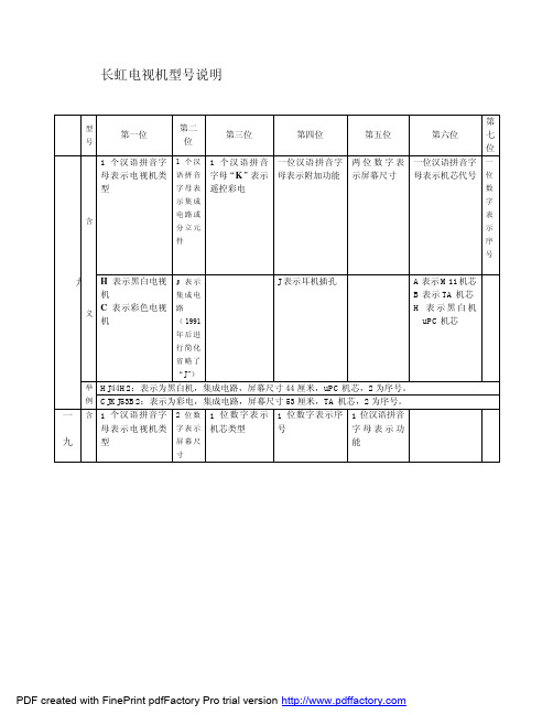
型
第一位
号
第二 位
第三位
第四位
第五位
第
第六位
七
位
1 个汉语拼音字 1 个汉 1 个 汉语拼 音 一位汉语拼音字 两 位 数 字 表 一位汉语拼音字 一
母表示电视机类 语拼音 字母“K”表示 母表示附加功能 示屏幕尺寸 母表示机芯代号 位
型
字 母 表 遥控彩电
数
示集成
字
电路或
表
含
分立元
喜
始使用)
尺寸 的派生产品
PDF created with FinePrint pdfFactory Pro trial version
A 表示 A6 机芯
一
D 表示 TDA 机芯
N -6 机芯
T 表示 CN-7 及
九
H 表示黑白电视
机
二
C 表示彩色电视
机
年
后
义
1 为 NC-3 机芯 2 为单片集成
电路黑白机 3 为 NC-3 机芯 4 为 M11 机芯 5 为 A3 机芯 6 为 TA 机芯 8 为 NC-2 机芯 9 为 TDA 机芯 0 为数字机芯
同一类型电视, 造型不同用序号 区分
S 为 S 端子 P 为射频画中
一 含 1 个汉语拼音字 2 位数 1 位 数字表 示 1 位数字表示序 1 位汉语拼音
母表示电视机类 字表示 机芯类型
号
字母表示功
九
型
屏幕尺
能
寸
PDF created with FinePrint pdfFactory Pro trial version
举 D2965A:D 表示 TDA 机芯,29 表示屏幕尺寸,65 表示机壳代号,A 表示该电视是 D2965 的派生
创佳彩电产品介绍按功能
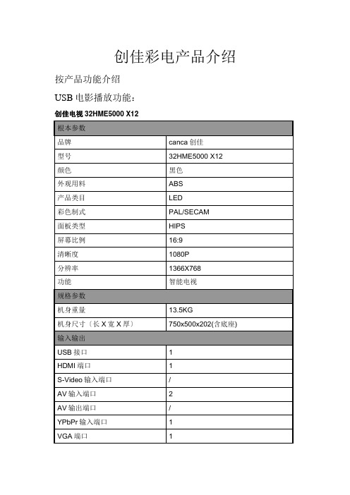
创佳彩电产品介绍按产品功能介绍USB电影播放功能:创佳电视32HME5000 X12创佳电视42LWE6300 F1创佳电视19HDE3000 V6创佳电视32HME8000 R35创佳电视22HZE9000 C68创佳电视32HZE9000 C68创佳电视19HZE9000 C68创佳电视26HZE9000 C68创佳电视32LME7000 T25创佳电视43HPD6000 K91创佳电视40HZE9000 C68创佳电视46HZE9000 C68创佳电视32LME8800 E6创佳电视51HPD6000 K91创佳电视22HDE3000 V655HZE9000 C6839HWE6300 F1创佳电视32HDE3000 V6创佳电视40LME8800 E6互联网电视功能:创佳电视32HME5000 X12创佳电视32LME8800 E6创佳电视40LME8800 E6电视/显示屏两用功能:创佳电视32HME5000 X12创佳电视19HDE3000 V6创佳电视22HZE9000 C68创佳电视32HZE9000 C68创佳电视32LME7000 T25创佳电视40HZE9000 C68创佳电视46HZE9000 C68创佳电视32LME8800 E6创佳电视22HDE3000 V6创佳电视 55HZE9000 C68创佳电视32HDE3000 V6创佳电视40LME8800 E6超窄边电视功能:创佳电视42LWE6300 F1创佳电视32HME8000 R35创佳电视32LME7000 T25创佳电视39HWE6300 F1内容总结。
创维彩电遥控器型号对照表
创维彩电遥控器型号对照表创维彩电遥控器型号对照表遥控器型号彩电型号3N01 1418-5000等4N04 2198-5000 2128-5000等2198-5000 2128-5000等5130 29S19000等5N20 25ND9000A 25ND9000A丽音 25NF8800A 25NF8800A 丽音25TF8000丽音25TH9000丽 25TM9000丽音 29SH8000丽音29TH9000丽音 8000-2599A 8000-2599A丽音5A01 8259 8298 8298AF 2140 2150 及大多数CPU使用CTV222X PCA84XXX的机型3P20 21ND9000A 21NF8800A 21N19000 21NK9000 21TH9000 21TI9000 21TN9000 21TR9000 8000-2122A 8000-21993418WF等5P03 CPU采用47-0000(1~7)-42的所有21" 25" 29" 34" 38" 等机型5P10 34SD9000等5P20 29HD9000 34SD9000 29TF8000 34NH8000 34HD8000 34SD9000 34SD9000丽音 8000-2522 8000-2522A 8000-2599A 8000-2922 8000-2922 8000-2998WF 8000-3498WF等5P21 5P30 29HD900 29HI9000 29TAF9000 29TI9000 29TM9000 29TP9000 34SD9000 34SG9000 34SI9000 34SP9000 34TI9000 34TP9000 34TP9000 8000-2922 8000-2922A8000-2998WF等5S01 2588-8000S 29F1NW等5S10 29SH8800等4S01 2128 2108等4S02 2108-3008 2140-3008 2188-8000S等3S28 21NF9000 21TM9000 21NF8800A等5S28 25NF9000 25NX9000 25TM9000 29SX9000等5101 29TMDA29SDDV等5D01 2982-100Hz等4T01 2122-8000T 2199-8000T等5T03 2588-8000T 2582-8000T等5T20 25ND9000 25NF8800 25NF8800A25NL9000 25TF8000 29HD9000 29NL900029SF8000 29SF8800 29SH8000 29SH880029TA8000 29TF8000 29TG9000 29TH90008000-2522 8000-2922等5T21 25ND9000 25ND9000A 25NF8800A 25TH900029HD9000 29SG9000 29SH8000 29SH9000 29TG900029TI9000 29TM9000等4T20 8000-2198等3T20 14NS9000 21ND9000 21NL9000 8000-1422 8000-2122 8000-2122A 8000-2199等3T21 21NL9000 8000-2122A等3T30 21ND9000 21NF9000 21NS9000 21TB900021TI9000 21TM9000 21TR9000等4Y01 2198-8000Y2122-8000Y等3Y20 14NS9000 21ND9000 21ND9000A 21NF8800A 21NI9000 21NK9000 21PS9000 21TB900021TH9000 21TI9000 21TM9000 21TN90008000-1422 8000-1422 8000-2122 8000-2122A8000-2199 8000-2199A等5D20 29TIDP 29TJDP 29TMDP 34TIDP34TJDP 34TPDP/34JPDP等5D25 29TMDP 34TIDP 34TPDP/34JPDP5D26 29T66DP 29TMDP 34TIDP 34TPDP/34JPDP 5D60 29HIDA 29TBDA29TKDA等5D66 29TBDP 29TKDP等5D70 29TIDP 29TJDP 291PDP 29TWDP等5D76 29T61DP 29TPDP等5D90 29T62D1 29TA1D1 29TKDI等5T25 25ND9000 25NX9000 25TH9000 25TI900025TM9000 29HI9000 29SG9000 29SI900029SX9000 29TH9000 29TI9000 8000-2522A等5T28 25TM9000 29SP9000 29TI9000 29TM9000等5T30 25NI9000 25TI9000 25TM9000 29SP900029TI9000 29TM900029TP9000等5T10 25TF80005M10 29TFDP 29TIDP 29TJDP等5D30 29TMDP等4A01 CPU采用菲利普CTV222X-XX及PCA84XX-XX PCA440-Axx等的大部分机型5K01 早期少量试产机型,产量很少,只有2928等几个型号5Y21 25ND9000A29SF9000 29SH8000 29TH9000 8000-2982A 5Y30 25ND9000 25ND9000A 25SM9000 29SX900029TH9000 29TM9000 29TX9000发射器型号IC电路对应处理器适用彩电机型大创维14号SAA3010 2210 3D36大创维15号5N20 9028-023 9D38 数码8000-2599A大创维16号9028-023 9D35大创维17号4N10 PT2213 9D29 8000T-2522 2922创维P1 5T20 PT2213 2E30 29NL9000 25NF8800 25NL9000 29SH8000 25ND9000 25TF800029HD9000创维P2,5T21 PT2213 9E35 25ND9000 25ND9000A25NF8800A25TH9000 29HD9000 29SG9000 29SH8000创维P3,5P20/4P02 SAA3010 25NF8000,29SH9000,8298DXA数码8000-2522 2922 2939 8E36创维P4 5P10 SAA3010 29T 1930 343P9000创维P5,5Y21 SAA3010 25ND9000 5800-F22109-00 3418创维P6,5T03 TC-9028-023 4N01创维P7,5D25 9028 4T01 2122-8000T,2199-8000T 2199A 8000T-2140/A创维P8,3E35 3010 5P30 同5P21,29HD9000 29TI9000创维P9,3E37 PT2210 3010 5D70 29TIDP,29DTDP,29TPDP,29TWDP创维P10,8E34 8521 5P10 343P9000创维P11,3E30 OT22103010 5P21 29HD9000 29HI9000 29TAF9000 29TI9000 29TK900029TM9000 34TP9000 8000-2922 2922A 2998WF 34SG9000 34SI9000创维P12 4D30 9028 863320A 2588-8000S 29FINW创维P13 5Y30 PT2210,3010 3E34 21ND9000A 21TAB8000 25ND9000 25NF9000创维P14,9E37 2213 9012 3T30 21ND9000 21NF9000 21TR9000创维P15。
x9dplus说明书
X9D PLUS 中文说明书1 遥控器菜单设置1.1 主画面1.1.1 主画面第一页开机后首先看到的就是主画面,主画面有四页,通过按遥控器MENU进行循环切换。
下面是首页的说明,说明顺序按照从遥控器屏幕的最上方到最下方。
7.6v遥控器电池电压,X9D使用6节镍氢电池小电池图标遥控器电池电量图标,显示电量剩余量。
->设置电量图标范围喇叭图标遥控器喇叭总音量。
->设置音量07:10当前时间。
->设置时间MODEL01模型名字 ->模型名字SA↑ SE ↑当前遥控器开关状态,例如SA↑表示SA开关拨到上方,SA-表示SA开关拨到中间等。
开关共有8个,SA-SH,其中SF为2档开关,SH为弹簧开关,其余均为三档开关。
开关的可以自定义,默认没有任何功能,开关可以用来直接控制舵面,如收放起落架,也可以定义为其他功能,比如改变飞行模式,调整大小舵,重设秒表,语音播报回传电压值,锁定油门…等等。
图片此处是您的模型的图片,可以在此处进行设置左右两侧较粗的竖条当前遥控器旋钮状态(左上:S1 右上:S2 左下:LS 右下:RS)。
旋钮的功能是自定义的,默认没有任何功能。
旋钮可以用来直接控制舵面,比如控制襟翼开启角度,也可以定义为其他功能,比如控制音量,控制方向舵-副翼混控比例,微调前起落架方向与方向舵混控的角度…等等左右和下方较细的竖条微调位置。
分别对应摇杆四个方向的微调。
[右方秒表]如果设置了秒表,在主画面右方会看见秒表,可以在此处进行设置1.1.2 主画面第二页在主画面第一页按PAGE进入主画面第二页,左右多出两个方框用来显示当前左右摇杆的位置,并且省略了秒表的显示。
其余与主画面第一页相同。
1.1.3 主画面第三页在主画面第二页按PAGE进入主画面第三页,右侧多出了一些下划线,用来显示LS1-LS32虚拟开关位置,当虚拟开关打开时,下划线会显示为竖条。
->虚拟开关。
并且省略了秒表的显示。
超微X9DAi参数
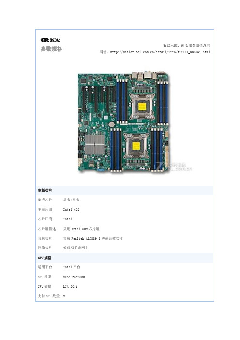
超微X9DAi参数规格数据来源:西安服务器信息网网址:/detail/1775/177441_334551.html主板芯片集成芯片显卡/网卡主芯片组Intel 602芯片厂商Intel芯片组描述采用Intel 602芯片组音频芯片集成Realtek ALC889 8声道音效芯片网络芯片板载双千兆网卡CPU规格适用平台Intel平台CPU种类Xeon E5-2600CPU插槽LGA 2011支持CPU数量 2总线频率QPI 8.0GT/s内存规格内存类型DDR3内存描述支持DDR3 1600/1333/1066/800内存,最大支持16条内存,最大支持512GB 扩展插槽显卡插槽3×PCI-E 3.0 x162×PCI-E 3.0 x81×PCI-E 3.0 x4(in x8)SATA接口8个SATAII接口;2个SATAⅢ接口I/O接口USB接口7×USB2.0接口;4×USB3.0接口PS/2接口PS/2键鼠通用接口并口串口1个串口外接端口2×RJ45网络接口1×1394接口音频接口板型主板板型EATX板型外形尺寸30.5cm×33.2cm软体管理BIOS性能128Mb SPI Flash EEPROM with AMI BIOS 其他特征其他特点SATA 2.0 3Gbps with RAID 0,1,5,10 SATA 3.0 6Gbps with RAID 0,1,5,10其他参数电源插口两个八针,一个24针电源接口数据来源:西安服务器信息网()。
UV喷码机设备功能具体参数

广州将维UV喷码机实现远程控制,远程信息输入、远程控制开关机,让自动化程度更高,让喷码标识设备拥有更高价值。
将维JW-5000理光UV喷码机已经在食品、包装、印刷、饮料、化肥、农药、种子、建材等各种领域上得到了广发的应用,并且得到了客户高度的认可与赞誉。
设备型号:JW5000UV喷码机喷头型号:理光Ricoh GEN5 54宽喷头标签高度:54毫米标签长度:2400毫米打印单元数:8组打印精度:横向600dpi,纵向200-1200dpi可调速度:228米/分钟工作分辨率:600*300dpi/600*600dpi每升墨水打印条码:80万个(对应36mm*8mm的监管码)条码级别:99%以上A级打印软件:JETWELLS专用排版打印软件借口类型:高速USB3.0或网线接口打印能力:可打印各种可变数据。
包括数字字母、一维码、二维码、图案、图形或根据客户定制开发的特殊内容。
打印材质方式:卷材或单张适合打印材质:各种纸张、塑料、PVC/PP/PE薄膜、金属、玻璃等。
墨水类型:环保型水性或UV固化油墨打印颜色:单色或彩色可选广州将维UV喷码机优势使用寿命长:喷头采用全金属设计,喷嘴表面镀金,极大的提高了喷头使用寿命,是目前市场上最先进的DOD工业喷头。
打印速度快:喷头打印频率能达到33KHZ,是普通喷头的2到4倍。
在不同分辨率下能实现60-150M/min的高速生产。
打印精度高:水平打印精度高达500DPI,打印的条码外观饱满,黑亮,精细。
特别适合各种白卡,灰卡纸的打印。
在70M/min稳定生产时,条码是99%以上都是A级。
使用成本低:单个条码的生产成本在1.5厘左右产品使用期间终生提供免费喷头保养和清洗服务。
排版功能强:排版方式灵活高效,节约纸张通过喷头组件双排安装,可以实现在版面上的无缝打印。
防重码功能:打印系统自带重码报警功能,从源头上避免重码的发生。
已打印过的数据文件禁止打印对打印过的数据在打印之前自动提示广州将维UV喷码机成功案例1.徐福记物流码多家外箱纸箱厂喷印一维条码2.恒丰动保等兽药二维码3.白云山制药,哈药,齐都药业,科伦制药等等药厂的药品电子监管码一级二级码赋码4.中山伙伴机械有限公司配套的制袋机有多套设备在运行中5.山东凯丽特种纸喷防伪码6.承德露露杏仁露喷抽奖码7.景田百岁山泉喷外箱二维码8.百威;雪花啤酒喷印二维码9.王老吉外箱二维码10.光明牛奶;燕塘牛奶外箱二维码11顺德酒厂白酒内箱抽奖二维码广州将维公司(JetWells)主要提供服务于:UV侧喷可变数据喷码系统、中速标签可变数据喷码系统、高速标签可变数据喷码系统、UV 瓶盖可变数据喷码系统、单张走纸可变数据喷码系统、药盒可变数据喷码系统、软包装可变数据喷码系统、高速在线可变数据喷码系统、UV彩色可变数据喷码系统、纸箱可变数据喷码系统、水性喷码机、配套标识自动化、跟踪防伪系统、防窜货系统、LED水冷固化系统、二维码检测剔除、采集关联等,能满足几乎所有标识喷墨技术,广泛适合各行业产品标识喷码,将维坚持以现代高科技喷码产品服务各行各业。
韩酷平板电脑M9的资料介绍

韩酷平板电脑M9的资料介绍韩酷平板电脑(M9)1、基本情况产品图片:品牌:韩酷产地:中国2、基本参数和基本性能。
技术规格型号M9处理器Via(威盛)8505+,主频400M内存128MB DDRII SDRAM内置硬盘2GB的FLASH外置存储器(用户自选) 最大可支持8GB ,为TF卡槽,只支持TF 卡无线网卡内置WIFI,支持标准的802.11b/g有线网络连接(选配)支持标准RJ45网络连接,但客户需自购或选配:USB转RJ45口连接器。
3G网络连接(选配)需自配USB口的外置3G上网卡。
LCD显示屏7”TFT LCD高清数字屏,分辨率800×480。
触摸屏高灵敏度电阻触摸屏电池内置1500mAH锂电池,充满电后续航90分钟以上(亮度适中,音量适中,视频播放情况下)输入工作电压/电流9V/1.5A温度工作温度:0。
C ~ 60。
C,存放温度:-20。
C ~80。
C重量398克颜色金属银外观规格202×135×14mm(长×宽×厚)。
导航功能无。
不带GPS模块USB接口USB 2.0 MINI USB接口。
带转接为标准USB口的连接线。
装箱配件主机、转接为标准USB口的连接线线、220v充电器、用户手册、保修卡、耳机、合格证。
功能及特征软件系统谷歌Android 1.9语言英文,中文简体输入法支持全屏手写等多种输入法,支持中文输入视频播放支持.wmv,.mpg, MP4和.avi文件格式的MP4播放,可调节播放进度、暂停音乐播放支持MP3,WMA,WAV格式图片浏览支持JPG、BMP、GIF格式的图片浏览,支持幻灯片方式切换,图片缩放,全屏图片拖动文本阅读支持txt格式的电子文本,随时随地阅读您喜爱的书籍自行安装软件支持客户自行安装android软件(后缀为.APK的软件安装包)摄像头支持外置的USB摄像头QQ软件自带手机QQ软件办公软件Word,excel,pdf,ppt自带浏览器自带电子邮件自带视频自带土豆视频。
9路双线LED控制驱动芯片MX5109
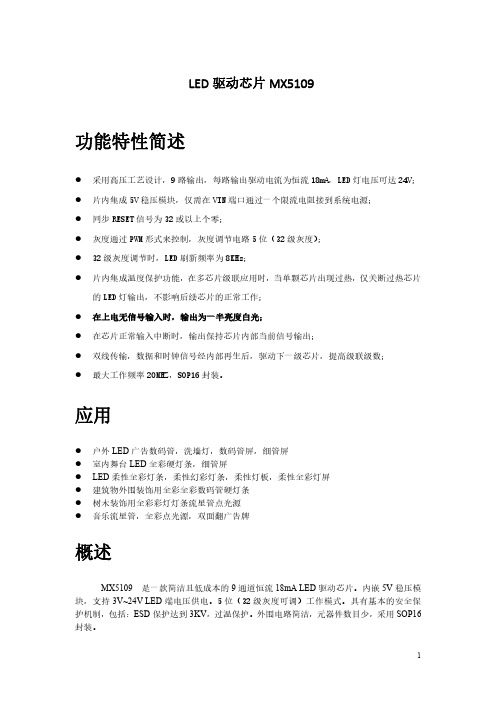
LED驱动芯片MX5109功能特性简述●采用高压工艺设计,9路输出,每路输出驱动电流为恒流18mA,LED灯电压可达24V;●片内集成5V稳压模块,仅需在VIN端口通过一个限流电阻接到系统电源;●同步RESET信号为32或以上个零;●灰度通过PWM形式来控制,灰度调节电路5位(32级灰度);●32级灰度调节时,LED刷新频率为8KHz;●片内集成温度保护功能,在多芯片级联应用时,当单颗芯片出现过热,仅关断过热芯片的LED灯输出,不影响后续芯片的正常工作;●在上电无信号输入时,输出为一半亮度白光;●在芯片正常输入中断时,输出保持芯片内部当前信号输出;●双线传输,数据和时钟信号经内部再生后,驱动下一级芯片,提高级联级数;●最大工作频率20MHZ,SOP16封装。
应用●户外LED广告数码管,洗墙灯,数码管屏,细管屏●室内舞台LED全彩硬灯条,细管屏●LED柔性全彩灯条,柔性幻彩灯条,柔性灯板,柔性全彩灯屏●建筑物外围装饰用全彩全彩数码管硬灯条●树木装饰用全彩彩灯灯条流星管点光源●音乐流星管,全彩点光源,双面翻广告牌概述MX5109是一款简洁且低成本的9通道恒流18mA LED驱动芯片。
内嵌5V稳压模块,支持3V~24V LED端电压供电。
5位(32级灰度可调)工作模式。
具有基本的安全保护机制,包括:ESD保护达到3KV,过温保护。
外围电路简洁,元器件数目少,采用SOP16封装。
应用电路原理图注意:芯片内部需要从SVCC引脚提供的功耗约为2mA左右,所以R1的值取决于VCC电压值;当VCC大于5V时,R1应遵从如下公式:(VCC–5V)/R1>2mA(在VCC小于5V时,R1应该尽量小)。
建议值:5V电路51-100欧姆,12V电路2K-3.5K欧姆,24V电路5K-10K欧姆。
C1为滤波电容,可大可小,可选104,建议值为1uF。
Rext为产生基准电流源的外接电阻,在一定范围内Rext与驱动电流Iout遵从如下公式:1.31v/Rext=Iout/137.4;当Rext取值10K欧姆时,驱动电流Iout为18mA,当Rext取值15K欧姆时,驱动电流Iout为12mA。
- 1、下载文档前请自行甄别文档内容的完整性,平台不提供额外的编辑、内容补充、找答案等附加服务。
- 2、"仅部分预览"的文档,不可在线预览部分如存在完整性等问题,可反馈申请退款(可完整预览的文档不适用该条件!)。
- 3、如文档侵犯您的权益,请联系客服反馈,我们会尽快为您处理(人工客服工作时间:9:00-18:30)。
COMMENT
Stresses above those listed under “Absolute Maximum Ratings” may cause permanent damage to the device. This is a stress rating only; the functional operation of the device (at these or any other conditions above those listed in the operational sections of this specification) is not implied. Exposure to absolute maximum rating conditions for extended periods may affect device reliability.
Each potentiometer is connected as a two-terminal variable resistor and can be used in a wide variety of applications including:
– bias and gain control
30kΩ 30kΩ
Control and
Memory
Control and
Memory
RH1 RL1 RH2
RL2
VSS (Ground)
1
CAUTION: These devices are sensitive to electrostatic discharge; follow proper IC Handling Procedures.
元器件交易网
®
Data Sheet
March 4, 2005
X93255
FN8187.0
Dual Digitally Controlled Potentiometers (XDCPs™)
FEATURES
• Dual solid-state potentiometers • Independent Up/Down interfaces • 32 wiper tap points per potentiometer
with respect to VSS .............................. -1V to +6.5V Lead temperature (soldering 10 seconds) ......... 300°C Maximum reflow temperature (40 seconds) ...... 240°C Maximum resistor current ..................................... 2mA
Symbol RTOT VR
RW IW
CH/CL/CW
Parameter
End to end resistance RH, RL terminal voltages Power rating Noise Wiper Resistance Wiper Current Resolution Absolute linearity(1) Relative linearity(2) RTOTAL temperature coefficient Potentiometer capacitances
RECOMMENDED OPERATING CONDITIONS
Temperature Industrial
Min. -40°C
Max. +85°C
Supply Voltage (VCC) X93255
Limits 5V ± 10%(7)
POTENTIOMETER CHARACTERISTICS (Over recommended operating conditions unless otherwise stated.)
• RTOTAL value = 50kΩ • Packages
—14-lead TSSOP
DESCRIPTION
The Intersil X93255 is a dual digitally controlled potentiometer (XDCP). The device consists of two resistor arrays, wiper switches, a control section, and nonvolatile memory. The wiper positions are controlled by individual Up/Down interfaces.
3
FN8187.0
March 4, 2005
元器件交易网
X93255
D.C. OPERATING CHARACTERISTICS (Over recommended operating conditions unless otherwise specified.)
Symbol ICC1 ICC2 ISB
Min. 37.5
0
Limits
Typ. Max. Unit
Test Conditions/Notes
50
62.5 kΩ (5)
-120
VCC 1
V mW(7) dBV(7)
(5) RTOTAL = 50kΩ (5) (6) Ref: 1kHz(5) (6)
1000 Ω (5) (6)
0.6
mA (5) (6)
(2) Relative linearity is a measure of the error in step size between taps = RH(n+1) - [RH(n) + Ml] = ±0.5 Ml, n = 1 .. 29 only. (3) 1 Ml = Minimum Increment = RTOT/31. (4) Typical values are for TA = 25°C and nominal supply voltage. (5) This parameter is only applies to a single potentiometer
Symbol DNC RL1 CS1 INC2 U/D2 RH2 VSS DNC RL2 CS2 VCC INC1 U/D1 RH1
Do Not Connect. Low Terminal 1. Chip Select 1. Increment 2. Up/Down 2. High Terminal 2. Ground. Do Not Connect. Low Terminal 2. Chip Select 2. Supply Voltage. Increment 1. Up/Down 1. High Terminal 1.
• Low power CMOS —VCC = 5V ± 10% —Active current, 200µA typ. —Standby current, 4µA max
• High reliability —Endurance 200,000 data changes per bit —Register data retention, 100 years
1-888-INTERSIL or 1-888-352-6832 | Intersil (and design) is a registered trademark of Intersil Americas Inc.
XDCP is a trademark of Intersil Americas Inc. Copyright Intersil Americas Inc. 2005. All Rights Reserved
—Wiper position stored in nonvolatile memory and recalled on power-up
• 31 resistive elements per potentiometer —Temperature compensated —Maximum resistance tolerance ± 25% —Terminal voltage, 0 to VCC
(6) This parameter is guaranteed by characterization.
(7) When performing multiple write operations, VCC must not decrease by more than 150mV from its initial value.
All other trademarks mentioned are the property of their respective owners.
元器件交易网
PIN CONFIGURATION
X93255
TSSOP
DNC*
RL1
CS1 INC2 U/D2 RH2 VSS
A potentiometer is implemented by a resistor array composed of 31 resistive elements and a wiper switching network. The position of each wiper element is controlled by a set of independent CS, U/D, and INC inputs. The position of the wiper can be stored in nonvolatile memory and then be recalled upon a subsequent power-up operation.
3
±35 10/10/25
