GPS模块使用说明
BDS GPS 双系统精密授时模块用户手册说明书

MXT902Copyright © 2015-2017Wuhan Mengxin Technology Co., Ltd.BDS/GPS 双系统 精密授时模块 用户手册修订记录对产品的特定用途适用性、适销性或对任何专利权、版权或其它知识产权的侵权责任等,均不作担保。
若不按手册要求连接或操作产生的问题,本公司免责。
武汉梦芯科技有限公司可能随时对产品规格及产品描述作出修改,恕不另行通知。
对于本公司产品可能包含某些设计缺陷或错误,一经发现将收入勘误表,并因此可能导致产品与已出版的规格有所差异。
如客户索取,可提供最新的勘误表。
版权所有© 2015-2017,武汉梦芯科技有限公司。
保留所有权利。
目录产品介绍 (1)1.1概述 (1)1.2 主要特征 (1)1.3 应用 (1)1.4 性能指标 (2)PIN脚功能描述 (3)2.1 PIN脚示意图 (3)2.2 PIN脚定义 (4)电气特性 (5)3.1 绝对最大值 (5)3.2 运行条件 (5)3.3 工作环境 (6)传输及外设接口 (6)4.1 PPS (6)4.2 I2C (6)4.3 UART (6)4.4 GPIO (6)4.5 EXTINT (6)默认配置 (6)5.1 串口设置(CFGPRT) (6)5.2 消息设置(CFGMSG) (7)5.3 导航系统设置(CFGNAV) (7)5.4 授时输出参数配置(CFGTPO) (7)5.5 时间脉冲模式设置(CFGTPM) (8)5.6 卫星系统配置(CFGSYS) (8)授时特性 (8)机械规格 (8)包装及运输 (9)8.1 包装 (9)8.2 ESD防护 (9)订购信息 (10)参考设计 (10)10.1 设计注意事项 (10)10.2 天线 (11)10.3 串口 (12)10.4 参考设计原理图 (13)10.5 参考设计PCB封装 (14)10.6 推荐炉温曲线 (15)产品介绍1.1 概述武汉梦芯科技有限公司设计生产的 MXT902 BDS/GPS双系统精密授时模块,基于公司完全自主知识产权的高精度消费类导航定位SoC芯片,能够同时支持 BDS B1、GPS L1 两个频点。
如何使用gps模块?从头到尾,详细讲解和程序说明

如何使用gps模块?从头到尾,详细讲解和程序说明GPS 模块是全球定位系统的一种实现方式,是一种位置信息获取的设备。
GPS 模块通过透过设备信号,可将设备所在的位置、速度和时间等信息准确传达给用户。
GPS 模块的使用主要包括以下几个步骤:1. 确认 GPS 模块和设备连接正常在开始使用 GPS 模块前,需要先确认 GPS 模块和设备之间的连接是否稳定。
这一步需要确认各种接口是否正确连接并且是否适合使用。
2. 配置 GPS 模块GPS 模块需要进行配置后才能正常使用,因为不同的模块具有不同的协议,所以需要根据模块的使用手册进行配置。
配置可以通过串口通信实现,用户需要根据模块的指令手册完成配置。
3. 获取位置信息当 GPS 模块已经连接并且配置完成后,就可以开始获取位置信息了。
使用 GPS 模块的淘宝例程来获取经度和纬度:```arduino#include <TinyGPS++.h> // 导入 TinyGPS++ 的库TinyGPSPlus gps;void loop() {while (Serial.available()) {gps.encode(Serial.read());}if (gps.location.isUpdated()) { // 检测是否更新Serial.print("Latitude= ");Serial.print(t(), 6);Serial.print(" Longitude= ");Serial.println(gps.location.lng(), 6);}delay(1000);}```上述程序首先导入 TinyGPS++ 的库,然后初始化 TinyGPSPlus 对象。
在主循环中,使用 `Serial.available()` 检测串口是否有数据,然后调用 `gps.encode()` 来解码接收到的数据。
GPS 北斗定位模块说明书

GPS/北斗定位模块说明书GPS/北斗定位模块使用说明书V2.4济南智泽贸易有限公司目录1.产品介绍 (1)1.1.产品概述 (1)1.2.产品特点 (1)1.3.技术指标 (1)1.4.产品尺寸 (1)1.5.硬件接口 (2)2.通信协议 (3)2.1.通信协议 (3)2.2.寄存器定义 (4)3.协议详解 (6)3.1.读保持寄存器 (6)3.2.读取版本号 (6)3.3.读取设备地址 (7)3.4.读取设备波特率 (7)3.5.读取奇偶校验位 (7)3.6.读取定位数据(RMC) (8)3.7.定位数据(RMC)解析 (8)3.8.修改设备地址(广播) (9)3.9.修改波特率 (9)3.10.修改奇偶校验位 (9)4.保修期限 (10)5.技术支持 (10)6.联系方式 (10)7.免责声明 (10)1.产品介绍1.1.产品概述GPS/北斗定位模块,是一款具有GPS定位和北斗定位的双模定位终端,可以快速、精确定位位置。
定位模块内含双模定位芯片,快速定位位置,并且将定位信息以RS485接口和Modbus协议的方式提供给用户使用,串口波特率最高可达115200bps,可以通过PC机设置软件或串口命令轻松控制,使用方便快捷。
1.2.产品特点⏹同时支持GPS定位和北斗定位⏹串口波特率自定义,支持2400~115200bps⏹串口支持全双工和半双工串口通讯,支持RS485收发自动切换⏹模块串口波特率等参数可通过PC机或串口命令配置⏹RS485带TVS、过流等保护⏹提供天线状态诊断,提供天线开路、短路等状态信息1.3.技术指标环境参数⏹工作温度:-40℃~80℃⏹工作湿度:5%~95%RH,无凝露供电⏹工作电压:DC5~28V⏹功耗:≤0.3W定位精度⏹出色的定位功能,支持BDS/GPS/GLONASS卫星导航系统的单系统定位,以及任意组合的多系统联合定位⏹冷启动捕获灵敏度:-148dBm跟踪灵敏度:-162dBm⏹定位精度:2.5米(CEP50)⏹内置天线检测及天线短路保护功能1.4.产品尺寸产品尺寸长x宽x高为:95mm x50mm x30mm,其中95mm包含长度80mm和两个安装孔15m图1-1产品尺寸1.5.硬件接口图1-2硬件接口硬件接口定义见表1-2硬件接口定义。
L76X GPS模块用户手册说明书

L76X GPS ModuleUser ManualOVERVIREThis is a general GNSS module which supports Multi-GNSS systems: GPS, BDS, and QZSS, with advantages such as fast positioning, high accuracy, low power consumption, and so on.SPECIFICATIONGPS⚫Band: GPS L1(1575.42Mhz), BD2 B1 (1561.098MHz)◼Channels: 33 tracking ch, 99 acquisition ch, 210 PRN ch◼C/A code◼SBA: WAAS, EGNOS, MSAS, GAGAN⚫Horizontal position accuracy:◼Autonomous: <2.5mCEP⚫Time-To-First-Fix @-130dBm (EASY™ enabled):◼Cold starts: <15s◼Warm starts: <5s◼Hot starts: <1s⚫Sensitivity:◼Acquisition: -148dBm◼Tracking: -163dBm◼Re-acquisition: -160dBm⚫Dynamic performance:◼Altitude (max): 18000m◼Velocity (max): 515m/s◼Acceleration (max): 4GGENERAL⚫Communication interface: UART⚫Baudrate: 4800~115200bps (9600bps by default) ⚫Update rate: 1Hz (default), 10Hz (max)⚫Protocols: NMEA 0183, PMTK⚫Power supply voltage: 5V / 3.3V⚫Operating current: 11mA⚫Operating temperature: -40℃~ 85℃⚫Dimensions: 32.5mm x 25.5mm INTERFACEOvervire (1)Specification (1)GPS (1)General (1)Interface (2)Hardware (4)Testing in PC (5)Demo codes (6)Download Demo code (6)Raspberry Pi examples (7)Copy examples (7)Libraries install (8)Enable serial port (9)Install MINICOM (9)Hardware connection (10)Running codes (11)Expected result (11)STM32 examples (12)Hardware connection (12)Expected result (12)Arduino examples (13)Hardware connection (13)Expected result (13)FAQ (14)1.L76X GPS Module on board resource2.L76B module3.RT9193-33: power manager4.Rechargeable MS621FE Li battery: for preserving ephemeris information and hot starts5.Ceramics active antenna6.GPS status indicator7.Power indicator8.PH2.0 5PIN connector9.GNSS antenna connector10.Backup mode wakeup jumper: not soldered by default, short the jumper to exit backup modeConnect GPS antenna to L76X GPS module, and wire it to USB to UART module. Connect USB to UART module to PC. PWR lights on after connecting.Open serial assistant software in PC. Select the correct COM port (according to the Device Manager), set baud rate: 9600, data bit: 1, stop bit: 1【Note】a) Please set the module or receiver of antenna outdoor for stable GPS signalb) Generally, first time module should use about 35s to locate (cold starting), the locating time (first) maybe longer even failed because of environment, please be patient.Download U-center software from wiki. Unzip it and install. Open U-center software, click Receiver menu, choose Port, and select the correct com port (refer to Devices Manager). Set baud rate: 9600 then click button to connect L76X GPS Module. U-center display information after connecting.If you want to check the area better, you can install GoogleEarthPluginSetup.exe tool, which allow you to choose Google Earth under View menu【Note】The result you get from Google Earth maybe different with actual area because of dynamic drift of GPSDEMO CODESThe demo code is set for 9600 and 115200 baudrate, make sure the baudrate of L76X GPS module is one of them if you use demo codes.DOWNLOAD DEMO CODEFind the product in Waveshare website, open the wiki and download demo code from wiki.Unzip:Arduino: Arduino examples based on Arduino UNORaspberry Pi: Raspberry Pi examples include wiringpi and python codesSTM32: STM32 examples based on STM32F103RASPBERRY PI EXAMPLESCOPY EXAMPLESInsert SD card (which has installed Raspbian image) to PC by card readerCopy Raspberry Pi examples ( the folder we download and unzip above) to BOOT directory of SD cardExit and insert the card to Raspberry Pi, then start.Check it: ls /bootCopy it to /home/pisudo cp -r /boot/RaspberryPi/ ./sudo chmod 777 -R RaspberryPi/LIBRARIES INSTALLExamples should be used with libraries installedInstall BCM2835:Download libraries from BCM2835 website:/mikem/bcm2835/【Note】xx is the version of libraries, for example, if the libraries you download is bcm2835-1.52. The command you should execute is sudo tar zxvf bcm2835-1.52.tar.gzInstall wiringPi:Install python:ENABLE SERIAL PORTUART interface should be used for communicating, so we need to enable hardware serial of Raspberry Pi.sudo raspi-configDisable login shell function and then enable hardware serialINSTALL MINICOMminicom is a serial assistant tool for Linux.Install minicom:sudo apt-get install minicomUsing minicom:minicom -D /dev/ttyS0 -b 9600【Note】If you use Raspberry Pi zero, the serial port should be ttyAMA0, you can confirm the port by command: ls -l /dev/serial0 The default baud rate of minicom is 115200, here we use parameters -b 9600 to set it as 9600If you want to exit, you can press Ctrl + A, press X and choose Yes, then Enter.HARDWARE CONNECTIONThe color of wire you get may be different with here, you should connect the module according to the silk screen printing.RUNNING CODESEnter RaspberryPi folder (The directory of example) and run it with commands: wiringPi code:python code:EXPECTED RESULTIt requires about 35s to locate (first time).Data printed first is original data.Time: L76X GPS Module output time.【Note】Even the default baud rate of L76X GPS Module is 9600, it is changed to 115200 in code. If you find that 9600 cannot work next time, please check if it is changed.STM32 EXAMPLESThe development board used here is Waveshare XNUCLEO-F103RB, whose chip is STM32F103RBT6. The code is based on HALHARDWARE CONNECTIONWire L76X GPS Module to STM32 board, and connect USB to UART (USART1) interface of STM32 board to PC【Note】Even the default baud rate of L76X GPS Module is 9600, it is changed to 115200 in code. If you find that 9600 cannot work next time, please check if it is changed.EXPECTED RESULTIt requires about 35s to locate (first time).Data printed first is original data.Time: L76X GPS Module output time.ARDUINO EXAMPLESThe development board used here is UNO PLUSHARDWARE CONNECTIONEXPECTED RESULTIt requires about 35s to locate (first time). Open serial monitor and set baud rate to 9600. Data printed first is original data.1.W hy the baud rate doesn’t change after send changing command?- Please check if the current baud rate is correct. If the satellites searched are too much, the module cannot allows the baud rate to be smaller. In this case, you can use SET_NMEA_OUTPUT command to reduce the output data per time and try again.2.Why the locating is not accurate?- The accuracy is influenced by environment. Weather reason: The humidity is every high when raining, which weaken the intensity of the GPS signal. It often raining in summer, therefore, the intensity of phone signals is weak. High building reason: high buildings shelter from satellite, make GPS intensity became weak. Area problem: Suburbs have less satellite coverage, so GPS intensity is weak in these areas. Interference problem: Sometime, signals from satellites will be interrupted by atmosphere ionosphere, buildings, forest, water and son on.3.Why the locating result is different with smart phone?- L76X GPS HAT use satellite locating. Smart phone use AGPS, LBS, WIFI and Bluetooth locating as well except satellite. Smart phone locate much faster. And the multi-satellite system used by smart phone are different with L76X’s4.How to exit from Backup mode?- Module output nothing if it enter Backup mode. You cannot exit from Backup mode even re-power. The only way to exit from Backup mode is that short R6 more than 0.5s。
gps坐标定位仪器怎么用

GPS坐标定位仪器怎么用1. 介绍GPS(全球定位系统)坐标定位仪是一种常见的定位工具,广泛应用于航海、地理测量、车辆追踪和户外活动等领域。
本文将介绍GPS坐标定位仪器的使用方法,包括如何打开并设置设备、获取GPS坐标、记录位置和导航等功能。
2. 打开设备和设置在开始使用GPS坐标定位仪器之前,首先需要打开设备并进行必要的设置。
步骤:1.检查电池电量:确保设备有足够的电量供使用,可以通过连接充电器或更换电池来满足需求。
2.打开GPS定位仪:按下设备上的电源按钮,通常位于侧面或顶部位置,以启动设备。
3.配置初始设置:根据设备的说明手册,设置一些基本参数,如语言、时间和日期设置等。
4.连接卫星:设备会自动搜索并连接卫星,确保设备在开阔的天空下,以便获得更准确的定位。
3. 获取GPS坐标一旦设备设置好并连接到卫星,就可以使用GPS坐标定位仪器获取当前位置的GPS坐标。
步骤:1.打开GPS定位仪:按下设备的电源按钮,等待设备启动,显示当前位置的GPS坐标。
2.确认位置:设备通常会显示当前位置的纬度和经度信息,有时还会提供其他信息,如海拔高度或速度等。
确认这些信息以确保位置准确。
3.记录坐标:如果需要记录当前位置的GPS坐标,可以将其保存到设备的内部存储器或外部存储卡中。
按照设备说明手册中的指导,执行相应的操作来记录坐标。
4. 导航功能大多数GPS坐标定位仪器还具有导航功能,可以帮助用户在旅行或户外活动中找到目的地。
步骤:1.打开导航功能:通过设备菜单或特定的导航按钮,进入导航模式。
2.输入目的地坐标:根据设备的操作界面,输入目的地的GPS坐标。
一些设备还支持通过地图或地址搜索来选择目的地。
3.导航开始:设备会计算最佳路线,并提供导航指示,例如方向指示、距离和预计到达时间等。
按照指示行驶,直到到达目的地。
5. 其他常见功能除了基本的定位和导航功能外,GPS坐标定位仪器还可以具备其他实用功能,例如以下示例:•轨迹记录:设备可以记录所经过的路径,并将其存储为轨迹文件。
GPS模块REB-3571使用说明
Available Baud Rate
The Specifications are subject to be changed without notice. Page 2 of 27
EB-3531
Channels Flash Sensitivity Cold Start Warm Start Hot Start Reacquisition Accuracy 20 4Mbit Tracking:-159dBm 42 seconds, average 38 seconds, average 1 second, average 0.1 second, average Position: 10 meters, 2D RMS 5 meters, 2D RMS, WAAS enabled Velocity: 0.1 m/s Time: 1us synchronized to GPS time < 18,000 meter < 515 meter/second < 4G 1 Hz WAAS, EGNOS, MSAS WGS-84 Interface I/O Pins Type Dimensions Power Supply Backup Voltage Power Consumption Humidity Range Operation Temperature Storage Temperature 2 serial ports Physical Characteristic 22-pin stamp holes 15 mm * 13mm * 2.2 mm ±0.2mm DC Characteristics 3.3Vdc ± 5% 2.0 ~ 3.6Vdc Acquisition: 42mA Environmental Range 5% to 95% non-condensing -30℃ to 85℃ -40℃ to 125℃
PmodGPS 位置定位模块说明书

1300 Henley CourtPullman, WA 99163509.334.6306PmodGPS™ Reference ManualRevised April 12, 2016This manual applies to the PmodGPS rev. AOverviewThe PmodGPS can add satellite positioning accuracy to any embedded system. The PmodGPS features a GlobalTop FGPMMOPA6H GPS antenna module that utilizes the MediaTek GPS MT3329.Features include:∙Ultra-sensitive GPS module (-165 dBm)∙Add 3m 2D satellite positioningaccuracy to any embedded system∙Low power consumption∙Up to 10Hz update rate∙NMEA (default) and RTCM protocolsavailable∙Small PCB size for flexible designs 2.0 in× 0.8 in (5.0 cm × 2.0 cm)∙6-pin Pmod port with UART interface∙Library and example code availablein resource centerThe PmodGPS.1 Functional DescriptionThe PmodGPS uses a standard 6-pin port and communicates via a 2-wire Universal Asynchronous Receiver/Transmitter (UART.) The PmodGPS also has a 2-pin port for control of the NRST pin to the module and the Radio Technical Commission for Maritime services, or RTCM pin for Differential Global Positioning System (DGPS) data using RTCM protocols.Note: The PmodGPS arrives with the RTCM feature inactive, to enable RTCM capabilities users should contact GlobalTop at: .2 Interfacing with the PmodThe PmodGPS uses UART protocol for data transmission and reception. The interface operates at a default baud rate of 9.6 kBd, 8 data bits, no parity, and with single stop bits. However, users can change the baud rate to predefined values that range from 4.8 kBd to 115.2 kBd.The reset pin (NRST) on J2 allows normal operation in active low. If users toggle the NRST pin it will completely reset the module. This reset performs similar to a power cycling of the device. The 1 PPS pin on J1 provides a one pulse-per-second output synchronized with GPS time (see the timing diagram in Fig. 1).The 3DF pin on J1 indicates the status of the user’s positional fix. When the module has a constant fix (2D or 3D) this pin stays low, if the module is unable to get a fix then the pin will toggle every second. (See Fig. 2) LD1 also follows this same behavior pattern in order to give the user a visual representation.Figure 1. 1PPS Pin Timing Diagram.Figure 2. 3DF Pin output without a fix.The PmodGPS also comes equipped with a coin cell retainer for a 12.5 mm coin cell battery. Users can significantly reduce the amount of time that it takes to acquire the first positional fix by installing a 3V coin cell battery. With the battery installed the module can also perform a hot start or a warm start instead of cold starting where users have to supply power to the VCC.Note: The ground square solder pad of the coin cell retainer may develop an oxide build up that will keep the battery from making a good connection. Users should simply scuff up the square solder pad inside J3 to remove any buildup. Oxide buildup may also occur if there has not been a battery in the retainer for a while.A cold start takes one or two minutes while outside in good conditions, and can take several minutes more if conditions are worse or the module is indoors. A hot start takes three to five seconds and a warm start varies depending on how long the module has sat unpowered. Users can hot start the PmodGPS only if it has acquired a fix within approximately the last two hours and with accessible backup power (coin cell battery) connected to the coin cell retainer. A warm start occurs when the battery is connected but the module has been without power for more than two hours.Users may utilize an external antenna at their discretion by installing a Linx Technologies Inc. CONSMA 003.062 module on header J4. The antenna can speed up acquisition of GPS signal in some conditions, especially if the antenna is outdoors and the module is indoors.The PmodGPS uses sentences based on National Marine Electronics Association (NMEA) protocols for data output. Each NMEA message begins with a ($) dollar sign. The next five characters are the talker ID and the arrival alarm. The PmodGPS talker ID is “GP” and the arrival alarm is the specific sentence output descriptor. Individual comma separated data fields follow these five characters. After the data fields there is an asterisk followed by a checksum. Each sentence should end with <CR><LF>. For example output sentences refer to tables two through six at the end of this manual.User may configure some of the PmodGPS characteristics by writing command packets to the module. However, these functions are more advanced and not all of the command packets are openly distributed. Users may change the baud rate to 38.4kBd (minimum baud for 10Hz data acquisition) by issuing the following command over the UART:“$PMTK251,38400*27<CR><LF>”The “*27” corresponds to a checksum, if users want to substitute a different baud rate, t hen they must calculate a new checksum using GlobalTop’s Checksum Tool. The command for changing the data acquisition from 1Hz to 10Hz is:“$PMTK226,3,30*4<CR><LF>”The same checksum process for changing the baud rate applies to this change too. Contact GlobalTop for more information on the individual command packets, their complete command list, or see their FAQ for how to change the baud rate.Any external power applied to the PmodGPS must be within 2.7V and 5.25V; however, it is recommended that Pmod is operated at 3.3V.Table 1. Interface connector signal descriptions.Note: Refer to the GlobalTop FGPMMOPA6H datasheet at here for more information on the GPS module interface.Connector J1 Pin Signal Description 1 3DF 3D-Fix Indicator 2 RX Receive 3 TX Transmit4 1PPS 1 Pulse Per Second5 GND Power Supply Ground 6VCCPower Supply (3.3v) Connector J2 Pin Signal Description1 ~RST Reset (active low)2RTCM DGPS data pin (contact GlobalTop for use)3Output SentencesTable 2. GGA.$GPGGA,064951.000,2307.1256,N,12016.4438,E,1,8,0.95,39.9,M,17.8,M,,*65<CR><LF>Table 3. GSA.Example Description $GPGGA Message ID 064951.000UTC Time (hhmmss.sss) 2307.1256Latitude (ddmm.mmmm) N N/S indicator 12016.4438Longitude (dddmm.mmmm) E E/W indicator 1 Position Fix Indicator 8 Satellites used0.95 HDOP 39.9 MSL AltitudeM Units17.8 Geoidal SeparationM UnitsAge of Diff. Corr. *65 Checksum <CR><LF>End of message indicatorExample Description $GPGSA Message ID AMode1 (see GlobalTop manual) 3 Mode2 (see GlobalTop manual) 29 Satellite used (CH1) 21 Satellite used (CH2)….Satellite Used (Ch12) 2.32 PDOP 0.95 HDOP 2.11 VDOP *00 Checksum <CR><LF>End of message indicator$GPGSA,A,3,29,21,26,15,18,09,06,10,,,,, 2.32,0.95,2.11*00<CR><LF>Example Description$GPGSV Message ID3 Number ofMessages1 Message Number09 Satellites in View29 Satellite ID (CH1)36 Elevation (CH1)029 Azimuth (CH1)42 SNR (C/No)….15 Satellite ID CH(4)21 Elevation (CH4)321 Azimuth (CH4)39 SNR (C/No)*7D Checksum<CR><LF> End of messageindicatorTable 4. GSV.$GPGSV,3,1,09,29,36,029,42,21,46,314,43, 26,44,020,43,15,21,321,39*7D<CR><LF>Example Description$GPRMC Message ID064951.000 UTC Time (hhmmss.sss)A Status (A = data valid)2307.1256 Latitude (ddmm.mmmm)N N/S indicator12016.4438 Longitude (dddmm.mmmm)E E/W indicator0.03 Speed over ground (knots)165.48 Course over ground (degrees)260406 Date (ddmmyy)3.05 Magnetic Variation (degrees)W E/W indicatorA Mode (see GlobalTopmanual)*55 Checksum<CR><LF> End of message indicatorTable 5. RMC.$GPRMC,064951.000,A,2307.1256,N,12016.4438,E,0.03,165.48,260406,3.05,W,A*55<CR><LF>Example Description$GPVTG Message ID165.48 Course (degrees)T Reference (true or false)Course (degrees)M Reference (Magnetic)0.03 SpeedN Units (N = knots)0.06 SpeedK Units (K = km/hr)A Mode (see GlobalTopmanual)*37 Checksum<CR><LF> End of message indicatorTable 6. VTG.$GPVTG,165.48,T,,M,0.03,N,0.06,K,A*37<CR><LF>4 Physical DimensionsThe pins on the pin header are spaced 100 mil apart. The PCB is 2.0 inches long on the sides parallel to the pins on the pin header and 0.8 inches long on the sides perpendicular to the pin header.。
KD-20GPS车速测量模块说明
KD-20 GPS车速测量模块使用说明KD-20 GPS车速测量模块选用国际知名公司的GPS接收核心板,并配置了主频达100MHz的高速单片机将其GPS速度信息转化为频率脉冲,用PCM系列数据采集器中独特的等精度测速计数电路实现了速度和距离的精确测量。
KD-20 GPS车速测量模块可以完美替代传统接地式五轮仪或非接触光电车速传感器,原数据采集器的电路可以不改动或简单改动。
一、技术指标1. 20Hz原始GPS输出2. 3.3V有源天线3. 供电电源7-12V,功耗约3W4. 速度精度0.03m/s(0.1km/h)5. 速度脉冲输出(1)频率范围:35Hz-25kHz(2)脉冲当量:4mm/脉冲(3)测速范围:0.5-360km/h(4)速度-频率变换精度:优于0.025%(0.1km/h)(5)速度-频率变换分辨率:优于0.0016Hz(0.00003km/h)二、接线与使用1.后面板KD-20GPS车速测量模块的后面板如图1所示。
后面板上装有4芯电源/信号输出插座,通过该插座,与数据采集器的车速端口相连。
2.前面板KD-20GPS车速测量模块的后面板如图2所示。
前面板上装有GPS天线插孔,用于连接高增益专用测量天线。
注意:试验时,天线应该至于驾驶室顶部上方,不应该至于驾驶室内或其它部位,否则,会影响GPS接收机的稳定工作。
GPS天线连接线缆较细,切忌生拉硬拽,防止损坏!(1) 电源指示灯:绿色,用于指示GPS车速测量模块是否上电;(2) GPS卫星锁定指示灯:红色,当卫星接收机锁定4颗以上GPS卫星时,该指示灯点亮,频率速度脉冲信号输出有效;(3) GPS差分锁定指示灯:红色,当卫星接收机锁定GPS差分卫星时,该指示灯点亮;(4) DGPS锁定指示灯:红色,当卫星接收机工作于差分状态时,该指示灯点亮。
注意:正式试验前,至少应保证GPS卫星锁定指示灯稳定亮起,否则,所测量的速度是无效的。
(5) 运行指示灯:蓝色,当GPS测速模块启动后亮起,有速度脉冲输出时,闪烁,闪烁频率与车速成正比。
Lassen iQ GPS模块说明书

Key Featuresand Benefits• Ultra-low power: 86 mW• Trimble quality at low cost• Aided GPS through TSIP for faster acquisition• Dual sensitivity modes with automatic switching• 12-channel simultaneous operation • Supports NMEA 0183, TSIP, TAIP and DGPS Lassen iQ GPS ModuleLow-power, high-quality GPS solution for your mobile productsT rimble’s Lassen® iQ module isone smart buy. It adds powerful,12-channel GPS functionalityto your mobile product in apostage-stamp-sized footprintwith ultra-low power consump-tion and extreme reliability—allat a very economical price.Designed for portable handheld,battery-powered applicationssuch as cell phones, pagers,PDAs, digital cameras, and manyothers, the module is also idealfor standard GPS applicationssuch as tracking.The 12-channel Lassen iQmodule is fully compatible withT rimble’s popular Lassen SQmodule. Using T rimble’s break-through, patented FirstGPS®architecture, the module deliverscomplete position, velocity andtime (PVT) solutions for use inthe host application.Powerful PerformanceThe Lassen iQ module fea-tures two GPS signal sensitivitymodes: Standard and Enhanced.With Enhanced mode enabled,the module automaticallyswitches to higher sensitivitywhen satellite signals are weak.The module also supports TSIPdownload of critical startupinformation for fast acquisition.This aided GPS (A-GPS) startupprovides hot start performancefor each power-up.The Lassen iQ module is the onlystamp-sized GPS product thatsupports the four most popu-lar protocols: DGPS (RTCM),TSIP(T rimble Standard InterfaceProtocol), TAIP (T rimble ASCIIInterface Protocol) and NMEA 0183.The Lassen iQ module combinesT rimble performance and qual-ity with low cost. With an MTBF(mean time between failures) fi gureof 60 years, it is one of the most reli-able GPS receivers on the market.HardwareA metal shield encloses themodule for protection and easeof handling. The package hasa small form factor, (approxi-mately 26 mm x 26 mm,including the shield). It typi-cally requires less than 90 mWof power at 3.3 VDC.The highly integrated moduleis a miniature board containingT rimble GPS hardware corebased on our Colossus® RFASIC and IO-TS digital signalprocessor (DSP), a 32-bit RISCCPU and fl ash memory.AntennasThe Lassen iQ module is com-patible with active, 3.3-VDCantennas. Three such antennasare available from T rimble andare recommended for use accord-ing to your application; see thereverse side for antenna details.The module provides both anten-na open and short detection plusantenna short protection.Starter KitThe Lassen iQ Starter Kit pro-vides everything you need toget started integrating state-of-the-art GPS capability into yourapplication.Lassen iQ GPS receiver with metal shieldLassen iQ GPS ModuleLow-power, high-quality GPS solution for your mobile productsVibration0.008 g 2/Hz 5 Hz to 20 Hz 0.05 g 2/Hz 20 Hz to 100 Hz–3 dB/octave 100 Hz to 900 HzOperating Humidity5% to 95% R.H. non-condensing, at +60° CEnclosureMetal enclosure with solder mounting tabs Dimensions26 mm W x 26 mm L x 6 mm H(1.02” W x 1.02” L x 0.24” H)Weight6.5 grams (0.2 ounce) including shieldnGothDEMI 7ptModuleLassen iQ module, in metal enclosure with soldermounting tabs Starter Kit Includes Lassen iQ module mounted on interface motherboard in a durable metal enclosure, AC/DC power converter, compact magnetic-mount GPS antenna, ultra-compact embedded antenna, serial interface cable, cigarette lighter adapter, TSIP , NMEA, and TAIP protocols, software toolkit and manual on CD-ROMAntenna Transition Cable, MCXRF cable for connecting antennas with MCX connector to on-module H.FL-RF connector. Cable length: 10 cmAntenna Transition Cable, SMARF cable for connecting antennas with SMA connector to on-module H.FL-RF connector.Cable length: 12.9 cm.Ultra-Compact Embedded Antenna3.3V active miniature unpackaged antennaCable length: 8 cmDim: 22 mm W x 21 mm L x 8 mm H (0.866” x 0.827” x 0.315”)Connector: HFL; mates directly to on-module RF connectorCompact Unpackaged Antenna3V active micropatch unpackaged antenna Cable length: 11 cmDim: 34.6 mm W x 29 mm L x 9 mm H (1.362” x 1.141” x 0.354”)Connector: MCX; mates through the optional RF transition cable to on-module RF connectorCompact Magnetic-Mount Antenna, MCX or SMA3V active micropatch antenna with magnetic mount Cable length: 5 mDim: 42 mm W x 50.5 mm L x 13.8 mm H (1.65” x 1.99” x 0.55”)Connectors: MCX or SMA, mates through the optional RF trasition cable to the module RF connectorSpecifi cations subject to change without notice.© C o p y r i g h t 2004, T r i m b l e N a v i g a t i o n L i m i t e d . A l l r i g h t s r e s e r v e d . T h e G l o b e a n d T r i a n g l e , T r i m b l e , C o l o s s u s , F i r s t G P S , a n d L a s s e n a r e t r a d e m a r k s o f T r i m b l e N a v i g a t i o n L i m i t e d r e g i s t e r e d i n t h e U n i t e d S t a t e s P a t e n t a n d T r a d e m a r k O f fi c e . A l l o t h e r t r a d e m a r k s a r e t h e p r o p e r t y o f t h e i r r e s p e c t i v e o w n e r s . T I D 13442 (9/04)• 12-channel simultaneous operation• Ultra-low power consumption: less than 90 mW (27 mA) @ 3.3 V • Dual sensitivity modes with automatic switching • Aided GPS through TSIP• Antenna open and short circuit detection and protection • Compact size: 26 mm W x 26 mm L x 6 mm H• Supports NMEA 0183, TSIP , TAIP , DGPS protocols • Trimble quality at low costGeneralL1 (1575.42 MHz) frequency, C/A code, 12-channel,continuous tracking receiverUpdate Rate TSIP @ 1 Hz; NMEA @ 1 HZ; TAIP @ 1 Hz Accuracy Horizontal: <5 meters (50%), <8 meters (90%) Altitude: <10 meters (50%), <16 meters (90%) Velocity: 0.06 m/sec PPS (static): ±50 nanosecondsAcquisition (Autonomous Operation in Standard Sensitivity Mode) Reacquisition: <2 sec. (90%) Hot Start: <10 sec (50%), <13 sec (90%) Warm Start: <38 sec (50%), <42 sec (90%) Cold Start: <50 sec (50%), <84 sec (90%)Cold start requires no initialization. Warm start implies last position, time and almanac are saved by backup power. Hot start implies ephemeris also saved.Operational (COCOM) LimitsAltitude: 18,000 mVelocity: 515 m/sEither limit may be exceeded, but not bothConnectorsI/O:8-pin (2x4) 2 mm male header, micro terminal strip ASP 69533-01 RF: Low-profi le coaxial connectorH.FL-R-SMT (10), 50 Ohm Serial Port 2 serial ports (transmit/receive)PPS3.3 V CMOS-compatible TTL-level pulse, once per secondProtocolsTSIP , TAIP , NMEA 0183 v3.0, RTCM SC-104 NMEA MessagesGGA, VTG, GLL, ZDA, GSA, GSV and RMC Messages selectable by TSIP commandSelection stored in fl ash memory- BFranGothDEMI 7ptPrime Power+3.0 VDC to 3.6 VDC (3.3 V typ.) Power ConsumptionLess than 90 mW (27 mA) @ 3.3 VBackup Power +2.5 VDC to +3.6 VDC (3.0V typ.)Ripple Noise Max 60 mV, peak to peak from 1 Hz to 1 MHz Antenna Fault Protection Open and short circuit detection and protectionOperating Temperature –40° C to +85° C Storage Temperature–55° C to +105° CT rimble Navigation Limited is not responsible for the operation or failure of operation ofGPS satellites or the availability of GPS satellite signals.Trimble Navigation Limited Corporate Headquarters 645 North Mary Avenue Sunnyvale, CA Trimble Navigation Europe Ltd, UKPhone: 44 1256-760-150Trimble Export Ltd, Korea Phone: 82-2-5555-361***********************Trimble Navigation Ltd, ChinaPhone: 86-21-6391-7814/iQ。
GPS定位器 说明书
GPS定位器使用说明书1安装说明1.1连接线说明DC+ 电源正极ACC 点火线GND 地线pOff 断油/断电控制线1.2安装前检测:1、检查配件主机、4Pin连接线、油路控制器、说明书2、SIM卡购买SIM手机卡(支持GSM/3G网络),如果开通GPRS功能,可以实现网上查车,如果开通来电显示功能,能进行电话远程监听。
设备没有SIM卡,不能正常工作。
1.3安装调试步骤1) 检测电源按接线图安装完成后,通电,LED指示灯会闪,如果不亮,表示设备供电不正常或损坏。
2) LED光灯状态指示检查◆亮1秒灭1秒表示GSM注册成功,约三十秒左右。
◆亮0.1秒灭2.9秒表示GPS定位,约四十五秒左右。
◆如果绿灯快闪(亮0.1秒,灭0.1秒) 超过三分钟后,可能SIM卡未插好,或设备损坏。
◆常亮表示GSM注册网络成功,并且GPS定位。
3) 拨打电话在LED灯常亮后,拨打设备的SIM号码,如果能通,即工作正常,可以进行短信操作或网络设置。
1.4安装注意事项●GPS天线与GSM天线内置,注意安装位置,否则会定不到位.●主机不防水,工作温度-40~60℃,注意固定位置。
●油路控制器分为12V和24V,安装时,注意与汽车供电电压是否一致。
2短信操作说明短信命令格式为:A******,功能序号,参数其中A表示命令开始,******为设备操作密码,初始化密码为000000,参数视具体的功能序号而定。
将短信发送到设备中的手机卡上,设备会自动回复应相的短信。
短信全部采用半角,如果密码错误、格式错误,设备将不会回复短信。
2.1位置请求(000)短信格式:A******, 000例如:A000000, 000设备收到短信后,回复位置信息,格式如下:Longitude E114.04577 Latitude N22.32405 08-10-20 17:38:30,如果没有定位,则经纬度时间都是0,为无效值,时间为格林威治时间,如北京为东8区,小时加8才能与本地时间一致。
GPS模块FLP模式说明与效果
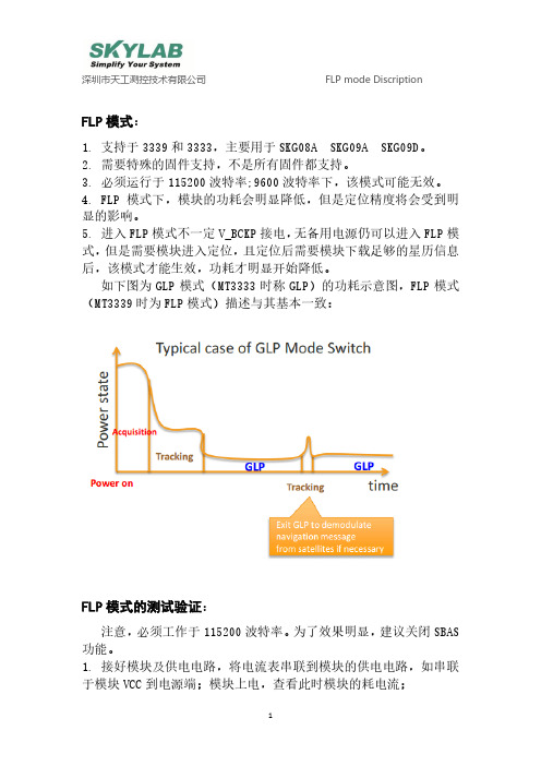
FLP模式:1. 支持于3339和3333,主要用于SKG08A SKG09A SKG09D。
2. 需要特殊的固件支持,不是所有固件都支持。
3. 必须运行于115200波特率;9600波特率下,该模式可能无效。
4. FLP模式下,模块的功耗会明显降低,但是定位精度将会受到明显的影响。
5. 进入FLP模式不一定V_BCKP接电,无备用电源仍可以进入FLP模式,但是需要模块进入定位,且定位后需要模块下载足够的星历信息后,该模式才能生效,功耗才明显开始降低。
如下图为GLP模式(MT3333时称GLP)的功耗示意图,FLP模式(MT3339时为FLP模式)描述与其基本一致:FLP模式的测试验证:注意,必须工作于115200波特率。
为了效果明显,建议关闭SBAS 功能。
1. 接好模块及供电电路,将电流表串联到模块的供电电路,如串联于模块VCC到电源端;模块上电,查看此时模块的耗电流;2. 关闭SBAS功能(指令$PMTK313,0*2F为关闭SBAS,打开SBAS功能的指令为$PMTK313,1*2E)且接好天线,建议天线放置于全开放天空环境下,保证良好收星;3. 等待模块进入定位,模块进入3D定位后至少再等1分钟,然后发送指令进入FLP模式($PMTK262,1*29使能FLP模式,$PMTK262,0*28关闭FLP模式)。
4. 等待模块下载足够的星历数据,有各个可见卫星的星历数据或者EPO数据,该过程需要5至30分钟,取决于信号情况。
5. 待模块收星完成,取得足够星历数据后,FLP模式会生效。
可见卫星个数和有效卫星个数应比较稳定,此时电流会周期性降低和升高。
对比此时的电流与未进入FLP模式前的电流。
降低时,加上有源天线的部分的耗电流,模块+天线整体的电流在7-11mA左右;升高时,模块+天线整体的耗电流在16-25mA左右。
6. FLP模式下,具体功耗和信号情况有关。
信号良好、稳定的情况下,功耗将更低。
GPS北斗定位模块用户手册.doc说明书
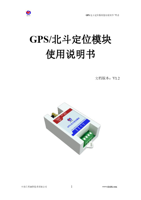
GPS/北斗定位模块使用说明书文档版本:V1.2目录1.产品介绍 (3)1.1产品概述 (3)1.2功能特点 (3)1.3设备技术参数 (3)1.4产品选型 (3)2.设备使用说明 (4)2.1设备安装前检查 (4)2.2接口定义 (4)3.配置软件安装及使用 (5)3.1软件选择 (5)4.通信协议 (6)4.1通讯基本参数 (6)4.2数据帧格式定义 (6)4.3寄存器地址 (7)4.4通讯协议示例以及解释 (8)4.4.1读取设备地址0x01的定位状态 (8)4.4.2读取设备地址0x01的经度 (8)4.4.3修改地址 (9)5.联系方式 (10)6.文档历史 (10)附录:壳体尺寸 (11)1.产品介绍1.1产品概述我公司研发生产的GPS/北斗定位模块,是一款具有GPS定位和北斗定位的双模定位终端,可以快速、有效、精确定位位置。
GPS/北斗定位模块内含双模定位芯片,可快速定位位置,并且将定位信息以RS232/485接口和ModBus协议的方式提供给用户使用,并可以通过PC 机设置软件或串口命令轻松控制,使用方便快捷。
1.2功能特点同时支持GPS定位和北斗定位(北斗二号和北斗三号1-63号全部卫星)采用WGS84世界大地坐标系,精准定位经纬度信息可实时读取对地速度、对地航向、海拔高度等信息串口波特率自定义,支持1200~115200bps模块串口波特率等参数可通过PC机或串口命令配置RS232/485带TVS、过流等保护提供天线状态诊断,提供天线开路、短路等状态信息1.3设备技术参数供电DC7~30V功耗0.348W使用环境工作温度-20℃~+60℃,0%RH~95%RH非结露通信接口RS232/485接口可选;通信波特率:1200~115200可设天线接口接我公司提供的GPS+北斗双频天线定位精度 2.5m(CEP50)海拔高度典型精度:±10m对地速度<0.36km/h(1σ)1.4产品选型RS-公司代号GPSBDS-GPS北斗定位模块N01-RS485(ModBus-RTU协议)N02-RS232(标准RS232-DB9接口)1GPS北斗定位模块外壳2.设备使用说明2.1设备安装前检查设备清单■GPS北斗定位模块1台■产品合格证、保修卡等■GPS+北斗双频天线安装尺寸:Φ2.5mm88mm2.2接口定义序号标识说明1DC10-30V电源输入设备供电10-30VDC宽压供电2Ant北斗+GPS双频天线3通信设备485通信灯4运行设备运行灯5电源正电源输出正6电源负电源输出负7485A通信:485-A8485B通信:485-B注:通信灯在设备485通信时亮0.1s,设备运行灯正常工作(定位成功)时亮0.5s,熄灭0.5s,异常(未定位成功)时亮0.1s,熄灭0.9s,且模块只需要一端供电就可以正常工作,另一端电源是为后级供电而准备,如不对后级进行供电,可悬空。
GPS模块使用说明

另外,模块自带了一个状态指示灯:PPS。该指示灯连接在UBLOX NEO-6M 模组的 TIMEPULSE端口,该端口的输出特性可以通过程序设置。PPS指示灯, 在默认条件下(没 经过程序设置),有2个状态: 1, 常亮,表示模块已开始工作,但还未实现定位。 2, 闪烁(100ms灭,900ms亮),表示模块已经定位成功。 这样,通过PPS指示灯,我们就可以很方便的判断模块的当前状态,方便 大家使用。
焊接 焊接
R2(1K) 不焊接
焊接 不焊接
焊接
使用协议 NMEA NMEA NMEA UBX
波特率 9600 38400 4800 57600
二、使用说明:
序号
1 2 3 4
名称 VCC TXD RXD GND
说明
电源(5V) 模块串口发送脚(TTL电平,不能直接接RS232电平!),可接单片机的RXD 模块串口接收脚(TTL电平,不能直接接RS232电平!),可接单片机的TXD 地
4,$GPRMC(推荐定位信息,Recommended Minimum Specific GPS/Transit Data)
$GPRMC语句的基本格式如下: $GPRMC,(1),(2),(3),(4),(5),(6),(7),(8),(9),(10),(11),(12)*hh(CR)(LF) (1) UTC时间,hhmmss(时分秒) (2) 定位状态,A=有效定位,V=无效定位 (3) 纬度ddmm.mmmmm(度分) (4) 纬度半球N(北半球)或S(南半球) (5) 经度dddmm.mmmmm(度分) (6) 经度半球E(东经)或W(西经) (7) 地面速率(000.0~999.9节) (8) 地面航向(000.0~359.9度,以真北方为参考基准) (9) UTC日期,ddmmyy(日月年) (10) 磁偏角(000.0~180.0度,前导位数不足则补0) (11) 磁偏角方向,E(东)或W(西) (12) 模式指示(A=自主定位,D=差分,E=估算,N=数据 无效) 举例如下: $GPRMC,023543.00,A,2308.28715,N,11322.09875,E,0.195,,240213,,,A*78
GPS模块使用说明

GPS模块使用说明一、模块简介该 GPS模块采纳瑞士 u-blox 公司的 NEO-5Q 主芯片 ,此芯片为多功能独立型GPS模组 ,以 ROM 为基础架构 ,成本低 ,体积小 ,并拥有众多特征。
采纳u-blox 最新的KickStart 轻微信号攫取技术 ,能保证采纳此模组的设备在任何可接收到信号的地点及任何天线尺寸都可以有最正确的初始定位性能并进行快速定位。
1.主要特征 :50个通道卫星接收功能100万个以上的相关系引擎可同步追踪 GPS及伽俐略导航卫星信号供给多种接口 :UART,USB,IIC,SPI2.性能参数 :接收器种类 : 50 个接收通道GPS L1 频率 ,C/A 码SBAS:WAAS,EGNOS,MSAS,GAGAN启动时间 : 冷启动 29 sec热启动 <1 sec辅助启动 <1 sec初次定位时间 :<1 sec最大更新速率 :<4Hz敏捷度 : 冷启动 -144dBm追踪敏捷度 -160dBm捕捉敏捷度 -160dBm定位精度 : Auto < 2.5mSBAS < 2m准时精度 : RMS 30ns99% <60ns极限速度 : 500m/s运转温度 : -40~85℃封装尺寸 : 16×12.2×2.4 mm3.电气性能 :工作电压 : 2.7V~3.6V功耗: 全速模式 135mW @ 3.0VECO 模式 129mW @ 3.0V备用电池 : 1.4V~3.6V,25uA4.接口协议 :串行接口 : 1 UART 1 USB V2.0 全速 12Mbit/s 1 IIC 1 SPI其余接口 : 1 时间脉冲输出1外面中断输入协议: NMEA,UBX 二进制二、硬件连接GPS模块接口图UART(TTL 电平 : 1.VCC-VCC 2.GND-GND 3.TXD-P3.0 4.RXD-P3.1 IIC: 5.SDA 6.SCLUART(232 电平 :9.VCC 10.GND 11.TXD 12.RXDSPI: 13.MOSI 14.MISO 15.SCK 16.CS接口说明 :1.模块和单片机连接只用到UART(TTL 电平接口。
ATK-NEO-6M GPS模块使用说明_AN1303
2013-03-10
ALIENTEK STM32开发板
AN1303
4, TFTLCD 模块
5, ATK-NEO-6M GPS 模块
接下来,我们看看 ATK-NEO-6M GPS 模块同 ALIENTEK STM32 开发板的连接,前面我们介
//buf:接收到的 GPS 数据缓冲区首地址
void NMEA_GPGSV_Analysis(nmea_msg *gpsx,u8 *buf)
{
u8 *p,*p1,dx;
u8 len,i,j,slx=0;
u8 posx;
p=buf;
p1=(u8*)strstr((const char *)p,"$GPGSV");
本文档分为如下几部分: 1, ATK-NEO-6M GPS 模块简介 2, 硬件连接 3, 软件实现 4, 验证
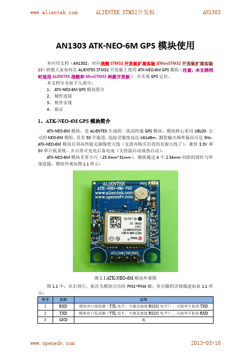
1、ATK-NEO-6M GPS 模块简介
ATK-NEO-6M 模块,是 ALIENTEK 生成的一款高性能 GPS 模块,模块核心采用 UBLOX 公 司的 NEO-6M 模组,具有 50 个通道,追踪灵敏度高达-161dBm,测量输出频率最高可达 5Hz。 ATK-NEO-6M 模块自带高性能无源陶瓷天线(无需再购买昂贵的有源天线了),兼容 3.3V 和 5V 单片机系统,并自带可充电后备电池(支持温启动或热启动)。
}
}
//分析 GPGGA 信息
//gpsx:nmea 信息结构体
//buf:接收到的 GPS 数据缓冲区首地址
2013-03-10
ALIENTEK STM32开发板
GPS模块使用说明

GPS模块使用说明
GPS模块样品图
1 GPS模块配件清单:
配件名称数量
GPS模块主板1块
GPS天线1条
串口通信线1条
2 硬件接口说明:
3 硬件连接方法
首先要连接好GPS天线,将天线接收端放在开阔的户外,因为室内信号弱甚至没有信号不利于进行测试。
确保天线周围没有高大的建筑物阻挡,以便能容易就收到卫星信号。
连接GPS天线
和计算机连接
1. 将串口通信线的4pin插头和GPS模块的4pin插口连接好,连接时将通信线4pin插头有两条突起的一面朝GPS内插入,如图所示:
2. 用串口通信线的另一头与计算机连接。
即将串口通信线的端插入到
计算机的(红线所圈处)。
3. 打开U-center软件。
4. 将5V直流电源与串口通信线九针插口端的两根电源线(如下图红线所圈处,红线代表正极,黑色代表负极。
)接好(红线与红线相接,黑线与黑线相接)。
然后将5V电源通上电,GPS模块主板上电源指示灯会亮起,数据指示灯不停的闪烁,表示GPS模块正在通过串口发送数据(GPS模块正常工作状态下,是有两个等常亮一个灯闪烁或一个灯常亮一个灯闪烁)。
GPS模块使用介绍说明
GPS模块使用手册一、GPS模块的几个重要指标1.卫星轨迹全球有24颗GPS卫星沿6条轨道绕地球运行(每4个一组),GPS接收模块就是靠接收这些卫星来进行定位的。
但一般在地球的同一边不会超过12颗卫星,所以一般选择可以跟踪12颗卫星以下的器件就可以了。
当然,所能跟踪的卫星数越多,性能越好。
大多数GPS 接收器可以追踪8~12颗卫星。
计算2维坐标至少需要3颗卫星,4颗卫星可以计算3维坐标。
2.并行通道由于最多可能有12颗卫星是可见的,GPS接收器必须按顺序访问每一颗卫星来获取每颗卫星的信息,所以市面上的GPS接收器大多数是12并行通道型的,这允许它们连续追踪每一颗卫星的信息。
12通道接收器的优点包括快速冷启动和初始化卫星的信息,而且在森林地区可以有更好的接收效果。
一般12通道接收器不需要外置天线,除非是在封闭的空间,如船舱或车厢中。
3.定位时间定位时间是指重启GPS接收器时,确定现在位置所需的时间。
对于12通道接收器,冷启动时的定位时间一般为3~5 min,热启动时为15~30 s。
4.定位精度普通GPS接收器的水平位置定位精度在5~10 m内。
5.DGPS功能DGPS是一个固定的GPS接收器,用于接收卫星的信号。
DGPS可以准确地计算出理论上卫星信号传送到的精确时间,然后将它与实际传送时间相比较,并计算出差值。
DGPS将这个差值发送出去,其它GPS接收器就可以利用这个差值得到一个更精确的位置读数(5~10 m或者更少的误差)。
许多GPS设备提供商在一些地区设置了DGPS发送机,供客户免费使用,只要客户所购买的GPS接收器有DGPS功能即可。
6.信号干扰要获得一个很好的定位信号,GPS接收器必须至少能接收到3~5颗卫星。
如果是在峡谷中或两边高楼林立的街道上,或者是在茂密的丛林里,有可能接收不到足够的卫星,无法定位或者只能得到二维坐标。
同样,如果在一个建筑里面,有可能无法更新位置。
一些GPS 接收器有单独的天线可以贴在挡风玻璃上,或者将一个外置天线放在车顶上,这有助于接收器收到更多的卫星信号。
CC50-BG 北斗二 GPS卫星导航模块使用说明书
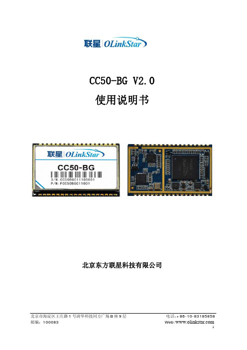
1.2 系统框图
图 1 CC50-BG 模块外观
1PPS
USB UART0 UART1
SDRAM BB
Flash
ProGee II
IF RF Process
Ref CLK
LNA SAW Filter
TCXO
3.0Vant
Antenna RF_IN
VDDRTC
Power Management
VDDin PWR_CTRL
和 PWR_DWN_n,分别可以关闭模块电源以及将模块设置为低功耗模式。模块内部在两个引 脚上有上拉电阻。
1.3.6 RTC 电源:CC50-BG 提供一个外部 RTC 电源输入,并可以通过该引脚对外接的可充电电
池或法拉电容充电,充电电压为 2.85V。
1.4 性能指标
参数
GNSS 性能
频率
通道数
首次定位 时间
CC50-BG V2.0 使用说明书
北京东方联星科技有限公司
北京市海淀区王庄路 1 号清华科技同方广场 B 座 9 层 邮编:100083
电话:+86-10-83185858
Web:
1
目录
1 功能描述...................................................................................................................................... 3 1.1 产品概述............................................................................................................................... 3 1.2 系统框图............................................................................................................................... 3 1.3 输入输出接口....................................................................................................................... 4 1.4 性能指标............................................................................................................................... 4 1.5 机械特性............................................................................................................................... 6 1.6 引脚定义............................................................................................................................... 7 1.7 电气特性............................................................................................................................... 9
OBT2217 GPS BD双模模块使用说明书

OBT2217GPS/BD 双模模块使用说明书版本:V2.0珠海欧比特控制工程股份有限公司广东省珠海市唐家东岸白沙路1号欧比特科技园(邮编: 519080)电话: ************传真*************声明珠海欧比特拥有此非公开出版的使用说明书的版权,并有权将其作为保密资料处理。
本使用说明书只作为操作、保养和维修产品的参考资料,其他人无权向他人公开此使用说明书。
本使用说明书包含由版权法保护的专有资料,版权所有,未经珠海欧比特的书面同意不得将本使用说明书的任何部分进行照相复制,复印或翻译成其它语言。
本使用说明书包含的内容可以不予通知而有所变更。
制造商的责任只有在下列情况下,珠海欧比特才认为应对模块的安全、可靠性和性能的有关问题负责:装配、扩充、重新调整、改进或维修均由公司认可的人员进行操作;设备的使用按操作要求进行。
目 录1.功能描述 (1)1.1.概述 (1)1.2.产品特性 (1)1.3.性能指标 (2)1.4.应用 (2)1.5.功能框图和典型应用 (3)1.5.1功能框图 (3)1.5.2 典型应用 (3)2.模块接口说明 (4)2.1.硬件接口 (4)2.1.1 电源 (4)2.1.2 天线接口 (4)2.1.3 1PPS 信号接口 (4)2.1.4 UART 接口 (5)2.1.5 GPIO 接口 (5)2.2.软件接口协议 (5)2.2.1 语句格式和内容 (5)2.2.2 输出语句 (6)2.2.3 输入语句 (7)3.机械特性 (9)3.1.模块尺寸 (9)3.2.管脚定义 (10)4.电气和温度特性 (12)4.1.模块直流特性 (12)4.1.1 极限工作条件 (12)4.1.2 推荐工作条件 (13)4.2.焊接温度曲线 (13)5.注意事项 (14)5.1.静电防护 (14)5.2.PCB设计建议 (14)5.3.模块软件升级 (15)5.4.其他 (15)附录A:订货信息 (16)附录B:装箱单 (16)1.功能描述1.1. 概述OBT 2217 BD/GPS模块是支持BD2 (B1)和GPS L1的高性能集成模块,此模块内部集成了BD2 B1/GPS L1双模SOC基带芯片和双模射频芯片,为车载、船载和便携式手持等导航定位终端产品的制造提供了高灵敏度、低功耗、低成本的BD2B1/GPS L1双模解决方案。
NEO-6M-GPS模块说明手册

UBLOX-6M-GPS模块说明手册UBLOX-6M-GPS模块说明手册 (1)一.模块介绍 (2)二、模块参数 (2)1.电压 (2)2.温度 (2)3.引脚说明以及电气连接 (2)4.波特率 (3)5.特性参数 (3)三、模块尺寸 (4)四、模块调试和GPS数据解析 (5)一.模块介绍BLOX6M GPS模块,具有高灵敏度、低功耗、小型化、其极高追踪灵敏度大大扩大了其定位的覆盖面,在普通GPS接收模块不能定位的地方,如狭窄都市天空下、密集的丛林环境,UBLOX6M都能高精度定位。
模块的高灵敏度、小静态漂移、低功耗及轻巧的体积,非常适用于车载、手持设备如PDA,车辆监控、手机、摄像机及其他移动定位系统的应用,是GPS产品应用的最佳选择。
二、模块参数1.电压输入电压: 3.3-5.5V功耗正常模式:50mA省电模式:30mA2.温度工作温度-40°Cto+85°C存储温度-55°Cto+100°C3.引脚说明以及电气连接模块引脚1VCC电源脚输入3.3-5.5V2GND电源地3RXD模块串口接收脚--接单片机串口TXD发送4TXD模块串口发送脚--接单片机串口RXD接收5PPS时钟脉冲输出脚模块PPS脚接了红色LED灯常亮:正常工作,但未定位闪烁:定位成功4.波特率模块默认的波特率是96005.特性参数模块自带陶瓷天线,另外有IPEX接口可以连接其他有源天线模块增加了射频放大电路,有利于加快搜星模块自带可充电后备电池,可以掉电保持星历数据模块兼容3.3V/5V电平,方便连接各种单片机系统三、模块尺寸长宽:37.4x26.2四、模块调试和GPS数据解析1.首先用一条microusb线将模块和电脑连接,然后找到资料里面的usb驱动文件,安装完毕后在设备管理器会看到如下图所示,出现一个虚拟串口2.打开资料里面的多功能调试助手,选择gps定位3.定位必须在室外空旷地进行,否则无法定位成功,陶瓷天线面向天空。
- 1、下载文档前请自行甄别文档内容的完整性,平台不提供额外的编辑、内容补充、找答案等附加服务。
- 2、"仅部分预览"的文档,不可在线预览部分如存在完整性等问题,可反馈申请退款(可完整预览的文档不适用该条件!)。
- 3、如文档侵犯您的权益,请联系客服反馈,我们会尽快为您处理(人工客服工作时间:9:00-18:30)。
GPS模块使用说明
一、模块简介
该GPS模块采用瑞士u-blox公司的 NEO-5Q主芯片,此芯片为多功能独立型GPS模组,以ROM为基础架构,成本低,体积小,并具有众多特性。
采用u-blox 最新的KickStart微弱信号攫取技术,能确保采用此模组的设备在任何可接收到信号的位置及任何天线尺寸都能够有最佳的初始定位性能并进行快速定位。
1. 主要特性:
50个通道卫星接收功能
100万个以上的相关系引擎
可同步追踪GPS及伽俐略导航卫星信号
提供多种接口:UART,USB,IIC,SPI
2. 性能参数:
接收器类型: 50个接收通道
GPS L1频率,C/A码
SBAS:WAAS,EGNOS,MSAS,GAGAN
启动时间: 冷启动 29 sec
热启动 <1 sec
辅助启动 <1 sec
首次定位时间:<1 sec
最大更新速率:<4Hz
灵敏度: 冷启动 -144dBm
跟踪灵敏度 -160dBm
捕获灵敏度 -160dBm
定位精度: Auto < 2.5m
SBAS < 2m
定时精度: RMS 30ns
99% <60ns
极限速度: 500m/s
运行温度: -40~85℃
封装尺寸: 16 × 12.2 × 2.4 mm
3. 电气性能:
工作电压: 2.7V~3.6V
功 耗: 全速模式 135mW @ 3.0V
ECO 模式 129mW @ 3.0V
备用电池: 1.4V~3.6V,25uA
4. 接口协议:
串行接口: 1 UART 1 USB V2.0 全速12Mbit/s
1 IIC 1 SPI
其他接口: 1 时间脉冲输出
1 外部中断输入
协 议: NMEA,UBX二进制
二、硬件连接
GPS模块接口图
UART(TTL电平): 1.VCC-VCC 2.GND-GND 3.TXD-P3.0 4.RXD-P3.1 IIC: 5.SDA 6.SCL
UART(232电平):9.VCC 10.GND 11.TXD 12.RXD
SPI: 13.MOSI 14.MISO 15.SCK 16.CS
接口说明:
1.模块和单片机连接只用到UART(TTL电平)接口。
2.UART(232电平)接口可直接和电脑串口相连,用户可自己设计电路。
3.板上留有USB 2.0接口(J4),用户如需要,可自己焊接(芯片为
USBLC6-2SC6)。
4.板上留有ARM接口(J3),可以和TX-2440A开发板相连。
5.SPI和IIC接口一般很少用到。
注:由于部分接口没有用到,所以在电路板上有部分元件没有焊接,如果用 户需要,请对照原理图焊接相关元件。
在电路板背面留有备用电池焊盘,如果需要用备用电池,可自己焊接。
三、操作步骤:(例程使用51单片机和12864LCD)
1.将GPS模块的天线连接好,天线接收端要放在开阔的户外,因为室
内没有信号。
2.连接好12864LCD,可根据自己的连线方式修改程序的LCD控制引脚,
引脚定义在LCD.h中。
TX-1C和51STAR的LCD引脚定义相同。
3.将例程(GPS test.hex)下载到单片机中,注意一定要先下程序,再
连接模块,因为模块占用P3.0和P3.1口,下载程序时会有冲突。
4.用杜邦线将模块和单片机连接,连接方式见硬件连接图。
如果使用
51STAR实验箱,可直接将模块插在MP3模块的插座上。
5.打开电源,屏幕会显示初始化信息,观察第一个发光二极管,如果闪
烁,说明GPS连接正确,正在接收数据,见图1。
如果发光二极管不
闪烁,请检查模块连接。
6.等待一段时间,收到有效数据后,第二、三个发光二极管会点亮,屏
幕上会显示当前日期和时间,所在位置的经度纬度,见图2;5秒后,
屏幕刷新,显示速度,航向,高度,海拔高度,见图3;每隔5秒钟,
更换显示。
7.如果想查看GPS接收的数据包格式,可将GPS和电脑串口相连,用串
口调试助手查看。
模块上增加了232电平转换电路,引脚为:9~12,
连接好串口后(注意要共地),接通电源,打开串口调试助手,就可
以看到接收到的数据了,见图4。
图1
图2
图3
图4
四、注意事项
1.天线必须延伸到室外开阔处,以便接收到信号。
2.如果使用TX-1C开发板USB供电,LCD的亮度不够,显示不清楚,最
好使用外部直流电源供电,以便给LCD提供较大的电流。
3.每次下载程序之前,先拔下GPS模块,下载完程序后再插上模块。
4.由于GPS冷启动需要一些时间,刚开始收到的数据都是无效的,收
到有效数据后,屏幕上显示GPS信息。
根据情况,一般在开机后30
秒到1分钟内,数据才会有效。
如果长时间接收不到有效数据,请
检查天线,确保天线在室外,并且没有高大建筑物阻挡信号。
5.静止时测得的速度和航向都是不准确的,当朝某个方向运行达到一
定速度时,才会测得准确数据。
6.接收到有效数据后,过一段时间屏幕可能又会显示初始化状态,是
因为暂时的信号中断,等待一会,信号就会正常
五、实物连接展示(与TX-1C开发板连接)
GPS初始化
第一屏
第二屏。
