6360安装手册
6360_6330说明书

防高温 ................................................................................................... 11 防腐蚀 ................................................................................................... 11
使用说明书
MC-6360 MC-6330
编辑及出版说明
本说明书在北京铭创科技有限公司监督下编辑出版,包含最新的产品说明和规格。 本说明书及内容及产品规格如有更改,恕不另行通知。 北京铭创科技有限公司保留对包含在说明书中的产品规格和内容做出更改的权利, 恕不另 行通知,同时由于使用本说明书所包含的内容所造成的任何损坏(包括后果) ,包括但不 仅限于本出版物的排版及其他错误,北京铭创科技有限公司将不承担任何责任。
内置锂电池 ........................................................................................... 12 径向换能器 ........................................................................................... 12 仪器主机保.................................................. 12 责 任 ........................................................................................................... 14
FANUC数控资料文库
B-64134EN/01 B-64144EN/01 B-64154EN/01 B-64160EN/01 B-63944CM/02 B-63944CM-1/02 B-63944CM-2/02 B-63945CM/02 B-63950CM/02
B-63944EN/02 Add_info B-63944EN-1/02 B-63944EN-2/02 Add_info B-63944EN-2/02 B-63945EN/02 Add_info B-63945EN/02 B-63950EN/02 Add_info B-63950EN/02 B-63944JA/02 追加資料 B-63944JA/02 B-63944JA-1/02 追加資料 B-63944JA-1/02 B-63944JA-2/02
FANUC B-64310CM-01 参数说明书 FANUC FANUC 0i-MD 规格一览表 FANUC FANUC 0i-D系列多语言显示功能 FANUC 0i-D新产品说明 FANUC B-62760CT-01 16 18-C 参数手册 FANUC B-63524CM-01 16i 18i-TB 操作说明书 FANUC B-63525CM-02 16i 18i 21i-B 维修说明书 FANUC B-63530CM-02 16i 18i-B 参数说明书 FANUC B-63534CM-02 16i 18i-MB操作说明书 FANUC B-63604CM-01 21i-TB 操作说明书 FANUC B-63610CM-01 21i-B参数说明书 FANUC B-63614CM-01 21i 21Oi-MB 操作说明书 FANUC B-63524EN-01 16i 18i-TB 操作说明书 FANUC B-63525E-02 16i 18i 21i-B 维修手册 FANUC B-63664EN-02 16i-LB操作说明书 FANUC B-63665EN-01 16i-LB维修说明书 FANUC B-63665EN-02 16i 18i-LB维修说明书 FANUC B-63684EN-01 16i 18i-PB操作说明书 FANUC B-63690EN-01 16i 18i-PB参数说明书 FANUC B-64113C-1-01 0i-C Mate-C连接说明书(功能) FANUC B-64113C-01 0i-C Mate-C连接说明书(硬件) FANUC B-64114CM-01 0i-TC操作说明书 FANUC B-64115CM-02 0i-C Mate-C维修说明书 FANUC B-64120CM-01 0i-C Mate-C参数说明书 FANUC B-64124CM-01 0i-MC操作说明书 FANUC B-64134CM-01 0i Mate-TC操作说明书 FANUC B-64144CM-01 0i Mate-MC操作说明书 FANUC B-64114EN-01 0i-TC操作说明书 FANUC Add_info B-64114EN-01 0i-TC操作说明书补充 资料 FANUC B-64124EN-01 0i-MC操作说明书 FANUC Add_info B-64124EN-01 0i-MC操作说明书补充 资料 FANUC B-64115EN-03 0i-C Mate-C维修说明书 FANUC B-64120EN-02 0i-C Mate-C参数说明书
6360E基本知识(精装版)
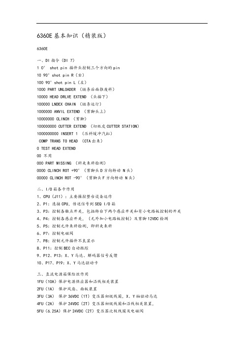
6360E基本知识(精装版)6360E一、DI指令(DI 7)1 0° shot pin 插件头控制三个方向的pin10 90°shot pin R(右)100 90°shot pin L(左)1000 PART UNLOADER (链条后面推废料)10000 HEAD DRLVE EXTEND (头插下)100000 LNDEX CHAIN (链条运行)1000000 ANVIL EXTEND (剪脚头上)10000000 CLINCH (剪脚)100000000 CUTTER EXTEND (切纸皮CUTTER STATION)1000000000 INSERT 1 (压料缓冲汽缸)COMP TRANS TO HEAD (CTA出来)0 TEST HEAD EXTEND00 不用000 PART MISSING (料夹来料检测)0000 CLINCH ROT +90°(剪脚头D方向转动 N头)00000 CLINCH ROT -90°(剪脚头F方向转动 N头)二、I/O箱各卡作用1、CPU(J11):主要操控整台设备运作2、P1:连接CPU,传送信号到SEQ I/O箱3、P3:控制各触点开关,包括转台下两个感应开关和有小电路板控制的开关4、P4:控制各感应开关,(无外加小电路板控制)及剪脚12VDC检测5、P5:控制元件来料检测,即料夹来料6、P7:控制电磁阀7、P8:控制元件插件不良显示8、P11:控制BEC自动跟踪9、P12、P13:X、Y马达、解码器信号反馈10、P17、P19:X、Y马达驱动卡三、直流电源箱保险丝作用1FU(10A)保护电源供应器和沿线相关装置2FU(1A)保护风扇、面板装置3FU(3A)保护36VDC(1T)变压器初级线圈,X、Y轴驱动马达4FU(2A)保护24VDC(2T)变压器初级线圈和沿线相关装置,5FU(6.25A)保护24VDC(2T)变压器次极线圈及电磁阀6FU(3A)保护12VDC工作灯7FU(3A)保护12VAC安全继电器8FU(0.25A)保护外部设备急停电路四、编序机电源箱保险丝作用11FU(10A)保护编序机的主电源系统12FU(1A)保护风扇电源13FU(3A)保护用来产生66VDC的变压器初级(链条)14FU(6.25A)保护24VAC电源变压器(14T)和电磁阀15FU(0.5A)没用16FU(6.25A)保护从24VAC电源到主电磁阀的线路17FU(8A)保护分配头1-2018FU(8A)保护分配头21-4019FU(8A)保护分配头41-6020FU(8A)保护分配头61-8021FU(8A)没用22FU(4A)保护编序机伺服放大卡(链条卡死也会烧此保险丝)五、各组电压作用1、+5VDC 用在CPU、解码器、发光二极管2、+12VDC 用在工作灯、操作面板灯3、±15VDC用在CPU4、+36VDC 用在X、Y轴马达5、24VAC 用在24VAC继电器、电磁阀(8AC信号板)6、6.75VDC六、解码器的作用▲把普通文解码为电文工作原理:当普通信号由CPU给出指令到P12、P13伺服卡,由伺服卡传送到解码器,再由解码器译成适合马达运作的电信号,并控制马达七、各调整参数1、N头:CUTTER与ANVIL:1/2距离2、T头:CUTTER FORMER与ANVIL:0.069±0.001inch(在无工作条件下)CUTTER FORMER与CUTTER FORMER:0.247inch(6.27mm±0.05)(在工作条件下)CUTTER FORMER与ANVIL(剪三极管):0.020inchANVIL与LNSULATED ECCENTRICS(绝缘偏心检测棒):0.003-0.005inchCLINCH感应磁铁位置:0.38inch(9.6mm)3、插件头与CTA(在工作条件下)固定插件刀三角块起来时离面盖:0.005inchCTA的TOP GUIDE与插件刀:0.008-0.010inchCTA的BOTTOM GUIDE与插件刀:0.008-0.010inchCTA的BOTTOM GUIDE与LATCH:0.020inchTOP与料夹:0.030inch4、分配头推料刀与料夹:0.030inch5、CUTTER STATION(切纸皮)冲程:0.005inch八、链条力调整(简单步骤)1、确定力弹簧:2inch2、手动推BLOCK(白色四方块),将弹簧压至1.75inch3、调整BLOCK中间螺丝,压缩弹簧至1inch4、检查后面是否1-1.5inch(用两把直尺垂直,一把与装料夹中间的柱子中线,另一把与料夹成90度九、链条速度调整▲选100个料夹,在第1个料夹夹一料,第100个夹一料。
Moxa NPort S8000系列快速安装指南说明书

P/N: 1802080000018*1802080000018*NPort S8000 Series Quick Installation GuideVersion 7.1, January 2021Technical Support Contact Information/support2021 Moxa Inc. All rights reserved.OverviewThe Moxa NPort S8000 Series fully integrates an industrial serial device server and redundant managed Ethernet switch into a single device, making it easy to enable your serial devices to operate over a network and connect Ethernet-enabled devices in industrial field applications. Package ChecklistBefore installing the NPort S8000, verify that the package contains the following items:• 1 NPort S8000 combo switch / serial device server•CBL-RJ45F9-150 cable•Quick installation guide•Warranty cardOptional Accessories (must be ordered separately)•Wall-mounting kitPlease notify your sales representative if any of the above items are missing or damaged.Hardware IntroductionThe NPort S8455I integrates 5 Ethernet ports and 4 male DB9 ports for the RS-232/422/485 serial port.NPort S8455I-SS-SC/NPort S8455I-MM-SC integrates 2 fiber ports, 3 Ethernet ports, and 4 male DB9 ports for the RS-232/422/485 serial port.The NPort S8458 integrates 4 fiber ports, 4 Ethernet ports, and 4 male DB9 ports for the RS-232/422/485 serial port.Reset Button—Hold the Reset button for 5 seconds to load factory default settings: Use a pointed object, such as a straightened paper clip or toothpick, to press the reset button. This will cause the Ready LED to blink on and off. The factory defaults will be loaded once the Ready LED stops blinking (after about 5 seconds). At this point, you should release the reset button.LED Indicators—The NPort S8000’s front panel contains some LED indicators as described in the following table.Type Color MeaningPW 1 Green Power 1 inputPW 2 Green Power 2 inputReady Red Steady On: Power is on, and the NPort isbooting up.Blinking: Indicates a LAN-IP conflict, or theDHCP or BOOTP server did not respondproperly.Green Steady On: Power is on, and the NPort isfunctioning normally.Blinking: The device server has been locatedby the Administrator’s location function.Off Power is off, or power error condition exists. Master Green When the NPort is the Master of this TurboRing.Blinking When the NPort is the Ring Master of thisTurbo Ring and the Turbo Ring isdisconnected.Coupler Green When the NPort enables the coupling functionto form a backup pathSerial Port TX Green The serial port is transmitting data.Serial Port RX Amber The serial port is receiving data.Link (FX) Green The FX port’s 100 Mbps is activeBlinking Data is being transmitted/received at 100MbpsLink Green The 100 Mbps Ethernet connection is active.Amber The 10 Mbps Ethernet connection is active. Hardware Installation ProcedureSTEP 1: Remove the NPort S8000 from the box.STEP 2: Use a standard straight-through Ethernet cable to connect to a hub or switch. When setting up or testing the NPort S8000, you might find it convenient to connect directly to your computer’s Ethernet port. In this case, use a crossover Ethernet cable.STEP 3: Connect the NPort S8000’s serial port to a serial device. STEP 4: Connect the power source to the NPort S8000 and power it up for configuring or testing.STEP 5: Mount the NPort S8000 to either a wall or DIN-rail, as described below.Wall Mounting (optional)In high-vibration environments, we suggest using the NPort S8000’s wall-mount kit to fix. The installation procedure is described below:STEP 1: Remove the aluminum DIN-rail attachment plate from the NPort S8000’s rear panel and then attach the wall-mount plates with M3 screws.STEP 2: Four screws are required. Use the NPortS8000, with wall-mount plates attached, as a guide tomark the correct locations of the 4 screws. The headsof the screws should be less than 6.0 mm in diameter,and the shafts should be less than 3.5 mm in diameter.NOTE Before tightening the screws into the wall, make sure the screw head and shank sizes are suitable by inserting one of the screws into one of the keyhole-shaped openings of the wall-mountingplates.Do not screw the screws in completely—leave about 2 mm to allow room for sliding the wall-mount panel between the wall and the screws.STEP 3: Once the screws are fixed to the wall, insert the four screw heads through the large parts of the keyhole-shaped openings and slide the NPort S8000 downwards as indicated. Tighten the four screws for added stability.DIN-rail Mounting (optional)DIN-rail attachments can be purchased separately toattach the product to a DIN-rail. When snapping theattachments to the DIN-rail, make sure that the stiffmetal springs are at the top.Turbo Ring DIP Switch SettingsThe default setting for each DIP switch is OFF. The followingtable explains the effect of setting the DIP switch to the ONposition.Turbo Ring SettingsDIP DIP 1 DIP 2 DIP 3 DIP 4– Ring Master Ring CouplingportEnable DIP1, 2, 3ON – Enable Enable Activates Default OFF – Disable Disable Disabled Turbo Ring V2 SettingsDIP DIP 1 DIP 2 DIP 3 DIP 4 Ring Coupling Ring MasterRing CouplingportEnable DIP1, 2, 3ON Backup portEnableEnable Enable ActivatesDefault OFF Primary portEnableDisable Disable Disabled.Software Installation InformationFor the NPort’s configuration, the default IP address of the NPort is: LAN: Static IP = 192.168.127.254; netmask = 255.255.255.0You may log in with the account name admin and password moxa to change any settings to meet your network topology (e.g., IP address) or serial device (e.g., serial parameters). You may also refer to Moxa support website https:///support for user’s manual, driver, SNMP MIB, and NPort Search Utility.NOTE For NPort with DB Male serial ports, you may refer to the DB9 Male Ports pin assignment section to loop back pin 2 and pin 3 forthe RS-232 interface to carry out a self test on the device.Pin Assignments and Cable WiringDB9 Male Port PinoutsPin RS-232RS-422/RS-485-4wRS-485-2w1 DCD TxD-(A) –2 RxD TxD+(B) –3 TxD RxD+(B) Data+(B)4 DTR RxD-(A) Data-(A)5 GND GND GND6 DSR – –7 RTS – –8 CTS – –9 – – –Wiring the Relay ContactThe NPort S8000 has two sets of relay outputs: relay 1 and relay 2. Each relay contact consists of two contacts of the terminal block on the NPort S8000’s top panel. Refer to the next section for detailed instructions on how to connect the wires to the terminal block connector and how to attach the terminal block connector to the terminal block receptor. The two contacts used to connect the relay contacts work as follows (see illustration below):The fault circuit will open if1. A relay warning event is triggered, OR2. The NPort S8000 is the Master of this Turbo Ring,and the Turbo Ring is disconnected, OR3. Start-up fails.If none of these three conditions are met, the fault circuit will remain closed. Wiring the Digital InputsThe NPort S8000 unit has two sets of digital inputs: DI 1 and DI 2. Each DI consists of two contacts of the 6-pin terminal block connector on the NPort S8000’s top panel. The remaining contacts are used for the NPort S8000’s two DC inputs. The top and front views of one of the terminal block connectors are shown below.Take the following steps to wire the digital inputs:1. Insert the negative (ground) or positive DI wiresinto the terminals.2. To keep the DI wires from getting loose, use asmall flat-blade screwdriver to tighten thewire-clamp screws on the front of the terminalblock connector.3. Insert the plastic terminal block connectorprongs into the terminal block receptor, which islocated on the NPort 8000’s top panel. Wiring the Dual Power InputsThe NPort S8000 unit has two sets of power inputs: power input 1 and power input 2. The top two contacts and the bottom two contacts of the 6-pin terminal block connector on the top panel are used for the NPort S8000’s two power inputs. The top and front views of one of the terminal block connectors are shown below.Take the following steps to wire the redundant power inputs:1. Insert the negative/positive DC wires into the V-/V+ terminals.2. To keep the DC wires from pulling loose, use a small flat-bladescrewdriver to tighten the wire-clamp screws on the front of the terminal block connector.3. Insert the plastic terminal block connector prongs into the terminalblock receptor, which is located on the NPort S8000’s top panel.NOTE Complies with 21 CFR 1040.10 and 1040.11 except for conformance with IEC 60825-1 Ed. 3, as described in LaserNotice No. 56, dated May 8, 2019.NOTE When wiring the Terminal Block inputs, please use copper conductors only, with rated 300 V/15 A, solder on the board,compatible with a plug-half connector suitable for 28-12 AWG(Sol, Str) wire size, torque value 4.5 lb-in.NOTE These devices are open-type devices that are to be installed in an enclosure only accessible with the use of a tool, suitable for theenvironment.NOTE This equipment is suitable for use in Class I, Division 2, Groups A, B, C, and D or nonhazardous locations only.。
防盗报警设备技术参数
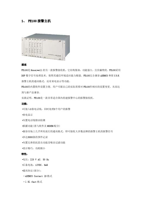
1、 FE100接警主机描述FE100是Honeywell的另一款报警接收机,它结构紧凑,功能强大,且价廉物美。
FE100采用DSP数字信号处理技术,使得其通信环境适应能力极强。
FE100完全兼容ADEMCO和原C&K 报警主机的通讯格式,还有来电显示等功能。
FE100的内置软件设置方便,用户可据自己的实际需要对FE100作相应的设置变更,从而达到与新产品兼容。
实践证明,FE100是一款非常适合国内组建报警中心的报警接收机。
功能:▪可接入8条电话线,同时处理8个用户的报警▪来电显示▪内置电话线错误检测▪抓擢功能(需与软件及MODEM配合)▪兼容市场上几乎所有流行的通讯格式,即可接收大多数品牌的报警主机的报警信号▪多达5000条的事件记录▪内置完善的抗雷击功能及噪音过滤功能▪设计精巧,功耗极小特性:▪电压:220 V AC,50 Hz▪后备电池:12VDC,6AH▪通讯协议(部分):·ADEMCO Contact lD格式·l El fast格式·4+2(1400Hz)格式·4+2(2300Hz)格式·C&K格式·C&K(bell)格式输出:·TerminaI(终端)·打印机·RS-232尺寸:400X200X353mm2、 Monitor XP 7.0 标准版Monitor XP7.0监察者系列报警中心管理软件是北京迈特安技术发展有限公司最新开发的新一代联网报警中心管理软件。
经过了近十年的积累和完善,已经被广泛应用于传统的公用电话网(PSTN)联网报警中心和新型的网络化联网报警中心。
目前已有包括专业保安公司、公安、部队、金融、通信等行业在内的数千家不同规模的报警中心在应用Monitor XP软件,在行业相关产品的市场占有率为80%以上,成为各保安协会推荐的以及各报警中心建设、改造的首选专业软件。
功能特点:➢可容纳上千用户入网➢全面兼容CFSK III、Contact ID、4+2 Express等协议➢支持多种联网方式➢支持多种接警设备➢数据库稳定可靠➢二次开发方便➢操作员分级管理➢操作简单直观➢声光电报警提示➢详尽的报告查询与统计➢用户设置报告触发功能➢全局和多级电子地图功能➢多级联网报警转发功能➢预置处警预案功能➢单据管理功能➢报表统计功能➢资料导出功能➢计划任务功能➢事件查询功能➢来电显示功能➢遥控编程功能➢视频复核功能➢短信转发功能3、236 报警主机描述新增功能:Contact ID信息格式支持4个报警接收机实时时钟电话线检测钥匙布撤防自动恢复出厂设定值通讯失败重拨时间和最大重拨次数可编程外部继电器驱动支持15个用户密码AC掉电检测时间可编程(5,10,15分钟)防区特性:6个基本防区,均具备末端电阻监控功能,提高系统防破坏能力键盘自带紧急按键软防区和防劫持操作,提供更多的安全保障防区回路的电路类型可编程选择,适应不同的防区要求和传感器性能防区保留产品手册P34三个产品图反应时间可编程选择,与不同探测器的性能更好地匹配,避免干扰误报控制特性:支持1个系统主密码和14个用户密码防拆保护可以使用LED或ALPHA(LCD)键盘对系统进行控制,也可通过接警中心远程遥控可以通过钥匙开关对系统进行布撤防,方便老人小孩使用10种不同事件驱动外部继电器输出,可编程设定驱动方式,应用灵活方便大灵活的联网功能,可同时支持4个接警中心双重、分类或后备报告方式可选内置看门狗复位电路,回复初始值功能,保证系统稳定工作内置电话线检测、AC掉电、后备电池、系统工作状态自检功能,报告周期可选电话线检测和AC掉电检测时间可调具备门铃功能,在撤防状态下,键盘显示实时时钟系统最多可接入8个键盘,其中LCD键盘不超过4个输出功能:键盘内置蜂鸣器,作为故障、报警等事件提示LED键盘具备系统及防区状态LED灯况提示,ALPHA键盘具备LCD字符信息显示2路触发器输出,驱动外部继电器内置拨号器,直接报告到接警中心接收机,重拨时间与轮次可编程。
环球VCD和SEQ调整
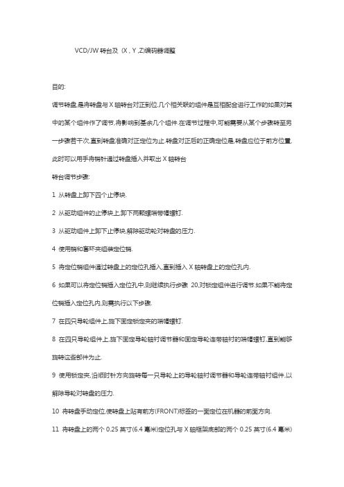
VCD/JW转台及(X , Y ,Z)编码器调整目的:调节转盘,是将转盘与X轴转台对正到位.几个相关联的组件是互相配合进行工作的如果对其中的某个组件作了调节,将影响到基余几个组件.在调节过程中,可能需要从某个步骤转至另一步骤若干次,直到转盘准确对正定位为止.转盘对正后的正确定位是,转盘应位于前方位置,此时可以用手将销针通过转盘插入并取出X轴转台转台调节步骤:1 从转盘上卸下四个止停块.2 从驱动组件的止停块上,卸下两颗螺端带帽螺钉.3 从驱动组件上卸下止停块,解除驱动轮对转盘的压力.4 使用销和套环夹组装定位销.5 将定位销组件通过转盘上的定位孔插入,直到插入X轴转盘上的定位孔内.6 如果可以将定位销插入定位孔中,则继续执行步骤20,对锁定组件进行调节.如果不能将定位销插入定位孔内,则需执行以下步骤.7 在四只导轮组件上,旋下固定锁定夹的端帽螺钉.8 在四只导轮组件上,旋下固定导轮轴衬调节器和固定导轮连带轴衬的端帽螺钉,直到能够旋转这些部件为止.9 使用锁定夹,沿顺时针方向旋转每一只导轮上的导轮轴衬调节器和导轮连带轴衬组件,以解除导轮对转盘的压力.10 将转盘手动定位,使转盘上贴有前方(FRONT)标签的一面定位在机器的前面方向.11 将转盘上的两个0.25英寸(6.4毫米)定位孔与X轴框架底部的两个0.25英寸(6.4毫米)定位孔对正到位.12 沿逆时针方向旋转,将所有导轮轴衬调节器预安装定位,除去转盘与导轮之间在垂直方向上的间隙.用手上下移动转盘,检查间隙是否已消除.13 在导轮已安装在X轴框架组件左前侧的情况下,进行以下操作.将导轮与转盘到正位,然后沿逆时针方向调节轴衬调节器.14 旋紧带帽螺丝钉,使其转矩介与40-45磅之间,在此状态下固定轴衬调节器.15 重复以上调节步骤13和14 ,将安装于X轴框架组件右后侧的导轮,调节至正确的转矩状态.16 对位于另一条对角线上的两只导轮,重复以上步骤13和14,完成整个调节.17 检查定位销组件.如果定位销不能顺利地滑入并取出定位孔,则说明已将轴衬调节器调节得过紧,支转盘的压力过大.18 将四颗止停块安装到转盘组件上.19 卸下固定开关架与锁定组件的螺钉,取下开关架.20 旋松固定锁定组件的带帽螺钉.21 将定位销插入定位孔中.22 用手移动锁定组件,直到定位销以均匀力度滑入对正孔内.23 以每次一个对角的形式,旋紧固定锁定组件的带帽螺钉,每颗螺钉旋紧1/8周,直到紧固所有的螺钉.24 取出定位销,从锁定组件上释放出止停块,然后旋转转盘,以便易地转盘止停块稳固地锁入锁定组件中.25 检查定位销,确保定位销能够顺利地滑入并取出定位孔。
FreeBSD完全安装手册—硬件需求

ep0 300 10 dyn dyn 3Com 3C509
ex0 dyn dyn dyn Intel EtherExpress Pro/10 cards
fe0 300 dyn Allied-Telesis AT1700, RE2000 and Fujitsu FMV-180 series cards.
mx0 dyn dyn dyn Macronix 98713/15/25 PCI based cards
pn0 dyn dyn dyn Lite-On PNIC PCI based cards
rl0 dyn dyn dyn RealTek 8129/8139 fast ethernet
uha0 330 dyn 6 dyn Ultrastore 14f
aha0 330 dyn 5 dyn Adaptec 154x SCSI controller
ahb0 dyn dyn dyn dyn Adaptec 174x SCSI controller
ahc0 dyn dyn dyn dyn Adaptec 274x/284x/294x SCSI controller
ze0 300 5 d8000 IBM/National Semiconductor PCMCIA Ethernet Controller
zp0 300 10 d8000 Com 3c589 Etherlink III PCMCIA Ethernet Controller
表中Device列是FreeBSD中对不同设备使用的不同设备名;Port列是设备使用的起始I/O地址,用16进制表示;IRQ列是设备所使用的中断号,用10进制表示;DMA列是设备所使用的DMA 通道号,用 10 进制表示;IOMEM 列是设备使用的起始内存地址,用 16 进制表示;最后一列是对硬件设备的描述。表中的 dyn 表示该项的具体值由系统内核( kernel )检测确定,空白处表示该设备不使用这个参数。
Moxa ioThinx 4500 Series (45MR) 模块快速安装指南说明书

P/N: 1802045001015 *1802045001015*ioThinx 4500 Series (45MR) Modules Quick Installation GuideVersion 1.6, May 2021Technical Support Contact Information/support2021 Moxa Inc. All rights reserved.Package Checklist• 1 x ioThinx 4500 (45M) module•1 x quick installation guide (printed)InstallationInstalling a 45M Module on a DIN RailStep 1: Align the 45M module side by side with the head/CPU module, making sure that the upper and lower rails are hooked together.Step 2: Align the 45M module side by side with the head/CPU module and then push the 45M module until it touches the DIN rail.Next, apply more force until the module clips to the DIN rail.Removing a 45M Module from a DIN RailStep 1: Use your finger to lift therelease tab on the lower part of themodule.Step 2: Push the top of the release tab to latch it, and then pull the module out.Installing the Covers on the First and Last Module Attach the covers to the first and last module to cover the modules' contacts.Horizontal InstallationBefore installing thedevice, make sure there isenough space between thedevice and nearby items(walls, other devices, etc.)to ensure proper heatdissipation.To ensure that the deviceworks properly, wesuggest reserving theamount of space indicatedin the adjacent figure.LED IndicatorsLabeling Indication DescriptionStatus Status Green: Module readyGreen Slow Blinking: Booting upGreen Fast Blinking: LocatingRed: Module errorRed Slow Blinking: Upgrading firmwareRed Fast Blinking: Safe mode (output moduleonly)Off: Power offI/O Channel ChannelStatusPlease refer to the ioThinx 4500 Series User’sManualModule ConfigurationPlease refer to the ioThinx 4500 Series User’s Manual. SpecificationsInput Current Varies per module; please refer to the datasheet Input Voltage System power:•45 MR Series except 45MR-7210): 3.3 VDC,internal bus via the ioThinx 4510/4533,•45MR-7210: 12 VDC to 48 VDCField Power:•12/24 VDC, via the ioThinx 4510/4533, 45MR-7210•DO modules (45MR-2600/2601/2606) must usean external power supply for field powerOperating Temperature Standard Models: -20 to 60°C (-4 to 140°F) Wide Temp. Models: -40 to 75°C (-40 to 167°F)StorageTemperature-40 to 85°C (-40 to 185°F)Attention1.This device is only for indoor use in environments with pollutiondegree 2.2.The 45M has a ground pin on the back of the device. For surgeprotection, connect the DIN rail to earth ground.3.Cables rated for a minimum temperature of 120°C must be usedfor the Power Supply Terminal.4.We suggest using the following cable types for wiring:•45MR-7210:> Wiring: AWG 12 to 18 for power connections (ferrulediameter: 2.053 to 1.024 mm)> Strip Length: 12 to 13 mm•45MR-2600/2601/2606 Digital Output Terminals:> Wiring: AWG 18 to 22 (ferrule diameter: 1.024 to 0.644mm) > Strip Length: 9 to 10 mm•45MR-2404 Relay Output Terminal:> Wiring: AWG 18 (ferrule diameter: 1.024 mm)> Strip Length: 9 to 10 mm•All other 45MR modules:> Wiring: AWG 18 to 24 (ferrule diameter: 1.024 to 0.511mm)ATEX Information1. Standards covered:EN 60079-0:2012+A11:2013EN 60079-15:20102. Conductors suitable for the rated cable temperature ≥ 120°C3. Compliant models:45MR-1600(-T), 45MR-1601(-T), 45MR-2600(-T), 45MR-2601(-T), 45MR-2606(-T), 45MR-3800(-T), 45MR-3810(-T), 45MR-6600(-T), 45MR-6810(-T), 45MR-7820(-T), 45MR-4420(-T), 45MR-7210(-T)1. Standards covered:EN 60079-0:2012+A11:2013EN 60079-15:20102. Conductors suitable for the rated cable temperature ≥ 120°C3. Compliant model:45MR-2404(-T)Conditions for Safe Use1. The equipment shall only be used in an area of at least pollution degree 2, as defined by EN 60664-1.2. The equipment shall be installed in an enclosure that provides a minimum ingress protection of IP 54 in accordance with EN 60079-0.Moxa Inc.No. 1111, Heping Rd., Bade Dist., Taoyuan City 334004, Taiwan。
红杉设备安装手册
MacroSAN MS2510/MS2520系列存储设备安装手册文档版本:V1.01杭州宏杉科技有限公司400-650-5527声明Copyright © 2010杭州宏杉科技有限公司及其许可者版权所有,保留一切权利。
未经杭州宏杉科技有限公司书面许可,任何单位和个人不得擅自摘抄本手册的内容,且不得以任何形式传播本手册。
本手册仅作为操作参考,由于软件版本升级或其他原因,本手册的内容可能滞后于最新的软件版本,杭州宏杉科技有限公司保留在没有任何通知或提示的情况下对本手册的内容进行修改的权利。
商标信息MacroSAN、ODSP、ODSP_MSC、ODSP_JMC、ODSP Scope、宏杉均为杭州宏杉科技有限公司的商标。
对于本手册中出现的其他公司的商标、产品标识及商品名称,由各自权利人拥有。
目录MacroSAN MS2510/MS2520系列存储设备 ........................................................................................... 1-1安装手册.................................................................................................................................................. 1-1声明.......................................................................................................................................................... 1-2商标信息 .................................................................................................................................................. 1-2目录.......................................................................................................................................................... 1-3图目录...................................................................................................................................................... 1-8表目录.................................................................................................................................................... 1-11 1前言..................................................................................................................................................... 1-131.1 读者对象.......................................................................................................................................... 1-131.2 适用范围.......................................................................................................................................... 1-131.3 文档结构.......................................................................................................................................... 1-131.4 文档约定.......................................................................................................................................... 1-141.4.1 手册描述约定........................................................................................................................ 1-141.4.2 其他约定 ............................................................................................................................... 1-141.5 术语................................................................................................................................................. 1-141.5.1 DSU ...................................................................................................................................... 1-141.5.2 EP ......................................................................................................................................... 1-151.5.3 FC ......................................................................................................................................... 1-151.5.4 GE ........................................................................................................................................ 1-151.5.5 GUI ....................................................................................................................................... 1-151.5.6 iSCSI .................................................................................................................................... 1-151.5.7 ODSP ................................................................................................................................... 1-151.5.8 ODSP Scope ........................................................................................................................ 1-151.5.9 SAN ...................................................................................................................................... 1-151.5.10 SAS .................................................................................................................................... 1-151.5.11 SATA .................................................................................................................................. 1-151.5.12 SP ....................................................................................................................................... 1-161.5.13 SPU .................................................................................................................................... 1-161.5.14 SSD .................................................................................................................................... 1-161.6 资料获取方式................................................................................................................................... 1-161.7 资料意见或建议反馈方式................................................................................................................. 1-16 2安全注意事项 ...................................................................................................................................... 2-162.1 通用安全注意事项 ........................................................................................................................... 2-162.2 用电安全注意事项 ........................................................................................................................... 2-172.3 静电安全注意事项 ........................................................................................................................... 2-172.4 激光安全注意事项 ........................................................................................................................... 2-172.5 电池安全注意事项 ........................................................................................................................... 2-172.6 磁盘使用注意事项 ........................................................................................................................... 2-182.7 搬运注意事项................................................................................................................................... 2-19 3产品介绍 ............................................................................................................................................. 3-193.1 产品概述.......................................................................................................................................... 3-193.2 产品规格.......................................................................................................................................... 3-203.2.1 SPU规格 .............................................................................................................................. 3-203.2.2 DSU规格.............................................................................................................................. 3-223.2.3 磁盘模块规格........................................................................................................................ 3-223.3 产品外观.......................................................................................................................................... 3-233.3.1 SPU外观 .............................................................................................................................. 3-233.3.2 DSU外观.............................................................................................................................. 3-293.3.3 电源模块外观........................................................................................................................ 3-323.3.4 磁盘模块外观........................................................................................................................ 3-333.4 产品指示灯 ...................................................................................................................................... 3-343.4.1 SP指示灯 ............................................................................................................................. 3-343.4.2 EP指示灯 ............................................................................................................................. 3-353.4.3 电源模块指示灯 .................................................................................................................... 3-353.4.4 风扇模块指示灯 .................................................................................................................... 3-363.4.5 电池模块指示灯 .................................................................................................................... 3-363.4.6 磁盘模块指示灯 .................................................................................................................... 3-36 4安装设备 ............................................................................................................................................. 4-374.1 安装规划.......................................................................................................................................... 4-374.2 安装流程.......................................................................................................................................... 4-374.3 安装前准备 ...................................................................................................................................... 4-384.3.1 准备安装场所........................................................................................................................ 4-384.3.2 准备机柜 ............................................................................................................................... 4-414.3.3 准备安装工具........................................................................................................................ 4-424.4 安装前检查 ...................................................................................................................................... 4-434.4.1 检查环境 ............................................................................................................................... 4-434.4.2 检查设备 ............................................................................................................................... 4-444.4.3 检查磁盘模块........................................................................................................................ 4-454.4.4 检查线缆 ............................................................................................................................... 4-454.5 安装机柜.......................................................................................................................................... 4-464.5.1 安装机柜 ............................................................................................................................... 4-464.5.2 安装机柜后检查 .................................................................................................................... 4-464.6 安装托架式滑道............................................................................................................................... 4-464.6.1 托架式滑道介绍 .................................................................................................................... 4-464.6.4 安装滑道后检查 .................................................................................................................... 4-494.7 安装SPU ......................................................................................................................................... 4-494.7.1 安装SPU流程 ...................................................................................................................... 4-494.7.2 安装SPU到机柜中............................................................................................................... 4-504.7.3 安装电池模块........................................................................................................................ 4-514.7.4 安装SPU面板 ...................................................................................................................... 4-524.7.5 安装SPU后检查 .................................................................................................................. 4-534.8 安装DSU ......................................................................................................................................... 4-534.8.1 安装DSU流程...................................................................................................................... 4-534.8.2 安装DSU到机柜中............................................................................................................... 4-544.8.3 安装DSU后检查 .................................................................................................................. 4-554.9 安装磁盘模块................................................................................................................................... 4-554.9.1 安装磁盘模块流程................................................................................................................. 4-554.9.2 安装SPU的磁盘模块 ........................................................................................................... 4-564.9.3 安装DSU1516/DSU1616的磁盘模块 .................................................................................. 4-574.9.4 安装DSU1525磁盘模块....................................................................................................... 4-584.9.5 安装磁盘假面板 .................................................................................................................... 4-594.9.6 安装磁盘模块后检查............................................................................................................. 4-604.10 安装线缆........................................................................................................................................ 4-604.10.1 布线注意事项...................................................................................................................... 4-604.10.2 安装线缆的流程 .................................................................................................................. 4-634.10.3 安装接地线.......................................................................................................................... 4-644.10.4 安装电源线.......................................................................................................................... 4-654.10.5 安装SAS线缆 .................................................................................................................... 4-674.10.6 安装SP业务接口线缆 ........................................................................................................ 4-714.10.7 安装SP管理网口线缆 ........................................................................................................ 4-734.10.8 安装客户端服务器的线缆.................................................................................................... 4-734.10.9 安装线缆后检查 .................................................................................................................. 4-73 5启动与配置设备 .................................................................................................................................. 5-745.1 设备上电前检查............................................................................................................................... 5-745.2 设备上电及启动............................................................................................................................... 5-745.2.1 DSU上电及启动 ................................................................................................................... 5-745.2.2 DSU启动后检查 ................................................................................................................... 5-755.2.3 SPU上电及启动 ................................................................................................................... 5-755.2.4 SPU启动后检查 ................................................................................................................... 5-755.3 设备配置.......................................................................................................................................... 5-765.3.3 设备配置 ............................................................................................................................... 5-775.4 设备关机及下电............................................................................................................................... 5-79 6安装与拆卸设备组件 ........................................................................................................................... 6-796.1 安装/拆卸SP ................................................................................................................................... 6-806.1.1 SP介绍................................................................................................................................. 6-806.1.2 安装SP ................................................................................................................................. 6-806.1.3 拆卸SP ................................................................................................................................. 6-816.2 安装/拆卸EP ................................................................................................................................... 6-816.2.1 EP介绍................................................................................................................................. 6-816.2.2 安装EP ................................................................................................................................. 6-826.2.3 拆卸EP ................................................................................................................................. 6-826.3 安装/拆卸电源模块 .......................................................................................................................... 6-836.3.1 电源模块介绍........................................................................................................................ 6-836.3.2 安装电源模块........................................................................................................................ 6-846.3.3 拆卸电源模块........................................................................................................................ 6-846.4 安装/拆卸SPU风扇模块 ................................................................................................................. 6-846.4.1 SPU风扇模块介绍................................................................................................................ 6-846.4.2 安装SPU风扇模块............................................................................................................... 6-856.4.3 拆卸SPU风扇模块............................................................................................................... 6-856.5 安装/拆卸DSU风扇模块................................................................................................................. 6-866.5.1 DSU风扇模块介绍................................................................................................................ 6-866.5.2 安装DSU风扇模块............................................................................................................... 6-866.5.3 拆卸DSU风扇模块............................................................................................................... 6-866.6 安装/拆卸电池模块 .......................................................................................................................... 6-876.6.1 电池模块介绍........................................................................................................................ 6-876.6.2 安装电池模块........................................................................................................................ 6-876.6.3 拆卸电池模块........................................................................................................................ 6-886.7 安装/拆卸磁盘模块 .......................................................................................................................... 6-886.7.1 磁盘模块介绍........................................................................................................................ 6-886.7.2 安装磁盘模块........................................................................................................................ 6-896.7.3 拆卸磁盘模块........................................................................................................................ 6-89 7常见故障处理 ...................................................................................................................................... 7-907.1 SP故障处理 .................................................................................................................................... 7-907.1.1 故障现象1:SP的告警指示灯闪烁或常亮 ........................................................................... 7-907.1.2 故障现象2:SP的运行指示灯常亮或常灭 ........................................................................... 7-917.1.3 故障现象3:SP启动过程中,LED数码管无法显示信息..................................................... 7-917.1.4 故障现象4:SP启动过程中,LED数码管停留在88 ........................................................... 7-917.1.5 故障现象5:SP启动过程中,LED数码管长时间停留在某个固定值................................... 7-927.2 EP故障处理 .................................................................................................................................... 7-927.2.1 故障现象1:告警指示灯闪烁或常亮 .................................................................................... 7-927.2.2 故障现象2:运行指示灯常亮或常灭 .................................................................................... 7-927.3 电源模块故障处理 ........................................................................................................................... 7-937.4 风扇模块故障处理 ........................................................................................................................... 7-947.5 电池模块故障处理 ........................................................................................................................... 7-947.6 其他故障处理................................................................................................................................... 7-94 8附录A.拇指螺钉的安装方法................................................................................................................ 8-95图目录图3-1 SPU前正视图 ............................................................................................................................. 3-23图3-2 SPU后正视图 ............................................................................................................................. 3-24图3-3 MS2510f/MS2520f的SP正视图................................................................................................ 3-25图3-4 MS2510i/MS2520i的SP正视图 ................................................................................................ 3-26图3-5 SPU风扇模块正视图 .................................................................................................................. 3-28图3-6 电池模块正视图 .......................................................................................................................... 3-28图3-7 DSU1516/DSU1616前正视图.................................................................................................... 3-29图3-8 DSU1525前正视图..................................................................................................................... 3-29图3-9 DSU1516后正视图..................................................................................................................... 3-30图3-10 DSU1516的EP正视图 ............................................................................................................ 3-31图3-11 DSU风扇模块正视图................................................................................................................ 3-32图3-12 电源模块正视图 ........................................................................................................................ 3-33图3-13 3.5英寸磁盘模块前面板 ........................................................................................................... 3-33图3-14 2.5英寸磁盘模块前面板 ........................................................................................................... 3-33图4-1 存储设备的安装规划示意图 ........................................................................................................ 4-37图4-2 存储设备的安装流程示意图 ........................................................................................................ 4-38图4-3 设备防拆封条示意图 ................................................................................................................... 4-45图4-4 托架式滑道(左侧滑道)示意图................................................................................................. 4-47图4-5 确定托架式滑道安装位置示意图................................................................................................. 4-47图4-6 安装左侧滑道示意图 ................................................................................................................... 4-48图4-7 安装拇指螺钉示意图 ................................................................................................................... 4-48图4-8 检查滑道示意图 .......................................................................................................................... 4-49图4-9 SPU安装流程示意图 .................................................................................................................. 4-50图4-10 安装SPU示意图....................................................................................................................... 4-51图4-11 检查SPU示意图....................................................................................................................... 4-51图4-12 安装电池模块示意图 ................................................................................................................. 4-52图4-13 安装SPU面板示意图 ............................................................................................................... 4-53图4-14 DSU安装流程示意图................................................................................................................ 4-54图4-15 安装DSU示意图 ...................................................................................................................... 4-54图4-16 检查DSU示意图 ...................................................................................................................... 4-55图4-17 磁盘模块安装流程图 ................................................................................................................. 4-56图4-18 SPU磁盘槽位编号示意图......................................................................................................... 4-56图4-19 3.5英寸磁盘模块示意图 ........................................................................................................... 4-57图4-21 DSU1516/DSU1616磁盘槽位编号示意图................................................................................ 4-58图4-22 DSU1525磁盘槽位编号示意图................................................................................................. 4-58图4-23 2.5英寸磁盘模块示意图 ........................................................................................................... 4-59图4-24 安装2.5英寸磁盘模块示意图................................................................................................... 4-59图4-25 安装磁盘假面板示意图.............................................................................................................. 4-60图4-26 固定线缆端子示意图 ................................................................................................................. 4-61图4-27 线缆捆扎示意图(一).............................................................................................................. 4-62图4-28 线缆捆扎示意图(二).............................................................................................................. 4-62图4-29 线缆捆扎示意图(三).............................................................................................................. 4-63图4-30 线缆安装流程示意图 ................................................................................................................. 4-63图4-31 接地线示意图 ............................................................................................................................ 4-64图4-32 松开设备接地端子的螺钉示意图............................................................................................... 4-64图4-33 安装接地线示意图..................................................................................................................... 4-65图4-34 电源线示意图 ............................................................................................................................ 4-65图4-35 安装电源线示意图..................................................................................................................... 4-66图4-36 电源线捆扎示意图..................................................................................................................... 4-66图4-37 Mini SAS线缆示意图................................................................................................................ 4-67图4-38 Mini SAS连接器(线缆端)示意图.......................................................................................... 4-68图4-39 高速SAS线缆弯曲半径示意图................................................................................................. 4-69图4-40 SAS线缆连接示意图 ................................................................................................................ 4-70图4-41 以太网线缆和接口示意图.......................................................................................................... 4-71图4-42 FC线缆和接口示意图 ............................................................................................................... 4-72图5-1 加载ODSP Scope界面.............................................................................................................. 5-77图5-2 ODSP Scope设备管理界面........................................................................................................ 5-78图5-3 设备初始配置流程示意图............................................................................................................ 5-79图6-1 安装/拆卸SP示意图................................................................................................................... 6-80图6-2 安装/拆卸EP示意图................................................................................................................... 6-82图6-3 安装/拆卸DSU电源模块示意图 ................................................................................................. 6-83图6-4 安装/拆卸SPU风扇模块示意图.................................................................................................. 6-85图6-5 安装/拆卸DSU风扇模块示意图 ................................................................................................. 6-86图6-6 安装/拆卸电池模块示意图........................................................................................................... 6-87图6-7 安装/拆卸3.5英寸磁盘模块示意图............................................................................................. 6-89图6-8 安装/拆卸2.5英寸磁盘模块示意图............................................................................................. 6-89图8-1 拇指螺钉示意图 .......................................................................................................................... 8-95。
华仪电子6300系列交流电源使用说明书

6300 系列6310/6315/6330/6360/6390/63120/63150/63180/63210/63240高功率可编程三相交流电源使用说明书校验及校正声明华仪电子股份有限公司特别声明,本手册所列的仪器设备完全符合本公司一般型录上所标示的规范和特性。
本仪器在出厂前已经通过本公司的厂内校验。
校验的程序和步骤符合电子检验中心的规范和标准。
产品质量保证华仪电子股份有限公司保证所生产制造的新品仪器均经过严格的质量确认,同时保证在出厂两年内,如有发现产品的施工瑕疵或零件故障,本公司负责免费给予修复。
但是如果用户有自行更改电路、功能、或自行修理仪器及零件或外箱损坏等情况,本公司恕不提供免费保修服务。
本保证不含本仪器的附属设备等非华仪电子所生产的附件。
在两年的保固期内,请将故障机组送回本公司维修中心或本公司指定的经销商处,本公司会予以妥善修护。
如果本机组在非正常的使用下、或人为疏忽、或非人力可控制下发生故障,例如地震、水灾、暴动、或火灾等非人力可控制的因素,恕本公司不予免费保修服务。
第一章简介 (1)1.1 符号和标志 (1)1.2 安全规定 (1)第二章安装 (4)2.1 拆封和检查 (4)2.2 安装 (4)2.3 安装说明 (5)第三章技术规范 (6)3.1 产品规格书 (6)3.2 控制面板说明 (12)3.3 面板与背板说明 (14)3.4 背板说明 (23)第四章操作说明 (24)4.1 操作说明 (24)4.2 SYSTEM参数设定 (26)4.3 PROGRAM参数设定 (30)4.4 显示器讯息 (34)第五章介面说明 (37)5.1 RS-232介面 (38)5.2 GPIB介面 (38)5.3 指令表 (39)第六章应用说明 (45)6.1 遥控介面 (45)6.2 模拟控制卡(选购) (46)第七章仪表校正 (47)7.1 校正步骤 (47)第八章附录资料 (50)8.1 维护和保养 (50)8.2 导线线径与电流规格 (51)8.3 输入/ 输出端子规格 (51)1第一章 简介1.1 符号和标志机体接地符号。
四管制冷热一体风冷热泵机组

针对冷热需求同时存在,温湿度要求在一定范围的场所,如大型综合商业建筑、医院综合体、泳池建筑、文化场馆等,麦克维尔积累四十多年风冷热泵研发技术及应用经验,推出城市建筑综合体能源利用率最大化解决方案——四管制冷热一体风冷热泵机组能源利用率最大化综合体建筑设计,主要考虑减少初投资以及后期的运行费用。
针对冷热需求共存的场所,四管制冷热一体机同时提供冷和热,将制冷时散出的废热回收,制取热水,作为热源提供给末端设备使用,综合能效ICOP近9.0,节省大量的运行费用。
综合能效ICOP=(制冷量+制热量)/输入功率机组一体化设计,无需专用机房,无冷却水飞溅,有效利用屋顶或其他敞开空间,保持建筑的美观性。
大幅提升舒适度生活质量的提高,引导人们追求更高品质的生活空气环境。
针对室内对温度、湿度高要求的项目,四管制冷热一体机,为四管制末端冷/热水盘管同时提供冷源及热源,轻松除湿,随时再热,达到更精确的温、湿度控制。
医院应用:冷冻水进水热水出水 出水进水进水热水侧换热器冷冻水侧换热器冷冻水出水冷冻水进水热水侧换热器储液器储液器电子膨胀阀电子膨胀阀压缩机压缩机辅助换热器辅助换热器电子膨胀阀电子膨胀阀热水出水出水进水进水热水侧换热器冷冻水侧换热器冷冻水进水冷冻水出水热水侧换热器储液器储液器电子膨胀阀电子膨胀阀压缩机压缩机辅助换热器辅助换热器电子膨胀阀电子膨胀阀冷热自由输出,自动平衡冷热需求能量利用率最大化◆通过消耗少量电能,实现同时制冷和制热,按建筑需求进行分配,使能源利用率最大化,最高综合能效ICOP 近9.0,达到最节能应用;综合能效ICOP=(制冷量+制热量)/输入功率◆ 高效设计,全系列效率达到国家二级能效,获得节能认证;◆机组采用自适应冷热平衡技术,自动根据建筑的冷、热量需求变化进行输出;◆机组在12.5%~100%能力范围无级调节,快速响应,实现连续、平稳的“按需输出”。
同时,出水温度控制精确,让用户感觉更舒适。
Moxa DA-682A-DPP系列嵌入式计算机快速安装指南说明书

P/N: 1802006820120*1802006820120*DA-682A-DPP Series Quick Installation Guidex86 Rackmount Embedded ComputersEdition 1.0, March 2016Technical Support Contact Information/supportMoxa Americas:Toll-free: 1-888-669-2872 Tel: 1-714-528-6777 Fax: 1-714-528-6778 Moxa China (Shanghai office): Toll-free: 800-820-5036 Tel: +86-21-5258-9955 Fax: +86-21-5258-5505 Moxa Europe:Tel: +49-89-3 70 03 99-0 Fax: +49-89-3 70 03 99-99 Moxa Asia-Pacific:Tel: +886-2-8919-1230 Fax: +886-2-8919-1231 Moxa India:Tel: +91-80-4172-9088 Fax: +91-80-4132-10452016 Moxa Inc. All rights reserved.OverviewThe DA-682A-DPP series of computers are x86-based hardware platforms with VGA, six Gigabit Ethernet ports, CompactFlash, USB, and two PCI ports for expansion modules. The DA-682A-DPP is available in three basic modules with different CPU options, giving designers the flexibility to choose the DOM (Disk on Module) option, RAM option, and operating system as per their requirements.Compliance with IEC-61850-3 and IEEE 1613 standards confirms that the DA-682A-DPP computer can deliver stable and reliable system operations in power applications. Additional value and convenience is provided through a modular design with two independent slots for flexible system integration and expansion. Users have the option to add a variety of different communications modules using these expansion slots, including 8-port RS-232/422/485 module, 8-port RS-422/485 module, 8-port10/100 Mbps switch module, IRIG-B time-synchronization card, and a universal PCI expansion module.Model Names and Package ChecklistThe DA-682A-DPP Series includes the following models:•DA-682A-C1-DPP: Rackmount computer with Celeron, 1047UE, 1.4 GHz, dual-core CPU, without DOM/RAM/OS; VGA, 6 Gigabit LANs, USB x 4, CompactFlash socket•DA-682A-C1-DPP-LX: Rackmount computer with Celeron, 1047UE,1.4 GHz, dual-core CPU, VGA, 6 Gigabit LANs, USB x 4, CompactFlashsocket, 1 GB system memory, 2 GB DOM with pre-installed Debian Linux 7.•DA-682A-C3-DPP: Rackmount computer with Core i3-3217UE 1.6 GHz, dual-core CPU, without DOM/RAM/OS; VGA, 6 Gigabit LANs, USB x 4, CompactFlash socket•DA-682A-C3-DPP-LX: Rackmount computer with Core i3-3217UE1.6 GHz, dual-core CPU, VGA, 6 Gigabit LANs, USB x 4, CompactFlashsocket, 1GB system memory, 2 GB DOM with pre-installed Debian Linux 7.•DA-682A-C7-DPP: Rackmount computer with Core i7-3517UE 1.7 GHz, dual-core CPU, without DOM/RAM/OS; VGA, 6 Gigabit LANs, USB x 4, CompactFlash socket•DA-682A-C7-DPP-LX: Rackmount computer with Core i7-3517UE1.7 GHz, dual-core CPU, VGA, 6 Gigabit LANs, USB x 4, CompactFlashsocket, 1 GB system memory, 2 GB DOM with pre-installed Debian Linux 7.Each basic system model is shipped with following standard items: •DA-682A-DPP rackmount computer•Rackmount kit•Quick Installation Guide•Document & Software CD•Product Warranty StatementHardware InstallationFront ViewRear ViewConnecting the PowerThe DA-682A-DPP has dual power inputs. Use a Phillips screwdriver to remove the terminal clamp screws. Connect the power cord to the screws, and then fasten the screws to the unit. Refer to the following figure fordetailed information:AC TerminalDC TerminalPower Terminal Block Pin Assignment TerminalNumber Description Note1 PWR1Line/DC+ PWR1 Line/DC+ is connected to the positive (+) terminal if the power source is DC, or to the Line terminal if the power source is AC.2 PWR1Neutral/DC- PWR1 Neutral/DC- is connected to the negative (-) terminal if the power source is DC, or to the Neutral terminal if the power source is AC.3 NC Reserved for future customization.4 Signal Ground Signal Ground should be connected to theground terminal for AC power source 1.5 COM COM pin for the alarm relay.6 NO Normal Open pin for the alarm relay.7 Signal Ground Signal Ground should be connected to theground terminal for AC power source 2.8 NC Reserved for future customization.9 PWR2Line/DC+ PWR2 Line/DC+ is connected to the positive (+) terminal if the power source is DC, or to the Line terminal if the power source is AC.10 PWR2Neutral/DC- PWR2 Neutral/DC- is connected to the negative (-) terminal if the power source is DC, or to the Neutral terminal if the power source is AC.After you have connected the power cords to the power input unit, the system will automatically boot up. Depending on the operating system, it will take about 30 to 60 seconds.Front Panel LEDsThere are 58 LED indicators on the front panel, and 2 on the rear panel. Information about each LED is given in the following table:LED Color DescriptionPower Green Power is ONOff Power supply has been cut or is OFFStorage Yellow/Blinking Data is being written to or read from the storage unitOff Storage unit is idleGigabit Ethernet LEDs 1-6 Green 100 Mbps Ethernet modeYellow 1000 Mbps (gigabit) Ethernet modeOff No connection or 10 Mbps Ethernet modeProgrammable 1-8 Green Defined by userModule A LEDs 1-8 Green 100 Mbps Ethernet mode orTX signal of serial port is active.Yellow 10 Mbps Ethernet mode orRX signal of serial port is active.Off Failed connection / no connection Module B LED 1-8 Green 100 Mbps Ethernet mode ORserial port is transmittingYellow 10 Mbps Ethernet mode ORserial port is receivingOff Inactive / no connectionConnecting to a DisplayThe VGA hardware interface is a D-Sub 15-pin female connector. Be sure to cut off system power before you connect or disconnect the monitor cable. USB PortsThe DA-682A-DPP comes with four USB 2.0 ports, two on the rear panel, and two on the front. Users may use these USB ports to connect keyboard, mouse, or other peripherals such as flash drives to expand the system’s storage capacity. Ethernet PortsThe DA-682A-DPP provides six 100/1000 Mbps Ethernet RJ45 ports. The pin assignments are shown in the table below:Pin 100 Mbps1000 Mbps 1 Tx+ TRD(0)+ 2 Tx- TRD(0)- 3 Rx+ TRD(1)+ 4 – TRD(2)+ 5 – TRD(2)- 6 Rx- TRD(1)- 7 – TRD(3)+ 8–TRD(3)-The default IP addresses and netmasks of the Ethernet ports are as follows. Please note that W7E models default to DHCP.Default IP Address NetmaskLAN 1 192.168.3.127 255.255.255.0 LAN 2 192.168.4.127 255.255.255.0 LAN 3 192.168.5.127 255.255.255.0 LAN 4 192.168.6.127 255.255.255.0 LAN 5 192.168.7.127 255.255.255.0 LAN 6192.168.8.127255.255.255.0Installing Expansion ModulesThe DA-682A-DPP is provided with two expansion slots, which can be used to connect Moxa’s DA Series expansion modules. These modules provide serial ports, Ethernet LAN interfaces, unmanaged switch ports, and fiber interfaces. The modules can also serve as PCI development modules for custom application development for PCI-based devices. Expansion modules are loaded using the slots on the rear panel of the DA-682A-DPP computer.Configuring the Ethernet InterfaceLinux users should follow these steps:If you use the console cable to configure network settings for the first time, use the following commands to edit the interfaces file.STEP 1: Take all network interfaces offline, before you reconfigure the LAN settings using the following command:MOXA:~# ifdown –aSTEP 2: Edit the network interfaces file.You can use a text editor of your choice, but VI is the default text editor on the DA-682A-DPP-LX.MOXA:~#vi /etc/network/interfacesSTEP 3: Set the DA-682A-DPP for either dynamic IP addressing or static addressing.To set it for dynamic IP addressing, enter the following lines intothe network interfaces file:# The primary network interfaceauto eth0iface eth0 inet dhcpTo set an interface for static IP addressing, use the followingconfiguration:# The loopback network interfaceauto loiface lo inet loopback# The first LAN interface, LAN 1auto eth0iface eth0 inet staticaddress 192.168.3.127netmask 255.255.255.0broadcast 192.168.3.255# The second LAN interface, LAN 2auto eth1iface eth1 inet staticaddress 192.168.4.127netmask 255.255.255.0broadcast 192.168.4.255Each interface must be configured with separate entries in thenetwork/interfaces file. LAN1 corresponds to eth0, LAN 2corresponds to eth1, and so forth for the remaining interfaces. STEP 4: Exit the text editor.Use the following command to exit VI::wqSTEP 5: After the interfaces file has been configured, use the following commands to reinitialize the network interfaces and to activate the new settings:MOXA:~#sync; ifup –aWin 7 users should follow these steps:Step 1: Go to Start → Control Panel → Network and Internet →Network Connections.Step 2: In Local Area Connection Properties, select Internet Protocol Version 4 (TCP/IPv4) and click Properties.Step 3: Click OK after entering the preferred IP address and netmask.NOTE Refer to the DA-682A-DPP software user’s manual for the OS installed on your machine for additional configurationinformation.。
山石网科 SG-6000 E 系列硬件参考指南说明书

Version 5.5R8Copyright 2022 Hillstone Networks. All rights reserved.Information in this document is subject to change without notice. The software described in this document is furnished under a license agreement or nondisclosure agreement. The software may be used or copied only in accordance with the terms of those agreements. No part of this publication may be reproduced, stored in a retrieval system, or transmitted in any form or any means electronic or mechanical, including photocopying and recording for any purpose other than the purchaser's personal use without the written permission of Hillstone Networks.Hillstone Networks本文档禁止用于任何商业用途。
联系信息北京苏州地址:北京市海淀区宝盛南路1号院20号楼5层地址:苏州高新区科技城景润路181号邮编:100192 邮编:215000联系我们:https:///about/contact_Hillstone.html关于本手册本手册为硬件参考指南,帮助用户正确安装山石网科E系列的设备。
获得更多的文档资料,请访问:https://针对本文档的反馈,请发送邮件到:*************************山石网科TWNO: TW-HW-ES-CN-V6.7-Y22M02产品中有毒有害物质或元素的名称及含量前言内容简介感谢您选用山石网科的网络安全产品。
安装力、推力、扭力测试规范

4003
8.9
7、SP
U
N
I
F
I
E
D
Type
(类型)
Thread
Code
(牙型)
Shank
Code
(代号)
Sheet Material
(板厚及材质)
(板材硬度)
Installation
(KN)
(安装力)
Pushout
(N)
(推力)
4mm
Aluminum
19
22
0.89
Steel
66
26.4
1.54
5mm
Aluminum
18
28.4
1.01
Steel
60
35.2
1.76
6mm
Aluminum
18
30.8
1.1
Steel
62
39.6
2.1
4、S,CLS(英制)
3.95
BSOS、SOS、SO、BSO
1.5mmAluminum
7.6
1330
2.82
BSO4、SO4
1.3mm300 series stainless steel
42.3
2877
3.06
BSOS、SOS、SO、BSO
M4
1.5mmsteel
17.8
2490
8.47
BSOS、SOS、SO、BSO
1.5mmAluminum
12720
2、FH及FHS(公制)
M
E
T
R
I
C
Thead
Code
(牙型)
Type
(类型)
phaser 6360 彩色激光打印机 说明书

的新篇章40ppm(彩色和黑白张;可选尺寸:550 张;可选尺寸:最大100,000 页/月Phaser 6360DN Phaser 6360DXPhaser 6360DT 选购选购标准标准无与伦比的性能在打印速度的决战中,Phaser 6360打印机遥遥领先。
以40ppm旋风般的打印速度打印出专业级彩色的印件 -如此之快,您原先外包的作业都可在办公室内完成。
首页输出时间短至9秒,即使在繁忙的环境中也能保 持效率。
2400 dpi的打印分辨率加上Adobe® PostScript® 3TM页面 描述语言,使您能获得更为生动鲜活的色彩和更清晰 的文本及图象轮廓。
在A4彩色激光打印机中使用了1GHz处理器-使Phaser 6360可以轻松面对各种复杂的工作。
Phaser 6360DN、DT和DX标配双面功能,可以快速地 进行自动双面打印。
专为共享高供纸容量、性能强大的装备和无缝的网络整合,使Phaser 6360成为最佳的多用户打印解决方案。
最高2,350张的送纸容量和高容量的墨粉盒使Phaser 6360能够随时处理稳定的打印作业流。
Phaser 6360能轻而易举地满足办公室的空间要求。
页的最高月印量为高要求的办公环境提供了可靠的运行。
从小册子到横幅日的办公打印作业焕发引人瞩目的Phaser 6360打印机不仅速度超快、易于使用,而且其设计也具有极大的灵活性。
当用户数量增加时,进纸容量也能相应增大。
色彩质量使每日的办公打印作业焕发新的活力。
标准150张多用途纸盘支持各种介质,从Executive到横幅、卡片纸,乃至信封。
标准展打印的容量。
选购的便,并且可连续装纸。
加装器,使方便的落地式打印机,总装纸容量达到实时纸张和耗材水平状态使您能在纸张和耗材用完前采取措施。
16RCPC CP6360光隔32路输入输出模块驱动程序用户手册

16RCPC CP6360光隔32路输入输出模块VxWorks驱动程序用户手册V1.0共 6 页中国船舶重工集团公司第七一六研究所二ΟΟ八年五月CP6360光隔32路输入输出模块驱动程序用户手册目录1范围 (1)1.1标识 (1)1.2系统概述 (1)1.3文档概述 (1)2引用文档 (1)3执行过程 (1)3.1初始化 (1)3.2函数说明 (1)3.2.1设备初始化CP6360_Init() (1)3.2.2 CP6360写寄存器函数CP6360_Write() (1)3.2.3 CP6360读寄存器函数CP6360_Read() (2)3.2.4 CP6360Output (2)3.2.5 CP6360Input (2)3.2.5 CP6360_on_off (2)1范围1.1标识a) 标题: CP6360光隔32路输入输出模块驱动程序用户手册b) 版本号:1.0c) 发放号:1.0d) 缩略语CSCI 计算机软件配置项;e) 本文档适用的CSCI为CP6360光隔32路输入输出模块驱动程序。
1.2系统概述本文档适用于配有16RCPC系列加固型计算机且配置了CP6360光隔32路输入输出模块的所有设备或系统,该系统软件环境为:操作系统VxWorks,开发环境Tornado,编程语言为C。
1.3文档概述本文档描述了如何在系统中配置CP6360通用驱动程序,以及使用该驱动程序的函数说明。
2引用文档GJB438A 武器系统软件开发文档。
3执行过程3.1初始化a)如果是直接用CP6360.a作为函数库,则将驱动程序目标码CP6360.a链入到应用程序中;若是用下载的方式把驱动程序加载到系统中,则不用在应用程序中链入CP6360.a,直接把cp6360.out下载到系统中之后就可以使用驱动中的函数了;b) 运行CP6360_Init(),初始化CP6360板;3.2函数说明3.2.1设备初始化C P6360_I n i t()3.2.1.1 功能初始化16RCPC系列加固型计算机中所有CP6360板,使用该板子之前必须调用此函数。
Moxa EDS-600系列快速安装指南说明书

P/N: 1802006000015 *1802006000015*EDS-600 SeriesQuick Installation GuideMoxa EtherDevice™ SwitchVersion 5.1, March 2020Technical Support Contact Information/supportMoxa Americas:Toll-free: 1-888-669-2872 Tel: 1-714-528-6777 Fax: 1-714-528-6778 Moxa China (Shanghai office): Toll-free: 800-820-5036 Tel: +86-21-5258-9955 Fax: +86-21-5258-5505 Moxa Europe:Tel: +49-89-3 70 03 99-0 Fax: +49-89-3 70 03 99-99 Moxa Asia-Pacific:Tel: +886-2-8919-1230 Fax: +886-2-8919-1231 Moxa India:Tel: +91-80-4172-9088 Fax: +91-80-4132-10452020 Moxa Inc. All rights reserved.Package ChecklistThe Moxa EDS-600 series is shipped with the following items. If any of these items is missing or damaged, please contact your customer service representative for assistance.• 1 EDS-600 EtherDevice Switch•RJ45 to DB9 console port cable•Protective caps for unused ports•Wall mounting kit (optional—must be ordered separately)•Anti-vibration wiring kit (optional, must be ordered separately) •Quick installation guide (printed)•Warranty cardFeaturesAdvanced Industrial Networking Capabilities•IPv6 ready (certified by the IPv6 Logo Committee).•IEEE 1588 PTP V2 (Precision Time Protocol) for precise time synchronization of networks.•Supports LLDP (Link Layer Discovery Protocol)•DHCP Option 82 for IP address assignment with different policies. •Supports Modbus/TCP industrial Ethernet protocol.•Turbo Ring and Turbo Chain (< 20 ms recovery time) and STP/RSTP. •IGMP snooping and GMRP for filtering multicast traffic.•Port-based VLAN, IEEE 802.1Q VLAN, and GVRP to ease network planning.•QoS (IEEE 802.1p/1Q) and TOS/DiffServ to increase determinism. •Port Trunking for optimal bandwidth utilization.•IEEE 802.1X, HTTPS, and SSH to enhance network security. •SNMPv1/v2c/v3 for different levels of network management. •RMON for efficient network monitoring and proactive capability. •Bandwidth management prevents unpredictable network status. •Lock port function for blocking unauthorized access based on MAC address.•Port mirroring allows for online debugging.•Automatic warning by exception through e-mail and relay output. •Digital inputs to integrate sensors and alarms with IP networks.Front Panel:1.System Status LEDs2.Fast Ethernet Interface Module port LEDs3.Fast Ethernet Interface Module4.Terminal block for 2 power inputs, 1 DI/DO, and 1 relay output5.Grounding screw6.DIP switches for Ring Master, Ring Coupler, and Turbo Ring7.RS-232 Console port8.Screw to attach Fast Ethernet Interface ModuleRear Panel:9.DIN-Rail Attachment Plate10.Screw holes for wall mounting kitFront Panel:1.System Status LEDs2.Fast Ethernet Interface Module port LEDs3.Fast Ethernet Interface Module4.Terminal block for 2 power inputs, 1 DI/DO, and 1 Relay output5.Grounding screw6.DIP switches for Ring Master, Ring Coupler, and Turbo Ring7.RS-232 Console port8.G1 to G3: 10/100/1000 BaseT(X) or 100/1000Base SFP slot comboports9.Screw to attach Fast Ethernet Interface Module10.Gigabit Ethernet LEDsRear Panel:11.DIN-Rail Attachment Plate12.Screw holes for wall mounting kitFront Panel:1.System Status LEDs2.Fast Ethernet Interface Module port LEDs3.Fast Ethernet Interface Module4.Terminal block for 2 power inputs, 1 DI/DO, and 1 relay output5.Grounding screw6.DIP switches for Ring Master, Ring Coupler, and Turbo Ring7.RS-232 Console port8.Screw to attach Fast Ethernet Interface ModuleRear Panel:9.DIN-Rail Attachment Plate10.Screw holes for wall mounting kitFront Panel:1.System Status LEDs2.Fast Ethernet Interface Module port LEDs3.Fast Ethernet Interface Module4.Terminal block for 2 power inputs, 1 DI/DO, and 1 relay output5.Grounding screw6.DIP switches for Ring Master, Ring Coupler, and Turbo Ring7.RS-232 Console port8.G1 to G3: 10/100/1000 BaseT(X) or 100/1000Base SFP slot comboports9.Screw to attach Fast Ethernet Interface Module10.Gigabit Ethernet LEDsRear Panel:11.DIN-Rail Attachment Plate12.Screw holes for wall mounting kitMounting Dimensions EDS-608/EDS-611EDS-616/EDS-619DIN-Rail MountingThe aluminum DIN-Rail attachment plate should already be fixed to the back panel of the EDS-600 when you take it out of the box. If you need to reattach the DIN-Rail attachment plate to the EDS-600, be sure the spring-loaded bracket is situated towards the bottom, as shown in the following figures.STEP 1:If the spring-loaded bracket islocked in place, push the recessedbutton to release it. Once released,you should feel some resistancefrom the spring as you slide thebracket up and down a fewmillimeters in each direction.STEP 2:Insert the top of the DIN-Rail into the top slots on the DIN-Rail attachment plate. STEP 3:The DIN-Rail attachment unit will snap into place as shown in the following illustration.To remove the Moxa EDS-600 switch from the DIN-Rail, use a screwdriver to push down the spring-loaded bracket until it locks in place, as shown in the following diagram. Next, rotate the bottom of the switch upwards and then remove the switch from the DIN-Rail.Wall Mounting (Optional)For some applications, you will find it convenient to mount the EDS-600 on the wall, as shown in the following illustrations:STEP 1: Remove the aluminum DIN-Rail attachment plate from the rear panel of the EDS-600, and then attach the wall mount plates with M3 screws, as shown in the figure at the right.STEP 2: Mounting the EDS-600 on the wall requires 4 screws. Use the EDS-600, with wall mount platesattached, as a guide to mark the correct locations of the 4 screws. The heads of the screws should be less than 6.0 mm in diameter, and the shafts should be less than 3.5 mm in diameter, as shown in the figure at the right.NOTEBefore tightening the screws into the wall, make sure the screwhead and shank size are suitable by inserting the screw throughone of the keyhole-shaped apertures of the Wall Mounting Plates.Do not screw the screws in all the way—leave about 2 mm to allow room for sliding the wall mount panel between the wall and the screws. STEP 3: Once the screws are fixed to the wall, insert the four screw heads through the wide parts of the keyhole-shaped apertures, and then slide the EDS-600 downwards, as indicated in the figure at the right. Tighten the four screws for more stability.ATEX Information1. Certificate number: DEMKO 11 ATEX 1007817X2. Certification string: Ex nA nC IIC T4 Gc3. Standards covered:EN 60079-0:2012+A11:2013, EN 60079-15:20104. These products are to be installed in an ATEX Certified IP54enclosure and accessible only by the use of a tool.5. These products are for use in an area of not more than pollutiondegree 2 in accordance with IEC 60664-1.6. Transient protection must be provided and set at a level notexceeding 140% of the peak rated voltage value at the supply terminals to the equipment.Wiring RequirementsPlease read and follow these guidelines:•Use separate paths to route wiring for power and devices. If power wiring and device wiring paths must cross, make sure the wires are perpendicular at the intersection point.NOTE: Do not run signal or communications wiring and power wiring through the same wire conduit. To avoid interference, wires withdifferent signal characteristics should be routed separately.•You can use the type of signal transmitted through a wire to determine which wires should be kept separate. The rule of thumb is that wiring sharing similar electrical characteristics can be bundled together•You should separate input wiring from output wiring•We advise that you label the wiring to all devices in the system. Grounding the Moxa EDS-600EDS switches are designed to enhance EMS performance by grounding. EDS switches come with metal DIN-Rail brackets for grounding the switches. For optimal EMS performance, connect the chassis ground nut on the switch to the grounding point.Wiring the Relay ContactThe EDS-600 has a set of relay outputs. The relay contact uses two of the terminal block’s contacts located on the EDS-600’s front panel. Refer to the next section for detailed instructions on how to connect the wires to the terminal block connector, and how to attach the terminal block connector to the terminal block receptor.In this section, we illustrate the meaning of the two contacts used to connect the relay contact.FAULT:The relay contacts of the 6-pinterminal block connector are used todetect user-configured events. Thethree wires attached to the faultcontacts form an open circuit when auser-configured event is triggered.If a user-configured event does notoccur, the fault circuit remainsclosed. The relay output has currentcarrying capacity of 1 A @ 24 VDC. Relay Circuit Status when Power is On/OffPower On COM & NC Open Circuit COM & NOShort CircuitPower OffCOM & NC Short CircuitCOM & NO Open Circuit Wiring the Redundant Power InputsThe EDS-600 has two sets of power inputs, power 1 and power 2, which are located on the EDS-600’s front panel. Power 1 is the bottom two contacts on the upper 6-contact terminal block and power 2 is the top two contacts on the lower 5-contact terminal block.STEP 1: Insert thenegative/positive DC wires into theV-/V+ terminals, respectively.STEP 2: To keep the DC wires frompulling loose, use a small flat-bladescrewdriver to tighten thewire-clamp screws on the front ofthe terminal block connector.STEP 3: Insert the plastic terminalblock connector prongs into theterminal block receptor, which islocated on the EDS-600’s frontpanel.Wiring the Digital InputsThe EDS-600 has one set of digital inputs (DIs). Each DI consists of two contacts of the 5-pin terminal block connector on the EDS-600’s front panel, which are used for the one DC input. The top and front views of one of the terminal block connectors are shown here.• +13 to +30 V for state “1” • -30 to +3 V for state “0” • Max. input current: 8 mASTEP 1: Insert the negative(ground)/positive DI wires into the┴/I1 terminals, respectively.STEP 2: To keep the DI wires frompulling loose, use a small flat-bladescrewdriver to tighten thewire-clamp screws on the front of theterminal block connector.STEP 3: Insert the plastic terminalblock connector prongs into theterminal block receptor, which islocated on the EDS-600’s frontpanel. Communication ConnectionsEDS-600 series switches have different types of communication ports: •1 RJ45 console port (RS-232 interface). •Up to 3 Gigabit combo 10/100/1000T(X) or 100/1000BaseSFP ports. • 4-port Fast Ethernet interface modules that include 10/100BaseT(X)and 100BaseFX ports with SC/ST connectors.RS-232 ConnectionThe EDS-600 has one RS-232 (10-pin RJ45) console port, located on the front panel. Use either an RJ45-to-DB9 (see the following cable wiring diagrams) to connect the EDS-600’s console port to your PC’s COM port. You may then use a console terminal program, such as Moxa PComm Terminal Emulator, to access the EDS-600’s console configuration utility. RJ45 (10-pin) Console Port Pinouts PinDescription 1– 2DSR 3RTS 4– 5TxD 6RxD 7GND 8CTS 9DTR 10 –RJ45 (10-pin) to DB9 (F) Cable Wiring10/100/1000BaseT(X) Ethernet Port ConnectionThe 10/100/1000BaseT(X) ports located on switch’s front panel are used to connect to Ethernet-enabled devices. Most users will choose toconfigure these ports for Auto MDI/MDI-X mode, in which case the port’s pinouts are adjusted automatically depending on the type of Ethernet cable used (straight-through or cross-over), and the type of device (NIC-type or HUB/Switch-type) connected to the port.The following charts display the pinouts for both MDI (NIC-type) ports and MDI-X (HUB/Switch-type) ports. We also present cable wiring diagrams for straight-through and cross-over Ethernet cables.10/100Base T(x) RJ45 PinoutsMDI Port PinoutsMDI-X Port Pinouts 8-pin RJ45 PinSignal 1Tx+ 2Tx- 3Rx+ 6 Rx- Pin Signal 1 Rx+ 2 Rx- 3 Tx+ 6 Tx- 1000BaseT RJ45 Pinouts PinMDIMDI-X 1BI_DA+ BI_DB+ 2BI_DA- BI_DB- 3BI_DB+ BI_DA+ 4BI_DC+ BI_DD+ 5BI_DC- BI_DD- 6BI_DB- BI_DA- 7BI_DD+ BI_DC+ 8 BI_DD- BI_DC-RJ45 (8-pin) to RJ45 (8-pin) Straight-Through Cable WiringRJ45 (8-pin) to RJ45 (8-pin) Cross-Over Cable Wiring100BaseFX or 1000BaseSFP Fiber PortThe Gigabit Ethernet ports on the EDS-600 series are SFP slots, which require 100BaseFX SFP or Gigabit mini-GBIC fiber transceivers to work properly. Moxa provides complete transceiver models for various distance requirements.The concept behind the LC port and cable is quite straightforward. Suppose you are connecting devices 1 and 2. Unlike electrical signals, optical signals do not require a circuit in order to transmit data. Consequently, one of the optical lines is used to transmit data from device 1 to device 2, and the other optical line is used to transmit data from device 2 to device 1, for full-duplex transmission.Remember to connect the Tx (transmit) port of device 1 to the Rx (receive) port of device 2, and the Rx (receive) port of device 1 to the Tx (transmit) port of device 2. If you make your own cable, we suggest labeling the two sides of the same line with the same letter (A-to-A and B-to-B, as shown below, or A1-to-A2 and B1-to-B2).LC-Port Pinouts LC-Port to LC-Port Cable WiringTurbo Ring DIP Switch SettingsEDS-600 series switches are managed redundant plug-and-play Ethernet switches. The proprietary Turbo Ring protocol was developed by Moxa to provide better network reliability and faster recovery time. Moxa Turbo Ring’s recovery time is less than 300 ms (Turbo Ring) or 20 ms (Turbo Ring V2) —compared to a 3- to 5-minute recovery time for commercial switches—decreasing the possible loss caused by network failures in an industrial setting.Four DIP switches are located on the top panel of the EDS-600 to allow users to set up Turbo Ring easily within seconds. If you do not want to use a hardware DIP switch to set up Turbo Ring, you can use a web browser, Telnet, or console to disable this function.NOTE Refer to the Turbo Ring DIP Switch section and Using Communication Redundancy section in the User’s Manual fordetailed information about the settings and usage of Turbo Ringand Turbo Ring V2.EDS-600 Series DIP Switchesfollowing table explains the effect of setting theDIP Switch to the ON position.NOTE You must enable the Turbo Ring function first before using the DIP switch to activate the Master and Coupler functions. NOTE If you do not enable any of the EDS-600 switches to be the Ring Master, the Turbo Ring protocol will automatically choose theEDS-600 with the smallest MAC address range to be the RingMaster. If you accidentally enable more than one EDS-600 to bethe Ring Master, these EDS-600 switches will auto-negotiate todetermine which one will be the Ring Master.Bypass Relay Function (For CM-600-4TX-BP)The CM-600-4TX-BP is equipped with a bypass relay function that includes 2 pairs: port 1 and port 2 are one pair, port 3 and port 4 are the other pair. When the switch is operating normally, the bypass module works in the same way as the other ports. That is, frame ingressions are processed and then forwarded. In the event the switch stops working due to a power failure, the bypass relay function will be triggered to ensure non-stop data communication.The figure below illustrates the bypass relay function. For example, if Switch B loses power, then the pair will be bypassed through the relay circuit and the transmission line from Switch A to B and the transmission line from Switch B to C will interconnect automatically and immediately. Therefore, by implementing this function, there will be no stoppage. The bypass relay function helps the network recover from single-node failures in a linear topology.Since the maximum length of a category 5 twisted-pair cable is 100 meters, the cable length must be considered when designing a network that utilizes this function. For example, the total length of the cables from Switch A to C, or B to C must be no more than 100 meters. This way, if the two adjacent nodes (Switch B or C for example) encounter a power failure, there will be no stoppage, provided that the total length of the cablesA-to-C, and B-to-D does not exceed 100 meters.The bypass relay function works best for networks with linear topologies. The bypass relay function is not recommended to be used in ring topologies because network loops may occur when redundancy protocols such as RSTP or TurboRing™ are applied.LED IndicatorsThe front panel of the EDS-600 contains several LED indicators. The function of each LED is described in the following table: LED Color State DescriptionPWR1 AMBER OnPower is being supplied to power inputPWR1.OffPower is not being supplied to powerinput PWR1.PWR2 AMBER OnPower is being supplied to power inputPWR2.OffPower is not being supplied to powerinput PWR2.FAULT RED OnWhen the corresponding PORT alarm isenabled, and a user-configured event istriggered.OffWhen the corresponding PORT alarm isenabled and a user-configured event isnot triggered, or when thecorresponding PORT alarm is disabled.MSTR/HEAD GREENOnWhen the EDS-600 is set as the Masterof the Turbo Ring or is set as the Headof the Turbo Chain.BlinkingWhen the EDS-600 is set as the RingMaster of the Turbo Ring or as the Headof the Turbo Chain and the Turbo Ringor Turbo Chain is down.CPLR/TAIL GREENOnWhen the EDS-600 coupling function isenabled to form a back-up path or if it isset as the Tail of the Turbo Chain. Blinking When the Turbo Chain is down.OffTo disable the EDS-600’s couplingfunction.G1/G2/G3 (EDS-611/ EDS-619only) AMBEROn 10/100 Mbps link is active.BlinkingData is being transmitted at 10/100Mbps.Off 10/100 Mbps link is inactive. GREENOn 1000 Mbps link is active.BlinkingData is being transmitted at 1000Mbps.Off 1000 Mbps link is inactive.10/100M AMBEROn 10 Mbps link is active.Blinking Data is being transmitted at 10 Mbps.Off 10 Mbps link is inactive.GreenOn 100 Mbps link is active.Blinking Data is being transmitted at 100 Mbps.Off 100 Mbps link is inactive.SpecificationsTechnologyStandards IEEE802.3, 802.3u, 802.3x, 802.1D, 802.1w,802.1Q, 802.1p, 802.1X, 802.3ad, 802.3z Protocols IGMP V1/V2 device, GMRP, GVRP, SNMPV1/V2c/V3, DHCP Server/Client, BootP, TFTP,DHCP Option66.67.82, SSH, MODBUS/TCP,SNMP INFORM, SNTP, SMTP, RARP, RMONMSTR/HEAD, CPLR/TAIL, 10/100/1000M (GBport), 10/100M (Module TX/FX port), IEEE 1588PTP, and IPv6MIB MIB-II, Ethernet-like MIB, P-BRIDGE MIB,Q-BRIDGE MIB, Bridge MIB, RSTP MIB, RMONMIB Group 1,2,3,9InterfaceRJ45 Ports 10/100/1000BaseT(X) auto negotiation speed,F/H duplex mode, and auto MDI/MDI-XconnectionFiber Ports Optional 100/1000Base SFP modules Console Port RS-232 (10-pin RJ45)System LED Indicators PWR1, PWR2, FAULT, MSTR/HEAD, CPLR/TAIL,G1, G2, G3Module LED Indicators 10/100M for TP port, 100M for Fiber port Alarm Contact Two relay outputs with current carrying capacityof 1 A @ 24 VDCDigital Input Two inputs with the same ground, butelectrically isolated from the electronics• For state “1”: +13 to +30 V• For state “0”: -30 to +3 V• Max. input current: 8 mAPowerInput Voltage 12/24/48 VDC, redundant inputsInput Current (@24V) EDS-608: 0.16 AEDS-611: 0.31 AEDS-616: 0.25 AEDS-619: 0.31 AConnection Two removable 5-pin and 6-pin terminal blocksPresentOverload CurrentProtectionPresentReverse PolarityProtectionMechanicalCasing IP30 protection, metal caseDimensions (W × H × D) EDS-608/611:124.9 x 151 x 157.2 mm(4.92 x 5.95 x 6.19 in)EDS-616/619:185 x 151 x 157.2 mm(7.28 x 5.95 x 6.19 in)Weight EDS-608: 2.08 kgEDS-611: 2.26 kgEDS-616: 2.78 kgEDS-619: 2.95 kgInstallation DIN-rail, wall mounting kit (optional kit) ,anti-vibration wiring kit (optional) EnvironmentOperating Temperature 0 to 60°C (32 to 140°F), standard models-40 to 75°C (-40 to 167°F) for -T models Storage Temperature -40 to 85°C (-40 to 185°F)5 to 95% (non-condensing)Ambient RelativeHumidityRegulatory ApprovalsSafety UL 508, EN60950-1Hazardous Location UL/cUL Class I, Division 2, Groups A, B, C, andD; ATEX Zone 2, Ex nC nL IIC T4EMI FCC Part 15 Class A, CISPR 32 (EN 55032 ClassA)EMS EN61000-6-2EN61000-4-2 (ESD),•level 2 for multi-mode models withST connectors•level 3 for all other modelsEN61000-4-3 (RS), Level 3EN61000-4-4 (EFT), Level 2EN61000-4-5 (Surge), Level 3EN61000-4-6 (CS), Level 3EN61000-4-8EN61000-4-12EN61000-4-29Maritime DNV, GL, ABS, LR, NKRail Traffic EN50121-4Shock IEC60068-2-27Free Fall IEC60068-2-32Vibration IEC60068-2-6WARRANTY 5 years。
- 1、下载文档前请自行甄别文档内容的完整性,平台不提供额外的编辑、内容补充、找答案等附加服务。
- 2、"仅部分预览"的文档,不可在线预览部分如存在完整性等问题,可反馈申请退款(可完整预览的文档不适用该条件!)。
- 3、如文档侵犯您的权益,请联系客服反馈,我们会尽快为您处理(人工客服工作时间:9:00-18:30)。
送修1
解决方法
表 1 自检故障
无移动时LED状态 报警 微波 红外
(红) (黄) (绿)
步测时LED状态 报警 微波 红外
(红) (黄) (绿)
(防护视图消失)
(防护视图消失)
问题类型 比例不平衡 比例不平衡 比例不平衡 比例不平衡
可能原因
微波环境问题 微波不稳定 微波范围太大 红外被遮挡 红外视区太短 红外指向不对 红外失灵 红外环境问题 红外不稳定 微波距离太短 微波距离太短 微波失效
护圈
天花板
图1 DT-6360STC 卧式安装
卧箱 DT-6360STC
注 意 : 若想使用防拆,请参考后面的防拆安装。
安装步骤: 首先在探测器前盖侧面找到一矩形卡槽,用一字起子按住槽内卡销 使前盖和底座分离,拆下前盖。 然后推开电路板上的支架,捏住微波天线轻轻地把电路板取出。
防拆安装 DT-6360STC 配有 2 支防拆开关,分别用于前盖和底座,用了防拆 开关后,拆开前盖会使前盖防拆开关动作;整个拆除探测器就会导 致底座防拆开关动作。2 个防拆开关是常闭的,串联连接。
遮挡片贴在此
步测 在视区内以正常步速走动2-4步,诊断LED应点亮,红色LED指示灯 处于报警状态。视区内无活动时,3个LED都应熄灭。
指令输入/遥控LED 跳线W4可以控制CMD端的功能。
跳线闭合,CMD作为遥控LED,输入低电平信号LED可以正常操作;高 电平信号则屏蔽LED操作。但当自诊断发现错误时,则不考虑上述规 律,LED点亮。 跳线断开,CMD作为指令输入端,瞬时低电平(至少0.5秒)启动自 诊断。
微波频率: 中心频率10.525 GHz 除美国外其他国家可能 稍有出入。
RF 干 扰 : 30 V/m, 10 MHz-1000MHz
命令输入: 初始自检 0-1.5V 低电平激活 高于6V+高电平失效 输入高阻(最小 110K)备用
P I R 视图: 2.4m-3.3m 镜片 3个360o 防护区 36 个长距离防护区 24 个即时防护区 16 个短距离防护区 1 个下望窗
重量: 397 g 环境温度: 0o -- 49o C
环境湿度 5% -- 95% (无凝结)
所含组件: DT-6360STC卧装组件 PIR 遮挡片
相关认证: CE (EMC ) FCC UL *ULC IC
重要信息
DT-6360STC 每年至少检测一次以保证可靠探测。
UL标准安装,应使用UL标准的电源或主机,保证在断电状态下能 提供至少 4 小时的电源。
AB C DEຫໍສະໝຸດ 安装高度1.2m地板
安装高度
2.4m 2.7m 3.3m
外 视 区
A
B
中间视区
C
D
内 部 视 区
E
F
中心 G
(8m) (5.7m) (3.6m) (2.7m) (1.7m) (1.3m) (0.5m) (9.6m) (7m) (4.5m) (3.4m) (2.1m) (1.7m) (0.6m)
用螺丝把底座固定到天花板上,建议使用#6平头螺丝。
* 注意: 使用#6螺钉
预制孔
注 意 : 若表面走线,要使用底座侧面的预制孔。
卡销
底座后视图
图 2 前盖和底座防拆
重要提示: 要保证密封好已打开的预制孔以免昆虫和灰尘进 入,建议使用硅酮密封剂。
卧式安装: DT-6360STC 随包装提供卧式安装配件,包括卧箱和护圈,护圈只 有在天花板的瓷砖中安装时才用。此时应该将安装位置上的瓷砖拆 除以方便安装。
再用起子短路一下2点可以清除显示 。
注意: 故障记忆只保存一条事件(最后一次),一旦L E D显示 消除,记忆删除,就重新启动自检。
下表示出各个显示状态及相应动作
检测项目 微波脉冲自检 温度补偿自检
报警
(红)
微波
(黄)
红外
(绿)
送修1 送修1
解决方法
表 3 故障输出及处理
1 送回厂家返修 LED 图例:
前盖防拆开关可以单独使用,无需改动探测器。
要使用底座防拆,需要打开底座背面的方形预制孔(孔后对着防拆 开关),在天花板相应位置上拧上一只螺钉,使螺钉突出部分能够 按下防拆开关,参考图 2。
表面安装: DT-6360STC 若要直接安装到天花板上,可以用底座做样板在安装 面上标出螺丝孔和穿线孔的位置,再钻孔。 把连接导线从天花板上的孔穿出,穿过底座中心孔,留出十几厘米 的余量。
• 若自检故障,LED显示会从自检状态改为诊断状态,故障输出
开启8秒种。
若诊断无故障,LED继续显示自检状态,表示可能是使用不当 的原因,可用步测找原因。
注 意 : 一个事件是指每探测到的一个微波事件或红外事件(红 外脉冲计数为3)。 若微波探测失效(自检时),自动转为单PIR探测。
M.A.P. W1 跳线位置
接通电源后等待完成自诊断(90秒),当3个指示灯都熄灭后再开始 进行步测。
连线 按图 3 所示进行接线,注意极性(使用22-14号电缆)。
故障输出 ( Vce .3V max @ 50 1 mA. 1K 保护电阻)
报警继电器 ( 125 mA, 25 VDC. 22 ohm
保护电阻)
瞬时短路启动自检
检测项目 上电自检 上电自检通过准备步测
报警
(红)
微波
(黄)
红外
(绿)
无需动作 系统工作正常
定时自检
1 返回厂家修理
以下是自检电路报的两个故障信息,请作如下处理: 1) 发现步测LED(视区内无移动)的故障显示状态 2) 作步测,仔细察看LED的反应。 3) 参考“可能原因”栏内容,对LED步测反应做出解释。
= LED 快闪
= LED 慢闪
- 4 -
= LED 常亮
= LED 不亮
防护测试图
俯视图
2 . 4 m - 3 . 3 m 镜 片
防护测试图
俯视图
3.65m-4.8m镜片
(15 m)
15 m
微波 微波
侧视图
微波 从地板起1.2m
A B C D EF G
安装高度
1.2m
地板
侧视图
微波 从地板起1.2m
自检条件产生时,产生故障输出直到该条件清除,LED指示灯也会 显示故障码(随W3的状态,可能会屏蔽故障输出)。探测器会即刻 启动自检以判断问题是否来自机器内部。
重 要 提 示 : 若LED指示灯是由遥控开启的,发生自检条件时,LED将 闪烁提示自检状态直到该状态清除,即便LED接下来遥控关闭。
DT-6360STC 报警程序 DT-6360STC 使用如图6的事件顺序探测报警
该方向红外线被遮挡
图4 红外遮挡
屏蔽LED 要屏蔽LED,应拔下W2上的跳线连接器。
- 2 -
自检电路
自检电路是对微波和被动红外事件进行计数,并用相互的比例数判 断探测是否正常。
自检比例设置为32:1,即在一种探测事件触发32次之前,另一种探 测事件至少要触发一次,否则会发出故障信号。
•
注意: 若1分钟内发生了8次微波报警(无红外事件),则自检 电路会停8分钟。该特性可使自检电路避开环境瞬间扰动。此期 间发生了红外事件,则微波自动恢复。
1
1&2
2
2&3
3
跳线移开
图 6 信号顺序图
- 3 -
DT-6360STC 故障处理
DT-6360STC在如下情况下自动执行诊断:刚加电时、安装员启动诊 断、输入命令时、工作期间定期自诊断。自检发生故障时,所有的 3个指示灯都会闪烁(如果允许的话),并且故障输出动作直到该故
障清除。下图描述了分析指示灯自检时的状态以及我们对每种状态 所应采取的解决方法。
W2 拔下跳线W 2 可以关 掉3个指示灯
红 黄 绿
防拆开关
底部
报警、分析指示灯
红 色 - 正常操作时,若有报警该指示灯亮* 黄 色 - 正常操作时探测到微波该指示灯亮* 绿 色 - 正常操作时若探测到红外移动该指示灯亮*
* 若自检失败或产生自检条件,LED可以表示故障性质(参见表1、2)
微波探测范围调节轮 R32 (出 厂时设为最大)
TOP
图5 DT-6360STC 电路板
图 3 接线图
E O L2
防拆开关 常闭( N C ) 25 mA, 30 VDC.
T B L1 C M D N C C O M E O L2 N O V- V +
指示灯遥控输入 0 - 1.5 V 熄灭 6 V+ 激活 最小电阻 110 Kohms .
型号 DT-6360STC
吸顶式移动探测器
安装说明书
卧式安装应在天花板上开出一个14 cm x 14 cm 的孔,将卧箱放进 去,标出4个螺孔的位置,再钻孔。
使用护圈时,应将其直接盖在砖洞内,护圈和卧箱的位置如图 1 所示。
接着使用表面安装时所用的安装孔和螺丝将探测器底座固定在卧箱 上,然后把连接线从天花板穿过卧箱和底座的中心孔并留出十几厘 米的余量。 卧箱放到砖洞内,用螺丝固定在天花板上(连同护圈)。
要更换镜片,应拆下前盖翻过来拆开防护罩,这是由4 个护卡压住 的。将原来的镜片保存好,装上新的镜片,卡上护罩,盖上前盖。
跨接跳线 W 3 可以关闭自
大
W1
检时的故障输出。
R32
装上W4跳线,CMD可以遥 W 3 控LED ;拔下跳线CMD 可
以输入指令(出厂设置 为输入指令)
W4
红外灵敏度跳线 W 1 (出厂设置为正常)
电路板定位孔
表面安装
天花板
卧式安装
天花板
防拆开关下压螺钉 DT-6360STC
防拆开关下压螺钉
DT-6360STC 在盒内