Precision bending of high-quality components for volume applications
普利玛动力Laser Genius+ 2D激光切割机说明书
Press release"Welcome to the Plus" - the new Laser Genius+2D machine from Prima Power shapes the new era of laser cuttingCollegno - 13 May 2021 - The Prima Power range of 2D machines has been further enrichedby the latest product, which has been designed and developed to meet the needs of a constantly evolving market, setting new standards in speed, reliability and precision: Laser Genius+.The new Laser Genius+ 2D fiber laser machine, completely designed and built in Italy, was developed using Prima Power's experience of over 40 years and an extremely pragmatic approach aimed at satisfying real market expectations. This requires greater performance, efficiency, quality, ease of use, automation and intelligence.With a trajectory speed of 180m/min, Laser Genius+ is one of the fastest and most productive machines on the market. Most importantly, the machine has been designed to make the mostof the laser power available.The Laser Genius+ family of machines includes sizes 1530, 2040 and 2060 and can be equipped with a wide range of fiber laser powers, from 2 to 15 kW. The machine is designed to have total control over the laser process and to obtain maximum reliability and quality with allof the power available. To take advantage of the high power capability, you need a fast, rigidand light machine. In fact, just like cars, horsepower isn’t enough on its own to get high performance, but rather the suspension, rigid frame and lightness all matter. It’s exactly thesame for a laser machine. To reduce cycle times, what matters is an excellent relationship between the rigidity of the frame and the weight of the moving masses. It’s precisely these features that allow the Laser Genius+ to squeeze out every ounce of power at all times.The new laser head has also been designed to optimally manage the heat required to melt thick sheets while staying cold and clean, thanks to sensors that actively control the cutting process in real time, hermetically isolated optics, simplified mechanics, and the high efficiency fumes extraction system.Another important bonus of the machine is its unique layout, which has been designed to ensure superior ergonomics and ease of use, as well as to make the most of the space.Accessibility has always been a distinctive feature of Prima Power machines and this is even more the case for the Laser Genius+. The cabin is available with large sliding doors which can be placed on the right or left side, or even on both sides, for maximum ergonomics.Its footprint, one of the smallest on the market, and the simplicity of the layout, which integrates all of the already tested services into one dedicated module separated from the machine work area, make it an extremely compact plug & play system with very quick installation times. In fact, it only takes two days to start production. Additionally, its symmetrical and reversible layout means you can place the machine in any production context without limiting logistic flows.Despite its compact layout, the Laser Genius+ has the largest working area compared to other 2D machines available on the market (X, Y, Z axis strokes: 3150 x 1600 x 150 mm, for the 1530 model, and 4320 x 2200 x 150 mm, for the 2040 model).The new Prima Power fiber laser head is designed for excellent cutting quality and dynamics on all materials and on processable gauges with laser powers up to 15kW.The head boasts adaptive optics for the automatic management of the focal position and diameter for a fast, reactive and precise measurement of the stand-off, from a single focusing lens suited to all production requirements, from Side Impact Protection Systems (SIPS) and Optical Precision Control (OPC) and a protective glass drawer for easy inspection.Laser Genius+ monitoring systems check the entire process. For example, LISA (Light Intensity System Analyser) checks the correct operation of the process parameters in real timeand the Check Optics function allows you to manage maintenance of the protective glass, thereby minimising downtime.The machine optionally features Tech Suites that ensure a further reduction in cycle times while also offering superior quality, thanks to the intelligent management of head movements and the piercing and cutting parameters. The new automatic nozzle changer also has 20 stations, which allows you to have the most suitable nozzle at all times.Laser Genius+ is the smartest and most interconnected machine Prima Power has ever produced, with a very high degree of connectivity, new laser head sensors and artificial intelligence algorithms for advanced process monitoring and control features.The machine can be integrated with your other systems and management software, thus maximising efficiency and productivity. The software manages all phases: importing production orders generated by your system, automatic programming with Prima Power CAMs, production planning and creation of work lists to be loaded directly onto the machine, right up to the collection of machine data on production (pieces produced, materials used) and performance (machine status, alarms, processing times) to offer you all the data necessary for production control management systems, all the while being fully compliant to Industry 4.0 law requirements.Prima Power has always been alongside customers throughout the product life cycle, and that's why a solution has been developed based on the concept of the Internet of Things from a SAAS (Software As A Service) perspective. This solution is dedicated to the monitoring and advanced diagnostics of a large amount of behavioural, non-production data collected by the Laser Genius+. The information is collected on a certified cloud for security and is available to technicians at Prima Power Service Centres who check the behaviour of the machine via our Remote Care web application and give customer suggestions to improve production and help resolve any unexpected problems.A new 24” high definition dual monitor console and simplified user interface has been designed for the Laser Genius+. The Info Panel on the machine also displays some data inreal time, such as details on processed materials and energy consumption, which is very useful for operators and production managers.The machine is also equipped with three new on-board software modules: Optia, for the recovery of scrap sheets by digitising shapes via the camera, which consequently reduces waste; Wizard, a simplified CAM that allows you to create new nesting and processes, or modify existing ones (by moving, rotating and deleting pieces); 2D Editor, a part program graphic editor that allows adjustments to the technology (manual and automatic cutting, lead-in and micro-joining).Laser Genius+ is designed for continuous 24/7 production. The standard supply includes an automatic, fully electric pallet changer, with up to 30% reduced cycle times compared to previous versions. In view of the increased dynamic performance of the machine and the optimal exploitation of high-power fiber lasers, Laser Genius+ is an excellent match for a wide range of automation solutions that cover all production needs, even unmanned. The machine can be easily connected to Prima Power automation systems to automate the flows of material and machined parts (loading, unloading, picking, stacking, and storage) and further increase productivity. The automation modules can also be integrated in subsequent moments, as production volumes grow.Compact Server is the most compact layout solution on the market, It is affordable and easy to use, and suitable for short periods of unattended production where a production mix is not required. With the addition of a third pallet, it is possible to load and unload both from the manual station and from the automation, ensuring high production flexibility. Combo Tower Laser is available with 1 or 2 multi-functional and configurable towers which are an optimal solution for small-medium lights out production volumes. Night Train is a flexible manufacturing system, which automates the entire manufacturing process in a single step, from scheduling to production reporting, ideal for 24/7 production.Laser Genius+ has all the winning elements of Prima Power machines, but perfects them and brings them even closer to customer needs, offering excellent levels of productivity, quality and efficiency, while also guaranteeing maximum ergonomics and ease of use for the operator.Hi-res images:https:///drive/folders/1uN-5m8UC5TnW-w6osuUKCJUNTrBgNktr?usp=sharing Images and captions:1. Prima Power's new Laser Genius+ 2D machine2. Laser Genius+ with Compact Server automation3. Laser Genius+ 1530 and 2040 - The machine has an innovative reversible layoutFor more information*******************Prima PowerPrima Power is a world-class supplier in the high-tech industry of laser and sheet metal processing machinery. Its product portfolio is one of the most comprehensive in the industry and includes: 2D and 3D laser machines for cutting, welding and drilling, punching machines, combined punching/laser and punching/shearing systems, press brakes, panel benders, bending centres and flexible manufacturing systems (FMS).Prima Power is the Machinery Business Unit of Prima Industrie, a group with over 1,700 employees worldwide, production sites in Italy, Finland, the United States and China, and a sales and service network in over 80 countries.。
DME规格顶针(INCH DIN JIS)
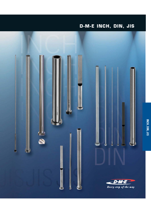
INCH, DIN, JISOnline Price GuideU.S. 800-626-6653 N Canada 800-387-6600 N Online Price GuideEJECTOR BLADESINCH EJECTOR BLADES...........................252-253NPrecision made of superior quality H13 type thermal shock resisting hotwork die steel N Hot-forged heads provide uniform grain flow, higher tensile strength N Core hardness 40-45 HRC N O utside diameter nitrided to 65-74 HRC hardness and finished to minimize wear N H eads annealed for easy machining Items in stock 2-3 week deliveryContact D-M-E for quoteI N C H P i n s , S l e e v e s , B l a d e s | I N C H E j e c t o r P i n s – H 13 N i t r i d e d – S t r a i g h tD –.0003–.0006+.000NPrecision made of superior quality H13 type thermal shock resisting hotwork die steelNHot-forged heads provide uniform grain flow, higher tensile strength N C ore hardness 40-45 HRC NO utside diameter nitrided to 65-74 HRC hardness and finished to minimize wearNH eads annealed for easy machining NC enterless groundD diameter*HOW TO ORDER: S pecify Item Number by combining Item Number Prefix and the length (L dimension) desired.N Omit spaces and dashes, as shown. Examples: EX2M6, EX8M14N Add “OS” for .005" oversize diameters. Examples: EX2M6OS, EX5M10OS, EX8M10OS NOTE: For 2" Shoulder, no suffix is used. Examples: EX3M6, EX7M10NOTE: For 2" Shoulder Length, no suffix should be used (see example below).D –.0003–.0006+.000 *HOW TO ORDER: S pecify Item Number by combining Item Number Prefix and the length (L dimension) desired.N Omit spaces and dashes, as shown. Examples: EX2M612SH, EX8M1412SH N Add “OS” for .005" oversize diameters. E xamples: EX3M612SHOS, EX3M612SHOSNOTE: 12SH suffix shown in chart for 1/2" Shoulder length. Examples: EX3M612SH, EX7M1012SH| Items in stock 2-3 week deliveryContact D-M-E for quoteItems in stock 2-3 week deliveryContact D-M-E for quoteNHigher core hardness makes the THX pins ideal for use in die cast dies or other high temperature applicationsN Core hardness of 50-55 HRC minimizes nicking, dishing and bending N Non-chipping surface treatment of 65-74 HRC alleviates flashingN Annealed and finished heads permit easy machiningN C enterless ground D diameter*HOW TO ORDER: S pecify Item Number by combining Item Number Prefix and the length (L dimension) desired. N Omit spaces & dashes, as shown. Examples: THX0910, THX4118N Precede 6" length with a zero. Examples: THX0906, THX3306 N Add “OS” for .005" oversize diameters. Examples: THX0306NSOS, THX0906OS, THX2514OS, THX3310OS NOTE: NS suffix shown in chart for No Shoulder for items THX03 through THX08. Examples: THX306NS, THX710NSI N C H P i n s , S l e e v e s , B l a d e s | I N C H H i g h -H a r d n e s s E j e c t o r P i n s – H 13 N i t r i d e d – S t r a i g h tItems in stock 2-3 week deliveryContact D-M-Efor quoteINCH Pins, Sleeves, Blades | Keyed Ejector PinsINFORMATION KEY:D = Pin Diameter H = Head Diameter K = Head Thickness L = LengthMaterial: H-13 / 1.2344 / SKD61Surface Treatment:NitridedSurface Hardness: 65 min. HRC Core Hardness : 50-55 HRCNPrecision-machined flat on head keeps pin from rotatingN Made from superior quality thermal shock-resisting hotwork steel N C ore hardness of 50-55 HRC makes these pins ideal for use in die-cast dies or other high temperature applications N A nnealed hot-forged heads provide uniform grain flow while allowing for easier machiningKeyed Ejector Pins – THXKD±.002I N C H P i n s , S l e e v e s , B l a d e s | I N C H C l o s e T o l e r a n c e M -2 T h r o u g h -H a r d e n e d E j e c t o r P i n sN Industry-leading .0002" tolerance band N Centerless ground D diameterN P recision made of superior quality M-2 high-speed tool steel N Superior wear resistanceN Exceptional performance at elevated temperaturesNHot-forged heads provide uniform grain flow, higher tensile strength2" Shoulder Ejector Pins – EJP-IMH.031 R58-62 HRC*HOW TO ORDER: S pecify Item Number by adding L length in inches (06 or 10) after Item Number Prefix.N Include zeros and dashes, as shown.Examples: EJP-IMH-0062-06; EJP-IMH-0125-10; EJP-IMH-0250-10Items in stock2-3 week deliveryContact D-M-E for quoteU.S. 800-626-6653 N Canada 800-387-6600 N Manufactured from superior quality, thermal shock-resistant hotwork steel. Pin heads are hot forged and annealed for toughness. The pin surface is nitrided for wear resistance.Fabricados en acero de calidad superior resistente a choque termico. Las cabezas son forjadas en caliente y aleadas para mejor resistencia. La superfice del pernoes nitrurada para resistencia al desgaste.MoldBasics Inch Ejector Pins – Straight – Nitrided Pernos Expulsores Rectos Nitrurados – (MB-EJP-IHN*HOW TO ORDER: S pecify Item Number starting with the Item Number Prefix (with Diameter),then add L length. Include zeros and dashes.Examples: MB-EJP-IHN-0062-06, MB-EJP-IHN-0500-14 *PARA ORDENAR: E specifique el número del articulo empezando con el número del prefijo, D Diámetro, y L Longitud, incluya ceros y guiones.Examples: MB-EJP-IHN-0062-06, MB-EJP-IHN-0500-14| MoldBasics ™ INCH Ejector Pins – Straight – NitridedItems in stock2-3 week deliveryContact D-M-E for quoteU.S. 800-626-6653 N Canada 800-387-6600 N †S13 and S15 have a 1.75 bearing length.All sleeves are for use with D-M-E Inch Ejector Pins.eject the piece part.e without machining if wear occurs. the ejector pin is located between cavity inserts. Using a sleeve as ab ushing provides a full bearing diameter for the pin.Precision made of superior quality thermal shock resisting hotwork die steel Hot-forged heads provide uniform grain flow, higher tensile strengthO utside diameter nitrided to 65-74 HRC hardness and finished to minimize wear C enterless ground and polished outer diameter I nside bearing diameter is 30-35 HRC hardness and finished honedNL ead-in taper designed to allow interference-free entry of the ejector pin into the sleeve*HOW TO ORDER: C ombine Item Prefix and the length (L dimension) desired. Examples: S15M6, S39M10I N C H P i n s , S l e e v e s , B l a d e s | I N C H E j e c t o r S l e e v e s – N i t r i d e d O .D .Items in stock2-3 week deliveryContact D-M-E for quote†S13 and S15 have a 1.75 bearing length.All sleeves are for use with D-M-E Inch Ejector Pins.Ø DN Precision made of superior quality thermal shockresisting hotwork die steelN Hot-forged heads provide uniform grain flow,higher tensile strengthN O utside diameter nitrided to 65-74 HRC hardnessand finished to minimize wearN C enterless ground and polished outer diameterN I nside bearing diameter is nitrided to 65-74 HRChardness and finished honedN L ead-in taper designed to allow interference-freeentry of the ejector pin into the sleeveN S ND sleeve I.D. is nitrided for prolonged wearresistance and improved lubricity*HOW TO ORDER: C ombine Item Prefix and the length (L dimension) desired.N Precede single digit lengths with a zero.Examples: SND2506, SND1710|INCH Ejector Sleeves – Nitrided O.D. & I.D.Items in stock2-3 weekdeliveryContact D-M-Efor quoteU.S. 800-626-6653 N Canada 800-387-6600 N U.S. 800-626-6653 N Canada 800-387-6600 N FOR STRENGTHAll items in stock. Specify item number and quantity.NBlade thickness and width are held to close tolerance: +.0000/-.0003N Precision made of superior quality M2 high- speed tool steel N T hrough-hardened to 58-62 HRC for superior wear resistance N H eads annealed for easy machining N O ne-piece construction for increased strength I N C H P i n s , S l e e v e s , B l a d e s | I N C H E j e c t o r B l a d e sINCH Pins, Sleeves, Blades|INCH Ejector BladesU.S. 800-626-6653 N Canada 800-387-6600 N U.S. 800-626-6653 N Canada 800-387-6600 N †Heads of 3"-length pins are not annealed. If annealed heads on 3"-length pins are required, they must be special ordered. (Alternately, you may purchase 6" pins and cut to required length.)Typical applicationNPrecision made of superior quality hotwork die steel standard hardness 30-35 HRCN Heads are hot-forged for uniform grain flow, higher tensilestrength, then annealed to permit easier machining and stamping N +.0008"/+.0003" tolerance on pin diameter ensures a close fit for coring purposesN Pin body and head are finish ground N C enterless ground and polished outer diameter*HOW TO ORDER: C ombine Item Number Prefix and the length (L dimension) desired. Examples: C9M3, C33M10I N C H P i n s , S l e e v e s , B l a d e s | I N C H C o r e P i n s – H 13 – S t a n d a r d M e d i u m H a r d n e s sItems in stock 2-3 week deliveryContact D-M-E for quoteU.S. 800-626-6653 N Canada 800-387-6600 N NPrecision made of superior quality hotwork die steel in high hardness 50-55 HRCN Heads are hot-forged for uniform grain flow, higher tensilestrength, then annealed to permit easier machining and stamping N +.0008"/+.0003"- tolerance on pin diameter ensures a close fit for coring purposesN Pin body and head are finish ground N Centerless ground and liquid polished†Heads of 3"-length pins are not annealed. If annealed heads on 3"-length pins are required, they must be special ordered. (Alternately, you may purchase 6" pins and cut to required length.)*HOW TO ORDER: C ombine Item Number Prefix and the length (L dimension) desired.Examples: CX9M3, CX33M10INCH Pins, Sleeves, Blades | INCH Core Pins – High HardnessINCH Core Pins – CXSpecials available.See “Special Pins and Sleeves.”Items in stock 2-3 week deliveryContact D-M-E for quoteD-M-E DIN Pins, Sleeves, BladesA COMPREHENSIVE LINEOF DIN EJECTOR PRODUCTS DIN Pins, Sleeves, BladesE JECTOR PINSE JP-EHN (NITRIDED) (264)EJP-ELH (HARDENED) (265)SHOULDER EJECTOR PINSEJP-EHN (NITRIDED) (266)EJP-ELH (HARDENED)...........................267 EJECTOR SLEEVESEJS-EHN (NITRIDED) (268)EJS-ELH (HARDENED) (269)EJECTOR BLADESEJB-EHN (NITRIDED) (270)EJB-ELH (HARDENED) (271)CORE PINSCRP-EHH (HARDENED) (272)CRP-ECS (PERFORMANCE) (273)F AX ORDER FORM – SPECIAL DIN PINS & SLEEVESF AXABLE QUOTE REQUEST FORM..................275-276TOCU.S. 800-626-6653 N Canada 800-387-6600 N INFORMATION KEY:D = Pin Body Diameter H = Head Diameter K = Head Thickness L = LengthStandard:DIN/ISO TypeMaterial:1.2344 (AISI H13 Type) SteelSurface Treatment: NitridedMax. Temp.: 500˚-550˚C (932˚-1022˚F)Dimensions: Shown in Millimeters (mm)Expulsores I Extractores I Ejecteurs Epingles I AuswerferstifteD I N P i n s , S l e e v e s , B l a d e s | D I NE j e c t o r P i n s – N i t r i d e dDIN Ejector Pins – EJP-EHNItems in stock2-3 week deliveryContact D-M-E for quoteU.S. 800-626-6653 N Canada 800-387-6600 N INFORMATION KEY:D = Pin Body Diameter H = Head Diameter K = Head Thickness L = LengthStandard:DIN/ISO TypeMaterial:1.2210 (AISI L2 Type) SteelSurface Treatment: None (Through-Hardened) Max. Temp.: 250˚C (482˚F)Dimensions: Shown in Millimeters (mm)Ø* “(AH)” is only a cross-reference to current D-M-E Europe Catalog item prefix numbers.Expulsores I Extractores I Ejecteurs epingles I AuswerferstifteDIN Pins, Sleeves, Blades | DIN Ejector Pins – HardenedDIN Ejector Pins – EJP-EHHItems in stock2-3 week deliveryContact D-M-E for quoteINFORMATION KEY:D = Pin Body Diameter E = Shoulder Diameter H = Head Diameter K = Head ThicknessL = LengthS = Shoulder LengthStandard: DIN/ISO Type Material: 1.2344 (AISI H13 Type) Steel Surface Treatment: Nitrided Max. Temp.: 500°-550°C (932°-1022°F)Dimensions: Shown in Millimeters (mm)* “(C)” is only a cross-reference to current D-M-E Europe Catalog item prefix numbers.Expulsores con hombro I Extractores I Ejecteurs epingles I Auswerferstifte D INPins,Sleeves,Blades|D I NShoulder Ejec torPins–Ni tr idedDIN Shoulder Ejector Pins – EJP-EHN Items in stock2-3 week deliveryContact D-M-E for quoteINFORMATION KEY:D = Pin Body DiameterE = Shoulder DiameterH = Head DiameterK =Head ThicknessL =LengthS = Shoulder LengthStandard: DIN/ISO TypeMaterial: 1.2210 (AISI L2 Type) SteelSurface Treatment: None (Through-Hardened)Max. Temp.: 250˚C (482˚F)Dimensions: Shown in Millimeters (mm)Expulsores con hombro I Extractores I Ejecteurs epingles I Auswerferstifte|DIN Shoulder Ejector Pins – Hardened DIN Shoulder Ejector Pins – EJP-ELHItems in stock 2-3 week delivery Contact D-M-E for quoteINFORMATION KEY:D = Pin Body DiameterE = Shoulder DiameterH = Head DiameterK =Head ThicknessL =LengthS = Shoulder LengthStandard: DIN/ISO TypeMaterial: 1.2210 (AISI L2 Type) SteelSurface Treatment: None (Through-Hardened)Max. Temp.: 250˚C (482˚F)Dimensions: Shown in Millimeters (mm)Expulsores con hombro I Extractores I Ejecteurs epingles I Auswerferstifte|DIN Shoulder Ejector Pins – Hardened DIN Shoulder Ejector Pins – EJP-ELHItems in stock 2-3 week delivery Contact D-M-E for quoteØ D INFORMATION KEY:D = Inside DiameterE = Outside Diameter H = Head DiameterK = Head Thickness L = Length N = Bearing LengthStandard: DIN/ISO Type Material: 1.2210 (AISI L2 Type) SteelSurface Treatment: None (Through-Hardened)Max. Temp.: 250°C (482°F)Dimensions: Shown in Millimeters (mm)* “(KS)” is only a cross-reference to current D-M-E Europe Catalog item prefix numbers.Mangas expulsoras I Extractores tubulares I Ejecteurs tubulaires I AuswerferhülsenDIN Pins, Sleeves, Blades | DIN Ejector Sleeves – HardenedDIN Ejector Sleeves – EJS-ELHItems in stock2-3 weekdelivery Contact D-M-E for quote0-0.0150-0.015 (Ref. Only ~68 HRC)INFORMATION KEY:D = Shoulder Diameter H = Head Diameter K = Head Thickness L = Length S = Shoulder Length T = Blade Thickness W = Blade Width Standard: DIN/ISO Type Material: 1.2344 (AISI H13 Type) Steel Surface Treatment: Nitrided Max. Temp.: 500°-550°C (932°-1022°F)Dimensions: Shown in Millimeters (mm)* “(FW)” is only a cross-reference to current D-M-E Europe Catalog item prefix numbers.Expulsores planos I Extractores laminares I Ejecteurs lames I Auswerferklingen D INPins,Sl eeves,Bl ades|D INEjector Blad es–Nit ridedDIN Ejector Blades – EJB-EHN Items in stock2-3 week deliveryContact D-M-E for quote-0.015-0.015INFORMATION KEY:D = Shoulder Diameter H = Head Diameter K = Head Thickness L = Length S = Shoulder Length T = Blade Thickness W = Blade WidthStandard: DIN/ISO Type Material: 1.2210 (AISI L2 Type) Steel Surface Treatment: None (Through-Hardened)Max. Temp.: 250°C (482°F)Dimensions: Shown in Millimeters (mm)* “(FK)” is only a cross-reference to current D-M-E Europe Catalog item prefix numbers.Expulsores planos I Extractores laminares I Ejecteurs lames I Auswerferklingen| DIN Ejector Blades – HardenedDIN Ejector Blades – EJB-ELHItems in stock2-3 week deliveryContact D-M-E for quoteINFORMATION KEY:D = Pin Body Diameter H = Head Diameter K = Head Thickness L = Length Standard:DIN/ISO TypeMaterial: 1.2344 (AISI H13 Type) Steel Surface Treatment: None (Through-Hardened) Max. Temp.: 500°-550°C (932°-1022°F)Dimensions: Shown in Millimeters (mm)* “(AHX)” is only a cross-reference to current D-M-E Europe Catalog item prefix numbers.Pernos moldeadores I Pernos moldantes I Epingles au centre I Kernstifte D INPins,Sl eeves,Bl ades|D INCoreP ins–Har denedDIN Core Pins – CRP-EHH Items in stock2-3 weekdeliveryContact D-M-E for quote0HIGH THERMALCONDUCTIVITY PINS Advantages:• Reduced cycle time • 5 times betterconductivity than steel • Improved part quality • Lower machining costs• Longer service life INFORMATION KEY:D = Pin Body DiameterH = Head DiameterK = Head Thickness L = Length Standard: DIN/ISO Type Material: Beryllium-free Copper based alloy Surface Treatment: NoneMax. Temp.: 350°C (662°F)Dimensions: Shown in Millimeters (mm)* “(PCM)” is only a cross-reference to current D-M-E Europe Catalog item prefix numbers.Pernos moldeadores I Pernos moldantes I Epingles au centre I KernstifteDIN Pins, Sleeves, Blades | DIN Core Pins – PerformanceDIN Core Pins – CRP-ECSItems in stock2-3 weekdelivery Contact D-M-E for quoteEJECTOR PINSØ DLKØ H R 0.5 MAX.+4 +1-0.05-0.15NOTE: All dimensions are in mm.Items in stock Contact D-M-E for quoteKEY TO CHARTHOW TO ORDER: U se Item Number in charts above for ordering.INFORMATION KEY:D = Pin Body Diameter H = Head Diameter K = Head Thickness L = Length Standard: JISMaterial: SKD61 (H-13)Surface Treatment: NitridedSurface Hardness: 70-72 Rc (HV 1000 ± 100) Core Hardness : 40 HRC±2J I S P i n s , S l e e v e s , B l a d e s | J I S E j e c t o r P i n s – S t r a i g h tJIS Ejector Pins – JFXNOTE: All dimensions are in mm.Items in stockContact D-M-Efor quoteKEY TO CHARTHOW TO ORDER: U se Item Number in charts above for ordering.INFORMATION KEY:D = Pin Inner DiameterE = Pin Body DiameterH = Head DiameterK = Head ThicknessL = LengthN = ID Bearing LengthStandard: JISMaterial: SKD61 (H-13)Surface Treatment: NitridedSurface Hardness: 70-72 Rc(HV 1000 ± 100)Core Hardness: 32 HRC ±2JIS Pins, Sleeves, Blades|JIS Ejector SleevesJIS Ejector Sleeves – JFS-0.01NOTE: All dimensions are in mm.HOW TO ORDER: U se Item Number in charts above for ordering.INFORMATION KEY:D = Pin Body Diameter H = Head Diameter K = Head Thickness L = LengthN = ID Bearing Length T = Blade Thickness W = Blade Width Material: SKS21Surface Treatment: Nitrided Surface Hardness : 58 HRC ±2J I S P i n s , S l e e v e s , B l a d e s | J I S E j e c t o r B l a d e sJIS Ejector Blades – JEB。
(完整)冲压模具外文文献
Progressive DieProgressive die has the following advantages1) Class into the module is multi-process dies, in a mold can include punching, bending,forming and drawing a variety of multi—pass process, with a higher than the compound die labor productivity, but also can produce quite complex stampings;2) Progressive Die Operation Security, because staff do not have to enter the danger zone;3) Class Progressive Die Design, The process can be distributed。
Do not focus on one station , there is no Compound Dies "Minimum wall thickness" problem. Therefore relatively high mold strength, longer life expectancy。
4) Progressive Die Easy Automation That is easy to Automatic feeding ,Autoout of parts Automatic lamination;5) Class Progressive die can be High—speed press production, because the workpiece can be directly down the drain and waste;6) Use Class Progressive die can be Reduce the presses, semi-finished products to reduce transport. Workshop area and storage space can be greatly reduced. Progressive Dies The disadvantage is that complex structure, manufacturing of high precision, long life cycle and high costs. Because of progressive die is a To the workpiece, the shape of successive out, each punch has a positioning error, is more difficult to maintain stability in the workpiece, the relative position of the one—off appearance。
精密不锈钢生产流程

精密不锈钢生产流程英文回答:The production process of precision stainless steel involves several steps to ensure the high quality and precision of the final product. Let me walk you through the process.1. Material Preparation: The first step is to selectthe appropriate stainless steel material for the production. This material should have the desired properties, such as corrosion resistance, strength, and durability. Thestainless steel is usually in the form of sheets or coils.2. Cutting and Shaping: The stainless steel sheets or coils are then cut into the desired sizes and shapes using various cutting techniques, such as shearing, sawing, or laser cutting. This step ensures that the stainless steelis prepared to the required dimensions for further processing.3. Forming and Bending: The cut stainless steel pieces are then formed and bent into the desired shapes. This can be done through processes like rolling, bending, or stamping. These techniques help in creating complex shapes or structures from the stainless steel material.4. Welding: In some cases, the formed stainless steel pieces need to be joined together. Welding is the process used to fuse the separate pieces into a single component. Different welding techniques, such as TIG (Tungsten Inert Gas) or MIG (Metal Inert Gas), are used depending on the specific requirements of the product.5. Surface Treatment: The surface of the stainless steel is often treated to enhance its appearance and improve its resistance to corrosion. Processes like polishing, passivation, or electroplating are used to achieve a smooth and shiny surface finish.6. Quality Control: Throughout the production process, strict quality control measures are implemented to ensurethe precision and quality of the stainless steel products. This includes inspection of dimensions, surface finish, and mechanical properties to meet the specified standards.7. Packaging and Shipping: Once the precision stainless steel products are ready, they are carefully packaged to protect them from damage during transportation. Proper labeling and documentation are also done to ensure smooth shipping and delivery to the customers.中文回答:精密不锈钢的生产流程包括多个步骤,以确保最终产品的高质量和精度。
低频活动漂浮潜水船声探测系统(LFATS)说明书

LOW-FREQUENCY ACTIVE TOWED SONAR (LFATS)LFATS is a full-feature, long-range,low-frequency variable depth sonarDeveloped for active sonar operation against modern dieselelectric submarines, LFATS has demonstrated consistent detection performance in shallow and deep water. LFATS also provides a passive mode and includes a full set of passive tools and features.COMPACT SIZELFATS is a small, lightweight, air-transportable, ruggedized system designed specifically for easy installation on small vessels. CONFIGURABLELFATS can operate in a stand-alone configuration or be easily integrated into the ship’s combat system.TACTICAL BISTATIC AND MULTISTATIC CAPABILITYA robust infrastructure permits interoperability with the HELRAS helicopter dipping sonar and all key sonobuoys.HIGHLY MANEUVERABLEOwn-ship noise reduction processing algorithms, coupled with compact twin line receivers, enable short-scope towing for efficient maneuvering, fast deployment and unencumbered operation in shallow water.COMPACT WINCH AND HANDLING SYSTEMAn ultrastable structure assures safe, reliable operation in heavy seas and permits manual or console-controlled deployment, retrieval and depth-keeping. FULL 360° COVERAGEA dual parallel array configuration and advanced signal processing achieve instantaneous, unambiguous left/right target discrimination.SPACE-SAVING TRANSMITTERTOW-BODY CONFIGURATIONInnovative technology achievesomnidirectional, large aperture acousticperformance in a compact, sleek tow-body assembly.REVERBERATION SUPRESSIONThe unique transmitter design enablesforward, aft, port and starboarddirectional transmission. This capabilitydiverts energy concentration away fromshorelines and landmasses, minimizingreverb and optimizing target detection.SONAR PERFORMANCE PREDICTIONA key ingredient to mission planning,LFATS computes and displays systemdetection capability based on modeled ormeasured environmental data.Key Features>Wide-area search>Target detection, localization andclassification>T racking and attack>Embedded trainingSonar Processing>Active processing: State-of-the-art signal processing offers acomprehensive range of single- andmulti-pulse, FM and CW processingfor detection and tracking. Targetdetection, localization andclassification>P assive processing: LFATS featuresfull 100-to-2,000 Hz continuouswideband coverage. Broadband,DEMON and narrowband analyzers,torpedo alert and extendedtracking functions constitute asuite of passive tools to track andanalyze targets.>Playback mode: Playback isseamlessly integrated intopassive and active operation,enabling postanalysis of pre-recorded mission data and is a keycomponent to operator training.>Built-in test: Power-up, continuousbackground and operator-initiatedtest modes combine to boostsystem availability and accelerateoperational readiness.UNIQUE EXTENSION/RETRACTIONMECHANISM TRANSFORMS COMPACTTOW-BODY CONFIGURATION TO ALARGE-APERTURE MULTIDIRECTIONALTRANSMITTERDISPLAYS AND OPERATOR INTERFACES>State-of-the-art workstation-based operator machineinterface: Trackball, point-and-click control, pull-down menu function and parameter selection allows easy access to key information. >Displays: A strategic balance of multifunction displays,built on a modern OpenGL framework, offer flexible search, classification and geographic formats. Ground-stabilized, high-resolution color monitors capture details in the real-time processed sonar data. > B uilt-in operator aids: To simplify operation, LFATS provides recommended mode/parameter settings, automated range-of-day estimation and data history recall. >COTS hardware: LFATS incorporates a modular, expandable open architecture to accommodate future technology.L3Harrissellsht_LFATS© 2022 L3Harris Technologies, Inc. | 09/2022NON-EXPORT CONTROLLED - These item(s)/data have been reviewed in accordance with the InternationalTraffic in Arms Regulations (ITAR), 22 CFR part 120.33, and the Export Administration Regulations (EAR), 15 CFR 734(3)(b)(3), and may be released without export restrictions.L3Harris Technologies is an agile global aerospace and defense technology innovator, delivering end-to-endsolutions that meet customers’ mission-critical needs. The company provides advanced defense and commercial technologies across air, land, sea, space and cyber domains.t 818 367 0111 | f 818 364 2491 *******************WINCH AND HANDLINGSYSTEMSHIP ELECTRONICSTOWED SUBSYSTEMSONAR OPERATORCONSOLETRANSMIT POWERAMPLIFIER 1025 W. NASA Boulevard Melbourne, FL 32919SPECIFICATIONSOperating Modes Active, passive, test, playback, multi-staticSource Level 219 dB Omnidirectional, 222 dB Sector Steered Projector Elements 16 in 4 stavesTransmission Omnidirectional or by sector Operating Depth 15-to-300 m Survival Speed 30 knotsSize Winch & Handling Subsystem:180 in. x 138 in. x 84 in.(4.5 m x 3.5 m x 2.2 m)Sonar Operator Console:60 in. x 26 in. x 68 in.(1.52 m x 0.66 m x 1.73 m)Transmit Power Amplifier:42 in. x 28 in. x 68 in.(1.07 m x 0.71 m x 1.73 m)Weight Winch & Handling: 3,954 kg (8,717 lb.)Towed Subsystem: 678 kg (1,495 lb.)Ship Electronics: 928 kg (2,045 lb.)Platforms Frigates, corvettes, small patrol boats Receive ArrayConfiguration: Twin-lineNumber of channels: 48 per lineLength: 26.5 m (86.9 ft.)Array directivity: >18 dB @ 1,380 HzLFATS PROCESSINGActiveActive Band 1,200-to-1,00 HzProcessing CW, FM, wavetrain, multi-pulse matched filtering Pulse Lengths Range-dependent, .039 to 10 sec. max.FM Bandwidth 50, 100 and 300 HzTracking 20 auto and operator-initiated Displays PPI, bearing range, Doppler range, FM A-scan, geographic overlayRange Scale5, 10, 20, 40, and 80 kyd PassivePassive Band Continuous 100-to-2,000 HzProcessing Broadband, narrowband, ALI, DEMON and tracking Displays BTR, BFI, NALI, DEMON and LOFAR Tracking 20 auto and operator-initiatedCommonOwn-ship noise reduction, doppler nullification, directional audio。
辊弯成型工艺研究

辊弯成型工艺研究辊弯成型工艺研究是金属材料加工中,一种常见的成形工艺。
它利用辊弯机将金属材料进行弯曲,从而得到所需要的外形尺寸、曲率半径及几何精度的带弯部件。
辊弯成型工艺是一种比较古老的工艺,早在20世纪50年代就开始使用。
在辊弯成型工艺中,金属材料通过两个相对运动的辊子,实现弯曲加工。
根据不同的材料及加工要求,可选择不同类型的辊弯机,如气动式辊弯机、液压式辊弯机、数控辊弯机等。
辊弯机可分为卧式及立式两种,其中立式辊弯机又可分为3轴辊弯机、4轴辊弯机及5轴辊弯机。
辊弯成型工艺具有加工精度高、效率高、成本低等优点,在航空航天、汽车、冶金、电子、机械等行业被广泛应用。
但是,辊弯成型工艺也存在一些缺点,如加工尺寸受到加工参数的限制,加工厚度范围狭窄,加工能力受到材料性能限制等。
因此,在辊弯成型工艺研究中,需要考虑许多因素,如设计理念、选择辊弯机型号、选择加工参数、选择工具材料等。
首先,要确定好设计理念,以便正确的选择辊弯机型号及加工参数。
其次,应仔细研究辊弯机的结构特点,确定合适的机型,以保证加工效率及加工精度。
在选择加工参数方面,要根据材料的性能及加工精度,选择合理的加工参数,以保证加工效果。
另外,在选择工具材料方面,也要考虑到工具使用寿命、曲率半径及弯曲精度等因素。
总之,辊弯成型工艺研究是一项比较复杂的工作,需要考虑许多因素,以保证加工效果及成型精度。
此外,要根据实际情况,不断优化辊弯成型工艺,以提高加工效率及精度,满足不断发展的加工要求。
Roll bending forming technology research is a common forming process in metal material processing. It uses roll bending machine to bend the metal material, so as to obtain the bent parts with required shape size, curvature radius and geometric precision. Roll bending forming technology is a relatively old technology, which has been used since the 1950s.In roll bending forming process, the metal material is bent by two relative moving rolls. According to different materials and processing requirements, different types of roll bending machines can be selected, such as pneumatic rollbending machine, hydraulic roll bending machine, CNC roll bending machine, etc. Roll bending machines can be divided into horizontal andvertical types, among which vertical roll bending machines can be further divided into 3-axis, 4-axis and 5-axis roll bending machines.Roll bending forming technology has advantages of high processing accuracy, high efficiency and low cost. It is widely used in aerospace, automobile, metallurgy, electronics, machinery and other industries. However, roll bending forming technology also has some disadvantages, such as the processing size is limited by processing parameters, the processing thickness range is narrow, and the processing capacity is limited by material properties.Therefore, in the research of roll bending forming technology, many factors need to be considered, such as design concept, selection of roll bending machine model, selection of processing parameters, selection of tool materials, etc. First of all, it is necessary to determine the designconcept in order to select the right roll bending machine model and processing parameters. Secondly, the structure characteristics of the roll bending machine should be studied carefully to determinethe appropriate model in order to ensure the processing efficiency and accuracy. In terms of selecting processing parameters, reasonable processing parameters should be selected according to the material properties and processing accuracy to ensure the processing effect. In addition, when selecting the tool materials, the service life of the tools, curvature radius and bending accuracy should also be taken into account.In a word, the research of roll bending forming technology is a complicated work, which needs to consider many factors to ensure the processing effect and forming accuracy. In addition, according to the actual situation, the roll bending forming technology should be optimized continuously to improve the processing efficiency and accuracy, so as to meet the constantly developing processing requirements.。
斯韦格洛克- 管道弯管工具与配件 手册说明书
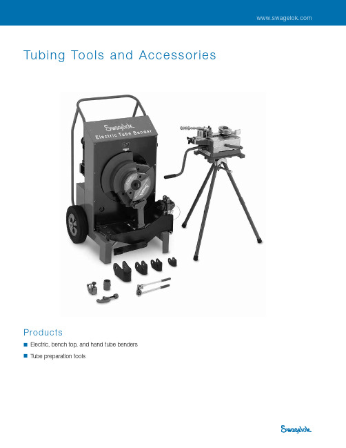
Tubing Tools and Accessories 1 Tubing Tools and AccessoriesProducts■ Electric, bench top, and hand tube benders■ Tube preparation tools2 Tubing, Tubing Tools, and Welding SystemT U B I N G T O O L STube BendersSwagelok ® benders provide high-quality bends on fractional and metric tubingmade from materials that can be used with Swagelok tube fittings. These easy-to-use tube benders reduce installation time and effort as well as the potential for wrinkling or other damage to the tubing during bending.ContentsTube BendersElectric (2)Bench Top ............... 3 Hand . (5)Tube Preparation ToolsTube Cutter (6)Tube Sawing Guide ........ 6 Tube Deburring Tools ...... 6 Tube Gripper Pad (6)Features■ Electronic control ■ 1 to 110° bending range■ 1 to 2 in. outside diameter (0.049to 0.220 in. wall thickness) and 25 to 50 mm outside diameter (1.2 to 5.0 mm wall thickness) tubing range■ One bend shoe for 1, 1 1/4, 1 1/2, and2 in. sizes■ One bend shoe for 25, 32, 38, and50 mm sizesTechnical Data■ Dimensions—vertical position: 44 in. (112 cm) high, 29 in. (74 cm)wide, 30 in. (76 cm) deep■ Weight—420 lb (191 kg)■ Power requirementsM S-TBE-1—115 V (ac), 50/60 Hz; maximum current—13 A M S-TBE-2—230 V (ac), 50/60 Hz; maximum current—7 A See Ordering Information, page 4.See the Swagelok Electric Tube Bender User’s Manual, MS-13-138, for complete setup and operating instructions.Electric Tube BendersTubing DataMinimum tube length, bend radius, and wall thickness limits required to make a 90° bend in annealed tubing are listed below. Some applications require specific bend radii; consult applicable codes for bend radius requirements. Refer to Tubing Data catalog , MS-01-107, for suggested tubing wall thickness for use with Swagelok tube fittings.Fractional TubingMetric TubingTubing Tools and Accessories 3TUBING TOOLS Bench Top Tube BendersFeatures■ Rugged, lightweight aluminum construction■ 1 to 180° bending range■ 1/4 to 1 1/4 in. outside diameter (0.028 to 0.120 in. wallthickness) and 6 to 30 mm outside diameter (0.8 to 3.0 mmwall thickness) tubing range■ Steel bend shoes required for:■1 in. outside diameter tubing with greater than 0.095 in.wall thickness■25 mm tubing with greater than 2.4 mm wall thickness■a ll sizes of Alloy 2507 tubing■a ll sizes of heavy-wall annealed stainless steel tubing■a ll sizes of cold-drawn 1/8-hard stainless steel seamlesstubing.■a ll sizes of IPT medium and high pressure tubing.■ Includes grease gun and metal carrying case for storage■ Manual model can be operated with a 1/2 in. drill motorusing optional torque clutch and support arm.■ CE compliantTubing DataThe bend radius and wall thickness limits for making a bend in annealed tubing are listed below. Some applications requirespecific bend radii; consult applicable codes for bend radius requirements. Refer to Swagelok Tubing Data catalog, MS-01-107for suggested tubing wall thickness for use with Swagelok tube fittings.Fractional Tubing Metric TubingManual ModelElectric ModelTube Benders➀9/16 in. bend shoe is steel and for use with IPT tubing only.See the Swagelok Bench Top Tube Bender User’s Manual, MS-13-145, for completesetup and operating instructions.Technical Data■ Dimensions—tube bender in case:14 1/2 in. (37 cm) high, 21 in. (53 cm) wide, 11 in. (28 cm)deep■ Weight—tube bender in case, excluding tools:Manual model—75 lb (34 kg)Electric model—79 lb (36 kg)■ Power requirements (electric model)M S-BTB-1—110 V (ac), 50/60 Hz; maximum current—10 AM S-BTB-2—230 V (ac), 50/60 Hz; maximum current—5 ASee Ordering Information, page 4, and Options andAccessories, page 4.4 Tubing, Tubing Tools, and Welding SystemTUBINGTOOLSOrdering Information, Electric and Bench Top Tube Benders1. Select a basic ordering number.Example: MS-BTB-1-2. Add a power cord designator (electric models).Example: MS-BTB-1-13. Add a user’s manual language designator.Example: MS-BTB-1-1-E4. Add a tool kit designator.Example: MS-BTB-1-1-E-FKITBench Top Tube Bender KitsTo substitute a steel bend shoe for a 1 in. or 25 mm aluminumbend shoe, add -S16 to the fractional kit ordering number or-S25M to the metric kit ordering number. These are the onlysizes permitted to be changed to steel in these kits.Example: MS-BTB-1-1-E-FKIT-S16-FKIT and -MKIT kits contain tooling for the tubing sizes listedin the table above only. Tooling for 1 1/4 in, 28 mm, and 30mm must be ordered separately and is only offered in steel.Individual tool kits with aluminum or steel bend shoes for1/4 in., 3/8 in., 6 mm, and 10 mm tubing must be orderedseparately; see Options and Accessories, Bench Top TubeBenders, page 5.Tube Benders➀N ot available in European Union or China.N ot available in European Union or China.Tubing Tools and Accessories 5TUBING TOOLSTo order a complete aluminum fractional kit (1/2 in., 5/8 in., 3/4in., 7/8 in., and 1 in.) use ordering number MS-BTT-K-F-CASE.For a metric kit (12 mm, 16 mm, 18 mm, 20 mm, 22 mm, and25 mm) use ordering number MS-BTT-K-M-CASE. These kitsare only available in aluminum and contains the bend shoes,all rollers, and a carrying case. We do not offer kits in steel.■ The tripod provides portable support for the tube bender.Ordering number: MS-BTB-A-TP■ The torque clutch and support arm kit allows the manualmodel to be operated with a 1/2 in. drill motor.Ordering number: MS-BTB-A-TCSA■ The foot pedal can be used in place of the toggle switch tooperate the electric model.Ordering number: MS-BTB-A-FSRefer to Bench Top Tube Bender User’s Manual, MS-13-145,for additional accessories.Heavy-Duty Shipping CaseThe upgraded, rugged plastic customshipping case provides maximumprotection of the manual or electricbench top tube bender during transportand enhances portability with anextendable handle and wheels. The casecan also accommodate a an aluminumfractional or metric tool kit.Case dimensions, with handles foldedand retracted:30.5 H by 20.5 W by 15.5 D in. approx(77.5 by 52.1 by 39.4 cm approx).Ordering number: MS-BTB-CASE-SHIPTube BendersHand Tube BendersSwagelok hand tubebenders provideconsistent, high-qualitybends in tubing madefrom materials that canbe used with Swageloktube fittings.Features■ The hand tube bender is available in 1/8, 1/4, 5/16, 3/8, and1/2 in., as well as 3, 6, 8, 10, and 12 mm tubing sizes.■ Clevis handle design provides enhanced leverage for bendsgreater than 90°.■ Roll dies reduce bending force and tube ovality, ascompared to conventional slide block design.■ 1 to 180° bending range.The hand tube bender cannot be used for Alloy 2507tubing over 1/4 in. or for medium-pressure tubing.Refer to Hand Tube Bender Manual, MS-13-43, for additionalinformation.Tubing DataSee Ordering Information, below, for bend radius data.Some applications require specific bend radii; consultapplicable codes for bend radius requirements. Refer toTubing Data catalog, MS-01-107, for suggested tubing wallthickness for use with Swagelok tube fittings.Ordering InformationOptions and Accessories, Bench Top Tube Benders■ Individual tool kits withaluminum or steel bendshoes are available for alltubing sizes listed in thetables below and must beordered to obtain toolingfor 1/4 in., 3/8 in., 6 mm,and 10 mm tubing. Steel bend shoes are required for selecttubing, as listed on page 3.Kits contain 1 bend shoe, 1 guide roller, and 1 deformationroller.To order, replace XX with a size designator from the tablesbelow.Example: MS-BTT-K-4➀N ot available in 1 1/4 in., 28 mm, and30 mm sizes.➀9/16 in. bend shoe is steel and foruse with IPT tubing only.➁A vailable only in steel.➀A vailable only in steel.6 Tubing, Tubing Tools, and Welding SystemT U B I N G T O O L STube CutterThe Swagelok tube cutter cuts stainless steel, soft copper, and aluminum tubing from 3/16 to 1 in. and 6 to 25 mm outside diameter.Features■ Flare-out and work hardening of tube end is reduced.■ Knobs on handle are spaced in 1/8-turn increments toprovide easy reference when advancing cutter wheel.Ordering Number: MS-TC-308Replacement Cutting Wheel Ordering Number:MS-TCW-308Tube Gripper PadThe Swagelok tube gripper pad allows users to hold tubing with a firm, secure grip while using the tube cutter or tube deburring tool. Contact your authorized Swagelok sales and service representative for more information.Tube Sawing GuideThe tube sawing guide holds tubing to enable fast, accurate cutting with a hacksaw. The guide helps reduce tubing preparation time, thereby speeding system assembly.Features■ Specially designed clamp holds tubing accurately, withoutdistorting or scratching the tube surface.■ Precision guides easily position blade for all cuts.■ Recess under guide plates provides blade clearance at endof stroke.■ Retractable spring-loaded clamp allows tubing to beinserted easily.■ Guide accepts tubing sizes from 3/16 to 1 in. and 4 to25 mm outside diameter.■ Design permits easy mounting in vise.Ordering Number: MS-TSG-16For deburring the inside diameter of 1/4, 3/8, and 9/16 in. stainless steel tubing.Ordering Number: MS-44CT-27Tube Preparation ToolsTube Deburring ToolsAfter use of the tube cutter or tube sawing guide, Swagelok deburring tools deburr stainless steel, steel, and hard alloy tube ends.Features■ For deburring the inside and outside diameters of 3/16 to1 1/2 in. and 4 to 38 mm tubing■ Steel blades for long life■ Rugged, heavy-duty die-cast housingOrdering Number: MS-TDT -24MS-01-179, RevL, November 2020IntroductionSince 1947, Swagelok has designed, developed, and manufactured high-quality, general-purpose and specialty fluid system products to meet the evolving needs of global industries. Our focus is on understanding our customers’ needs, finding timely solutions, and adding value with our products and services.We are pleased to provide this global edition of the book-bound Swagelok Product Catalog, which compiles more than 100 separate product catalogs, technical bulletins, and reference documents into one convenient, easy-to-use volume. Each product catalog is up to date at the time of printing, with its revision number shown on the last page of the individual catalog. Subsequent revisions will supersede the printed version and will be posted on the Swagelok website and in the Swagelok electronic Desktop Technical Reference (eDTR) tool.For more information, visit your Swagelok website or contact your authorized Swagelok sales and service representative.Safe Product SelectionWhen selecting a product, the total system design must be considered to ensure safe, trouble-free performance. Function, material compatibility, adequate ratings,proper installation, operation, and maintenance are the responsibilities of the system designer and user.Warranty InformationSwagelok products are backed by The Swagelok Limited Life-time Warranty. For a copy, visit or contact your authorized Swagelok representative.Not all trademarks listed below apply to this catalog.Swagelok, Cajon, Ferrule-Pak, Goop, Hinging-Collecting,IGC, Kenmac, Micro-Fit, Nupro, Snoop, Sno-Trik, SWAK, VCO, VCR, Ultra-Torr, Whitey—TM Swagelok Company 15-7 PH—TM AK Steel Corp.AccuTrak, Beacon, Westlock—TM Tyco International Services Aflas—TM Asahi Glass Co., Ltd.ASCO, El-O-Matic—TM Emerson AutoCAD—TM Autodesk, Inc.CSA—TM Canadian Standards AssociationCrastin, DuPont, Kalrez, Krytox, Teflon, Viton—TM E.I. duPont Nemours and Company DeviceNet—TM ODVADyneon, Elgiloy, TFM—TM Dyneon Elgiloy—TM Elgiloy Specialty Metals FM—TM FM GlobalGrafoil—TM GrafTech International Holdings, Inc.Honeywell, MICRO SWITCH—TM Honeywell MAC—TM MAC ValvesMicrosoft, Windows—TM Microsoft Corp.NACE—TM NACE InternationalPH 15-7 Mo, 17-7 PH—TM AK Steel Corp picofast—Hans Turck KGPillar—TM Nippon Pillar Packing Company, Ltd.Raychem—TM Tyco Electronics Corp.Sandvik, SAF 2507—TM Sandvik AB Simriz—TM Freudenberg-NOKSolidWorks—TM SolidWorks Corporation UL—Underwriters Laboratories Inc.Xylan—TM Whitford Corporation© 2020 Swagelok Company。
XS微分析电子平衡产品说明书
Technical Specifications
In addition to configurable, built-in applications and the SmartTrac™ weighing-in guide, innovative design features offer even more benefits to support hectic work in the laboratory: • Unique SmartGrid™ ensures fast and accurate results • Protected weighing cell means a long balance lifetime • ErgoClips enable direct dosing into tare containers
For full technical details /micro
5
Safeguarding Health
XS Analytical and Microbalances Productivity Through Ergonomics
Unique features on XS analytical balances make balance operation as comfortable and as safe as possible. For example, the special draft shield eliminates strains from awkward dosing processes by enabling you to open the right-hand door with the left hand, or vice versa, so dosing is relaxed and straightforward.
Moog Servo Control_Hydroforming
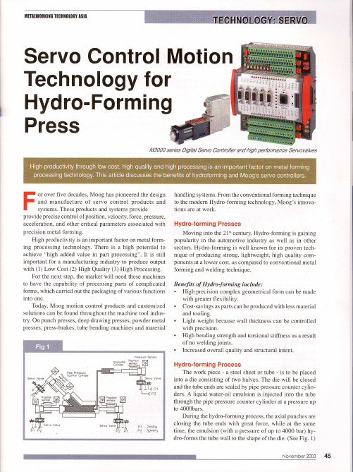
Hydro-forming Presses
Moving into the 21't century,Hydro-forming is gaining popularity in the automotive industry as well as in other sectors.Hydro-forming is well known for its proven technique of producing strong,Iightweight,high quality componentsat a lower cost, as comparedto conventional metal forming and welding technique. B enefits of Hydro-forming include : . High precision complex geometrical form can be made with greater flexibility. . Cost-savingsasparts can be producedwith lessmaterial and tooling. . Light weight because wall thicknesscan be controlled with precision. . High bending strengthand torsional stiffness as a result of no welding joints. . Increasedoverall quality and structural intent.
-N*9ngsI*2Qq9
ห้องสมุดไป่ตู้
45
Very advanced technology is required to achieve the desiredoutput. Complexities can arise such as complicated form, friction power between the mould and product at fabrication, varying swelling rate with different material etc. We use servo control technology to produce the end product with the required thickness, by controlling water pressure or velocity control of each cylinder. This can be achieved by varying.the moving time with the use of control software.
机加工精度要求 英文

机加工精度要求英文Machining accuracy is a crucial aspect in the manufacturing industry, as it directly affects the quality, performance, and durability of the final product. The precision with which a part is machined determines its fitness for use and its ability to meet design specifications. Therefore, it is essential to understand and control machining accuracy to ensure the consistency and reliability of manufactured components.Machining accuracy requirements vary depending on the application and the type of material being machined. For example, high-precision machining is required for components in the aerospace, medical, and automotive industries, where parts must meet strict tolerances and performance standards. On the other hand, lower precision may be acceptable for certain applications where the parts do not require as much accuracy.To achieve the desired machining accuracy, it isnecessary to consider several factors, including machinetool precision, cutting tool selection, workpiece material, and machining processes. Machine tool precision is influenced by factors such as machine rigidity, thermal stability, and vibration control. Cutting tool selection involves choosing the appropriate tool material, geometry, and coating to match the workpiece material and machining conditions. Workpiece material properties, such as hardness, ductility, and thermal conductivity, also affect machining accuracy.Machining processes, such as turning, milling, drilling, and grinding, each have their own unique challenges and considerations. For example, turning is typically used for cylindrical parts and requires precise control of feed rate, spindle speed, and cutting depth to achieve the desired surface finish and dimensional accuracy. Milling, on the other hand, is suitable for flat and contoured surfaces and requires careful selection of cutting conditions to avoid tool wear and maintain dimensional stability.To ensure machining accuracy, it is important toimplement quality control measures throughout the manufacturing process. This includes regular machine tool maintenance and calibration, inspection of workpieces before and after machining, and the use of precision measuring equipment. Additionally, it is beneficial to employ advanced machining technologies, such as CNC machining and additive manufacturing, which provide greater control and repeatability.In conclusion, machining accuracy requirements are critical for ensuring the quality and performance of manufactured components. By considering machine tool precision, cutting tool selection, workpiece material, and machining processes, as well as implementing qualitycontrol measures, manufacturers can achieve the desired machining accuracy and produce reliable parts that meet design specifications.。
钳工凹凸工艺流程
钳工凹凸工艺流程The process of sheet metal forming in the fabrication of components plays a crucial role in the production of high-quality products. 钳工凹凸工艺流程在金属零件加工中起着至关重要的作用。
From cutting and bending to shaping and assembling, every step in the process requires precision and expertise. 从切割和弯曲到成型和组装,每一个步骤都需要精准和专业知识。
The skill of the artisan, combined with the right tools and techniques, is essential in achieving the desired outcome. 工匠的技术,配合适当的工具和技术,对于实现预期的结果至关重要。
One of the key factors in the success of the sheet metal forming process is the design of the component. 钣金加工过程成功的一个关键因素是零件的设计。
The layout and dimensions of the part must be carefully considered to ensure that it can be formed accurately and efficiently. 零件的布局和尺寸必须经过仔细考虑,以确保能够准确高效地成形。
Additionally, the material of the sheet metal must be chosen based on the requirements of the final product. 此外,钣金的材质必须根据最终产品的要求进行选择。
德拉特克 ultima tecnica mini bend 2 cnc 冲床 使用手册说明书
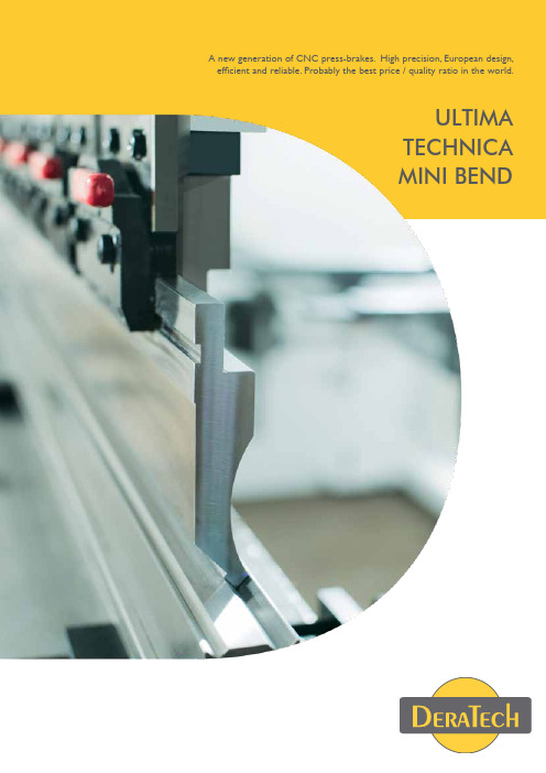
A new generation of CNC press-brakes. High precision, European design, efficient and reliable. Probably the best price / quality ratio in the world.ULTIMATECHNICAMINI BENDPROBABLY THE BEST PRICE/QUALITY RATIO IN THE WORLD!DERATECH Company IntroductionDERATECH GROUPDeratech is specialized in designing and manufacturing sheet metal working machines. T he D eratech headquarters for research, design and assembly are based in Belgium. Subsidiaries all over the world (Australia, China, Germany, Netherlands, T hailand,... ) and carefully selected p artners provide a world class advice, sales installation and service.Shanghai Deratech CNC Machine T ool Co. Ltd, is the new production & technology center of Deratech - Belgium in China. The advanced European design, quality and technology of our R&D center in Belgium together the experienced engineering team of Shanghai Deratech will result in high quality production of sheet metal working machinery. All processing is designed in 3D by our technical department to obtain a high precision on all the manufactured machine parts.Deratech is your partner in sheet metal working machinery.NEXT GENERATION ULTIMA HYBRID CNCPRESS BRAKEThe Ultima hybrid is a new generation of press brake,powered by AC servo motors and variable speed pumps.The Ultima Hybrid is a fast,precise,energy saving and environmentally friendly state of the art press brake.De Ultima Hybrid can save up to 60% energy in contrast to a standard Ultima in same execution, this without losing any speed or production capacity.T here will be only a little energy consumption when the machine is idle,only from the operator pushes the foot pedaltill the upper beam is back in the up position the motors will be powered on and will use energy. So no flows of oil to the tank when the machine is idle,resulting in not heating the oil.The flow rate of the hydraulic pump operates proportionally to the drive speedof the electric motor.The CNC controller transfers the pressure/volume flow target values to the control during the running operation,system pressure is measured by a pressure transducer and is also sent to the servo controller.Based on the control deviation,the built-in PID controller calculates the required motor speed and adapts it accordingly to the existing system requirements of flow rate and pressure.Deratech Ultima Hybrid in std.execution:Yl-Y2,X,R,V with T ouch Screen controller.As option the Hybrid can be equipped with Z1-Z2,X3,X1-X2/R1-R2/Z1-Z2,CNC bending aid, automatic sheet thickness measuring,angle measuring....Invest in the future now.Due to increasing energy casts,variable speed pump machines solutions are on the rise...with energy savings between 30% and 60%...Reliability of powerful hydraulics,as well as energy efficiency and dynamics of compact electronics play hand in hand with the variablespeed pumps.EnergysavingGreenT echnologyHighefficiencyLownoiseUBB HYBRID CNC PRESS BRAKEPRODUCT FEATURES 12UBBHYBRID CNC PRESS BRAKEHigh precision mechanical crowning deviceA Precision quick-clamping device:set-up fast and convenient,reduce labor intensity and improve production efficiency.3High precision and stable backgauge systemsUnique dual linear guide rail structure,ensuring excellentpositioning accuracy.Design of multistage gear,increase thepositioning range,excellent value.4Patented throat distortion compensationdevicePrecise measured amount of distortion and feedback,ensurethat the bending precision.And can effectively prevent thenon-standard collision linear scale of the workpiece.5High precision mechanical crowning deviceHigh-precision wedge compensation device by CNC control,got the precise compensation,ensuring high quality bendingaccuracy.6Moveable front support systemto help you to bend,make a comfortable and efficientworking7A NEW GENERATION OF CNCPRESS-BRAKES. HIGH PRECISION, EUROPEAN DESIGN,EFFICIENT AND RELIABLE.Ultima is a precision CNC-controlled press brake with hydraulic crowning in a basic but very complete configuration.The Ultima is equipped with 5 CNC-controlled axes (Yl-Y2,X,R,V).Ultima offers the user a heavily built,reliable,precision CNC press brake at an economical price.Optional up to 11 CNC-controlled axis.The high precision digital encoders at both sides of the machine continuously measure the m ovement and position of the upper beam (axes Yl-Y2).The data is processed and monitored by the CNC controller which controls the hydraulic valves.An extremely high level of accuracy is obtained during the movement and final positioning of the upper beam due to the continuous monitoring and feedback of the encoder measuring ing this technology,a repeatability of approximately 100% (+/- 0.01 mm) can be guaranteed.The synchro system permits two or more machines to be connected together in tandem to p rovide working lengths of 20 meters or longer.In this tandem configuration,the individual machines can still be used separately.HYDRAULIC PRESS BRAKESThe ESA 650 is a 2D/3D graphical Windows-basedc ontroller with a 17 or optional 19-inch T ouch Screen. Programming the machine is made fast and easy, within seconds the operator is able to bend a high quality part.Make the best of any 3D cad cam you would like to install in the CNC. Direct import of tools shapes (.dxf files) and management of tool library.The powerful built-in Pc allows having on the machine a real 3D cad cam (metallix, radan, esa) Finger-tip work piece design.1A heavily built, rigid, precision backgauge on ball screws with linear guiding insures fast and precise positioning. Adjustment in width is on a precision linear guide way.2Front support arms on a linear guide ensure optimum product support during bending.3PRODUCTFEATURESErgonomic rotating arm for CNC controller Reasonable radius of rotation, more flexible easier operation.5Precision digital encoders at both ends of the machine ensure highly accurate positioning of the upper beam.The independently mounted encoder mounting frames auto-matically compensate for the minimal deflection of the press brake side frames, ensuring perfect bending results. The rama ccuracy is guaranteed to +/-0.0lmm. Bending is a physical process subject to significant elastic d eflection (springback) and can be influenced by many factors. Due to the elastic deformation from both the upper and lower beams of the press brake during the bending process, the bending angle is not constant over the entire bending(plate)length. The CNC- controlled hydraulic crowning device compensates for is defor-mation so an equal bending angle is obtained over the full bending length.4T ool and die holders’ management.Material Data Base or predictive compensation is available as an option.Dynamic crowning is available to grant the perfect bend linearity.Angle measurement and Sheet thickness measuring.HYDRAULIC PRESS BRAKESHigh quality German hydraulic system with highf requency positioning valves. Smooth running of the machine is achieved with high speed machine operation.6Hydraulic tank made of special oil corrosion resistant materials, insuring a perfect clean hydraulic system.7DERATECH patented clean hydraulic systemAccording to our experience in after sales service, 85% of the problems with the hydraulic system are caused by contamination of hydraulic circuit. Deratech has committed to reduce such failures and resolve this from the source by implementation of our patented clean hydraulic system.HYDRAULIC PRESS BRAKESThe CNC-controlled bending aid from Deratech is preventing angle deviations during the bending of thin sheets with large dimensions.The HEAVY -DUTY version is capable to handIe heavy sheet weights.Handling large plates is often not an easy job for one operator, especially with the return movement of the upper beam. In the return movement, the plate is completely loose and the operator has to handIe the full weight of the sheet, it’s resulting that sometimes two people are working on one machine. The Deratech bending aid is a much more efficient and both ergonomic solutions.BENDING AIDHYDRAULIC PRESS BRAKESThe ESA650 is graphical controllers, available both in 2D or 3D. The 17 or 19 inch touch screen control guides you through clear, easy to understand, programming phases. A bending program is drawn within seconds with simulations of the bending process in 2 and/ or 3D. The operator only needs to put the right tools to be ready to bend. Experience tells us, average time from program to production takes less than 1minute! T he controller is fitted with an ETHERNET UTP network connection as standard.CONTROLLERCYBTOUCH-12 CNC system is the update version of famous system DNC880S, powerful and easy-to-use 15 inches touch screen. According to the software, CYBTOUCH-12 can control CNC hydraulic press brake and torsion bar press brake.Modern and ergonomic design, user friendly HMI with a powerful performance.Delem 66T CNC controllers, available in 2D and 3D. A bending program is drawn within seconds with simulations of the bending process in 2 and/ or 3D. The operator only needs to put the right tools to be ready to bend. Experience tells us, average time from program to production takes less than 1 minute! The controller isfitted with an ETHERNET UTP network connection as standard.D-Remote Assistance is a feature of the ESA65O, that allows a D eratech technician to temporarily log-on to the controller of the m achine over a network or internet. This to provide help or resolve issues without directly touching the machine. This feature is simple to set-up, secure and only taking a few moments for our engineer to c onnect and begin the support session, resulting in time and cost saving solution for the end-user.REMOTE ASSISTANCEHYDRAULIC PRESS BRAKESBackgauges1. 5-axis backgauge X-R-Z1-Z2-X’2. 6- axis backgauge X1-X2-R1-R2-Z1-Z23. Backgauge with pneumatic brush support for thin sheetBACKGAUGEFRONT SUPPORTFront Support1. Front support ram on linear guide with parking places and fast height-adjustment.2. Heavy duty front arms on linear rail.3. Custom made front support arms with CNC height controlHYDRAULIC PRESS BRAKES20SHEET THICKNESS MEASURING DEVICEAutomatic Sheet Measuring The “D-STM” sheet thickness measuring system is integrated in the backgauge finger. The D-STM measures the sheet thickness to an accuracy of +-0,0lmm, applicable up to 20mm of material thickness. Them easuring cycle takes only tenths of a second, the measured data will be sent in real time to the CNC and the bending program will be adjusted.21ULTIMAHYDRAULIC PRESS BRAKESD-AlphaD-Alpha angle measurement system a fully automatic, laser-assisted bend angle measure- ment system. irrespective of the properties such as spring back or lamination direction from the material as well as tolerances from the thickness of the material, the D-Alpha enables an exact determination of the bend angle with an accuracy of better than 0,1°. The position of the sensors along the bending line need to be adjusted manually.TOOLINGTOOLING1. Manual fast clamping with eccentric handIe2. Pneumatic fast clamping3. Hydraulic fast clamping4. Manual or pneumatic quick release clamps with vertical tool changePOSSIBILITIESBigger daylight-opening Bigger strokeBigger throat depth22CUSTOM MADE MACHINEOur experienced engineers can design customized features and functions according to customer’s product and require-ments, the maximum to meet customer’s requirements, to help customers improve efficiency and productivity. 23lf you need more product specification please contact with us.REMARK: Other capacities up to 1250 ton or other technical specifications are available upon request.DERATECH ULTIMA (2016)ModelForce (kN)Max. bending length (mm)Distance between uprights (mm)Open-ing height (mm)Throat depth (mm)Cylinder stroke (mm)Main power (kW)Oil volume (L)Speed (mm/s)Dimensions(mm)Weight (kg)Appro-aching speedWorking speedReturning speedLength Width Height UAD-80/2500800250020004403002507,5300200101653080178025506500UAD-100/25001000250020004404002507,5300200101653470185026507600UAD-100/32001000320027004404002507,5300200101654170185026508600UAD-100/41001000410036004404002507,53002001016550701850265010200UAD-130/250013002500200044040025011300200101653480190026707800UAD-130/320013003200270044040025011300200101654180190026708800UAD-130/4100130041003600440400250113002001016550801900267010400UAD-130/5100130051004600440400250114002001016560801900277014800UAD-130/6100130061005600440400250114002001016570801900277017200UAD-170/250017002500200044040025015300200101653500190026809000UAD-170/3200170032002700440400250153002001016542001900268010400UAD-170/4100170041003600440400250153002001016551001900268012200UAD-170/5100170051004600440400250154002001016561001960279016900UAD-170/6100170061005600440400250154002001016571001960279020200UAD-250/250025002500200044040025018,54602001016035202070286012400UAD-250/320025003200270044040025018,54602001016042202070286014300UAD-250/410025004100360044040025018,54602001016051202070286016600UAD-250/510025005100460044040025018,54602001016061202070290020400UAD-250/610025006100560044040025018,54602001016071202070305024600UAD-320/3200320032002700490400300226002001016042402150315018100UAD-320/4100320041003600490400300226002001016051402150315021400UAD-320/5100320051004600490400300226002001016061402190345026300UAD-320/610032006100560049040030022600200101607140219035503120024T echnica is a precision CNC-controlled press brake with crowning in a basic but very complete configuration, equipped with 4 CNC-controlled axes (Yl-Y2, X, V).T echnica offers the user a heavily built, reliable, precision CNC press brake at ane conomical price. The high precision digital encoders at bath sides of the machinec ontinuously measure the movement and position of the upper beam (axes Yl-Y2). The data is processed and monitored by the CNC controller which controls theh ydraulic valves. An extremely high level of accuracy is obtained during the movement and fin alp ositioning of the upper beam due to the continuous monitoring and feedback of the encoder measuring data. Using this technology, a repeatability of approximately 100% (+/- 0.01 mm) can be guaranteed.The synchro system permits two or more machines to be connected together int andem to provide working lengths of 20 meters or longer. A NEW GENERATION OF CNC PRESS-BRAKES. HIGH PRECISION, EUROPEAN DESIGN, EFFICIENT AND RELIABLE.25HYDRAULIC PRESS BRAKES26High precision and fast clamping system:Fast and easy to change the tooling, decreasing labour strength and enhance productivity.1High precision and stable backgauge system:New and unique double linear guide construction, to ensure the excellent positioning accuracy.Design of multistage stops, to increase the Positioning Range.2Precision digital encoders at both ends of the machine ensure highly accurate positioning of the upper beam. The independently mounted encoder mounting frames automatically compensate for the minimal deflection of the press brake side frames, ensuring perfect bending results. The ram accuracy is guaranteed to +/-0.0lmm. Bending is a physical process subject to significant elastic deflection(springback) and can be influenced by many factors.3PRODUCTFEATURES27HYDRAULIC PRESS BRAKESFront support arms on a linear guide ensure optimum product support during bending.5Due to the elastic deformation from both the upper and lower beams of the press brake during the ben ding p rocess, the bending angle is not constant over the entire bending(plate)length. The CNC-controlled crowning device com-pensates for is deformation so an equal bending angle is obtained over the full bending length.428High quality press brake tooling: Durable, fully hardened high precision CNC Press Brake T ooling.6PRODUCT FEATURES29HYDRAULIC PRESS BRAKESUnique technical characteristicsHigh quality German Hydraulic System: High frequency hydraulic system, low failure rate, fast stable and reliable.7High quality Stainless Steel Hydraulic T ank aids in the eliminating contamination8* is no crowning systemTECHNICA(2016)ModelForce (kN)Max. bending length (mm)Distance between uprights (mm)Throat depth (mm)Cylinder stroke (mm)Opening height (mm)Main power (kW)Oil volume (L)Max Speed (mm/s)Dimensions(mm)Weight (kg)Appro-aching speedWorking speedReturning speedLength Width Height 3031ESA 6302D graphic editing for punches and dies. 2D graphic preview for part pieces.Programming of the axes position in tabular mode with automatic calculation of the R and A position and of the bending and crowning tonnage.T ouch Screen 10”Can manage up to 4 axis + 1 and tandem operationESA 630ESA 6402D graphic editing for punches and dies. 2D graphic preview for part pieces.Programming of the axes position in tabular mode with auto-matic calculation of the R and A position and of the bending and crowning tonnage. T ouch Screen 15”Can manage up to all possible axis + 1 tandem operation 3D Viewer functionalityESA 64032HIGH TONNAGE AND LARGEBENDING LENGTH33ULTIMA-UAMHEAVY DUTY PRESS BRAKES34P1P2 Servo controlled table, to easy complete small bends,Using different V-openings in a die. Accurate positioning and reduced tool changesADDITIONAL FEATURES35DERATECH ULTIMA-UAM (2018)lf you need more product specification please contact with us.REMARK: Deratech Group can build pressbrakes up to 1500ton pressing force,this on customer request.ModelNominal pressure (kN) Max. bending width (mm)Distance between uprights (mm)Throat depth (mm)Cylinder stroke (mm)Opening height (mm)Main power (kW)Speed (mm/s)Dimensions(mm)Weight (kg)Approach-ing speedWorking speedReturning speedLength Width Height36The Ultima Minibend is a good example of efficient interaction between operator and machine. By proving the best working conditions to the operator and creating a user friendly environment, will result in outstanding productivity at every stage of the job.The Ultima Minibend is ergonomically designed: movable foot pedal, pivoting control panel, seated or semi-seated operation...The machine frame can be designed to the ergonomic needs of the operator, this to achieve the best possible working conditions in any application possible.The Ultima Minibend is engineered to produce parts commonly found in the production of e lectrical equipment, medical instruments, vending machines,... this is a fast and cost effectively way.MINIBENDCNC PRESS BRAKE37MINIBEND CNC PRESS BRAKE38The ESA 650 is a 2D / 3D graphical Windows-based controller with a 17 or 19 inch T ouch Screen. Program-ming the machine is made fast and easy, within seconds the operator is able to bend a high quality part.1The Ultima Minibend is a single cylinder hydraulic pressbrake, especially designed torsionally stiff welded machine frame, upper beam guided by high precision linear guides for the production of small parts in the productive way possible. Available in b ending length of 1020mm and bending force of 30ton. Backgauge X/R is CNC-controlled and manual finger adjustment.2Green technology, energy saving systemPRODUCT FEATURESULTIMA-MINIBEND (2018)ModelForce (kN)Max. bending length (mm)Distance between uprights (mm)Throat depth (mm)Cylinder stroke (mm)Openingheight (mm)Main power (kW)Oil volume (L)Speed (mm/s)Dimensions(mm)Weight (kg)Appro-aching speedWorking speedReturning speedLengthWidthHeightTAM-35/105035010509002001604104140200152001650145023502750TAM-40/1500400150012003001604105,520020010165245014502370430039A heavily built, rigid, precision backgauge on ball screws with lin-ear guiding insures fast and precise positioning. Adjustment in width is on a precision linear guide way. Option for 4-axis backgauge X-R-Zl-Z2 or more...3D-Remote Assistance is a feature of the ESA 650, that allows aD eratech technician to temporarily log-on to the controller of the machine over a network or internet. This to provide help or resolve issues without directly touching the machine. This feature is simple to set-up, secure and only taking a few moments for our engineer to connect and begin the support session, resulting in time and cost saving solution for the end-user.4MINIBEND CNC PRESS BRAKEManual fast clamping with vertical tool change.5。
YC橡套电缆技术参数
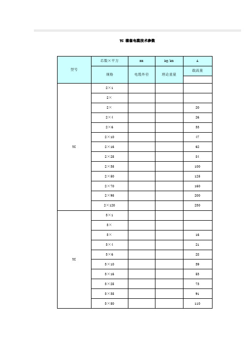
YC 橡套电缆技术参数用途:本产品用于交流额定电压Uo/U 450/750V及以下动力,家用电器及各种移动或电气设备和工具用。
二、性能:(一)通用橡套软电缆:1、产品依据GB5023-1997及JB8735-1998标准。
2、电缆长期允许工作温度应不超过65℃;3、W型派生电缆具有耐气候和一定的耐油性能,适宜于在户外或接触油污的场合使用;(二)电焊机电缆:1、产品依据GB5023-1997标准;2、电缆的长期允许工作温度应不超过65℃;3、成品电缆应经受表A规定的交流50Hz浸水电压实验;4、成品电缆应经受表B规定的交流50Hz浸水电压实验;5、成品电缆应经受表C规定的静态曲线实验。
表A表B表C(三)橡套电缆的型号名称橡套电缆的生产范围:注:根据用户需要,还可生产以上规格外的产品(四)通用橡套软电缆长期允许载流量??????导线工作温度:65℃环境温度:25℃1~26/35kV塑料绝缘高阻燃(隔氧层)电力电缆Plastic Insulated High Performance Flame-retardant Power Cable产品标准 Standard本产品按GB12706-91《额定电压35KV及以下铜芯、铝芯塑料绝缘电力电缆》、《电线电缆成束燃烧试验》、GB/T17650-1998《取自电缆或光缆的材料燃烧时释出气体的试验方法》和GB/T17651-1998《电缆或光缆在特定条件下燃烧的烟密度测定》标准生产1kv~26/35kv塑料绝缘电力电缆,同时还可根据用户需要按国际电工委员会推荐标准IEC、英国标准、德国标准及美国标准生产。
The product is manufactured according to the standard of GB12706-91、、GB/T17650-1998 and GB/T17651-1998 or IEC and DIN and ICEA.适用范围 Applications本产品适用于工频额定电压1kv~26/35KV 输配电线路作配送电能之用。
冲压模具中英文对照

冲压模具中英文对照Stamping die is a key component in the stamping process, and it plays a crucial role in shaping metal sheets into desired forms. 冲压模具是冲压工艺中的关键组件,它在将金属板材成形为所需形状中发挥着至关重要的作用。
Stamping die is commonly used in various industries such as automotive, aerospace, electronics, and construction. 冲压模具通常被广泛应用于汽车、航空航天、电子和建筑等各个行业。
The design and manufacturing of stamping die require high precisionand expertise. 冲压模具的设计和制造需要高度的精密度和专业知识。
The quality of stamping die directly affects the quality and efficiency of the stamping process. 冲压模具的质量直接影响了冲压过程的质量和效率。
Therefore, it is important to understand the characteristics and functions of stamping die in order to produce high-quality products. 因此,了解冲压模具的特点和功能对于生产高质量产品是非常重要的。
Stamping die can be classified into various types based on their functions, such as blanking die, piercing die, bending die, and progressive die. 根据其功能,冲压模具可以被分类为各种类型,如剪床模、冲孔模、弯曲模和级进模。
AD-R Press Brakes SERIES The Winning Force说明书
The Winning ForceThe Winning ForceAs a total supplier for sheet metal manufacturing with almost60 years of experience, Durma understands and recognizes thechallenges, requirements and expectations of the industry.We strive to satisfy the ever higher demands of our customers bycontinuously improving our products and processes whileresearching and implementing the latest technologies.In our three production plants with a total of 150.000 m²,we dedicate 1,000 employees to delivering high qualitymanufacturing solutions at the best performance-to-price ratioin the market.From the innovations developed at our Research & DevelopmentCenter to the technical support given by our worldwidedistributors, we all have one common mission: to be yourpreferred partner.Present Durmazlar machines with name to the world.High technology,modern productionlinesHigh qualitymachines designedin R&D CentreTop qualitycomponents123The Winning ForceWith simple programmable features the high speed AD-R Series press brake adds value to your business with low energy consumption, precision bending and maintenance-free structure.This series can be used safely for many years and simplifies the operators work load.With DURMA press brakes, you always get great results.Fast, productive and perfect bendingAlways precision bending resultsMinimized tool exchange and setting timeMaximized speed and securityAD-R Series Press BrakesAdvance Your StandardsWorld leader in its categoryWhy DURMA Press BrakesEasy to UseFastEfficient Ergonomic Reliable BrandPerfectly equipped for sensitive bending, energy efficient solutionsWith its easy to use control units, rigid body frame, perfect design, high efficiency, multiple tool usage solutions, top level CE safety standards and with its suitable price range, AD-R is the World leader in its category.Better and faster bendingStronger and rigid body structure High sensitivity and repeatability Latest technology Low service cost ReliabilityWith its Performance and Price ratio it is the best CNC Press Brake in the WorldAD-R series press brakes give excellent results of various type business types. It provides a convenient workspace for bends in many different sizes with a longer daylight.Gain More PowerCNC Back GaugeCE Safety System DT-15 Touch Screen Control UnitTop BeamLED Illumination Crowning SystemHydraulic SystemFront Support ArmsTool Holder SystemStrong Back Gauge SystemWhy DURMA Back Gauge ?Most important feature toachieve perfect bending is the stability and the design of the back gauge, which allows an impeccable and correct product to be produced.The high speed ballscrew back gauge system movement is also supported with linear guides,which helps the back gauge achieve long life, greater sensitivity and strengthens against any collisions.Special designed finger blocks with steps to achieve maximum stability can also be supplied for every kind of bending solution.Standard back gauge (X CNC, R manual)CNC optional back gauge RZ1, Z2XZ1RR XZ2XZ1RRXZ2Precise Reliable StrongFast and high accuracy Safe movementAdjustment availability at every point Resistance to crash Maintenance freeHigh sensitivity, Stress relieved steel construction body, long life Mono Block Frame DURMA designed and copyrighted guiding systemBall Screw and linear guide integrated perfect back gauge systemDurable, long life and sensitive bending capability with special hardened top tools Suitable for segmented tools special and fast tool holding system Sensitive solutions on long and deep bending High accuracy linear scales CE safety standardsEnvironmentally friendly ,efficient and perfect bending combinationsGeneral SpecificationsDURMA Multi V Bottom ToolDURMA Top ToolQuick Release ClampingTool Holders and ToolsEuropean Type Bottom Tool (4V Die)European Clamping SystemManual or CNC-controlled motorized crowning system simplifies bending, by adjusting each point of the bending parts to acquire straight bends. The need for shimming is eliminated.Crowning SystemCNC Crowning SystemOur machines are designed in accordance with Ce-Norms to ensure your safety with hydraulic, electric, appropriate height covers and laser light curtains.CE safety in tandem machines are also provided with light barriersCE Safety SystemsBy using long and planar guiding surfaces, all the disadvantagesof point guiding are eliminated 100%. free bendingspace: guiding system that eliminates bending between frame has been moved to the outside of the frame.Stable Top Beam MovementLinear Guide Front Sheet SupportsRugged support arms with tilting stops are mountedon a linear guide rail system. This allows “finger-tip” lateral adjustment as required by the bend length of the part. They are also equipped with side gauges for the fast, easy, and accurate feeding of parts small or large.Linear Guide Front Sheet SupportsBending performance increased using with high quality European clamping system and easy to use. Narrow table designed for European style tool holder and Z bending. DURMA is your solution partner with various tool options.Safe and Accurate Bends with Top Quality EquipmentsModEva 19T15" color Touch ScreenOn-screen finger profile drawing Automatic bend listingVery simple and convenient data transfer Higher productivity thanks to easy and rapid Multi-simulation capabilitySimulation criteria for better sheet management Windows XPe for multitasking and file management EC safety-cycle management Ethernet for Easy communication Bundled Offline Software 15” color Touch SchreenDT-15 Control UnitDURMA TouchOptional Control Units InterfaceDA-66TEverything is UnderControl with User-FriendlyD-Bend offline softwareD-Bend Offline software allows you to simulate your bending at your desk in your office.Youcan create your tools and it provides the opportunity to make new programs without interrupting production. D-Bend verifies your bend sequence. Creates verified part drawings for Laser, punch, and plasma machines.Create profile with touch screen Online service via Internet connectionDiagnostic modeEasy programming pageAutomatic bend calculation and listingTool programming and libraryAutomatic bend listing Storing your programs Easy bend functioning2D color graphics display and multiple simulation Linux operating system D-Bend offline software Tandem compatibleMultiple language options Ergonomic panel designUSB port, back-up 10 "TFT color touch screenDA-58T2D graphical touch screen programming 15" high resolution colour TFT Bend sequence calculation Crowning controlServo and frequency inverter controlAdvanced Y-axis control algorithms for closed-loop as well as open-loop valvesUSB, peripheral interfacingConsultancy Spare PartsR&D CenterServiceAgreementsTrainingAfter Sales ServiceSoftware Flexible SolutionSolution CenterDURMA provides the best level of service and spare parts with qualified personnel and spare parts in stock.Our experienced and professional service personnel are always ready at your service. Our professional training and application enriched courses will give you an advantage to use our machinery.Fast on Service and Spare PartsStandard EquipmentsY1, Y2, X=650mm (AL - double gayt )Control Unit - CNC DT15 Touch screen 2D graphic (Remote Control)Back gauge - motorised & linear guide & ball bearing system Manually adjustable R axes European Clamping systemSliding sheet support Arms with T-Channel and Tilting stop Special designed – world-class hydraulics blocks & valves World-class electrical equipment Manuel crowningOptional EquipmentsControl Unit - CNC ModEva 19T 3D Colour Graphic Control Unit - CNC DA 58TCE with FIESSLER AKAS-LC II F manual + AKFR control box CE BLVT safety – only for tandem machines Motorized R Axes Z1 - Z2 axes CNCDBEND 3D CAD/CAM Importing & Similation Program European style top tool European style bottom tool Bottom tool DurmaQuick Release ClampingCNC controlled Motorized CrowningBack gauge 1000 mm - Back protection with Light barrier Oil CoolerAdditional Finger blocks & Sliding front arms Overseas special packagingStandard & Optional Equipment* 750 mm throat depth** 750 - 1000 - 1250 mm throat depth *** 500mm/sec. backgauge speed on AL. Machines set according to optimum values.AD-R Serisi Teknik DetaylarS : Standard O : OptionDurmazlar Makina San. ve Tic. A.Ş.OSB 75. Yıl Bulvarı Nilüfer-Bursa / Türkiye P: +90 224 219 18 00 F: +90 224 242 75 80******************.tr .trEN_2018/05/V05。
产品手册(中英对照)
公司产品定位于国内外钢材市场急需的汽车板、家电板和高档建筑板,年生产规模为150万吨,其中冷轧连续退火产品70万吨,热镀锌产品80万吨。成品具有规格多、宽度大、表面光洁、钢质纯净、板形平直、性能稳定等特点。
The enterprise productsis going to serve for manufacturing of automobile, household appliance and high level building plate which are needed eagerly in steel market all over the world, the total production capacity is 1.5 million tons per year, including 0.7 million tons Annealed coldrollingstrips and 0.8 million tons Hot-dip galvanized strips. There are many advantages of our products like abundantsizes, broad widths, clean surface, pure steel, flat shape,stablemechanical propertiesand so on.
封面文字(外)
产品手册PRODUCTS MANUAL
北京首钢冷轧薄板有限公司BEIJING SHOUGANG COLD ROLLING CO.,LTD.
封面文字(内)
公司概况INTROห้องสมุดไป่ตู้UCTION
优秀的品质…EXCELLENT QUALITY…
更高的效率…MORE EFFICIENT…
管材弯曲件的微弯加工工艺流程
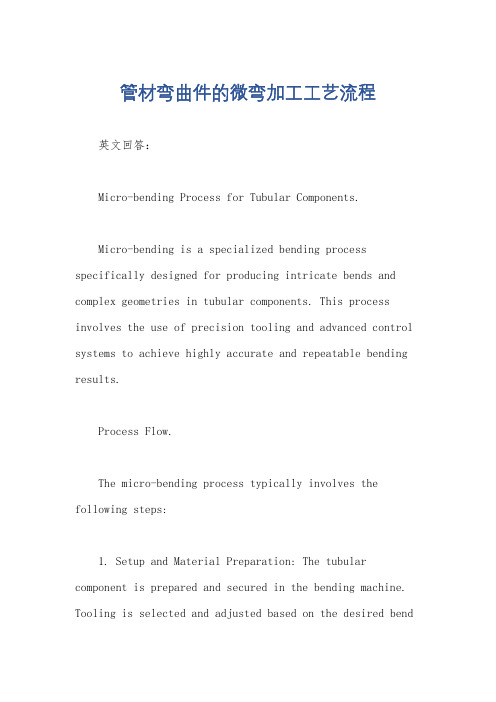
管材弯曲件的微弯加工工艺流程英文回答:Micro-bending Process for Tubular Components.Micro-bending is a specialized bending process specifically designed for producing intricate bends and complex geometries in tubular components. This process involves the use of precision tooling and advanced control systems to achieve highly accurate and repeatable bending results.Process Flow.The micro-bending process typically involves the following steps:1. Setup and Material Preparation: The tubular component is prepared and secured in the bending machine. Tooling is selected and adjusted based on the desired bendradius and geometry.2. Axial Feeding: The tubular component is gradually fed into the bending machine along the bending axis, using a precision linear actuator.3. Radial Bending: The bending head applies acontrolled force to the tubular component, causing it to bend along the desired radius. The bending head may employ various techniques such as rotary bending, ram bending, or roll bending.4. Continuous Monitoring and Control: Advanced sensors and control systems monitor the bending process in real-time. Adjustments are made to ensure accurate bending and prevent defects.5. Part Removal: The bent tubular component is ejected from the machine and inspected for dimensional accuracy and quality.Benefits of Micro-bending.High Precision and Repeatability.Ability to Handle Small Radii and Complex Geometries.Low Material Deformation and Springback.Reduced Cycle Times.Minimal Operator Intervention.Applications.Micro-bending finds applications in a wide range of industries, including:Automotive and Aerospace.Medical Device Manufacturing.Electronics and Telecom.Appliance and Furniture Production.中文回答:管材弯曲件的微弯加工工艺流程。
利用纳米技术发挥想象英语作文350字

全文分为作者个人简介和正文两个部分:作者个人简介:Hello everyone, I am an author dedicated to creating and sharing high-quality document templates. In this era of information overload, accurate and efficient communication has become especially important. I firmly believe that good communication can build bridges between people, playing an indispensable role in academia, career, and daily life. Therefore, I decided to invest my knowledge and skills into creating valuable documents to help people find inspiration and direction when needed.正文:利用纳米技术发挥想象英语作文350字全文共3篇示例,供读者参考篇1Unleashing Imagination through the Nanotechnology RevolutionEver since I was a kid, I've been fascinated by the idea of shrinking down to a tiny size like the characters in my favoritebooks and movies. Imagine being able to explore the microscopic world, venturing inside the human body or witnessing the inner workings of a computer chip. Well, thanks to the rapidly advancing field of nanotechnology, that fantasy is inching closer to reality every day.Nanotechnology deals with manipulating matter at the atomic and molecular scale - a nanometer is just one-billionth of a meter! At these infinitesimal dimensions, materials exhibit wild and unexpected properties that could revolutionize virtually every aspect of our lives. Imagine underwear that never gets smelly or stained thanks to nanoparticles that destroy bacteria and repel liquids. Or super-strong, paper-thin surfaces that could lead to foldable smartphones and tablets. The possibilities seem limited only by our imagination.One area I find particularly mind-blowing is nanomedicine. Researchers are developing microscopic nanorobots that could one day be injected into our bodies to detect diseases at the earliest stages and directly deliver drugs to diseased cells with unprecedented precision. Some nanoparticles can already cross the blood-brain barrier, opening up new frontiers for treating neurological disorders. In the future, nanobots could even be programmed to repair our bodies from the inside out byrearranging molecules! How cool would it be if we could just replace worn-out body parts cell by cell instead of undergoing major surgery?From vastly more efficient energy production and storage, to ultra-fast computers and unhackable cybersecurity, to asteroid mining and space manufacturing, nanotechnology promises to reshape our world in ways we can scarcely fathom. As a student fascinated by science and technology, I can't wait to see how this incredible field continues to evolve. With brilliant minds unlocking the potential of the unimaginably small, truly anything seems possible. The nano revolution is here - and it's time to think big by going ultra-tiny!篇2Unleashing the Imagination with NanotechnologyThe world of nanotechnology is a realm where the boundaries of imagination are limitless, and the possibilities are vast as the galaxies that adorn the cosmos. As a student of science, I find myself captivated by the sheer potential that this revolutionary field holds, and I cannot help but ponder the myriad ways in which it could reshape our understanding of the universe and our place within it.At its core, nanotechnology is the manipulation of matter at an infinitesimally small scale – a scale so minute that it challenges the very limits of our comprehension. It is a frontier that blurs the lines between the tangible and the theoretical, where the laws of physics take on new dimensions and the very fabric of reality is subject to our tinkering.Imagine, if you will, a world where disease is but a fleeting memory, where microscopic machines coursing through our veins eradicate illness with surgical precision. Envision cities that repair themselves, their structures fortified by self-assembling nanorobots that mend cracks and fissures with effortless grace. Picture a future where energy is abundant, harnessed from the very fabric of the universe itself, where nanogenerators convert the kinetic energy of our footsteps into an inexhaustible power source.But the true wonder of nanotechnology lies not merely in its practical applications but in the boundless realm of imagination it unleashes. As students, we are taught to dream, to push the boundaries of what is possible, and to embrace the unknown with open arms. Nanotechnology is the embodiment of this ethos, a field that challenges us to reimagine the very buildingblocks of existence and to reshape the world around us with molecular precision.Consider, for a moment, the vast expanse of space that stretches endlessly before us. What if we could construct probes no larger than a speck of dust, imbued with the intelligence to traverse the cosmos and unravel the secrets of distant galaxies? Or perhaps we could engineer nanostructures capable of manipulating the fundamental forces of nature, bending the fabric of space-time to our whims and redefining the very boundaries of reality.The potential applications of nanotechnology are limited only by the bounds of our imagination. From revolutionizing medicine and computing to transforming our understanding of the universe itself, this field promises to rewrite the narrative of human existence and propel us into a future that was once the stuff of science fiction.Yet, as we stand on the precipice of this technological revolution, we must also exercise caution and wisdom. With great power comes great responsibility, and it is incumbent upon us as students, as the inheritors of this brave new world, to ensure that nanotechnology is harnessed for the betterment of humanity and the preservation of our fragile planet.We must be vigilant in our pursuit of knowledge, uncompromising in our adherence to ethical principles, and unwavering in our commitment to using these technologies for the greater good. For it is not the tools themselves that shape our destiny, but the wisdom and compassion with which we wield them.As I gaze into the future, I am filled with a profound sense of awe and wonder. The possibilities that nanotechnology presents are vast, and the potential for shaping a better tomorrow is limited only by the boundaries of our imagination. It is a frontier that beckons us to dream, to explore, and to push the boundaries of what is possible.And so, my fellow students, let us embrace this challenge with open hearts and open minds. Let us be the architects of a tomorrow that was once unimaginable, where the impossible becomes reality, and where the limits of human potential are rewritten with each passing day. For in the realm of nanotechnology, the only true boundaries are those we impose upon ourselves.篇3Using Nanotechnology to Unleash Your Imagination (350 words)Hey there! As a student fascinated by science and technology, I can't help but geek out over the incredible potential of nanotechnology. This cutting-edge field allows us to manipulate matter at an incredibly small scale, opening up a world of possibilities that were once confined to the realms of science fiction.Imagine being able to create materials with extraordinary properties, like fabrics that can regulate temperature,self-cleaning surfaces, or even invisible cloaks! With nanotechnology, we can engineer materials at the molecular level, giving us unprecedented control over their characteristics.But the applications of nanotechnology go far beyond just materials science. In the medical field, for instance, we could develop nanorobots capable of navigating the human body and delivering targeted treatments to specific cells or tissues. These tiny machines could revolutionize the way we diagnose and treat diseases, potentially leading to more effective and less invasive therapies.Speaking of tiny machines, how cool would it be to have your own personal nanobot assistant? Imagine having amicroscopic robot that can help you with tasks, take notes, or even act as a personal translator! The possibilities are truly mind-boggling.And let's not forget about the potential impact of nanotechnology on computing and electronics. By manipulating matter at the nanoscale, we could create faster, more efficient, and more powerful devices than ever before. Who knows, we might even be able to develop quantum computers that can solve problems that are currently impossible for classical computers!Of course, with great power comes great responsibility, and we must ensure that nanotechnology is developed and used responsibly. There are legitimate concerns about potential risks, such as the environmental impact and potential misuse of these powerful technologies. But with proper regulation and ethical oversight, I believe that nanotechnology can be a force for good, helping us to solve some of humanity's greatest challenges and unlocking a future that was once unimaginable.So, fellow students, let's embrace our inner scientists and dreamers! Nanotechnology is a field that truly allows us to unleash our imaginations and push the boundaries of what'spossible. Who knows what incredible discoveries and innovations await us in the incredible world of the ultra-small?。
彩钢瓦加工流程
彩钢瓦加工流程Processing of color steel tiles is a crucial step in construction projects. 彩钢瓦加工是建筑项目中关键的一步。
The process involves cutting, bending, and shaping the steel sheets to meet specific design requirements. 这个过程涉及将钢板剪切、弯曲和成型,以满足特定的设计要求。
Each step in the process requires precision and skill to ensure the final product is of high quality. 每个步骤都需要精准和技巧,以确保最终产品具有高质量。
One of the first steps in the processing of color steel tiles is cutting the steel sheets to the required size. 彩钢瓦加工的第一步之一是将钢板切割成所需尺寸。
This step is crucial as it determines the overall dimensions of the final product. 这一步是至关重要的,因为它决定了最终产品的整体尺寸。
Precision cutting is essential to ensure that the steel sheets fit together seamlessly during the assembly process. 精确的切割是必不可少的,以确保在装配过程中钢板能够无缝地拼接在一起。
After the steel sheets are cut to size, the next step in the process is bending the sheets to the required shape. 钢板切割到所需尺寸后,加工流程的下一步是将钢板弯成所需的形状。
BOSS GT-100 下一代COSM电吉他效果器说明书

PREAMPNATURL CLEAN FULL RANGE COMBO CRUNCH STACK CRUNCH HiGAIN STACKPOWER DRIVEEXTREM LEADCORE METALJC-120CLEAN TWINPRO CRUNCHTWEEDDELUX CRUNCHVO DRIVEVO LEADMATCH DRIVEBG LEADBG DRIVEMS1959 IMS1959 I+IIR-FIER VINTAGER-FIER MODERNT-AMP LEADSLDN5150 DRIVEADVANCED VINTAGECUSTOMNewly designed with dual LCD displaysand the latest COSM amps.The pinnacle of the GT series has arrived!Powered by BOSS’s latest custom DSP, the GT-100 delivers mind-bending powerand performance. Welcome to the next generation of COSM!Completely new user interface with dual displays.Quickly and directly control the GT-100’s range of advanced features. New A/B Channel Divide Function Overdub and loop to createinnovative solos and phrasesRecord the high-quality GTsound directly to your DAWa SUB OD/DS feature thatlets you apply differentdistortion types to eachchannel.COSM AMP DUAL LCDGet Creative with the ACCEL Pedal.Step into a New Dimension of Expression!ACCEL PEDALn Example of effect chainThe highly popular EZ Tone function has nowbecome even more powerful!EZ TONEAll specifications and appearances are subject to change without notice.Roland, BOSS, COSM, METAL ZONE and SLICER are either registered trademarks or trademarks of Roland Corporation in the United States and/or other countries.Company names and product names appearing in this document are registered trademarks or trademarks of their respective owners.It is forbidden by law to make an audio recording, video recording, copy or revision of a third party’s copyrighted work (musical work, video work, broadcast, live performance, or other work), whether in whole or in part, and distribute, sell, lease, perform, or broadcast it without the permission of the copyright owner.Do not use this product for purposes that could infringe on a copyright held by a third party.We assume no responsibility whatsoever with regard to any infringements of third-party copyrights arising through your use of this product.Printed in Japan Jan. 2012 RAM-4737 GR-GEN-SS AABE1FootswitchDual FootswitchExpression Pedal。