Corrosion behaviors of Cr-Al-N coatings deposited by reactive magnetron sputtering
The Chemistry of Corrosion

The Chemistry of Corrosion 腐蚀化学腐蚀是指金属在特定条件或环境下失去原有性能的现象。
它经常发生于水、氧气、酸、碱等介质中,引起金属表面发生一定程度的化学变化和极度的脆化。
这是由于金属原先的电位被腐蚀介质作用下,发生氧化还原反应,而失去电子而导致的。
在化学角度上,腐蚀也是一种极不稳定的化学反应。
首先,金属离子的析出是腐蚀的反应过程。
从该反应过程中,金属离子将锈迹进入外界介质,形成了电解质,这将成为腐蚀反应的催化剂。
接下来,随着离子流的出现,金属与外部介质的暴露面积不断增加,导致反应加剧。
这将使更多的金属离子暴露在反应区域内,引发更多的锈迹。
有时候腐蚀反应并不是显而易见,而是在电极-电解质界面上发生得非常微小的化学反应。
这些极微小的反应产生充足的机会,使得一些无害元素或化合物从外部环境中进入区域内。
一旦这些化合物混入了反应区域,它们将催化反应,并促进更多的金属离子溢出,加速腐蚀反应。
有许多类型的腐蚀反应,其中一种最常见的是电化学腐蚀。
这种现象通常发生在由电解质环境和不同电位的金属或合金构成的氧化反应中。
在这种反应中,金属离子向电解质传递电子,以满足电子亏损和在电化学反应中发生氧化还原反应。
这样,金属表面就会发生可见的腐蚀问题。
实际上,除了电化学腐蚀外,还有一些化学反应也会导致金属腐蚀的发生。
例如,金属与强氧化剂接触,或与硫酸等酸性介质发生反应,金属表面就会发生化学反应,从而散发出严重的腐蚀气味。
除了金属氧化反应之外,其他的化学反应也会参与到腐蚀问题中来。
例如,波尔氢离子(H2O)将电子泄漏到金属离子,使其电位降低,从而发生氧化还原反应。
在这样的化学反应中,有很多其他类型的离子和分子也参与其中,包括硝酸根、硝酸离子等化学物质。
在汽车、建筑、电器等行业,金属腐蚀问题经常出现。
不仅会破坏金属材料的结构和性能,而且会造成高昂的维修和替换成本。
因此,在金属腐蚀的防治和缓解方面,化学家们需要不断地进行深入的研究和探索。
-Corrosion_Behaviuor_Of_Stressed_Magnesium_Alloys-Elsevier
Corrosion behaviour of stressedmagnesium alloysP.L.Bonora a ,M.Andrei a,*,A.Eliezer b ,E.M.Gutman baDepartment of Materials Engineering,Laboratory of Industrial Corrosion Control,University of Trento,via Messiano 77,I-38050Trento,ItalybDepartment of Materials Engineering,Ben-Gurion University of the Negev,Beer-Sheva,IsraelReceived 3July 2000;accepted 28May 2001AbstractPotentiodynamic polarisation and impedance measurements are used to examine the cor-rosion aspects of some Mg-based alloys,which were previously stressed in order to established the e ect of mechanical deformation on surface electrochemical reactions.A ®rst approach was made for the unstressed alloys.The electrochemical tests were carried out in a sodium borate bu er solution.Ó2002Elsevier Science Ltd.All rights reserved.Keywords:Mechanochemical e ect;Magnesium alloys;Potentiodynamic polarisation;Electrochemical impedance1.IntroductionThe perception of magnesium as a rapidly corroding material has been a major obstacle to its growth in structural applications despite its other desirable physical properties.More importantly,the problem of stress corrosion is becoming a major one today in Mg alloys.New Mg alloys have been developed in recent years to meet the needs of structural applications.Many cast alloys were tested for stress corrosion cracking and their high sensitivity to stress corrosion was demonstrated [1,2].Some magnesium and magnesium alloys applications,especially in the transportation industry require/locate/corsciCorrosion Science 44(2002)729±749*Corresponding author.Tel.:+39-461-882403;fax:+39-461-881977.E-mail address:andrei@ing.unitn.it (M.Andrei).0010-938X/02/$-see front matter Ó2002Elsevier Science Ltd.All rights reserved.PII:S 0010-938X (01)00101-9730P.L.Bonora et al./Corrosion Science44(2002)729±749good fatigue properties[1].Corrosion fatigue is the simultaneous action of corrosion and alternating stress on an alloy,leading to a lower fatigue limit than in the case of fatigue without any environmental impact.In general,the aim of every stress corrosion study is to develop a basis for quantitative prediction and qualitative diagnostic of the incidence of cracking and failure under impact of environments and stresses.A more realistic way is to separate stress corrosion with in¯uencing signi®cant phenomena and to study these phe-nomena with the hope to develop a more general mechanism in future.Such im-portant phenomena are mechanochemical e ects(MCEs)and creep at crack tip[3].2.Experimental methodIn this work,AM50and AZ91D magnesium alloys were studied.The most common die casting alloy is AZ91D with9%Al content.The combination of¯u-idity,strength and ductility of an alloy with9%Al is undeniably one of the reasons for which AZ91D alloys usage is widespread.Nevertheless,AZ91D has some dis-advantages for use in a die casting.Firstly,although the material has good short-term strength at elevated temperatures,the creep resistance is poor.This has been attributed to the large amount of the presence of low melting eutectic(Mg17Al12). Another disadvantage of higher Al content containing alloys is that ductility is usual sacri®ced to grain strength[4].But Mg alloys having lower Al content,for example AM50(5%Al)were found to be more ductile,especially during impact situation. However,many structural applications require an appreciable amount of energy absorption during their operation[3].Thus,it is essential to study corrosion fatigue resistance of Mg alloys and to investigate the correlation of corrosion fatigue with the mechanochemical behaviour of the Mg alloys.The Mg alloys were submitted to the standard mechanical tests before the electrochemical ones.The behaviour of both stressed and non-stressed magnesium alloys was investigated by using poten-tiodynamic polarisation measurements(DC polarisation)and electrochemical im-pedance spectroscopy(EIS).All the electrochemical measurements were performed in a tetraborate bu er solution that is a stable solution with a pH( 9.7)at which Mg can cover itself with more or less protective oxide or hydroxide which checks the dissolution reaction [5].A very used solution for the corrosion common studies of Mg alloys is NaCl Mg(OH)2with a pH about10.5.This solution does not have a stable pH value in the electrode surface and thus,the corrosion conditions are not stable.In our study the borate solution eliminate this unstable and the undesirable presence of anions ClÀthat even in small amounts,usually break down the protective®lm on Mg[6,10].The electrochemical testing was employed to study the main features of the processes taking place at the alloy/solution interface.The e ect of di erent ap-plied tensile stresses on the Mg-alloy corrosion resistance was studied.The corrosion resistance of Mg alloys was pointed out by EIS measurements performed during the free immersion time and under polarisation and the e ect of the di erent tensile stresses was studied.The evolution of the electrode/electrolyte interface at di erentP.L.Bonora et al./Corrosion Science44(2002)729±749731 immersion times was also studied.The corrosion rate has been calculated by the analysis of the potentiodynamicpolarisation that was c arried out by the linear po-larisation method.The¯at specimens of magnesium alloys(AM50and AZ91D)used for this study were prepared by the casting procedure(t cast 660°C and650°C,respectively). Chemical composition(wt.%)and mechanical properties are given in Tables1and2. The electrochemical tests using both DC(potentiodynamic polarisation)and AC techniques(EIS)were carried out in an aerated0.05M sodium tetraborate solution (pH 9:7).For all measurements a three electrode electrochemical cell was used, with an Ag/AgCl as reference electrode and a platinum counter electrode.The working electrode was prepared from the Mg-alloy samples after the application of the tensile strength.Mg-alloy samples were embedded in an acrylic resin to provide electrical isolation of the sample surface.The samples were air dried at room tem-perature.The potentiodynamicc urves were obtained using a PAR273potentiostat,with a voltage scan rate of0.2mV/s.The impedance measurements were carried out using a Solartron1250frequency response analyser coupled with the potentiostat.All the experiments were controlled by a PC,which was also used for the acquisition, storage and plotting of data.The scanned frequency ranged from6mHz to100kHz and the perturbation amplitude was of5mV(it was observed that a variation of the amplitude did not change the frequency response of the electrode/electrolyte inter-face).The impedance measurements were performed at open circuit potential(E OC) and also under potentiostaticc onditions.Table1Chemical analysis after die casting in wt.%Mg alloy Al Mn Zn Si Cu Fe Ni BeAM50 5.10.5700.0130.00070.00740.00060.0013 AZ91D8.40.170.850.010.00080.00130.00070.0003Table2Mechanical properties of samplesMg alloy TYS a(MPa)UTS(MPa)Elongation(%) AM50Without LoadingAM50120.3125.40.30AM50129.9147.6 1.94AM50131.2152.1 2.13AM50129.9151.7 2.26AM50135.6166.0 3.56AM50118.7160.4 4.39AZ91D Without LoadingAZ91D166.4174.20.29AZ91D166.7180.40.45AZ91D179.2193.70.71a TYS is the tensile yield strength.All the measurements of this study were taken after stabilisation of the open circuit potential,i.e.20min after immersion of the electrode in the solution.All the potential values are reported with respect to the reference electrode (E Ag =AgCl 0:210V versus ENH).3.Results and discussion3.1.Potentiodynamic polarisation measurementsThe potentiodynamicc urves in 0.05M sodium tetraborate solution (pH 9:7)of unstressed Mg alloys and pure Mg are shown in Fig.1.As a ®rst remark we note that the shape of the polarisation curves is almost the same for the two alloys.In addi-tion,a current plateau begins at À1:2and À1:3V for AM50and AZ91D,respec-tively,the current values being quite similar and relatively high.We can assume that the alloy samples present a ``pseudo-passivation'',which di ers with respect to pure magnesium.We also note that by alloying the corrosion potential values become much nobler and the anodic current densities reduce.Figs.2and 3show the potentiodynamicc urves obtained for both Mg alloys as a function of the applied stress.The e ect of mechanical deformation on the corrosion behaviour can be seen.The corrosion parameters estimate the MCE,which means the increasing of the anodic current densities and the disennobeling of the potential values caused by the deformation.The corrosion rate (i corr )was determined for small deviations from the corrosion potential.The obtained values are plotted as a function of strain in the Fig.4.The graphs in Fig.4also contain the corrosion potential values.First of all,we remark that both corrosion current and corrosion potential depend strongly on the applied stress.So,we can note that i corr increases with the elongation up to a value of 1.94%and 0.29%for AM50and AZ91D,respectively.After that,the corrosion currentis732P.L.Bonora et al./Corrosion Science 44(2002)729±749reduced.Thus,the corrosion rate passes over a maximum in relation to the increase in plasticdeformation,ac c ording to the general theory [2].For the same values of the strain for that a maximum value of the corrosion current was obtained,the corrosion potential reaches the most negative values.A signi®cant MCE for both corrosion rate and corrosion potential manifests itself in the magnesium alloys under study.It can be also seen that a new slower increase of i corr is produced at 3.56%and after 0.45%of residual strain for AM50and AZ91D,respectively.Experimental con®rmation of the correlation between the mechanochemical be-haviour and the strain hardening stages (intensive strain hardening and dynamic recovery)could be see in Fig.5,which regroups the stress±strain curves and the corrosion rate variations for both magnesium alloys.The observed correlation could be explained by the change of dislocation substructure during the plastic deforma-tion as was already done in the case of other materials alloys [7].Under intensestrainP.L.Bonora et al./Corrosion Science 44(2002)729±749733hardening,stresses grow and planar dislocation pile-ups appear.This leads to a sharp increase in the MCE.At the ®nal stage of the dynamic recovery,planar pile-ups are destroyed due to dislocation cross-slip and partial annihilation.This leads to a decrease in the MCE value,which,thus,should pass over a maximum in the process of plastic deformation.The MCE should grow intensively under plastic deformation at the stage of strain hardening.In particular,the acceleration of metal anodic dissolution is caused by a local reduction of equilibrium potential in the vicinity of dislocations.This e ect is much lower at the ®nal recovery stage.At this stage,strain hardening is suppressed because of the development of dislocation cross-slip processes.In a previous stress corrosion study [1]a signi®cant mechanoelectrochemical e ect for corrosion rate,anodic current under constant potential and corrosion potential for the di erent Mg alloys in alkaline media (pH 10:5)was already observed.It was also noted that for the AM20and AM50alloys the mechanical e ect show a maximum when the strain hardening stage transfers to the dynamicrec overy stage.It is also important that the features of mechanical behaviour are the same in both active and pseudo-passive states,independently of surface ®lm existence.Thus,the analysis of the potentiodynamic curves was also carried out at the cross-sectionsof734P.L.Bonora et al./Corrosion Science 44(2002)729±749curves at di erent selected potential levels to ®nd the corresponding current densi-ties.The potential levels were chosen in both active and ``pseudo-passive''ranges.The obtained values are plotted in Fig.6.For a better illustration of the MCE,Fig.6also regroups the potential values under constant current densities.All the values are plot as a function of strain.Therefore,it can be seen that the anodic current in-crement and the decrease of potential manifest itself in both active and passive states in the case of AM50alloy.For the AZ91D magnesium alloy,a slight decrease in anodic current and a slow increment of potential are observed in both active and passive states at the beginning of the applied stress,contrary to the corrosion current and potential.The two alloys under study contain the intermetallic compound Mg 17Al 12.A low content of Al leads to a reduced amount of phase Mg 17Al 12[4].It was observed that the b -phase is inert to the chloride solution in comparison to the magnesium matrix and acts as a corrosion barrier depending on the manner that the phase Mg 17Al 12is distributed in the alloy matrix [8].So,the b -phase present in the cast alloy is generally more resistant than the surrounding matrix alloy.Corrosion resistance of the b -phase is related to its passive behaviour within a much wider pH range than its purecomponents.P.L.Bonora et al./Corrosion Science 44(2002)729±749735Corrosion rate measurements of binary alloys showed that Al was the only ele-ment which caused a decrease in the corrosion rate of Mg;the corrosion rate de-creased with increasing Al content [9].Indeed,in our study realised in a free chloride media it was seen that in the non-stressed conditions,the corrosion rate of the alloy with higher Al content is lower than that for the alloy with less Al.This is largely due to the presence and distri-bution of the b -phase (Fig.7a)that better protects in the AZ91D alloy with a higher content of Al and so with an elevated amount of b -phase.For AM50with low Al content,the fraction b -phase is small and is only formed as discrete islands in the structure (Fig.7b).But hard secondary phase promotes strain hardening and thus,increases chemical potential of atoms,i.e.they create the necessary conditions for mechanochemical dissolution [2].Consequently it is expected that most resistance to developing MCE will be obtained for the alloys with highest Al contents.Indeed,deep pitting cor-rosion occurs and the lifetime of the alloy decreases as the amount of b -phase in-creases [10].Our potentiodynamicstudy demonstrated that the AZ91D had high c orrosion rate in deformed state that AM50under stress.In addition,some recentstudies736P.L.Bonora et al./Corrosion Science 44(2002)729±749proved that the highest sensitivity to corrosion creep and corrosion fatigue [11]in a corrosive environment is observed in the alloy with highest Al content.It was also shown that the borate anions act as a corrosion inhibitors at the ®rst stage of creep [10].3.2.Electrochemical impedance spectroscopy measurementsA corroding metal is,as a ®rst approximation,modelled as a simple electro-chemical system consisting of a double-layer capacitance,a solution resistance and a charge transfer resistance.A system like this can be studied by using an AC signal,which can provide more information than a DC polarisation.Thus,applying a 5mV sinusoidal potential through a potentiostatic circuit,the potential±current response plots provide the impedancevalues.P.L.Bonora et al./Corrosion Science 44(2002)729±749737The impedance diagrams are recorded at the initial time (t 0h)immediately after the stabilisation of the steady-state potential.In the present study,EIS measurements were performed at open circuit and also under polarisation.Thus,the typical Nyquist impedance plots showed in Fig.8are obtained for unstressed Mg alloys in the tetraborate solution at free immersion potential and under anodicand cathodicpolarisation.738P.L.Bonora et al./Corrosion Science 44(2002)729±749P.L.Bonora et al./Corrosion Science44(2002)729±749739 The Nyquist plots of both magnesium alloys at open circuit exhibit two capacitive loops,one for high and intermediate frequencies and the other,the small one,for low frequencies.The®rst capacitive loop is attributed at the charge transfer process. Thus,for the frequencies higher than1Hz,a resistor R p and a capacitor C dl in parallel can model the electrode/electrolyte interface.A partial data®tting made with the Boukamp circuit equivalent software[12]for the charge transfer process pro-duced the R p(polarisation resistance)and C dl(double-layer capacitance)values. The R p of the charge transfer process is207.7and374X cm2for unstressed AM50 and AZ91D alloys,respectively.The obtained capacitance values are22.6and 68l FcmÀ2,for AM50and AZ91D,respectively and they are associated at a double-layer capacity,C dl,($50l F c mÀ2).The slightly lower value of C dl for the AM50alloy implies the formation of a thick,protective®lm on the electrode surface;the much lower C dl values being already reported for other Mg-based alloys[13].The second small capacitive loop is generally attributed at the masse transfer in the solid phase [14],which consists of the oxide/hydroxide layers.The EIS spectra(Fig.8)obtained under anodic polarisation inside the potential range of the MgO formation exhibit one capacitive loop followed by a linear part for both magnesium alloys.As a®rst remark we note the increase of the R p,which is signi®cant in the case of AZ91D alloy.The increment of R p suggests the layer growing on the electrode surface.The linear part of the Nyquist diagrams suggests the di usion process.The impedance data obtained under anodic polarisation was simulated with the Boukamp equivalent circuit software.Thus the values of R p are236:8X cm2for AM50and596:4X cm2for AZ91D,whereas the C dl values are63.84and127.31 l F c mÀ2for AM50and AZ91D,respectively.The equivalent circuit consists of a resistor(R p)in series with a constant phase element(CPE),the two being connected with a capacitor(C dl)in parallel.The CPE can be assumed to be a Warburg di usion according to the n values close to0.5.Thus,under anodic polarisation,the corrosion process is controlled by the mass transfer of the corrosion products through the oxide layers[15].The Nyquist plots for both Mg alloys obtained under cathodic polarisation present one loop capacitive(Fig.8),which is attributed at water reduction.The EIS data under polarisation show that both magnesium alloys have quite similar behaviour in free immersion conditions and under anodic polarisation. Moreover,for the AZ91D alloy,the charge transfer parameters obtained under anodic polarisation in the active state indicate that the formation and growth of corrosion layer products is more signi®cant than in the case of AM50alloy.The EIS measurements are further performed at the free immersion potential. For the stressed alloys,the Nyquist diagrams(Fig.9)obtained at the potential of open circuit present a capacitive loop at high and intermediate frequencies as in the case of unstressed magnesium alloys.In addition,at low frequencies a small ca-pacitive loop was always observed for all the samples,this loop being more or less reproducible.For a good clarity of the pictures in Fig.9,the small capacitive loop was not plotted.The EIS data for the®rst capacitive loop associated at the transfer charge process can be®tted with the Boukamp circuit equivalent as in the case ofunstressed alloys,the equivalent circuit consisting of a R p and a C dl in parallel.The obtained 1=R p (which is proportional to the corrosion rate)and C dl values are plotted as a function of strain (Figs.10and 11),for both AM50and AZ91D alloys.Moreover,Fig.10regroups the corrosion current values determined on the poten-tiodynamic polarisation curves (DC measurements).It can be seen that the maximal 1=R p value is obtained for a strain of 1.94%and of 0.29%for AM50alloyand740P.L.Bonora et al./Corrosion Science 44(2002)729±749AZ91D,respectively.Thus the 1=R p values obtained on the EIS measurements pass over the maximum as the amount of increase in the plastic deformation,in the same way as the corrosion current determined on the DC polarisation.Moreover,the C dl values plotted as a function of strain (Fig.11)also pass over a maximum.Fig.11also plots the stress±strain curves for both magnesium alloys,in order to emphasise the correlation between the strain hardening stages and the electrochemical parameters.The strain values for the maximum of C dl are of 1.94%and 0.29%for AM50and AZ91D,respectively.The corrosion rate,proportionally with 1=R p ,and P.L.Bonora et al./Corrosion Science 44(2002)729±749741also the C dl values manifest a signi®cant MCE.These results show that the EIS measurement could be a rapid and e cient test to highlight the MCE.The electrode/electrolyte interface behaviour as a function of immersion time was also studied.The Nyquist and Bode diagrams obtained at di erent immersion times are plotted in Figs.12,13,15and 16for unstressed alloys and also for di erent levels of stress for magnesium alloys.For both magnesium alloys (stressed and unstressed),the capacitive loop attributed to the charge transfer process generally increases with time,whereas the capacitive tail of the low frequencies does not show a uniform evolution.For unstressed AM50alloy (Fig.12),for a relatively short immersion time (1and 3h),the electrode/electrolyte interface does not undergo important modi®cations.For a time of over 24h the polarisation resistance increases and so the surface protection is increased because of the formation of corrosion products layers.In742P.L.Bonora et al./Corrosion Science 44(2002)729±749P.L.Bonora et al./Corrosion Science44(2002)729±749743744P.L.Bonora et al./Corrosion Science44(2002)729±749addition,the double-layer capacity increases as can be seen in Fig.14(a),which plots the R p and C dl values obtained with the Boukamp®tting equivalent circuit.For a time of under96h the corrosion process can be®tted with only one time constant, which corresponds at the charge transfer.For t P96h the Bode-phase diagram presents two time constants and the equivalent circuit for the process®tting changes. The same behaviour was practically observed for all the stressed AM50-alloy sam-ples that can be seen,for example,in Fig.13.This behaviour suggests that after an immersion time,which di ers from a sample to another(but falls between24and96 h),the corrosion mechanism changes;the charge transfer occurs through the cor-rosion products layers,which can also be suggested by the drastic decrease in the C dl values.The equivalent circuit,which®ts the impedance results,consists of two parallel RC circuits connected in series.The®rst equivalent circuit corresponds tothe oxide/hydroxide magnesium®lm,which becomes quite protective so that thecharge transfer process ®tted with the second equivalent circuit reaches a high polarisation resistance (Fig.14).For the AZ91D alloy (Figs.15and 16)the evolution of the electrolyte/electrode interface is not similar.No change of corrosion mechanism is produced even for longer immersion times.The values of R p and C dl of the corrosion process obtained with a Boukamp partial ®tting are plotted in Fig.17for the AZ91D-alloy samples under study.Generally,both corrosion parameters increase with time,which suggests the formation of corrosion products layers.A suitable equivalent circuit relevant to the lower frequencies is hardly found due to the irregular behaviour of the Mg-alloysamples.746P.L.Bonora et al./Corrosion Science 44(2002)729±7494.ConclusionThe plastic deformation e ects on both potentiodyanmic polarisation curves and impedance diagrams have been studied in the case of two magnesium-based alloys (AM50and AZ91D,respectively).For both magnesium alloys,it was obtained that the anodicc urrent density de-termined on the potentiodynamic curves passes over a maximum as a function of the level of the plasticdeformation (as predic ted in the theory).t was also shownthat P.L.Bonora et al./Corrosion Science 44(2002)729±749747the disennobeling of potential manifests itself in both magnesium alloys.The cor-relation between the mechanochemical behaviour and strain hardening stages (in-tensive strain hardening and dynamicrec overy)was also related to the known change of dislocation substructure during the plastic deformation.It was also shown that the AZ91D had a high corrosion rate in deformed state that AM50under stress,while in the non-loading state,the corrosion rate was found to be higher for the AM50alloy.This behaviour con®rms the MCE theory and also the alloys behaviour at creep.In addition,the inverse of resistance polarisation 1=R p and the double-layer capacitance (C dl )determined on the EIS spectra pass also over the maximum as the amount of increase of the plastic deformation for both Mg alloys.The obtained results indicate that the EIS measurement could be a suitable and e cient exper-imental test in order to evidence the MCE.Thus experimental con®rmation of the correlation between the MCE and the strain hardening stages by both electrochemical techniques (DC polarisation and EIS,respectively)was provided.Only DC polarisation was generally used in order to de®ne the mechanochemical properties of di erent alloys that will be employed under stress corrosion conditions.References[1]A.Eliezer,E.M.Gutman,E.Abramov,E.Aghion,Mater.Sci.Forum 289±292(1998)517.[2]E.M.Gutman,Mechanochemistry of Solid Surfaces,World Scienti®c Publishing,1994,pp.1±322.748P.L.Bonora et al./Corrosion Science 44(2002)729±749P.L.Bonora et al./Corrosion Science44(2002)729±749749 [3]A.Eliezer,E.M.Gutman,E.Abramov,Ya.Unigosky,G.Agiv,E.Aghion,in:E.Aghion,D.Eliezer(Eds.),Magnesium2000,Proceedings of the Second Israeli International Conference on Magnesium Science and Technology,2000,p.356.[4]C.F.Baker,New alloys and Shot Delivery System Developments,in:B.L.Mordike,F.Hehmann(Eds.),Magnesium Alloys and their Applications,Informationsgesellschaft,1992,pp.77±87. [5]M.Pourbaix,Atlas of Electrochemical Equilibria in Aqueous Solutions,Cebelcor,Brussesls,1974,p.141.[6]Metal Handbook,ninth ed.,vol.13,ASM,Metal Parks,Ohio,1979,p.742.[7]E.M.Gutman,G.Solovio ,D.Eliezer,Corros.Sci.38(7)(1996)1141.[8]O.Lunder,J.E.Lein,T.Kr.Aune,K.Nisancioglu,Corrosion45(1989)741.[9]G.L.Makar,J.Kruger,J.Electrochem.Soc.137(2)(1990)414.[10]E.M.Gutman,A.Eliezer,Ya.Unigovski,E.Abramov,Mechanoelectrochemical behavior and creepcorrosion of magnesium alloys,Material Science Engineering A,vol.A302,2001,p.63.[11]A.Eliezer,E.M.Gutman,E.Abramov,Y.Unigovski,E.Aghion,Corrosion fatigue and corrosioncreep of magnesium alloys,Proceedings of the International Congress:Magnesium2000,Magnesium Alloys and their Applications,27±28September,2000,Munich,Germany,p.498.[12]Boukamp,Equivalent Circuit Software,Users Manual,The Netherlands University of Twente,1988,pp.6±26.[13]R.Udhayan,D.P.Prokash Bhatt,J.Power Sources63(1996)103.[14]S.Turgoose,R.A.Cottis,The impedance response of®lm-covered metals,in:Scully,Silverman,Kendig(Eds.),Electrochemical Impedance:Analysis and Interpretation,1993,pp.173±191. [15]C.H.(Raymond)Tsai,Analysis of EIS data for common corrosion processes,in:Scully,Silverman,Kendig(Eds.),Electrochemical Impedance:Analysis and Interpretation,1993,pp.37±52.。
碳纤维增强铝基复合材料表面TiN离子镀膜工艺研究---优秀毕业论文参考文献可复制黏贴

硕士学位论文碳纤维增强铝基复合材料表面TiN离子镀膜工艺研究 STUDY OF TiN FILM DEPOSITED BY ARC ION PLATING ON THE SURFACE OFALUMINUM MATRIX COMPOSITESREINFORCED WITH CARBON FIBERS马志鹏哈尔滨工业大学2006年6月国内图书分类号:TG174.444国际图书分类号:621.785工学硕士学位论文碳纤维增强铝基复合材料表面TiN离子镀膜工艺研究硕士研究生:马志鹏导师:孙东立 教授申 请 学 位:工学硕士学科、专业:材料学所在单位:材料科学与工程学院答辩日期:2006年6月授予学位单位:哈尔滨工业大学Classified Index: TG174.444U.D.C.: 621.785Dissertation for the Master’s Degree in EngineeringSTUDY OF TiN FILM DEPOSITED BY ARC ION PLATING ON THE SURFACE OF ALUMINUM MATRIX COMPOSITES REINFORCED WITH CARBON FIBERSCandidate:Ma ZhipengSupervisor:Prof. Sun DongliAcademic Degree Applied for:Master of Engineering Specialty:Materials ScienceAffiliation:School of Materials Scienceand EngineeringDate of Defence:June, 2006Degree-Conferring-Institution:Harbin Institute of Technology哈尔滨工业大学工学硕士学位论文摘要本文采用多弧离子镀技术在碳纤维增强铝基复合材料表面制备TiN 膜,通过对影响镀膜过程的重要因素:负偏压、氮气流量、弧电流、沉积时间等的研究,得出其对镀膜厚度和性能影响的规律,实验证明,靶电流55A、负偏压200V、氮气流量350ml/min、沉积时间60min时TiN薄膜具有最佳的综合性能。
Behavior of DLC coated low-alloy steel under tribological and corrosive load Effect of
Behavior of DLC coated low-alloy steel under tribological and corrosive load:Effect of top layer and interlayer variationKirsten Bobzin a ,Nazlim Bagcivan a ,Sebastian Theißa ,Raphael Weißa ,⁎,Udo Depner b ,Torsten Troßmann b ,Jörg Ellermeier b ,Matthias Oechsner ba Surface Engineering Institute,RWTH Aachen University,Kackertstr.15,52072Aachen,GermanybZentrum für Konstruktionswerkstoffe,State Materials Testing Institute Darmstadt,Institute for Materials Technology,TU Darmstadt,Grafenstr.2,64283Darmstadt,Germanya b s t r a c ta r t i c l e i n f o Available online 6November 2012Keywords:PVD DLCMultilayer Wear CorrosionIn many industrial applications components are subjected to mechanical load,while being exposed to corro-sive environments.In order to cope with the resulting tribo-corrosion,both corrosion and wear resistant steels are often resorted to.Since those materials are expensive and often dif ficult to machine,the develop-ment of protective coatings deposited on less expensive and easily machinable materials,is of high interest.Due to their chemical stability diamond-like carbon (DLC)coatings deposited via physical vapor deposition (PVD)seem to be appropriate to offer corrosion protection in addition to their well-established wear resis-tance.This paper deals with the development of DLC multilayer coatings consisting of alternating a-C and chromium based layers and an a-C:H top layer.The coatings were deposited on low-alloy steel (AISI 4140)using reactive magnetron sputter ion plating (MSIP)technology to investigate the possibility of improving the properties concerning tribological and corrosive load.The mechanical and tribological properties of the top layer were analyzed depending on the acetylene gas flow.Furthermore,the in fluence of different transi-tions from the a-C to the chromium based layers on the fatigue strength was investigated.The applicability of the DLC coatings in corrosive environments was proved using potentiodynamic polarization tests in arti ficial seawater.The tribological analyses regarding continuous sliding wear using a pin-on-disk tribometer show that the developed DLC coatings lead to very low wear rates as well as friction coef ficients in aqueous envi-ronment and in contact with an Al 2O 3counterpart,nearly independent of the acetylene gas flow.Moreover,investigations in an impact tribometer with maximum initial Hertzian stress of about 10GPa show that pure metallic chromium layers with a graded chromium and carbon containing transition to the a-C layers im-prove the fatigue strength of the compound.Thus,even after 106impacts the coating was proved to be still impenetrable for an electrolyte that could lead to corrosion of the substrate.©2012Elsevier B.V.All rights reserved.1.IntroductionIn many technical applications,components are subjected to superimposed corrosive and mechanical loads.The economic impact of subsequent degradation and failure triggered by corrosion and wear cannot be neglected.Studies show an overall annual economic loss caused by corrosion of about 3%of the world gross domestic product [1].In accordance with [2],wear induced costs can be esti-mated to approximately 1–2%of the gross domestic product of the industrial nations.In order to cope with superimposed corrosion and wear,it is often required to resort to corrosion and at the same time wear resistant steels.Since those materials are not only expensive but also dif ficult to machine,the development of protective thin coatings,which canbe deposited on less expensive and easily machinable materials,is of high interest.Due to their chemical stability against acids as well as bases at room temperature,diamond-like carbon (DLC)coatings deposited via physical vapor deposition (PVD)or plasma enhanced chemical vapor deposition (PECVD)are suitable candidates to offer corrosion protection [3–5].However,DLC coatings often contain a certain amount of flaws and pores leading to the exposure of the substrate to the environment and thus,to corrosion of the substrate [6–9].Multilayer architectures are known to result in a reduction of pores reaching from the surface of the coating to the substrate,so that corrosion is reduced as well [8,10–12].Uematsu et al.proved that a multilayer architecture consisting of three DLC layers with a layer thickness of 4μm consecutively deposited via PECVD leads to an improvement of corrosion fatigue strength of an Mg alloy substrate,because through-film thickness defects are removed [11].Kok et ed nanoscale multilayer C/Cr coatings deposited with different bias voltage [13]on stainless steel (316SS)to investigate theirSurface &Coatings Technology 215(2013)110–118⁎Corresponding author.Tel.:+492418095267;fax:+492418092941.E-mail address:weiss@iot.rwth-aachen.de (R.Weiß).0257-8972/$–see front matter ©2012Elsevier B.V.All rights reserved./10.1016/j.surfcoat.2012.08.075Contents lists available at SciVerse ScienceDirectSurface &Coatings Technologyj o u r n a l h o m e p a ge :w w w.e l s e v i e r.c o m/l o c a t e /s u r f c o a tinfluence on corrosion resistance and the appearing corrosion mech-anisms[14].Polarization tests in a0.01%NaCl solution showed that these C/Cr coatings improve the ability to resist pitting corrosion of the steel substrate[14].However,as stainless steel shows high cor-rosion resistance by itself,there is only minor influence of the DLC coatings visible via the polarization tests.Moreover,SEM analysis could still detect through-film defects leading to corrosion at the substrate[14].The mechanical properties of DLC coatings such as low to high hardness and their tribological performance leading to very low fric-tion and high abrasion resistance under many basic conditions are well-known[15,16].However,these properties depend on the hy-bridization of the carbon atoms as well as on the hydrogen content of the DLC coatings[17].For hydrogen-free amorphous carbon coat-ings deposited with low energy dominating sp2hybridization is reached(a-C),resulting in soft,graphite-like coatings with a typical hardness between12GPa and18GPa[18].In dry atmosphere these coatings tend to adhesion and therefore high friction coefficients, because free bonds exist at the surface that can interact with a counter-part[19].Hydrogenated amorphous carbon coatings(a-C:H)already form sp3hybridized bonds at low deposition energy.Therefore,they can be more diamond-like(harder).However,a high hydrogen content can reduce the hardness,because the degree of cross-linking of carbon atoms is reduced[20].Therefore,a wide range of hardness can be achieved for a-C:H coatings(typically between7GPa and30GPa [18]).As free bonds on the surface of thesefilms are saturated by hydro-gen,they can show low friction coefficients as well as low adhesion even in dry atmosphere.Within this study different multilayer DLC coatings consisting of three alternating a-C and chromium based layers and an a-C:H top layer were deposited via reactive MSIP(magnetron sputter ion plating) PVD on plasma nitrided low-alloy steel42CrMo4(AISI4140). Compared to stainless steel,this material is known to be chemically very unstable.Thus,it was chosen to investigate the potential of the coating systems regarding corrosion resistance.The mechanical proper-ties and the tribological behavior of the a-C:H top layer were analyzed depending on the acetylene gasflow.Furthermore,the influence of different transitions from the a-C to the chromium based layers on the fatigue strength and the corrosion resistance was investigated.2.Experimental procedureAn industrial coating unit CC800/9by CemeCon AG,Würselen, Germany,was used for the deposition of the different DLC coatings using MSIP PVD.Heat-treatable steel42CrMo4round specimens with a diameter of24mm and a height of8mm were used as sub-strate material.The specimens were quenched and tempered (42CrMo4+QT)and plasma nitrided(42CrMo4+QTP),because such a pre-treatment could be shown to have a positive influence on the compound adhesion[21,22]as well as on the corrosion resis-tance[23].For process parameters of plasma nitriding and resulting substrate properties we refer to[23].Furthermore,after plasma nitriding the specimens were polished to a mean roughness of Ra≈0.01μm.Prior to coating,the specimens were cleaned in a multi-stage ultrasonic bath which contained alkaline solvents for a better removal of the corrosion inhibitor.2.1.Deposition of the coatingsFor the deposition of each DLC coating,a two cathode set-up with one chromium target(purity grade:99.9%)and one graphite target (purity grade:99.5%)was used.Targets were positioned directly next to each other.For realization of a uniform coating double rota-tion of the specimens was used.Prior to coating,the chamber was evacuated to a pressure of3mPa and heated up to about200°C for 80min,for removing humidity and for gas emission of the components.After the heating phase the heater was switched off,so that the coatings were deposited at a lower temperature.Plasma cleaning of the substrate was carried out in Ar atmosphere for 30min,using a middle frequency(MF)power supply at the substrate table(f=240kHz,U=−650V,p=250mPa).The coating systems were developed systematically for protection of low-alloy steel in an aggressive aqueous environment,when there is also tribological load(sliding wear and surface disruption).The general architecture of each coating is given in Fig.1.The chromium based bond layer is supposed to ensure good adhe-sion on the substrate.The multilayer architecture consisting of three alternating a-C layers and chromium based layers is supposed to work as barriers forflaws such as pinholes resulting from the sub-strate surface or the coating process.Thus,penetrating of afluid to the substrate should be avoided.Moreover,this architecture shall im-prove the resistance against surface disruption by adding ductile chromium-based layers.The a-C:H top layer is in contact to the envi-ronmental medium.Therefore,it should act chemically inert.More-over,a good performance under tribological load(low wear rate and low friction coefficient)is needed and well-known for a-C:H coatings.The a-C:H top layer was deposited by sputtering of the graphite target in an atmosphere consisting of argon(Ar)and acety-lene gas(C2H2),while the a-C interlayers were deposited by sputtering of the graphite target in an argon atmosphere.For each coating system the applied MF bias voltage on the substrate table was the same(−140V).Within this study two different influencing factors regarding the resistance against mechanical and corrosive load have been investigated.They are presented in the following subsections.2.1.1.Variation of the acetylene gasflowThree DLC coatings were deposited using a different acetylene gas flow for producing the a-C:H top layer.The acetylene gasflow is expected to influence the hydrogen content and thus,the mechanical properties and the behavior under tribological load.One a-C:H top layer was deposited with a high acetylene gasflow(80sccm),one with a medium acetylene gasflow(40sccm)and one with a low acetylene gasflow(20sccm).The bond layer and the interlayers were the same for each DLC coating.Due to the fact that high acety-lene gasflow will lead to a high top layer thickness deposition time was increased for the variants with a medium and a low acetylene gasflow(80sccm:2.5h;40sccm:3.25h,20sccm:4.9h).Table1 gives an overview of the process parameters.2.1.2.Variation of the interlayersThe chromium based interlayers of the coating systems men-tioned above are composed of graded chromium carbide(CrC g) with an increasing chromium content coming from the a-C layer till reaching a maximum and then decreasing again to the next a-C layer.Through this,the transition from chromium based layers to the a-C layers should be improved.Another two variants were devel-oped containing pure chromium interlayers to investigate their influ-ence on the fatigue strength and the behavior under corrosive stress. For one of these coatings the transition from a-C to Cr and vice versa was done using a CrC g changeover(“soft transition”),for the other one the transition was abrupt,nearly without a CrC gchangeover Fig.1.General architecture of the multilayer DLC coatings.111K.Bobzin et al./Surface&Coatings Technology215(2013)110–118(“abrupt transition ”).The varied transitions were realized by using different power ramps at the cathodes as shown in Fig.2.The deposi-tion time for both variants was the same.General deposition param-eters were identical to the coating with 40sccm acetylene gas flow,Table 1.2.2.Basic characterization of the coatings and compoundsSubsequent to the coating process,the coated specimens were char-acterized by means of scanning electron microscopy (SEM)detectingsecondary electrons (SE).For determination of the morphology and ar-chitecture of the coatings,fractured cross-sections were prepared and examined via SEM.For this purpose,cemented carbide specimens were coated.Additionally,the total coating thickness as well as the thickness of the separate layers were measured using SEM.Hardness and indentation modulus of the a-C:H top layer were determined in accordance with the method derived by Oliver and Pharr [24]using nanoindentation (Nanoindenter XP,MTS Nano Instruments,Oak Ridge,Tennessee,USA)assuming a Poisson ratio of ν=0.25.The pene-tration depth was kept below 10%of the top layer thickness.The adhesion of the compounds was measured via Rockwell indentation tests with a load of 1.471kN (HRC)investigating the indents by means of light microscopy (Keyence VHX-100,Keyence GmbH,Neu-Isenburg,Germany)in accordance with VDI guideline 3198,distinguishing between different adhesion classes (HF)from HF 1(very good adhesion)to HF 6(insuf ficient adhesion).2.3.Electrochemical analysisElectrochemical investigations (potentiodynamic polarization tests)were carried out to investigate the corrosion resistance.A standard three-electrode set-up was used with an Ag ∙AgCl/KCl sat reference elec-trode,a platinum counter electrode and the specimen as working elec-trode.All tests were conducted in arti ficial seawater (according to DIN 50905-4).The aerated electrolyte solution was heated up to 30°C,without stirring.Prior to the polarization tests,the open circuit poten-tial (OCP)was measured for 900s.The polarization tests were started at the OCP with an offset of −50mV.Then the potential was increasedup to 1200mV H with a sweep rate of 1000mV H −1.The investigations of the coated specimens were mainly evaluated by the current density.The corrosion mechanism of the specimens can be explained with a cor-rosion of the substrate material at coating defects,where the electrolyte solution penetrates the coating and reaches the substrate material.The coating is supposed to be nearly inert.Therefore,polarization is primary used as a tool for stipulating the defect formation at weak spots of the coating.Because of that,the entire measured current can be assigned to coating defects,which allow the electrolyte solution to penetrate to the substrate material (higher current density suggests more or bigger corrosion pits).2.4.Characterization of the tribological performanceThe tribological tests were carried out to determine the performance of the coated steel regarding continuous sliding wear and fatigue strength.As the behavior under continuous sliding wear mainly de-pends on the properties of the top layer these tests were performed with a-C:H top layers deposited with a varied acetylene gas flow.The tests were done using a pin-on-disk (PoD)tribometer,CSM Instruments,Peseux,Switzerland.A hard ceramic ball (Al 2O 3,1700HV0.3,Ø=6mm)was chosen as counterpart.It was pressed in off-center position onto the specimens with a constant load of 20N.Coated and uncoated specimens were clamped into a rotating holding device filled with deionized water,because the tribological behavior in an aqueous environment should be tested and the tribological behavior of DLC coatings depends on the humidity.Deionized water was chosen,to prevent bringing in a not reproducible amount of foreign ions.Thus,focusing in the tribological properties was possible,without being superimposed by corrosive in fluences.The tests were performed for 1000m with a velocity of 10cm s −1.After the testing of the specimens,the volumetric wear was measured using the confocal laser microscope Keyence VK9710,Keyence GmbH,Neu-Isenburg.Afterwards,the wear rate k was deter-mined by normalizing the volumetric wear in respect of load and test distance.The fatigue strength of the material compounds was tested for the DLC coatings with different chromium based interlayers using an im-pact tribometer.A cemented carbide ball (hardness:90HRA;Young'sTable 1Process parameters for deposition of the different multilayer coatings.ParametersValueTarget 1Chromium DC cathode power (W)2500Target 2Graphite DC cathode power (W)3000Chamber pressure (mPa)500Process gasArgonGas flow (Ar)(sccm)Pressure controlled Gas flow (N 2)(sccm)100Gas flow (C 2H 2)(sccm)20,40,80Bias voltage (V)−140Pulse modeUnipolar Frequency (kHz)240Reverse time (ns)1700Fig.2.General distribution of cathode power at the chromium and graphite target for deposition of one chromium based interlayer for the coating with a)CrC g interlayers;b)Cr interlayers with abrupt transition;and c)Cr interlayers with soft transition.112K.Bobzin et al./Surface &Coatings Technology 215(2013)110–118modulus:630GPa,Ø=5mm)hits the coated surface periodically (f=50Hz).The impact load as well as the number of impacts can be varied.After each impact test,the irreversible indentations formed by plastic deformation were evaluated regarding possible crack for-mation or spallation using light microscopy.For further information on the impact tribometer,we refer to[25–27].As an endurance load is defined by Bouzakis and Siganos[28],when no coating damage appears at a number of1106consecutive impacts,all tests were lat-est interrupted when this number of impacts had been reached.Test series with a number of impacts of2105,5105and1106at a tem-perature of23°C±2°C were carried out.The impact load is adjust-able within a range of100N to1000N.For the tests presented, loads of500N,750N and1000N were chosen.Additionally,for each load level and material pairing,the initial Hertzian contact stress was calculated on the basis of the ball diameter and the mechanical properties of ball and substrate assuming a ball hitting another ball with an infinitely large radius(flat surface).Note that this Hertzian stress is only valid for the beginning of the test before plastic defor-mation occurs.Subsequent to the investigations in the impact tribometer,ferroxyl tests were carried out in accordance with DIN EN1337-2:2004.A test solution composed of potassium hexacyanoferrat(III),sodium chloride and phenolphtalein in distilled water was applied to the surface of the samples.In presence of dissolved iron ions,the color of the solution turns blue.Since,in contrast to the coating systems,the substrate mate-rial contains iron,a blue coloration indicates the existence of exposed steel substrate.Impact load-induced cracking or spallation which reaches the substrate may therefore be easily detected.3.Results and discussion3.1.Influence of the acetylene gasflow on the mechanical properties and the tribological behaviorSEM analyses were carried out in order to determine the architec-ture,morphology and the thickness of the three DLC coatings with a varied acetylene gasflow.In the following,these coating systems are differentiated by the acetylene gasflow,Fig.3.All coatings have a1.8μm thick chromium based bond layer for good adhesion to the substrate material.It consists of a CrN layer (~1.0μm)and a graded chromium and carbon containing transition (~0.8μm)to the a-C layer.Between the bond layer and the a-C:H top layer a multilayer architecture consisting of three alternating a-C(~0.1μm)and chromium based layers(~0.6μm)is visible.The thickness of the a-C:H top layer deposited with80sccm acetylene gas is slightly higher compared to the other coatings,although depo-sition time was reduced.This might be important to consider when the tribological investigations are interpreted.The SEM micrographs illustrate that the chromium based layers exhibit a columnar crystal-line morphology.The evaluation of the nanoindentation shows that hardness and indentation modulus decrease when the acetylene gasflow is in-creased,Fig.4.We assume that this is due to the increasing hydrogen content that leads to a lesser degree of cross-linking of the carbon atoms[20]:Carbon sources are the graphite target as well as the acet-ylene gas,while hydrogen only comes from the acetylene gas.The argon gasflow is pressure controlled.If the acetylene gasflow in-creases,the Argon gasflow decreases to keep the chamber pressure constant.Thus,fewer carbon is sputtered and the carbon:hydrogen ratio moves towards hydrogen.At the same time the content of the hydrogen source(i.e.acetylene)increases.Therefore,the hydrogen content within the a-C:H top layer is supposed to increase as well. Further investigations shall prove this assumption by measuring the hydrogen contents by means of NRA(nuclear reaction analysis).The influence of the hybridization of carbon(sp2:sp3ratio)depending Fig.3.SEM micrographs of the cross-sections of multilayer coatings with top layers de-posited by using an acetylene gasflow of a)20sccm;b)40sccm;and c)80sccm.parison of hardness and indentation modulus of different a-C:H top layers deposited by using different acetylene gasflow.113K.Bobzin et al./Surface&Coatings Technology215(2013)110–118on the acetylene gas flow will be analyzed by means of Raman spectroscopy.No spallation can be observed after the Rockwell indentation test,Fig.5.Only a minor crack formation is detected.According to VDI guideline 3198this crack formation corresponds to the best adhesion class (HF 1).This good adhesion behavior is supposed to result from the supporting effect of the plasma nitrided substrate [21,22]and possibly from the layer architecture consisting of a suitable bond layer and a grading between chromium based and a-C interlayers.Note that the compound adhesion is independent of the acetylene gas flow during deposition of the a-C:H top layer.The DLC coatings with a varied acetylene gas flow were tested re-garding resistance against continuous sliding wear by using a PoD tribometer.The wear rate determined for uncoated and DLC coated 42CrMo4+QTP as well as a light-microscope picture of each wear track are shown in Fig.6.The surface of the uncoated 42CrMo4+QTP shows considerable flutes and grooves,indicating massive abrasive wear.On the other hand the DLC coated specimens only show smoothing of the surface and neither flutes,nor grooves.The behavior is,moreover,independent of the acetylene gas flow.Graphitization of the near to the surface areaof the a-C:H top layer,resulting from the tribological load is supposed to be the reason for this behavior.This leads to shear zones well known for graphitic carbon that can slide easily upon each other and thus work as a solid lubricant [15].The low friction coef ficients for the coated speci-mens (μ=0.06)compared to the uncoated 42CrMo4+QTP (μ=0.37)also indicate graphitization.The wear rates of the coated 42CrMo4+QTP are very low (k ≈0.610−8mm 3N −1m −1).The differences between the DLC coatings with varied acetylene gas flow are supposed to be within the measurement uncertainty.The determined wear rate of the uncoated 42CrMo4+QTP,however,is signi ficantly higher (k ≈1.510−6mm 3N −1m −1).3.2.In fluence of different interlayers on the tribological behavior and the corrosion resistanceSEM analyses were also carried out for the DLC coatings with dif-ferent chromium interlayers in order to determine the architecture,morphology and the thickness.The results are given in Fig.7.The deposition time for both coating systems was the same.The mul-tilayer architecture of the DLC coating with abrupt a-C –Cr transition,however,is thicker (2.4μm)than the multilayer architecture of the DLC coating with soft a-C –Cr transition (2.0μm).Due to the abrupt transition the chromium target is sputtered for a longer time with full cathode power,while the graphite target has already been switched off (see Fig.2).Due to the sputtering rate of chromium which is signi ficantly higher than the sputtering rate of graphite,this leads to a thicker multilayer architecture.The results of the Rockwell indentation tests for both DLC coatings on 42CrMo4+QTP,which were obtained by means of light microsco-py,are given in Fig.8.While the coating system with a soft transition only exhibits minor cracks (HF 1;Fig.8a),the coating system with abrupt transition shows particular spallation (HF 4;Fig.8b).This re-duced compound adhesion is supposed to result from the different binding mechanisms of chromium (metallic)and carbon (covalent)that require a soft transition for good adhesion.The results of the potentiodynamic polarization tests are given in Fig.9.Besides the results of the DLC coating systems on 42CrMo4+QTP,results of uncoated 42CrMo4+QT and uncoated 42CrMo4+QTP are given additionally.As reference for the coatings without pure chromium layers one of the coating systems described above (40sccm:Fig.3b)was also analyzed.The uncoated 42CrMo4+QT is characterized by a very ignoble OCP of about −400mV H and a subsequent active corrosion indicat-ing a very limited stability of this material in arti ficial sea water.The uncoated plasma nitrided specimen (42CrMo4+QTP)exhibits a higher OCP of 50mV H .Furthermore,the slope of current density is smaller with increasing potential than for the material without plas-ma nitriding.It is assumed that the compound layer consisting of iron nitride (Fe 4N)at the surface of the plasma nitrided specimen is responsible for the slightly better corrosion behavior.For the coating systems with different interlayers the OCP is shifted considerably to noble potentials of about +250to +300mV H .Note that the OCP of the coated specimens has to be considered as the potential of a galvanic coupling of the substrate and the coating materials.Thus,increasing the fraction of the exposed substrate material leads to a potential shifted towards the potential of uncoated steel.Due to the high OCP of the coated specimens,they can be assumed to be almost free from defects reaching to the substrate during short term expo-sure.As DLC coatings are known to show a certain amount of pores and imperfections [6–9]we assume that the multilayer architecture leads to a reduction of defects that allow the electrolyte solution to penetrate to the substrate material.Anodic dissolution is supposed to be increased at the exposed areas during anodic polarization.Therefore,an increased current density should be regarded as an indi-cator of an on-going degradation of the substrate at growing defects.With increasing potential,further weak spots are activated duringtheFig.5.Determination of the compound adhesion of the multilayer coatings with top layers deposited by using an acetylene gas flow of a)20sccm;b)40sccm;and c)80sccm.114K.Bobzin et al./Surface &Coatings Technology 215(2013)110–118polarization test.In contrast to polarization curves of passivating stainless steels,for DLC coated specimens a low current density should not be interpreted as an attribute of passivity.It is,moreover,a characteristic feature for only few or no defects or strongly retarded corrosion at presumably small defects.The investigations demon-strate that every measured coating system displays a very low current density (approx.0.001mAcm −2)up to a high polarization of 1200mV H .Chromium interlayers as well as the transition from a-C –Cr do not seem to in fluence the corrosion resistance of the compound.Each of the multilayer DLC coatings seems to be promising for protecting mild steel from corrosion.All coating systems do not show any signs of visible corrosion after the polarization tests.After immersion tests of the coated specimens in arti ficial seawater at ambient temperature for 1000h still no corrosion could be detected.Evaluation of the impact tests was carried out via optical analysis of the resulting indentations by means of light microscopy.EachFig.6.Wear rate of uncoated and DLC coated specimens after PoDtest.Fig.7.SEM micrographs of the cross-sections of the multilayer coatings with pure chromium interlayers;a)soft a-C –Cr transition and b)abrupt a-C –Crtransition.Fig.8.Determination of the compound adhesion of the multilayer coatings with pure chromium interlayers on 42CrMo4+QTP by means of Rockwell indentation test;a)soft a-C –Cr transition and b)abrupt a-C –Cr transition.115K.Bobzin et al./Surface &Coatings Technology 215(2013)110–118。
奥氏体不锈钢点蚀研究

奥氏体不锈钢点蚀研究现状不锈钢从其诞生以来,一直广泛的应用在工业领域,随着工业技术的发展各种成分的不锈钢应运而生。
不锈钢的耐腐蚀性主要取决于其合金成分和组织结构。
不锈钢的合金成分主要包括铬、镍、钛、硅、铝等元素,其中铬含量要达到12%以上,以实现其特有的耐腐蚀性能。
不锈钢按其显微组织可分为奥氏体(γ相) 、铁素体(α相) 、马氏体( M相)、双相(γ+α、γ+ M等)和沉淀硬化(M +沉淀析出相) 等类型。
其中奥氏体不锈钢是工业上应用最广泛的不锈钢,最常见的是铬含量为18%、镍含量为8%的所谓18-8 不锈钢。
奥氏体不锈钢具有良好的耐腐蚀性能和综合力学性能,其室温及低温韧性、塑性及焊接性大大高于铁素体不锈钢,在氧化性、中性及弱氧化性介质中具有优良的耐蚀性。
然而,奥氏体不锈钢也存在两种主要的腐蚀:晶间腐蚀、点蚀。
点蚀是一种典型的局部腐蚀,广泛存在于钢铁中,特别是在某些介质(CL离子、氧)条件下,点蚀是主要的腐蚀形式。
对于点蚀的形成,至今也无法得到统一的定论。
一般认为,点蚀是由于钢中的杂质引起的,不锈钢中无法避免会有杂质,点蚀就形成于夹杂处。
目前,研究不锈钢点蚀的主要方法是采用电化学方法以及不锈钢材料表征。
采用动电位扫描可以得到不锈钢的击穿点位EB,该电位是研究不锈钢材料耐点蚀的重要方法;通过材料的表征,能够得到材料表面的宏观状况,可以得到点蚀的程度,蚀坑的大小及深浅。
长期以来点蚀一直是不锈钢材料面临的最大问题之一。
研究表明:金属材料对点蚀的敏感性主要取决于钝化膜的好坏。
奥氏体不锈钢中含有铬、钼、镍等元素。
铬是构成钝化膜的主要元素,添加铬能够促成钝化膜的形成,提高击穿电位E;钼能够促进钝化b,并延长了点蚀的孕育期。
膜形成稳定的结构,不仅提高击穿电位Eb现阶段的奥氏体不锈钢的发展已经不仅仅局限在这几种元素的添加,随着不同的需求,氮、铌等元素也添加到奥氏体不锈钢里。
不锈钢钟含0.1~0.3%氮能够明显提高材料的耐点蚀性能,但是少量的氮却会降低抗晶间腐蚀的性能;铌的添加能够提高抗晶间腐蚀却会降低抗点蚀性能。
无机富锌涂层失效原因分析
126 [34] U N Vol.53 N o.5 M a y2020C H,D U H J G. Electrochemical impedace spectroscopy(EIS) study on corrosion performance of CrAlSiN coateds teels i n 3.5%NaCl solution[J]. Surface and Coating Technology ,2009,204(6-7) :784-787.[35]崔贯英,张钧.多弧离子镀(0,1^,1,21〇1^多组元超硬梯度膜的结构及性能[J].材料保护,2010,43(6) :24-27.[36] NSH O F F K N, K A R P U S C H E W S K1 B,M O H L F E L D A,et a l.Performance of oxygen -rich TiAlON coatings in dry cuttingapplications [J ]. Surface and Coatings Technology, 1998,108-109:535-542.[37] LIU Y, D O N G Y,Z H A O W,et a l. Microstructure and mechanical properties of (Al,Ti)(0, N ) coatings prepared byreactive sputtering [J ].International Journal of RefractoryMetals and Hard Materials, 2007, 25(3) :271-274.[38] BIROL Y,SLER D,U R G E N M. High -Temperature SlidingWear Testing of Cathodic Arc Physical Vapor Deposition Al-TiN and AlTiON -Coated Hot Work Tool Steels [J]. Metall urgical & Materials Transactions A, 2011,42( 11) :3 316-3 322.[39]刘兆政,刘耀辉,蒋百灵.钇对CrAlTiN薄膜基体结合强度影响[J].真空科学与技术学报,2009,29(1):56_60. [40]张科,杜淼,郝雷,等.太阳能光热薄膜热稳定性试验及其微观结构分析[J].太阳能学报,2018,39( 1):64-68.[41] HARISH C, BARSHILIA. Deposition and characterization ofTiAlN/TiA10N/Si3N4tandem absorbers prepared using react i v e d irect current magnetron sputtering [J ]. Thin SolidFilms,2008,516:6 071-6 078.[42]王现洋.耐候性太阳能选择性吸收涂层的磁控溅射设备[D] •济南:山东大学,2012:5卜57.[43]余超,冒守栋.TiAlN/Si02太阳能选择吸收薄膜的制备与研究[J].材料导报,2012,26(11):43-46.[44] R E B O U T A L, PitSes A, A N D R I T S C H K Y M,et al.Opticalcharacterization of TiAlN/TiA10N/Si02absorber f o r solarselective applications[J]. Surface and Coatings Technology,2012, 211(42) :4卜44.[45]廖伟初,柯秀芳.太阳能中高温光谱选择性涂层的研究进展和应用[J].材料研究与应用,2008,2(4):490-493.[46] TUCHID A K,W A T H A N Y U K,A U E C H A U T A N U K U L C,e ta l.High Temperature Performance of TiAlON Thin Films[J]. Advanced Materials Research, 2012, 622—623:690-694.[47] H A O L,W A N G S M. Preparation and thermal s t a b i l i t y onnonvacuum high temperature solar selective absorbing coatings [J ].Chinese Science Bulletin,2009, 54 (8): 1451-1 454.[48] K A L L E L T,K0U B A A T,D A M M A K M,et al.Optical charact e rization and crys t a l f i e l d calculation of Er3+ in AIN epilay-ers[J]. Journal of Luminescence, 2013, 134( 1 998) :893-899.[49] Y A N G,C H E N G,QIU F,e t a l.Optical properties of AINfilm [J ].Guangzi Xuebao/Acta Photonica Sinica,2006, 35(2) :221-223.[50] LU H M,C H E N G D,Y E H G, e t al.Synthesis and v i o l e t luminescence mechanism of hexagonal monocrystal aluminumnitride films [J ]. Acta Photonica Sinica, 2007,36 (9 ):1 687-1 690.[51 ]L O N G H S. Photoluminescence and Synthesis of AIN Mi-crorods[ J] .Chinese Journal of Luminescence,2016,37( 8):927-931. [编校:王宇] 1无机富锌涂层失效原因分析j无机富锌涂料是目前应用非常广的高性能腐蚀防+ t护涂料,应用在高温和保温设备或管道表面、船舶车间t J底漆等。
《废铅酸蓄电池回收技术规范》发布
68张文博等:钵基氧化物涂层的制备与研究进股2019年第4期[4] E.Carlos,Castano,J.Matthew,et al.Cerium-based oxide coatings[j].Curr.Opin.Solid.St.M..2015,19:69-76.[5]Gorte R J.Ceria in catalysis:From automotive applications to thewater-gas shift reaction[J].AIChE journal,2010,56(5):1126-1135.[6]Harvey T G.Cerium-based conversion coatings on aluminium alloys:a process review[J].Corrosion Engineering,Science and Technology,2013,48(4):248-269.[7]Fahrenholtz W G,O'Keefe M J.Zhou H,et al.Characterization ofcerium—based(*onversion coatings for corrosion protection of aluminum alloys]J].Surface and coatings Technology,2002,155(2-3):208-213.[8]Heller D K,Fahrenholtz W G,O'Keefe M J.The effect of post-treatment time and temperature on cerium-based conversion coatings on Al2O24-T3[J].Corrosion Science,2010,52(2):360-368.[9]Castano C E,Maddela S,O'Keefe M J,et al.A comparative study onthe corrosion resistance of cerium-based conversion coatings on AZ91D and AZ31B magnesium alloys[J].ECS Transactions,2012, 41(15):3-12.[10]X.Cui,Y.Yang,et al.Corrosion behaviors in physiological solutionof cerium conversion coatings on AZ31magnesium alloy|J].Appl.Surf.Sci.,2011,257:9703-9709.[11]W.F.Ng,M.H.Wong,F.T.Cheng.Cerium-based coating for enhancing the corrosion resistance of bio—degradable Mg implants[J].Mater.Chem.Phys.,2010,119:384-388.[12]Castano C E,O'Keefe M J,Fahrenholtz W G.Microstructural evolution of cerium-based coatings on AZ31magnesium alloys|J.Surface and Coatings Technology,2014.246:77-84.[13]J.H.Park,W.S.Kim,D-H Jo,et al.Effect of Ce conversion underlayer coating on the photo-catalytic activity of TiO2sol-gel?lm deposited on hot-dip GI[J].J.Ind.En.g Chem.,2014,20:1965-1972.[14]P.Ji.J.Zhang,F.Chen,et al.Ordered mesoporous CeO2synthesized by nanocasting from cubic Ia3d mesoporous MCM-48silica:formation,characterization and photocatalytic activity[J..J.Phys.Chem.,200&112:17809-17813.[15J H.Gao,B.Qiao,T-J.Wang,et al.Cerium oxide coating of titaniumdioxide pigment to decrease its photocatalytic activity[J].Ind.Eng.Chem.Re.,2014,53:189-197.[16]Y.Chen,C.Qiu,C.Chen,et al.Facile synthesis of ceria nanospheres by Ce(OH)CC)3precursors[J].Mater.Lett.,2014.122:90-93.L17]S.Yabe,T.Sato.Cerium oxide for sunscreen cosmetics[J].J.Solid.State.Chem.,2003,171:7-11.[18]N.Iman a ka,T.Masui,H.Hirai,et al.Amorphous cerium-titaniumsolid solution phosphate as a novel family of band gap tunable sunscreen materials[j].Chem.Mater.,2003,15:2289-2291.[19]I.M.Allam,D.J.Rowcliffe.A dip process for thermal barrier coating on superalloys[J j.Thin Solid Films,1993,100:25-32.[20]X.Q.Cao,R.Vassen,D.Stoever.Ceramic materials for thermalbarrier coatings[J.J.Eur.Ceram.Soc.,2004,24:1-10.[21]J.Hierso,P.Boy,K.Vail6,et al.Nanostructured ceria based thin?lms(61lm)as cathode/electrolyte interfaces[J].J.Solid.Stat.eChem.,2013,197:113-119.[22]S.Suda.Nanocomposite glass abrasives L J J■J-Ceram.Soc.Jpn.,2014,122:244-249.[23]S-H.Lee,Z.Lu,S.V.Babu,et al.Chemical mechanical polishingof thermal oxide?Ims using silica particles coated with ceria[J].J.Mater.Res.,2002,17:2744-2749.[24]M.Femandez-Garcia,A.Martinez-Arias,J.C.Hanson.Nanostructured oxides in chemistry characterization and properties[j j.Chem.Re.,2004,104:4063-4104.[25]G.Zhang,Y.Guo,L.Lu,Z,et al.Synthesis and characterization ofCeOo thin film with well-ordered step edges[J].Mater.Lett.,2014,125:162-166.[26]Y.Yang,X.Du,Y.Chen,et al.Influences of the main anodic electroplating parameters on cerium oxide film[j」.Appl.Surf.Sci.,2014,305:330-336.[27]M.Vorokhta,1.Matol f nov6,M.Dubau,et al.HAXPES study ofCeO x thin?lm-silicon oxide interface[J].Appl.Surf.Sci.,2014,303:46-53.[28]S.Van Steenberge,W.P.Leroy,Depla D.Influence of oxygen?owand film thickness on the texture and microstructure of sputteredceria thin films[J].Thin.Solid.Films.,2014,553:2-6.《废铅酸蓄电池回收技术规范》发布记者8日从国家市场监督管理总局获悉:国家市场监督管理总局、国家标准化管理委员会日前批准发布《废铅酸蓄电池回收技术规范》。
Graphene Corrosion--InhibitingCoating 简介及翻译
Graphene: Corrosion-InhibitingCoating石墨烯:防腐蚀涂层研究发表在美国化学学会(ACS)《纳米》(Nano)上石墨烯是一种从石墨材料中剥离出的单层碳原子面材料,是碳的二维结构,是一种“超级材料”,硬度超过钻石,同时又像橡胶一样可以伸展。
它的导电和导热性能超过任何铜线,重量几乎为零。
这种石墨晶体薄膜的厚度只有0.335纳米,把20万片薄膜叠加到一起,也只有一根头发丝那么厚。
Dhiraj Prasai,† Juan Carlos Tuberquia,§Robert R. Harl,§G. Kane Jennings,§and Kirill I. Bolotin‡,* Interdisciplinary Graduate Program(跨学科研究生课程)in Materials Science(材料科学)Department of Physics and Astronomy,物理和天文学Department of Chemical and Biomolecular Engineering,化学和生物分子工程学Vanderbilt University, Nashville, Tennessee 37235, United States范德比尔特大学(田纳西州州纳什维尔)37235美国范德比尔特大学是一所私立研究型大学,位于美国田纳西州纳什维尔。
学校成立于1873年,学校是以航运和铁路大亨“准将”科尼利厄斯范德比尔特的名字命名的,他提供范德比尔特一百万美元捐赠,尽管他从未到过南方,但希望他的捐赠能够帮助学校在抚平内战留下的创伤方面发挥更大的作用。
目前,范德比尔特大学包括4个本科学院和6个研究生学院,招收学生约12000多名,分别来自美国50个州和90多个国家。
在2009年的大学排名中,美国新闻与世界报道将范德比尔特排在国家大学的第18名,其中教育、法律、工程、医学、护理等几个学院在该国都跻身前20名。
不同温度下DSMII镍基高温合金热腐蚀试验

收稿日期:2019-11-08基金项目:航空动力基础研究项目资助作者简介:刘明坤(1988),男,硕士,工程师。
引用格式:刘明坤,李艳明,刘宇,等.不同温度下DSM11镍基高温合金热腐蚀试验[J].航空发动机,2023,49(2):168-174.LIU Mingkun ,LI Yanming ,LIU Yu ,et al.Hot corrosion behaviors test of DSM11Ni-base superalloy under different temperature[J].Aeroengine ,2023,49(2):168-174.不同温度下DSM11镍基高温合金热腐蚀试验刘明坤,李艳明,刘宇,刘欢,佟文伟,乔志(中国航发沈阳发动机研究所,沈阳110015)摘要:为了研究DSM11镍基高温合金的抗热腐蚀性能,对该合金在650、750、850℃条件下涂覆5%NaCl+95%Na 2SO 4混合盐膜进行腐蚀试验。
利用金相显微镜(OM )、扫描电子显微镜(SEM )、能谱仪(EDS )和X 射线衍射仪(XRD )等手段,对合金被腐蚀200h 后的表面形貌、物相组成、元素和腐蚀层的分布情况以及腐蚀机理进行分析。
结果表明:随着试验温度的升高,合金表面腐蚀程度逐渐加重、腐蚀产物组成逐渐复杂、失重加大、腐蚀产物层厚度增大;合金的腐蚀产物层均可分为3层,最外层和中间层主要为氧化物,内层由颗粒状氧化物和硫化物组成,O 和S 的侵入现象表明合金发生了较明显的内氧化与内硫化现象;在3种温度下,合金表面生成连续稳定的Al 2O 3保护层,抑制了热腐蚀反应的进行,对基体存在有效的保护作用,表明合金具有一定的抗热腐蚀性能。
关键词:DSM11镍基高温合金;热腐蚀;内氧化;内硫化;Al 2O 3保护层;航空发动机中图分类号:V252.2文献标识码:Adoi :10.13477/ki.aeroengine.2023.02.022Hot Corrosion Behaviors Test of DSM11Ni-base Superalloy under Different TemperatureLIU Ming-kun ,LI Yan-ming ,LIU Yu ,LIU Huan ,TONG Wen-wei ,QIAO Zhi(AECC Shenyang Engine Research Institute ,Shenyang 110015,China )Abstract :In order to study the thermal corrosion behaviors of DSM11Ni-base superalloy,corrosion tests were conducted on the alloy coated with 5%NaCl+95%Na 2SO 4mixed salt films at 650,750,and 850℃.The surface morphology,phase composition,distribution of ele⁃ments and corrosion layer,and corrosion mechanism of the alloy after 200hours corrosion were analyzed using metallographic microscopy (OM),scanning electron microscopy (SEM),energy dispersive spectroscopy (EDS),and X-ray diffraction (XRD).The results show that with the increase of temperature,corrosion status on the surface of the superalloy gradually becomes serious,corrosion products become compli⁃cated,the loss of mass gradually increases and the thickness of the corrosion layer gradually increases.The corrosion layer of the superalloy can be divided into three layers,the outer and middle layers are multilayer oxides,and the inner layer is composed of granular oxides and sulfides,the intrusions of O and S indicate that the superalloy has obvious internal oxidation and internal sulfuration.At three temperatures,a continuous and stable Al 2O 3protective layer is formed on the alloy surface,which inhibits the thermal corrosion reaction and effectively protects the matrix,indicating that the alloy has a certain thermal corrosion resistance.Key words :DSM11Ni-base superalloy;thermal corrosion;internal oxidation;internal sulfuration;Al 2O 3protective layer;aeroengine第49卷第2期2023年4月Vol.49No.2Apr.2023航空发动机Aeroengine0引言DSM11镍基高温合金是以镍为基体,能在600~900℃高温下稳定工作,具有较好的抗氧化性、抗燃气腐蚀性、抗疲劳性等优良的综合性能,是燃气轮机涡轮叶片不可替代的关键结构材料[1-3]。
MCrAlY_涂层的研究进展
第53卷第7期表面技术2024年4月SURFACE TECHNOLOGY·31·MCrAlY涂层的研究进展门引妮,李进,卢金文,徐研,郭阳阳*(西安瑞鑫科金属材料有限责任公司,西安 710016)摘要:随着发动机的服役温度日益升高,工作环境日益恶劣,涡轮叶片极易在高温环境中氧化,大大降低了叶片的使用寿命。
如何在低成本下制备保护性能好的高温防护涂层,是当前国内外研究的重点。
MCrAlY 包覆涂层可分为NiCrAlY涂层、CoCrAlY涂层和NiCoCrAlY涂层,这3类涂层的抗氧化性能和抗腐蚀性能较好,又有很好的塑韧性和抗热疲劳性能,因此可作为涂层或热障涂层的黏结层材料。
综述了涂层中主要元素(Al、Cr、Co、Y)、掺杂合金元素(Ta、Re、Si、Pt)、涂层制备工艺和预处理工艺对MCrAlY涂层性能的研究进展。
结果表明,可以通过调节MCrAlY涂层的成分来实现涂层性能的调控。
向MCrAlY涂层中掺入Si、Ta和Re等活性元素,可显著提高涂层的抗高温氧化性能,以进一步提高发动机的工作效率和满足高温的工作环境需求。
总结了采用细化涂层晶粒、掺杂纳米颗粒和制备梯度复合涂层等方法来提高MCrAlY 涂层的抗氧化性能和抗腐蚀性能的研究现状,对MCrAlY涂层的发展趋势进行了展望。
关键词:MCrAlY涂层;活性元素;制备工艺;抗氧化性能;抗腐蚀性能中图分类号:TG174 文献标志码:A 文章编号:1001-3660(2024)07-0031-09DOI:10.16490/ki.issn.1001-3660.2024.07.003Research Progress of MCrAlY CoatingsMEN Yinni, LI Jin, LU Jinwen, XU Yan, GUO Yangyang*(Xi'an Rarealloys Co., Ltd., Xi'an 710016, China)ABSTRACT: With the rapid development of aerospace industry, the service temperature of the engine rises gradually, and the working environment gets worse. Turbine blades are easily oxidized in high temperature environment, which greatly reduces the service life of the blades. How to prepare high temperature protective coating with good protective performance at low cost is the focus of research in China and abroad, which is of great strategic significance to national defense security and national economic development. The work aims to present a comprehensive overview of research progress on MCrAlY coatings, which are widely used to protect substrates against oxidation and corrosion in high temperature environment. MCrAlY coating is subdivided into NiCrAlY coating, CoCrAlY coating and NiCoCrAlY coating. These three kinds of coatings have good oxidation resistance and corrosion resistance, as well as good plastic toughness and thermal fatigue resistance, so they can be used as bonding layer materials for coatings or thermal barrier coatings. The research progress on the properties of MCrAlY coating, such as the main elements (Al, Cr, Co, Y), the addition of alloy elements (Ta, Re, Si, Pt), the coating preparation process and the pretreatment process was reviewed. The results showed that different compositions and structures would affect the performance and application range of the coating. The control of coating properties could be realized by adjusting the composition of MCrAlY coating. The addition of alloy elements such as Si, Ta and Re into the MCrAlY coating could significantly improve the收稿日期:2023-04-16;修订日期:2023-09-07Received:2023-04-16;Revised:2023-09-07基金项目:陕西省2023年度秦创原引用高层次创新创业人才项目(QCYRCXM-2023-020)Fund:The 2023 Qin Chuangyuan Citation High-level Innovative and Entrepreneurial Talents Project of Shaanxi Province (QCYRCXM-2023-020)引文格式:门引妮, 李进, 卢金文, 等. MCrAlY涂层的研究进展[J]. 表面技术, 2024, 53(7): 31-39.MEN Yinni, LI Jin, LU Jinwen, et al. Research Progress of MCrAlY Coatings[J]. Surface Technology, 2024, 53(7): 31-39.*通信作者(Corresponding author)·32·表面技术 2024年4月high temperature oxidation resistance of the coating, which was critical for improving the working efficiency of the engine and met the requirements of high temperature working environment. The preparation process and process parameters of the coating would affect its quality and stability. Moreover, various methods were summarized to improve the oxidation resistance and corrosion resistance of MCrAlY coatings, including refining the coating grain size, doping with nanoparticles and preparing gradient composite coatings. By optimizing the coating structure (coating thickness, grain size distribution, etc.), its oxidation resistance and corrosion resistance could be improved. The introduction of nanoparticles into the coating could improve its mechanical properties and spalling resistance. The development trend of MCrAlY coatings was prospected. In conclusion, MCrAlY coatings have exhibited excellent high temperature oxidation and corrosion resistance, making them suitable for harsh working environment. The properties of MCrAlY coatings can be controlled by adjusting their composition and utilizing advanced preparation and pretreatment processes. At present, due to the deterioration of the use environment, higher requirements are put forward for the use temperature of the coating, and the density and porosity of the coating need to be improved by one step. The future development direction of MCrAlY coating includes improving high temperature stability and mechanical properties, developing new coating materials, studying the preparation process and process parameters of coating, exploring its application in new fields, improving the precision control and consistency of coating, exploring the multifunctional application of coating, developing new coating preparation technology and promoting the digital design, prediction and simulation of coating. These directions will bring more opportunities and challenges to the application and development of MCrAlY coatings.KEY WORDS: MCrAlY coating; active element; preparation process; oxidation resistance; corrosion resistance发动机防护涂层到目前已经历了4个发展阶段:第一阶段为简单铝化物涂层;第二阶段为改性铝化物涂层;第三阶段为MCrAlY(M=Co、Ni或NiCo)包覆涂层;第四阶段为热障涂层(TBCs),如图1所示,底层为MCrAlY黏结层,表层为氧化钇、氧化镁或氧化钙稳定的氧化锆陶瓷涂层[1-2]。
碱性锌_镍合金镀层的结构与钝化

武汉材料保护研究所( 430030) 熊 刚 蔡群英 胡遐林 陈忠义
摘 要 采用 SEM 和 X-射线衍射分析了 N Z-918 碱性锌-镍合金镀层的结构; 以 N Z-918E 为彩色钝 化剂得到了耐盐雾 性能优异的彩色钝化膜; 研究了钝化过程中溶液 pH 值和钝化膜中 Cr( Ⅵ) 和总铬的变化规律。
Alloy Y ang F ang zu, Gao Gang min, Z heng Xueqing et al ……… ( 1 ) T he effects of so dium t ung st ate contents on the curr ent efficien-
cy , composit ion, str uct ur e and mo rpholog y of N i-W alloy elec-
3 结论
由 NZ -918 碱 性锌-镍 合金电 镀工艺 得到 的含 镍量为 8% ~ 10% 的合 金镀层 主要由 NiZn 和 N i5Zn21组成; 镀层 为柱状 结晶; 表面微裂纹分布均匀。彩色钝化 剂溶液稳定, 得到的合金镀层的 彩色钝化膜结合力良好 , 耐蚀性远远优于镀锌层。
参考文献
熊 刚等. N Z-918 碱性 锌-镍合 金镀液 的工 艺性 能. 材 料保护, 1994, 27 ( 9) ∶22~24
tr odepo sit obtained in cit rat e bath w ere studied by elect ro chemistry , spect ro pho tomet ry , X -r ay diffr act ion and metallo gr aphic met ho ds. I t w as sho wn that by the increase of sodium
CrNx梯度薄膜在不同水溶液中的腐蚀及摩擦学特性
7.996g
0.22g
表 2 人工海水的配比(质量单位为 g/L) Table 2 Proportioning of sea water NaCl 26.726 MgCl2 2.26 MgSO4 3.248 CaCl2 1.153 NaHCO3 0.198 KCl 0.721 NaBr 0.058 H3BO3 0.058 Na2SiO3 0.0024 NaSiO4 0.0015 H3PO4 0.002 Al2Cl6 0.013 NH3 0.002 LiNO3 0.0013
CHEN Jian-yun1,2,WANG Qian-zhi1,2,XIE Jie1,2,KONG Ji-zhou1,ZHOU Fei1
(1. State Key Laboratory of Mechanics and Control of Mechanical Structures, Nanjing University of Aeronautics and
[9-12]
,发现 CrNx 梯度薄膜具有优异的结构和性能。
然而,关于 CrNx 梯度薄膜在人体模拟体液和海水 中电化学及摩擦学特性的研究鲜见报道。 本文主要研究了 CrNx 梯度薄膜在人体模拟体 液和海水中的电化学特性以及 CrNx/ Al2O3 的摩擦 学特性,探究 CrNx 梯度薄膜在两种溶液中是否表 现出优异的性能, 并探讨载荷对其摩擦学特性的影 响, 为其在臵换假体和海洋开发中的应用提供理论 依据。
Astronautics; Nanjing 210016, China; 2. College of Mechanical and Electrical Engineering , Nanjing University of Aeronautics and Astronautics; Nanjing 210016, China)
316L奥氏体不锈钢的腐蚀行为

316L奥氏体不锈钢的腐蚀行为范强强【摘要】综述了316L奥氏体不锈钢应用过程中的腐蚀行为,包括晶间腐蚀、应力腐蚀开裂、缝隙腐蚀、环烷酸腐蚀、大气腐蚀和海水腐蚀。
同时介绍了合金元素Mo、N和Al,以及电解质类型、温度、浓度等因素对其腐蚀行为的影响。
最后讨论了应用中存在的问题,并对未来的发展做了一些展望。
%The common corrosion behaviors of 316L austenitic stainless steel during the application process were reviewed,Including intergranular corrosion, stress corrosion cracking, atmospheric corrosion, crevice corrosion, naphthenic acid corrosion and seawater corrosion,At the same time introducing the influences of the alloy elements such as Mo, N and Al, and the electrolyte types, temperature and concentration on the corrosion behaviors. finally discussing some application problems of 316L austenitic stainless steel and making some prospects for the future development.【期刊名称】《全面腐蚀控制》【年(卷),期】2013(000)011【总页数】5页(P39-43)【关键词】316L;奥氏体不锈钢;腐蚀行为【作者】范强强【作者单位】华东理工大学,上海200237【正文语种】中文【中图分类】TG178316L奥氏体不锈钢是一种含Mo的超低碳不锈钢,含碳量小于0.0 3%,相当于我国的00Cr17Ni14Mo2钢[1~3]。
钢片表面全氟聚醚硅氧烷涂层的耐腐蚀性能

DOI: 10.19289/j.1004-227x.2019.22.003 钢片表面全氟聚醚硅氧烷涂层的耐腐蚀性能钱晓燕1,裴一博1,许建民2,辛金菲2,唐旭东1, *(1.天津科技大学化工与材料学院,天津300457;2.天津日津科技股份有限公司,天津300304)摘要:以全氟聚醚酰氟和无水甲醇反应制备全氟聚醚甲酯,再以它和KH550为原料,通过酯−酰胺交换反应合成了全氟聚醚硅氧烷,其结构以红外光谱进行表征。
用氟溶剂将全氟聚醚硅氧烷稀释后喷涂在钢板表面固化成膜,探讨了不同全氟聚醚硅氧烷质量分数、固化温度和固化时间对涂层水接触角的影响,考察了涂层分别在3.5% CH3COOH、5.0% NaOH和3.5% NaCl溶液中的耐蚀性及其机械稳定性、热稳定性和耐久性。
结果表明,钢板表面涂覆0.1%的全氟聚醚硅氧烷溶液后在150 °C固化30 min,可得到水接触角为113.6°的疏水涂层。
涂覆该涂层的钢板具有良好的耐酸、耐盐性能,以及良好的热稳定性、机械稳定性和耐久性。
关键词:全氟聚醚硅氧烷;合成;钢板;涂层;耐蚀性;水接触角中图分类号:TQ630.1 文献标志码:A 文章编号:1004 – 227X (2019) 22 – 1208 – 05Corrosion resistance of perfluoropolyether siloxane coating on steel sheet // QIAN Xiao-yan, PEI Yi-bo, XU Jian-min, XIN Jin-fei, TANG Xu-dong*Abstract:Perfluoropolyether siloxane was synthesized by ester-amide exchange reaction from KH550 and perfluoropolyether methyl ester which was prepared by the reaction of perfluoropolyether acyl fluoride with anhydrous methanol, and its structure was characterized by infrared spectroscopy. A coating was sprayed and cured on the surface of steel plate with a fluorine solvent diluted solution of perfluoropolyether siloxane. The effects of mass fraction of perfluoropolyether siloxane, curing temperature, and curing time on water contact angle of the coating were discussed. The corrosion resistance of the perfluoropolyether siloxane coating in 3.5% CH3COOH, 5.0% NaOH, and 3.5% NaCl solutions, and its mechanical stability, thermal stability, and durability were examined. The results showed that the coating prepared on steel plate with 0.1% perfluoropolyether siloxane by curing at 150 °C for 30 min had a water contact angle of 113.6°. The steel plate coated with perfluoropolyether siloxane had good resistance to acid and salt as well as mechanical stability, thermal stability, and durability.Keywords: perfluoropolyether siloxane; synthesis; steel plate; coating; corrosion resistance; water contact angleFirst-author’s address:College of Chemical Engineering and Materials, University of Science and Technology of Tianjin, Tianjin 300457, China全氟聚醚(PFPE)最早在20世纪60年代由美国3M公司的Sianesi开始研究[1],国外主要生产厂家有美国杜邦、日本大金和意大利Montefluos公司,年产量为几百吨,主要销往日本、西欧等发达国家和地区[2-3]。
NiCrAl-NiC封严涂层在硫氯酸盐中的热腐蚀行为
2023 年第 43 卷航 空 材 料 学 报2023,Vol. 43第 6 期第 73 – 79 页JOURNAL OF AERONAUTICAL MATERIALS No.6 pp.73 – 79引用格式:徐飞,刘天,杨国昊,等. NiCrAl-NiC封严涂层在硫氯酸盐中的热腐蚀行为[J]. 航空材料学报,2023,43(6):73-79.XU Fei,LIU Tian,YANG Guohao,et al. Hot corrosion behavior of NiCrAl-NiC sealing coating in thiochlorate[J].Journal of Aeronautical Materials,2023,43(6):73-79.NiCrAl-NiC封严涂层在硫氯酸盐中的热腐蚀行为徐 飞, 刘 天, 杨国昊, 谭 勇, 孙海静, 孙 杰*(沈阳理工大学 环境与化学工程学院,沈阳 110159)摘要:为探究NiCrAl-NiC封严涂层在高温熔盐环境下的腐蚀行为,使用大气等离子喷涂技术制备NiCrAl-NiC封严涂层。
通过测量NiCrAl-NiC封严涂层的失重情况研究涂层的动力学变化,通过扫描电子显微镜(SEM)、X射线衍射(XRD)、激光共聚焦显微镜等方法,探讨NiCrAl-NiC封严涂层在650 ℃下混合硫氯酸盐(75% Na2SO4 + 25% NaCl)中的热腐蚀行为。
结果表明:在进行10 h的热腐蚀实验后,NiCrAl-NiC封严涂层呈现出快速增重状态,增重速率为32.041 mg2•cm−4•h−1。
在进行20 h的热腐蚀实验后,涂层由于表面氧化膜的脱落而发生减重现象。
在热腐蚀进行了30 h后,涂层表面膜的生长覆盖了整个涂层,涂层表面形貌均匀,表面孔隙减少,可以对基体起到很好的保护作用。
在完整的氧化膜的保护作用下,进行了40 h热腐蚀实验的NiCrAl-NiC封严涂层的质量变化速率为0.064 mg2•cm−4•h−1;通过XRD测试探究涂层热腐蚀后氧化膜的组成,发现热腐蚀后涂层表面的氧化膜以NiO和NiCr2O4为主。
缓蚀剂氧化石墨烯的制备及在环氧涂层中的应用研究精品文档
[10] Jing Xu, Congming Xiao, Xuelei He. Controllable Synthesis of a Novel Poly(vinyl alcohol)-Based Hydrogel Containing Lactate and PEG Moieties. Polymer Science and Engineering .2019:13661371.
Reference: <油气管道 腐蚀与防 护>. 2019
1.Background, Purposes and Questions 1.2 Purposes
特殊涂层
设备及管 道防腐
缓蚀剂
1.Background, Purposes and Questions 1.3 The process of the purposes
b 3
b 2
b 1
30
40
Reference: Chinese J. Inorg. Chem.2019
4. Research Conditions and Possible problems
4.1 研究条件
实验室具备顺丁烯二酸酐、浓硫酸、硝酸钠、高锰酸钾、过氧化 氢溶液、石墨、等试剂。具有喷涂设备、喷砂设备、高温高压釜、耐 磨仪、抗冲击测试仪、MTS试验机等实验设备,此外EIS、IR、XRD 、TGA、SEM、金相显微镜的测定可在化工院、材料院、重点实验室 、四川大学完成。
b. 非 共 价 修 饰
铝合金表面硅烷处理后腐蚀性能的研究
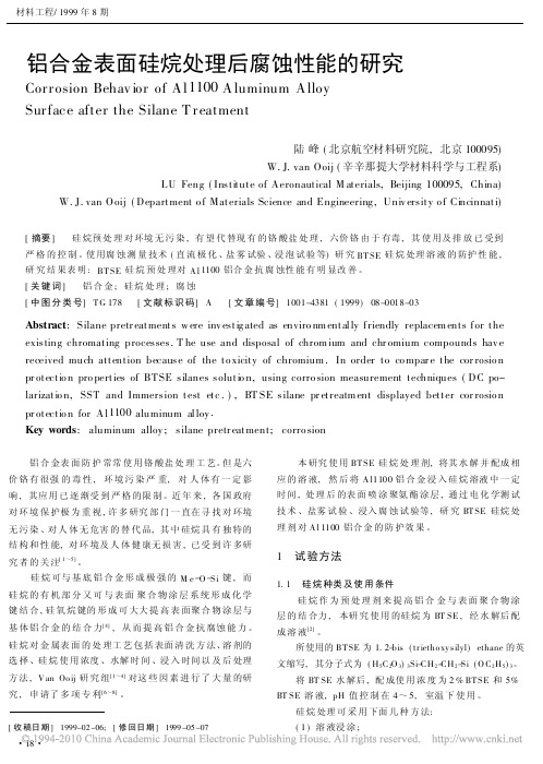
铝合金表面硅烷处理后腐蚀性能的研究Corrosion Behav ior of A l1100A luminum A lloySurface after the Silane T reatment陆峰(北京航空材料研究院,北京100095)W.J.van Ooij(辛辛那提大学材料科学与工程系)LU Feng(Institute of Aeronautical M aterials,Beijing100095,China) W.J.van Ooij(Department o f Materials Science and Engineering,Univ ersity o f Cincinnati)[摘要] 硅烷预处理对环境无污染,有望代替现有的铬酸盐处理,六价铬由于有毒,其使用及排放已受到严格的控制。
使用腐蚀测量技术(直流极化、盐雾试验、浸泡试验等)研究BT SE硅烷处理溶液的防护性能,研究结果表明:BT SE硅烷预处理对A l1100铝合金抗腐蚀性能有明显改善。
[关键词] 铝合金;硅烷处理;腐蚀[中图分类号]T G178 [文献标识码]A [文章编号]1001-4381(1999)08-0018-03Abstract:Silane pretr eatments w ere inv estig ated as enviro nm entally friendly replacem ents for the existing chromating processes.T he use and disposal of chrom ium and chr omium compounds hav e received much attention because of the to xicity of chromium.In order to co mpar e the cor rosio n pr otectio n pro perties of BTSE silanes solutio n,using corro sion measurement techniques(DC po-larizatio n,SST and Immersion test etc.),BT SE silane pr etreatm ent displayed better cor rosio n pr otectio n for Al1100aluminum alloy.Key words:aluminum alloy;silane pretr eatment;corro sion 铝合金表面防护常常使用铬酸盐处理工艺。
混凝土结构中钢筋在应力作用下的腐蚀特征
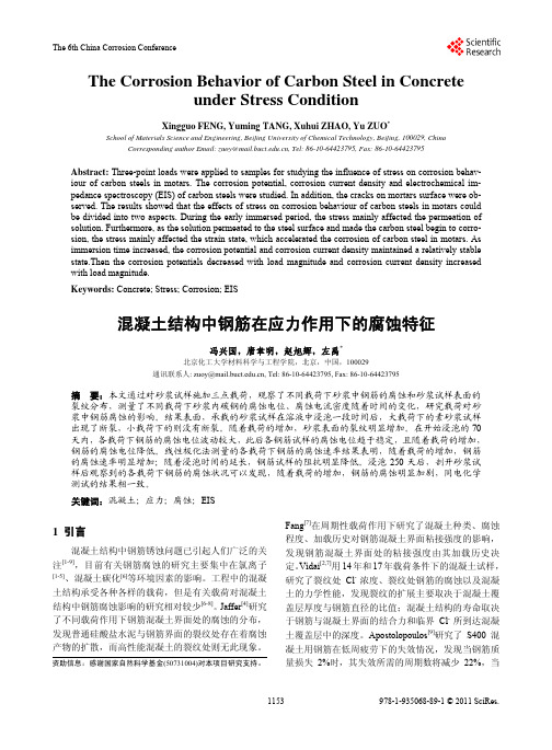
The Corrosion Behavior of Carbon Steel in Concreteunder Stress ConditionXingguo FENG, Yuming TANG, Xuhui ZHAO, Yu ZUO*School of Materials Science and Engineering, Beijing University of Chemical Technology, Beijing, 100029, China Corresponding author Email: zuoy@, Tel: 86-10-64423795, Fax: 86-10-64423795Abstract: Three-point loads were applied to samples for studying the influence of stress on corrosion behav-iour of carbon steels in motars. The corrosion potential, corrosion current density and electrochemical im-pedance spectroscopy (EIS) of carbon steels were studied. In addition, the cracks on mortars surface were ob-served. The results showed that the effects of stress on corrosion behaviour of carbon steels in motars could be divided into two aspects. During the early immersed period, the stress mainly affected the permeation of solution. Furthermore, as the solution permeated to the steel surface and made the carbon steel begin to corro-sion, the stress mainly affected the strain state, which accelerated the corrosion of carbon steel in motars. As immersion time increased, the corrosion potential and corrosion current density maintained a relatively stable state.Then the corrosion potentials decreased with load magnitude and corrosion current density increased with load magnitude.Keywords: Concrete; Stress; Corrosion; EIS混凝土结构中钢筋在应力作用下的腐蚀特征冯兴国,唐聿明,赵旭辉,左禹*北京化工大学材料科学与工程学院,北京,中国,100029通讯联系人: zuoy@, Tel: 86-10-64423795, Fax: 86-10-64423795摘要:本文通过对砂浆试样施加三点载荷,观察了不同载荷下砂浆中钢筋的腐蚀和砂浆试样表面的裂纹分布,测量了不同载荷下砂浆内碳钢的腐蚀电位、腐蚀电流密度随着时间的变化,研究载荷对砂浆中钢筋腐蚀的影响。