JYH21CT-EN
Extech CTH10A 用户手册说明书

USER MANUALRadio Controlled Clock with Temperature & HumidityModel CTH10AIntroductionThank you for selecting the Extech Model CTH10A Radio Controlled Clock with Hygro‐Thermometer displays. The CTH10A is a real‐time calendar Clock (12/24 hour) that also displays temperature and relative humidity measurements taken from its internal environmental sensors. The clock can be set manually or automatically using the RC‐WWVB time signal. The CTH10A includes an audible/visible daily alarm function with ‘snooze’ mode.This device is shipped fully tested and calibrated and, with proper use, will provide years of reliable service. Please visit our website () to check for the latest version of this User Guide, Product Updates, Product Registration, and Customer Support.Meter DescriptionA1: RC‐WWVB time signal IconA2: Time DisplayA3: DateA4: Day of WeekA5: Indoor HumidityA6: Indoor TemperatureB1: ‘Snooze’ ButtonB2: ‘MODE/SET’ ButtonB3: ‘+ 12/24’ ButtonB4: ‘‐ C/F ’ ButtonB5: ‘RESET’ ButtonB6: ‘AL ON/OFF’ ButtonC1: Wall Mount HoleC2: Battery compartmentC3: Tilt StandOperationGetting StartedOpen the rear battery compartment, insert three (3) ‘C’ type batteries observing correct polarity and then close and secure the compartment cover. Press the Reset button (using the tip of a paper clip or pin) in order to initialize the meter.Automatic Time Setting∙After inserting the batteries and resetting the unit as described above, the clock automatically scans for the WWVB time signal and the icon flashes on the LCD.flashesIndicating now is receiving WWVB signalturns onIndicating signal receivedsuccessfullydisappears,Indicating signalreception failed∙The clock automatically synchronizes with the WWVB radio signal every day at 2am to maintain accurate time. If synchronization with the signal fails, the signal icon disappears;the clock then attempts to synchronize with the WWVB signal at 3, 4, and 5am.∙The clock can be set to scan the time signal manually by holding the button (B4) for 3 seconds. Note: If a manual scan is attempted with the signal icon showing, the signal icon will disappear and the manual scan will have to be attempted again. Each reception takes about5 minutes. If reception fails, scanning stops and the signal icon disappears; the scan thenrepeats on the next full hour (e.g. if a scan failed at 8:20am a scan will be tried again at 9am). ∙Stop scanning by holding “” button (B4) for 3 seconds.Note: Buttons will not function while scanning for the WWVB time signal.Manual Time Setting∙In the time display mode, hold the “MODE” button (B2) for 3 seconds to enter the Clock/Calendar setting Mode.∙Press “+” (B3) or “‐” (B4) button to adjust the setting and press the “MODE” button (B2) to confirm each setting and move to the next setting.∙The setting sequence is as follows: Hour, Minute, Second, Year, Month/Day sequence, Month, Day, DST.Notes:1.All setting modes will automatically exit after 15 seconds of inactivity.2.Press and hold the plus or minus button for faster scrolling of digits while editing.3.For Time Zones: The default setting is zone “P”. Hold “+” (B2) button for 3 seconds to changeto another zone “P” “M” “C” or “E” Pacific, Mountain, Central, and Eastern.4.DST: When the DST function is activated (Daylight Saving Mode) “DST” will be shown on theLCD. Set ‘DST’ as described in the Manual Time Setting section above.Daily Alarm Setting∙Press “MODE” button (B2) to view the Alarm Time, “AL” is shown on the display.∙When viewing the Alarm Time, hold “MODE” button (B2) for 3 seconds to enter the Alarm Time setting mode. Press “+” (B3) or “‐” (B4) button to adjust the alarm time. Press the “MODE” button (B2) to confirm the setting and move to the next setting.∙Press “AL ON/OFF” Button (B6) to activate or deactivate the alarm. If the alarm is on, thealarm icon " " appears on the display.Snooze Alarm∙Press the “SNOOZE” (B1) button when the alarm tone sounds. The alarm snoozes for approx. 5 minutes, after which time it alerts again. “” flashes on the LCD during the snooze time. This process can be repeated 7 times.∙Except for the “SNOOZE” button, any button can be pressed to stop the snooze alarm.Otherwise, the alarm signal sounds for 2 minutes, then stops automatically.12/24 Hour Display ModePress the “12/24” (B3) button to select the 12 or 24 hour mode.Thermometer and Relative Humidity Displays∙The CTH10A includes internal temperature and relative humidity sensors. Temperature and relative humidity measurements are displayed on the lower right side of the clock. ∙Press the “°C/°F” (B4) button to select C: Celsius or F: Fahrenheit units.∙If the temperature exceeds the measurable range, LL.L (beyond the minimum temperature) or HH.H (beyond the maximum temperature) will be shown on the LCD. Important Notes∙The clock loses time information when the batteries are removed.∙Do not expose the Clock to direct sunlight, extreme temperatures, or high humidity∙Never clean the device using abrasive or corrosive materials or products. Use a damp cloth to wipe the housing clean as necessary.Battery ReplacementWhen the Clock no longer displays digits and text please replace the batteries. Open the rear battery compartment, insert three (3) ‘C’ type batteries observing correct polarity and then close and secure the compartment cover. Press the Reset button (using the tip of a paper clip or pin) in order to initialize the meter.Never dispose of used batteries or rechargeable batteries in household waste.As consumers, users are legally required to take used batteries to appropriate collection sites,the retail store where the batteries were purchased, or wherever batteries are sold. Disposal: Do not dispose of this instrument in household waste. The user is obligated to take end‐of‐life devices to a designated collection point for the disposal of electrical and electronic equipment. SpecificationsDisplay Extra‐large multi‐function LCDCalendar Clock Real‐time calendar clock (up to year 2069)Time signal detector RC‐WWVB radio signal automatically sets the time (clocktime may also be manually set)Temperature Measurement range 0~50o C (32~122o F)Storage Temperature ‐20~60o C (‐4~140o F)Temperature Resolution 0.1 o C or o FTemperature Accuracy ±1.5°C (±3°F): ‐5°C to 0°C (23°F to 32°F)±1°C (±2°F): 1°C to 30°C (33°F to 86°F)±3°F (±1.5°C): 31°C to 50°C (87°F to 122°F)Over‐range temp. indication HH.H displayUnder‐range temp. indication LL.L displayR.H. Measurement range 20~99% Relative HumidityR.H Accuracy 20% to 40% RH: ±8% RH (@25°C)41% to 70% RH: ±6% RH (@25°C)71% to 90% RH: ±8% RH (@25°C)Power supply Three (3) ‘C’ type batteriesDimensions 29 x 43 x 3.8 cm (11.4 x 17 x 1.5 in.)Weight 1.25 kg (2.75 lbs.)Copyright © 2015 FLIR Systems, Inc.All rights reserved including the right of reproduction in whole or in part in any formISO‐9001 Certified。
JYH21CT拉丝板

JYH21CT简介新一代无镍、无钼,高抗腐蚀的环保不锈钢。
除拥有与304基本相同的性能外,更具有比304优异的导热性能,同时,还减少了深加工后的迟效性破裂。
不受国际市场镍、钼价格大幅变动的影响,JYH21CT价格相对平稳,比304价格更具优势。
JYH21CT的特点;1.优异的抗腐蚀性1)铬含量提高至21%,具有和SUS304同样优异的抗腐蚀性能。
2)因为降低了碳、氮等不纯物质,同时添加了具有稳定作用的钛元素,因此焊接后也能保持良好的抗腐蚀性。
2.出色的成形性机械特性和SUS436L相同,较SUS430优异。
3.价格优势及其稳定性1)因为不需添加镍,所以价格比SUS304便宜。
2)因为不需添加镍、钼,即使这两种金属涨价也不会受影响。
4.导热性能优异,节能因为JYH21CT的热导率比SUS304高约30%,所以在烹饪产品的应用上,更节约时间和能源,加上其良好的导磁性能,在电磁炉上使用更能显出材料的优势,节能效果良好。
5.抗内应力破裂性由于铁素体的固有特性,深加工后的部件不会因内应力的释出产生迟延破裂,因此一般不需要作退火处理,从而降低了加工成本。
JYH21CT不锈钢性能1、优异的抗腐蚀性。
铬含量提高至21%,具有和SUS304同样优异的抗腐蚀性。
因为降低了碳、氮等不纯物质,并添加了具有稳定作用的钛元素,焊接后也能保持良好的抗腐蚀性。
2、出色的成形性机械特性较SUS430优越。
3、价格优势及其稳定性因为不需要添加镍,所以价格比SUS304更具竞争力。
因为不需添加镍、钼,即使这两种金属涨价也不会受影响。
4、与SUS304相比密度低,重量相同的情况下,材料面积约可扩2.5%。
导热性能好。
热膨胀少。
本公司出售SUS XM7不锈钢板材,SUS XM7不锈钢棒材,SUS XM7不锈钢带材,SUS XM7不锈钢线材,SUSXM7不锈钢弹簧线,SUS XM7不锈钢中硬线,SUS XM7不锈钢全软线,SUS XM7不锈钢螺丝线,SUS XM7不锈钢扁钢,SUS XM7不锈钢槽钢,SUS XM7不锈钢角钢,SUS XM7不锈钢矩形管,SUS XM7不锈钢方管,SUS XM7不锈钢六角棒,SUS XM7不锈钢钢丝绳,SUS XM7不锈钢方钢,SUS XM7不锈钢卷板,SUS XM7不锈钢卷带,SUS XM7精密钢带,SUS XM7不锈钢无缝管,SUS XM7不锈钢管,易车棒,SUS XM7不锈钢圆棒,SUS XM7不锈钢光亮棒,SUS XM7不锈钢研磨棒,SUS XM7不锈钢大口径无缝管,SUS XM7不锈钢毛细管,SUS XM7不锈钢弹簧片,SUS XM7不锈钢黑棒,SUS XM7不锈钢焊接管,SUS XM7不锈钢拉伸带,SUS XM7不锈钢冲压带●XM7化学成份:碳C :≤0.08锰Mn:≤2.00硅Si:≤1.00磷P :≤0.045硫S :≤ 0.030镍Ni:8.50~10.50铬Cr:17.00~19.00铜Cu:3.00~4.00(奥氏体型)。
CommScope 产品说明书

660000222 Rev C Page © 2019 CommScope.All Rights er Manual INTRODUCTION . . . . . . . . . . . . . . . . . . . . . . . . . . . . . . . . . . . . . . . . . . . . . . . . . . . . . . . . . . . . . . . . . . . . . . . . . . . . . .2Revision History . . . . . . . . . . . . . . . . . . . . . . . . . . . . . . . . . . . . . . . . . . . . . . . . . . . . . . . . . . . . . . . . . . . . . . . .2Trademark Information. . . . . . . . . . . . . . . . . . . . . . . . . . . . . . . . . . . . . . . . . . . . . . . . . . . . . . . . . . . . . . . . . . . .2Applicable Standards . . . . . . . . . . . . . . . . . . . . . . . . . . . . . . . . . . . . . . . . . . . . . . . . . . . . . . . . . . . . . . . . . . . . .2Admonishments. . . . . . . . . . . . . . . . . . . . . . . . . . . . . . . . . . . . . . . . . . . . . . . . . . . . . . . . . . . . . . . . . . . . . . . . .3General Safety Precautions . . . . . . . . . . . . . . . . . . . . . . . . . . . . . . . . . . . . . . . . . . . . . . . . . . . . . . . . . . . . . . . . .31PRODUCT DESCRIPTION. . . . . . . . . . . . . . . . . . . . . . . . . . . . . . . . . . . . . . . . . . . . . . . . . . . . . . . . . . . . . . . . . . .31.1General Description . . . . . . . . . . . . . . . . . . . . . . . . . . . . . . . . . . . . . . . . . . . . . . . . . . . . . . . . . . . . . . . .31.2Major Components . . . . . . . . . . . . . . . . . . . . . . . . . . . . . . . . . . . . . . . . . . . . . . . . . . . . . . . . . . . . . . . . .31.3Transportation and Storage . . . . . . . . . . . . . . . . . . . . . . . . . . . . . . . . . . . . . . . . . . . . . . . . . . . . . . . . . . .51.4Specifications . . . . . . . . . . . . . . . . . . . . . . . . . . . . . . . . . . . . . . . . . . . . . . . . . . . . . . . . . . . . . . . . . . . .62UNPACKING AND INSPECTION. . . . . . . . . . . . . . . . . . . . . . . . . . . . . . . . . . . . . . . . . . . . . . . . . . . . . . . . . . . . . . .63UNPACKING A PANEL WITH A PRETERMINATED CABLE. . . . . . . . . . . . . . . . . . . . . . . . . . . . . . . . . . . . . . . . . . . . . .6(continued)Content Page26379-ATECP-91-005Rev F, January 2019EHDEnhanced High Density (EHD) PanelWith Preterminated CableTECP-91-005 • Rev F • January 20194PANEL INSTALLATION. . . . . . . . . . . . . . . . . . . . . . . . . . . . . . . . . . . . . . . . . . . . . . . . . . . . . . . . . . . . . . . . . . . 134.1Overview . . . . . . . . . . . . . . . . . . . . . . . . . . . . . . . . . . . . . . . . . . . . . . . . . . . . . . . . . . . . . . . . . . . . . . 134.2Tools and Hardware Needed. . . . . . . . . . . . . . . . . . . . . . . . . . . . . . . . . . . . . . . . . . . . . . . . . . . . . . . . . 134.3Mounting an Unloaded Panel . . . . . . . . . . . . . . . . . . . . . . . . . . . . . . . . . . . . . . . . . . . . . . . . . . . . . . . . 134.4Grounding the Panel . . . . . . . . . . . . . . . . . . . . . . . . . . . . . . . . . . . . . . . . . . . . . . . . . . . . . . . . . . . . . . 165GENERAL CABLE REQUIREMENTS. . . . . . . . . . . . . . . . . . . . . . . . . . . . . . . . . . . . . . . . . . . . . . . . . . . . . . . . . . . 176OPERATION . . . . . . . . . . . . . . . . . . . . . . . . . . . . . . . . . . . . . . . . . . . . . . . . . . . . . . . . . . . . . . . . . . . . . . . . . . 186.1Sliding Out Blade to First Position. . . . . . . . . . . . . . . . . . . . . . . . . . . . . . . . . . . . . . . . . . . . . . . . . . . . . 186.2Accessing Connectors on Back of Adapter Pack . . . . . . . . . . . . . . . . . . . . . . . . . . . . . . . . . . . . . . . . . . . . 196.3Closing Blade. . . . . . . . . . . . . . . . . . . . . . . . . . . . . . . . . . . . . . . . . . . . . . . . . . . . . . . . . . . . . . . . . . . 196.4Removing Blade from Front . . . . . . . . . . . . . . . . . . . . . . . . . . . . . . . . . . . . . . . . . . . . . . . . . . . . . . . . . 206.5Removing Fiber Cover . . . . . . . . . . . . . . . . . . . . . . . . . . . . . . . . . . . . . . . . . . . . . . . . . . . . . . . . . . . . . 216.6Re-Installing Fiber Cover . . . . . . . . . . . . . . . . . . . . . . . . . . . . . . . . . . . . . . . . . . . . . . . . . . . . . . . . . . . 217TECHNICAL ASSISTANCE. . . . . . . . . . . . . . . . . . . . . . . . . . . . . . . . . . . . . . . . . . . . . . . . . . . . . . . . . . . . . . . . . 22INTRODUCTIONThis user manual describes the Enhanced High Density (EHD) Panel, Included in thisuser manual are all procedures required in installing the EHD Panel as well asoperation procedures.Revision HistoryISSUE DATE REASON FOR CHANGE19/2015Original.210/2015Added minimum cable bend radius and maximum patch cord size.33/2016Added applicable standards and panel grounding instructions.4July 2016Updated for front-access only designE October 2017Updated for product name change to SYSTIMAX.F January 2019Removed SYSTIMAX name; added transportation and storage guidelines. Trademark InformationCommScope (logo), CommScope, and Enhanced High Density Panel are trademarks. Applicable StandardsUL 60950-1, 2nd Edition, 2007-03-27 (Information Technology Equipment - Safety -Part 1: General RequirementsCSA C22.2 No. 60950-1-07, 2nd Edition, 2007-03 (Information Technology Equipment-Safety - Part 1: General Requirements)Page 2© 2019 CommScope. All Rights Reserved.TECP-91-005 • Rev F • January 2019Page 3© 2019 CommScope . All Rights Reserved.AdmonishmentsImportant safety admonishments are used throughout this manual to warn of possible hazards to persons or equipment. The admonishments — in the form of Dangers, Warnings, and Cautions — must be followed at all times.General Safety Precautions1PRODUCT DESCRIPTION 1.1General DescriptionThe Enhanced High Density (EHD) Panel is a pre-terminated fiber optic connector panel intended for use in large data centers in a direct connect or interconnect environment. The EHD Panel mounts in a 19-inch (48.26 cm) equipment rack with a 3-inch or 5-inch channel. In each 1RU of rack space, a fully loaded panel provides 144 LC terminations using duplex LC adapters.The EHD Panel is designed for ease of installation and access. It is available witheither left- or right-side cable entry. The panel features sliding blades (three per 1RU ofrack space), providing full access to adapters and connectors. Each blade can accommodate four adapter packs. The EHD Panel is available with either a black or sky white baked enamel exterior.1.2Major ComponentsFigure 1shows the main components of the EHD Panel. They are as follows:Danger is used to indicate the presence of a hazard that will cause severe personalWarning is used to indicate the presence of a hazard that can cause severeCaution is used to indicate the presence of a hazard that will or can causeWhen mounting equipment in the rack make sure mechanical loading is evenThe rack should safely support the combined weight of all equipment it supports.This equipment is to be installed only in Restricted Access Areas (dedicatedand 110-18 of the National Electrical Code, ANSI/NFPA 70.In this figure, the 2RU panel is shown. Main components are analogous forTECP-91-005 • Rev F • January 2019•Blade—holds adapter packs or cabled modules; slides out to two front access positions and is removable from front. There are three blades per RU rack space.REFERENCE)Figure 1. EHD Panel Main Components (2RU Model Shown)•Fiber Cover—holds down fibers on each blade to prevent them from being inadvertently snagged or misrouted.•Grounding Location—is where a two-hole lug and ground wire are attached to connect panel ground PEM nuts to office ground. A two-hole lug is provided withthe product; the ground wire is not.•Mounting Brackets—can be flipped around to provide either front- or rear-facing mounting on a channel rack.•Front Door—swings down to provide access to the interior of the panel. The door features a double hinged design that allows users to open the door withoutinterfering with equipment below the panel on the same rack, or also to allow thedoor to lay flat for easy access to the bottom blade.•Designation Label—provides physical space for recording fiber designations.•Duplex LC Adapter Pack—(shown for reference) mounts within the blade.Product offerings for adapter packs include LC adapter packs in singlemode APCor UPC style.Page 4© 2019 CommScope. All Rights Reserved.TECP-91-005 • Rev F • January 2019Page 5© 2019 CommScope . All Rights Reserved.1.3Transportation and StorageProducts packaged in cartons may be stacked two high in transportation and storage. Some products packaged in spools may be stacked two high in transportation and storage as shown in Figure 2. See product packaging labels for designation.Figure 2. Stacked SpoolsTECP-91-005 • Rev F • January 2019Page 6© 2019 CommScope . All Rights Reserved.1.4SpecificationsTable 1 lists specifications for the EHD Panel. Table 2 summarizes the supported adapter packs and modules for the EHD Panel.2UNPACKING AND INSPECTION1.Inspect the exterior of the shipping container(s) for evidence of rough handlingthat may have damaged the components in the container.2.Unpack each container while carefully checking the contents for damage andverify with the packing slip.3.If damage is found or parts are missing, file a claim with the commercial carrierand notify CommScope Customer Service. Save the damaged cartons for inspection by the carrier.4.Refer to Topic 7 on Page 22 if you need to contact CommScope.5.Save shipping containers for use if equipment requires shipment at a future date.3UNPACKING A PANEL WITH A PRETERMINATED CABLEThe pre-terminated panel is shipped with the panel mounted on top of a spool containing the cable. The stub end of the cable is unwound to a splice vault or other point of termination. To protect the panel and cable windings contained within the upper cylinder of the shipping unit, It is critical to leave the foam packaging material surrounding the panel in place until the unit has been transported to the final installation location. Transporting the unit without the foam packaging in place may result in damage to the panel and/or cable. To unpack and mount a fully loaded panel, use the following procedure.Table 1. EHD Panel Specifications PARAMETER SPECIFICATION REMARKSOperating conditions−14°F to +140°F (−10°C to +60C) Humidity10% to 95% RH No condensation Storage conditions−40°F to +158°F (−40°C to +70°C) Dimensions (2RU) D x W x H(with mounting brackets)19.64 in. (49.9 cm) D x 19.09 in. (48.5 cm) W x 3.5 in. (6.04 cm) H Width without mounting brack-ets: 17.27 in. (43.9 cm)Weight per 2RU 23.4 lbs. (1.06 Kg)Table 2. EHD Panel Supported Adapter Packs and ModulesDESCRIPTIONFRONT CONNECTOR TYPE FRONT PORT COUNT REAR CONNECTOR TYPE REAR PORT COUNT FIBER CONFIGURATION LC Adapter Pack LC 24LC 24NATECP-91-005 • Rev F • January 2019Page 7© 2019 CommScope . All Rights Reserved.1.Cut off the external plastic as shown in Figure 3.Figure 3. Cutting Off External Plastic2.Cut off the cardboard wrap on the cable spool as shown in.Figure 4.Figure 4. Cutting Off Cardboard Wrap on Cable SpoolUse caution when unpacking and installing the EHD Panel. Avoid twistingUse caution when removing packaging materials. Sharp utensils canTECP-91-005 • Rev F • January 20193.Remove the four carousel locking screws shown in Figure 5 to unlock thecarousel, allowing the spool to rotate freely,CABLE STUBSCREWS (4X)25873-AFigure 5. Carousel Locking Screws and Cable Stub4.Pay out the cable stub as indicated by the red arrow in Figure 5, pulling cable endto termination location.5.Remove the four wing nuts shown in Figure6.REMOVE WINGNUTS (4X)25874-AFigure 6. Removing Wing NutsPage 8© 2019 CommScope. All Rights Reserved.TECP-91-005 • Rev F • January 2019Page 9© 2019 CommScope . All Rights Reserved.6.Lift off the top cover to expose the panel packaging as shown in Figure7.Figure 7. Lifting Off Top CoverTECP-91-005 • Rev F • January 2019Page 10© 2019 CommScope . All Rights Reserved. 7.Remove the outer rim as shown in Figure 8.Figure 8. Lifting Off Outer Rim8.Remove and unpack the accessories contained in shipment carton shown on topof the packaging foam in Figure 9.Page 11© 2019 CommScope . All Rights Reserved.Figure 9. Shipment Carton Containing Accessories9.Remove and unpack the plastic wrapper containing the EHD Panel, as shown inFigure 10.Figure 10. EHD Panel in Plastic WrapperPage 12© 2019 CommScope . All Rights Reserved.10.Lift panel off of spool and carefully uncoil remaining cable. Use caution to avoidtwisting the cable. Refer to Figure 11.Figure 11. Lifting Off EHD Panel11.Follow the procedure given in Topic 4 to install the panel on the frame.12.Splice cable stub end per local practice, using blocking kit if required.Page 13© 2019 CommScope . All Rights Reserved.4PANEL INSTALLATION4.1OverviewThe EHD Panel is shipped on a spool, preterminated with 144 LC connectors per rack unit (RU). It is available in both left- and right-cable-entry versions. A blocking kit is provided for the purpose of splicing the provided cable into a splice bay such as the OMX.After mounting, the panel must be grounded. Use a #2 Phillips Screwdriver to tighten the M4 screws through the ground lug (provided) into the panel ground PEM nuts, as described in Topic 4.4 on Page 16. Ground cables are NOT provided with the panel.4.2Tools and Hardware NeededUse a #2 Phillips Screwdriver and the supplied #12-24 screws to secure the panel to the equipment rack.4.3Mounting an Unloaded PanelThe panel is to be installed in a 19-inch (482.6mm) equipment rack with a 3-inch or 5-inch channel. Use the following procedure to mount the 1RU/2RU panel.1.Obtain the following tools and equipment:•Phillips #2 screwdriver;•Mounting hardware provided.2.Determine whether the panel will be installed on front or rear and whether on a 3-inch or 5-inch channel. Install the mounting brackets provided in the locations shown in the following figures (which are representative of other RU sizes, also):•Figure 12 for 2RU mounting on a 5-inch channel; •Figure 13 for 2RU mounting on a 3-inch channel;•Figure 14 for 1RU mounting on a 5-inch channel; or •Figure 15for 1RU mounting on 3-inch channel.This equipment is to be installed only in Restricted Access Areas (dedicatedand 110-18 of the National Electrical Code, ANSI/NFPA 70.The panel is shipped with the mounting brackets already installed in the the rear position.Figure 12. 2RU Mounting Bracket Positions (Front and Rear on 5-Inch Channel)Figure 13. 2RU Mounting Bracket Positions (Front and Rear on 3-Inch Channel) Page 14© 2019 CommScope. All Rights Reserved.Figure 14. 1RU Mounting Bracket Positions (Front and Rear on 5-Inch Channel)Figure 15. 1RU Mounting Bracket Positions (Front and Rear on 3-Inch Channel)3.Hold the panel up to the assigned mounting space and align the holes in themounting brackets with the holes in the equipment rack as shown in Figure 16.Secure the panel to equipment rack using the #12-24 screws provided. Torque these screws to approximately 27 pound-inches (3.1 Newton meters).Page 15© 2019 CommScope. All Rights Reserved.Figure 16. Mounting the Panel on the Equipment Rack (2RU Model Shown)4.4Grounding the PanelA termination (for an M4 screw) is provided on the panel for a frame groundconnection. The connection must be made in accordance with local and nationalelectrical codes. Use the following procedure, referring to Figure 17.1.Locate the ground location on the panel. At the grounding location, remove theprotective tape from the panel.Page 16© 2019 CommScope. All Rights Reserved.Page 17© 2019 CommScope . All Rights Reserved.Figure 17. Grounding the Paneling AWG 14 (1.6mm) solid copper wire, secure a crimp lug to one end of theground wire (installer provided). Secure the crimp lug to panel with two M4 screws. Torque the screws to approximately 15 pound-inches (1.7 Newton meters).3.Connect the other end of the ground wire to the earth ground conductor. Ensurethis connection is made using methods and hardware that meets all applicable local and national electrical codes.5GENERAL CABLE REQUIREMENTSPre-terminated EHD Panels use RBR G657.A1 reduced-bend-radius singlemode fiber. Installers need to follow the manufacturer recommended settings when testingand splicing the RBR G657.A1 fiber to the G.652 standard singlemode fiber. Pleasealert contractors to this fact.The minimum cable bend radius is 10 inches (25.4 cm).CommScope recommends the following type patch cords for use in the EHD Panel: •2-Fiber UPC LC Singlemode Dual-Zip 1.7mm patch cord FPCT-SPLC-S-xMReliable earthing of rack-mounted equipment should be maintained. connections to the branch circuit.26275-A1RU CHASSISSECURE TO OFFICE GROUND•2-Fiber UPC LC Singlemode Dual-Zip 1.7mm RBR patch cord FPCTE-SPLC-S-xM•2-Fiber UPC LC Singlemode Dual-Zip 2mm patch cord FPC2-SPLC-S-xM•2-Fiber UPC LC Singlemode Dual-Zip LSZH 2mm patch cord FPCH2-SPLC-S-xM•2-Fiber UPC Duplex LC Singlemode Dual-Zip 1.7mm patch cord FPCT-SDLC-S-xM•2-Fiber UPC Duplex LC Singlemode Dual-Zip 1.7mm RBR patch cord FPCTE-SDLC-S-xM•2-Fiber UPC Duplex LC Singlemode Dual-Zip 2mm patch cord FPC2-SDLC-S-xM•1-Fiber UPC LC Singlemode 1.7mm patch cord FPCF-SPLC-S-xM•1-Fiber UPC LC Singlemode 2mm patch cord FPCM-SPLC-S-xMThe maximum patch cord size that can fit in the panel is 2mm simplex or duplex.6OPERATION6.1Sliding Out Blade to First PositionTo slide out a blade to the first (access) position, pull out the pull arm on the right sideof the panel until the blade contacts the first detent, as shown in Figure 18.Figure 18. Sliding Out Blade to First (Access) PositionPage 18Page 19© 2019 CommScope . All Rights Reserved.6.2Accessing Connectors on Back of Adapter PackTo access the connectors on the back of an adapter pack, use the following procedure (refer to Figure 19):1.Place index finger into the concave loop on the slide mechanism, place thumb onthe pull arm, and squeeze index finger and thumb together.2.Slide out the blade until it stops in the second position, which permits theconnectors on the back of an adapter pack to be accessed.Figure 19. Sliding Out Blades to Second Position6.3Closing BladeTo close a blade, push in the push handle on the right side of the panel until the bladeis fully within the panel.This is the opposite action to what is shown in Figure 18 on Page 18.Page 20© 2019 CommScope . All Rights Reserved.6.4Removing Blade from FrontTo remove a blade from the front of the panel (Figure 20):1.Deflect the tab outward on the right side of the panel.2.Pull on a gray fiber management finger (not the white pull handle). The graymanagement finger is highlighted in yellow in the figure.Figure 20. Removing Blade From FrontPulling too far will damage the ribbons entering the back of the blade on aFIBERTECP-91-005 • Rev F • January 20196.5Removing Fiber CoverTo remove the fiber covers, remove the blades as described in Topic 6.4 on Page 20until the center is fully exposed, then:1.Squeeze the fingers at the center of the covers per the arrows shown in Figure 21.2.Pull upward on the cover and lift it off the blade.Figure 21. Removing Fiber Covers6.6Re-Installing Fiber CoverTo reinstall the fiber cover:1.Align the fiber cover with its home location and tilt the cover at about a 45 degreeangle and position the tip of the cover within the guides indicated in Figure 22detail 1.Page 21© 2019 CommScope. All Rights Reserved.TECP-91-005 • Rev F • January 2019Page 222.Swing down the cover until it presses into and locks within the cover holderindicated in Figure 22 detail 2.Figure 22. Re-Installing Fiber Cover7TECHNICAL ASSISTANCETo find out more about CommScope® products, visit us on the web atFor technical assistance, customer service, or to report any missing/damaged parts,visit us at /SupportCenter。
航空电连接器

文案编辑词条B 添加义项?文案,原指放书的桌子,后来指在桌子上写字的人。
现在指的是公司或企业中从事文字工作的职位,就是以文字来表现已经制定的创意策略。
文案它不同于设计师用画面或其他手段的表现手法,它是一个与广告创意先后相继的表现的过程、发展的过程、深化的过程,多存在于广告公司,企业宣传,新闻策划等。
基本信息中文名称文案外文名称Copy目录1发展历程2主要工作3分类构成4基本要求5工作范围6文案写法7实际应用折叠编辑本段发展历程汉字"文案"(wén àn)是指古代官衙中掌管档案、负责起草文书的幕友,亦指官署中的公文、书信等;在现代,文案的称呼主要用在商业领域,其意义与中国古代所说的文案是有区别的。
在中国古代,文案亦作" 文按"。
公文案卷。
《北堂书钞》卷六八引《汉杂事》:"先是公府掾多不视事,但以文案为务。
"《晋书·桓温传》:"机务不可停废,常行文按宜为限日。
" 唐戴叔伦《答崔载华》诗:"文案日成堆,愁眉拽不开。
"《资治通鉴·晋孝武帝太元十四年》:"诸曹皆得良吏以掌文按。
"《花月痕》第五一回:" 荷生觉得自己是替他掌文案。
"旧时衙门里草拟文牍、掌管档案的幕僚,其地位比一般属吏高。
《老残游记》第四回:"像你老这样抚台央出文案老爷来请进去谈谈,这面子有多大!"夏衍《秋瑾传》序幕:"将这阮财富带回衙门去,要文案给他补一份状子。
"文案音译文案英文:copywriter、copy、copywriting文案拼音:wén àn现代文案的概念:文案来源于广告行业,是"广告文案"的简称,由copy writer翻译而来。
多指以语辞进行广告信息内容表现的形式,有广义和狭义之分,广义的广告文案包括标题、正文、口号的撰写和对广告形象的选择搭配;狭义的广告文案包括标题、正文、口号的撰写。
Tron 产品说明书

COMPASS01-0226-03GYROTRAC SYSTEM FOC-WO 1.00SET21F COMPASS01-0226-03GYROTRAC SYSTEM FOC-WO 1.00SET PHLIA WIND DATA SYSTEM05106RM YOUNG WIND MONITOR - MA P221-1334 1.00SET XXX WIND DATA SYSTEM05108RM YOUNG WIND MONITOR HD P222-14537.00SET19F WIND DATA SYSTEM06206-27RM YOUNG MARINE WIND TRACKER -110/220VAC P222-1453 3.00SET19F WIND DATA SYSTEM06206-27RM YOUNG MARINE WIND TRACKER -110/220VAC SHAC31 P221-0710 1.00SET SHAC 101700TRON TR30 AIR EMERGENCY VHF AM RADIO P222-0087 1.00SET19F103170EPRIB - TRON 60AIS WITH FLOAT FREE BRACKET P223-0001 4.00SET19F103170EPRIB - TRON 60AIS WITH FLOAT FREE BRACKET P222-0670 1.00SET SHAT1305118DM100 VDR G2P221-1683*3 1.00SET BOND710S-00607SAFESEA S100 SART WITH MOUNTING POLE P222-00748.00SET PHLIA EPIRB8305083050 TRON 40S MKII (WITHOUT BRACKET)FOC-P218-2570 1.00SET19F EPIRB83310TRON 60S EPIRB W/FF BRACKET P222-0776 1.00SET19F EPIRB83310TRON 60S EPIRB W/FF BRACKET P222-0331 1.00SET GZLF EPIRB83310TRON 60S EPIRB W/FF BRACKET P222-0776 2.00SET SHAT EPIRB83310TRON 60S EPIRB W/FF BRACKET P222-0776 1.00SET XXX19 83330TRON 60GPS EPIRB WITH FLOAT FREE BRACKET P222-07767.00SET19F83330TRON 60GPS EPIRB WITH FLOAT FREE BRACKET P222-0776 1.00SET SHAT VHF / UHF87950P221-0958 1.00SET19F VHF / UHF87950P222-067039.00SET19F VHF / UHF87950SHAC26 P221-0014 1.00SET SHAC VHF / UHF87950P221-0631 1.00SET SHAT A45P & E ANEMOMETER P221-1367 1.00SET PANYUAC3161200407222A-00500 SAILOR 7222 VHF DSC Class A P222-0139 3.00SET19FAC3496400C1-70-A00S INTELLIAN C700 CERTUS TERMINAL P221-1117 1.00SET PHLIA AUTOPILOT ALPHAPILOT-IU*AUTOPILOT (CONTACT O/P) CONNECTION TERMINAL (LOCAL MADE)FOC 4.00SET19F GYROCOMPASS CMZ-900B2GYRO COMPASS P222-1289 1.00SET19F ECHO SOUNDER CVS-126KODEN ECHO SOUNDER (600W, 200KHZ, DC24V OPERATION)P221-0821 1.00SET PHLIA ECHO SOUNDER CVS-126KODEN ECHO SOUNDER (600W, 200KHZ, DC24V OPERATION)P222-0118 3.00SET PHLIA ECHO SOUNDER CVS-126KODEN ECHO SOUNDER (600W, 200KHZ, DC24V OPERATION)P222-090520.00SET PHLIA ECHO SOUNDER CVS-128KODEN ECHO SOUNDER(8.4-INCH COLOR LCD)P222-0905 2.00SET19F ECHO SOUNDER CVS-128KODEN ECHO SOUNDER(8.4-INCH COLOR LCD)P222-0905 1.00SET PHLIA ECHO SOUNDER CVS-FX2KODEN DIGITAL BROADBAND ECHO SOUNDER C/W TRANSDUCER & STANDARD ACCESSORIES FOC-WO-P215-1160 1.00SET PHLIA NAVTEX DPU-414-50B-E PRINTER P222-0996 1.00SET DL NAVTEX DPU-414-50B-E PRINTER SHAC21 P219-0539 1.00SET DL NAVTEX DPU-414-50B-E PRINTER SHAC21 P219-0538 1.00SET FZ NAVTEX DPU-414-50B-E PRINTER P219-0538 1.00SET PANYU NAVTEX DPU-414-50B-E PRINTER CONSIGNMENT 1.00SET PHLIA NAVTEX DPU-414-50B-E PRINTER P221-0068 2.00SET PHLIA NAVTEX DPU-414-50B-E PRINTER P222-1020 1.00SET SHAI DT885FF ENTEL FIRE FIGHTER RADIO (UHF), ATEX IIB P221-014712.00SET19FDT885FF ENTEL FIRE FIGHTER RADIO (UHF), ATEX IIB ENT-P221-0011 6.00SET SHACDT985FF ENTEL FIRE FIGHTER RADIO (UHF), ATEX IIC P221-14248.00SET19FDT985FF ENTEL FIRE FIGHTER RADIO (UHF), ATEX IIC P222-118720.00SET19F VHF / UHF DX482ENTEL UHF P218-1451 1.00SET19F VHF / UHF DX482ENTEL UHF P218-1451 2.00SET SHAT VHF / UHF DX482ENTEL UHF P218-1451*2 3.00SET SHAT DX585M-IS UL913 INTRINSICALLY SAFE UFH (NON EU)P222-11417.00SET19F FAX / WEATHER FAX FAX-236BROTHER FAX MACHINE ( AC 220V )FOC-WO-P211-0201 1.00SET21F FAX / WEATHER FAX FAX-236BROTHER FAX MACHINE ( AC 220V )FOC-WO-P211-0201 1.00SET PHLIA VHF / UHF FM8800S*VHF (SECOND HAND)FOC-WO-P215-0960 1.00SET SGP GC80SIMRAD GYRO COMPASS P221-1563 1.00SET PHLIA GPS / DGPS GP-170GPS P222-0649 1.00SET PHLIA PUBLIC ADDRESSER HPA-7300PUBLIC ADDRESSER/ TALK-BACK SYSTEM CONSIGNMENT-PGH270210.70SET PANYU PUBLIC ADDRESSER HPA-9200PUBLIC ADDRESSER/ TALK BACK SYSTEM CONSIGNMENT-PGH27021 1.00SET PANYU VHF / UHF HT544ENTEL HANDHELD VHF (I.S. TYPE) WITH LCD DISPLAY ENT-P220-0003 2.00SET SHAC VHF / UHF HT583(RED-BEZEL)ENTEL I.S. UHF P221-0147 4.00SET19F VHF / UHF HT583(RED-BEZEL)ENTEL I.S. UHF P221-106117.00SET19F VHF / UHF HT583(RED-BEZEL)ENTEL I.S. UHF P221-1061 3.00SET SHAT VHF / UHF HT649-GMDSS/P2ENTEL 2-WAY VHF P222-163411.00SET19F VHF / UHF HT649-GMDSS/P2ENTEL 2-WAY VHF P222-1634 6.00SET SHAT VHF / UHF HT782UHF P221-1424 1.00SET19F VHF / UHF HT782UHF ENT-P220-0003 2.00SET SHAC VHF / UHF HT883ENTEL I.S. UHF P218-12858.00SET19F VHF / UHF HT883ENTEL I.S. UHF ENT-P220-0003 1.00SET SHAC VHF / UHF HT883(RED-BEZEL)ENTEL I.S. UHF P218-1201 6.00SET13F VHF / UHF HT883(RED-BEZEL)ENTEL I.S. UHF P218-0235 4.00SET19F VHF / UHF HT883(RED-BEZEL)ENTEL I.S. UHF P218-0699 4.00SET19F VHF / UHF HT883(RED-BEZEL)ENTEL I.S. UHF ENT-P220-0003 6.00SET SHAC VHF / UHF HT883(RED-BEZEL)ENTEL I.S. UHF P218-0235 1.00SET SHATVHF / UHF HT982ENTEL I.S. UHF P220-0104 4.00SET19F TELEPHONE HX-26AUTO EXCHANGE TELEPHONE SYSTEM CONSIGNMENT-PGH27021 1.00SET PANYU TELEPHONE HX-72AUTO-TELEPHONE SYSTEM CONSIGNMENT-PGH27021 1.00SET PANYU ECDIS JAN-2000JRC ECDIS FOC-WO-P216-0876 1.00SET PHLIA NECST JAN-470-4ANN NECST CONSIGNMENT 1.00SET PHLIA JAN-5203-26D ROUTE PLANNING SYSTEM, 26", DESK TOP TYPE P220-1749 2.00SET19F ECDIS JAN-701B*ECDIS (SECOND HAND)FOC-WO-P213-1313*10.90SET SHAT FAX / WEATHER FAX JAX-90*WEATHER FAX (SECOND HAND)FOC-WO-P213-1313 1.00SET SGP VDR SVDR JCY-1850*JRC SIMPLIFIED VOYAGE DATA RECORDER (SECOND HAND)FOC-WO-P215-0960 2.00SET SGP ECHO SOUNDER JFC-7050-W/OTD FISH FINDER (WITHOUT TRANSDUCER)FOC-WO-P215-1346 1.00SET PHLIA ECHO SOUNDER JFE-400-25ECHO SOUNDER WITH 200KHZ + 50KHZ DUAL TRANSDUCER (BB TYPE)P222-0682 1.00SET19F ECHO SOUNDER JFE-570S*NAVIGATION ECHO SOUNDER (SECOND HAND)FOC-WO-P213-1313 1.00SET SGP ECHO SOUNDER JFE-680JRC ECHO SOUNDER (WITHOUT TRANSDUCER)P221-0849 1.00SET19F AIS JHS-183AUTOMATIC IDENTIFICATION SYSTEM (AIS)P221-0837 1.00SET19F VHF / UHF JHS-32A*JRC VHF (SECOND HAND)FOC-WO-P213-1313 1.00SET PHLIA VHF / UHF JHS-32A*JRC VHF (SECOND HAND)FOC-WO-P215-0960*10.90SET SGP VHF / UHF JHS-32A*JRC VHF (SECOND HAND)FOC-WO-P215-0960 1.00SET SGP VHF / UHF JHS-32B*VHF/FM RADIOTELEPHONE (SECOND HAND)CONSIGNMENT 1.00SET PHLIA VHF / UHF JHS-7 2 WAY VHF RADIOTELEPHONE P219-1575*1 1.00SET19F GPS / DGPS JLR-21GPS COMPASS P222-0030 1.00SET19F GPS / DGPS JLR-4340GPS RECEIVER GPS-124 (WITH 15M CABLE)P218-0312*2 1.00SET19F GPS / DGPS JLR-7700MKII*GPS NAVIGATOR (SECOND HAND)FOC-WO-P215-0960 1.00SET SGP RADAR JMA-3336RADAR - X-BAND 6KW, 3.9FT OPEN SCANNER 10.4" DISPLAY P222-0318 1.00SET PHLIA JMA-3404JRC MARINE RADAR X-BAND, 4KW DOME SCANNER, 12/24VDC FOC-WO-P220-0946 3.00SET PHLIAJMA-3406JRC MARINE RADAR X-BAND, 6KW OPEN SCANNER, 12/24VDC P220-0946 1.00SET PHLIA RADAR JMR-9225-6XC X-BAND COLOR RADAR, 6FT ANTENNA OUTPUT POWER: 25KW STAND-ALONE TYPE P222-0744 1.00SET21F RADAR JMR-9225-6XC X-BAND COLOR RADAR, 6FT ANTENNA OUTPUT POWER: 25KW STAND-ALONE TYPE P222-0744 1.00SET BOND RADAR JMR-9230-SC S-BAND COLOR RADAR, 12FT ANTENNA OUTPUT POWER: 30KW STAND-ALONE TYPE P222-06990.90SET21F RADAR JMR-9230-SC S-BAND COLOR RADAR, 12FT ANTENNA OUTPUT POWER: 30KW STAND-ALONE TYPE P222-0170 1.00SET BOND RADAR JMR-9230-SC S-BAND COLOR RADAR, 12FT ANTENNA OUTPUT POWER: 30KW STAND-ALONE TYPE P222-06990.10SET GD MF/HF RADIO JSB-196GM*150W MHF/HF SSB RADIOTELEPHONE (SECOND HAND)FOC-P215-0960*1 1.00SET SGP INMARSAT JUE-85*INMARSAT-C MARINE MOBILE EARTH STATION (SECOND HAND)FOC-WO-P215-09600.90SET SGP INMARSAT JUE-95SA INMARSAT MINI-C MARINE MOBILE EARTH STATION P222-0682 1.00SET19F AIS KAT-100KODEN AIS TRANSCEIVER (DC OPERATION)P218-19660.50SET PHLIA KAT-330KODEN AIS TRANSCEIVER P222-0118 1.00SET19FKAT-330KODEN AIS TRANSCEIVER P222-0118 2.00SET PHLIAKAT-330KODEN AIS TRANSCEIVER P222-0905 6.00SET PHLIA ECHO SOUNDER KDS-6000BB KODEN DIGITAL BROADBAND SEARCH LIGHT SONAR P222-1707 2.00PC1PHLIA GPS / DGPS KGP-915KODEN GPS GLONASS P222-0905 3.00SET19F GPS / DGPS KGP-915KODEN GPS GLONASS P221-0821 2.00SET PHLIA GPS / DGPS KGP-915KODEN GPS GLONASS P222-0905 2.00SET PHLIA GPS / DGPS KGP-922GPS NAVIGATOR P222-0118 1.00SET19F GPS / DGPS KGP-922GPS NAVIGATOR P222-0118 1.00SET PHLIA GPS / DGPS KTN-70A PLOTTER P216-1791 1.00PC1PHJUN GPS / DGPS KTN-70A PLOTTER P219-172215.00PC1PHLIA RADAR MDC-204010.4-INCH COLOR LCD MARINE RADAR FOC-WO-P220-0861 2.00PC1PHLIA RADAR MDC-7912P-6X-BAND RADAR P222-1023 2.00SET19F RADAR MDC-7912P-6X-BAND RADAR P222-1023 2.00SET PHLIA RADAR MDC-941A KODEN 8.4 INCH COLOUR RADAR WITH 25" RADOME P222-0905 3.00SET19F RADAR MDC-941A KODEN 8.4 INCH COLOUR RADAR WITH 25" RADOME P220-0294*10.90SET PHLIA RADAR MDC-941A KODEN 8.4 INCH COLOUR RADAR WITH 25" RADOME P219-0298 1.00SET PHLIA RADAR MDC-941A KODEN 8.4 INCH COLOUR RADAR WITH 25" RADOME P222-0118 1.00SET PHLIA RADAR MDC-941A KODEN 8.4 INCH COLOUR RADAR WITH 25" RADOME P222-170712.00SET PHLIA RADAR MDC-941A KODEN 8.4 INCH COLOUR RADAR WITH 25" RADOME P222-090514.00SET PHLIA COMPASS MS-100MAGNETIC COMPASS A/D CONVERTOR FOC-WO-P210-0101 1.00SET21F COMPASS MS-100MAGNETIC COMPASS A/D CONVERTOR FOC-WO-P210-0261 2.00SET21F VHF / UHF NCM-1770-E CONTROLLER SHAC14 P219-1237*1 2.00SET SHAC NAVTEX NCR-333NAVTEX RECEIVER P222-1108 2.00SET19F NAVTEX NCR-333NAVTEX RECEIVER P219-1511*20.20SET PHLIA NAVTEX NCR-333NAVTEX RECEIVER P220-1728*10.80SET PHLIA NAVTEX NCR-333*NAVTEX RECEIVER (SECOND HAND)FOC-WO-P215-0960 2.00SET SGP NEB-2000NSR EPRIB WITH AIS P222-129515.00SET PHLIANEB-2000C NSR EPRIB P222-0737*10.90SET PHLIANEB-2000C NSR EPRIB P222-0737 1.00SET PHLIA VHF / UHF NKG-52*PRINTER (SECOND HAND)FOC-P215-0960 1.00PC1SGP NKG900A NKG-900 PRINTER P222-0682 1.00PC19FNKG900A NKG-900 PRINTER P222-04918.00PC19FNKG900A NKG-900 PRINTER P222-0144 1.00PC SHAT ECHO SOUNDER NKG-901PRINTER (FLUSH MOUNT)P222-0597 2.00PC119F ECHO SOUNDER NKG-91PRINTER (FLUSH MOUNT) REFER TO NKG-901FOC 1.00PC119FRADAR NRT-1000RADAR SART P222-0737 3.00SET PHLIA AIS NTE-183-E AIS TRANSPONDER SHAC30 P220-0605*1 1.00SET DL VHF / UHF NTE-770S-E VHF TRANSCEIVER SHAC13 P219-1237*1 2.00SET SHAC NVR-3000VHF P222-1386 2.00SET19F VDR SVDR NW-6000NETWAVE VDR P219-2455*5 1.00SET19F AUTOPILOT PR-8000*TOKIMEC AUTOPILOT (SECOND HAND)FOC-WO-P213-1313 1.00SET SGP AUTOPILOT PT900AWOCMZ900S AUTOPILOT (WITHOUT CMZ-900S)P218-1659*1 1.00SET21F AIS R4*AIS (SECOND HAND)FOC-P215-0960 2.00PC1SGP AUTOPILOT RFU ANSCHUTZ (FEEDBACK UNIT) WITH LINKAGE FOR NP60FOC 1.00SET19F AUTOPILOT RFU ANSCHUTZ (FEEDBACK UNIT) WITH LINKAGE FOR NP60FOC-P218-1009 1.00SET19F VHF / UHF RT5022*SAILOR RT5022 VHF DSC (2nd HAND)CONSIGNMENT 1.00SET SGP GYROCOMPASS TG-5000*TOKIMEC GYROCOMPASS (SECOND HAND)FOC-P215-0960 1.00SET SGP GYROCOMPASS TG-5000*TOKIMEC GYROCOMPASS (SECOND HAND)FOC-WO-P213-1313 1.00SET SGP VHF / UHF TLKR8PACKAGE C/W RECHARGABLE BATTERY, BATTERY CHARGER, EARBUD & USER MANUAL FOC-WO-P213-0004 2.00SET21F TRANSPONDER TRONSART20JOTRON RADAR TRANSPONDER P222-0087 1.00SET19F TRANSPONDER TRONSART20JOTRON RADAR TRANSPONDER P222-195530.00SET19F TRANSPONDER TRONSART20JOTRON RADAR TRANSPONDER P222-0087 2.00SET DL TRANSPONDER TRONSART20JOTRON RADAR TRANSPONDER P222-0087 2.00SET PANYU。
Instruction 说明书

Follow instruction manualThe instruction manual is part of the product and an important element within the safety concept.• Read and follow instruction manual.• A lways keep instruction manual available for the product.• P ass on instruction manual to all subsequent users of the product.1. Intended useThe product is applicable for liquids with specific conductivity over 10 µS/cm. Theswitching unit can sense the resistance between probes. Conductivity measurement is suitable only for detecting the presence of liquid at a given level of the tank. This level is represented by the length of the probe. The conductive switch is suitable for fìlling or emptying control with 2 to 4 relay outputs working simultaneously or for level detection of 2-4 independent levels (in 1 or 2 tanks) with 2 independent relay outputs.2. Safety and responsibilityIn order to provide safety in the plant, the operator is responsible for the following measures:• P roducts may only be used for its intended purpose, see intended use • N ever use a damaged or defective product. Immediately sort out damaged product.• M ake sure that the piping system has been installed professionally and serviced regularly.• P roducts and equipment shall only be installed by persons who have the required training, knowledge or experience.• R egularly train personnel in all relevant questions regarding locally applicableregulations, safety at work, environmental protection especially for pressurised pipes.The personnel is responsible for the following measures:• K now, understand and follow the instruction manual and the advices therein.3. FunctionThe level switch consists of 1 or 2 switching unit and the KLN-2 type probes. Probes are to be connected to the 2281 type probe socket head that can be screwed into the tank. lf the material of the tank or its internal insulation is not conductive then a reference probe should be used in addition to the one, two, three or four probe(s), if the material of the tank is conductive, the tank can be used as a reference probe.4. Technical Data4.1 Technical Data of the switching unitProbe Voltage 5 V AC Probe current < 1 mA ACSensitivityAdjustable: 5 kΩ ... 100 kΩMax. cable capacity 4 nF Response max. 400 ms Setting accuracy (mech.)± 5 %Delay Adjustable: 0.5 ... 10 s Relay output 2x SPDTSwitching voltage 250 V AC1, 24 V DC Switching current 16A AC1Switching power 4000 vA AC1. 384 W DC Electrical strength 4 kVMechanical life-span 3 x10⁷ switches Electrical life-span 0,7x10⁵ switches Power supply Un 24 V AC/DCVoltage range allowed nominal voltage -15 %...+100 %Power consumption max. 2.5 VA/ W Ambient temperature -20°C ... +55°CElectrical connection max. 2.5 mm 2 / with insulation 1.5 mm 2Electrical protection Class III Ingress protection IP 20Mechanical connection DIN EN 60715 rail Mass240 g6. Installation• Mount s witching unit on DIN EN 60715 rail.• Cut the KLN-2 type probes to the length required for level detection on site. • Screw probes into the sockets.• Tighten the probe with an M6 nut.•Use separators at every 0.5 m for multiple probe devices to keep the probes apart.7. Electrical Connectionlf the wall of the tank is conductive no reference probe is needed, ln this case terminal C is to be connected to the tank. On multiple probe units E1 and E2 are marked with 1,,.4, the reference probe is marked with C. Admissible length of cable between signal processor and probes depends on cable capacity and conductivity. Make sure E1 in upper level, E2 buttom level.8. Putting into operation8.1 AdjustmentThe green LED (U n ) shows that the unit is on, the energized state of the relays areindicated by the E1 respectively E2 LEDs. Operating mode, delay ON and delay OFF can be set with the DIP switch on the front panel. tE1(s) and tE2(s) potentiometers are for adjusting the delay time. The sensitivity setting (R potentiometer) should comply with lhe conductivity of the fluid. Do not set sensitivity higher than required because the vapour precipilation may lead to operation disturbance.Selection of delay type for input E1ta: delay OFF Georg Fischer Piping Systems Ltd CH-8201 Schaffhausen Phone +41(0)52 631 30 26 / info.ps @georgfischer .com / GFDO 6354_4 (07.14)© Georg Fischer Rohrleitungssysteme AG CH-8201 Schaffhausen/Schweiz, 2014Printed in SwitzerlandInstruction manual2281 Conductive multipoint switch with dual channel relayGF Piping SystemsGeorg Fischer Piping Systems Ltd CH-8201 SchaffhausenPhone +41(0)52 631 30 26 / info.ps@ /GFDO 6354_4 (07.14)© Georg Fischer Rohrleitungssysteme AGCH-8201 Schaffhausen/Schweiz, 2014Printed in Switzerland8.2 Level detectionThe relay allows level detection of 2 independent levels even in one tank or in two separated tanks.8.3 State of relaysE1 E2 E1 E2 E1 E2 E1 E2Function 2xDelay type E1 taFunction 2xDelay type E1 taFunction 2xDelay type E1 taFunction 2xDelay type E1 ta1xONtbtb1xONtbtb1xONtbtb1xONtbtb8.4 Level controlSelection of contacts depends on required function.9. Maintenance, RepairThe device does not require regular maintenance. Repair within and beyond the wanantyperiod is carried out at the manufacturer‘s location.10. Storage• Ambient temperature: -30 to +70 °C• Relative humidity: max. 85%11. DisclaimerThe technical data are not binding. They neither constitute expressly warranted cha-racteristics nor guaranteed properties nor a guaranteed durability.They are subject to modification. Our General Terms of Sale apply.。
258 Encoders 金属杆壳型绝对类型 EC18A 水抗性强、重力扭矩强 18mm 尺寸 金属

259EncodersMetal ShaftInsulatedShaftThroughShaft TypeRing TypeStandard Codes 1. The ●marks shows the ON position.2. The ●marks : Connections between terminals and the 5 (COM) are ON.Waterproof PropertyImmersion of encoder, not in operation, in water at depth of 1m at normal temperature for 30 minutes.EC18AGAPosition No.123456789101112Rotation angle (° )3060901201501802102402703003301●●●●●●2●●●●3●●●●●●4●●●●5(COM )●●●●●●●●●●●●T E R M I N A L N O .EC18AGB20401Position No.12345678910111213141516Rotation angle (° )22.54567.590112.5135157.5180202.5225247.5270292.5315337.51●●●●●●●●2●●●●●●●●3●●●●●●●●4●●●●●●●●5(COM )●●●●●●●●●●●●●●●●T E R M I N A L N O .EC18AGB20407Position No.123456789101112131415Rotation angle (° )244872961201441681922162402642883123361●●●●●●●●2●●●●●●●●3●●●●●●●●4●●●●●●●●5(COM )●●●●●●●●●●●●●●●T E R M I N A L N O .EC18A /18mm Size Insulated Shaft Type(Two phase A and B )275EncodersMetal ShaftInsulated Shaft Through Shaft TypeRing Type1. When using an infrared reflow oven, solder may sometimes not be applied. Be sure to use a hot air reflow oven or a type that uses infrared rays in combination with hot air.2. The temperatures given above are the maximum temperatures at the terminals of the encoder when employing a hot air reflow method. The temperature of the PC board and the surface temperature of the encoder may vary greatly depending on the PC board material, its size and thickness. Ensure that the surface temperature of the encoder does not rise to 250℃ or greater.3. Conditions vary to some extent depending on the type of reflow bath used. Be sure to give due consideration to this prior to use.NotesEC05E EC21CEC28C, EC35CH250℃ min.230℃ to 245℃260℃230℃ min.220℃ 230℃180℃200℃180℃150℃150℃150℃60s to 120s 60s to 120s 2 min. min.ーー3s30s to 40s 25s to 60s40sー300s max.230s max.2 times max.1 time max.1 time max.Soldering surfacetemperatureSoldering temperatureHeating timeSoldering timeNo. of soldersEC09E, EC111, EC11E, EC11M, EC11N, EC18A,EC21A, EC28A, EC35A, EC35AH, EC50A Series100℃ max.260±5℃2 min. max.5±1s 2 times max.PreheatingDip solderingReference for Dip SolderingExample of Reflow Soldering ConditionReference for Manual SolderingEC10E, EC12D, EC12E EM11BEC40A100℃ max.100℃ max.110℃ max.260±5℃260℃ max.260℃ max.1 min. max.1 min. max.1 min. max.3±1s 3s max.10s max.2 times max.2 times max.1 timeTemperature profile300200100A BC Time (s)G max.F max.H max.E max.RoomtemperatureT e m p e r a t u r e (˚C )Pre-heating DEncoders / Soldering ConditionsEC05E, EC09E, EC10E, EC111, EC11E, EC11M, EC11N, EC12D, EC12E, EC18A, EC21A, EC28A, EC35A, EC35AH, EC40A, EC50A, EM11B, EC21C, EC28C, EC35CHSeries350℃ max.3s max. 1 timeTip temperatureSoldering timeNo. of soldersSeries ABCDEFGHNo. of reflows。
JYH21C新一代无镍,无钼,高铬高抗腐蚀性不锈钢简介
西德
DIN
- X8CrMnNi189(1.4371) X12CrNi177(1.4310)
(1.4324) X12CrNi188(1.4300) X12CrNiS188(1.4300) X12CrNiS188(1.4305) X5CrNi189(1.4301) X2CrNi189(1.4306)
- - X2CrNi1810(1.4311) X5CrNi1911(1.4303) X7CrNi12314(1.4833) X12CrNi2521(1.4845) X5CrNiMn1810(1.4401) X5CrNiMo1812(1.4436) X10CrNiMTi1810(1.4571) X2CrNiMo1812(1.4435) X2CrNiMo1810(1.4404) - X2CrNiMoN1812(1.4406) X2CrNiMoN1813(1.4429)
347 XM7 XM15 329 - -
S34700 S30430 S38100 S32900
- -
英国
BS
- 284 S 16 301 S 21
302 S 25 303 S 21 303 S 41 304 S 15 304 S 12
- - - 305 S 19 - 310 S 24 316 S 16
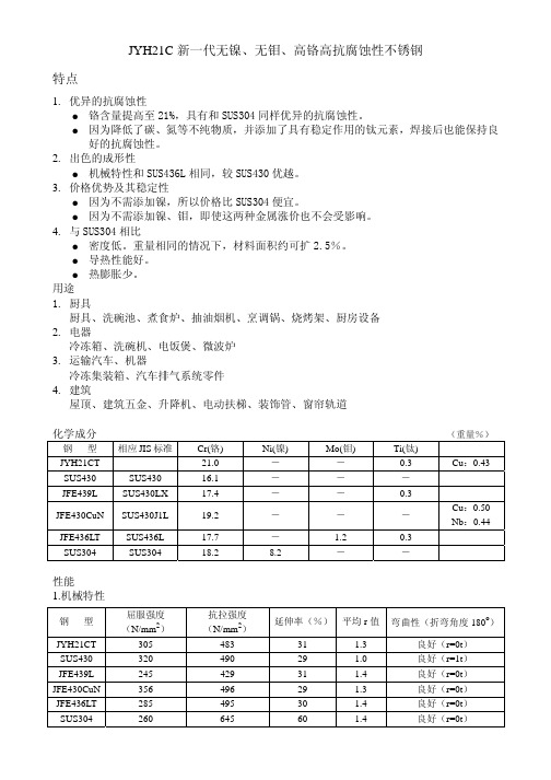
SUS436L SUS304
Cr(铬) 21.0 16.1 17.4
19.2
17.7 18.2
Ni(镍) - - -
-
- 8.2
Mo(钼) - - -
-
1.2 -
Ti(钛) 0.3 - 0.3
-
0.3 -
(重量%) Cu:0.43
Cu:0.50 Nb:0.44
性能 1.机械特性
安规陶瓷电容器(X1 Y2)中文
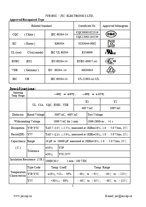
US-21903-A1-UL
Specifications:
Operating Temp. Range
-40℃ to +85℃ ,
UL, CSA, CQC, ENEC, VDE
-40℃ to +125℃
X1 400 VAC
Y2 300VAC
Dielectric Rated Voltage
300VAC, 400VAC
E-mail: jec@
JYH HSU(JEC) ELECTRONICS LTD
性能與試驗 ,依据IEC 60384-14:2005与 GB/T 14472制定
注意:1.依國際規範定義,耐壓測試時,零件承認或週期性試驗測試為一分鐘,經一分鐘測試之部品需報廢,
(此測試條件帶有破壞性測試),此耐壓測試應150V/s緩升或零啟動。時間從達到實驗電壓時計算. 2.批量生產時測試時間大於1秒鐘,直接施加額定試驗電壓. 重複耐電壓試驗可能損壞電容器.
0.55
JY562M2FY5V----
5600PF
10.2 7.5, 9.5or10.0 5
0.55
JY682M2FY5V----
6800PF
11.5 7.5, 9.5or10.0 5
0.55
JY822M2FY5V----
8200PF
13.0 7.5, 9.5or10.0 5
0.55
JY103M2FY5V----
承认规格详细参数 (Approved Spec. Data)
品名规格
D(MAX)
F±0.8
L
Y5V 222M/300VAC
6.8
7.5
25
T±0.5
3.5
d
0.55
洛菲电子清纱器说明书

精纺工程是要纺出相当均匀的细纱,然而却无法避免直 径不均匀细纱的出现。因此首先要区别细纱的不规则性 是正常或是真正的疵点。
细纱疵点也可以定义为细纱的不规则性。它可以造成后 道工程的困难或成品的瑕疵。在筒子工程中清纱器可以 检出并去除疵点,因此清纱器可说是络筒车的一部份。
切除疵点纱会妨碍筒子工程。筒子必须停车,切除疵点 纱,而且还必须打结。很明显的,以上动作将造成筒子 产量的损失。因此在品质与产量间需做个折衷,也就是 要寻求出最大疵点切除数及最低生产损失的交集点。这 折衷区分出以下不同:
Phone Fax E-Mail Internet
+41-43-488 11 11 +41-43-488 11 00 service@
YarnMaster 是 Loepfe Brothers Ltd. 洛菲公司在瑞士以及其 它各国所注册的商标 其它公司的产品名称,是属于该公司自己相关的商品名 称或注册商标。
10 模式 Mode
35
11 直径基准 Diameter Base (Group)
35
13 特别功能 Special Functions
36
14 系统架构内码 Configuration Codes
37
14 服务功能 1+2 Service Functions
37
15 测试模式 Test Mode
38
operationalnotes细纱清纱yarnclearing细纱疵点yarnfaults疵点等级分类classifcation10细纱清纱yarnclearing11细纱疵点分级yarnfaultclassifcation13常性发生疵纱imperections14细纱外观指数suraceindexsfi14功能范围functionalrangeyarnmasterzenit15基础basics16控制箱centralunit16监视器monitor16使用者介面userinterace17语言language20密码阶层password21定义电清清纱参数22定义分级设定23套用更改的设定24取样adjust25架构confguration27系统system27区段section28组群group30纱种内存style31基本设定basesettings33重复repetitions33数据撷取dataacquisition34重置数据resetdata34采样锭数pilotspindles34微调fineadjust35模式mode35直径基准diameterbasegroup35特别功能specialfunctions36系统架构内码confgurationcodes37服务功能12servicefunctions37测试模式testmode38细纱支数设定yarnstructure41通道设定channel41纱支变异count41短支数变异shortcount42细纱支数yarncount42小疵群短粗偏细cluster43细纱外观指数设定sfid备选44捻接splice46mm批号mmlot47设定范例标准值48分级设定classsettings49foreignmatterclasssettings51clustersettings51clustersettingsdarkbright52settings53contents监看数据monitoringdata54切纱数据cutdata54切纱宣告cutdeclaration55选择selection55细纱外观指数suraceindexsfi表面指数56经常性出现疵点imperectionsipi附加组件57分级清纱数据classdata58选择selection59切纱宣告cutdeclaration59clearingdata61捻接头切
点击查看更多产品信息

使用于超声波清洗。
QEM 2219S
ALUMINIUM CLEANER 金属铝专用除油剂
特制除油剂,不含硅,苛性碱.专用于铝表 面处理,可除去各种不同污迹.
QEM 2249
AERO CLEAN 航空制造业专用除油剂 ACID CLEANER FOR COPPER 铜酸洗剂
水溶性航空制造工业的多功能除油剂.
OTHER TREATMENT 其他金属表面处理剂 QEM 151
FUNCTIONS /特征 专用于经电镀的金属.处理后,在 表面上产生一层抗腐蚀性强的 保护层.
QEM 153
AUTO SURFACE COATING OIL 含蜡防锈油
能在金属或经电镀的金属表面上产 生一层抗腐蚀性强的保护膜,特别 适合户外环境的工件.
DEGREASING 除油剂
QEM 182
环保产品符合ELV和RoHS指令,在无 电解镍磷镀表面层上形成黑色膜层.只 适用本公司镍磷镀层(如QEM EN 1098 ,1088). FUNCTIONS /特征 不腐蚀表面,软化油垢,有效除去 各种污渍,包括油渍和蜡.水处理无 白色乳浊出现.
QEM 183
BLACK ENING 发黑处理剂 QEM 130
PRODUCT 产品 IRON AND STEEL BLACK OXIDE 碳钢发黑处理剂 BLACKENING FOR STAINLESS ALLOY STEEL 不锈钢及合成钢发黑剂
FUNCTIONS /特征 环保产品符合ELV和RoHS指令,在铁, 钢合金表面通过氧化处理使其表面 生成致密,碳黑色保护性氧化膜.
QEM EN 1058
COMPOSITE PTFE, MEDIUM PHOSPHOROUS EN PTFE复合化学镀镍磷合金 工艺 SEMIBRIGHT MEDIUM PHOSPHOROUS EN PLATING PROCESS 无铅无镉快速,半光亮 中磷化学镀镍工艺
Extech CD Regulated Power Supply Modelos 382203 y

Manual del usuarioFuente de poder CD regulada con tres salidas Modelos 382203 (Análogo) y 382213 (Digital)IntroducciónFelicitaciones por seleccionar la Fuente de poder CD regulado Modelos 382203 (análogo) o 382213 (digital) de Extech. Los modelos 382203 y 382213 son fuentes de poder reguladas de estado sólido y compactos, apropiadas para muchas aplicaciones incluyendo pruebas de banco, servicio de campo, equipo de telecomunicaciones y diversión.Descripción del medidor1. Pantallas LCD Voltaje y Corriente2. LED indicador de estado de límite de corriente3. Interruptor de encendido con LED de estado4. Terminales de salida 5V y 12V fijo5. Terminales de salida alimentación variable6. Perillas de ajuste de voltaje y corriente variableNota: El Modelo 382213 (escalas LCD) se muestra arriba. El Modelo 382203 (mostrado en la portada) usa escala análoga.Operación1. La Fuente de poder debe ser alimentada con voltaje de línea nominal (110V ó 220V) dentro de+ 5%.2. Antes de encender, retire todas las cargas conectadas y fije la perilla de ajuste de voltajetotalmente contrarreloj (salida 0V CD).3. Para operar la fuente de alimentación como fuente de corriente constante, la salida de corrientedebe fijarse entre 10% y 100% del valor nominal (3A). El indicador de limitación de corriente se iluminará al activarse el circuito limitador de corriente.4. Use las perillas para ajuste de corriente y voltaje para fijar las salidas variables de corriente yvoltaje respectivamente. Use las terminales de salida variable para conexiones.5. Para las salidas de 5VCD y 12VCD, use las terminales de salida fija.6. Las pantallas análoga o digital indicaran las salidas reales de corriente y voltaje.7. Mantenga libre de obstrucciones las rejillas de ventilación del medidor (arriba y lados) paraprevenir sobrecalentamiento.Especificaciones382203382213Indicador Análogo doble conescalas Pantalla LCD doble de 3dígitosSalida de voltaje, CD0-30VSalida de corriente, CD0 - 3 amperiosIndicador de límite decorrienteLED de estadoPrecisión ± 7% de la escala total ± 1% de la escala total + 2dígitosOndulación y Ruido< 5mVRegulación de línea< 0,05% + 10mVVoltaje fijo de salida5V / 0,5A (Continuo); 1A (máx.)12V / 0,5A (Continuo); 1A (máx.)Tensión110/220VCA 50/60Hz (conmutable) Dimensiones152 x 142 x 242mm(6 x 5,6 x 9,5") (WxHxD)Peso4,5 kg (10 lbs.)Copyright (c)2012 Extech Instruments Corporation (a FLIR company) Reservados todos los derechos, incluyendo el derecho de reproducción total o parcial en cualquier medi o.。
NI 9220 16 AI, ±10 V, 16 Bit, 100 kS s ch Simultan
GETTING STARTED GUIDENI 922016 AI, ±10 V, 16 Bit, 100 kS/s/ch SimultaneousThis document explains how to connect to the NI 9220. In this document, the NI 9220 with spring terminal and the NI 9220 with DSUB are referred to inclusively as the NI 9220.Note Before you begin, complete the software andhardware installation procedures in your chassisdocumentation.Note The guidelines in this document are specific tothe NI 9220. The other components in the system mightnot meet the same safety ratings. Refer to thedocumentation for each component in the system todetermine the safety and EMC ratings for the entiresystem.Caution Electrostatic Discharge (ESD) can damagethe NI 9220 with spring terminal. To prevent damage,use industry-standard ESD prevention measures duringinstallation, maintenance, and operation.Safety GuidelinesOperate the NI 9220 only as described in this document.2| | NI 9220 Getting Started GuideCaution Do not operate the NI 9220 in a manner notspecified in this document. Product misuse can result ina hazard. You can compromise the safety protectionbuilt into the product if the product is damaged in anyway. If the product is damaged, return it to NI forrepair.Hazardous Voltage This icon denotes a warningadvising you to take precautions to avoid electricalshock with the NI 9220 with spring terminal. Safety VoltagesConnect only voltages that are within the following limits:NI 9220 with Spring Terminal Isolation Voltages Channel-to-channel NoneChannel-to-earth groundContinuous250 Vrms,Measurement Category IIWithstand up to 4,000 m 3,000 Vrms, verified by a 5 s dielectric withstand testNI 9220 Getting Started Guide| © National Instruments| 3Measurement Category II is for measurements performed on circuits directly connected to the electrical distribution system. This category refers to local-level electrical distribution, such as that provided by a standard wall outlet, for example, 115 V for U.S. or 230 V for Europe.Caution Do not connect the NI 9220 with springterminal to signals or use for measurements withinMeasurement Categories III or IV.NI 9220 with DSUB Safety VoltagesChannel-to-COM±30 V maximumIsolationChannel-to-COM NoneChannel-to-earth groundContinuous60 VDC, MeasurementCategory IWithstand up to 2,000 m 1,000 Vrms, verified by a 5 s dielectric withstand testMeasurement Category I is for measurements performed on circuits not directly connected to the electrical distribution system 4| | NI 9220 Getting Started Guidereferred to as MAINS voltage. MAINS is a hazardous live electrical supply system that powers equipment. This category is for measurements of voltages from specially protected secondary circuits. Such voltage measurements include signal levels, special equipment, limited-energy parts of equipment, circuits powered by regulated low-voltage sources, and electronics.Caution Do not connect the NI 9220 with DSUB tosignals or use for measurements within MeasurementCategories II, III, or IV.Safety Guidelines for Hazardous VoltagesYou can connect hazardous voltages only to theNI 9220 with spring terminal. Do not connect hazardous voltages to the NI 9220 with DSUB.If hazardous voltages are connected to the device, take the following precautions. A hazardous voltage is a voltage greater than 42.4 Vpk voltage or 60 VDC to earth ground.Caution Ensure that hazardous voltage wiring isperformed only by qualified personnel adhering to localelectrical standards.NI 9220 Getting Started Guide| © National Instruments| 5Caution Do not mix hazardous voltage circuits andhuman-accessible circuits on the same module.Caution Ensure that devices and circuits connected tothe module are properly insulated from human contact.Caution When module terminals are hazardousvoltage LIVE (>42.4 Vpk/60 VDC), you must ensurethat devices and circuits connected to the module areproperly insulated from human contact. You must usethe NI 9940 connector backshell kit to ensure that theterminals are not accessible.Safety Guidelines for Hazardous LocationsThe NI 9220 is suitable for use in Class I, Division 2, Groups A, B, C, D, T4 hazardous locations; Class I, Zone 2, AEx nA IIC T4 and Ex nA IIC T4 hazardous locations; and nonhazardous locations only. Follow these guidelines if you are installing the NI 9220 in a potentially explosive environment. Not following these guidelines may result in serious injury or death.Caution Do not disconnect I/O-side wires orconnectors unless power has been switched off or thearea is known to be nonhazardous.6| | NI 9220 Getting Started GuideCaution Do not remove modules unless power hasbeen switched off or the area is known to benonhazardous.Caution Substitution of components may impairsuitability for Class I, Division 2.Caution For Division 2 and Zone 2 applications,install the system in an enclosure rated to at least IP54as defined by IEC/EN 60079-15.Caution For Division 2 and Zone 2 applications,connected signals must be within the following limits. Capacitance0.2 µF maximumSpecial Conditions for Hazardous Locations Use in Europe and InternationallyThe NI 9220 has been evaluated as Ex nA IIC T4 Gc equipment under DEMKO 12 ATEX 1202658X and is IECEx UL 14.0089X certified. Each NI 9220 is marked II 3G and is suitable for use in Zone 2 hazardous locations, in ambient temperatures of -40 °C ≤ Ta ≤ 70 °C. If you are using the NI 9220 in Gas Group IIC hazardous locations, you must use the device in an NI chassis thatNI 9220 Getting Started Guide| © National Instruments| 7has been evaluated as Ex nC IIC T4, Ex IIC T4, Ex nA IIC T4, or Ex nL IIC T4 equipment.Caution You must make sure that transientdisturbances do not exceed 140% of the rated voltage.Caution The system shall only be used in an area ofnot more than Pollution Degree 2, as defined inIEC/EN 60664-1.Caution The system shall be mounted in anATEX/IECEx-certified enclosure with a minimumingress protection rating of at least IP54 as defined inIEC/EN 60079-15.Caution The enclosure must have a door or coveraccessible only by the use of a tool.Electromagnetic Compatibility Guidelines This product was tested and complies with the regulatory requirements and limits for electromagnetic compatibility (EMC) stated in the product specifications. These requirements and limits provide reasonable protection against harmful interference 8| | NI 9220 Getting Started Guidewhen the product is operated in the intended operational electromagnetic environment.This product is intended for use in industrial locations. However, harmful interference may occur in some installations, when the product is connected to a peripheral device or test object, or if the product is used in residential or commercial areas. To minimize interference with radio and television reception and prevent unacceptable performance degradation, install and use this product in strict accordance with the instructions in the product documentation.Furthermore, any changes or modifications to the product not expressly approved by National Instruments could void your authority to operate it under your local regulatory rules.Caution To ensure the specified EMC performance ofthe NI 9220 with DSUB, the length of all I/O cablesmust be no longer than 30 m (100 ft).Caution To ensure the specified EMC performance,operate this product only with shielded cables andaccessories. Do not use unshielded cables oraccessories unless they are installed in a shieldedenclosure with properly designed and shielded input/NI 9220 Getting Started Guide| © National Instruments| 9output ports and connected to the product using ashielded cable. If unshielded cables or accessories arenot properly installed and shielded, the EMCspecifications for the product are no longer guaranteed. Special Conditions for Marine ApplicationsSome products are Lloyd’s Register (LR) Type Approved for marine (shipboard) applications. To verify Lloyd’s Register certification for a product, visit /certification and search for the LR certificate, or look for the Lloyd’s Register mark on the product.Caution In order to meet the EMC requirements formarine applications, install the product in a shieldedenclosure with shielded and/or filtered power andinput/output ports. In addition, take precautions whendesigning, selecting, and installing measurement probesand cables to ensure that the desired EMC performanceis attained.10| | NI 9220 Getting Started GuidePreparing the EnvironmentEnsure that the environment in which you are using the NI 9220 meets the following specifications.Operating temperature(IEC 60068-2-1, IEC 60068-2-2)-40 °C to 70 °COperating humidity (IEC 60068-2-78)10% RH to 90% RH, noncondensingPollution Degree2Maximum altitudeFor NI 9220 withspring terminal4,000 mFor NI 9220 withDSUB2,000 mIndoor use only.Note Refer to the device datasheet on /manualsfor complete specifications.NI 9220 Getting Started Guide| © National Instruments| 11NI 9220 Pinout12| | NI 9220 Getting Started GuideGrounded Differential ConnectionsNI 9220 Getting Started Guide| © National Instruments| 13Floating Differential ConnectionsConnect the negative lead to COM through a 1 MΩ resistor to keep the signal source within the common-mode voltage range. The NI 9220 does not read data accurately if the signal source is outside of the common-mode voltage range.14| | NI 9220 Getting Started GuideSingle-Ended ConnectionsConnect the ground signal to COM to keep the signal source within the common-mode voltage range.NI 9220 Connection Guidelines•Make sure that devices you connect to the NI 9220 are compatible with the module specifications.•You must use 2-wire ferrules to create a secure connection when connecting more than one wire to a single terminal on the NI 9220 with spring terminal.NI 9220 Getting Started Guide| © National Instruments| 15•For the NI 9220 with spring terminal, push the wire into the terminal when using a solid wire or a stranded wire with aferrule.•For the NI 9220 with spring terminal, open the terminal by pressing the push button when using stranded wire without a ferrule.High-Vibration Application ConnectionsIf your application is subject to high vibration, NI recommends that you use the NI 9940 backshell kit to protect connections to the NI 9220 with spring terminal.Overvoltage ProtectionThe NI 9220 provides overvoltage protection for each channel.Note Refer to the device datasheet on /manualsfor more information about overvoltage protection.16| | NI 9220 Getting Started GuideWhere to Go NextLocated at /manuals NI 9220 Getting Started Guide | © National Instruments | 17Worldwide Support and ServicesThe NI website is your complete resource for technical support. At /support, you have access to everything from troubleshooting and application development self-help resources to email and phone assistance from NI Application Engineers. Visit /services for NI Factory Installation Services, repairs, extended warranty, and other services.Visit /register to register your NI product. Product registration facilitates technical support and ensures that you receive important information updates from NI.A Declaration of Conformity (DoC) is our claim of compliance with the Council of the European Communities using the manufacturer’s declaration of conformity. This system affords the user protection for electromagnetic compatibility (EMC) and product safety. You can obtain the DoC for your product by visiting /certification. If your product supports calibration, you can obtain the calibration certificate for your product at /calibration.18| | NI 9220 Getting Started GuideNI corporate headquarters is located at11500 North Mopac Expressway, Austin, Texas, 78759-3504. NI also has offices located around the world. For telephone support in the United States, create your service request at /support or dial 1 866 ASK MYNI (275 6964). For telephone support outside the United States, visit the Worldwide Offices section of /niglobal to access the branch office websites, which provide up-to-date contact information, support phone numbers, email addresses, and current events.NI 9220 Getting Started Guide| © National Instruments| 19Refer to the NI Trademarks and Logo Guidelines at /trademarks for information on NI trademarks. Other product and company names mentioned herein are trademarks or trade names of their respective companies. For patents covering NI products/technology, refer to the appropriate location: Help»Patents in your software, the patents.txt file on your media, or the National Instruments Patent Notice at /patents. Y ou can find information about end-user license agreements (EULAs) and third-party legal notices in the readme file for your NI product. Refer to the Export Compliance Information at /legal/export-compliance for the NI global trade compliance policy and how to obtain relevant HTS codes, ECCNs, and other import/ export data. NI MAKES NO EXPRESS OR IMPLIED WARRANTIES AS TO THE ACCURACY OF THE INFORMATION CONTAINED HEREIN AND SHALL NOT BE LIABLE FOR ANY ERRORS. U.S. Government Customers: The data contained in this manual was developed at private expense and is subject to the applicable limited rights and restricted data rights as set forth in FAR 52.227-14, DFAR 252.227-7014, and DFAR 252.227-7015.© 2017 National Instruments. All rights reserved.378023A-01Jan17。
含钛焊丝钢 牌号

含钛焊丝钢牌号含钛焊丝钢牌号是一种特殊的焊接材料,它的使用非常广泛。
本文将从中括号为主题,一步一步回答含钛焊丝钢牌号的相关问题,并对其特性、应用以及技术要求进行详细说明。
第一步:什么是含钛焊丝钢牌号?含钛焊丝钢牌号是指焊接材料中添加了钛元素的一种特殊焊丝钢。
钛元素的添加可以增强焊丝的抗氧化能力、耐腐蚀性和焊接性能,使得焊接接头具有优良的力学性能和化学性能。
第二步:含钛焊丝钢牌号的种类有哪些?含钛焊丝钢牌号有很多种类,常见的有E70C-6M、E71T-1C等。
不同牌号的含钛焊丝钢在化学成分、力学性能和焊接性能上有所差异,适用于不同环境和工程要求。
第三步:含钛焊丝钢牌号的特性是什么?1. 抗氧化性优异:含钛焊丝钢牌号在高温焊接过程中能有效地防止氧气和其他气体的进一步氧化反应,减少焊接接头的氧化损伤,提高焊接接头的稳定性和寿命。
2. 耐腐蚀性强:钛元素的添加可以增强焊丝钢的耐腐蚀性能,降低焊接接头在腐蚀环境中的受损程度。
3. 焊接性能优良:含钛焊丝钢牌号具有良好的焊接性能,易于操作,焊接接头质量稳定,焊缝形态美观。
第四步:含钛焊丝钢牌号的应用范围是什么?含钛焊丝钢牌号广泛应用于各个领域的焊接工程,包括船舶建造、机械制造、桥梁建设、石油化工等。
具体应用场景包括焊接构件、焊接板材、焊接管道等。
第五步:含钛焊丝钢牌号有哪些技术要求?1. 化学成分:焊丝钢的化学成分需要符合相关的国际标准,确保焊接接头的质量和性能。
2. 力学性能:焊丝钢的力学性能包括抗拉强度、屈服强度和延伸率等指标,需要满足相关标准的要求。
3. 焊接性能:焊丝钢的焊接性能应该符合施工和设计规范的要求,确保焊接接头的质量。
4. 焊接工艺:针对不同牌号的含钛焊丝钢,选用合适的焊接工艺参数,确保焊接接头的质量和稳定性。
总结:含钛焊丝钢牌号是一种具有优异特性的焊接材料,其抗氧化性、耐腐蚀性和焊接性能在各个工程领域中得到了广泛应用。
选择适合的牌号、严格控制技术要求,并合理操作焊接工艺,才能确保焊接接头的质量和稳定性。
Tech 21 电源需求说明书

POWER REQUIREMENTSUtilizes included 9V DC, 100-240V universal auto-switching power supply, 200mA, center negative. Tech 21 Model #DC9. NOTE: See page 7 for instructions how to change the prong assembly.For replacements, contact your local dealer/distributor, or T ech 21.Also operable with previous T ech 21 power supply Model #DC4.Maximum power consumption: approx 100mA.WARNINGS:*Attempting to repair unit is not recommended and may void warranty.*Missing or altered serial numbers automatically void warranty. For your own protection: be sure serial number labels on the unit’s back plate and exterior box are intact, and return your warranty registration card or register online.Note:This equipment has been tested and found tocomply with the limits for a Class B digital device, pursuant to part 15 of the FCC Rules. These limits are designed to provide reasonable protection against harmful interferencein a residential installation. This equipment generates, uses and can radi-ate radio frequency energy and, if not installed and used in accordance with the instructions, may cause harmful interference to radio commu-nications. However, there is no guarantee that interference will not occur in a particular installation. If this equipment does cause harmful interference to radio or television reception, which can be determined by turning the equipment off and on, the user is encouraged to try to correct the interference by one or more of the following measures:• Reorient or relocate the receiving antenna.• Increase the separation between the equipment and receiver.• Connect the equipment into an outlet on a circuit different from that to which the receiver is connected.• Consult the dealer or an experienced radio/TV technician for help.WARRANTY:ONE YEAR LIMITED. PROOF OF PURCHASE REQUIRED. Manufacturer warrants unit to be free from defects in materials and workmanship for one (1) year from date of purchase to the original purchaser and is not transferable. This warranty does not include dam-age resulting from accident, misuse, abuse, alteration, or incorrect cur-rent or voltage. If unit becomes defective within warranty period, T ech 21 will repair or replace it free of charge. After expiration, T ech 21 will repair defective unit for a fee.REPAIRS:ALL REPAIRS for residents of U.S. and Canada: Call T ech 21 for Return Authorization Number . Manufacturer will not accept packages without prior authorization, pre-paid freight (UPS preferred)and proper insurance.FOR PERSONAL ASSISTANCE & SERVICE:Contact T ech 21 weekdays 9:00 AM to 5:00 PM, EST: 973-777-6996.Hand-built in the U.S.A. using high-quality components sourced domestically and around the globe.B A S S F L Y R I G v 2 O W N E R ’S M A N U A LT: 973-777-6996 • F: 973-777-9899E:******************• ©2021 Tech 21 USA, Inc.TECH 21, THE COMPANYT ech 21 was formed by a guitarist possessing the unusual combination of a trained ear and electronics expertise. In 1989, B. Andrew Barta made his unique invention commercially available to players and studios around the world. His highly-acclaimed SansAmp™ pioneered T ube Amplifier Emulation in professional applications for recording direct and performing live, and created an entirely new category of signal pro-cessing. There have since been many entries into this niche, yet SansAmp continues to maintain its reputation as the industry standard.Each T ech 21 product is thoughtfully and respectfully designed by B. Andrew Barta himself with the player in mind. Our goal is to provide you with flexible, versatile tools to cultivate, control, refine and redefine your own individual sound. T ech 21 takes great pride in delivering con-sistent quality sound, studio to studio, club to club, arena to arena.PRODUCT OVERVIEWThe original Fly Rig was introduced in 2014. It was a true game-changer for players in all categories, from touring pros to bedroom hobbyists, and later expanded into a series, including signature versions. Each T ech 21 Fly Rig is much more than a pedalboard. In a single pedal. And no board. Less than 13” long and weighing just over 20 oz., each sleek, com-pact unit embodies an entire rig. At the heart, is the all-analog SansAmp, which makes it possible to go direct to a PA or mixer. For effects, you have the essentials and the ability to add some fun stuff, too. What you don’t have are crackling patch cables, dying batteries or ground loops. No stinkin’ van, heavy flight cases, cable spaghetti, and no dead weight.With a T ech 21 Fly Rig, you can relax. For fly gigs across the globe, jam-ming at the local hang, and last minute sessions, you’ll be the first one ready to go. Y ou can stop stressing over what to pack and agonizing over what to leave behind. Y ou can stop dreading cheesy backline loaners and overheating at the mere thought of your touring rig going down. Just pop your Fly Rig into your guitar case or backpack and head for the door. (Be sure to wipe that smile off your face when the rest of the band shows up sweating and out of breath.)BASS FLY RIG v2The Bass Fly Rig v2 retains the same SansAmp heart and effects. New features include a choice of SansAmp Character modes, channel switching and an effect loop to facilitate incorporating outboard effects.APPLICA TIONSAs a PRE-AMP or STOMPBOX with a bass amp.Y ou can connect the Bass Fly Rig in-line just as you would a standard distortion pedal. If the pre-amp of your amplifier is imparting too much of its own character on the pedal, plug into the low level input and set the pre-amp as clean and neutral as possible.Also, be aware that most tube amps have a tone stack. When every-thing is on max, they tend to cut the mid-range. So don’t be surprised to find that the flattest sound is achieved with bass and treble at mini-mum, and mid at max. Since most tube amp passive tone stacks work in a similar fashion, we recommend this as a good starting point and ad-justing to taste.Y ou can also plug into the effects loop return (if the amp has one). This will disable the entire pre-amp of the amp for a more true representa-tion of the Bass Fly Rig’s sound.For DIRECT RECORDING or DIRECT to PA. All of the tone shaping and cabinet emulation needed is already incorporated into the SansAmp section of the pedal. The Bass Fly Rig automatically converts your bass signal to Low Z allowing you to plug into a variety of inputs that would normally load down your guitar’s signal. It can be plugged into mixers (live and studio), workstation/recorders, and even directlyinto the sound card on a computer.THE INS AND OUTS1/4” INPUT& IN PAD SWITCH:4.7megOhm instrument level to deliver the full sound of piezos. For normal operation, signal level to Input should be close to that of a stan-dard bass guitar (approximately -10dBm / 250mV).The In Pad switch for active basses pads the input by -10dBm.1/4” UNIVERSAL OUTPUT: Unbalanced low Z output. Can be connected to High Z bass amps (or effects) as well as Low Z mixer and computer inputs.Output level is unity gain when pedal is in bypass mode. Also drives long cables without loss of signal integrity,even in bypass. BALANCED XLR OUTPUT & GROUND CONNECT SWITCH: Balanced low Z output. When the Ground Connect switch is engaged, the ground connects. Disengaged, the ground of your stage system and other interconnected gear is lifted (isolated) from the ground of the mixing console.NOTE: Both outputs can be used simultaneously. For example, 1/4" Out to your amp and XLR Out to PA mixer, which is one instance where the Ground might need to be disengaged.GOOD TO KNOW BEFORE YOU ST ART SIGNAL FLOW OF THE BASS FL Y RIGSET LEVEL CONTROLS FOR UNITY GAINSet the level controls so you have the same volume coming from your speaker/monitor whether the pedal is active or in bypass. This ensures the next device in the signal chain won't get slammed by a much hotter signal than what would normally come from the instrument. Similarly, you wouldn't want a drop in volume, either which would force the next device to struggle for enough signal.CLIP WARNINGThe Chorus control in the EFX section has a built-in clip warning. Like a VU meter, the Chorus control will flash red to warn you if the Bass Fly Rig is being overloaded.T o check the cause, shut off all the effects. Play your bass. If the clip warning stays lit, engage the In Pad, as your bass is sending too hot of a signal. Otherwise, when those sections are engaged, trim the corre-sponding Level control accordingly (Comp, SansAmp).Bear in mind that occasional blinks (peaks) are okay and can be ex-pected when you dig into your strings, but it should not be continu-ously lit.12GUIDE TO FUNCTIONS and CONTROLS(in order of signal flow)COMP SectionComp utilizes old school, all-analog, FET -based technology from the ‘50s and ‘60s, which is inherently warmer, more transparent and more musical than other methods of compression.COMP: A single, continuously variable control to dial in just the right amount of compression you need. A little goes a long way, from soft and barely noticeable to super squashy, infinite sustain. LEVEL:Adjusts the output level of the Comp section.CHANNEL with Character SwitchChannel switches between each set of Drive and Level controls: Drive 1 and Level 1 / Drive 2 and Level 2Character Switch gives you a choice of sonic modes:IN position = SansAmp Bass Driver DIOffers a variety of classic bass tube amp tones (including Bassman-style, SVT -style, etc.).OUT position = VT Bass DIOffers a more specific focus on Ampeg-style tones and is more mid-range rich.SANSAMP SectionThe all-analog SansAmp technology enables the Bass Fly Rig to run di-rectly into mixers of recording desks and PA systems, as well as augment your existing amplifier set-up. It can also be used to enhance previously recorded tracks. The SansAmp section focuses on clean tones within the tube amplifier sound spectrum. T o dirty things up, you have the flexibility of using the Drive controls, the Character switch, or you can add distor-tion with the Fuzz in the EFX section. Or all three! Each method achieves different tones.DRIVE 1 and DRIVE 2: When the SansAmp section is engaged,adjusts the overall amount of gain and overdrive, similar to when the output section of a tube amp is being pushed. Activated by the Chan-nel footswitch, you can set one clean and one dirty, or one dirty and one dirtier. The first half of the rotation will increase the volume as well as the overdrive.NOTE: When the SansAmp section is off, the corresponding Drive and Level knobs (1 or 2) will remain lit, but the controls will be inactive. This lets you know which Channel was previously on.LOW, MID, HIGH: On-board post-EQ section gives you full con-trol, like having a studio mixing board at your fingertips. Unlike passive tone controls that only cut, these active controls cut and boost. At 12o’clock, they are flat.LOW is tuned to ±12dB @ 80 HzMID is tuned to -12dB @ 1 kHz / +12dB @ 2 kHz HIGHistunedto±***********LEVEL 1 and LEVEL 2: Adjusts the output level of the unit when the SansAmp section is engaged. Activated by the Channel footswitch,you can set one soft and one loud, or one loud and one louder. This control has an exceptionally wide range for maximum compatibility with a variety of equipment. Level Tip:When running the Bass Fly Rig Output directly to the PA, set the SansAmp Levels fairly high to achieve the best signal-to-noise ratio.NOTE: When the SansAmp section is off, the corresponding Drive and Level knobs (1 or 2) will remain lit, but the controls will be inactive. This lets you know which Channel was previously on.BITE Switch: Engaged (in position), Bite activates a presence boost to the SansAmp tube amplifier emulation circuitry to provide extra clarity to the top end. It enhances your attack in distorted settings and adds definition to your notes when playing in clean settings.SPEAKER SIMULA TIONSpeaker simulation is an integral part of the SansAmp circuitry. It is de-signed for a smooth, even response as would be achieved by a multiply-miked cabinet, without the peaks, valleys, and notches associated with single miking. The shape of the speaker curve will not adversely effect or interfere with the frequency response of your own cabinet. The speaker simulation works in tandem with the EQ controls to custom tailor the overall sound.The built-in speaker simulation can also be used independently from the SansAmp section. This enables you to run the Comp section, or an external pedal (OD, fuzz, distortion, etc.), through the speaker simula-tion. This is useful for running into a full range speaker system or recording interface.If desired, you can defeat the speaker simulation by disengaging the speaker switch (up position).NOTE: The speaker simulation defeat function will only affect the 1/4” output. It will not defeat the signal going through the XLR Output.34EFX SectionOCTAFIL TER: This reinvented palette of expression provides a crazy amount of possibilities, from Minimoog®-style synth to funkytown. The controls interact so you can get dynamically-filtered clean, fuzz,and octave, as well as octave and fuzz together. When Q is at minimum,Range becomes a high-cut tone filter for different versions of clean, fuzz,octave, and octave and fuzz together. Y ou can then blend any of these combinations with your direct signal via the Mix control. And by bring-ing in some COMP , you can get infinite sustain like a keyboard bass.OCTAVE Switch engages a monophonic octave divider. With Q and Range turned down, you’ll get a classic ‘80s effect; turned up will result in a square wave synth-style tone. See Noteworthy Notes for additional info.FUZZ Switch engages a gated-style fuzz effect and, be warned, is not at all subtle. See Noteworthy Notes for additional info.Q: Adjusts the bandwidth and sharpness of the dynamic filter. At minimum, it’s smooth and allows the Range control to act like a tone control that slightly rolls off the higher frequencies. At maximum, it will provide the most dramatic transformation.RANGE: Controls the frequency range of the dynamic filter and is dependent on the volume of your instrument and how hard or softyour attack is. At minimum, the input signal has no effect over the sweep of the filter. At maximum, the input signal determines the over-all sweep of the filter, which becomes greater as the signal gets higher.MIX: Blends in the amount of your direct instrument signal.Minimum (7 o’clock): direct signal of your instrument only.Midway (12 o’clock): 50/50 mix of your direct instrument signal and the affected signal (filtered/unfiltered fuzz and/or octave).Maximum (5 o’clock): affected signal only (filtered/unfiltered fuzz, oc-tave, fuzz and octave).SIGNAL FLOW OF THE EFX SECTION:See Page 8for Reference settings, which illustrate the relationship of the controls and switches, and various combinations you can achieve within this section.56CHORUS: This single chorus control injects a detuned voice into the main analog signal path to create the effect of 2 or more instruments in unison. This eliminates the need for a speed control, as increasing or de-creasing changes the amount and therefore, the depth of the effect.OTHER GOODIESCHROMATIC TUNER: The CHORUS/TUNER footswitch en-gages the chromatic tuner. Simply hold the footswitch down to engage the tuner, which will simultaneously mute the signal path. The LED in the tuner window will then light up. If the green light is on, you’re in tune. If you’re not, the red arrows serve as indicators:Arrow points up = Flat. Raise the pitch.Arrow points down = Sharp. Lower the pitch.As you get closer to being in tune, the arrow will blink faster and turn off when you are in tune. The green light then comes on and you’re good to go.EFFECT LOOPPost-SansAmp, pre-effects to patch in external effect pedals. Connect the input of your effect to Send; output of your effect to Return.Hookup diagram utilizing the 4-cable method:Included power supply is installedwith a U.S. prong assembly. T o changeit to one of the included European,UK or Australia/New Zealand styles,unplug the power supply and followthese instructions:Press the PUSH switch to release theprong assembly. Slide the assembly up(about halfway) to align the side tabsof the prong assembly with the slots ofthe power supply housing. Then pull upto remove the assembly.Choose the new prong assembly,align the sidetabs with the slot of the housing and slide down until it clicks into position.NOTE: Y ou cannot slide the prong assembly all the way out.NOTEWORTHY NOTES1) OCTAFIL TER.Inspired by classic octave divider pedals, it is de-signed to provide a range of octave effects. Vintage pedals take the incom-ing signal, divide by two and output a square wave (digital) signal. Thesquare wave is then filtered to sound more natural. T o emulate this effect,set Q and Range at minimum and adjust Mix to 12 o’clock. The resultingmathmatical effect is inherently glitchy. Engaging the COMP will help adaptthe effect to your playing style.2) Fuzz effect.Being a gated-style fuzz, when the signal from your bassfalls below the threshold of the gate, the signal will abruptly stop. If you needmore sustain, you can use the compressor. T o tame the fuzz, turn the Qdown, set Mix at 3 o’clock and Range at 4 o’clock.3) Using the XLR Output.For optimal sound when running direct(recording or PA mixer), the SansAmp section should be engaged.4)Tech 21 controls are unusually sensitive and tend to performwell beyond what would be considered “normal.” So you need not seteverything at max to get maximum results. For instance, to brighten yoursound, rather than automatically boosting High all the way up, try cuttingback on Low first.5) To find the best settings for interacting with your other gear, youmay need to use radically different settings for each individual way you use it.Y ou need not be discouraged or suspect something is wrong with the unit. Ifyou’ve got your sound, you’ve simply found the right balance to complementeach individual piece of gear. We recommend you start with the tone con-trols at 12 o’clock and cut or boost as necessary.6) Tech 21 pedals have exceptionally low noise levels.How-ever, they may amplify noise emanating from the input source. T o minimizenoise, we recommend active electronic instruments have the volume setso that the clip light barely comes on when in Bypass, and have the tonecontrols positioned flat. If you need to boost, do so slowly and sparingly.Also check for pickup interference by moving your guitar or turning thevolume off. Be aware single coil pickups are more likely to generate noise.7) Placement notes: The Bass Fly Rig can be treated as an amplifieror preamp when it comes to setting up your signal chain:Place the following effects BEFORE the Bass Fly Rig:Phaser/Vibe, Overdrive, Wah.Place the following effects in the Effect Loop of the BassFly Rig:Delay,EQ,Flanger,Phaser (yes,after is good,too),Pitch Shifter,Reverb.8) Buffered bypass eliminates the shortcomings associated with “true by-pass” (pops and clicks,and high-end loss when multiple pedals are connectedtogether),as well as signal loss associated with other types of switching circuits.9) Custom actuators.All T ech 21 pedals feature smooth, custom,silent-switching actuators.789101112131415161718。
滚筒烘干机操作手册说明书

TMB1277C_SVG
产品编号 70457901CNR18 4 月 2019
产品安装时必须遵守本地法规,如本地无相关法规,则: 在美国,应遵守美国国家标准 Z223.1/ NFPA 54 《国家燃气规范》(National Fuel Gas Code) 的最新版本以及标准 ANSI/NFPA 70《国家电气安全规范》(National Electric Code)。 在加拿大,应遵守 CAN/CSA-B149.1 即《天然气和丙烷安装规范》(Natural Gas and Propane Installation Code) 以及最新版本 的 CSA C22.1 《加拿大电气标准》(Canadian Electric Code) 的第一部分。 在澳大利亚及新西兰,应遵守燃气安装标准 AS/NZS 5601 第一部分“一般安装方法”(General Installations) 中的规定。
W002R1ຫໍສະໝຸດ ©Alliance Laundry Systems LLC,版权所有 – 请勿复制或传播
3
产品编号 70457901CNR18
警告
• 设备必须由合格安装人员进行安装。 • 安装滚筒烘干机时必须遵守制造商的说明和当地有关法规。 • 请勿使用柔性塑料通风材料安装滚筒烘干机。如果安装了柔性金属(箔式)管道,该管道必须属于经设备制造商认可
尺寸规格...............................................................................................16 尺寸规格..................................................................................................... 16 机体尺寸..................................................................................................... 18 排气口位置................................................................................................. 19 燃气连接位置.............................................................................................. 20 电气连接位置.............................................................................................. 21 蒸汽连接位置.............................................................................................. 22
Pepperl+Fuchs NJ4-12GK-SN-15M产品说明书

16-11-08 08:30D a t e o f i s s u e : 2016-11-08250928_e n g .x m lInstructionManual electrical apparatus for hazardous areas Device category 1Gfor use in hazardous areas with gas, vapour and mist EC-T ype Examination CertificateCE marking ATEX marking ¬ II 1G Ex ia IIC T6…T1 G aThe Ex-related marking can also be printed on the enclosed label.Standards EN 60079-0:2012+A11:2013 EN 60079-11:2012 Ignition protection "Intrinsic safety"Use is restricted to the following stated conditions Appropriate typeNJ 4-12GK-SN...Effective internal inductivity C i ≤ 70 nF ; a cable length of 10 m is considered.Effective internal inductance L i≤ 150 µH ; a cable length of 10 m is considered.G eneralThe apparatus has to be operated according to the appropriate data in the data sheet and in this instruction manual. The EU-type examination certificate has to beobserved. The special conditions must be adhered to! The ATEX directive and there-fore the EU-type-examination certificates generally apply only to the use of electrical apparatus under atmospheric conditions.The device has been checked for suitability for use at ambient temperatures of > 60 °C by the named certification authority. The surface temperature of the device remains within the required limits.For the use of apparatus outside of atmospheric conditions, a reduction of the per-missible minimum ignition energies may need to be considered.Ambient temperatureDetails of the correlation between the type of circuit connected, the maximum per-missible ambient temperature, the temperature class, and the effective internal reac-tance values can be found on the EC-type examination certificate. Note: Use the temperature table for category 1 The 20 % reduction in accordance with EN 1127-1 has already been applied to the temperature table for category 1.Installation, commissioningLaws and/or regulations and standards governing the use or intended usage goal must be observed. The intrinsic safety is only assured in connection with an appro-priate related apparatus and according to the proof of intrinsic safety. The associated apparatus must satisfy the requirements of category ia. Because of the risk of igni-tion, which can occur due to faults and/or transient currents in the equipotential bonding system, galvanic isolation is preferable in the supply and signal circuits. Associated apparatus without electrical isolation can only be used if the correspond-ing requirements of IEC 60079-14 are satisfied. If the Ex-related marking is printed only on the supplied label, then this must be attached in the immediate vicinity of the sensor. The sticking surface for the label must be clean and free from grease. The attached label must be legible and indelible, including in the event of possible chem-ical corrosion.Maintenance No changes can be made to apparatus, which are operated in hazardous areas.Repairs to these apparatus are not possible.Special conditionsProtection from mechanical dangerWhen using the device in a temperature range of -60 °C to -20 °C, protect the sensor against the effects of impact by installing an additional enclosure. The information regarding the minimum ambient temperature for the sensor as provided in the datasheet must also be observed.Degree of protection required when installing connecting componentsThe connecting parts of the sensor must be set up in such a way that degree of pro-tection IP20, in accordance with lEC 60529, is achieved as a minimum.R e l e a s e d a t e : 2016-11-08 08:30D a t e o f i s s u e : 2016-11-08250928_e n g .x m lInstructionManual electrical apparatus for hazardous areas Device category 2Gfor use in hazardous areas with gas, vapour and mist EC-T ype Examination CertificateCE marking ATEX marking ¬ II 1G Ex ia IIC T6…T1 G aThe Ex-related marking can also be printed on the enclosed label.Standards EN 60079-0:2012+A11:2013 EN 60079-11:2012 Ignition protection "Intrinsic safety"Use is restricted to the following stated conditions Appropriate typeNJ 4-12GK-SN...Effective internal inductivity C i≤ 70 nF ; a cable length of 10 m is considered.Effective internal inductance L i ≤ 150 µH ; a cable length of 10 m is considered.G eneralThe apparatus has to be operated according to the appropriate data in the data sheet and in this instruction manual. The EU-type examination certificate has to beobserved. The special conditions must be adhered to! The ATEX directive and there-fore the EU-type-examination certificates generally apply only to the use of electrical apparatus under atmospheric conditions.The device has been checked for suitability for use at ambient temperatures of > 60 °C by the named certification authority. The surface temperature of the device remains within the required limits.For the use of apparatus outside of atmospheric conditions, a reduction of the per-missible minimum ignition energies may need to be considered.Maximum permissible ambient temperature T amb Details of the correlation between the type of circuit connected, the maximum per-missible ambient temperature, the temperature class, and the effective internal reac-tance values can be found on the EC-type examination certificate.Installation, commissioningLaws and/or regulations and standards governing the use or intended usage goal must be observed. The intrinsic safety is only assured in connection with an appro-priate related apparatus and according to the proof of intrinsic safety. If the Ex-related marking is printed only on the supplied label, then this must be attached in the imme-diate vicinity of the sensor. The sticking surface for the label must be clean and free from grease. The attached label must be legible and indelible, including in the event of possible chemical corrosion.Maintenance No changes can be made to apparatus, which are operated in hazardous areas.Repairs to these apparatus are not possible.Special conditionsProtection from mechanical dangerWhen using the device in a temperature range of -60 °C to -20 °C, protect the sensor against the effects of impact by installing an additional enclosure. The information regarding the minimum ambient temperature for the sensor as provided in the datasheet must also be observed.Degree of protection required when installing connecting componentsThe connecting parts of the sensor must be set up in such a way that degree of pro-tection IP20, in accordance with lEC 60529, is achieved as a minimum.16-11-08 08:30D a t e o f i s s u e : 2016-11-08250928_e n g .x m lInstructionManual electrical apparatus for hazardous areas Device category 3G (nA) for use in hazardous areas with gas, vapour and mist Certificate of ComplianceCE marking ATEX marking ¬ II 3G Ex nA IIC T6 GcThe Ex-related marking can also be printed on the enclosed label.Standards EN 60079-0:2012+A11:2013, EN 60079-15:2010 Ignition protection category "n"Use is restricted to the following stated conditionsG eneralThe apparatus has to be operated according to the appropriate data in the data sheet and in this instruction manual. The data stated in the data sheet are restricted by this operating instruction! The special conditions must be observed!Installation, commissioningLaws and/or regulations and standards governing the use or intended usage goal must be observed. If the Ex-related marking is printed only on the supplied label, then this must be attached in the immediate vicinity of the sensor. The sticking surface for the label must be clean and free from grease. The attached label must be legible and indel-ible, including in the event of possible chemical corrosion.MaintenanceNo changes can be made to apparatus, which are operated in hazardous areas.Repairs to these apparatus are not possible.Special conditionsMinimum series resistance R V A minimum series resistance R V is to be provided between the power supply voltage and the proximity switch in accordance with the following list. This can also be assured by using a switch amplifier.Maximum operating voltage U BmaxThe maximum permissible operating voltage UB max is restricted to the values in the following list. T olerances are not permissible.Maximum permissible ambient temperature T Umax Values can be obtained from the following list, depending on the max. operating voltage Ub max and the minimum series resistance Rv. at U Bmax =9 V , R V =562 Ω58 °C (136.4 °F) using an amplifier in accordance with EN 60947-5-6 58 °C (136.4 °F)Protection from mechanical danger The sensor must not be exposed to ANY FORM of mechanical danger.Protection from UV lightThe sensor and the connection cable must be protected from damaging UV-radiation. This can be achieved when the sensor is used in internal areas.Protection of the connection cable The connection cable must be prevented from being subjected to tension and torsional loading.Protection against transients Ensure transient protection is provided and that the maximum value of the transient pro-tection (140% of 85 V) is not exceeded.Material selection accessoriesWhen selecting accessories, ensure that the material allows the temperature of the enclosure to rise to up to 70 °C.R e l e a s e d a t e : 2016-11-08 08:30D a t e o f i s s u e : 2016-11-08250928_e n g .x m lInstructionManual electrical apparatus for hazardous areas Device category 3G (ic) for use in hazardous areas with gas, vapour and mist Certificate of ComplianceCE marking ATEX marking ¬ II 3G Ex ic IIC T6…T1 GcThe Ex-related marking can also be printed on the enclosed label.StandardsEN 60079-0:2012+A11:2013 EN 60079-11:2012 Ignition protection category "ic"Use is restricted to the following stated conditions Effective internal inductivity C i≤ 70 nF ; a cable length of 10 m is considered.Effective internal inductance L i≤ 150 µH ; A cable length of 10 m is considered.G eneralThe apparatus has to be operated according to the appropriate data in the data sheet and in this instruction manual. The data stated in the data sheet are restricted by this operating instruction! The special conditions must be observed! The ATEX Directive applies only to the use of apparatus under atmospheric conditions.If you use the device outside atmospheric conditions, consider that the permissible safety parameters should be reduced.Installation, commissioningLaws and/or regulations and standards governing the use or intended usage goal must be observed. The sensor must only be operated with energy-limited circuits, which satisfy the requirements of IEC 60079-11. The explosion group complies with the connected, supplying, power limiting circuit. If the Ex-relevant identification is printed exclusively on the adhesive label provided, this label must be affixed in the immediate vicinity of the sensor! The background surface to which the adhesivelabel is to be applied must be clean and free from grease! The applied label must be dura-ble and remain legible, with due consideration of the possibility of chemical corro-sion!Maintenance No changes can be made to apparatus, which are operated in hazardous areas.Repairs to these apparatus are not possible.Special conditionsfor Pi=34 mW, Ii=25 mA, T6 55 °C (131 °F) for Pi=34 mW, Ii=25 mA, T5 55 °C (131 °F) for Pi=34 mW, Ii=25 mA, T4-T1 55 °C (131 °F) for Pi=64 mW, Ii=25 mA, T6 55 °C (131 °F) for Pi=64 mW, Ii=25 mA, T5 55 °C (131 °F) for Pi=64 mW, Ii=25 mA, T4-T1 55 °C (131 °F) for Pi=169 mW, Ii=52 mA, T6 41 °C (105.8 °F) for Pi=169 mW, Ii=52 mA, T5 41 °C (105.8 °F) for Pi=169 mW, Ii=52 mA, T4-T1 41 °C (105.8 °F) for Pi=242 mW, Ii=76 mA, T6 29 °C (84.2 °F) for Pi=242 mW, Ii=76 mA, T5 29 °C (84.2 °F) for Pi=242 mW, Ii=76 mA, T4-T1 29 °C (84.2 °F)Protection from mechanical danger The sensor must not be mechanically damaged.When used in the temperature range below -20 °C the sensor should be protected from knocks by the provision of an additional housing.Connection partsThe connection parts are to be installed, such that a minimum protection class of IP20 is achieved, in accordance with IEC 60529.16-11-08 08:30D a t e o f i s s u e : 2016-11-08250928_e n g .x m lInstructionManual electrical apparatus for hazardous areas Device category 1Dfor use in hazardous areas with combustible dust EC-T ype Examination CertificateCE marking ATEX marking ¬ II 1D Ex ia IIIC T135°C DaThe Ex-related marking can also be printed on the enclosed label.Standards EN 60079-0:2012+A11:2013 EN 60079-11:2012Ignition protection "Intrinsic safety" Use is restricted to the following stated condi-tionsAppropriate typeNJ 4-12GK-SN...Effective internal inductivity C i ≤ 70 nF ; a cable length of 10 m is considered.Effective internal inductance L i≤ 150 µHA cable length of 10 m is considered.G eneralThe apparatus has to be operated according to the appropriate data in the data sheet and in this instruction manual. The EU-type examination certificate has to beobserved. The ATEX directive and therefore the EU-type-examination certificates generally apply only to the use of electrical apparatus under atmospheric conditions.The device has been checked for suitability for use at ambient temperatures of > 60 °C by the named certification authority. The surface temperature of the device remains within the required limits.For the use of apparatus outside of atmospheric conditions, a reduction of the per-missible minimum ignition energies may need to be considered.Permissible ambient temperature rangeDetails of the correlation between the type of circuit connected, the maximum per-missible ambient temperature, the surface temperature, and the effective internal reactance values can be found on the EC-type-examination certificate. The maxi-mum permissible ambient temperature of the data sheet must be noted, in addition, the lower of the two values must be maintained.Installation, commissioningLaws and/or regulations and standards governing the use or intended usage goal must be observed. The intrinsic safety is only assured in connection with an appro-priate related apparatus and according to the proof of intrinsic safety. If the Ex-related marking is printed only on the supplied label, then this must be attached in the imme-diate vicinity of the sensor. The sticking surface for the label must be clean and free from grease. The attached label must be legible and indelible, including in the event of possible chemical corrosion.Maintenance No changes can be made to apparatus, which are operated in hazardous areas.Repairs to these apparatus are not possible.Special conditionsProtection from mechanical dangerWhen using the device in a temperature range of -60 °C to -20 °C, protect the sensor against the effects of impact by installing an additional enclosure. The information regarding the minimum ambient temperature for the sensor as provided in the datasheet must also be observed.Electrostatic chargeDo not attach the nameplate provided in areas where electrostatic charge can build up.Degree of protection required when installing connecting componentsThe connecting parts of the sensor must be set up in such a way that degree of pro-tection IP20, in accordance with lEC 60529, is achieved as a minimum.R e l e a s e d a t e : 2016-11-08 08:30D a t e o f i s s u e : 2016-11-08250928_e n g .x m lInstructionManual electrical apparatus for hazardous areas Device category 3D for use in hazardous areas with combustible dust Certificate of ComplianceCE marking ATEX marking ¬ II 3D Ex tc IIIC T80°C DcThe Ex-related marking can also be printed on the enclosed label.Standards EN 60079-0:2012+A11:2013, EN 60079-31:2014Protection by enclosure "tc" Some of the information in this instruction manual is more specific than the information provided in the datasheet.G eneralThe corresponding datasheets, declarations of conformity, EC-type examination certifi-cates, certifications, and control drawings, where applicable (see datasheets), form an integral part of this document. These documents can be found at . The maximum surface temperature of the device was determined without a layer of dust on the apparatus. Some of the information in this instruction manual is more specific than the information provided in the datasheet.Installation, commissioningLaws and/or regulations and standards governing the use or intended usage goal must be observed. The adhesive label provided must be affixed in the immediate vicinity of the sensor! The surface to which the label is applied must be clean, flat and free from grease! The affixed adhesive label must be readable and durable, taking account of the possibility of chemical corrosion!MaintenanceNo changes can be made to apparatus, which are operated in hazardous areas.Repairs to these apparatus are not possible.Special conditionsMinimum series resistance R V A minimum series resistance RV is to be provided between the power supply voltage and the proximity switch in accordance with the following list. This can also be assured by using a switch amplifier.Maximum operating voltage U BmaxThe maximum permissible operating voltage UBmax must be restricted to the values given in the following list. T olerances are not permitted.Maximum permissible ambient temperature T Umax Values can be obtained from the following list, depending on the max. operating voltage Ub max and the minimum series resistance Rv. at U Bmax =9 V, R V =562 Ω58 °C (136.4 °F) using an amplifier in accordance with EN 60947-5-6 331 KProtection from mechanical danger The sensor must not be exposed to ANY FORM of mechanical danger.Protection from UV lightThe sensor and the connection cable must be protected from damaging UV-radiation. This can be achieved when the sensor is used in internal areas.Protection of the connection cable The connection cable must be prevented from being subjected to tension and torsional loading.Electrostatic chargeDo not attach the nameplate provided in areas where electrostatic charge can build up.。
CAPTIVATE-EMC 入门指南说明书

1SLAU821–October 2019Submit Documentation Feedback Copyright ©2019,Texas Instruments Incorporated CAPTIVATE-EMC Getting Started Guide Getting Started GuideSLAU821–October 2019CAPTIVATE-EMC Getting Started GuideThis getting started guide provides a brief overview of the CAPTIVATE-EMC capacitive touch evaluation board for the CapTIvate™development ecosystem.Contents 1Introduction ...................................................................................................................21.1Scope .................................................................................................................21.2Key Features ........................................................................................................21.3What’s Included .....................................................................................................32Required Tools ...............................................................................................................33Hardware ......................................................................................................................43.1Functional Block Diagram .........................................................................................43.2Connectors ..........................................................................................................43.3Power Supply ........................................................................................................53.4Debug Connector ...................................................................................................54Getting Started ...............................................................................................................54.1Setting up the Hardware ...........................................................................................64.2Running the Out-of-Box Demo ....................................................................................64.3Using CapTIvate Design Center ..................................................................................75Test Certification .............................................................................................................86REACH Compliance .........................................................................................................8List of Figures1CAPTIVATE-EMC Board (22)CAPTIVATE-EMC Overview (43)CAPTIVATE-EMC Block Diagram (44)CAPTIVATE-EMC Power Supply Options (55)Hardware Setup (66)Out-of-Box Demonstration (67)Connection to CapTIvate Design Center .................................................................................78CAPTIVATE-EMC Project Canvas ........................................................................................7TrademarksCapTIvate,Code Composer Studio are trademarks of Texas Instruments.IAR Embedded Workbench is a registered trademark of IAR Systems.All other trademarks are the property of their respective owners.Introduction 2SLAU821–October 2019Submit Documentation FeedbackCopyright ©2019,Texas Instruments Incorporated CAPTIVATE-EMC Getting Started Guide1IntroductionThe CAPTIVATE-EMC is an evaluation board that lets you easily evaluate the electromagneticcompatibility performance of CapTIvate technology relative to your design requirements.The EVMfeatures the MSP430FR2676CapTIvate MCU with hardware accelerated frequency hopping andoversampling.This EVM demonstrates how to design hardware and software that can pass challenging system-level tests for conducted RF immunity,electrical fast transient and burst immunity,electrostatic discharge immunity,and radiated immunity.Figure 1.CAPTIVATE-EMC BoardFree software development tools are also available,such as TI's Eclipse-based Code Composer Studio™IDE (CCS)and IAR Embedded Workbench ®IDE.1.1ScopeThis getting started guide provides a brief overview of how to use the CAPTIVATE-EMC.The full EVM user’s guide is available in the CapTIvate Design Center integrated documentation.The latest version of the user’s guide is also available online with the CapTIvate Technology Guide .1.2Key FeaturesThe CAPTIVATE-EMC supports the following features:•16capacitive touch sensing buttons–One MSP430FR2676microcontroller–8self-capacitance buttons and 8mutual-capacitance buttons•EMC noise immunity–IEC 61000-4-2electrostatic discharge tolerance–IEC 61000-4-3RF noise tolerance–IEC 61000-4-4electrical fast transient and burst tolerance–IEC 61000-4-6conducted noise tolerance•Onboard LED feedback–Sensor state LEDs to indicate a touch event–System status LEDs to indicate system status Introduction3SLAU821–October 2019Submit Documentation Feedback Copyright ©2019,Texas Instruments Incorporated CAPTIVATE-EMC Getting Started Guide •Onboard audio feedback –Plays different tones for different events •Two power options for touch evaluation –Power from CAPTIVATE-PGMR for quick bring up and debug –Power from standard banana jack connector when running EMC test •20-pin debug connector–Supports UART communication interface to CapTIvate Design Center–Supports Spy-Bi-Wire debug interface1.3What’s IncludedThe CAPTIVATE-EMC comes with the following hardware and software:Kit Contents•1CAPTIVATE-EMC evaluation board•1quick start guideSoftware ExamplesThe following software example is available to run on the MSP430FR2676MCU on the CAPTIVATE-EMC:•CAPTIVATE-EMC-Demo:The out-of-box demonstration (factory programmed on a new CAPTIVATE-EMC).2Required ToolsThe following tools are required to use CAPTIVATE-EMC:•A CAPTIVATE-EMC evaluation board programmed with the CAPTIVATE-EMC-Demo firmwareexample•A CAPTIVATE-PGMR MCU programmer•A CAPTIVATE-ISO communication isolation board•A DC power supply that can output 12VDC at 1A.The CAPTIVATE-EMC accepts 5-V to 20-V DCpower supply input.•A PC running the latest CapTIvate Design Center•A micro-USB cable to connect the CAPTIVATE-PGMR to the host PCHardware 4SLAU821–October 2019Submit Documentation FeedbackCopyright ©2019,Texas Instruments Incorporated CAPTIVATE-EMC Getting Started Guide3HardwareThe following sections describe the CAPTIVATE-EMC hardware (see Figure 2).For a detailed description of the hardware,see the CAPTIVATE-EMC hardware description in the CapTIvate Technology Guide .Figure 2.CAPTIVATE-EMC Overview3.1Functional Block DiagramFigure 3shows the CAPTIVATE-EMC functional block diagram.Figure 3.CAPTIVATE-EMC Block Diagram3.2ConnectorsThere are two connectors on the CAPTIVATE-EMC board:•DC power supply connector•20-pin debug connector Hardware5SLAU821–October 2019Submit Documentation Feedback Copyright ©2019,Texas Instruments Incorporated CAPTIVATE-EMC Getting Started Guide 3.3Power SupplyThere are two power supply options for CAPTIVATE-EMC board (see Figure 4):•5V to 20V DC power through connectors JP1and JP2.The color of the connectors shows thepolarity,red for positive and black for negative.A TI TPS7A4533+3.3-V 1.5-A LDO provides power for all the devices on the CAPTIVATE-EMC.•The CAPTIVATE-PGMR board also can provide 3.3-V power supply to the CAPTIVATE-EMC throughconnector J1.Figure 4.CAPTIVATE-EMC Power Supply OptionsNOTE:Do not connect the CAPTIVATE-PGMR directly to the CAPTIVATE-EMC when a DC powersupply is enabled.3.4Debug ConnectorThe 20-pin debug connector J1is for interfacing to the CAPTIVATE-PGMR board.This connectorprovides power,Spy-Bi-Wire,and UART connectivity with the CAPTIVATE-PGMR module.The Spy-Bi-Wire port lets the user download and debug their own code or the demo code to theMSP430FR2676MCU on the CAPTIVATE-EMC board.The MSP430FR2676MCU communicates with a dedicated USB HID Bridge MCU located on theCAPTIVATE-PGMR module using UART to send sensor data and status to the CapTIvate Design Center as part of the sensor design and tuning process.4Getting StartedTo get started with the CAPTIVATE-EMC,see the CAPTIVATE-EMC Getting Started section of theCapTIvate Technology Guide .An easy way to get started with the EVM is by using its preprogrammed out-of-box code.This codedemonstrates some key features of the EVM.Getting Started 6SLAU821–October 2019Submit Documentation FeedbackCopyright ©2019,Texas Instruments Incorporated CAPTIVATE-EMC Getting Started Guide4.1Setting up the HardwareCAPTIVATE-EMC is designed to accommodate various powering methods,including through the 20-pin connector from CAPTIVATE-PGMR and a banana jack connector from a DC power supply.CAUTIONDo not enable both power supplies at the same time because this can damagethe CAPTIVATE-PGMR board.Figure 5.Hardware Setup4.2Running the Out-of-Box DemoBy default after power up,the CAPTIVATE-EMC development kit runs system initialization and capacitive touch calibration.When this initialization is finished,the POWER LED illuminates,the RUN LED blinks,all other LEDs are off,and the beeper is off.Touch a button on the CAPTIVATE-EMC panel to turn on or turn off the indicator LED above that button.The DETECT LED illuminates and the speaker beeps when a button is touched.Figure 6.Out-of-Box Demonstration Getting Started7SLAU821–October 2019Submit Documentation Feedback Copyright ©2019,Texas Instruments Incorporated CAPTIVATE-EMC Getting Started Guide 4.3Using CapTIvate Design CenterFigure 7shows the options for connecting the CAPTIVATE-EMC to a host computer:•Connect the CAPTIVATE-EMC to a host computer with the CAPTIVATE-PGMR and remove theconnection from the DC power supply.•Keep the DC power supply and connect the CAPTIVATE-EMC to a host computer with CAPTIVATE-PGMR and CAPTIVATE-ISO.Open CapTIvate Design Center on the host computer.Figure 7.Connection to CapTIvate Design CenterOpen the FR2676_CAPTIVATE-EMC example project in CapTIvate Design Center.SelectCommunications →Connect from the menu bar in CapTIvate Design Center to enable targetcommunications.When the user touches a button,the button status is reflected in CapTIvate DesignCenter (see Figure 8).Figure 8.CAPTIVATE-EMC Project CanvasTest Certification 8SLAU821–October 2019Submit Documentation FeedbackCopyright ©2019,Texas Instruments Incorporated CAPTIVATE-EMC Getting Started Guide5Test CertificationTA Technology (Shanghai)Co.,Ltd.in Shanghai,China validated the internal test findings of theCAPTIVATE-EMC.Detailed test reports are available in Enabling Noise Tolerant Capacitive Touch HMIs With MSP CapTIvate™Technology .6REACH ComplianceIn compliance with the Article 33provision of the EU REACH regulation,we are notifying you that this EVM includes component(s)containing at least one Substance of Very High Concern (SVHC)above0.1%.These uses from Texas Instruments do not exceed 1ton per year.The SVHCs are:Component Manufacturer Component type ComponentPart NumberSVHC Substance SVHC CAS (When Available)Hirschmann Automation and Controls GmbH Test socket,PCB,4mm,red 973582-101Lead 7439-92-1Hirschmann Automation and Controls GmbH Test socket,PCB,4mm,black973582-100Lead 7439-92-1IMPORTANT NOTICE AND DISCLAIMERTI PROVIDES TECHNICAL AND RELIABILITY DATA (INCLUDING DATA SHEETS), DESIGN RESOURCES (INCLUDING REFERENCE DESIGNS), APPLICATION OR OTHER DESIGN ADVICE, WEB TOOLS, SAFETY INFORMATION, AND OTHER RESOURCES “AS IS” AND WITH ALL FAULTS, AND DISCLAIMS ALL WARRANTIES, EXPRESS AND IMPLIED, INCLUDING WITHOUT LIMITATION ANY IMPLIED WARRANTIES OF MERCHANTABILITY, FITNESS FOR A PARTICULAR PURPOSE OR NON-INFRINGEMENT OF THIRD PARTY INTELLECTUAL PROPERTY RIGHTS.These resources are intended for skilled developers designing with TI products. You are solely responsible for (1) selecting the appropriate TI products for your application, (2) designing, validating and testing your application, and (3) ensuring your application meets applicable standards, and any other safety, security, regulatory or other requirements.These resources are subject to change without notice. TI grants you permission to use these resources only for development of an application that uses the TI products described in the resource. Other reproduction and display of these resources is prohibited. No license is granted to any other TI intellectual property right or to any third party intellectual property right. TI disclaims responsibility for, and you will fully indemnify TI and its representatives against, any claims, damages, costs, losses, and liabilities arising out of your use of these resources.TI’s products are provided subject to TI’s Terms of Sale or other applicable terms available either on or provided in conjunction with such TI products. TI’s provision of these resources does not expand or otherwise alter TI’s applicable warranties or warranty disclaimers for TI products.TI objects to and rejects any additional or different terms you may have proposed.Mailing Address: Texas Instruments, Post Office Box 655303, Dallas, Texas 75265Copyright © 2022, Texas Instruments Incorporated。
食品添加剂中英文对照表

Calcium phosphates (i)Monocalcium phosphate (ii)Dicalcium phophate (iii)Tricalcium phosphate
59 E 222 Sodium hydrogen sulphite 60 E 223 Sodium metabisulphite 61 E 224 Potassium metabisulphite 62 E 226 Calcium sulphite 63 E 227 Calcium hydrogen sulphite 64 E 228 Potassium hydrogen sulphite 65 E 230 Biphenyl, diphenyl 66 E 231 Orthophenyl phenol 67 E 232 Sodium orthophenyl phenol 68 E 233 Thiabendazole 69 E 234 Nisin 70 E 235 Natamycin or pimaricin 71 E 239 Hexamethylene tetramine 72 E 242 Dimethyl dicarbonate 73 E 249 Potassium nitrite 74 E 250 Sodium nitrite 75 E 251 Sodium nitrate 76 E 252 Potassium nitrate 77 E 260 Acetic acid 78 E 261 Potassium acetate or potassium diacetate