C097-zou
Konica AF 35mm 自动对焦相机说明书

• Red indicator light glows in viewfinder to tell user when to use the built-in flash.
Flash . ................ Built-in , pop-up electronic flash . Guide No . 45 (feet) 14 (m.etric) at ASA 100 . Recycle time 5 - 7 seconds. Approximately
132 0 action, with double exposure prevention device. Rewind . . .. . ........ ... . . .. Rapid rewind crank handle. Frame Counter . .. ... Counts number of exposures taken .
Viewfinder Window
Back Cover Release
r-------------'"-----::;nutter Release Button r-----...,--------- Twin Autofocus Sensors r - - - - - Built-in " Pop-Up" Electronic Flash
Cat. No. '106-117'
@Copyrloht 1980 Berkey Marftetlng Companies
KonicaAF
35mmcamera
DVD碟片MID编码大全

RITEKG03 铼德 1X
RITEKG04 铼德 4X
RITEKG05 铼德 8X
RITEKG06 铼德 16X
RITEKG07 铼德 16X
RITEKF1 铼德 16X
RITEKM02 铼德 4X
SHT 001 ? 1X
SKC Co.,Ltd. SKC Co.,Ltd.(韩国) 4X
FUJIFILM03 Fuji Film 8X
FUJIFILM04 Fuji Film 16X
GRUPOCONDOR Condor CD S.L. ?X
GSC001 国硕 4X
GSC002 国硕 4X
GSC003 国硕 8X
INFODISC R01 讯碟 4X
INFODISC R20 讯碟 ?X
JVC0VictorD7 JVC 4X
MCC 00RW11N9 Mitsubishi Chemical Corporation 1X
MCC 01RW11n9 Mitsubishi Chemical Corporation 2X
MCC 01RW4X Mitsubishi Chemical Corporation 4X
SMMR01 SKY Media 1X
SONY SONY 2X
SONY04D1 SONY 4X
SONY08D1 SONY 8X
SONY16D1 SONY 16X
TAIYOYUDEN Taiyo Yuden 2X
TAROKO-X2 升明 1X
TAROKO-MX4 升明 4X
CMC MAG.E01 中环 8X
CMC MAG.F01 中环 4X
诺基亚C6 CODE码标识一览表

诺基亚C6 CODE码标识一览表CODE码标识着一台机器的产地以及发售地,诺基亚对手机系统的升级不是统一的,是分地区来升级的,而每个地区默认的语言也不同。
以下是诺基亚C6常见的CODE码,大家可以对照一下。
059C286: C6-00 RM-612 Country Variant 比利时BE v1 Black059C216: C6-00 RM-612 Country Variant 中国CN PRC Black v1059C217: C6-00 RM-612 Country Variant 中国CN PRC **** v1059B841: C6-00 RM-612 Country Variant 丹麦DK Black059C4T1: C6-00 RM-612 Country Variant 丹麦DK ****_COLOR059C4H3: C6-00 RM-612 Country Variant 爱沙尼亚EE Black v1059B9N5: C6-00 RM-612 Country Variant 芬兰FI LIFETIME_MSG_BLACK_V1059C312: C6-00 RM-612 Country Variant 香港HK Black v1059C310: C6-00 RM-612 Country Variant 香港HK **** v1_COLOR059C4P5: C6-00 RM-612 Country Variant 拉脱维亚LV Black v1059C5R8: C6-00 RM-612 Country Variant 立陶宛LT Black v1059C307: C6-00 RM-612 Country Variant 荷兰NL v1 Black059C306: C6-00 RM-612 Country Variant 荷兰NL v1 ****_COLOR059B820: C6-00 RM-612 Country Variant 挪威NO Black059C5N5: C6-00 RM-612 Country Variant 挪威NO ****_COLOR059B817: C6-00 RM-612 Country Variant 瑞典SE Black059B9L6: C6-00 RM-612 Country Variant 瑞士CH **** V1_COLOR059B2S5: C6-00 RM-612 Country Variant 瑞士CH Black V1059C0L9: C6-00 RM-612 Country Variant 台*湾TW Black V1.0_COLOR059C0L8: C6-00 RM-612 Country Variant 台*湾TW **** V1.0059B844: C6-00 RM-612 Country Variant 乌克兰UA Black with games059C0M1: C6-00 RM-612 Country Variant 联合王国GB V1 Black059C0M0: C6-00 RM-612 Country Variant 联合王国GB V1 ****_COLOR059C5V6: C6-00 RM-612 Polska Telefonia Cyfrowa Era PL Black V1059C430: C6-00 RM-612 台*湾TWM TW Black V1.0_COLOR059C409: C6-00 RM-612 台*湾TWM TW **** V1.0059B868: C6-00 RM-612 Vodafone 西班牙ES Black_GV_V1059C0M8: C6-00 RM-612 Vodafone 英国GB Contract Black0594440: RM-612_中国_中国_QW_BLACK0594441: RM-612_中国_中国_QW_****0596265: RM-612_中国_香港_QW_BLACK0596268: RM-612_中国_香港_QW_****0596778: RM-612_中国_台*湾_QW_BLACK0596773: RM-612_中国_台*湾_QW_****0597994: RM-612_EURO_奥地利_QW_BLACK0598002: RM-612_EURO_奥地利_QW_****0595428: RM-612_EURO_BALCANS_QW_BLACK0595477: RM-612_EURO_BALCANS_QW_****0597999: RM-612_EURO_BALTIAN_QW_BLACK0598011: RM-612_EURO_BALTIAN_QW_**** 0597995: RM-612_EURO_比利时_QW_BLACK0598003: RM-612_EURO_比利时_QW_****0599047: RM-612_EURO_荷比卢_QW_BLACK0599049: RM-612_EURO_荷比卢_QW_****0599050: RM-612_EURO_保加利亚_QW_**** 0597997: RM-612_EURO_独联体南部_QW_BLACK 0598009: RM-612_EURO_独联体南部_QW_**** 0596765: RM-612_EURO_捷克_QW_BLACK0596764: RM-612_EURO_捷克_QW_****0597998: RM-612_EURO_爱沙尼亚_QW_BLACK 0598010: RM-612_EURO_爱沙尼亚_QW_**** 0585907: RM-612_EURO_欧盟_QW_BLACK059B9M8: RM-612_EURO_欧盟_QW_BLUE059B9N0: RM-612_EURO_欧盟_QW_FUSHIA PINK 0593234: RM-612_EURO_欧盟_QW_****0594435: RM-612_EURO_芬兰-SWEDEN_QW_BLACK 0594436: RM-612_EURO_芬兰-SWEDEN_QW_**** 0595424: RM-612_EURO_法国_QW_BLACK0595463: RM-612_EURO_法国_QW_****0599139: RM-612_EURO_德国_QW_****0596315: RM-612_EURO_希腊-CYPRUS_QW_BLACK 0596314: RM-612_EURO_希腊-CYPRUS_QW_**** 0595429: RM-612_EURO_匈牙利_QW_BLACK0595478: RM-612_EURO_匈牙利_QW_****0598000: RM-612_EURO_以色列_QW_BLACK0595425: RM-612_EURO_意大利_QW_BLACK0595474: RM-612_EURO_意大利_QW_****0595422: RM-612_EURO_LXB_QW_BLACK0595460: RM-612_EURO_LXB_QW_****0597990: RM-612_EURO_马其顿_QW_BLACK0598005: RM-612_EURO_马其顿_QW_****0597996: RM-612_EURO_摩尔多瓦_QW_BLACK 0598008: RM-612_EURO_摩尔多瓦_QW_****0597993: RM-612_EURO_波兰_QW_BLACK0595426: RM-612_EURO_葡萄牙_QW_BLACK0595475: RM-612_EURO_葡萄牙_QW_****0597991: RM-612_EURO_罗马尼亚_QW_BLACK 0598006: RM-612_EURO_罗马尼亚_QW_**** 0596311: RM-612_EURO_俄白_QW_BLACK0596313: RM-612_EURO_俄白_QW_****0594439: RM-612_EURO_斯堪的纳维亚_QW_BLACK 0594437: RM-612_EURO_斯堪的纳维亚_QW_****0596319: RM-612_EURO_斯洛伐克_QW_BLACK 0596320: RM-612_EURO_斯洛伐克_QW_**** 0595427: RM-612_EURO_西班牙_QW_BLACK 0595476: RM-612_EURO_西班牙_QW_**** 0595423: RM-612_EURO_瑞士_QW_BLACK 0595462: RM-612_EURO_瑞士_QW_****0596318: RM-612_EURO_土耳其_QW_BLACK 0596316: RM-612_EURO_土耳其_QW_**** 0598007: RM-612_EURO_乌克兰报_QW_**** 0594873: RM-612_SEAP_澳大利亚_QW_BLACK 0594874: RM-612_SEAP_澳大利亚_QW_**** 0597941: RM-612_SEAP_孟加拉国_QW_BLACK 0597950: RM-612_SEAP_孟加拉国_QW_**** 0597937: RM-612_SEAP_柬埔寨_QW_BLACK 0597946: RM-612_SEAP_柬埔寨_QW_**** 0597942: RM-612_SEAP_新兴_ASIA_QW_BLACK 0597951: RM-612_SEAP_新兴_ASIA_QW_**** 0597943: RM-612_SEAP_印度_QW_BLACK 0597952: RM-612_SEAP_印度_QW_****0597938: RM-612_SEAP_印度尼西亚_QW_BLACK 0597947: RM-612_SEAP_印度尼西亚_QW_**** 0597935: RM-612_SEAP_马来西亚_QW_BLACK 0597945: RM-612_SEAP_马来西亚_QW_**** 0597940: RM-612_SEAP_新西兰_QW_BLACK 0597949: RM-612_SEAP_新西兰_QW_**** 0597939: RM-612_SEAP_菲律宾_QW_BLACK 0597948: RM-612_SEAP_菲律宾_QW_**** 0596155: RM-612_SEAP_新加坡_QW_BLACK 0596156: RM-612_SEAP_新加坡_QW_****059C054: RM-612_SEAP_斯里兰卡_QW_BLACK059C055: RM-612_SEAP_斯里兰卡_QW_**** 0596779: RM-612_SEAP_泰国_QW_BLACK 0596780: RM-612_SEAP_泰国_QW_****0597944: RM-612_SEAP_越南_QW_BLACK 0597954: RM-612_SEAP_越南_QW_****0599406: RM-624_SEAP_澳大利亚_QW_BLACK059B9M6: RM-624_SEAP_澳大利亚_QW_BLUE059B9M5: RM-624_SEAP_澳大利亚_QW_FUSHIA PINK 0599411: RM-624_SEAP_澳大利亚_QW_**** 0599407: RM-624_SEAP_新西兰_QW_BLACK 0599412: RM-624_SEAP_新西兰_QW_****。
Cherry H83B-6MBU MAXIBOLT 直抽头,适用于-6直径型MAXIBOLT快速钉和

1224 East Warner Ave,DIMENSIONAL DATA (all measurements in Inches, see figure 1) Pulling Head Weight: 0.2 Lbs (0.09 kg) CHOICE OF RIVETERS• G83A and G84 P ower Riveter s• G84-LS Split Power Riveter (with adaptor 744-700)MOUNTING INSTRUCTIONS• Attach riveter to air source for correct piston positioning.• Thread Collet Assembly securely onto the riveter head piston.• Depress the trigger and attach the sleeve assembly onto the bayonet mount. USAGE• Use for -6 diameter Cherry “U” type Maxibolt® and Huck™ (ALCOA) “U” and “S” T ype Blind Bolts. BEFORE USE, MAKE SURE THAT:• Proper air source is connected (see riveter manual for recommended pressure).• Inspect the front end of the nosepiece to make sure that it is clean and in good working condition DURING OPERATION• Visually inspect the active area of the nose piece regularly.• Keep the nose piece and jaws clean, especially when sealants are used.•If stem slippage occurs, clean or replace t he internal j aws.Figure 11224 East Warner Ave,PREVENTATIVE MAINTENANCE• Visually inspect the front end of the nosepiece as often as possible; due to the high installation shock, this area of the nosepiece is expected to have a shorter life span. Replace if damaged or worn. For greatly improved tool life, choose a Cherry “S” type Maxibolt® type fastener (shift washer type). • Clean the nose piece, jaw set and collet every 1,000 installations, or when failures occurs. • Lubricate outside configuration of the jaw set with Lubriplate® or similar light lubricant. • Inspect regularly and keep the active area clean and in good working condition.• Replace worn or broken components.LOCTITE® is a registered trademark of Henkel Corporation. LUBRIPLATE® is a registered trademark of Fiske Brothers Refining Co.。
Motorola 3.5 kHz 产品说明书
RVN4126 3.59100-386-9100-386/T DEVICERVN41772-CD2-3.5MCS/MTSRVN41821-CD2-3.5XTS3000/SABER PORTABLE YES RKN4046KHVN9085 3.51-20 R NO HLN9359 PROG. STAND RVN4057 3.532 X 8 CODEPLUG NO3080385B23 & 5880385B30 MDVN4965 3.59100-WS/T CONFIG KITRVN4053 3.5ASTRO DIGITAL INTERFACE NO3080385B23RVN41842-CD RKN4046A (Portable) 2-3.5ASTRO PORTABLE /MOBILE YES3080369B73 or0180300B10 (Mobile) RVN41831-CD3080369B732-3.5ASTRO SPECTRA MOBILE YES(Low / Mid Power)0180300B10 (High Power) RVN4185CD ASTRO SPECTRA PLUS MOBILE NO MANY OPTIONS; SEESERVICE BRIEF#SB-MO-0101RVN4186CD ASTRO SPECTRA PLUS MANY OPTIONS;MOBILE/PORTABLE COMB SEE SERVICE BRIEF#SB-MO-0101RVN4154 3.5ASTROTAC 3000 COMPAR.3080385B23RVN5003 3.5ASTROTAC COMPARATORS NO3080399E31 Adpt.5880385B34RVN4083 3.5BSC II NO FKN5836ARVN4171 3.5C200RVN4029 3.5CENTRACOM SERIES II NO VARIOUS-SEE MANUAL6881121E49RVN4112 3.5COMMAND PLUS NORVN4149 3.5COMTEGRA YES3082056X02HVN6053CD CT250, 450, 450LS YES AAPMKN4004RVN4079 3.5DESKTRAC CONVENTIONAL YES3080070N01RVN4093 3.5DESKTRAC TRUNKED YES3080070N01RVN4091 3.5DGT 9000 DESKSET YES0180358A22RVN4114 3.5GLOBAL POSITIONING SYS.NO RKN4021AHVN8177 3.5GM/GR300/GR500/GR400M10/M120/130YES3080070N01RVN4159 3.5GP60 SERIES YES PMLN4074AHVN9128 3.5GP300 & GP350RVN4152 3.5GP350 AVSRVN4150 3.5GTX YES HKN9857 (Portable)3080070N01(Mobile) HVN9025CD HT CDM/MTX/EX SERIES YES AARKN4083/AARKN4081RiblessAARKN4075RIBLESS NON-USA RKN4074RVN4098H 3.5HT1000/JT1000-VISAR YES3080371E46(VISAR CONV)RVN4151 3.5HT1000 AVSRVN4098 3.5HT1000/ VISAR CONV’L.YES RKN4035B (HT1000) HVN9084 3.5i750YES HLN-9102ARVN4156 3.5LCS/LTS 2000YES HKN9857(Portable)3080070N01(Mobile) RVN4087 3.5LORAN C LOC. RECV’R.NO RKN4021ARVN4135 3.5M100/M200,M110,M400,R100 includesHVN9173,9177,9646,9774YES3080070N01RVN4023 3.5MARATRAC YES3080070N01RVN4019 3.5MAXTRAC CONVENTIONAL YES3080070N01RVN4139 3.5MAXTRAC LS YES3080070N01RVN4043 3.5MAXTRAC TRK DUPLEX YES3080070N01RVN4178CD MC SERIES, MC2000/2500DDN6124AW/DB25 CONNECTORDDN6367AW/DB9 CONNECTOR RVN41751-CD Rib to MIC connector 1-3.5MCS2000 RKN4062BRVN41131-3.5MCS2000RVN4011 3.5MCX1000YES3000056M01RVN4063 3.5MCX1000 MARINE YES3000056M01RVN4117 3.5MDC/RDLAP DEVICESRVN4105 3.5MOBILE PROG. TOOLRVN4119 3.5MOBITEX DEVICESRVN4128 3.5MPT1327-1200 SERIES YES SEE MANUALRVN4025 3.5MSF5000/PURC/ANALOG YES0180355A30RVN4077 3.5MSF5000/10000FLD YES0180355A30RVN4017K 3.5MT 1000YES RTK4205CRVN4148 3.5MTR 2000YES3082056X02RVN4140 3.5MTRI 2000NORVN41761-CD MTS2000, MT2000*, MTX8000, MTX90001-3.5*programmed by DOS which is included in the RVN4176RVN4131 3.5MTVA CODE PLUG FIXRVN4142 3.5MTVA DOCTOR YES3080070N01RVN4131 3.5MTVA3.EXERVN4013 3.5MTX800 & MTX800S YES RTK4205CRVN4097 1-CD MTX8000/MTX9000,MTS2000,MT2000*,* programmed by DOS which is included in the RVN4176HVN9067CD MTX850/MTX8250MTX950,MTX925RVN4138 3.5MTX-LS YES RKN4035DRVN4035 3.5MX 1000YES RTK4203CRVN4073 3.5MX 800YES RKN4006BHVN9395 P100, P200 LB, P50+, P210, P500, PR3000RVN4134 3.5P100 (HVN9175)P200 LB (HVN9794)P50+ (HVN9395)P210 (HVN9763)P500 (HVN9941)PR3000 (HVN9586)YES RTK4205HVN9852 3.5P110YES HKN9755A/REX1143 HVN9262 3.5P200 UHF/VHF YES RTK4205RVN4129 3.5PDT220YVN4051 3.5PORTABLE REPEATER Portable rptr.P1820/P1821AXRVN4061C 3.5PP 1000/500NO3080385B23 & 5880385B30 RVN5002 3.5QUANTAR/QUANTRO NO3O80369E31RVN4135 3.5R100 (HVN9177)M100/M200/M110/M400YES0180358A52RVN4146 3.5RPM500/660RVN4002 3.5SABER YES RTK4203CRVN4131 3.5SETTLET.EXEHVN9007 3.5SM50 & SM120YESRVN4039 3.5SMART STATUS YES FKN5825AHVN9054 3.5SOFTWARE R03.2 P1225YES3080070N01HVN9001 3.5SOFTWARE R05.00.00 1225LS YES HLN9359AHVN9012 3.5SP50RVN4001N 3.5SPECTRA YES3080369B73 (STANDARD)0180300B10 (HIGH POWER) RVN4099 3.5SPECTRA RAILROAD YES3080369B73RVN4110 3.5STATION ACCESS MODULE NO3080369E31RVN4089A 3.5STX TRANSIT YES0180357A54RVN4051 3.5SYSTEMS SABER YES RTK4203BRVN4075 3.5T5600/T5620 SERIES NO3080385B23HVN9060CD TC3000, TS3000, TR3000RVN4123 3.5VISAR PRIVACY PLUS YES3080371E46FVN4333 3.5VRM 100 TOOLBOX FKN4486A CABLE &ADAPTORRVN4133 3.5VRM 500/600/650/850NORVN4181CD XTS 2500/5000 PORTABLES RKN4105A/RKN4106A RVN41002- 3.5XTS3000 ASTRO PORTABLE/MOBILERVN4170 3.5XTS3500YES RKN4035DRIB SET UPRLN4008E RADIO INTERFACE BOX (RIB)0180357A57RIB AC POWER PACK 120V0180358A56RIB AC POWER PACK 220V3080369B71IBM TO RIB CABLE (25 PIN) (USE WITH XT & PS2)3080369B72IBM TO RIB CABLE (9 PIN)RLN443825 PIN (F) TO 9 PIN (M) ADAPTOR (USE W/3080369B72 FOR AT APPLICATION) 5880385B308 PIN MODULAR TO 25 PIN ”D” ADAPTOR (FOR T5600 ONLY)0180359A29DUPLEX ADAPTOR (MOSTAR/TRAXAR TRNK’D ONLY)Item Disk Radio RIB Cable Number Size Product Required Number Item Disk Radio RIB Cable Number Size Product Required NumberUtilizing your personal computer, Radio Service Software (RSS)/Customer Programming Software (CPS)/CustomerConfiguration Software (CCS) enables you to add or reprogram features/parameters as your requirements change. RSS/CPS/CCS is compatible with IBM XT, AT, PS/2 models 30, 50, 60 and 80.Requires 640K RAM. DOS 3.1 or later. Consult the RSS users guide for the computer configuration and DOS requirements. (ForHT1000, MT/MTS2000, MTX838/8000/9000, Visar and some newer products —IBM model 386, 4 MEG RAM and DOS 5.0 or higher are recommended.) A Radio Interface Box (RIB) may be required as well as the appropriate cables. The RIB and cables must be ordered separately.Licensing:A license is required before a software (RVN) order is placed. The software license is site specific (customer number and ultimate destination tag). All sites/locations must purchase their own software.Be sure to place subsequent orders using the original customer number and ship-to-tag or other licensed sites; ordering software without a licensed customer number and ultimate tag may result in unnecessary delays. To obtain a no charge license agreement kit, order RPX4719. To place an order in the U.S. call 1-800-422-4210. Outside the U.S., FAX 847-576-3023.Subscription Program:The purchase of Radio ServiceSoftware/Customer Programming/Customer ConfigurationSoftware (RVN & HVN kits) entitles the buyer/subscriber to three years of free upgrades. At the end of these three years, the sub-scriber must purchase the same Radio Service Software kit to receive an additional three years of free upgrades. If the sub-scriber does not elect to purchase the same Radio Service Software kit, no upgrades will be sent. Annually a subscription status report is mailed to inform subscribers of the RSS/CPS/CCS items on our database and their expiration dates.Notes:1)A subscription service is offered on “RVN”-Radio Service Software/Customer Programming/Customer Configuration Software kits only.2)“RVN” software must only be procured through Radio Products and Services Division (RPSD). Software not procured through the RPSD will not be recorded on the subscription database; upgrades will not be mailed.3)Upgrades are mailed to the original buyer (customer number & ultimate tag).4)SP software is available through the radio product groups.The Motorola General Radio Service Software Agreement is now available on Motorola Online. If you need assistance please feel free to submit a “Contact Us” or call 800-422-4210.SMART RIB SET UPRLN1015D SMART RIB0180302E27 AC POWER PACK 120V 2580373E86 AC POWER PACK 220V3080390B49SMARTRIB CABLE (9 PIN (F) TO 9 PIN (M) (USE WITH AT)3080390B48SMARTRIB CABLE (25 PIN (F) TO 9 PIN (M) (USE WITH XT)RLN4488ASMART RIB BATTERY PACKWIRELESS DATA GROUP PRODUTS SOFTWARERVN4126 3.59100-386/9100T DEVICES MDVN4965 3.59100-WS/T CONFIG’TN RVN41173.5MDC/RDLAP DEVICESPAGING PRODUCTS MANUALS6881011B54 3.5ADVISOR6881029B90 3.5ADVISOR ELITE 6881023B20 3.5ADVISOR GOLD 6881020B35 3.5ADVISOR PRO FLX 6881032B30 3.5BR8506881032B30 3.5LS3506881032B30 3.5LS5506881032B30 3.5LS7506881033B10 3.5LS9506881035B20 3.5MINITOR III8262947A15 3.5PAGEWRITER 20008262947A15 3.5PAGEWRITER 2000X 6881028B10 3.5TALKABOUT T3406881029B35 3.5TIMEPORT P7308262947A15 3.5TIMEPORT P930NLN3548BUNIVERSAL INTERFACE KITItem Disk Radio NumberSize Product。
AVVIO RAPIDO Router mobili 5G 安装指南说明书
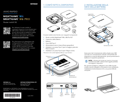
Per caricare la batteria, collegare il cavo USB al router mobile, quindi collegarlo a una presa a muro utilizzando l'adattatore di alimentazione CA o una porta USB del computer.Assicurarsi che l'orientamento della scheda nano SIM coincida con l'orientamento indicato sull'etichetta del dispositivo e inserirla delicatamente, quindi posizionare la batteria e il coperchio posteriore.NOTA: utilizzare solo le dita per inserire o rimuovere la scheda nano SIM. L'utilizzo di altri oggetti potrebbe danneggiare il dispositivo.1. COM'È FATTO IL DISPOSITIVO2. INSTALLAZIONE DELLA SIM E DELLA BATTERIAIl router mobile viene fornito con i seguenti componenti:• Router mobile Nighthawk® M6 o M6 Pro 5G*• Coperchio della batteria • Batteria• Cavo USB Tipo C• Alimentatore (varia in base all’area geografica)• Adattatori con presa Tipo C (per la maggior parte dei Paesi europei)•Adattatori con presa Tipo G (per il Regno Unito)*Illustrazioni del modello Nighthawk M6 per scopi illustrativi.antenna esterna (TS-9)antenna esterna (TS-9)USB Tipo CEthernetCONFORMITÀ NORMATIVA E NOTE LEGALIPer informazioni sulla conformità alle normative, compresala Dichiarazione di conformità UE, visitare il sito Web https:///it/about/regulatory/.Prima di collegare l'alimentazione, consultare il documento relativo alla conformità normativa.Può essere applicato solo ai dispositivi da 6 GHz: utilizzare il dispositivo solo in un ambiente al chiuso. L'utilizzo di dispositivi a 6 GHz è vietato su piattaforme petrolifere, automobili, treni, barche e aerei, tuttavia il suo utilizzo è consentito su aerei di grandi dimensioni quando volano sopra i 3000 metri di altezza. L'utilizzo di trasmettitori nella banda 5.925‑7.125 GHz è vietato per il controllo o le comunicazioni con sistemi aerei senza equipaggio.SUPPORTO E COMMUNITYDalla pagina del portale di amministrazione Web, fare clic sull'icona con i tre puntini nell'angolo in alto a destra per accedere ai file della guida e del supporto.Per ulteriori informazioni, visitare il sito netgear.it/support per accedere al manuale dell'utente completo e per scaricare gli aggiornamenti del firmware.È possibile trovare utili consigli anche nella Community NETGEAR, alla pagina /it.GESTIONE DELLE IMPOSTAZIONI TRAMITE L'APP NETGEAR MOBILEUtilizzare l'app NETGEAR Mobile per modificare il nome della rete Wi-Fi e la password. È possibile utilizzarla anche per riprodurre e condividere contenutimultimediali e accedere alle funzioni avanzate del router mobile.1. Accertarsi che il dispositivo mobile sia connesso a Internet.2. Eseguire la scansione del codice QR per scaricare l'appNETGEAR Mobile.Connessione con il nome e la password della rete Wi-Fi 1. Aprire il programma di gestione della rete Wi‑Fi deldispositivo.2. Individuare il nome della rete Wi‑Fi del router mobile(NTGR_XXXX) e stabilire una connessione.3. Only Connessione tramite EthernetPer prolungare la durata della batteria, l'opzione Ethernet è disattivata per impostazione predefinita. Per attivarla, toccare Power Manager (Risparmio energia) e passare a Performance Mode (Modalità performance).4. CONNESSIONE A INTERNETÈ possibile connettersi a Internet utilizzando il codice QR del router mobile da uno smartphone oppure selezionando manualmente il nome della rete Wi‑Fi del router e immettendo la password.Connessione tramite codice QR da uno smartphone 1. Toccare l'icona del codice QR sulla schermata inizialedello schermo LCD del router mobile.NOTA: quando è inattivo, lo schermo touch si oscura per risparmiare energia. Premere brevemente e rilasciare il pulsante di alimentazione per riattivare lo schermo.3. CONFIGURAZIONE DEL ROUTER MOBILETenere premuto il pulsante di accensione per due secondi, quindi seguire le istruzioni visualizzate sullo schermo per impostare un nome per la rete Wi‑Fi e una password univoci.La personalizzazione delle impostazioni Wi‑Fi consente di proteggere la rete Wi‑Fi del router mobile.Impostazioni APNIl router mobile legge i dati dalla scheda SIM e determina automaticamente le impostazioni APN (Access Point Name) corrette con i piani dati della maggior parte degli operatori. Tuttavia, se si utilizza un router mobile sbloccato con un operatore o un piano meno comune, potrebbe essere necessario immettere manualmente le impostazioni APN.Se viene visualizzata la schermata APN Setup Required (Configurazione APN richiesta), i dati APN dell’operatore non sono presenti nel nostro database ed è necessario inserirli manualmente. Immettere i valori fornitidall’operatore nei campi corrispondenti, quindi toccare Save (Salva) per completare la configurazione.NOTA: l’operatore determina le proprie informazioni APN e deve fornire le informazioni per il proprio piano dati. Si consiglia di contattare il proprio operatore per le impostazioni APN corrette e di utilizzare solo l’APN suggerito per il piano specifico.Schermata inizialeAl termine della configurazione, il router visualizza la schermata iniziale:Wi‑FiPotenza Carica Rete Codice QR connessione rapida Wi‑FiNome e Wi‑FiIcona del codice QR。
E5的CODE对照表

E5的CODE对照表059C438: E5-00 RM-632 3HK HK Black v1059C442: E5-00 RM-632 3HK HK **** v1_COLOR059C291: E5-00 RM-632 Country Variant Hongkong HK (Black v1) 059C2C3: E5-00 RM-632 Country Variant Hongkong HK (**** v1)_COLOR059C437: E5-00 RM-632 Country Variant Thailand TH V1059C648: E5-00 RM-632 Country Variant Thailand TH **** V1_COLOR0595447: RM-632 CTR BLACK APAC QW1 CHINESE PRC ID 0595447: RM-632 CTR BLACK APAC QW1 CHINESE PRC ID 0595447: RM-632 CTR BLACK APAC QW1 CHINESE PRC ID 0595445: RM-632 CTR BLACK APAC QW1 CHINESE PRC KH 0595444: RM-632 CTR BLACK APAC QW1 CHINESE PRC MY马来西亚俗称亚太版颜色是黑色0595443: RM-632 CTR BLACK APAC QW1 CHINESE PRC SG 0595443: RM-632 CTR BLACK APAC QW1 CHINESE PRC SG 0595443: RM-632 CTR BLACK APAC QW1 CHINESE PRC SG 0595443: RM-632 CTR BLACK APAC QW1 CHINESE PRC SG 0595451: RM-632 CTR BLACK APAC QW2 COM ENG B/LK/N 0595451: RM-632 CTR BLACK APAC QW2 COM ENG B/LK/N059B5W2: RM-632 CTR BLACK APAC QW2 COM ENG BD 059B409: RM-632 CTR BLACK APAC QW2 COM ENG Nepal 059B409: RM-632 CTR BLACK APAC QW2 COM ENG Nepal 059B053: RM-632 CTR BLACK APAC QW2 COM ENGLISH AU 059B055: RM-632 CTR BLACK APAC QW2 COM ENGLISH IN 059B055: RM-632 CTR BLACK APAC QW2 COM ENGLISH IN 0595448: RM-632 CTR BLACK APAC QW2 COM ENGLISH NZ 0595446: RM-632 CTR BLACK APAC QW2 COM ENGLISH PH 0592167: RM-632 CTR BLACK CHINA CHINESE PRC CN 0592167: RM-632 CTR BLACK CHINA CHINESE PRC CN 0595458: RM-632 CTR BLACK HONG KONG CHINESE HK HK 0595458: RM-632 CTR BLACK HONG KONG CHINESE HK HK 0595210: RM-632 CTR BLACK MEA1 QW ARABIC LAT J/L 0595210: RM-632 CTR BLACK MEA1 QW ARABIC LAT J/L 0595210: RM-632 CTR BLACK MEA1 QW ARABIC LAT J/L 0595210: RM-632 CTR BLACK MEA1 QW ARABIC LAT J/L 0595225: RM-632 CTR BLACK MEA10 QW FARSI LAT 0595225: RM-632 CTR BLACK MEA10 QW FARSI LAT 0595228: RM-632 CTR BLACK MEA11 QW ARABIC LAT UEA 0595228: RM-632 CTR BLACK MEA11 QW ARABIC LAT UEA 0595228: RM-632 CTR BLACK MEA11 QW ARABIC LAT UEA 0595228: RM-632 CTR BLACK MEA11 QW ARABIC LAT UEA0595231: RM-632 CTR BLACK MEA12 QW COM ENGLISH ZA 0595233: RM-632 CTR BLACK MEA13 QW COM ENG 0595233: RM-632 CTR BLACK MEA13 QW COM ENG 0595233: RM-632 CTR BLACK MEA13 QW COM ENG 0595235: RM-632 CTR BLACK MEA14 QW COM ENGLISH NG 0595235: RM-632 CTR BLACK MEA14 QW COM ENGLISH NG 0595237: RM-632 CTR BLACK MEA15 QW PORTUGUESE 0595237: RM-632 CTR BLACK MEA15 QW PORTUGUESE 0595239: RM-632 CTR BLACK MEA16 QW FRENCH S/I/C/M 0595239: RM-632 CTR BLACK MEA16 QW FRENCH S/I/C/M 0595212: RM-632 CTR BLACK MEA2 QW ARAB LAT KSA/YE 0595212: RM-632 CTR BLACK MEA2 QW ARAB LAT KSA/YE 0595212: RM-632 CTR BLACK MEA2 QW ARAB LAT KSA/YE 0595212: RM-632 CTR BLACK MEA2 QW ARAB LAT KSA/YE 0595216: RM-632 CTR BLACK MEA4 QW ARAB LAT B/Q/O 0595216: RM-632 CTR BLACK MEA4 QW ARAB LAT B/Q/O 0595216: RM-632 CTR BLACK MEA4 QW ARAB LAT B/Q/O 0595216: RM-632 CTR BLACK MEA4 QW ARAB LAT B/Q/O 0595217: RM-632 CTR BLACK MEA5 QW FRENCH DZ/MA/TN 0595217: RM-632 CTR BLACK MEA5 QW FRENCH DZ/MA/TN 0595219: RM-632 CTR BLACK MEA6 QW ARABIC LAT SY 0595219: RM-632 CTR BLACK MEA6 QW ARABIC LAT SY0595222: RM-632 CTR BLACK MEA7 QW COM ENG PK 0595222: RM-632 CTR BLACK MEA7 QW COM ENG PK 0595223: RM-632 CTR BLACK MEA8 QW COM ENG 0595223: RM-632 CTR BLACK MEA8 QW COM ENG 0595223: RM-632 CTR BLACK MEA8 QW COM ENG 0595453: RM-632 CTR BLACK THAI THAI TH0595452: RM-632 CTR BLACK VIETNAM COM ENG VN 0595797: RM-632 CTR **** APAC QW1 CHINESE PRC ID 0595797: RM-632 CTR **** APAC QW1 CHINESE PRC ID 0595797: RM-632 CTR **** APAC QW1 CHINESE PRC ID 0595795: RM-632 CTR **** APAC QW1 CHINESE PRC KH 0595794: RM-632 CTR **** APAC QW1 CHINESE PRC MY 0595791: RM-632 CTR **** APAC QW1 CHINESE PRC SG 0595791: RM-632 CTR **** APAC QW1 CHINESE PRC SG 0595791: RM-632 CTR **** APAC QW1 CHINESE PRC SG 0595791: RM-632 CTR **** APAC QW1 CHINESE PRC SG 0595799: RM-632 CTR **** APAC QW2 COM ENG B/LK/N 0595799: RM-632 CTR **** APAC QW2 COM ENG B/LK/N 059B5W3: RM-632 CTR **** APAC QW2 COM ENG BD 059B5W3: RM-632 CTR **** APAC QW2 COM ENG BD 059B408: RM-632 CTR **** APAC QW2 COM ENG NEPAL 059B408: RM-632 CTR **** APAC QW2 COM ENG NEPAL059B058: RM-632 CTR **** APAC QW2 COM ENGLISH AU 059B059: RM-632 CTR **** APAC QW2 COM ENGLISH IN 059B059: RM-632 CTR **** APAC QW2 COM ENGLISH IN 0595798: RM-632 CTR **** APAC QW2 COM ENGLISH NZ 0595796: RM-632 CTR **** APAC QW2 COM ENGLISH PH 0594888: RM-632 CTR **** CHINA CHINESE PRC CN 0595814: RM-632 CTR **** HONG KONG CHINESE HK HK 0595814: RM-632 CTR **** HONG KONG CHINESE HK HK 0595751: RM-632 CTR **** MEA1 QW ARAB LAT J/L/I 0595751: RM-632 CTR **** MEA1 QW ARAB LAT J/L/I 0595759: RM-632 CTR **** MEA10 QW FARSI LAT 0595759: RM-632 CTR **** MEA10 QW FARSI LAT 0595760: RM-632 CTR **** MEA11 QW ARABIC LAT UEA 0595760: RM-632 CTR **** MEA11 QW ARABIC LAT UEA 0595761: RM-632 CTR **** MEA12 QW COM ENGLISH ZA 0595762: RM-632 CTR **** MEA13 QW COM ENG 0595762: RM-632 CTR **** MEA13 QW COM ENG 0595764: RM-632 CTR **** MEA14 QW COM ENGLISH NG 0595764: RM-632 CTR **** MEA14 QW COM ENGLISH NG 0595765: RM-632 CTR **** MEA15 QW PORTUGUESE 0595765: RM-632 CTR **** MEA15 QW PORTUGUESE 0595766: RM-632 CTR **** MEA16 QW FRENCH0595766: RM-632 CTR **** MEA16 QW FRENCH0595753: RM-632 CTR **** MEA2 QW ARABIC LAT KSA 0595753: RM-632 CTR **** MEA2 QW ARABIC LAT KSA 0595754: RM-632 CTR **** MEA4 QW ARABIC LAT0595754: RM-632 CTR **** MEA4 QW ARABIC LAT0595755: RM-632 CTR **** MEA5 QW FRENCH0595755: RM-632 CTR **** MEA5 QW FRENCH0595756: RM-632 CTR **** MEA6 QW ARABIC LAT0595756: RM-632 CTR **** MEA6 QW ARABIC LAT0595757: RM-632 CTR **** MEA7 QW COM ENG PK 0595757: RM-632 CTR **** MEA7 QW COM ENG PK 0595758: RM-632 CTR **** MEA8 QW COM ENG0595758: RM-632 CTR **** MEA8 QW COM ENG0595802: RM-632 CTR **** THAI THAI TH0595800: RM-632 CTR **** VIETNAM COM ENG VN059C368: E5-00 RM-632 Country Variant Croatia HR Black v1 059C209: E5-00 RM-632 Country Variant United Kingdom GB V1 Black059C2Z9: E5-00 RM-632 Orange Romania RO GV。
EPCOS AG数据和信号线滤波器说明书

Data and signal line chokesCommon-mode chokes, ring core0.005 … 47 mH, 100 … 1200 mA, +60 °CSeries/Type:B82793C0/S0Date:March 2016¤ EPCOS AG 2016. Reproduction, publication and dissemination of this publication, enclosures hereto and the information contained therein without EPCOS’ prior express consent is prohibited.EPCOS AG is a TDK Group Company.Rated voltage 42 V AC/80 V DC Rated inductance 0.005 ... 47 mH Rated current 100 ... 1200 mA Construction■Current-compensated double choke ■Ferrite core■LCP case (UL 94 V-0), silicone potting ■Bifilar winding (B82793C0)■Sector winding (B82793S0)Features■High rated currents, reduced components height ■Qualified to AEC-Q200 (L d 4.7 mH)■Suitable for reflow soldering ■RoHS-compatibleFunction■B82793C0:Suppression of asymmetrical interference coupled in on lines,whereas data signals up to some MHz can pass unaffectedly.■B82793S0:Suppression of asymmetrical and symmetrical interference (by L stray )coupled in on lines. The high-frequency portions of the symmetrical data signal are decreased so far that EMC problems can be significantly reduced.Applications■Automotive applications, e.g. CAN bus ■Industrial applications■Types with L R ! 4.7 mH only for telecom applicationsTerminals■Base material CuSn6■Layer composition Ni, Sn ■Hot-dippedMarking■Marking on component: Manufacturer, process location (coded),winding method (coded),ordering code (short form), date of manufacture (YWWD)■Minimum data on reel: Manufacturer, ordering code,L value and tolerance, quantity, date of packing Delivery mode and packing unit■16-mm blister tape, wound on 330-mm reel ■Packing unit: 1500 pcs./reel Common-mode chokes, ring coreDimensional drawing and pin configurationLayout recommendationTaping and packing Blister tapeReelDimensions in mmDimensions in mmCommon-mode chokes, ring coreCommon-mode chokes, ring coreTechnical data and measuring conditionsRated voltage V R42 V AC (50/60 Hz) / 80 V DCRated temperature T R+60 °CRated current I R Referred to 50 Hz and rated temperatureRated inductance L R Measured with Agilent 4284A, 0.1 mA, +20 °CMeasuring frequency:L R d 1 mH = 100 kHzL R! 1 mH = 10 kHzInductance is specified per winding.Inductance tolerance r30% (L R d0.47mH), –30/+50% (L R t1mH) at +20 °C Inductance decrease 'L/L 10% at DC magnetic bias with I R, +20 °CStray inductance L stray,typ Measured with Agilent 4284A, 5 mA, +20 °C, typical valuesMeasuring frequency:L R d 11P H = 1 MHzL R! 11P H = 100 kHzDC resistance R typ Measured at +20q C, typical values, specified per winding Solderability SnPb:+(215 r3) °C, (3 r0.3) sSn96.5Ag3.0Cu0.5:+(245 r5) °C, (3 r0.3) sWetting of soldering area t 95%(to IEC 60068-2-58)Resistance to soldering heat+(260 r5) °C, (10 r1) s (to IEC 60068-2-58)Climatic category 40/125/56 (to IEC 60068-1)Storage conditions (packaged)–25 °C … +40 °C, d 75% RHWeight Approx. 0.25 gCharacteristics and ordering codesL R mH L stray,typnHI RmAR typm:V testV DC, 2 sOrdering code0.005 40120060250B82793C0502N201 0.011 50 80080250B82793C0113N201 0.02560 800110250B82793C0253N201 0.0251400 800110250B82793S0253N201 0.05170 800140250B82793C0513N201 0.0512300 800140250B82793S0513N201 0.10 100 500180250B82793C0104N2010.47 100 700170750B82793C0474N2151.070 700140750B82793C0105N2652.2 120 500400750B82793C0225N265 4.7 250 400550750B82793C0475N265 For telecommunications203001001800750B82793C0206N265 4712001003700750B82793C0476N265 Common-mode chokes, ring coreInsertion loss D (typical values at |Z| = 50 :, +20 °C)asymmetrical, all branches in parallel (common mode)symmetrical (differential mode)L R = 0.005 mHL R = 0.025 mH (low L stray)L R = 0.011 mHL R = 0.025 mH (high L stray) Common-mode chokes, ring coreInsertion loss D (typical values at |Z| = 50 :, +20 °C)asymmetrical, all branches in parallel (common mode)symmetrical (differential mode)L R = 0.051 mH (low L stray) L R = 0.10 mH L R = 0.051 mH (high L stray) L R= 0.47 mH Common-mode chokes, ring coreInsertion loss D (typical values at |Z| = 50 :, +20 °C)asymmetrical, all branches in parallel (common mode)symmetrical (differential mode)L R =1.0 mH L R = 4.7 mH L R = 2.2 mH L R= 20 mH Common-mode chokes, ring coreInsertion loss D (typical values at |Z| = 50 :, +20 °C)asymmetrical, all branches in parallel (common mode)symmetrical (differential mode)L R = 47 mHCurrent derating I op /I Rversus ambient temperatureCommon-mode chokes, ring coreRecommended reflow soldering curvePb containing solder material (based on CECC 00802 edition 2)Pb-free solder material (based on JEDEC J-STD 020D)Time from +25 °C to T 4: max 300 s Maximal numbers of reflow cycles: 3T 1°C T 2°C T 3°C T 4°C t 1s t 2s t 3s150200217250< 110< 90< 40 @ T 4–5 °CCommon-mode chokes, ring core■Please note the recommendations in our Inductors data book (latest edition) and in the data sheets.–Particular attention should be paid to the derating curves given there.–The soldering conditions should also be observed. Temperatures quoted in relation to wave soldering refer to the pin, not the housing.■If the components are to be washed varnished it is necessary to check whether the washing varnish agent that is used has a negative effect on the wire insulation, any plastics that are used, or on glued joints. In particular, it is possible for washing varnish agent residues to have a negative effect in the long-term on wire insulation.Washing processes may damage the product due to the possible static or cyclic mechanical loads (e.g. ultrasonic cleaning). They may cause cracks to develop on the product and its parts, which might lead to reduced reliability or lifetime.■The following points must be observed if the components are potted in customer applications: –Many potting materials shrink as they harden. They therefore exert a pressure on the plastic housing or core. This pressure can have a deleterious effect on electrical properties, and in extreme cases can damage the core or plastic housing mechanically.–It is necessary to check whether the potting material used attacks or destroys the wire insulation, plastics or glue.–The effect of the potting material can change the high-frequency behaviour of the components.■Ferrites are sensitive to direct impact. This can cause the core material to flake, or lead to breakage of the core.■Even for customer-specific products, conclusive validation of the component in the circuit can only be carried out by the customer.Display of ordering codes for EPCOS productsThe ordering code for one and the same product can be represented differently in data sheets, data books, other publications and the website of EPCOS, or in order-related documents such as shipping notes, order confirmations and product labels. The varying representations of the ordering codes are due to different processes employed and do not affect the specifications of the respective products. Detailed information can be found on the Internet under /orderingcodes.Please read Cautions and warnings and1103/16Important notes at the end of this document.Important notesThe following applies to all products named in this publication:1.Some parts of this publication contain statements about the suitability of our products for certain areasof application. These statements are based on our knowledge of typical requirements that are often placed on our products in the areas of application concerned. We nevertheless expressly point out that such statements cannot be regarded as binding statements about the suitability of our products for a particular customer application. As a rule we are either unfamiliar with individual customer applications or less familiar with them than the customers themselves. For these reasons, it is always ultimately incumbent on the customer to check and decide whether a product with the properties described in the product specification is suitable for use in a particular customer application.2.We also point out that in individual cases, a malfunction of electronic components or failure beforethe end of their usual service life cannot be completely ruled out in the current state of the art, even if they are operated as specified. In customer applications requiring a very high level of operational safety and especially in customer applications in which the malfunction or failure of an electronic component could endanger human life or health (e.g. in accident prevention or life-saving systems), it must therefore be ensured by means of suitable design of the customer application or other action taken by the customer (e.g.installation of protective circuitry or redundancy) that no injury or damage is sustained by third parties in the event of malfunction or failure of an electronic component.3.The warnings, cautions and product-specific notes must be observed.4.In order to satisfy certain technical requirements, some of the products described in this publicationmay contain substances subject to restrictions in certain jurisdictions (e.g. because they are classed as hazardous). Useful information on this will be found in our Material Data Sheets on the Internet (/material). Should you have any more detailed questions, please contact our sales offices.5.We constantly strive to improve our products. Consequently, the products described in this publicationmay change from time to time. The same is true of the corresponding product specifications. Please check therefore to what extent product descriptions and specifications contained in this publication are still applicable before or when you place an order.We also reserve the right to discontinue production and delivery of products. Consequently, we cannot guarantee that all products named in this publication will always be available. The aforementioned does not apply in the case of individual agreements deviating from the foregoing for customer-specific products.6.Unless otherwise agreed in individual contracts, all orders are subject to our General Terms andConditions of Supply.7.Our manufacturing sites serving the automotive business apply the IATF 16949 standard. The IATFcertifications confirm our compliance with requirements regarding the quality management system in the automotive industry. Referring to customer requirements and customer specific requirements (“CSR”) TDK always has and will continue to have the policy of respecting individual agreements. Even if IATF 16949 may appear to support the acceptance of unilateral requirements, we hereby like to emphasize that only requirements mutually agreed upon can and will be implemented in our Quality Management System. For clarification purposes we like to point out that obligations from IATF 16949 shall only become legally binding if individually agreed upon.8.The trade names EPCOS, CeraCharge, CeraDiode, CeraLink, CeraPad, CeraPlas, CSMP, CTVS,DeltaCap, DigiSiMic, ExoCore, FilterCap, FormFit, LeaXield, MiniBlue, MiniCell, MKD, MKK, MotorCap, PCC, PhaseCap, PhaseCube, PhaseMod, PhiCap, PowerHap, PQSine, PQvar, SIFERRIT, SIFI, SIKOREL, SilverCap, SIMDAD, SiMic, SIMID, SineFormer, SIOV, ThermoFuse, WindCap are trademarks registered or pending in Europe and in other countries. Further information will be found on the Internet at /trademarks.Release 2018-101203/16。
jstd035声学扫描

JOINT INDUSTRY STANDARDAcoustic Microscopy for Non-HermeticEncapsulatedElectronicComponents IPC/JEDEC J-STD-035APRIL1999Supersedes IPC-SM-786 Supersedes IPC-TM-650,2.6.22Notice EIA/JEDEC and IPC Standards and Publications are designed to serve thepublic interest through eliminating misunderstandings between manufacturersand purchasers,facilitating interchangeability and improvement of products,and assisting the purchaser in selecting and obtaining with minimum delaythe proper product for his particular need.Existence of such Standards andPublications shall not in any respect preclude any member or nonmember ofEIA/JEDEC or IPC from manufacturing or selling products not conformingto such Standards and Publications,nor shall the existence of such Standardsand Publications preclude their voluntary use by those other than EIA/JEDECand IPC members,whether the standard is to be used either domestically orinternationally.Recommended Standards and Publications are adopted by EIA/JEDEC andIPC without regard to whether their adoption may involve patents on articles,materials,or processes.By such action,EIA/JEDEC and IPC do not assumeany liability to any patent owner,nor do they assume any obligation whateverto parties adopting the Recommended Standard or ers are alsowholly responsible for protecting themselves against all claims of liabilities forpatent infringement.The material in this joint standard was developed by the EIA/JEDEC JC-14.1Committee on Reliability Test Methods for Packaged Devices and the IPCPlastic Chip Carrier Cracking Task Group(B-10a)The J-STD-035supersedes IPC-TM-650,Test Method2.6.22.For Technical Information Contact:Electronic Industries Alliance/ JEDEC(Joint Electron Device Engineering Council)2500Wilson Boulevard Arlington,V A22201Phone(703)907-7560Fax(703)907-7501IPC2215Sanders Road Northbrook,IL60062-6135 Phone(847)509-9700Fax(847)509-9798Please use the Standard Improvement Form shown at the end of thisdocument.©Copyright1999.The Electronic Industries Alliance,Arlington,Virginia,and IPC,Northbrook,Illinois.All rights reserved under both international and Pan-American copyright conventions.Any copying,scanning or other reproduction of these materials without the prior written consent of the copyright holder is strictly prohibited and constitutes infringement under the Copyright Law of the United States.IPC/JEDEC J-STD-035Acoustic Microscopyfor Non-Hermetic EncapsulatedElectronicComponentsA joint standard developed by the EIA/JEDEC JC-14.1Committee on Reliability Test Methods for Packaged Devices and the B-10a Plastic Chip Carrier Cracking Task Group of IPCUsers of this standard are encouraged to participate in the development of future revisions.Contact:EIA/JEDEC Engineering Department 2500Wilson Boulevard Arlington,V A22201 Phone(703)907-7500 Fax(703)907-7501IPC2215Sanders Road Northbrook,IL60062-6135 Phone(847)509-9700Fax(847)509-9798ASSOCIATION CONNECTINGELECTRONICS INDUSTRIESAcknowledgmentMembers of the Joint IPC-EIA/JEDEC Moisture Classification Task Group have worked to develop this document.We would like to thank them for their dedication to this effort.Any Standard involving a complex technology draws material from a vast number of sources.While the principal members of the Joint Moisture Classification Working Group are shown below,it is not possible to include all of those who assisted in the evolution of this Standard.To each of them,the mem-bers of the EIA/JEDEC and IPC extend their gratitude.IPC Packaged Electronic Components Committee ChairmanMartin FreedmanAMP,Inc.IPC Plastic Chip Carrier Cracking Task Group,B-10a ChairmanSteven MartellSonoscan,Inc.EIA/JEDEC JC14.1CommitteeChairmanJack McCullenIntel Corp.EIA/JEDEC JC14ChairmanNick LycoudesMotorolaJoint Working Group MembersCharlie Baker,TIChristopher Brigham,Hi/FnRalph Carbone,Hewlett Packard Co. Don Denton,TIMatt Dotty,AmkorMichele J.DiFranza,The Mitre Corp. Leo Feinstein,Allegro Microsystems Inc.Barry Fernelius,Hewlett Packard Co. Chris Fortunko,National Institute of StandardsRobert J.Gregory,CAE Electronics, Inc.Curtis Grosskopf,IBM Corp.Bill Guthrie,IBM Corp.Phil Johnson,Philips Semiconductors Nick Lycoudes,MotorolaSteven R.Martell,Sonoscan Inc. Jack McCullen,Intel Corp.Tom Moore,TIDavid Nicol,Lucent Technologies Inc.Pramod Patel,Advanced Micro Devices Inc.Ramon R.Reglos,XilinxCorazon Reglos,AdaptecGerald Servais,Delphi Delco Electronics SystemsRichard Shook,Lucent Technologies Inc.E.Lon Smith,Lucent Technologies Inc.Randy Walberg,NationalSemiconductor Corp.Charlie Wu,AdaptecEdward Masami Aoki,HewlettPackard LaboratoriesFonda B.Wu,Raytheon Systems Co.Richard W.Boerdner,EJE ResearchVictor J.Brzozowski,NorthropGrumman ES&SDMacushla Chen,Wus Printed CircuitCo.Ltd.Jeffrey C.Colish,Northrop GrummanCorp.Samuel J.Croce,Litton AeroProducts DivisionDerek D-Andrade,Surface MountTechnology CentreRao B.Dayaneni,Hewlett PackardLaboratoriesRodney Dehne,OEM WorldwideJames F.Maguire,Boeing Defense&Space GroupKim Finch,Boeing Defense&SpaceGroupAlelie Funcell,Xilinx Inc.Constantino J.Gonzalez,ACMEMunir Haq,Advanced Micro DevicesInc.Larry A.Hargreaves,DC.ScientificInc.John T.Hoback,Amoco ChemicalCo.Terence Kern,Axiom Electronics Inc.Connie M.Korth,K-Byte/HibbingManufacturingGabriele Marcantonio,NORTELCharles Martin,Hewlett PackardLaboratoriesRichard W.Max,Alcatel NetworkSystems Inc.Patrick McCluskey,University ofMarylandJames H.Moffitt,Moffitt ConsultingServicesRobert Mulligan,Motorola Inc.James E.Mumby,CibaJohn Northrup,Lockheed MartinCorp.Dominique K.Numakura,LitchfieldPrecision ComponentsNitin B.Parekh,Unisys Corp.Bella Poborets,Lucent TechnologiesInc.D.Elaine Pope,Intel Corp.Ray Prasad,Ray Prasad ConsultancyGroupAlbert Puah,Adaptec Inc.William Sepp,Technic Inc.Ralph W.Taylor,Lockheed MartinCorp.Ed R.Tidwell,DSC CommunicationsCorp.Nick Virmani,Naval Research LabKen Warren,Corlund ElectronicsCorp.Yulia B.Zaks,Lucent TechnologiesInc.IPC/JEDEC J-STD-035April1999 iiTable of Contents1SCOPE (1)2DEFINITIONS (1)2.1A-mode (1)2.2B-mode (1)2.3Back-Side Substrate View Area (1)2.4C-mode (1)2.5Through Transmission Mode (2)2.6Die Attach View Area (2)2.7Die Surface View Area (2)2.8Focal Length(FL) (2)2.9Focus Plane (2)2.10Leadframe(L/F)View Area (2)2.11Reflective Acoustic Microscope (2)2.12Through Transmission Acoustic Microscope (2)2.13Time-of-Flight(TOF) (3)2.14Top-Side Die Attach Substrate View Area (3)3APPARATUS (3)3.1Reflective Acoustic Microscope System (3)3.2Through Transmission AcousticMicroscope System (4)4PROCEDURE (4)4.1Equipment Setup (4)4.2Perform Acoustic Scans..........................................4Appendix A Acoustic Microscopy Defect CheckSheet (6)Appendix B Potential Image Pitfalls (9)Appendix C Some Limitations of AcousticMicroscopy (10)Appendix D Reference Procedure for PresentingApplicable Scanned Data (11)FiguresFigure1Example of A-mode Display (1)Figure2Example of B-mode Display (1)Figure3Example of C-mode Display (2)Figure4Example of Through Transmission Display (2)Figure5Diagram of a Reflective Acoustic MicroscopeSystem (3)Figure6Diagram of a Through Transmission AcousticMicroscope System (3)April1999IPC/JEDEC J-STD-035iiiIPC/JEDEC J-STD-035April1999This Page Intentionally Left BlankivApril1999IPC/JEDEC J-STD-035 Acoustic Microscopy for Non-Hermetic EncapsulatedElectronic Components1SCOPEThis test method defines the procedures for performing acoustic microscopy on non-hermetic encapsulated electronic com-ponents.This method provides users with an acoustic microscopy processflow for detecting defects non-destructively in plastic packages while achieving reproducibility.2DEFINITIONS2.1A-mode Acoustic data collected at the smallest X-Y-Z region defined by the limitations of the given acoustic micro-scope.An A-mode display contains amplitude and phase/polarity information as a function of time offlight at a single point in the X-Y plane.See Figure1-Example of A-mode Display.IPC-035-1 Figure1Example of A-mode Display2.2B-mode Acoustic data collected along an X-Z or Y-Z plane versus depth using a reflective acoustic microscope.A B-mode scan contains amplitude and phase/polarity information as a function of time offlight at each point along the scan line.A B-mode scan furnishes a two-dimensional(cross-sectional)description along a scan line(X or Y).See Figure2-Example of B-mode Display.IPC-035-2 Figure2Example of B-mode Display(bottom half of picture on left)2.3Back-Side Substrate View Area(Refer to Appendix A,Type IV)The interface between the encapsulant and the back of the substrate within the outer edges of the substrate surface.2.4C-mode Acoustic data collected in an X-Y plane at depth(Z)using a reflective acoustic microscope.A C-mode scan contains amplitude and phase/polarity information at each point in the scan plane.A C-mode scan furnishes a two-dimensional(area)image of echoes arising from reflections at a particular depth(Z).See Figure3-Example of C-mode Display.1IPC/JEDEC J-STD-035April1999IPC-035-3 Figure3Example of C-mode Display2.5Through Transmission Mode Acoustic data collected in an X-Y plane throughout the depth(Z)using a through trans-mission acoustic microscope.A Through Transmission mode scan contains only amplitude information at each point in the scan plane.A Through Transmission scan furnishes a two-dimensional(area)image of transmitted ultrasound through the complete thickness/depth(Z)of the sample/component.See Figure4-Example of Through Transmission Display.IPC-035-4 Figure4Example of Through Transmission Display2.6Die Attach View Area(Refer to Appendix A,Type II)The interface between the die and the die attach adhesive and/or the die attach adhesive and the die attach substrate.2.7Die Surface View Area(Refer to Appendix A,Type I)The interface between the encapsulant and the active side of the die.2.8Focal Length(FL)The distance in water at which a transducer’s spot size is at a minimum.2.9Focus Plane The X-Y plane at a depth(Z),which the amplitude of the acoustic signal is maximized.2.10Leadframe(L/F)View Area(Refer to Appendix A,Type V)The imaged area which extends from the outer L/F edges of the package to the L/F‘‘tips’’(wedge bond/stitch bond region of the innermost portion of the L/F.)2.11Reflective Acoustic Microscope An acoustic microscope that uses one transducer as both the pulser and receiver. (This is also known as a pulse/echo system.)See Figure5-Diagram of a Reflective Acoustic Microscope System.2.12Through Transmission Acoustic Microscope An acoustic microscope that transmits ultrasound completely through the sample from a sending transducer to a receiver on the opposite side.See Figure6-Diagram of a Through Transmis-sion Acoustic Microscope System.2April1999IPC/JEDEC J-STD-0353IPC/JEDEC J-STD-035April1999 3.1.6A broad band acoustic transducer with a center frequency in the range of10to200MHz for subsurface imaging.3.2Through Transmission Acoustic Microscope System(see Figure6)comprised of:3.2.1Items3.1.1to3.1.6above3.2.2Ultrasonic pulser(can be a pulser/receiver as in3.1.1)3.2.3Separate receiving transducer or ultrasonic detection system3.3Reference packages or standards,including packages with delamination and packages without delamination,for use during equipment setup.3.4Sample holder for pre-positioning samples.The holder should keep the samples from moving during the scan and maintain planarity.4PROCEDUREThis procedure is generic to all acoustic microscopes.For operational details related to this procedure that apply to a spe-cific model of acoustic microscope,consult the manufacturer’s operational manual.4.1Equipment Setup4.1.1Select the transducer with the highest useable ultrasonic frequency,subject to the limitations imposed by the media thickness and acoustic characteristics,package configuration,and transducer availability,to analyze the interfaces of inter-est.The transducer selected should have a low enough frequency to provide a clear signal from the interface of interest.The transducer should have a high enough frequency to delineate the interface of interest.Note:Through transmission mode may require a lower frequency and/or longer focal length than reflective mode.Through transmission is effective for the initial inspection of components to determine if defects are present.4.1.2Verify setup with the reference packages or standards(see3.3above)and settings that are appropriate for the trans-ducer chosen in4.1.1to ensure that the critical parameters at the interface of interest correlate to the reference standard uti-lized.4.1.3Place units in the sample holder in the coupling medium such that the upper surface of each unit is parallel with the scanning plane of the acoustic transducer.Sweep air bubbles away from the unit surface and from the bottom of the trans-ducer head.4.1.4At afixed distance(Z),align the transducer and/or stage for the maximum reflected amplitude from the top surface of the sample.The transducer must be perpendicular to the sample surface.4.1.5Focus by maximizing the amplitude,in the A-mode display,of the reflection from the interface designated for imag-ing.This is done by adjusting the Z-axis distance between the transducer and the sample.4.2Perform Acoustic Scans4.2.1Inspect the acoustic image(s)for any anomalies,verify that the anomaly is a package defect or an artifact of the imaging process,and record the results.(See Appendix A for an example of a check sheet that may be used.)To determine if an anomaly is a package defect or an artifact of the imaging process it is recommended to analyze the A-mode display at the location of the anomaly.4.2.2Consider potential pitfalls in image interpretation listed in,but not limited to,Appendix B and some of the limita-tions of acoustic microscopy listed in,but not limited to,Appendix C.If necessary,make adjustments to the equipment setup to optimize the results and rescan.4April1999IPC/JEDEC J-STD-035 4.2.3Evaluate the acoustic images using the failure criteria specified in other appropriate documents,such as J-STD-020.4.2.4Record the images and thefinal instrument setup parameters for documentation purposes.An example checklist is shown in Appendix D.5IPC/JEDEC J-STD-035April19996April1999IPC/JEDEC J-STD-035Appendix AAcoustic Microscopy Defect Check Sheet(continued)CIRCUIT SIDE SCANImage File Name/PathDelamination(Type I)Die Circuit Surface/Encapsulant Number Affected:Average%Location:Corner Edge Center (Type II)Die/Die Attach Number Affected:Average%Location:Corner Edge Center (Type III)Encapsulant/Substrate Number Affected:Average%Location:Corner Edge Center (Type V)Interconnect tip Number Affected:Average%Interconnect Number Affected:Max.%Length(Type VI)Intra-Laminate Number Affected:Average%Location:Corner Edge Center Comments:CracksAre cracks present:Yes NoIf yes:Do any cracks intersect:bond wire ball bond wedge bond tab bump tab leadDoes crack extend from leadfinger to any other internal feature:Yes NoDoes crack extend more than two-thirds the distance from any internal feature to the external surfaceof the package:Yes NoAdditional verification required:Yes NoComments:Mold Compound VoidsAre voids present:Yes NoIf yes:Approx.size Location(if multiple voids,use comment section)Do any voids intersect:bond wire ball bond wedge bond tab bump tab lead Additional verification required:Yes NoComments:7IPC/JEDEC J-STD-035April1999Appendix AAcoustic Microscopy Defect Check Sheet(continued)NON-CIRCUIT SIDE SCANImage File Name/PathDelamination(Type IV)Encapsulant/Substrate Number Affected:Average%Location:Corner Edge Center (Type II)Substrate/Die Attach Number Affected:Average%Location:Corner Edge Center (Type V)Interconnect Number Affected:Max.%LengthLocation:Corner Edge Center (Type VI)Intra-Laminate Number Affected:Average%Location:Corner Edge Center (Type VII)Heat Spreader Number Affected:Average%Location:Corner Edge Center Additional verification required:Yes NoComments:CracksAre cracks present:Yes NoIf yes:Does crack extend more than two-thirds the distance from any internal feature to the external surfaceof the package:Yes NoAdditional verification required:Yes NoComments:Mold Compound VoidsAre voids present:Yes NoIf yes:Approx.size Location(if multiple voids,use comment section)Additional verification required:Yes NoComments:8Appendix BPotential Image PitfallsOBSERV ATIONS CAUSES/COMMENTSUnexplained loss of front surface signal Gain setting too lowSymbolization on package surfaceEjector pin knockoutsPin1and other mold marksDust,air bubbles,fingerprints,residueScratches,scribe marks,pencil marksCambered package edgeUnexplained loss of subsurface signal Gain setting too lowTransducer frequency too highAcoustically absorbent(rubbery)fillerLarge mold compound voidsPorosity/high concentration of small voidsAngled cracks in package‘‘Dark line boundary’’(phase cancellation)Burned molding compound(ESD/EOS damage)False or spotty indication of delamination Low acoustic impedance coating(polyimide,gel)Focus errorIncorrect delamination gate setupMultilayer interference effectsFalse indication of adhesion Gain set too high(saturation)Incorrect delamination gate setupFocus errorOverlap of front surface and subsurface echoes(transducerfrequency too low)Fluidfilling delamination areasApparent voiding around die edge Reflection from wire loopsIncorrect setting of void gateGraded intensity Die tilt or lead frame deformation Sample tiltApril1999IPC/JEDEC J-STD-0359Appendix CSome Limitations of Acoustic MicroscopyAcoustic microscopy is an analytical technique that provides a non-destructive method for examining plastic encapsulated components for the existence of delaminations,cracks,and voids.This technique has limitations that include the following: LIMITATION REASONAcoustic microscopy has difficulty infinding small defects if the package is too thick.The ultrasonic signal becomes more attenuated as a function of two factors:the depth into the package and the transducer fre-quency.The greater the depth,the greater the attenuation.Simi-larly,the higher the transducer frequency,the greater the attenu-ation as a function of depth.There are limitations on the Z-axis(axial)resolu-tion.This is a function of the transducer frequency.The higher the transducer frequency,the better the resolution.However,the higher frequency signal becomes attenuated more quickly as a function of depth.There are limitations on the X-Y(lateral)resolu-tion.The X-Y(lateral)resolution is a function of a number of differ-ent variables including:•Transducer characteristics,including frequency,element diam-eter,and focal length•Absorption and scattering of acoustic waves as a function of the sample material•Electromechanical properties of the X-Y stageIrregularly shaped packages are difficult to analyze.The technique requires some kind offlat reference surface.Typically,the upper surface of the package or the die surfacecan be used as references.In some packages,cambered packageedges can cause difficulty in analyzing defects near the edgesand below their surfaces.Edge Effect The edges cause difficulty in analyzing defects near the edge ofany internal features.IPC/JEDEC J-STD-035April1999 10April1999IPC/JEDEC J-STD-035Appendix DReference Procedure for Presenting Applicable Scanned DataMost of the settings described may be captured as a default for the particular supplier/product with specific changes recorded on a sample or lot basis.Setup Configuration(Digital Setup File Name and Contents)Calibration Procedure and Calibration/Reference Standards usedTransducerManufacturerModelCenter frequencySerial numberElement diameterFocal length in waterScan SetupScan area(X-Y dimensions)Scan step sizeHorizontalVerticalDisplayed resolutionHorizontalVerticalScan speedPulser/Receiver SettingsGainBandwidthPulseEnergyRepetition rateReceiver attenuationDampingFilterEcho amplitudePulse Analyzer SettingsFront surface gate delay relative to trigger pulseSubsurface gate(if used)High passfilterDetection threshold for positive oscillation,negative oscillationA/D settingsSampling rateOffset settingPer Sample SettingsSample orientation(top or bottom(flipped)view and location of pin1or some other distinguishing characteristic) Focus(point,depth,interface)Reference planeNon-default parametersSample identification information to uniquely distinguish it from others in the same group11IPC/JEDEC J-STD-035April1999Appendix DReference Procedure for Presenting Applicable Scanned Data(continued) Reference Procedure for Presenting Scanned DataImagefile types and namesGray scale and color image legend definitionsSignificance of colorsIndications or definition of delaminationImage dimensionsDepth scale of TOFDeviation from true aspect ratioImage type:A-mode,B-mode,C-mode,TOF,Through TransmissionA-mode waveforms should be provided for points of interest,such as delaminated areas.In addition,an A-mode image should be provided for a bonded area as a control.12Standard Improvement FormIPC/JEDEC J-STD-035The purpose of this form is to provide the Technical Committee of IPC with input from the industry regarding usage of the subject standard.Individuals or companies are invited to submit comments to IPC.All comments will be collected and dispersed to the appropriate committee(s).If you can provide input,please complete this form and return to:IPC2215Sanders RoadNorthbrook,IL 60062-6135Fax 847509.97981.I recommend changes to the following:Requirement,paragraph number Test Method number,paragraph numberThe referenced paragraph number has proven to be:Unclear Too RigidInErrorOther2.Recommendations forcorrection:3.Other suggestions for document improvement:Submitted by:Name Telephone Company E-mailAddress City/State/ZipDate ASSOCIATION CONNECTING ELECTRONICS INDUSTRIESASSOCIATION CONNECTINGELECTRONICS INDUSTRIESISBN#1-580982-28-X2215 Sanders Road, Northbrook, IL 60062-6135Tel. 847.509.9700 Fax 847.509.9798。
Canon EOS Rebel T3I 数码相机产品说明书
E378Follow us!Our Sales Pros will provide you with the solutions you need.•18 Megapixel CMOS APS-C sensor withDIGIC 4 Image Processor, 14-bit A/D conversion•EOS Full HD Movie mode records 1920x1080 resolution •21.1 Megapixel full-frame CMOS sensor, •Full HD video capture at 1920x1080 resolution, up to ......16GB SanDisk Extreme III CF card (30MB/sec) ..156.54 Standard Zoom2042B002 ..............EF-S 18–55mm f/3.5–5.6 IS ....................9517A002...............EF-S 17–85mm f/4–5.6 IS USM ...............Telephoto Zoom1258B002 ..............EF 70-200mm f/4L IS USM CANON EOS (SLR) LENSESEF 400MM F/5.6L•18.0 Megapixel CMOS Sensor & Dual DIGIC 4 Image Processors •0.1 second Light Speed auto-focus•3" LCD touch screen that flips out and rotates 270°...........DSLR camera w/18-55mm f/3.5-5.6 lens, black.............649.99LUMIX MICRO sor, Translucent Mirror Technology™•Canon 1.5-inch, 14.3 MP CMOS sensor with the DIGIC 5 Image Processor for low-light performance up to ISO 12800 •Shooting and recording modes includestunning images from up close or at a distance379IKAN CAMERA STABILIZATION SYSTEM This is a shooting platform for a HDSLR or prosumer video camera. This molded composite tool has a low reachingshoulder pad for added stability and an adjustable chest brace for support. The included Rod Mount Adapter and strategically placed receiver slots allow for a variety of accessory mounting options including a small monitor or on-camera light. The Recoil-XT evenly distributes the camera weight (up to 8lbs) and is compatible with any 15mm rod system.ITEM DESC R IPTION P R ICE ELE-RECOIL-XT ..........Camera stabilization system w/15mm rods and shoulder pad ...314.10GENUS SHOULDER M OUNT SYSTEM The GCSMK system provides balance and stability during a shoot. It is a modular system that can be built to individual requirements and features comfortable non-slip handlesand parts that can be flipped to suit different cameras and camcorders.ITEM DESC R IPTION P R ICE GCSMK ......................Shoulder mount system ...............................................................949.89retracting two position, goat’s hair brush, white microfiber cloth, small Rocket Blaster, M ANFROTTO PHOTO-M OVIE CARBON FIBER TRIPOD KIT Kit includes MH055M8-Q5 photo video head and 755CX3 tripod. Head is made of magnesium and features a repositionable pan bar, photo-movie selector switch, adjustable friction control, independent pan lock, adjustable counterbalance, and a single tilt/portrait orientation lock. The head's fluid cartridge offers high precision and control 755CX3-M8Q5 ...........2-stage carbon fiber tripod & photo/video head .........................779.89It’s a tripod and monopod in one. One leg of the tripod combined with the center column converts to a monopod that can be expanded up to 68". The legs are made of carbon fiber or aluminum and feature Giotto's SDL dust-proof locking system with 1/8" turn leg locks. They also feature rubber feet w/metal spike (on some models), bubble level & retractable hook. The included quick-release ballhead has bubble levels and is Arca-compatible. Every kit also IKAN ELEM ENTS M ODULAR CA M ERA SUPPORT KITS These easy-to-assemble kits are designed to provide camera support that is light-weight, comfortable, and inexpensive. Designed to combine the convenience of a flash bracket allowing you to mount a monitor, light, flash or mic on either side. The Flyer is not as heavy or cumbersome as afull rod system. Developed with DSLRs in mind and the handles will not block your HDMI connections. The kits are compatible with all 15mm rail systems.ITEM DESC R IPTION P R ICE ELE-FLY-STARTER .....Starter kit, cheese plate, 1 handle, 1 arm ...................................109.00ELE-FLY-BASIC .........Basic kit, cheese plate, 2 handles, 2 arms .................................129.00ELE-FLY-DELUXE .......Deluxe kit, cheese plate, 2 handles, 2 arms, 2 4" rods & mount ...249.00ELE-FLY-SUPER ........Super kit, 2 cheese plates, 2 grip bars, 4 arms,2 15mm 6" rods, 15mm rail mount .............................................399.00CAMERANOT INCLUDEDKT1500U KT800U KT900GEPE CARDSAFE The CardSafeholders feature 3 or 4 multi-card compartments made with an anti-static inner material and are shock-resistant, dust and weatherproof and float. The CardSafe Extreme is also crushproof, watertight and has an ergonomic lock andreinforced hinge. Available in black or neon yellow. ITEM DESC R IPTION P R ICE3861E ........................Fits CF, SD, MMC, Memory Stick and Smart Media cards, black ......28.993862E ........................Same as above, neon yellow ..........................................................28.993853..........................Fits SD, MMC, Memory Stick Duo, SD-Mini, XD, black ...................20.993854..........................Same as above, neon yellow ..........................................................20.99CARDSAFEEXTREME KT1500U VGR8255-S2CKSB-1250。
中华美文韵脚全集(24词韵403拼音)-严芝操2016

中华拼音汇总(24词韵403拼音)严芝操2016.10整理目录01韵 a、ia、ua 02韵 o、ou03韵 e04韵 ie05韵 i06韵 u07韵ü08韵 ai、uai 09韵 ei10韵 ui11韵 ao、iao 12韵 ou 13韵 iu、iü(iv)14韵 ue、üe15韵 er16韵 an、ian、uan17韵 en18韵 in19韵 un20韵ün21韵 ang、iang、uang 22韵 eng23韵 ing24韵 ong、iong中华拼音汇总(24词韵403拼音)第01韵 a、ia、ua押a 韵(001)a(002)ba(003)pa(004)ma(005)fa(006)da(007)ta(009)la(010)ga (011)ka (012)ha (013)zha (014)cha (015)sha (016)za (017)ca (018)sa (019)ya (020)wa押ia韵(021)dia(022)lia (023)jia(025)xia押ua韵(026)gua(027)kua(028)hua(029)zhua(030)shua第02韵 o、ou押o韵(031)o (032)bo (033)po (034)fo (035)lo (036)yo (037)wo(038)duo (039)tuo (040)nuo (041)luo (042)guo (043)kuo (044)huo (045)zhuo (046)chuo (047)shuo (048)ruo (049)zuo (050)cuo (051)suo第03韵 e 押e韵(052)e(053)de(054)te(055)ne(056)le(057)ge(058)ke(059)he(060)zhe(061)che(062)she(063)re(064)ze(065)ce(066)se(067)ye 第04韵 ie押ie韵(068)bie(069)pie (070)mie (071)die (072)tie (073)nie (074)lie (075)jie (076)qie (077)xie第05韵 i 押i韵(078)bi(079)pi(080)mi (081)di (082)ti (083)ni (084)li (085)ji (086)qi (087)xi (088)zhi (089)chi (090)shi (091)ri (092)zi (093)ci (094)si第06韵 u 押u韵(096)bu(097)pu(098)mu(099)fu(100)du(101)tu(102)nu(103)lu(104)gu(105)ku(106)hu(107)zhu(108)chu(109)shu(111)zu (112)cu (113)su (114)yu (115)wu第07韵ü押v韵(116)lü(117)ju(118)qu (119)xu第08韵 ai、uai押ai韵(120)ai(121)bai (122)pai(124)dai (125)tai (126)nai (127)lai (128)gai (129)kai (130)hai (131)zhai (132)chai (133)shai (134)zai (135)cai (136)sai (137)wai(139)kuai (140)huai (141)zhuai (142)chuai (143)shuai 第09韵 ei押ei韵(144)ei(145)bei (146)pei (147)mei (148)fei (149)dei (150)nei (151)lei(153)hei (154)zhei (155)zei (156)wei 第10韵 ui押ui韵(157)dui(158)tui (159)gui (160)kui (161)hui (162)zhui (163)chui (164)shui (165)rui(167)cui (168)sui第11韵 ao、iao押ao韵(169)ao(170)bao (171)pao (172)mao (173)dao (174)tao (175)nao (176)lao (177)gao (178)kao (179)hao (180)zhao(182)shao(183)rao (184)zao (185)cao (186)sao (187)yao押iao韵(188)biao(189)piao (190)miao (191)diao (192)tiao (193)niao (194)liao (195)jiao(197)xiao第12韵 ou押ou韵(198)ou(199)pou (200)mou (201)fou (202)dou (203)tou (204)nou (205)lou (206)gou (207)kou (208)hou (209)zhou(211)shou(212)rou(213)zou(214)cou(215)sou(216)you第13韵 iu、iü(iv)押iu韵(217)miu(218)diu(219)niu(220)liu押iv韵(221)jiu(222)qiu(223)xiu第14韵 ue、üe押ue、üe(ve)韵(224)nüe(225)lüe (226)jue (227)que (228)xue (229)yue第15韵 er押er韵(230)er第16韵 an押an韵(231)an(232)ban (233)pan (234)man(235)fan (236)dan (237)tan (238)nan (239)lan (240)gan (241)kan (242)han (243)zhan (244)chan (245)shan (246)ran (247)zan (248)can (249)san(250)yan(251)wan押ian韵(252)bian(253)pian(254)mian(255)dian(256)tian(257)nian(258)lian(259)jian(260)qian(261)xian押uan、üan韵(262)duan(263)tuan(264)nuan(265)luan (266)guan (267)kuan (268)huan (269)juan (270)quan (271)xuan (272)zhuan (273)chuan (274)shuan (275)ruan (276)zuan (277)cuan (278)suan (279)yuan第17韵 en押en韵(280)en(281)ben (282)pen (283)men (284)fen (285)nen (286)gen (287)ken (288)hen (289)zhen (290)chen (291)shen (292)ren (293)zen(295)sen (296)wen第18韵 in押in韵(297)bin(298)pin(299)min(300)nin(301)lin(302)jin(303)qin(304)xin(305)yin第19韵 un 押un韵(306)dun(308)lun (309)gun (310)kun (311)hun (312)zhun (313)chun (314)shun (315)zun (316)cun (317)sun (318)yun 第20韵ün押ün(vn)韵(319)jun(320)qun(322)run第21韵 ang、iang、uang押ang韵(323)ang(324)bang(325)pang(326)mang(327)fang(328)dang(329)tang(330)nang(331)lang(332)gang(334)kang(335)hang(337)chang (338)shang (339)rang (340)zang (341)cang (342)sang (343)yang (344)wang押iang韵(345)niang(346)liang (347)jiang (348)qiang (349)xiang 押uang韵(351)kuang (352)huang (353)zhuang (354)chuang (355)shuang 第22韵 eng押eng韵(356)eng(357)beng (358)peng (359)meng (360)feng (361)deng (362)teng (363)neng(365)geng (366)keng (367)heng (368)zheng (369)cheng (370)sheng (371)reng (372)zeng (373)ceng (374)seng (375)weng 第23韵 ing押ing韵(376)bing(377)ping(379)ding (380)ting (381)ning (382)ling (383)jing (384)qing (385)xing (386)ying第24韵 ong、iong 押ong韵(387)dong (388)tong (389)nong (390)long (391)gong(393)hong(394)zhong (395)chong (396)rong (397)zong (398)cong (399)song (400)yong押iong韵(401)jiong(402)qiong(403)xiong (完)。
海风差速锁产品型号及应用车型

温岭市海风差速器有限公司弹簧NissanVehicle/ Model AxleLoc'n Year Description ShaftDiameterShaftSplineRatio OFF-ROADPart No.Nissan Y60,Y61Front升高3英寸弹簧HF412 Rear 升高3英寸弹簧HF415Final reduction gear盆骨齿Vehicle/ Model AxleLoc'n Year Description ShaftDiameterShaftSplineRatio OFF-ROADPart No.Suzuki Front Final reduction gear(盆骨齿)10 bolt RG4.625 HFCS837-10-leftFront Final reduction gear(盆骨齿)8 bolt RG4.625 HFCS837-8-leftRear Final reduction gear(盆骨齿)10 bolt RG4.625 HFCS837-10-right海风差速锁产品型号及应用车型Mitsubishi(三菱)Nissan(日产)HoldenISUZU(五十铃)Suzuki(铃木)SantanaDodge(道奇)SsangYong(双龙)Ford(福特)Land Rover(路虎)Mazda(马自达)Hyundai(现代)UAZ国产切诺基牧马人三菱陆霸中兴长城系列郑州日产Roewe(荣威)Hyundai(现代)KIAChrysler or Jeep(克莱斯勒、北京JEEP)黄海福田曙光(黄海)双环华泰奇瑞角斗士Mitsubishi(三菱)APPLICATIONS BY PART NUMBERARB Part No. Description Splines Ratio Superseded Part #(s) RD01(RD132) Toyota8”,45mm carrier bearing 30 AllRD02(RD142) Toyota8 7/8”,45mm carrier bearing 30 AllRD03(RD127) Land Rover,10 SPL,Banjo 10 3.54RD04(RD134) Nissan,H233,31 SPL(thrust block) 31 AllRD05 Mitsubishi 8",RR,28 SPL 28 All RD210RD06(RD116) Dana 44,30 SPL,3.92&UP 30 3.92&UPRD07(RD117) Dana 44,30 SPL,3.73&DN 30 3.73&DNRD08(RD153) Toyota8 7/8”,C-clip 30 AllRD09(RD136) Nissan,H233B,31 SPL 31 AllRD17(RD135) Nissan,H233B,33 SPL,disc brake 33 AllRD20(RD161) Land Rover,Salisbury,3.54:1 24 3.54RD21(RD162) Dana 60,30 SPL,4.56 & UP 30 4.56 & UPRD22(RD163) Dana 60,30 SPL,4.10 & DN 30 4.10 & DNRD23(RD132) Toyota8”,50mm carrier bearing 30 AllRD24(RD135) Nissan,H233B,33 SPL,drum brake 33 AllRD25(RD46) Mitsubishi Montero,RR(large),dics brake 28 AllRD27(RD107) Nissan C200,29 SPL 29 AllRD32(RD160) Land Rover,Salisbury,4.70:1 24 4.7RD33(RD142) Toyota8 7/8”,50mm carrier bearing 30 AllRD35(RD166) Dana 60HD,35 SPL,4.56&UP 35 4.56&UPRD36(RD167) Dana 60HD,35 SPL,4.10&DN 35 4.10&DNRD42(RD168) Dana 60HD,C-clip,35 SPL,4.56 & UP 35 4.56 & UPRD43(RD163) Dana 60HD,C-clip,35 SPL,4.10 & DN 35 4.10 & DNRD44 Isuzu,RR,26SPL 26 All RD213RD46 Mitsubishi 9",RR,28 SPL 28 All RD212RD56(RD128) Land Rover,24 SPL,Banjo 24 AllRD57(RD138) Land Rover,24 SPL,Banjo,T/C 24 AllRD72(RD208) Suzuki 26 SPL,10 bolt RG 26 AllRD74(RD204) Suzuki Sidekick,RR,26 SPL,10bolt RG 26 AllRD75 Suzuki Sidekick,FR,22 SPL 22 All RD205RD78A(RD136) Nissan,H233B,FR,31 SPL 31 AllRD79(RD209) Suzuki Vitara,RR,26 SPL,12 bolt RG 26 AllRD87(RD207) Suzuki Jimny, FR,22 SPL 22 AllRD88(RD208) Suzuki Sidekick,FR,26 SPL 26 AllRD90 Toyota 7.5" IFS 27 AllRD93 Chrysler 8.25",29 SPL 29 AllRD95(RD164) Dana 60,32 SPL,4.56 &UP 32 4.56 &UPRD96(RD165) Dana 60,32 SPL,4.10 &DN 32 4.10 &DNRD100 Dana 30,27 SPL,3.73 & UP 27 3.73& UP RD30RD100-1 Roewe W5,27 SPL,3.73 & UP 27 3.73& UPRD101 Dana 30,27 SPL,3.54 & DN 27 3.54&DN RD31RD102 Dana 35,27 SPL,3.54 & UP 27 3.54& UP RD49,RD59,RD69 RD103 Dana 35,27 SPL,3.31 & DN 27 3.31&DN RD48,RD58,RD68 RD104 Dana 30,30SPL,3.73 & UP 30 3.73 & UPRD105 Dana 35,30 SPL,3.54 & UP 30 3.54 & UPRD107 Nissan C200/R200A,29 SPL 29 AllRD109 Dana 44,35SPL,3.92& UP 35 3.92& UPRD110 Mitsubishi IFS,28 SPL 28 AllRD111 Toyota 8” IFS,53mm BRNG 30 3.91 & UPRD112 Chrysler 8.25”,27 SPL 27 AllRD116 Dana 44,30 SPL,3.92 & UP 30 3.92& UP RD06RD117 Dana 44,30 SPL,3.73 & DN 30 3.73&DN RD07RD117-1 Roewe W5,30 SPL,3.73 & DN 30 3.73&DNRD118(RD206) Suzuki Jimny, FR,22 SPL,10 bolt RG 22 AllRD119 Ford 9”,31 SPL 31 AllRD121 Toyota 8" IFS,53mm BRNG 30 3.73&DNRD124(RD153) Toyota 8.9”,C-clip,50mm BRNG 30 AllRD128 Land Rover,24 SPL,Banjo 24 All RD56RD132 Toyota 8",50mm BRNG 30 All RD01,RD23RD134 Nissan H233,31 SPL 31 All RD04RD135 Nissan H233B,33 SPL 33 All RD17,RD24RD136 Nissan H233B,31 SPL 31 All RD09,RD78,RD78A RD138 Land Rover,24 SPL,Banjo,P38A 24 All RD57RD142 Toyota 8.9",50mm BRNG 30 All RD02,RD33RD143 Dana 44,32SPL,3.73&DN 32 3.73&DNRD147 Dana 44,35SPL,3.73&DN 35 3.73&DNRD152 Toyota 9.5”,32SPL 32 AllRD153 Toyota 8.9",C-clip,50mm BRNG 30 All RD08,RD124RD154 Mitsubishi 9.5",31 SPL,LIVE AXLE 31 AllRD155 Mitsubishi 9.5",33 SPL,IRS 33 AllRD156 Hyundai 9.5",34 SPL,LIVE AXLE 34 AllRD160 Land Rover,Salisbury,4.70:1 24 4.7 RD32RD161 Land Rover,Salisbury,3.54:1 24 3.54 RD20RD162 Dana 60,30SPL,4.56&UP 30 4.56&UP RD21RD163 Dana 60,30SPL,4.10&DN 30 4.10&DN RD22RD164 Dana 60,32SPL,4.56&UP 32 4.56&UP RD95RD165 Dana 60,32SPL,4.10&DN 32 4.10&DN RD96RD166 Dana 60HD,35 SPL,4.56 & UP 35 4.56& UP RD35RD167 Dana 60HD,35 SPL,4.10 & DN 35 4.10&DN RD36RD168 Dana 60HD,C-clip,35 SPL,4.56 & UP 35 4.56& UP RD42RD169 Dana 60HD,C-clip,35 SPL,4.10 & DN 35 4.10&DN RD43RD193 Toyota 8.25" RR,12 Bolt RG,shim adjusted 30 AllRD201 Nissan C200,31 SPL 31 All Rd106RD202 Nissan C200/R200A,29 SPL 29 All RD27,RD107 RD203 Isuzu IFS,17 SPL 17 All RD94RD204 Suzuki Vitara,RR,26 SPL,10 bolt RG 26 All RD74RD205 Suzuki,FR,22 SPL,10 bolt RG 22 All RD73,RD75 RD206 Suzuki Jimny,FR,22 SPL,10 bolt RG 22 All RD118RD207 Suzuki Jimny,FR,22 SPL,8 bolt RG 22 All RD77,RD87 RD208 Suzuki,26 SPL,10 bolt RG 26 All RD72,RD88 RD209 Suzuki Vitara,RR,26 SPL,12 bolt RG 26 All RD79RD210 Mitsubishi 8",RR,28 SPL 28 All RD05RD212 Mitsubishi 9",RR,28 SPL 28 All RD46RD213 Isuzu,RR,26 SPL 26 All RD44Wenling Hai FengGENERAL NOTES:While every effort has been made to ensure TBD ' refers to information that is still yet 'To Be Determined' at the time this list was last updated.that this list is accurate, Wenling Hai Feng Corporation Ltd. & UP' following the ratio means that the Air Locker is suitable for thestated ratio and thosecannot possibly guarantee its accuracy or which are numerically higher.completeness given the large number of vehicle & DN ' following the ratio means that the Air Locker is suitable for the stated ratio and t hosemakes, models, and option variations, and which are numerically lower.therefore it is the client's responsibility to RG' refers to the 'Ring Gear' or 'crown wheel' of the vehicle.establish the correct model Air Locker dia RG' refers to the outside diameter taken over the outside of the ring gear teeth.for their application. SPL' refers to the spline count of the axle shaft.FR' refers to front axle application.While ARB supplies Air Lockers for the front of RR' refers to rear axle application.many vehicles, they should only be engaged IFS' refers to independent front suspension.for off-highway use only. BRNG' refers to carrier bearing inside diameter.LSD' refers to vehicles originally equipped with a 'Limited Slip Differential'.Year xxxx on' refers to model years up to the revision date of this printing of the chart.。
芬达吉他型号

Fender的型号编码详细说明小弟根据Fender产品手册翻译的,希望能造福广大F丝。
不过本人水平有限,很多朋友肯定比我熟悉Fender的产品,如果有错误和遗漏的地方欢迎指正和补充!Fender产品系列(旗下所有品牌和产品型号)的编号结构以10个数字组成。
XXX-XXXX-XXX举例:011-7702-803A.前三位编号XXX-XXXX-XXX前三位代表Fender电吉他&电贝斯的产地与琴桥配置XXX-XXXX-XXX第一位是表示产品的有无Floyd Rose双摇琴桥n编号0为无Floyd Rose双摇琴桥0XX-XXXX-XXXn编号1为有Floyd Rose双摇琴桥1XX-XXXX-XXX(不包括“Fender Time Machine”系列)举例:113-4700-306 就是一款双摇电吉他吉他XXX-XXXX-XXX后两位数字代表的是吉他的产地编号n编号13/14代表墨西哥产电吉他&电贝斯n编号10/11/17代表的是美国产电吉他n编号19代表美国产电贝斯(注:Highway系列电贝斯产地代码是”11”)n编号15代表美国产Custom Shop电吉他&电贝斯n编号25/27代表日本产电吉他&电贝斯(主要集中在Classic和Special Edition等系列里,还有部分Artist系列)n编号26代表韩国产电吉他&电贝斯(主要集中在Special Edition 系列里)补充:以前韩国Fender都是Cort代工的,现在应该都在印度尼西亚生产,有部分型号为Samick(三益)印尼工厂代工的。
日本Fender 工厂目前也关闭了,貌似要全部整合到墨西哥工厂,目前Fender旗下品牌在日本只有一家代工Jackson日产的工厂。
(第一部分完结)B.中四位编号(第二部分)XXX-XXXX-XXX中四位代表Fender电吉他&电贝斯的型号和基本配置XXX-XXXX-XXX前两位数字代表具体型号,无规律,特定型号特定数字编号。
人工肌肉技术说明书

IndexAAcetylene black(AB),137AC impedance,153Acrylic rubber,10,192ActA,478Actin,12,474,475,477,478Actin/myosin,459Activated carbon,137Activated carbon nanofiber(ACNF),127 Active,electrochemical-poroelasticbehavior,293Active self-organization(AcSO),460 Actuation pressure,180Actuator,29,135,248,409application,369drive circuit,362Additives,128–131Adenosine triphosphate(ATP),12 Adsorption(or ion exchange),334,335 process,78rate,334Aerogel,11AFM phase image,145Agent,332Agent model,332–333Air-buffer interface,467Amoeba-like creep,163Anion drive,92Anion-driven actuation,293Anionic gel,337Anisotropic,100Anisotropic LC networks,228 Antenna,21Application,131Aqueous electrolytes,96Arcomeres,454Artificial arm,193Artificial cilia,59Artificial muscles,191,231,344,412Artificial pupil,7Asymmetric charge distribution,165 Atomic force microscope(AFM),41ATP-driven bio-machine,459 Automobiles,23Autonomous intestine-like motion,66–67 Azobenzene,7BBackward motion,288Barium ferrite,8Beam-shaped,342Belousov-Zhabotinsky(BZ)reaction,4,52 Bending motion,123Bimorph,8,91,229Bio-actuator,12,473–475,477 Biocompatibilities,416Bioinspired,1Biomaterial,2Biomedical devices,21–22 Biomimetic,1,5Biomimetic robot,389Biomolecular motor,459Biotin,460Biot’s theory,294Bis-peroxides,30Black-box modeling,317Block copolymer,137Blocking force,94Block-like,42©Springer Japan2014K.Asaka,H.Okuzaki(eds.),Soft Actuators,DOI10.1007/978-4-431-54767-9499Body-length normalized wave number,375 Boltzmann factor,278Braille cell,117Braille display,357Braille size,359Breakdown strength,181Brunauer-Emmett-Teller(BET),107Bucky gel,5,84,122Bucky gel actuators,122,276Bucky paper,121Butterfly-inspired biomimetic locomotion,393 BZ reaction,4CCapillary network,455Carbide-derived carbon(CDC),128Carbon black(CB),129Carbon microcoil(CMC),29Carbon nanotubes(CNT),2,121 Cardiomyocytes,12Cardiomyoplasty,448κ-Carrageenan,8Carrageenan(CA),265Catheter,5,410Cation drive,92Cation-driven actuation,293Cationic and anionic volumes,141Cationic surfactant molecules,337C2C12,451Cellular PP,206Chain structure,266Charge transfer,154–155,282Chemical plating method,78Chemical wave,53Chemomechanical system,4Chiral polymer,202Chromophore,7Cis-trans isomerization,7Coil-globule transition,42Coions,281Cole-Cole plot,154,348Collagen,3Colloidal particle,106Complexation,255Compliant electrode,10,177Composite gel,246Composite materials,30Compression modulus,154Condition action rules,341Conducting polymer actuator,19 Conducting polymers,89,293Conductive polymers(CP),2,8,121Conical meniscus,247π-Conjugated polymer,8Constant-voltage grand-canonicalensemble,278Constitutive equation,334Consumer electronics,19–21Contractile force,452Contractile strain,115Contractile stress,113Contraction force,94Contraction type PVC gel actuator,347 Controller,362–364Control system,333Conversion efficiencies,95Cooperative,163Copolymer,163Copolymerization,40Coulomb force,192Counterions,281Crawling,166Creep(ing),99,117Creeping deformation,344Current density,334,335Cyclic voltammograms(CV),157 Cytoskeleton,459Cytotoxicity,417DDamper,248Damping factor,272DE cartridges,436Dedoping,106Deformable machine,331Deformation,142,335Deformation of the gel,335Deformation ratio of DE,183DE Generator system on the buoy,441 Degree of crosslinking,3D-E hysteresis loop,200Desorption,105DE stress-strain performance,434DE transparent Dipole-speakers,438DE vibrators,438Diaphragm pump,9Dibutyl adipate(DBA),344Dielectric breakdown strength,192 Dielectric constant,10,192Dielectric elastomer actuators,19,191 Dielectric elastomers(DEs),10,118,178,343 Dielectric gels,7Dielectric solvent,165–166Diffusion coefficient,40500IndexDimensional change,41Dimethyl sulfoxide(DMSO),166Dipole speakers,436Direct drive,364Dispersibility,30Dispersing/flocculating oscillation,69 Displacement,141Distributed generator applications,185 Dopant,8Doping,106Double-layer charging kinetic model,124 Drug delivery systems,39,410Drug release,263Durability,147Dynamic light scattering,49Dynamic sensors,390EEffect of solvation,96Eigenfunction expansion,306 Eigenvalue problem,306Elastic electrode layers,192Elasticity,94Elastic modulus,145Elastomers,2,10,153,414Electret,206Electrical conductivity,153,334 Electrical double layers(EDLs),278 Electric double layer,303Electric double-layer capacitor(EDLC),137 Electricfield,334Electric impedance measurement,348–350 Electric potential,334Electric power density,112Electroactive polymer(EAP),135,152,410 Electroactive polymer(EAP)actuators,17 Electroactive polymer gel,331 Electroactive polymer gel robots,332 Electroactive soft actuators,275 Electrochemical actuator,237 Electrochemical(EC)-creeping,99 Electrochemical doping,8 Electrochemical kinetic model,124 Electrochemical oxidation,92 Electrochemical reaction,5,159 Electrochemical window,98 Electrochemomechanical deformation(ECMD),92 Electrodeposition,96Electro-discharge machining(EDM),378 Electrohydrodynamic insability,165 Electromagnetic waves,29Electro-mechanical,163Electro-mechanical coupling system,305–307π-Electron,91Electronic EAPs,17Electro-optical,163Electroosmosis,288Electro-osmotic waterflow,80 Electrophoresis,334Electrophoretic polarization,5 Electrophoretic transport,5Electro-rheological,166 Electrospinning,40Electrostatic effect,123Electrostatic force,43Electro-stress diffusion couplingmodel,80,303Emeraldine salt,8Encapsulation,258–259Energy conversion,165,223Energy conversion efficiency,441Energy density,179Energy efficiency,115Energy harvesting,23–24,173Engine,1Entanglement,45Equivalent cantilever beam,391 Equivalent circuit,154Equivalent circuit model,124Ethical and safety issues,3681-Ethyl-3-methylimidazolium bis(trifluoromethylsulfonyl)imide,1521-Ethyl-3-methylimidazolium bis(trifluoromethylsulfonyl)imide([EMI][TFSI]),1521-Ethyl-3-methylimidazoliumtetrafluoroborate(EMIBF4),122 Euler-Bernoulli beam model,304 Extracellular matrix,447FFaradaic mechanism,128Faradic current,156Fast speed of response,178Feedback control,315Ferroelectret,207Ferroelectric,10Ferroelectricity,198Ferroelectric liquid crystal,10 Ferromagnetic,8Ferromagnetic particle,246Field-activated polymers,177Finite element formulation,288Index501Finite element method,294Fish-like microrobot,393Flemion,288Flexible electrode,156Flory-Huggins theory,3Force control,322Forward motion,288Free-ended,337Free volume,7Frequency,159Frequency dependence,124GGait of turtle,380Galerkin method,288Gel,2,415Gel deformation,334Gel-fish,5Gel-looper,5Gel machine,12Gel-pump,262Gel robots,337Gel-valve,264Generative force,146Grafting,29Guide wire,5HHairpin-shape,342Haptics,20Haptic sense,271Harvesting energy,434Heat conduction,49Heat of water condensation,109 Helical structure,98Hierarchical structure,106High energy efficiency,193Highly efficient transduction,434 High strain rate,178Hook law,8Human arm,443Human-machine interface(HMI),197 Hydrodynamic characteristics,246–247 Hydrogel,5,164,237Hydrogen,188Hydrogen bonding,4Hydrogen generation system,444 Hydrolysis,12Hydrophilic,35Hydrophobic,35Hydrophobic interaction,46 Hysteresis loss,192IImage device and image apparatus,19 Immobilization magneticfluid,249Impact sensor,172Inchworch-inspired microrobot,394 Inchworm-inspired crawling and graspinglocomotion,404Inchworm-inspired microrobot,396 Independent of wave period,186Inert chamber system(ICS),464 Information apparatuses,23 Intercalation,282In vitro motility assay,460Ion drag,165Ion-exchange by copper metal,381Ion gels,136Ionic conducting polymer-metalcomposites,287Ionic conductive polymer gelfilms(ICPF),77Ionic conductive polymers,75–84Ionic conductivity,144,156Ionic crosslink,92,100Ionic EAP(i-EAP),17,121Ionic EAP actuator,121Ionic hydrogel,238Ionic liquids(ILs),5,80–81,98,136,153 Ionic polymer actuator,136Ionic polymer conductor network composite (IPCNC),84Ionic polymer gel,334Ionic polymer-metal composite(IPMC),5,75, 121,372,410Ionic polymer metal compositeactuator,19Ionic transport mechanism,140 Ionization,3Isosteric heat of sorption,109Isothermal sorption curve,108JJellyfish-inspired biomimeticlocomotion,392Jellyfish-inspiredfloating/divinglocomotion,404Joule heating,10,93,106KKerr effect,171Ketjen black(KB),137Kharitonov’s theorem,326Kinesin,474,475,480502IndexLLaminatedfilms,230Langmuir’s theory,334Latching mechanism,364–367Leg slippage,400Lens,168Leucocyanide,7Leuco-emeraldine salt,8Leverage actuator,105Light-driven actuator,223Light-volume transduction,212Linear actuators,115,347Liquid-crystalline elastomers(LCEs),10,224 Listeria,478,479Lobster-like microrobot,395,397,404Loss modulus,265Lower critical solution temperature(LCST),4,29,39MMacro azo-initiater,30Macro-fiber composite,207Macroscopic deformation,228Magnetic elastomer,269Magneticfield,8Magneticfluid,246,261Magneticfluid composite gels,249–255 Magneticfluid gels,251–255Magnetic hydrogels,269Magnetic levitation,247–248Magnetic particles,261Magnetic soft material,261 Magnetization,245Magnetorheological effect,268Magneto-rheological function,259 Magnetorheology,269 Magnetostriction,249–251Maxwell stress,10MCM-41(mesoporous silica),129 Measurement circuit of generated energy,185 Mechanical strength,144Mechanism for deformation,141 Mechanisms,275Mechanochemical engine,3 Mechanochemical turbine,3Mechano-electric functions,163Medical devices,409Memory effects,100Mesh electrodes,345Metallic counter cations,80Metal nanoparticles,237Micelle-like,42Microactuators,12Microchannel,218Micro-electro-mechanical system(MEMS),9Microfluidic system,217Micro-nano devices,438 Micropatterned irradiation,216Micro pump,421Microrelief formation,216Micro-soft gripper,168Microtubule/kinesin,459 Microtubules,474,475,480Miniaturized IPMCs,82–83Model,316Modeling,315Molecular alignment,228Molecular assembly reaction,5 Molecular weight,42Monodomain particle,245Monte Carlo simulation,123,276 Morphology,40,43,249–250Mother robot,389Motion,336Motion design,331,333–341Motor,1,11Motor proteins,475,479Multi-functionality,398Muscles,409,4488.5MW of power,441Myogenesis,454Myogenic regulatory factor,454 Myooid,450Myosatellite,449Myosin,12,474,475NNafion,5,137,288Nano-Carbon Actuator,357–369Nanofibers,40National Institute of Advanced Industrial Science and Technology(AIST),357 New generations of devices,433Next-generation DE actuators,445 NMR,141Noble-metal electrodes,75Non-Faradaic mechanism,128Nylons,170OObstacle-avoidance experiments,401 Onsager’s law,295Index503Operating principal of DE power generation, 183,439Operators,337Ordinary differential equations(ODEs),304 Oscillation,165Osmotic pressure,3PPaper actuator,160Paramagnetic property,245Passive,poroelastic behavior,293 Patents,17Percutaneous transluminal coronaryangioplasty(PTCA),411Perfluorocarboxylic acid,7Perfluorosulfonic acid,77Peristaltic motion,55Permanent deformation,400Phase diagram,338–340Phase separation,168Phase transition,5,40,117,164Phase transition temperature,4pH Change,3Photocatalysis,239Photochromism,224 Photocrosslinking,226 Photoelectrochemical actuator,237 Photoinduced proton dissociation,213 Photo-ionization,7 Photoisomerization,211 Photomechanical effect,224Photon mode,219Photo-polymerization,32 Photoresponsive actuators,212 Photoresponsive cell culture surfaces,220 Photoresponsive dehydration,212 Photoresponsive hydrogels,212 Photoresponsive hydrogel sheet,218 Photoresponsive microvalve,218Photo-responsive shrinking,211 Photoresponsive swelling,212 Photothermal effect,227Phydrophilicity/hydrophobicity,7 Physical cross-link,45Physical crosslinking,138PID control,318Piezoelectric actuators,118Piezoelectric polymers,197Piezoelectric tensors,199Plasmon-induced charge separation,242 Plasmon resonance,242Plasticizer,163PLLAfibers,205Pockels effect,171Point generator applications,185Point group theory,199Poisson’s ratio,11,335Polarity,7Polarization,156Polaron or bipolaron,91Poling process,200Poly(3,4-ethylenedioxythiophene)(PEDOT), 91,98,152Poly(acrylamide)(PAAm),3Poly(acrylic acid)(PAA),3Poly(ethylene glycol)(PEG),4Poly(ethylene terephthalate)(PET),170Poly(methacrylic acid)(PMMA),4Poly(methyl methacrylate)(PMMA),138 Poly(methyl methacrylate(MMA)-b-n-butylacrylate(nBA)-b-MMA),167 Poly(N-isopropylacrylamide),53Poly(N-isopropylacrylamide)(PNIPAM),4,39 Poly(vinyl methyl ether)(PVME),4Poly(vinylidenefluoride-co-hexafluoropropylene)(P(VDF-co-HFP)),137Poly(vinylidenefluoride-trifluoroethylene),10 Polyaniline(PANI),8,91,105,129,298 Polycarbonate,193Polydispersity index,41Polyether-segmented polyurethaneurea(PEUU),140Poly(2-acrylamido-2-methylpropane sulfonic acid)gel(PAMPS gel),331 Polyimide,144Poly-ion complex,106Poly-L-lactic acid(PLLA),198,202 Polymer,410actuator,135electrolyte,136fabrication methods,181gels,18,225,246motor,9PolyMuscle,117Poly(3,4-ethylenedioxythiophene)/poly(4-styrenesulfonate)(PEDOT/PSS),9,106Poly(vinylalcohol)-poly(acrylic acid)-poly (allylamine)(PVA-PAA-PAlAm),3 Polypyrrole(PPy),8,91,105,129,293,343 Polystyrene,138Polythiophene(PT),8,91,105504IndexPolyurethane(PU),10,153,269Polyvinyl alcohol(PVA),3,164,262Poly vinyl chloride(PVC),7,164,343 Polyvinylidenefluoride(PVDF),198,200 Polyvinylidenefluoride-co-hexafluoropropylene(PVDF-HFP),122 Porous electrodes,276Porous polypropylene(cellular PP),198 Positioning,99Power density,3Power generation efficiency,441Power generation mode,439Power generation phenomenon,440Precise locomotion,398Preparation process,336,337Pressure-and position-sensors,182 Pressure gradient,80Prestrain,10Primitive model,279Printed actuator,160Printing method,146Proof-of-principle devices,435Properties and performance,181 Proportional-integral-derivative control(PID),318Prosthesis,415Protic ionic liquid(PIL),72Protofilaments,462Ptosis,412Pulsed-field gradient spin-echo(PGSE),140–141Pumps,1,411PVA-DMSO gel,166PVA-NMP gel,171PVA-PAA,4PVC gel actuator,344QQuadruped robot,378–383RRadiation force,7Radius of curvature,335Rajiform swimming,372Rate-determining step,9γ-Ray,4Ray-like robot,373–378Reactive oxygen species(ROS).,464 Redox,157Reduction(or primary plating)process,78Refreshable Braille display,131Relative water vapor pressure,108 Relaxation,159Relaxation phenomenon,310Release control,257–258Remote control,259Reproducibility,117Resonance frequency,272Resorption,111Response speed,147Ring opening and closing,7Robot-hand,5Robotics,22–23Robust,322Robust control,325Rod-like hydrogel,214Role actuators having3-DOF,435Roll-type structure,193Rotation,11Rotational motion,462–463Ruthenium tris(2,20-bipyridine),53SScalpel,412Seal bearing,248Selective gold plating,82Selective plasma treatment,82Self-assembly,12,138Self-deformation,89Self-diffusion,288Self-driven gel conveyer,64Self-oscillatingfluids,68–72Self-oscillating gels,51–72Self-oscillating micelle,71Self-oscillating microgels,58Self-oscillating polymer brushes,67–68Self-propelled motion,63Self-walking gel,60–63Sensor,23–24Sensor grove,435Servo control,321Shape memory,100Shape memory alloy(SMA),117Shape memory polymers,225Short-range proximity sensors,401 Silicone,10Silicone rubber,192Simulation,333,340Single-walled carbon nanotubes(CNTs),5,11 Sizes from micrometers to several meters,182 Skeletal muscle,3,89,113Index505Skin layer,46Slide ring materials(SRM),191Small-angle neutron scattering,49 Small-scale power-generation device,443 Small size brakes,347Smart materials,332Smooth muscle,449Soft actuators,1,17,177Soft segment,164Solventflow,163Sorption degree,108Sorption isotherm,107Specifications of Braille dots,359Specific surface area,107Spherical robot,388Sphincter,412Spirobenzopyrane,7Spiropyran,212State equation,305State space model,305Stearyl acrylate(SA),40 Stereolithography,453Stick insect-inspired two-phase walking locomotion,404Stirling engine,187Storage modulus,8,265Strain difference,123Streptavidin,460Stress relaxation,324Sulfonated polyimide,144Super artificial muscle,187 Supercritical CO2,204Super-growth,127Super-growth CNT,368Super-paramagnetism,246Supra-macromolecular,478–480 Surface stress,335Surface stress and strain,335Surface tension,43Surfactant,334Surfactant molecules,334Swelling of the interface,247Swelling ratio,30TTacking,170Tactile display,9Tendons,451Terpyridine(tpy),70 Tetrahydrofuran(THF),344The correlation effect,282The electrical double layer,123The electrostatic interaction,279The Guoy-Chapman theory,282Thermal expansion,112Thermal-mode,212 Thermodynamics,276Thermo-sensitive polymer gels,29The structure of the direct drive type,359 The volume exclusion interaction,279 Three-layered,122Time constant(CR),126Tissue engineering,448Touch sensor,165Tracking controller,319Training,100Training effect,94Transducer,89,248Transference numbers,141Transition process,336,337 Transmittance,42Traveling wave,374–377Treadmilling,474–479Tri-block copolymer,167,204 Triboelectric series,173Tubulin,460Turning over,336Typical scope trace,185UUltra-light and thin Braille display,131 Underwater monitoring operations,388 Unimorph,8Utility function,333VVapor grown carbonfiber(VGCF),127,137 Variable texture surfaces,438Variable viscoelasticity,265–272 Vibration damping,21Vibration device,195Viscosity oscillation,68–70Voltage of electrodes,335Volume exclusion effect,123WWarburg impedance,155Water mill device,442Water vapor,93,96,109Water vapor sorption,106Wearing assist garments with variablestiffness,347506IndexWelfare device,193 Wet-process,160White-box modeling,316 Wireless network,443 Work capacity,115YYamaue’s model,303–304 Yarns,11Young’s modulus,10,94,114,335Index507。
Spin Columns产品说明书

SPIN COLUMNSProduct Numbers S 1295, S 2045, S 2170, S 1420,S 0670, S 2295, S 0795, S 1545, S 3170, S 1670,S 0920, S 2420, S 3295, S 1045, S 1795, S 1170,and S 2670TECHNICAL BULLETINProduct DescriptionSpin Columns combine the economy and effectiveness of gel filtration with the speed and simplicity ofcentrifugation. They are designed to selectively remove contaminating molecules based on size. The spincolumns are offered in six gel matrix pore sizes to cover a wide range of applications. The highest sample recovery is observed when the molecule of interest is significantly larger than the spin column pore size.Conversely, the highest purity is achieved when the contaminants are significantly smaller than the spin column pore size. Procedures are provided forstandard and large capacity column purification. The Spin Columns are supplied in TE, STE, or DEPC-treated water, but can be re-equilibrated with a buffer of choice. All spin columns are autoclaved to inactivate nucleases. Columns supplied in DEPC-treated water must be equilibrated in a suitable buffer for maximum recovery and purification. Directions are provided for buffer replacement.It is recommended that a swinging bucket centrifuge be used in these procedures to allow the sample to pass through the column uniformly. The sample may by-pass the column matrix when a fixed-angle rotor is used, resulting in incomplete or inconsistentpurification. For easy handling, columns and fitted 2 ml collection tubes can be placed inside a 17 x 100 mm polypropylene tube before centrifugation.Table 1.Expected Recovery from Spin Columns Column Product NumberExpected RecoverySpin Column 10S 1295, S 2045Recover ≥ 80% of molecules 26 base pairs or larger Spin Column 30S 2170, S 1420, S 0670Recover ≥ 80% of molecules 76 base pairs or larger Spin Column 100S 2295, S 0795, S 1545Recover ≥ 80% of molecules 194 base pairs or larger Spin Column 200S 3170, S 1670, S 0920, S 2420Recover ≥ 80% of molecules 204 base pairs or larger Spin Column 400S 3295, S 1045, S 1795Recover ≥ 80% of molecules 872 base pairs or larger Spin Column 1000S 1170, S 2670Recover 50-80% of molecules 2,000 base pairs or larger Precautions and DisclaimerSpin columns are for laboratory use only; not for drug,household, or other uses. Warning statements are included on the label or in the components section of this bulletin where applicable. In addition, whenradioactive tracers are used, standard procedures for safely handling radioactive materials should be followed.Storage/StabilityStore at room temperature.Product InformationProcedureFor efficient recovery of the target molecules, the lower limit of the sample volume should be used (See Table 2). If the sample volume is less than the recommended range, add sufficient buffer to bring the volume up to the lower limit before loading on to the column. If the maximum recommended sample volume is exceeded, the trailing edge of the desired eluate can be contaminated with the leading edge of the smaller, obstructed molecules. Per cent recovery can be increased by centrifuging for a longer period of time; however, this may decrease the purity of the recovered DNA.If the small nucleic acid fragments to be removed from the sample are complementary to the sample or include complementary sequences (for example PCR primers and template), denature the sample by heating in a boiling water bath for ten minutes, followed by cooling on ice. This will denature complementary sequences and result in a more effective purification. Columns supplied in DEPC-treated water must be equilibrated (see Buffer Replacement Procedure) in a buffer to prevent the sample from binding to the column matrix. We recommend using STE and TE buffer for nucleic acid purifications. Other buffers may be used; however, their effectiveness must be determined empirically.Table 2.Recommended Sample VolumesColumn Type Standard Sample Volume Range Large Capacity Volume Range Spin Column 10 and 3025-50 µl50-120 µlSpin Column 10040-75 µl75-150 µlSpin Column 20040-75 µl100-200 µlSpin Column 40040-75 µl150-250 µlSpin Column 100070-100 µl250-350 µlProcedure1. Invert the spin column several times to suspendthe matrix uniformly.2. Hold the column upright, grasp the lowerbreakaway end between the thumb and forefinger, and break off. Place the lower end of the columninto one of the 2 ml collection tubes provided andlift off the top cap. Save the top cap and white end cap. Except when centrifuging, columns shouldremain in an upright position.3. Centrifuge the column for five minutes at 700 x g.The column matrix will appear semi-dry uponcompletion of this step because the equilibrationbuffer has been removed and the matrix bedcompacted.4. Remove the column and collection tube from therotor. Discard the collection tube containing theequilibration buffer.5. Place the column into a second collection tube.Carefully apply the sample to the center of the flat surface of the matrix bed. The sample should not flow along the inner wall of the column to ensuremaximum effectiveness. To monitor the loading of the sample onto the gel matrix, add 0.01% (w/v)Bromphenol Blue to the sample. The dye will beremoved from the sample with other smallmolecules during centrifugation.6. Centrifuge at 700 x g for five minutes.7. Remove the column and collection tube from therotor. Discard the spin column. The purifiedsample is in the bottom of the collection tube. Spin Column Buffer Replacement(Optional for columns equilibrated in TE or STE)1. Invert the spin column several times to suspendthe matrix uniformly.2. Hold the column upright, grasp the lowerbreakaway end between the thumb and forefinger, and break off. Place the lower end of the column into one of the 2 ml microcentrifuge tubes(standard capacity) or one of the sterile17 x 100 mm collection tubes provided and lift offthe top cap. Save the top cap and white end cap.Except when centrifuging, columns should remain in an upright position.3. Buffer that immediately collects in the 2 mlcollection tube should be discarded beforeproceeding. Reconnect the column to the samecollection tube.4. Centrifuge the column for three minutes at700 x g.5. The collected buffer should be discarded. Add 1ml of the desired buffer to a standard column or3 ml to a large capacity column. After addition ofthe desired buffer, replace both end caps andinvert the column several times to resuspend thegel matrix.6. Allow the buffer to drain through the column bygravity or centrifuge for three minutes at 700 x g.7. Remove the column from the collection tube,discard the buffer, and replace the column in thecollection tube. Apply the new buffer (do notresuspend the matrix) and centrifuge two moretimes.8. If the column is to be used immediately, removethe collected buffer and proceed with thepurification beginning with Step 3 of the SpinColumn Procedure.9. If the column is to be stored for later use, sodiumazide should be added to the buffer to preventbacterial growth. The equilibration buffer shouldhave a final concentration of 0.1% (w/v) sodiumazide. Add 0.7 ml of the buffer containing 0.1%(w/v) sodium azide to a standard capacity column or 2 ml to a large capacity column. Tightly replace the top cap and invert several times to resuspend the gel matrix. Store at 4 °C in an upright position.The columns should be washed twice prior to use, to remove sodium azide. Use 1 ml of equilibration buffer for a standard column or 3 ml ofequilibration buffer for a large capacity column.Note:The relationship between relative centrifugal force (RCF) and rpm for different centrifuge rotors:rpm = 1000 √RCF / (1.12r)orRCF = (rpm / 1000)2 x 1.12rRCF = relative centrifugal force in units of g (x g)r = rotor radius (in mm)rpm = revolutions per minuteExamples:i. Swinging bucket rotor: Beckmann Model TJ-6,r =125 mmrpm = 2236 results in RCF = 700 x gii. Fixed-angle rotor: Eppendorf Model 5415C, r = 50 mmrpm = 3536 results in RCF = 700 x gReferences1. Hagel, L. et al., J. Chromatography, 476, 329-344(1989).2. Porath, J., and Flodin, P., Nature, 183, 1657-1659(1959).3. Sambrook, J. et al. (1989) Molecular Cloning; ALaboratory Manual (2nd ed.) Cold Spring HarborLaboratory, Cold Spring Harbor, NY 6.22-6.34,JWM/MAM 03/02Sigma brand products are sold through Sigma-Aldrich, Inc.Sigma-Aldrich, Inc. warrants that its products conform to the information contained in this and other Sigma-Aldrich publications. Purchaser must determine the suitability of the product(s) for their particular use. Additional terms and conditions may apply. Please see reverse side ofthe invoice or packing slip.。
CI10949-LKeepTrackoftheVehiclesUsingVehicle…

CI10949-LKeep Track of the Vehicles Using Vehicle TrackingVincent SheehanTimmons GroupLearning Objectives∙Create parking lots.∙Sweep vehicles through a site.∙Create roundabout junction corridors.∙Print and export reports.∙Change object styles.DescriptionIn this lecture, you’ll learn how to generate parking lots, sweep vehicles around a site and create a roundabout junction corridor. Step-by-step, you’ll learn how t o choose a parking lot style that is right for your site. Select the appropriate vehicle to check for turning movements and height clearances. Create a roundabout junction corridor to add to an existing Civil 3D® road corridor. You’ll also generate reports, customize the settings and standards to for a specific project.Your AU ExpertsVince has been using Autodesk® products since 1992. He has been working in the GIS, Civil Engineering and Surveying field since 1995. He currently serves as Sr. Designer for Timmons Group, a civil engineering consulting firm located in Richmond, Virginia. He is also a Design Specialist and Blogger on the site Poly In 3D where he writes tutorials and how to tips for Autodesk® products and a lab presenter at Autodesk University 2012. Vince has also been 3D modeling and rendering for over 10 years using a verity of Autodesk® products and other non Autodesk® products.********************Vehicle Tracking Drawing and System SettingsEnter the Drawing and System settings by clicking the Settings icon on the Vehicle Tracking ribbon. This will launch the Settings Wizard. I’m going to keep the default settings for this lab.Scale: Adjust the drawing scale.Vehicle Editing Units: Adjust distance, speed and angular units.Layers: Object on layers.Turn Spirals: Set vehicle steering angle based on speed.Design Speed: Set the vehicle design speed.Steering Limits: Set the angle of the steering input.Articulation Limits: Set the articulation angle of a semi.Dynamics: Set the turning dynamics based on various design criteria.Finish: Apply the above settings for current session or for all future sessions.Parking Design1.Open Parking Design - 01.dwg drawing in the project folder.2.Click the Vehicle Tracking tab on the Ribbon.3.Click the New Row button. This will launch the Parking Standard Explorer.4.Select the US Parking Standards, ITE Guideline for Parking Facility Location and DesignParking Standard design guide. (The parking standards can be modified to suit your design or company standards.)5.Click ok on the Name.6.Click ok on the scale and surface settings.7.In the Parking Row Properties dialog box, select the aligned icon (second icon) under Bayaligned. The design calls for:a.Two Wayb.Small carsc.90 degrees8.Snap to the end point of the magenta guide line.9.Drag and snap the parking row to the other end of the magenta guide line.10.Right click to exit command and right click again to place bays on both sides.Create Parallel Parking Rows1.To place additional bays, click the lower half of the new Row button on the ribbon.2.Click Parallel Row.3.Select the parking row.4.Slide the new parking row to the west or left and close as possible to the first row then clickto place the new row.5.Right click to place bays on both sides. The red arrow(s) allows for placement of stalls on eitheror both sides of the row.6.Repeat steps 2-5 to place additional rows.At each the end of the parking lot, we only need parking stalls on one side of the row.7.Repeat the last command to place an additional row.8.Place the row then left click to the inside of the parking lot.9.Repeat steps 7 & 8 for the other side of parking.Run Parking Report1.Click Parking Report on the Parking panel on the ribbon.2.The report can be exported to CSV, HTML and TXT file formats.3.Leave the Parking Bay Report open.Modifying the Parking RowsThe row geometry can be modified either by grips or buttons on the Parking panel on the ribbon.1.Click on a parking row.2.Adjust the parking row with the following grips.a.Add Vertex (Plus)b.Adjust Vertex (Outer Box)c.Adjust Vertex Curve (Arrow) ►d.Insert Vertex (Plus)e.Extend Row (Arrow)f.Adjust Island Angle Both Sides (Inner Diamond) ♦g.Adjust Island Angle This Side (Outer Diamond)♦h.Adjust Bay Angle (Near Bay Diamond)♦i.Change Direction (Middle of Row Box)j.Move Row (Inner Box)k.Join Parking Row.3.Click the Extend Vertex grip.4.Drag to the yellow edge of pavement. (Note the parking report updating.)5.Repeat steps 1 – 4 to adjust the other rows.Modifying the Parking Bays1.Click the Edit Parking Bay button on the ribbon.2.Select a parking row.3.Blue boxes will appear.4.Pick the stall. A red box will appear in the stall.5.Click the edit Bay Type button.6.Add bay symbols, markings or other items.7.Select Disabled from the Bay Type pull down at the top. (This will add thehandicap symbol and striping to the parking bay.)8.Click the Copy To button then select additional bays.9.Right click or Esc to exit the command.Modifying the Parking Islands1.Click the Edit Parking Island button on the ribbon.2.Select a parking island. A red box will appear at the end of the island3.Pick near the red box.4.Check the Custom non-standard properties box.5.Adjust the Bay side curb return to 1.6.Adjust the Outer curb returns to 5.7.Adjust the Minimum internal width to 1.8.Uncheck Allow width to increase.9.Adjust Minimum width at curb to 10.10.Uncheck the Hatch box.11.Click OK.Creating an Access RoadThere are two ways of creating an access road.Create an access road from a polyline or Civil 3D alignment.1.Click the Create Access Road from Line button in the parking panel on theribbon.2.Select the white center line through the parking lot.3.Leave setting with default values except for Custom Width.4.Check the box then adjust the width to 30.5.Click OK.Create an access road from two base points.1.Click the Create Access Road button in the parking panel on the ribbon.2.Pick the first point point on one side of the parking lot then pick the second point on the otherside of the parking lot.3.Leave setting with default values except for Custom Width.4.Check the box then adjust the width to 30.5.Click OK.Swept Paths1.Open Vehicle Turning Movement - 01.dwg in the project folder.2.Click the Vehicle Tracking tab on the Ribbon.3.Click the Auto Drive Arc button on the Swept Paths panel on the ribbon. This will launchthe Vehicle Library Explorer and Vehicle Diagram.4.Select the US Design Vehicles, State-wide (AASHTO), AASHTO 2011 (US Customary) andWB-40 – Intermediate Semi-Trailer Tractor.5.Click the Vehicle Diagram button to see information about the vehicle.6.Close the Vehicle Diagram and click Proceed to close the Vehicle LibraryExplorer.7.Click to position the vehicle in the entrance travel lane of the site.8.Rotate the vehicle in a travel direction.9.The vehicle orientation and drawing views can be adjusted in thePosition Vehicle dialog box.10.Click the Proceed button.11.Move the cursor down the travel lane then click a point in the travellane.12.To make a right tur n, click the Pick Alignment… button on the AutoDrivedialog box.13.Select a datum object such as the edge of pavement line.14.Continue to drive the vehicle around the site.15.To reverse the vehicle, move the cursor towards the rear of the vehicle.16.Right click or Esc to exit the command.Follow a Line1.Click the Follow button on the Swept Paths panel pulldown on the ribbon.2.Select the WB-40 – Intermediate Semi-Trailer Tractor inthe Vehicle Library Explorer list.3.Select the magenta Civil 3D road alignment.4.Click OK to accept the default settings5.Click Yes to accept the warning.6.Adjust the end of the swept path to back the WB-40into the loading dock.I nsert the Vehicle Profile into the drawing.1.Click the Insert Profile button on the Swept Paths panel on the ribbon.2.Select the WB-40 vehicle path.3.Place the profile in the drawing.Check Vertical Clearance.1.Zoom to the Vehicle Tracking Profile.2.Click the Vertical Clearance button on the Swept Paths panel on the ribbon.3.Select the WB-40 – Intermediate Semi-Trailer Tractor in the Vehicle Library Explorer list.4.Click the Proceed button.5.Select the magenta Finished Ground profile near station 0+00.6.Click Yes to the Warning.7.Click the Place Outline button on the Swept Paths panel on theribbon.8.Select the Vertical Clearance profile.9.Place a vehicle outline along the profile to analyze.Check conflict with the ground.1.Click the Insert Ground Conflict Report button on the SweptPaths panel on the ribbon.2.Select the WB-40 vehicle path.3.Select EG-GISM for the Existing Surface and FG-Site for theFinal Surface.4.Click OK.5.Click Yes to accept the notice.6.Zoom to the plan sections and cross sections of conflict and orhit F2 to view the deepest ground penetration found.Modifying the Swept PathEnd of Swept Path1.AutoDrive Bearing Forward (Arrow)2.AutoDrive Arc Forward (Plus)3.Adjust Target Point (Box)4.Trim End Of Path (Arrow) ►5.Insert Target Point (Plus)6.AutoDrive Arc Reverse (Plus)7.AutoDrive Bearing Reverse (Arrow)Along Swept Path8.Insert Target Point (Plus)Beginning of Swept Path9.Adjust Steering Angle (Diamond)♦10.Move Path (Box)11.Adjust Target Point (Box)12.Adjust Spine Angle (Diamond)♦13.Adjust Spine Angle (Diamond)♦Animate a Swept Path1.Click the Animate button on the Review Panel on the ribbon.2.Click the Animate in 3D button on the Vehicle Tracking Animation tool bar to set the view.3.Click play to view the animation.Camera Control.Roundabout Junctions1.Open Roundabout Junction Design - 01.dwg in the project folder.2.Click the Vehicle Tracking tab on the Ribbon.3.Click the New Roundabout button on the Junctions panel on the ribbon. This will launchthe Junction Standard Explorer.4.Select the US Federal Highways Administration guideline, Roundabouts: An InformationalGuide 2010 the FHWA 2010: Rural Single Lane Roundabout for this lab.5.Click Proceed to continue.6.Click Yes to set as default standard for this project.7.Click OK to accept the drawing scale of 1 unit = 1 feet. the junct ion “Roundabout”.9.Click OK to continue.10.Place Roundabout at the intersection.11.Right click or press Enter to accept the placement.Modifying the Junction Object.1.Adjust Roundabout Center Point (Box)2.Move Entire Junction (Box)3.Adjust Island Radius (Box)4.Adjust Apron Width (Box)5.Adjust Inscribed Radius (Box)Add Approach and Departure Roads.1.Click the New Road button on the Junctions panel on the ribbon.2.Select the Junction object.3.Select the North approach road centerline. the New Leg “Road North”.5.Click OK.6.Select the south approach road centerline. the New Leg “Road South”.8.Click OK.9.Continue creating the East and West approach roads.10.Right click or press Enter to accept the placement.Add Splitter Islands.1.Click the New Splitter Island button on the Junctions panel.2.Select the roundabout junction object.3.Select the location of the splitter island. A green plus will appear at the location.4.Click to place the splitter island then repeat to place additional splitter islands around thejunction.Modify the Splitter Island.1.Adjust the left and right width of the splitter island (Arrow) ►Add Cross Walks.1.Click the New Crosswalk button on the Junctions panel.2.Select the roundabout junction object.3.Select the location of the crosswalk. The crosswalk striping object will appear.4.Click to place the crosswalk striping then repeat to place additional crosswalk striping aroundthe junction.Modify the Crosswalk.1.Adjust the offset location of the crosswalk (Box)2.Adjust the width of the crosswalk (Box)Add Speed Striping.1.Click the New Speed Striping button on the Junctions panel.2.Select the roundabout junction object.3.Select the location of the speed striping. The speed striping object will appear.4.Click to place the speed striping then repeat to place additional speed striping around thejunction.Modify the Speed Striping.1.Adjust Speed Strip Inner Offset (Box)2.Adjust Speed Strip Inner Spacing (Box)3.Adjust Speed Strip Outer Offset (Box)4.Adjust Speed Strip Outer Spacing (Box)Add Rumble Strips.1.Click the New Rumble Strips button on the Junctions panel.2.Select the roundabout junction object.3.Select the location of the rumble strips. The rumble strips object will appear.4.Click at the location and repeat to place additional rumble strips.Modify the Rumble Strips.1.Adjust Rumble Strip Inner Offset (Box)2.Adjust Rumble Strip Inner Spacing (Box)3.Adjust Rumble Strip Outer Offset (Box)4.Adjust Rumble Strip Outer Spacing (Box)All the parameters of a roundabout junctioncan be modified in the Junction Propertiesdialog box.Note: The roundabout corridor can be createdbased on a surface or profiles.1.Open Roundabout Junction Design -02.dwg in the project folder.2.Click the Edit Roundabout button on the Junctions panel.3.Select the roundabout junction object.4.Set the Existing Surface to RG-GISM.5.Click Apply.6.Expand the Roundel element then Crown Lines in the left panel.7.Set Primary Crown Line Offset % to 100.8.Click Levels & Grades.9.Set Take Elevation From to User Defined Elevation.10.Set Elevation at Center to 277.27.11.Click Apply.12.Expand Road North then Levels & Grades.13.Set Take Elevation and Grade From to Profile: Entrance Road FGCL.14.Do the same for the South, East and West Roads.15.Additional settings shown on page 12 of this handout.16.Click Apply but do not close.1.Click the 3D Corridor element.2.Check Create Alignments and Create Corridor.3.Click the Rebuild Now button then click Close.Note: Creating a corridor also creates the associatedassemblies. These assemblies can be modified to suit thedesign such as adding curbing, sidewalks and daylighting.Create a Surface from the corridor.1.Select the corridor.2.Click the Corridor Properties on the Ribbon.3.Click the Surfaces tab.4.Click the Create a Corridor Surface button. the surface FG-CORRIDOR.6.Select the Top Code then click the plus button.7.Click the Boundary tab.8.Right Click the surface name.9.Click Corridor Extents as Outer Boundary.10.Click OK.Thanks for attending!。
VERTEX STANDARD VX-5500 操作说明书
VX-5500O PERATING M ANUALVERTEX STANDARD CO., LTD.4-8-8 Nakameguro, Meguro-Ku, Tokyo 153-8644, JapanVERTEX STANDARDUS Headquarters10900 Walker Street, Cypress, CA 90630, U.S.A.International Division8350 N.W. 52nd Terrace, Suite 201, Miami, FL 33166, U.S.A.YAESU EUROPE B.V.P.O. Box 75525, 1118 ZN Schiphol, The NetherlandsYAESU UK LTD.Unit 12, Sun Valley Business Park, Winnall CloseWinchester, Hampshire, SO23 0LB, U.K.VERTEX STANDARD HK LTD.Unit 5, 20/F., Seaview Centre, 139-141 Hoi Bun Road,Kwun Tong, Kowloon, Hong KongCongratulations!You now have at your fingertips a valuable communications tool - a two-wayradio! Rugged, reliable and easy to use, your radio will keep you in constanttouch with your colleagues for years to come, with negligible maintenance down time. Please take a few minutes to read this manual carefully. The information presented here will allow you to derive maximum performance from your radio. After reading it, keep the manual handy for quick reference, in case questions arise later on.We’re glad you joined the team. Call on us any time, because our business iscommunications. Let us help you get your message across.NOTICEThere are no user-serviceable points inside this transceiver. All service jobs must be referred to your Authorized Service Center or Network Administrator.Safety / Warning InformationWARNING - DO NOT operate the VX-5500V radio when someone (bystanders) outside the vehicle is within following range.Safety Training information:Antennas used for this transmitter must not exceed an antenna gain of 0 dBd. The radio must be used in vehicle-mount configurations with a maximum operating duty factor not exceeding 50%, in typical Push-to-Talk configurations.This radio is restricted to occupational use, work related operations only where the radio operator must have the knowledge to control the exposure conditions of its passengers and bystanders by maintaining the minimum separation distance of following range.Failure to observe these restrictions will result in exceeding the FCC RF exposure limits.Antenna Installation:For rear deck trunk installation, the antenna must be located at least the following range away from rear seat passengers and bystanders in order to comply with the FCC RF exposure requirements.For roof top installation, the antenna must be placed in the center of the roof.Radiated frequency and DistanceVX-5500V (C)1.97 Feet(0.6 m)VX-5500 Operating ManualThe VX-5500 Series are full-featured FM transceivers designed for flexible mobile and base station business communications in the VHF (50/10 Watts: programmable) Land Mobile Bands. Each model is designed for reliable business communications in a wide variety of applications, with a wide range of operating capability provided by its leading-edge design.The 250-channels memories can each be programmed with a 8-character channel name.Important channel frequency data is stored in EEPROM and flash memory on the CPU, and is easily programmable by dealers using a personal computer and the VERTEX STAN-DARD CT-71 Programming Cable and CE49 Software.The pages which follow will detail the many advanced features provided on the VX-5500 transceiver. After reading this manual, you may wish to consult with your Network Ad-ministrator regarding precise details of the configuration of this equipment for use in your application.Front PanelÀPOWER BottonPress the button to turn the transceiver ON and OFF.ÁTX IndicatorThis lamp glows red when the radio is transmitting.ÂBUSY IndicatorThis lamp glows green when the channel is busy.ÃLiquid Crystal DisplayThe display include an 8-character alpha-numeric section showing channel and group names, status and identity information, and error messages. Additional indicators onthe display show priority channel assignments and scan include / exclude selection.“S PEAKER” List “OÄp/q ButtonPressing these buttons changes the current group (and displayed group number or name). Holding this button for more than 1/2 second causes the function to repeat.ÅSQC IndicatorThis lamp glows orange when incorrect position at the setting of CE49.ÆProgrammable Function Button (PF button)This button can be set up for special applications, such as high/low power selection, monitor, dimmer, talk-around, and call alert function, as determined by your network requirements and programmed by your VERTEX STANDARD dealer.ÇVOLUME KnobThis knob sets the volume of the receiver.ÈEMERGENCY MicrophoneThe emergency microphone is located behind this small slit. When the emergency feature is activated, this Microphone is enabled.ÉCHANNEL Selector KnobThis knob select the operating channel.Programmable Function Button (PF button)This button can be set up for special applications, such as high/low power selection, monitor, dimmer, talk-around, and call alert function, as determined by your network requirements and programmed by your VERTEX STANDARD dealer.Side PanelMicrophone Jack (It is on both sides.)Connect the microphone plug to this jack.REAR (Heatsink)ÀAntenna SocketThe 50-ohm coaxial feedline to the antenna must be connected here, using a type-M (PL-259) plug.ÁExternal Speaker JackAn external loudspeaker may be connected to this 2-contact, 3.5-mm mini-phone jack.Caution: Do not connect this line to ground, and be certain that the speaker has adequate capability to handle the audio output from the VX-5500.Â13.8-V DC Cable Pigtail w/ConnectorThe supplied DC power cable must be connected to this 2-pin connector. Use only the supplied fused cable, extended if necessary, for power connection.ÃDSUB 25-Pin Accessory ConnectorExternal TX audio line input, PTT (Push To Talk), Squelch, and external RX audio line output signal may be obtained from this connector for use with accessories such as data transmission/reception modems, ets.B ASIC O PERATION OF THE T RANSCEIVER Important! - Before turning on the radio the first time, confirm that the power connec-tions have been made correctly and that a proper antenna is connected to the antenna jack. Switching Power ON/OFFPush the POWER switch turn on the radio. The display will become illuminated. The radio will start up on the last channel used prior to shut-down during the previous operating session.Turn the CHANNEL selector knob to choose the desired operating channel. A chan-nel name will appear on the display. If you want to select the operating channel from a different Memory Channel Group, press the UP (p) or DOWN (q) button to select the Memory Channel Group you want before selecting the operating channel. Setting the VolumeTurn the VOLUME knob clockwise to increase the volume, and counterclockwise to decrease it. If no signal is present, press and hold in the MON button more than 1/2 seconds; background noise will now be heard, and you may use this to set the VOL-UME knob for the desired audio level. Press and hold the MON button more than 1/2 seconds to quiet the noise and resume normal (quiet) monitoring. TransmittingTo transmit, wait until the “BUSY” indicator is off (the channel is not in use), and press the PTT (Push-To-Talk) switch on the side of the microphone (the “TX” indica-tor will appear or the “TX” indicator will glow red). While holding in the PTT switch, speak across the face of the microphone in a clear, normal voice level, and then release the PTT switch to receive.Selecting Groups and Channelsm Press the UP (p) or DOWN (q) button (repeatedly, if necessary) to select a different group of channels.m Turn the CHANNEL selector knob to select a different channel within the current group.Automatic Time-Out TimerIf the selected channel has been programmed for automatic time-out, you must limit the length of each transmission. While transmitting, a beep will sound five seconds before time-out. Another beep will sound just before the deadline; the “TX” indicator will disappear and transmission will cease soon thereafter. To resume transmitting, you must release the PTT and wait for the “penalty timer” to expire (if you press the PTT before this timer expires, the timer restarts, and you will have to wait another “penalty” period)Programmable Function Button (PF button)The VX-5500 includes the seven Programmable Function Buttons (PF button). The PF button functions can be customized, via programming by your VERTEX STAN-DARD dealer, to meet your communications/network requirements. Some features may require the purchase and installation of optional internal accessories. The possible PF button programming features are illustrated at the below, and their functions are explained on page 8.For further details, contact your VERTEX STANDARD dealer. For future reference, check the box next to each function that has been assigned to the PF button on your particular radio, and keep it handy.* requires RMK-4000 ** requires Encryption UnitChannel ScanThe Scanning feature is used to monitor multiple signals programmed into the trans-ceiver. While scanning, the transceiver will check each channel for the presence of a signal, and will stop on a channel if a signal is present.To activate scanning:m Press the assigned PF button of the “Scan” momentarily to activate scanning.m The scanner will search the channels, looking for active ones; it will pause each time it finds a channel on which someone is speaking.To stop scanningm Press the assigned PF button of the “Scan”.m Operation will revert to the channel to which the CHANNEL selector knob is set.Note:Your dealer may have programmed your radio to stay on one of the following channels if you press the PTT switch during scanning pause:r Current channel (“Talk Back”)r“Last Busy” channelr“Priority” channelr“Home” channelr“Scan Start” channelDual WatchThe Dual Watch feature is similar to the Scan feature, except that only two channels are monitored:r The current operating channel; andr The “Priority” channel.To activate Dual Watch:m Press the assigned PF button of the “Dual Watch”.m The scanner will search the two channels; it will pause each time it finds a channel on which someone is speaking.To stop Dual Watch:m Press the assigned PF button of the “Dual Watch”.m Operation will revert to the channel to which the CHANNEL selector knob is set.ARTS (Auto Range Transpond System)This system is designed to inform you when you and another ARTS-equipped station are within communication range.During ARTS operation, your radio automatically transmits for about 1 second every 25 (or 55) seconds (the interval is programmed by Dealer) in an attempt to Shake hands with the other station.If you move out of range for more than one minutes, your radio senses that no signal has been received, a ringing beeper will sound. If you subsequently move back into range, as soon as the other station transmits, your beeper will sound.The PF Button FunctionThe PF (Programmable Function) button can be programmed by the dealer to provide two of the other functions described below.To activate the primary Accessory function, press the PF button momentarily. To access the secondary Accessory function (which may include the Alarm), press and hold the PF button for 1.5 seconds or longer.Call/ResetWhen this feature is programmed and a selective call has been received, momen-tarily press the assigned PF button of the “Call/Reset” to reset the flashing indicator and mute the receiver, otherwise press the assigned PF button of the “Call/Reset” to sent your radio’s identification code (ANI) to the dispatcher.Talk-AroundThe feature causes the assigned PF button of the “Talk-Around” to select simplex operation on semi-duplex channels: the transmit frequency becomes the same as the receive frequency (regardless of any programmed offset for the channel).Note:This feature has no effect on simplex channels. After pressing the button,“-TAKARD-” is displayed on the LCD.Alpha NumericPress the assigned PF button of the “Alpha Numeric” to switch the display between the Group/Channel number, and the Group/Channel name (alphanumeric). A tone will sound each time you switch between numerical and alphanumerical display.DIMPress the assigned PF button of the “DIM” to adjust the brightness of the display and key backright.EMG (Emergency)Press the assigned PF button of the “EMG” to initiate an emergency call (requires ANI board). When an emergency call is made, not tone is emitted and the display does not change. To end the emergency call, turn the transceiver power OFF.HA (Horn Alert)Press the assigned PF button of the “HA” to turn the Horn Alert function ON or OFF. If you receive a call from the base station with 2Tone or DTMF signaling, horn alert will activate.” appears on the display. Home (Home Channel)Press the assigned PF button of the “Home” to select the pre-programmed Home Channel. Press it again to return to the previous channel. If used while scanning, pressing this key a second time will change to the revert channel.IC (Intercom)This feature requires dual head configuration. Press the assigned PF button of the “IC” to turn the intercom feature ON or OFF. While ON, you can press the PTTLow PowerPress the assigned PF button of the “Low Power” to set the radio's transmitter to the “Low Power” mode.Press this key again to return to “High Power” operation when in difficult terrain. GRP UP/DWNPress the assigned PF button of the “GRP UP” or “GRP DWN” to select a different group of channels.CH UP/DWNPress the assigned PF button of the “CH UP” or “CH DWN” to select a different channel within the current group.AUX A/B/CPress the assigned PF button of the “AUX A”, “AUX B”, or “AUX C” to turn the output port (respectively).PA (Public Address)Press the assigned PF button of the “PAMONI (Monitor)Press the assigned PF button of the “MONI” momentarily to cancel CTCSS and DCS signaling squelch; the “MON” icon appears on the display. Press and hold this key for 1/2 seconds to hear background noise (unmute the audio); the MON icon blinks on the display.RCL (Channel Recall)During scan, you can press the assigned PF button of the “RCL” to select the last called channel.ST (Selectable Tone)Press the assigned PF button of the “Selectable Tone”, then rotate the CHANNEL selector knob to select a 2-Tone.SPPress the assigned PF button of the “SPa call. However, all audio will be emitted from the PA speaker.SQL (Squelch Level)You can manually adjust the squelch level using this function:1. Press the assigned PF button of the “SQL”. A tone sounds and SQL appears onthe display with the current squelch level.2. Rotate the CHANNEL selector knob to select the desired level.3. Press the this key. A tone sounds and the display returns to the normal channel. COMP (Compander)Press the PF button assigned to the “COMP” function to turn the “Compander” IC ON or OFF.This IC contains two variable gain circuits configured for compressing and expand-ing the dynamic range of the radio's transmitted and received audio signal.When you enable this function, the signal-to-noise radio can be improved by reduc-ing the transmitted audio dynamic range.Encryption (Option)When the Voice Scrambler feature is enabled, pressing the assigned PF button of the “Encryption” toggles the Scrambler on and off.O PTIONAL A CCESSORIESMH-25B7A MicrophoneMH-53C7A Heavy Duty MicrophoneMH-53A7A Heavy Duty Microphone w/Noise CancelerMH-53B7A Heavy Duty DTMF Microphone w/Noise CancelerCE49Programming SoftwareCT-70Radio Programming Cable (Requires VPL-1)CT-71Radio to PC Programming CableCT-72Radio to Radio Programming CableCT-81Cable for RMK-4000 (6 m)CT-82Cable for RMK-4000 (2.5 m)CT-83Cable for RMK-4000 (0.6 m)CNT-6000Control HeadRF DECK RF Deck w/MMB-79 (for Dual Band Installations) RMK-4000SH Remote Kit (for Single Transceiver)RMK-4000DH Remote Kit (for Dual-Head Installations)RMK-4000DB Remote Kit (for Dual Band Installations)RMK-4000DBH Remote Kit (for Dual Band plus Dual Head Installations) F2D-82-Tone Decode Unit (Requires FIF-7)F5D-145-Tone ENC-DEC Unit (Requires FIF-7)VTP-50VX-Trunk Unit (Requires FIF-7)FVP-25Encryption/DTMF pager Unit (Requires FIF-7)FP-1030External 30A Power SupplyMLS-100Mobile Loud speaker (12 W Peak Power)MMB-79Mobile Mounting BracketMMB-77Locking Mobile Mounting BracketFIF-7Inter face Board (for F2D-8, F5D-14, VTP-50, FVP-25) CN-6Inter face Board (for Accessories)Note:This device complies with Part 15 of the FCC rules.Operation is subject to the condition that this device does not cause harmful interference.Part 15.21: Changes or modifications to this device not expressly ap-proved by Vertex Standard could void the user’s authorization to oper-Copyright 2003VERTEX STANDARD CO., LTD. All rights reservedNo portion of this manualmay be reproduced withoutthe permission ofVERTEX STANDARD CO., LTD. Printed in Japan.。
a trip to ianzou英语作文

A Trip to IanzouIn the heart of China, nestled within the enchanting landscape of rolling hills and serene lakes, lies the captivating destination of Ianzou. This trip to Ianzou was an unforgettable journey that offered a plethora ofcultural insights, scenic vistas, and delectable cuisines. My journey began with a sense of excitement and anticipation. As the plane descended towards the airport, I could already glimpse the lush greenery and the stunning natural beauty that awaited me. The friendly locals, with their warm smiles and welcoming demeanor, made me feel instantly at home.Ianzou is a city that is rich in history and culture. My first stop was the ancient Ianzhou Fort, a testament to the city's rich military heritage. The fort walls, still standing tall, offered a glimpse into the past, when Ianzou was a strategic military stronghold. Walking through the narrow lanes and alleyways, I was transported to adifferent era, where the sounds and sights of the past seemed to come alive.The city is also famous for its handicrafts, especially the delicate tea sets and porcelain wares. Visiting the local workshops was an eye-opening experience. Theartisans' skill and dedication to their craft were evident in every piece they created. I had the opportunity to watch them at work, transforming plain clay into beautiful and functional art.The cuisine of Ianzou is another highlight of the city. The local dishes are a delectable blend of traditional flavors and modern techniques. I was particularly impressed with the local specialty, the Ianzhou Duck, which was tender and flavorful, with a unique sauce that perfectly complemented its taste.During my stay, I also visited several scenic spots around Ianzou. The mist-covered mountains, the crystal-clear lakes, and the lush green fields were aphotographer's paradise. The serenity and beauty of these places left me in complete awe.As my trip came to an end, I realized that Ianzou had more than just beautiful scenery and rich culture. It was the warmth and friendliness of the locals, their passionfor their craft, and their pride in their culture thattruly made this trip memorable.In conclusion, a trip to Ianzou is not just a journey through beautiful landscapes but also a journey through time, where one can experience the rich history, culture, and traditions of this fascinating city. It is adestination that offers something for everyone, whether it is the history buffs, food lovers, or nature enthusiasts. Ianzou truly is a hidden gem in the heart of China, waiting to be discovered by travelers from all over the world.**一次难忘的伊州之旅**在中国的心脏地带,座落着伊州这座迷人的城市。
Nero7刻录软件序列号
Nero7刻录软件序列号整理了好久,才找到这么多的nero序列号希望对大家有用nero7序列号注册码:nero7 Premium 序列号注册码4C80-004E-19AC-20AX-4008-A2E6-EE591C81-6020-0852-0000-96X1-41A6-279Anero7 Ultra 序列号注册码5C82-0079-08KX-0000-A0A9-4C2M-456C1C82-60E4-1892-8KEM-400K-2CC5-76K04C82-*****-9869-9549nero7 Essentials 序列号注册码5C87-00XM-1850-A7C6-4001-CCAC-56311C87-600M-1189-4M1X-4005-04M1-9K1Cnero7 mp3Pro 序列号注册码1C00-00E1-116X-2310-4009-43K3-346C1CE0-6059-195M-3220-4003-0CCE-05A1nero7 DVD Multi Channals plugin 序列号注册码5C01-0000-1103-2A0X-4007-E821-M1244C01-60E4-119X-2A28-4007-1822-652Anero7 HD-DVD and BlueRay plugin 序列号注册码5C02-00E6-1868-20K0-4008-02EM-8X771C02-601E-18MA-205E-4006-6C41-MK18nero7 Lame MP3 plugin 序列号注册码5C04-001E-11M1-28K6-4001-X8X6-MMC51C04-6077-196E-2A30-400A-E6CE-9979nero7 BlueRay DVD plugin -beta 序列号注册码1C0M-00XE-11K1-2M19-4003-0C78-AEE65C0M-6027-1869-2C4K-4001-81E0-K6CAnero7 HD-DVD plugin 序列号注册码1C0X-00K0-194A-2740-4003-CX28-K2841C0X-607X-11A0-29M1-4001-0974-AKKA以上注册码均经过验证,可以正常使用。
- 1、下载文档前请自行甄别文档内容的完整性,平台不提供额外的编辑、内容补充、找答案等附加服务。
- 2、"仅部分预览"的文档,不可在线预览部分如存在完整性等问题,可反馈申请退款(可完整预览的文档不适用该条件!)。
- 3、如文档侵犯您的权益,请联系客服反馈,我们会尽快为您处理(人工客服工作时间:9:00-18:30)。
͑Received 9 November 2004; revised 12 March 2005; accepted for publication 16 March 2005; published 29 July 2005͒ Current applications of helical cone-beam computed tomography ͑CT͒ involve primarily a constant pitch where the translating speed of the table and the rotation speed of the source-detector remain constant. However, situations do exist where it may be more desirable to use a helical scan with a variable translating speed of the table, leading a variable pitch. One of such applications could arise in helical cone-beam CT fluoroscopy for the determination of vascular structures through real-time imaging of contrast bolus arrival. Most of the existing reconstruction algorithms have been developed only for helical cone-beam CT with constant pitch, including the backprojection-filtration ͑BPF͒ and filtered-backprojection ͑FBP͒ algorithms that we proposed previously. It is possible to generalize some of these algorithms to reconstruct images exactly for helical cone-beam CT with a variable pitch. In this work, we generalize our BPF and FBP algorithms to reconstruct images directly from data acquired in helical cone-beam CT with a variable pitch. We have also performed a preliminary numerical study to demonstrate and verify the generalization of the two algorithms. The results of the study confirm that our generalized BPF and FBP algorithms can yield exact reconstruction in helical cone-beam CT with a variable pitch. It should be pointed out that our generalized BPF algorithm is the only algorithm that is capable of reconstructing exactly regionof-interest image from data containing transverse truncations. © 2005 American Association of Physicists in Medicine. ͓DOI: 10.1118/1.1902530͔ I. INTRODUCTION For helical cone-beam CT with a constant pitch, algorithms based upon Grangeat’s formula1 have been developed for image reconstruction from the image’s three-dimensional ͑3D͒ Radon transform converted from the helical cone-beam projections.2–5 Alternative algorithms have also been proposed that reconstruct images directly from helical conebeam projections,6,7 and they have been extended to address approximately image reconstruction from 3-Pi helical conebeam projections.8,9 The PI-line concept1 plays an important role in image reconstruction from helical cone-beam projections.2,10 Recently, we have developed two algorithms for image reconstruction from helical cone-beam projections.11,12 One of the two algorithms is referred to as a backprojection-filtration ͑BPF͒ algorithm because it reconstructs an image by first backprojection of data derivatives and then filtration of the backprojections on PI-lines, whereas the other is referred to as a filtered-backprojection ͑FBP͒ algorithm because it reconstructs an image by first filtering the modified data along the cone-beam projections of the PI-lines onto the detector plane and then backprojecting the filtered data onto PI-line segments. Many applications of helical cone-beam computed tomography ͑CT͒ involve only a constant pitch. However, situations do arise where it may be more desirable to use a helical cone-beam scan with a variable pitch for achieving optimal imaging results. One of such applications could be in helical
Ge Wang
Department of Radiology, The University of Chicago, Chicago, Illinois 60637 and Department of Radiology, University of Iowa, Iowa City, Iowa 52242
PI-line-based image reconstruction in helical cone-beam computed tomography with a variable pitch
Yu Zou, Xiaochuan Pan,a͒ and Dan Xia
Department of Radiology, The University of Chicago, Chicago, Illinois 60637
2639 Med. Phys.copy for the determination of vascular structures through real-time imaging of contrast bolus arrival. The use of a variable pitch offers the opportunity to synchronize the scanning aperture with the moving bolus peak for acquisition of data with maximized information.13,14 Therefore, it is of practical merit to develop algorithms for image reconstruction in this situation. One of the existing algorithms developed for helical scan with a constant pitch has recently been generalized to reconstruct images exactly in helical cone-beam CT with a variable pitch.15 As will be seen below, the perspective of PIlines also provides a natural basis for investigating the problem of image reconstruction in helical cone-beam scan. In this work, we generalize our PI-line-based algorithms to reconstruct images in helical cone-beam CT with a variable pitch. This paper is organized as follows. In Sec. II, our PI-line-based BPF and FBP algorithms are generalized. In Sec. III, we present the numerical results of our preliminary study to evaluate and validate the generalized BPF and FBP algorithms. In Sec. IV, we make remarks on the implications and generalization of this work. II. THEORY In helical cone-beam CT with a constant pitch, we have developed a general formula for image reconstruction on PIline segments. Based upon this formula, we subsequently derived two reconstruction algorithms, which are referred to