+GF+ SIGNET8850电导率变送器手册
电阻电导率表操作说明1

+GF+ SIGNET 8850-1 电导/电阻率表说明书Signet公司的电导/电阻率表在使用前必须被设置和校正(注意:这些已经在本公司被完成)。
阅读仪表随带说明书可以获得更多的安装细节。
一、菜单功能VIEW(观察浏览)菜单:在标准操作期间显示。
●按“▲”或“▼”按钮观察过程参数。
通过按钮的操作,将依次显示:被测介质流量及温度的过程数据、当前输出的电流信号值、最后修改参数的时间。
●10分钟内不按任何按钮,显示界面将回到“VIEW”菜单。
CALIBRATE(校准)菜单:包含了显示设置和输出参数设置功能。
进入此菜单设有密码功能,防止未经授权的私自篡改。
进入CALIBRATE 菜单步骤:●按“ENTER”按钮2秒将显示:CALIBRATE:――――Enter Key Code●依次按“▲”、“▲”、“▲”、“▼”按钮将显示:CALIBRATE:××××Enter Key CodeOPTIONS 菜单:包含了为其它次要的显示或输出调整的设置功能和显示功能。
进入“OPTION”菜单步骤:●按“ENTER”按钮5秒将显示:OPTIONS:――――Enter Key Code●依次按“▲”、“▲”、“▲”、“▼”按钮将显示:OPTIONS:××××Enter Key Code二、菜单提示●当“>”符号显示时,“►”键功能可用来向右卷动,从顶行移动到底行,并且允许进行编辑。
●进入“CALIBRATE”或“OPTIONS”菜单,电导/电阻率变送器将继续测量和1控制输出。
当“►”键被按下时,输入值被抑制在最后测得的过程值。
当传感器没有被连接时,流量变送器将显示“CHECK SENSOR(检查传感器)”。
三、举例说明:(改变修改日期)为了改变日期,第一步进入“CALIBRATE”菜单(按“ENTER”按钮2秒;依次按“▲”、“▲”、“▲”、“▼”按钮),一旦进入“CALIBRATE”菜单,按“▲”按钮1次或依次按“▼”按钮,直至屏幕显示“Last Call:”。
GF电导率变送器说明书
+GF+SIGNET8850电导率变送器说明书注意!•进行输入与输出接线之前,请切断电源。
・认真按说明书要求操作,以避免人身伤害。
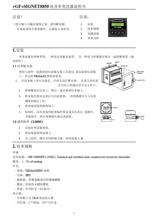
1.安装本变送器有两种类型:一种是仪表板安装型, 另一种是与传感器安装在一起的整体型(通用组件)。
1.1仪表板安装利用与部件一起提供的仪表板安装工具将仪 表安装到仪表板上,并达到NEMA4X 级密封要求。
1.在仪表板上冲出安装孔,并将毛边打磨光滑。
仪表之间在所有方向上的建议净空为1英寸。
2. 将垫圈放在仪表上,然后一起安装到仪表板上。
3. 将安装托架从仪表后方向前滑移, 直到便捷夹卡入仪表侧面的插I 丨内。
4. 将电线连接到接线端上。
5.拆卸时,应在前面用胶带临时固定或从仪表后 部抓牢。
不能放手,然后将便捷夹按出再拆卸。
1.2通用组件(3-8050)1. 安装好变送器基座。
2. 将电线接到变送器上。
3.合上组件,推压并用转锁关紧。
封闭电缆入II 。
2. 技术规格常规适用电极:+GF+SIGNET3-28XX-1 Standard and certified series conductivity/resistivity electrodes 精度:土 2% of reading 外壳:・级别:NEMA4XIP65前板 ・壳体:PBT・观察窗:带聚氨酯涂层的聚碳酸酯 ・键盘:密封的4键硅橡胶 ・重量:约325克(12盎司) 显示器:・字母数子式2X16夜晶显示器 ・对比度:5个级别,用户可任选目录:1. 安装2. 技术规格3. 电路连接4.菜单功能・刷新速度:1秒工作条件工作温度:-19〜70°C (14-158T) 存放温度:-15~80°C ( 5~176°F) 相对温度:0〜95%,不结露 标准与认证• CAS, CE, UL 列入 •通过IS09001认证制造 工作范围传感器输入范闱:• conductance: 0.055 to 400.000|.iS • resistivity: 10KQ to 18.26MQ • TDS: 0.023 to 200.000 ppm• temperature:PT 1000,-25 to 120°C(-13 to 248 F) 电流输出:・4〜20mA,隔离,全量程可调,可反向设定 • 电源:12〜24VDC±5%, regulated. 80niA Max ・ •最人阻抗:12V 时最人50Q,18V 时最人325Q,24V 时最 k 600Q・更新速度:0.5秒•精度:25°C 和 24V 时为土0.03111A 集电极开集模式:高、低、频率、脉冲设定。
+GF+_SIGNET8850电导率变送器手册

+GF+ SIGNET8850-1 电导率/电阻率变送器 警告: z 接入输入输出线前请将电源断开。
z 谨遵说明,以免人身伤害。
1. 安装内置程序式传感器分为两类:面板安装式和就地安装式。
面板式传感器的安装需配备相关的五金器具,本手册包括了面板式安装的完整说明;就地式安装需一整套安装工具包,事实上只要有一套3-8050通用工具包就能够在任何地点安装传感器,该工具包内有就地安装的详细说明。
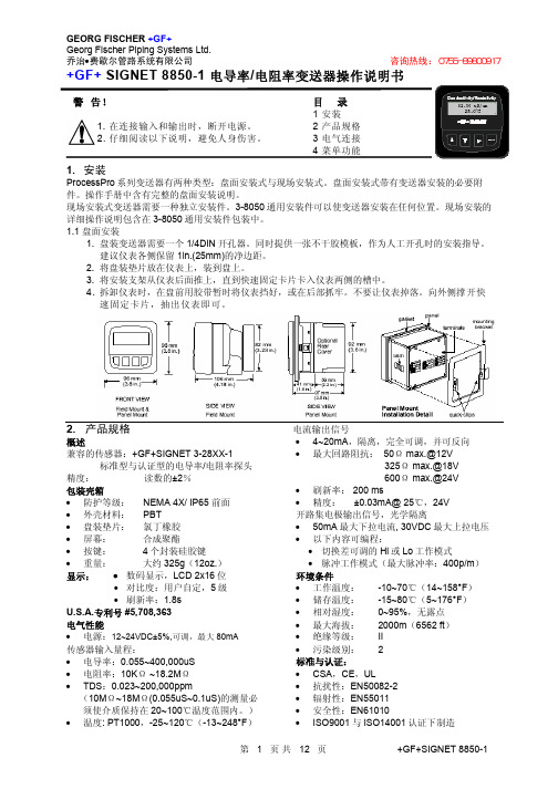
1.1 面板安装1) 面板式传感器的设计装配采用的是1/4 DIN 的打孔机;对于表盘的人工切割,其上粘结的金属板片为安装指南。
各仪表间的推荐间距为1英寸。
2) 装上仪表垫片,安装表盘。
3) 推动仪表后部安装托架,直到卡扣扣上表盘边上的插销。
4) 要取下仪表,或从前面除去临时性保护仪表的胶带,抓紧仪表的后部,不要松手,按下卡扣拔出即可。
前视 侧视(就地安装式&面板安装式)2. 产品说明产品概要:1)兼容电极:+GF+ SIGNET 3-28XX-1标准系列和认证系列电导率/电阻率电极 2)精确度:±2%读数值 3)外设:z 等级:NEMA 4X/IP65正面 z 表壳:PBTz 面板垫片:氯丁橡胶(Neoprene )z 视窗:聚氨酯衬聚碳酸酯 z 键区:4键,硅树脂橡胶 z 重量:约325g (12盎斯) 4)显示:z 字母数字显示式 2X16 LCD z 对比度:用户设置,5级 z 更新速率:1.8s电气参数:z电源:12-24VDC±10%,可调,最大80mA传感器输入范围:z电导率:0.01 — 400000μS/cmz电阻率:10KΩ⋅cm — 100MΩ⋅cmTDS:0.023 — 200000 PPM (可调μS/PPM)z温度:PT 1000,-25 — 120℃(-13 — 248℉);量程超过10MΩ(低于0.1μS)时温度范围必须在20 — 100℃内z被动,独立,完全可调可逆转式4 — 20mA信号能各自输出电导率和温度z最大回路阻抗:最大50Ω @12V最大325Ω @18V最大600Ω @24Vz更新速率:200msz精确度:±0.03mA@25℃,24V开放式收集器输出,独立显示z最大50mA的衰减,最大上升到的电压30VDCz可编程项:z高低可调磁滞z脉冲运行(最大速率:400脉冲/分钟)环境条件:z运行温度:-10 —70℃(14 — 158℉)z存放温度:-15 —80℃(5 — 176℉)z相对湿度:0 — 95%,无冷凝z最大海拔:2000m(6562英尺)z绝缘类别:IIz污染等级:2标准和认证:z CSA,CE,ULz免疫性:EN50082-2z放射性:EN55011,Class-Bz在ISO9001和ISO14001标准下生产制造U.S.A.专利号 #57083633. 电气接线 警告:卸线前没有完全开启终端接线夹可能会永久性损坏设备。
GF_SIGNET_8550流量变送器操作说明书

+GF+ SIGNET 8550-1 流量变送器操作说明书注意:1 在连接输入和输出时,断开电源;2 细阅读以下说明,避免人身伤害。
目录1 安装2 性能指标3 电气接线4 菜单功能1 性能指标尺寸正视(盘装和现场安装) 侧视(现场安装) 侧视(现场安装8050) 侧视(现场安装8051)普通·适配型号:+GF+ SIGNET 流量传感器密封:·等级:NEMA 4X/IP65·外壳:PBT·盘装垫片:氯丁橡胶·屏幕:合成聚酯·按键:4个硅胶按键·重量:约325克显示:·2×16数字LCD·刷新速度:1秒·对比度:5个等级,可选择·显示精度:25ºC时读数的±0.5%·热敏偏移量:读数的±0.005%/ºC电气·电源:12-24VDC±10%,最大电流61mA 传感器输入:·范围:0.5-1500Hz·传感器电源:2线:1.5mA@5VDC±10%3或4线:20mA@5VDC±10%·光电隔离·短路保护电流输出:·4-20mA,隔离,可调整且反向·最大回路阻抗:50Ω@12V,325Ω@18V,600Ω@24V·刷新速度:100ms·输出精度:±0.03mA集电极开路输出,光电隔离:·50mA最大下拉电流,30VDC最大上拉电压·可编程,对于·高,低,可调延时·脉冲(最大:300个脉冲/分钟)环境·运行温度:-10ºC-70ºC (14-158ºF) ·保存温度:-15ºC-80ºC (5-176ºF) ·相对湿度:0-95%,无露点·最大海拔:2000m(6562ft)·绝缘等级:Ⅱ·污染等级:2标准和认证·CSA,CE,UL·抗干扰性:EN50082-2·辐射:EN55011·安全:EN61010·ISO9001和ISO14001认证下制造2 安装ProcessPro 变送器有两种安装方式:盘装和现场安装。
GF SIGNET 8850-1 电导率电阻率变送器操作说明书
第 5 页 共 12 页
+GF+SIGNET 8850-1
GEORG FISCHER +GF+ Georg Fischer Piping Systems Ltd. 乔治•费歇尔管路系统有限公司
端子 1-2:辅助电源 为测量电路提供 DC 电源 8850 系统都需要辅助电源
端子 5-6:开路集电极输出信号 • 晶体三极管输出,可编程设置以下内容(见 CALIBRATE
标定菜单): 切换差可调的 High 或 Low 设定值与比例脉冲信号(最大 值为 400p/m) • 不用时可以隐藏(Off 状态)
第 5、6 步注意事项: • 在编辑期间,所有输出功能都是有效的 • 只有正在闪动的位可被编辑 • 按右向键可以使闪动位循环移动 • 在按下 ENTER 键后,编辑好的值立即有效 • 如果在 10 分钟内没有按任何键,变送器会保存最后的修
改值,并返回到第 3 步 • 第 6 步(按下 ENTER 键)操作也会返回到第 3 步 • 重复第 3~6 步操作,所有的编辑即可完成
两块变送器与 PLC/记录仪连接,单独供电
8850 系统都需要辅助电源。
3.2 传感器输入连接
接线提示 • 不要将传感器的电缆与 AC 电缆敷设在同一根电缆导管内。电子噪音会干扰传感器信号。 • 将电缆敷设在接地的金属电缆管中有助于防止电子噪音与机械损伤。 • 将电缆入口处密封,以防潮汽的侵害。 • 每个端子只能插入一根导线。如果两根导线接入同一端子,要在外部连好。
GEORG FISCHER +GF+ Georg Fischer Piping Systems Ltd. 乔治•费歇尔管路系统有限公司 咨询热线:0755-89800917
GFSIGNET8850-1电导型变送器说明书讲解
+GF+SIGNET 8850-1 电导型变送器说明书注意目录● 在输入输出接 1. 安装线前切断电源。
2. 技术性能● 认真地根据指 3. 电路连接导以避免个人伤害。
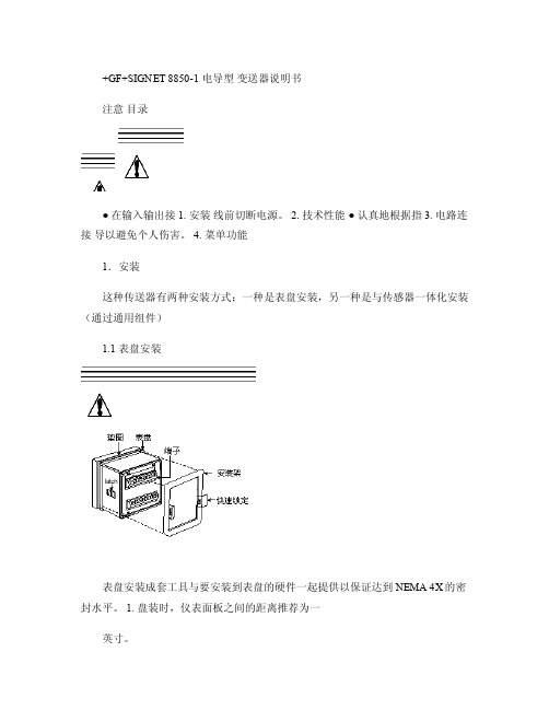
4. 菜单功能1.安装这种传送器有两种安装方式:一种是表盘安装,另一种是与传感器一体化安装(通过通用组件)1.1 表盘安装表盘安装成套工具与要安装到表盘的硬件一起提供以保证达到NEMA 4X的密封水平。
1. 盘装时,仪表面板之间的距离推荐为一英寸。
2. 将垫片装在仪表上,然后装盘。
3. 安装架从仪表背部装入,滑动到锁定位置。
4. 接线到端子。
5. 需要取下仪表时,用带子从前面固定仪表或从背部用手抓住仪表。
不要放开。
压下快速锁定装置,取出仪表。
1. 2通用组件(3-8050)1.安装变送器板。
2.接线到端子。
3.用压旋装置固定,密封出线口。
2.技术指标概述兼容电极:+GF+SIGNET 3-28XX-1 标准系列电导精确度:±2% 读取误差外壳:● 防护等级:NEMA 4X/IP65 ● 壳体材料:PBT● 显示窗:聚氨酯● 键盘:密封4键硅橡胶● 重量:325克显示:● 2*16LCD● 对比度:用户可选择,5级● 刷新周期:1秒环境环境温度:-10到70C(14到158F 存储温度:-15到8OC(5到176F 相对湿度:0到95%,无浓缩标准● CSA,CE,UL● ISO9001标准下制造美国专利号#5,708,363 电气特性传感器输入范围:● 传导率:0。
055到400,000微秒● 阻抗:10-18.26千欧● TDS :0.023-2000,000PPM电气特性传感器输入范围:● 传导率:0。
055到400,000微秒● 阻抗:10-18.26千欧● TDS :0.023-2000,000PPM ● 温度:PT1000, -25到120C (-13-248F )电流输出:● 4到20mA 隔离,完全可调和可逆输出● 电源:12到24VDC ±5% 稳压● 最大闭环阻抗:50欧姆 MAX @12V, 325欧姆 MAX @18V, 600欧姆MAX @ 24V ● 刷新周期:0.5秒● 精确度:±0.03mA@ 25C,24V集电极开路输出:高,低,可编程脉冲● 集电极,隔离,50mA 吸入或源电流,30VDC max拉入电压● 滞后:用户可调3.电气连接注意:在拆除电线前没有完全打开端子接线夹可能导致仪表的永久损坏。
8850电导变送器
+GF+SIGNET8850ProcessProProcessPro™™电导/电阻变送器描述+GF+SIGNET8850电导/电阻变送器应用广泛并且便于安装和使用。
可用于电导、电阻或TDS信号传输和显示。
多种安装形式适用于各种实际使用。
由于取消了电位计、跳线和DIP 开关,全部微处理器处理保证更广的运行范围和长期信号稳定性。
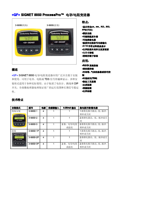
技术特点安装型式型号电源传感器输入4-20mA输出集电极开路/继电器现场安装3-8850-14111路集电极开路高、低、脉冲、频率或关闭3-8850-24112路继电器高、低、脉冲或关闭3-8850-3412路,电导/电阻或温度2路集电极开路高、低、脉冲、频率或关闭盘装3-8850-1P4111路集电极开路高、低、脉冲、频率或关闭3-8850-2P4112路继电器高、低、脉冲或关闭3-8850-3P412路,电导/电阻或温度2路集电极开路高、低、脉冲、频率或关闭3-8850(现场)3-8850(盘装)尺寸盘装现场安装安装变送器可以盘装或现场安装。
选择通用安装组件(3-8050)将变送器安装在传感器附近的位置上。
1盘装2通用安装所有盘装变送器(3-8850-XP)包括一个支架和垫圈,满足NEMA4X防水等级。
盘装变送器需要标准的1/4DIN盘面开孔。
通用安装组件(3-8050)可以单独定货,它包括一个导线基座,锁定环和将变送器安装在管道、墙壁上或其他固定设备表面上的适配器。
电导/电阻变送器3-8850-XP包括支架和垫圈电导/电阻传感器通用适配器3-8050包括锁定环导线基座通用适配器(固定于管道、墙壁)电导/电阻传感器3-8050组件背后端子视图技术参数普通指标适用电极:+GF+SIGNET3-28XX-X标准和NIST 认证的电导和电阻电极精度:读数的±2%密封:·等级:前面板NEMA4X/IP65·外壳:PBT·盘装垫圈:氯丁橡胶·屏幕:合成聚酯·按键:4个硅胶按键·重量:约325克显示:·2×16数字LCD·对比度:5个等级,可选择环境运行温度:-10ºC-70ºC(14-158ºF)保存温度:-15ºC-80ºC(5-176ºF)相对湿度:0-95%,无露点标准和认证·CSA,CE,UL·ISO9001认证电气电源:·12-24VDC±10%,可调整,(-1)最大21mA,(-2)最大220mA,(-3)最大60mA传感器输入范围:·电导:0.055-400000μs·电阻:10KΩ-18.2MΩ·TDS:0.023-200000ppm·温度:PT1000,-25-120ºC(-13-248ºF)电流输出:·4-20mA,隔离,可调整且可反向·最大回路阻抗:50Ω@12V,325Ω@18V,600Ω@24V·刷新速度:0.5s·精度:±0.03mA@25ºC,24V继电器输出:·机械SPDT接点:高、低、脉冲、关闭·最大额定电压:5A@30VDC,5A@250VAC阻性负载·滞后量:可调整·最大400脉冲/分钟集电极开路输出:高、低、脉冲、关闭·集电极开路,光电隔离,50mA最大下拉电流,30VDC最大上拉电压·最大400脉冲/分钟3.端子8850-2订货资料型号编码描述3-8850-1159000228电导/电阻变送器,现场安装3-8850-1P159000229电导/电阻变送器,盘装3-8850-2159000230电导/电阻变送器,现场安装,继电器输出3-8850-2P159000231电导/电阻变送器,盘装,继电器输出3-8850-3159000232电导/电阻变送器,现场安装,单路输入/双路输出3-8850-3P159000233电导/电阻变送器,盘装,单路输入/双路输出附件型号编码描述3-8050159000184通用安装组件3-8050.395159000186变送器NEMA4X密封盖3-80521590001883/4”整体安装件3-8050.396159000617RC滤波器组件(用于继电器输出)3-0000.596159000641牢固的墙装支架3-8050.392159000640200型新式适配器工程规格书:·变送器应该符合CE、CSA&UL标准。
SIGNET 8850-1 电导率 电阻率 变送器 操作说明书
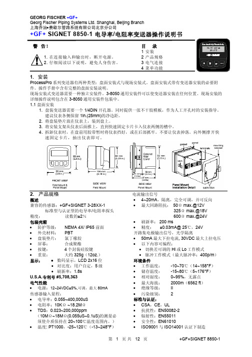
• 保持 2 秒钟可进入标定菜单(CALIBRATE)
• 保持 5 秒钟可进入选项菜单(OPTIONS)
第 2 步:密码为顺序按上-上-上-下方向键
• 输入密码后,将显示所选菜单的第一项内容
第 3 步:用上或下方向键翻动菜单
第 4 步:用右向键选中要进行编辑的菜单项
• 显示内容的第一位开始闪动
第 5 步:按上或下方向键对闪动位进行编辑
改值,并返回到第 3 步 • 第 6 步(按下 ENTER 键)操作也会返回到第 3 步 • 重复第 3~6 步操作,所有的编辑即可完成
第 5 步:设置有误吗? 在有闪动位的情况下,同时按上、下方向键。 将取消被编辑项的最后的设置内容,并返回 到第 3 步。
第 5 页 共 12 页
+GF+SIGNET 8850-1
接线端子
第 3 页 共 12 页
+GF+SIGNET 28XX-1 标准型与认证型探头
+GF+SIGNET 8850-1
GEORG FISCHER +GF+ Georg Fischer Piping Systems Ltd. Shanghai, Beijing Branch 上海乔治•费歇尔管路系统有限公司北京分公司
• 按右向键前移闪动位的位置
第 6 步:按 ENTER 键保存新的设置内容并返回到第 3 步
第 1 步注意事项:
第 2 步注意事项:
• 正常显示为视图菜单(View )状态
当显示“Enter Key Code”时,如果在 5 分钟
• 进入标定菜单(CALIBRATE)与选项菜单
内没按任何键,显示会返回到视图菜单
Standard
GF+ SIGNET 3-8800 电导率传输器说明书
+GF+ SIGNET 3-8800 Conductivity TransmitterInstruction ManualGEORGE FISCHER +GF+SAFETY INSTRUCTIONS1.Do not remove from pressurized lines.2.Do not exceed maximum temperature/pressurespecifications.3.Do not install/service without followinginstallation instructions (see sensor manual). 4.Wear safety goggles and faceshield duringinstallation/service.5.Do not alter product construction.6.Failure to follow safety instructions could resultin severe personal injury!Chapter Page 1Introduction1 1.1Description12Calibration3 2.1Wet Calibration3 2.2Calibration Procedure4 2.3Installing Optional Display Board5 2.4Display Board Range Adjustment63Installation7 3.1General7 3.2Positioning7 3.3In-Line Installations8 3.4In-line Fitting Options8 3.5Submersible Installations10 3.6Electrical Installation11 4Conductivity Sensor Maintenance13 4.1Maintenance Tips13 4.2Replacement Parts14 4.3Troubleshooting Guide15 Specifications16Dimensional View17Warranty18Table of ContentsUnpacking and InspectionThe following items are included in your Conductivity transmitter package:• 8800 Conductivity Transmitter 3-8800.103-XX • Instruction manual 3-8800.090Please fill out and return the warranty card as soon as possible.Warranty recordFor your protection, record the purchase informa-tion for future reference. The serial number decal is located within the enclosureModel: +GF + SIGNET 8800 Conductivity TransmitterPurchase date:__________________________Serial number:__________________________Purchased from:_________________________Purchase order number:___________________-XX Refers to electronic range options:-1P= 0 to 20 µS, 0.5 cell -2P= 0 to 200 µS, 0.5 cell -3P= 0 to 2,000 µS, 2.0 cell -4P= 0 to 10,000 µS, 2.0 cellChapter 1IntroductionThis manual contains description, instructions and specifications for the installation, calibration and care of the +GF + SIGNET 8800 Conductivity Transmitter. Should you require further assistance,please contact your +GF + SIGNET dealer.1.1 DescriptionThe +GF + SIGNET 8800 Conductivity system is used in conjunction with an insertion type sensor that continuously measures the conductivity (total dissolved solids or gases) of a solution in a wide variety of process applications.The Conductivity Transmitter consists of aconductivity sensor and an electronics package (transmitter). The electronics package is housed in a NEMA 4X/IP65 enclosure.The +GF + SIGNET 8800 transmitter system can be converted for submersible applications such as water wells, tanks etc. Optional submersion kit,p/n 3-2700.391 includes the necessary parts and assembly instructions for extending the sensor length up to 12 ft. The submersible kit requires a 3/4 inch pipe with male NPT threads on both ends, (user supplied) that is used to physically extend the sensors' length.1The submersion kit also requires an extended cable, (purchased separately) which is used to interface the sensor to the electronics. Optional extension cable p/n 3-8800.261-XX (-03, -06, -09 or -12 ft.). Refer to Figure 1 below:2Figure 1 Transmitter submersion kit and required extension cable.Chapter 2Calibration2.1 Wet CalibrationYour 8800 Conductivity transmitter has been electronically calibrated at the factory before shipment. You will need to perform a wetcalibration to compensate for electrode variations.Wet calibration compares the output of thetransmitter against the conductivity value of a test solution.Wet Calibration should be performed while the 8800 Conductivity transmitter is beingpermanently installed. When done carefully, you can trim the transmitter accuracy to within ±1% of full scale.3Figure 2Adjustment pots and connectorsEquipment Required• Small screwdriver• Power supply (10 to 30 VDC)• Ammeter2.2 Calibration Procedure1.Connect power supply to transmitter input placing an ammeter in series with the input power, see Figure 3.4Figure 3Transmitter Hook-up2.With the Conductivity electrode in the air (0 conductance) adjust the Zero pot (R26) for 4.00 mA.3.Place the electrode into a solution of known conductance and adjust the Span pot (R17) for the corresponding mA value.4.Remove the sensor from solution and verify that the sensor reads 4.00 mA.5.Repeat steps 2 through 4 as necessary.mA =[(Known Cond./Full Scale Cond.) • 16 mA] + 4 mA NOTE:The current output can be monitored in several ways (see Figure 8)5Figure 4Display BoardInstallation Drawing part no. 3-8000.3902.3 Installing Optional Display BoardThe addition of the display board option (p/n 3-8000.390) to the conductivity transmitter is done in the following manner.1. Remove snap-on cover allowing access to the P4 connector.2. Plug the four conductor ribbon cable into the P4 connector, see Figure 4.3. If necessary use a small blade (e.g Exacto knife)to remove any conformal coating from the standoff holes or calibration pot access holes.4. Carefully snap the display board onto the three standoffs.5. Re-calibrate the instrument as explained in section 2.2.62.4 Display Board Range AdjustmentThe display board displays from zero to one hundred percent of range. This PCB has aone-point calibration which may need to be done at installation.1. Re-calibrate per section2.22. Calculate percentage of full scale and adjust Range pot on display board so that the display shows the proper percent of Full Scale.Model no. Full Range 3-8800.103-1P 20 µS 3-8800.103-2P 200 µS 3-8800.103-3P 2,000 µS 3-8800.103-4P 10,000 µSZERO SPANInterface cableconnection to main PC board. Located on underside of LCD boardRange Potentiometer;Located on underside of LCD board. Can be adjusted through the hole in the electronics housing.Figure 5Range Potentiometer LocationT he display board drawsapprox. 200 µA of current.When added, the transmitter requires recalibration.(Solution value ÷ Full Range) • 100 = Percentage3.1 GeneralThis transmitter may be installed in harshenvironmental locations. However, when possible the transmitter should be located so as to minimize the effects of temperature gradients and to avoid vibration and shock.3.2 PositioningIn order to achieve good repeatable results care must be taken in the placement of the sensor. It is important that the sensor electrodes are fully immersed in the process fluid. Flow rates around the sensor must be limited so as not to produce air pockets which will affect the signal path through the fluid. We recommend that you do not mount completely upside-down as sediments may become trapped in the sensor and that you do not mount at the very top of the pipe because the pipe might not always be full.7The information provided on sensor positioning are recommendations only. The primary consideration is that the electrodes are in full contact with the process fluid.If sediments are present we recommend avoiding the 6O'clock position. Figure 6I n-line Sensor Positioning DiagramChapter 3Installation3.3 In-Line InstallationsThe 8800 Conductivity transmitter sensor system is designed for installation into a pipe using standard +GF + SIGNET fittings, (up to 4 inch) or the optional +GF + SIGNET pipe adaptor fitting (p/n P31515-0V200). Refer to section 3.4 for additional information.3.4 In-line Fitting Options These fittings provide the proper installation parameters that are critical to the calibration of the conductivity system.Fitting Installation/Plastic Fittings Tees:•All tee fittings sold by +GF + SIGNET are "glue-on" type except for the PVDF tees which are thermally fused. Be aware that PVC and CPVC tees require different types of primer and cement.•Tee fittings are available for pipes from 0.5 to 4 inches in diameter.Saddles:•Plastic "glue-on" saddles are available for lines from 2 to 4 inches in diameter.•2 to 4 inch "glue-on" saddles require a 1-7/16inch hole in the pipe. (O-ring not used with glue-on type)•The hole must be completely deburred to be free of any projections.•When assembling plastic saddles, the arrows on the wedges must match the direction of the arrows on the pipe saddle.Misc:+GF + SIGNET also offers a pipe adaptor specifically designed for installing +GF + SIGNET analytical sensors into in-line applications8Caution: Wheninstalling saddlefittings, depressur-ize and drain pipebefore drilling fitting hole.+GF + SIGNETplastic "glue-on" Tee Fitting+GF + SIGNET Plastic"glue-on" Saddle Fitting(p/n P31515-0V200). This pipe adaptor can be installed in any standard 1-1/4 inch FNPT pipe fitting.Fitting Installation/Metal FittingsWelded fittings MUST be installed by a certified welder.The plastic sensor insert in the Weldolet fitting MUST be removed during the welding process.When reinstalled, it is important that the insert be threaded to the proper height "H" dimension to ensure full insertion of the sensor electrodes,see page 10.• 2 to 4 inch Weldolet fittings require a 1-7/16inch hole in the pipe.•The hole must be completely deburred to be free of any projections before installing the Weldolet fitting.Pipe Tees: Metal Pipe Tees are available for 0.5to 2 inch metal pipes. Materials include iron,carbon steel, stainless steel, and copper or bronze. All tees are threaded with NPT threads except for copper and bronze tees, which have solder or braze type fittings.•Use thread sealant compound on fittings with threaded connections.9+GF + SIGNET "weld-on"Weldolet Fitting +GF + SIGNET Metal Pipe Tee Fitting+GF+ SIGNET Weldolet Fitting103.5 Submersible InstallationsThe 8800 Conductivity transmitter sensor system can be made submersible through the use of the submersible kit p/n 3-2700.391 and extension cable, p/n 3-8800.261-XX (-XX designates overall cable length from -01 to -12 ft., see Figure 1.3.6 Electrical InstallationThe transmitter has a 1/2 inch conduit opening for power/signal wiring, see Figure 7.The sensor input connection is located on the lower PCB (below optional Display PCB). To access the connector, remove the housing cover followed by the electronics cover (snap on/off).The connector is now accessible between theFigure 78800 ConductivityTransmitter In-lineInstallation11Signal wiring should not run in conduitor in open trays with HVAC wiring and should not be run near heavy electrical equipment. Leads should be color coded for polarity identification.The conduit connection on the transmitter housing should be sealed or plugged to avoid accumula-tion of moisture in the housing. If the conduit is not sealed, the transmitter should be mounted with the opening downward for draining.Signal wiring may be ungrounded or grounded at any place in the signal loop. Power supply regula-tion is not critical. Make sure that the power supply source conforms to the requirements of thetransmitter and that the current rating of the supply is not exceeded, particularly if more than one transmitter is connected to the supply in parallel.NOTE:This transmitter is designed to eliminate ground loops and other electrical interactions between system components even if several transmitters are powered by a common supply in parallel.Make sure that electrical characteristics of the remote output device are compatible with the transmitter output: Total load resistance must not exceed 700 ohms using a 24 VDC power supply. Total load resistance is the sum of the individual resistances of all devices which are connected in series with the signal output lead.Equation:RL = V S -10/0.02where R L = Load Resistance in ohms V S = Supply Voltage 10 = Minimum operating voltage0.02 = 20 mA (maximum current)1213Chapter 4Conductivity Sensor Maintenance 4.1 Maintenance TipsThe electrodes contact the solution and transfer a signal through the solution being measured. It is recommended that the electrodes maintain contact with fluid. If allowed to air dry, precipitates may form on the electrodes causing higher than normal readings and possibly contaminating the process fluid. If precipitates form, the electrodes may be cleaned by immersing the sensor in warm water and scrubbing the electrodes with a soft nylon brush.It is important that the sensor is not exposed to oils which may coat the electrodes. This may seriously affect the readings.In extreme cases it may be necessary to clean the sensor with alcohol to remove oils. Werecommend using a cotton swab and brushing the electrode clean instead of dipping the entire sensor body in acetone.In submersible applications the sensor should be located fully immersed and away from the presence of any bubbles.In some instances it may be necessary to devise a periodic maintenance schedule to clean the electrodes and verify calibration.4.2 Replacement Parts144.3 Troubleshooting Guide Problem Action Cause• Gain pot set too high • Incorrect operating range • Excessive Quiescent current •Application range exceeds the electronics range.•Unit is not properly calibrated•Range pot misadjusted• Check unit model number, see Unpacking and Inspection section (opposite page #1) • Re-calibrate, see page 4 • Re-calibrate display, see page 5•Application range belowthe electronics range • Sensor not connected Display/outputreads off scale •Check unit model number, see Unpacking and Inspection section (opposite page #1)•Check sensor connection Display/outputreads zero(4 mA)• System power or ground OPEN • Check system wiringDisplay is blank/no current • Reduce Gain/Span potadjust• Check unit model number, see Unpacking andInspection section (opposite page #1)• Send for repairTransmitter cannot be calibrated (insufficient Zero adjust)• Incorrect operating range • Unit not calibrated • Output transistor damaged • Check unit model number, see Unpacking andInspection section (opposite page #1)• Re-calibrate, see page 4• Send for repair• Air bubbles contacting sensor • Coated electrodes • Leaking submersion kit• Check installation• Clean sensor, see page 11• Clean/replace cableinstall new seal Transmitter output changes erratically Transmitter cannot be calibrated (insufficient Gain adjust)15Specifications Optional Display:0 - 100%, 2-1/2 digit LCD(factory installation recommended),#3-8020.390Loop power:10 to 30 VDCLoop impedance:•1Ω @ 10 VDC•100Ω @ 12 VDC•1000Ω @ 30 VDCElectronics operating temp:•-15 to 50 °C (5 to 122 °F)Max sensor pressure/temperature:•7 bar @ 20 °C (100 psi @ 68 °F)• 1.7 bar @ 90 °C (25 psi @ 194 °F)Operating ranges:•-1P0 to 20 µS0.05 cell•-2P0 to 200 µS0.05 cell•-3P0 to 2,000 µS 2.0 cell•-4P0 to 10,000 µS 2.0 cellCurrent output:2-wire, 4 to 20 mA signalAccuracy:±1% of rangeRelative Humidity:0 to 95%, non-condensingEnclosure materials:•Electronics enclosure:Glass-filled PP, NEMA 4X/IP65•Enclosure seal:Viton®•Window:PolycarbonateWetted sensor materials:•Sensor body:Glass-filled PP•Electrodes:Titanium•Sensor o-rings (2):Viton®•Optional o-rings:EPR, #1224-0021Kalrez, #1228-0021Immunity:EN50082-1Emissions:EN55011Agency Approvals:CE16Figure 98800 Conductivity TransmitterDimensional Views 2.0 Cell Constant -3 (0 to 2,000 µS)-4 (0 to 10,000 µS)0.05 Cell Constant -1 (0 to 20 µS) -2 (0 to 200 µS)17Warranty Limited Two-Year WarrantySignet Scientific Company warrants its instrumentsto be free from defects in material and workman-ship under normal use for a period of two yearsfrom the date of purchase by the initial owner, orthree years from date of manufacture, whichevercomes first, as described in the followingparagraphs.This warranty does not cover defects caused byabuse or electrical damage. Signet ScientificCompany will not cover under warranty anyinstruments damaged during shipment to thefactory less case or if improperly packed. Repairattempts by anyone other than authorized servicepersonnel will void the warranty. Proof of date ofpurchase will be required before warranty repairscan begin. Transducers and cables will not becovered after installation.Parts which prove to be defective in the first yearwill be repaired or replaced free of chargeincluding labor, shipped F.O.B. our factory or adesignated service center (addresses furnishedupon request).Only non-moving parts, such as electricalcomponents, which prove defective during thesecond year are warranted. Meter movements willnot be covered. All units qualifying for warrantyservice after one year are subject to a servicecharge for replacement of non-moving parts.Items returned for warranty repair must be shippedprepaid and insured. Warranty claims areprocessed on the condition that prompt notificationof a defect is given to Signet Scientific Companywithin the warranty period.18Signet Scientific Company shall have the sole rightto determine whether in fact a warranty situationexists.Signet Scientific Company is continually makingdesign changes and improvements that adapt tothe original circuit configuration. These will beincorporated as required in older units on aminimal charge basis while under warranty.Consequential DamagesSignet Scientific Company shall not be liable forspecial consequential damages of any nature withrespect to any merchandise or service sold,rendered or delivered.This warranty gives you specific legal rights andyou may also have other rights which vary fromstate to state.19+GF + SIGNETSales Offices:USAGeorge Fischer, Inc., 2882 Dow Avenue, Tustin, CA 92780/USA,Tel. (714) 731-8800, Fax (714) 731-6201SwitzerlandGeorg Fischer Rohrleitungssysteme AG, P.O. Box 671, CH-8201 Schaffhausen/Switzerland,Tel. 052/631 1111, Fax 052/631 2830SingaporeGeorge Fischer Pte. Ltd., 15 Kaki Bukit Road 2, KB Warehouse Complex, Singapore 1441,Tel. 65/747 0611, Fax 65/747 0577JapanKubota George Fischer, 2-47 Shikitsuhigashi, 1-Chome, Naniwa-Ku, Osaka, 556-91 Japan,Tel. 816/648 2545, Fax 816/648 2565ChinaGeorg Fischer Ltd., Rm 1503, Business Residence Bldg. of Asia Plaza,2-3 Bldg. No. 5th Qu Anzhenxili, Chaoyang Qu, Beijing 100029, P.R. China,Tel. 86/10 6443 0577, Fax 86/10 6443 0578Australia George Fischer Pty. Ltd., Suite 3, 41 Stamford Road, Oakleigh, Victoria 3166, Australia,Tel. 61/3 9568 0966, Fax 61/3 9568 0988Signet Scientific Company, 3401 Aerojet Avenue, El Monte, CA 91731-2882 U.S.A.,Tel. (626) 571-2770, Fax (626) 573-2057GEORGE FISCHER +GF + Piping Systems© Signet Scientific Company 1992 Printed in U.S.A.PRINTED ON RECYCLED PAPER 3-8800.090B-11/97。
Signet 8550-2流量变送器使用指南说明书

Signet 8550-2 Flow Transmitter2. InstallationProcessPro transmitters are available in two styles: panel mount and fi eld mount. The panel mount is supplied with the necessary hardware to install the transmitter. This manual includes complete panel mounting instructions.Field mounting requires one of two separate mounting kits. The 3-8051 integral kit joins the sensor and instrument together into a single package. The 3-8050 Universal kit enables the transmitter to be installed virtually anywhere.Detailed instructions for integral mounting or other fi eld installation options are included with the 3-8051 Integral kit or the 3-8050 Universal kit.3-8550.090-2 J 9/05 English*3-8550.090-2*English2Signet 8550-2 Flow TransmitterSystem Pwr Loop -System Pwr Loop +AUX Power - AUX Power +4321Sensr Gnd (SHIELD)Sensr IN (RED)Sensr V+(BLACK)131211Relay 2(NO)Relay 2(COM)Relay 2(NC)Relay 1(NO)Relay 1(COM)Relay 1(NC)10987653. Electrical ConnectionsCaution: Failure to fully open terminal jaws before removing wire may permanently damage instrument.Wiring Procedure1. Remove 0.5 - 0.625 in. (13-16 mm) of insulation from wire end.2. Press the orange terminal lever downward with a small screwdriver to open terminal jaws.3. Insert exposed (non-insulated) wire end in terminal hole until it bottoms out.4. Release orange terminal lever to secure wire in place. Gently pull on each wire to ensure a good connection.Wiring Removal Procedure1. Press the orange terminal lever downward with a small screwdriver to open terminal jaws.2. When fully open, remove wire from terminal.Terminals 5-10: Relay OutputsTwo sets mechanical SPDT contacts, programmable (see CALIBRATE menu) as:• High or Low setpoint with adjustable hysteresis • Volumetric pulse based on totalizer • May be disabled (Off) if not used.Terminals 3 and 4: Loop Power 12-24 VDC ±10% system powerand current loop output.Max. loop impedance: 50 Ω max. @ 12 V 325 Ω max. @ 18 V 600 Ω max. @ 24 VTerminals 11-13: Flow sensor inputTerminals 1 and 2: AUXILIARY power Provides power for relay operation and for fl ow sensors requiring more than 1.5 mA current.clearance on all sides between instruments is 1 inch.2. Place gasket on instrument, and install in panel.3. Slide mounting bracket over back of instrument until quick-clips snap into latches on side of instrument.4. To remove, secure instrument temporarily with tape from frontor grip from rear of instrument. DO NOT RELEASE.Press quick-clips outward and remove.3Signet 8550-2 Flow Transmitter 3.1 System Power/Loop Connections3.2 Sensor Input ConnectionsWiring Tips:• Do not route sensor cable in conduit containing AC power wiring.Electrical noise may interfere with sensor signal.• Routing sensor cable in grounded metal conduit will help preventelectrical noise and mechanical damage.• Seal cable entry points to prevent moisture damage.• Only one wire should be inserted into a terminal. Splice double wiresoutside the terminal.Maximum cable length is 200 ft. for 515/8510-XX, 525 , 2517 and any sinusoidal fl ow signal.Maximum cable length is 1000 ft. for 2536/8512-XX, 2540/2541, vortex, and any open-collector fl ow signal.TerminalsSensr Gnd (SHIELD)Sensr IN (RED)Sensr V+(BLACK)131211All Flow sensorsStand-alone application, no current loop usedTransmitter• AUXILIARY Power is required for all systems where relays are used.4Signet 8550-2 Flow TransmitterHysteresisLow SetpointRelay energized Relay relaxedHigh SetpointVIEW menu• During normal operation, the ProcessPro displays the VIEW menu.• When using the CALIBRATE or OPTIONS menus, the ProcessPro will return to the VIEW menu if no activityoccurs for 10 minutes.• To select the item you want displayed, press the UP or DOWN arrow keys. The items will scroll in acontinuous loop. Changing the display selection does not interrupt system operations.• No key code is necessary to change display selection.• Output settings cannot be edited from the VIEW menu.3.3 Relay outputThe relay outputs can be programmed to respond when the fl ow rate moves above or below a setpoint, or it can be used to gener-ate a pulse that is relative to the fl ow volume. The relays can be disabled if not in use.• LowRelay triggers when the fl ow rate is less than the setpoint.The relay will relax when the fl ow rate moves above the setpoint plus the hysteresis value.• HighRelay triggers when the fl ow rate is greater than the setpoint.The relay will relax when the fl ow rate drops below the setpoint plus the hysteresis value.• PulseRelay output is a pulse based on the volume of fl uid that passes the sensor. Set any value from 0.0001 to 99999.Monitor the Permanent Totalizer value.Monitor the 4-20 mA Loop output.Monitor date for scheduled maintenance or date of last calibration.(See description in Calibration Menu.)View MenuDisplayDescription0.0 GPMTotal: 12345678 >Perm: 12345678 GallonsLoop Output: 12.00 mA Last CAL:04-20-06Monitor the fl ow rate and the resettable totalizer. Press the RIGHT ARROW key to reset the totalizer. If the Reset is locked, you will need to enter the Key Code fi rst. Lock or Unlock the totalizer in the OPTIONS menu. This is the permanent View display.All of the displays below are temporary. After ten minutes the display will return to the permanent display.5Signet 8550-2 Flow Transmitter Notes on Steps 5 and 6:• All output functions remain active during editing.• Only the fl ashing element can be edited.• RIGHT ARROW key advances the fl ashing element in a continuous loop.• Edited value is effective immediately after pressing ENTER key.• Step 6 (pressing ENTER key) always returns you to Step 3.• Repeat steps 3-6 until all editing is completed.ProcessPro Editing Procedure:Step 1. Press and hold ENTER key:• 2 seconds to select the CALIBRATE menu • 5 seconds to select the OPTIONS menu.Step 2. The Key Code is UP-UP-UP-DOWN keys in sequence.• After entering the Key Code, the display will show the fi rst item in the selected menu.Step 3. Scroll menu with UP or DOWN arrow keys.Step 4. Press RIGHT ARROW key to select menu item to be edited.• The fi rst display element will begin fl ashing.Step 5. Press UP or DOWN keys to edit the fl ashing element.• RIGHT ARROW key advances the fl ashing element.6Signet 8550-2 Flow TransmitterAll Relay settings repeat for Relay 2.Calibrate MenuDisplay(Factory settings shown)DescriptionFlow Units:GPM >Flow K-Factor:60.000> Total Units:Gallons> Total K-Factor60.000>Loop Range: GPM 0.000 → 100.0> Relay1 Mode:Low > Relay1 Setpnt:10.000 GPM> Relay1 Hys:5.0000 GPM> Relay1 Volume:100.00 Gallons> Relay1 PlsWdth:0.1 Seconds> Last CAL:04-20-06The fi rst three characters set the Flow Rate units of measure. They have no effect on calculations. They may be any alpha or numeric character, upper or lower case.The last character sets the Flow rate Timebase. Select S (seconds), M (minutes), H (hours) or D (days).This setting tells the transmitter how to convert the input frequency from the fl ow sensor into a fl ow rate. The K-factor is unique to the sensor model and to the pipe size and schedule. Refer to data in the sensor manual for the correct value. Limits: 0.0001 to 99999. (The K-factor cannot be set to 0.)This setting identifi es the Totalizer units. It has no effect on any calculation. It serves as a label only. Each character can be any alpha or numeric selection, upper or lower case.This setting tells the transmitter how to convert the input frequency from the fl ow sensor into a volumetric total. It also is used as the basis for the volumetric Pulse mode.The setting is usually the same as the Flow K-factor, or different by x10 or x100. Limits: 0.0001 to 99999. (The K-factor cannot be set to 0.)Select the minimum and maximum values for the 4-20 mA Current loop output. The 8550 will allow any values from 0.0000 to 99999. Select the desired mode of operation for relay 1. Options available are High, Low or volumetric Pulse. The signal may be disabled if not in use. In Low or High Mode, the relay output will be activated when the Flow rate reaches this value. Be sure to modify this setting if you change the Flow Units. Relay 1 will be deactivated at Setpoint ± Hysteresis, depending on High or Low Setpoint selection. (See details on page 4.) In Pulse mode, the relay output will generate one pulse when this volume of fl ow passes the sensor. (The measurement is based on the Total K-factor.) The 8550 will allow any value from 0.0001 to 99999.In Pulse mode, this setting defi nes the duration of the relay pulse. The 8550 allows any value from 0.1 seconds to 999.9 seconds. Use this “note pad” to record important dates, such as annual recertifi cation or scheduled maintenance.7Signet 8550-2 Flow TransmitterAdjust the LCD contrast for best viewing. A setting of 1 is lower contrast, 5 is higher. Select lower contrast if the display is in warmer ambient surroundings.Set the decimal to the best resolution for your application. The display will automatically scale up to this restriction.Select *****., ****.*, ***.**, **.*** or *.****Set the totalizer decimal to the best resolution for your application.Select ********., *******.*, or ******.**OFF provides the quickest output response to changes in fl ow. Longer averaging period produces more stable display and output response. Select OFF, 8 s, 20 s, 50 s or 120 s. Sensitivity works in conjunction with Averaging to balance response time with signal stability. Selections are 0 to 9. Select 0 (zero) for the minimum sensitivity, or 9 for the maximum sensitivity. The function is described below.Locked: The Key Code must be entered to reset the resettable totalizer.Unlocked: No key code required to reset the resettable totalizer.Adjust the minimum and maximum current output. The display value represents theprecise current output.Adjustment limits:• 3.80 mA < 4.00 mA > 5.00 mA • 19.00 mA < 20.00 mA > 21.00 mAUse this setting to match the system output to any external devicePress UP and DOWN keys to manually order any output current value from 3.8 mA to 21.00 mA to test the output loop.Press UP and DOWN keys to manually toggle the state of relay 1.Repeat for relay 2.Options MenuDisplay(Factory settings shown)DescriptionContrast:3> Flow Decimal: ***.**>Total Decimal: ********.> Averaging:Off >Sensitivity0 >Total Reset: Lock Off>Loop Adjust:4.00 mA >Loop Adjust:20.00 mA > Test Loop:>Test Relay 1:>10 s 2 s 20 s 30 s 40 s 50 s 60 s 70 sthe 8550 responds to every unstable shift in the fl ow. The dashed red line represents the actual output of the fl ow sensor in unstable fl ow conditions .the fl ow rate is stabilized, while the sudden shift in fl ow is refl ected very quickly. (Solid blue line)NOTE: The SENSITIVITY function is ineffective if the AVERAGING function is set to zero (seconds).TroubleshootingDisplay ConditionSuggested SolutionsPossible Causes“- - - - -”“Pulse Overrun”“Value must be more than 0”Relay is always activatedFlow rate exceeds display capability• Relay pulse rate exceeds maximum of 300 pulses per minute.• Pulse width set too wide.K-factors cannot be set to 0.• Hysteresis value too large • Defective transmitter • Increase Flow units timebase • Move fl ow decimal one place to the right• Increase Relay volume setting • Decrease Relay pulse width • Reduce system fl ow rateEnter K-factor from 0.0001 to 99999• Change the hysteresis value • Replace transmitterGeorge Fischer Signet, Inc. 3401 Aerojet Avenue, El Monte, CA 91731-2882 U.S.A. • Tel. (626) 571-2770 • Fax (626) 573-2057For Worldwide Sales and Service, visit our website: • Or call (in the U.S.): (800) 854-40903-8550.090-2 J 9/05 English © George Fischer Signet, Inc. 2002Printed in U.S.A. on recycled paperOrdering InformationMfr. Part No.CodeDescription3-8550-1 159 000 047 Flow transmitter, Field mount 3-8550-1P 159 000 048 Flow transmitter, Panel mount3-8550-2 159 000 049 Flow transmitter, Field mount with relays 3-8550-2P 159 000 050 Flow transmitter, Panel mount with relays3-8550-3 159 000 051 Flow transmitter, Field mount with dual input/output 3-8550-3P159 000 052Flow transmitter, Panel mount with dual input/outputAccessoriesMfr. Part No.CodeDescription3-8050 159 000 184 Universal mounting kit 3-8051 159 000 187 Flow Integral Mnt NPT 3-8050.395 159 000 186 Splashproof rear cover 3-8050.396 159 000 617 RC Filter kit (for relay use)3-0000.596 159 000 641 Heavy duty wall mount bracket 3-5000.598 198 840 225 Surface Mount Bracket3-5000.399 198 840 224 5 x 5 inch adapter plate for Signet retrofi t3-9000.392 159 000 368 Liquid tight connector kit for rear cover (includes 3 connectors)3-9000.392-1 159 000 839 Liquid tight connector kit, NPT (1 piece)3-9000.392-2 159 000 841 Liquid tight connector kit, PG13.5 (1 piece)7300-7524 159 000 687 24 VDC Power Supply 7.5 W, 300mA 7300-1524 159 000 688 24 VDC Power Supply 15 W, 600mA 7300-3024 159 000 689 24 VDC Power Supply 30 W, 1.3 A 7300-5024 159 000 690 24 VDC Power Supply 50 W, 2.1 A 7300-1024159 000 69124 VDC Power Supply 100 W, 4.2 A。
+GF+电导、电阻率仪设定说明书
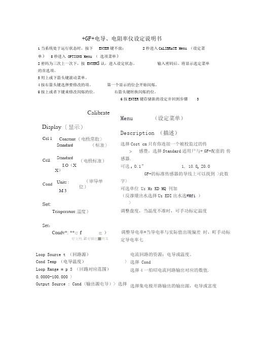
+GF+电导、电阻率仪设定说明书1当系统处于运行状态时,按下ENTER键不放:2秒进入CALIBRATE Menu (设定菜单)5秒进入 OPTIONS Menu (选项菜单)2密码为三次上一次下,按 ENTER S认,进入设定状态。
输入密码后。
将显示选定菜单的首选项。
3用上或下箭头键滚动菜单。
4按右箭头键选择要修改的项。
第一个显示的位会开始闪烁。
5按上或者下键来修改闪烁的位。
右箭头键转换闪烁的位。
6按ENTER键存储新的设定并回到步骤3Menu (设定菜单)Description (描述)选择Cost cm只有你连接一个被校监过的传>感豊,选择Standard适用尸与+ GF+配套的传感器.可选f0.1”1, 10.0p 20.0GF+的标准传感器的导线上可以找到>此数字〉可选单位Us Ms KD MQ 刊加(反滲壊出水选择Us EDI出水选#Mfi )>调整盘度,当温度不准时,可手功标定温度调整导电率*当导电率与实际值出现偏差时,町手动标定导电率七Loop Source t (回路源)Cond Temp (电导温度)〉Loop Range = p S (回路对应范围)0.0000-100.000 〉Output Source : Cond〈输出源电导)> 选择电流回路的资源:电导或温度。
选择 Cond选择4一船昭电流冋路输出对应的数值. 选择集电极开路输出的输出源,电导或富度Calibrate Display 〔显示)Cel 1Constant (电极常数〉Standard(标准〉CellStandardI.O(XX)(电极标准)Cond Units :M 3(审导单位)Set:Teiuperature 温度)Set:Condv*: **订f 也)好文档.it好蘇也■列x_<hitpnt Mode : (输出模式)可选Low (低》High (髙)pulse (脉冲)>□ulput SetpriL .:(设宦输出报警点)10. OOOOp S > Oitpirt Rys :(报警点灵敏度)0. b(XX)|l S > Out pi rt : p s10. 0000-40. 0000 >l^st Cal {疑后设岸H期)》选择樂由极开路输出的输出方式.包括High (高),Low (低〉或1E比洌“选网Off 时关闭・用以设楚臬电极开略输出的输出报警点用以设定集申极开路输岀报警戌的灵敏度选捧集电扱开路输出模式时设罡牒冲的起始伯和昱大输出点°如果徴变电与的单位,则此项擁须蛍新设定.用该頊记录莹要的H期*如毎年樂新验证或计划維护口期.21OPTIONS Menu (选项菜单)Display (显示)Description (描述)Cnntrnrit :〔对比度)调荃液晶显示的对比度° 1最睛,日最亮。
+GF+-SIGNET8850电导率变送器手册
+GF+ SIGNET8850-1 电导率/电阻率变送器警告:●接入输入输出线前请将电源断开。
●谨遵说明,以免人身伤害。
1.安装内置程序式传感器分为两类:面板安装式和就地安装式。
面板式传感器的安装需配备相关的五金器具,本手册包括了面板式安装的完整说明;就地式安装需一整套安装工具包,事实上只要有一套3-8050通用工具包就能够在任何地点安装传感器,该工具包内有就地安装的详细说明。
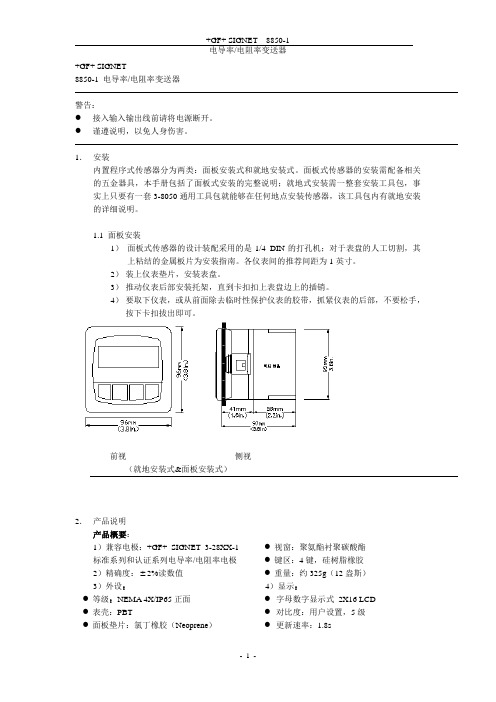
1.1 面板安装1)面板式传感器的设计装配采用的是1/4 DIN的打孔机;对于表盘的人工切割,其上粘结的金属板片为安装指南。
各仪表间的推荐间距为1英寸。
2)装上仪表垫片,安装表盘。
3)推动仪表后部安装托架,直到卡扣扣上表盘边上的插销。
4)要取下仪表,或从前面除去临时性保护仪表的胶带,抓紧仪表的后部,不要松手,按下卡扣拔出即可。
前视侧视(就地安装式&面板安装式)2.产品说明产品概要:1)兼容电极:+GF+ SIGNET 3-28XX-1标准系列和认证系列电导率/电阻率电极2)精确度: 2%读数值3)外设:●等级:NEMA 4X/IP65正面●表壳:PBT●面板垫片:氯丁橡胶(Neoprene)●视窗:聚氨酯衬聚碳酸酯●键区:4键,硅树脂橡胶●重量:约325g(12盎斯)4)显示:●字母数字显示式2X16 LCD ●对比度:用户设置,5级●更新速率:1.8s电气参数:●电源:12-24VDC 10%,可调,最大80mA传感器输入范围:●电导率:0.01 —400000 S/cm●电阻率:10K cm — 100M cmTDS:0.023 — 200000 PPM (可调 S/PPM)●温度:PT 1000,-25 — 120℃(-13 — 248℉);量程超过10M (低于0.1 S)时温度范围必须在20 — 100℃内●被动,独立,完全可调可逆转式4 — 20mA信号能各自输出电导率和温度●最大回路阻抗:最大50 @12V最大325 @18V最大600 @24V●更新速率:200ms●精确度: 0.03mA@25℃,24V开放式收集器输出,独立显示●最大50mA的衰减,最大上升到的电压30VDC●可编程项:●高低可调磁滞●脉冲运行(最大速率:400脉冲/分钟)环境条件:●运行温度:-10 —70℃(14 — 158℉)●存放温度:-15 —80℃(5 — 176℉)●相对湿度:0 — 95%,无冷凝●最大海拔:2000m(6562英尺)●绝缘类别:II●污染等级:2标准和认证:●CSA,CE,UL●免疫性:EN50082-2●放射性:EN55011,Class-B●在ISO9001和ISO14001标准下生产制造U.S.A.专利号#57083633. 电气接线警告:卸线前没有完全开启终端接线夹可能会永久性损坏设备。
8850-1eng 电导率表说明书
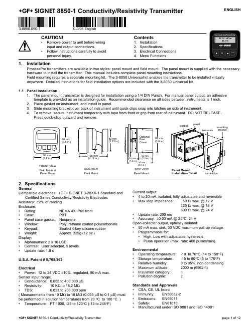
ENGLISH
3-8850.090-1
C-3/01 English
CAUTION!
• Remove power to unit before wiring input and output connections.
325 Ω max. @ 18 V 600 Ω max. @ 24 V • Update rate: 200 ms • Accuracy: ±0.03 mA @ 25°C, 24 V Open-collector output, optically isolated: • 50 mA max. sink, 30 VDC maximum pull-up voltage. • Programmable for: • High, Low with adjustable hysteresis • Pulse operation (max. rate: 400 pulses/min).
• Window:
Polyurethane coated polycarbonate
• Keypad:
Sealed 4-key silicone rubber
• Weight:
Approx. 325g (12 oz.)
Display:
• Alphanumeric 2 x 16 LCD
• Contrast: User selected, 5 levels
Environmental • Operating temperature: • Storage temperature: • Relative humidity: • Maximum altitude: • Insulation category: • Pollution degree:
gf电导率说明书

gf电导率说明书标题:GF电导率说明书引言:GF电导率是一种用于测量溶液中电导性的指标。
电导率是指当电流通过溶液时,溶液中的离子和电荷运动所导致的电导能力。
本说明书将详细介绍GF电导率的原理、使用方法以及注意事项。
1. 原理GF电导率是基于电导性的测量原理。
当电流通过溶液时,溶液中的离子会与电荷相互作用,导致电导现象的产生。
GF电导率仪通过测量电流通过溶液的能力来确定溶液的电导率。
电导率的单位是西门子/米(S/m),表示在1米长的导体中,电流通过时的电导能力。
2. 使用方法(1)准备工作:首先,确保GF电导率仪已经连接好电源,并且电极已经正确安装。
(2)校准仪器:在进行测量之前,需要对GF电导率仪进行校准,以确保测量结果的准确性。
校准方法请参考仪器的操作手册。
(3)测量操作:将电极浸入待测溶液中,确保电极完全浸入,并且不触碰容器的壁面。
等待一段时间,直到测量稳定。
(4)记录结果:测量稳定后,读取GF电导率仪上的显示数值,并记录下来。
可以根据需要进行单位换算。
(5)清洁和保养:使用完毕后,及时清洁电极,并储存于干燥、清洁的环境中,以保证下次使用时的准确性。
3. 注意事项(1)选择合适的电极:根据测量需求选择合适的电极,不同电极适用于不同的溶液测量。
(2)避免干扰:确保测量过程中没有外部电流干扰,如电磁场或其他电源设备。
(3)避免污染:在测量之前,确保电极已经清洁,并避免电极污染。
(4)避免温度影响:温度对电导率的测量结果有一定影响,因此在测量时应注意控制温度,并进行温度补偿。
(5)避免溶液浓度过高:浓度过高的溶液可能会对电极造成损坏,因此在测量时应根据电极的规格选择合适的溶液浓度。
4. 应用领域GF电导率广泛应用于水质分析、环境监测、化学实验等领域。
通过测量溶液的电导率,可以判断溶液中的离子浓度、溶解度、纯度等重要参数,为相关领域的研究和应用提供了便利。
结论:GF电导率作为一种测量溶液电导性的工具,具有简便、快速、准确的特点,被广泛应用于科学研究和工程实践中。
GF变送器操作说明书-中文版(8750-1-M-Chinese)
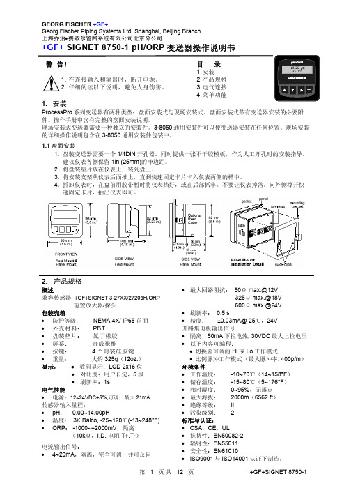
的详细操作说明包含在 3-8050 通用安装件包装中。
1.1 盘面安装 1. 盘装变送器需要一个 1/4DIN 开孔器。同时提供一张不干胶模板,作为人工开孔时的安装指导。 建议仪表各侧保留 1in.(25mm)的净边距。 2. 将盘装垫片放在仪表上,装到盘上。 3. 将安装支架从仪表后面推上,直到快速固定卡片卡入仪表两侧的槽中。 4. 拆卸仪表时,在盘前用胶带暂时将仪表挡好,或在后部抓牢。不要让仪表掉落。向外侧撑开快 速固定卡片,抽出仪表即可。
• 比例脉冲 开路集电极将根据标定菜单(CALIBRATE)中 设定的脉冲率,发出 100ms 宽的脉冲信号(见 第 6 页)。
• Low 当过程变量低于设定值时,输出信号被激励。 当流量值高于设定值加切换差时,输出信号复 位。
• High 当过程变量高于设定值时,输出信号被激励。 当流量值低于设定值加切换差时,输出信号复 位。
显示 4-20mA 的电流输出值。
Last CAL: 06-30-01
显示维护日程或最近的标定日期。
EASY
Easy Cal 功能是定期标定的快速而简单的方法。需要 4pH,
CAL: > 7pH,10pH 三种缓冲液中的任意两种。
第 4 页 共 12 页
+GF+SIGNET 8750-1
GEORG FISCHER +GF+
50 Ω max.@12V 325 Ωmax.@18V 600 Ωmax.@24V
端子 5~8:前置放大器电源与接地 5~6 是 8750 向前置放大器提供的直流电源 7~8 是传感器与接地线的接地端子
端子 3 与 4:开路集电极输出信号 晶体三极管输出,可编程设置以下内容(见 CALIBRATE 标定菜单): • 切换差可调的 High 或 Low 设定值 • 比例脉冲信号,最大值为 400p/m • 不用时可以隐藏(Off 状态)
GF-SIGNET-8550流量变送器操作说明书
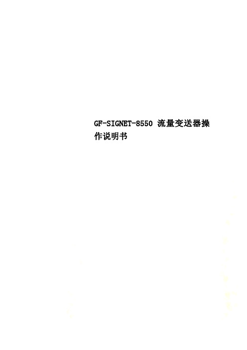
GF-SIGNET-8550流量变送器操作说明书+GF+ SIGNET 8550-1 流量变送器操作说明书注意:1 在连接输入和输出时,断开电源;2 细阅读以下说明,避免人身伤害。
目录1 安装2 性能指标3 电气接线4 菜单功能1 性能指标尺寸正视(盘装和现场安装) 侧视(现场安装) 侧视(现场安装8050) 侧视(现场安装8051)普通·适配型号:+GF+ SIGNET 流量传感器密封:·等级:NEMA 4X/IP65·外壳:PBT·盘装垫片:氯丁橡胶·屏幕:合成聚酯·按键:4个硅胶按键·重量:约325克显示:·2×16数字LCD·刷新速度:1秒·对比度:5个等级,可选择·显示精度:25ºC时读数的±0.5%·热敏偏移量:读数的±0.005%/ºC电气·电源:12-24VDC±10%,最大电流61mA传感器输入:·范围:0.5-1500Hz·传感器电源:2线:1.5mA@5VDC±10%3或4线:20mA@5VDC±10%·光电隔离·短路保护电流输出:·4-20mA,隔离,可调整且反向·最大回路阻抗:50Ω@12V,325Ω@18V,600Ω@24V·刷新速度:100ms·输出精度:±0.03mA集电极开路输出,光电隔离:·50mA最大下拉电流,30VDC最大上拉电压·可编程,对于·高,低,可调延时·脉冲(最大:300个脉冲/分钟)环境·运行温度:-10ºC-70ºC (14-158ºF)·保存温度:-15ºC-80ºC (5-176ºF)·相对湿度:0-95%,无露点·最大海拔:2000m(6562ft)·绝缘等级:Ⅱ·污染等级:2标准和认证·CSA,CE,UL·抗干扰性:EN50082-2·辐射:EN55011·安全:EN61010·ISO9001和ISO14001认证下制造2 安装ProcessPro变送器有两种安装方式:盘装和现场安装。
+GF+ SIGNET 8850-1 电导.电阻变送器操作说明书
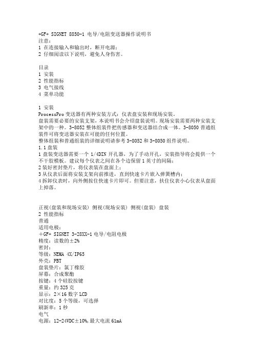
+GF+ SIGNET 8850-1 电导/电阻变送器操作说明书注意:1 在连接输入和输出时,断开电源;2 仔细阅读以下说明,避免人身伤害。
目录1 安装2 性能指标3 电气接线4 菜单功能1 安装ProcessPro变送器有两种安装方式:仪表盘安装和现场安装。
盘装需要必要的安装支架,本说明书会介绍盘装说明。
现场安装需要两种安装支架中的一种。
3-8052整体组装件把传感器和变送器结合成一体。
3-8050普通组装件可将变送器安装在可能的任何位置。
整体组装和普通组装的详细说明请参考3-8052和3-8050组件说明。
1.1盘装1盘装变送器需要一个1/4DIN开孔器,为了手动开孔,安装指导将会提供一个不干胶模板。
建议每个仪表之间在各个边保留1英寸的间隔;2装好密封垫片,将仪表装在盘面上;3从仪表后面将安装支架向前推进,直到快速卡片嵌入弹簧槽内;4拆卸仪表时,向外侧按住快速卡片即可。
但要注意,扶住仪表小心仪表从盘面上掉落。
正视(盘装和现场安装) 侧视(现场安装) 侧视(盘装) 盘装2 性能指标普通适用电极:+GF+ SIGNET 3-28XX-1电导/电阻电极精度:读数的±2%密封:等级:NEMA 4X/IP65外壳:PBT盘装垫片:氯丁橡胶屏幕:合成聚酯按键:4个硅胶按键重量:约325克显示:2×16数字LCD对比度:5个等级,可选择刷新率:1秒电气电源:12-24VDC±10%,最大电流61mA电极输入范围:电导:0.055-400,000us电阻:10KΩ-18.2MΩTDS:0.023-200,000ppm(测量范围在10 MΩ-18.2 MΩ时,介质温度在20-100℃)温度:PT1000-25℃-120℃ (-13-248°F)电流输出:4-20mA,隔离,可调整且反向最大回路阻抗:50 @12V,325 @18V,600 @24V刷新率:200ms输出精度:<a href="mailto:%C2%B10.03mA@25%E2%84%83,24V">±0.03mA@25℃,24V集电极开路输出,光电隔离:50mA最大下拉电流,30VDC最大上拉电压可编程对于Hi,Lo可调偏移量正比例脉冲(最大:400个脉冲/分钟)环境运行温度:-10oC-70oC (14-158oF)保存温度:-15oC-80oC (5-176oF)相对湿度:0-95%,无凝点最大海拔:2000m(6562ft)绝缘等级:Ⅱ污染等级:2标准和认证CSA,CE,UL抗干扰性:EN50082-2辐射:EN55011安全:EN61010ISO9001和ISO14001认证下制造3 电气接线注意:若在拆下接线前未完全按下端子柄,接线端子可能会损坏。
GF流量 电导 浊度安装条件及使用说明

II. 安装角度由于重力作用会加大转轮与轮轴间的摩擦,所以转轮流量计的运行受安装角度影响。
管道中的气泡与沉淀物会影响测量精度,严重时会阻碍转轮运行。
I. 管路上的安装位置• 流量计在管路上的正确安装位置可以保证得到正确的流态。
为了得到充分的湍流状态,在流量计上游预留充分的直管段长度是非常重要的。
这样稳定的流动状态可以保证转轮流量计准确测量。
• 下图阐示了安装塑料或金属转轮流量计时,推荐的上下游最小直管段长度。
• 在任何情况下,请尽可能选择流量计上游是无扰动的直管段。
注:仅提供了管径为DN15~DN300(1/2~12”)的K系数。
对于其它管径,请联系技术支持。
转轮流量计的竖管安装:• 为了保证流体是满管状态,流量计要安装在由下至上流向的管段上,在任何情况下,都推荐这种安装。
• 竖管安装时,一般不推荐流向朝下的方式。
转轮流量计的水平管安装:• 为了避免气泡的影响,推荐流量计安装在垂直线左右45度的位置。
更大的安装角度会使转轮与本体间的摩擦加大,在测量范围低端会影响流量计的性能。
• 正上方安装会因为气泡聚集在管道顶侧而使流量计受到干扰。
• 倒置安装会因为沉淀物聚集而卡住转轮。
因此如果管道中有沉淀物,一定不能在管道底部安装。
K系数:K系数(单位体积对应的脉冲数)的作用是将流量计输出的频率信号折算成流量值。
Signet提供的所有流量计的K系数值对应的体积单位只有加仑(Gallon)与升(Liter)。
对不同的管径,不同的管材,以及不同种类的安装件,K系数都是不同的。
对于除了水以外的其它流体,K系数需要在现场进行设置。
流量计安装提示• 为了保证流量计插入到正确位置,请使用Signet专用安装件。
• 流量计上游直管段的推荐长度是用管道内径(I .D .)的倍数表示的。
要注意,根据流量计上游阻流设备的不同,这个倍数也是不同的。
• 转轮流量计可以用在类水的流体中,但要保证流体不含颗粒物(颗粒物直径<100微米)、不含铁屑、无污垢。
8850-2电导变送器8850-2P仪表使用说明
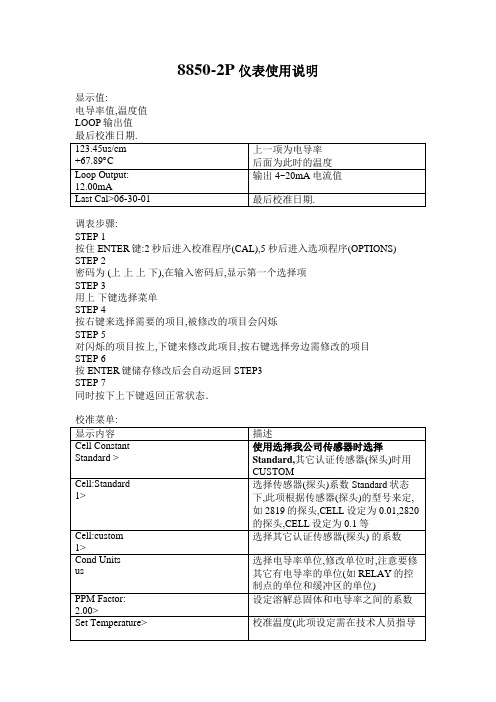
8850-2P仪表使用说明显示值:电导率值,温度值LOOP输出值调表步骤:STEP 1按住ENTER键:2秒后进入校准程序(CAL),5秒后进入选项程序(OPTIONS) STEP 2密码为 (上上上下),在输入密码后,显示第一个选择项STEP 3用上下键选择菜单STEP 4按右键来选择需要的项目,被修改的项目会闪烁STEP 5对闪烁的项目按上,下键来修改此项目,按右键选择旁边需修改的项目STEP 6按ENTER键储存修改后会自动返回STEP3STEP 7同时按下上下键返回正常状态.一关于RELAY(继电器)的设定举例说:想设定电导率在10ms以下, 继电器开始工作,通过电磁阀(或其它阀门)控制加入液体,当电导率达到10.5ms, 继电器停止工作,暂停加入液体.1 将Relay 1 source设为Cond,此项设置表示将电导率作为继电器的信号源2将Relay 1 Mode设为Low,此项设置表示将继电器的工作模式设为低点模式3将Relay 1 Setpoint设为10ms此项设置表示将继电器的工作点设置为10ms4将Relay 1 Hys设为0.5ms此项设置表示将继电器的缓冲设置为0.5ms,即电导率在10.5时继电器暂停工作.5 同理,如想想设定电导率在9ms以下, 继电器开始工作,通过电磁阀(或其它阀门)控制加入液体,当电导率达到9.2ms, 继电器停止工作,暂停加入液体.可将第3步Relay 1 Setpoint设为9ms,再将第4步Relay 1 Hys设为0.2ms.二关于CELL(探头系数)的选择,请参照CELL的设置来确定2819的探头,CELL设定为0.01,2820的探头,CELL设定为0.1,2821的探头,CELL设定为1,2822的探头,CELL设定为102823的探头, CELL设定为20.。
- 1、下载文档前请自行甄别文档内容的完整性,平台不提供额外的编辑、内容补充、找答案等附加服务。
- 2、"仅部分预览"的文档,不可在线预览部分如存在完整性等问题,可反馈申请退款(可完整预览的文档不适用该条件!)。
- 3、如文档侵犯您的权益,请联系客服反馈,我们会尽快为您处理(人工客服工作时间:9:00-18:30)。
+GF+ SIGNET8850-1 电导率/电阻率变送器 警告: ● 接入输入输出线前请将电源断开。
● 谨遵说明,以免人身伤害。
1. 安装内置程序式传感器分为两类:面板安装式和就地安装式。
面板式传感器的安装需配备相关的五金器具,本手册包括了面板式安装的完整说明;就地式安装需一整套安装工具包,事实上只要有一套3-8050通用工具包就能够在任何地点安装传感器,该工具包内有就地安装的详细说明。
1.1 面板安装1) 面板式传感器的设计装配采用的是1/4 DIN 的打孔机;对于表盘的人工切割,其上粘结的金属板片为安装指南。
各仪表间的推荐间距为1英寸。
2) 装上仪表垫片,安装表盘。
3) 推动仪表后部安装托架,直到卡扣扣上表盘边上的插销。
4) 要取下仪表,或从前面除去临时性保护仪表的胶带,抓紧仪表的后部,不要松手,按下卡扣拔出即可。
前视 侧视(就地安装式&面板安装式)2. 产品说明产品概要:1)兼容电极:+GF+ SIGNET 3-28XX-1标准系列和认证系列电导率/电阻率电极 2)精确度: 2%读数值 3)外设:● 等级:NEMA 4X/IP65正面 ● 表壳:PBT● 面板垫片:氯丁橡胶(Neoprene )● 视窗:聚氨酯衬聚碳酸酯 ● 键区:4键,硅树脂橡胶 ● 重量:约325g (12盎斯) 4)显示:● 字母数字显示式 2X16 LCD ● 对比度:用户设置,5级 ● 更新速率:1.8s电气参数:●电源:12-24VDC610%,可调,最大80mA传感器输入范围:●电导率:0.01 —400000μS/cm●电阻率:10Kς.cm — 100Mς.cmTDS:0.023 — 200000 PPM (可调μS/PPM)●温度:PT 1000,-25 — 120℃(-13 — 248℉);量程超过10Mς(低于0.1μS)时温度范围必须在20 — 100℃内●被动,独立,完全可调可逆转式4 — 20mA信号能各自输出电导率和温度●最大回路阻抗:最大50ς @12V最大325ς @18V最大600ς @24V●更新速率:200ms●精确度:60.03mA@25℃,24V开放式收集器输出,独立显示●最大50mA的衰减,最大上升到的电压30VDC●可编程项:●高低可调磁滞●脉冲运行(最大速率:400脉冲/分钟)环境条件:●运行温度:-10 —70℃(14 — 158℉)●存放温度:-15 —80℃(5 — 176℉)●相对湿度:0 — 95%,无冷凝●最大海拔:2000m(6562英尺)●绝缘类别:II●污染等级:2标准和认证:●CSA,CE,UL●免疫性:EN50082-2●放射性:EN55011,Class-B●在ISO9001和ISO14001标准下生产制造U.S.A.专利号#57083633. 电气接线警告:卸线前没有完全开启终端接线夹可能会永久性损坏设备。
接线步骤:1)除去电线终端绝缘皮0.5 — 0.625 In.(13—16mm)2) 用一把小螺丝刀按下橙色接线控制杠直至打开终端接线夹 3)将裸线(无绝缘皮)端插入接线孔直至触底4)松开橙色接线控制杆确保线到位。
轻轻地拽线,确保接线牢固。
卸线步骤:1) 用一把小螺丝刀按下橙色接线控制杆打开终端接线夹 2) 接线夹全开后,拔下电线布线提示:● 不要将传感器电缆和AC (交流电)电源线置于同一线管内,电磁干扰将影响传感器的信号。
● 将传感器电缆置于地下金属线管内有助于屏蔽电磁干扰和防止机械性的损坏。
● 包好电缆接头防止因潮湿引起的腐蚀。
● 每一终端接线孔只能接一根线。
如若有双线,请在接线孔外接合。
12 3 478 9 10]3.1传感器输入接线接线端+GF+ SIGNET 28XX-1 8850-1电导率/电阻率 变送器 标准电极和认证电极 根据应用条件选择探头的量程范围● 2819-1,2839-1(0.01单位):0.01至100μS (10至100M ς)56接线端5-6:开放式采集器输出● 变送器输出;可调整的高、低设置点,带有可调的滞后值和比例脉冲(最大400脉冲/分钟) ● 未使用时无效2819-1和2839-1适用于所有的电阻率条件●2820-1,2840-1((0.1单位):1至100μS●2821-1,2841-1(1.0单位):10至10000μS●2822-1,2842-1(10单位):100至200000μS ●2823-1(20单位):200至400000μS3.2系统电源/回路连接;单机应用,未用电流回路连接到PLC/记录器,各自提供所有的8850系统均需辅助电源连接至带内置电源的PLC中;例如;两个变送器连接到带电源的PLC/记录器中3.3 开放式输出连接当实际值超过设定值时,电闸会作出反应,或者产生脉冲信号,自动打开输出连接。
低点:当实际值小于设定值时引发输出。
当实际值移动到正的滞后值时。
将停止输出。
高点:当实际值大于设定值时引发输入。
当实际值移动到正的滞后点时。
将停止输入。
脉冲调整根据校准菜单中的设置速率,开放式收集器将产生一个100mS的脉冲。
举例如下●PH值小于5.0时,输出值为0ms/min●PH值为7.5时输出值为50ms/min●PH值超过10时输出值为100ms/min启动点、终点和最大的脉冲速率在校准菜单中可选。
VIEW 菜单进行一般操作时,显示查看菜单当使用校准菜单和选项菜单时,假如在10分钟内没有行动,将回到查看菜单当你想显示选项时,按上键或下键进行选择。
选项将循环滚动。
改变子选项不会中断系统菜单。
查看菜单不能编辑输出设置VIEW 菜单内置程序编辑步骤:第一步;按ENTER键进入菜单按2秒钟进入校正菜单按5秒钟进入选项菜单第二步;密码顺序上-上-上-下输入密码后,将显示选择菜单中的第一条第三步;按上下键循环滚动菜单第四步;按右键进入选择菜单项编辑首位字符将开始闪光第五步;按上下键编辑闪光字符按右键进入下个闪光点第六步;按Enter键保存设置并回到第三步第一步注意事项;查看菜单是常规显示校准菜单和选项菜单需要密码第二步注意事项:显示Enter key code 后,假如5分钟内不输入密码将回到查看菜单第三步和第四步注意事项:●参照后面完整的列表菜单项及其功用●第三步后,同时按上下键回到查看菜单项●假如10分钟后没有动作,也将回到查看菜单选项第三步:完成闪光?保存刚才设置后,同时按上下键回到一般操作。
第5/6步注意●在编辑的时候,所有的输出功能都保持有效●只有闪光字符能够编辑●按右键,闪光点进入下一个字符●设置好的数据在按下ENTER键时立刻起效●假如10分钟没有按键,将保存刚才的设置并回到第三步●第6步(按ENTER键)总是返回到第三步●重复第三步至第6步直到编辑完成第五步;出现误差?任一字符闪光时,同时按上下键,将取消刚才编辑的保存值并且回到第三步。
该装置在工厂中已经使用了电子校准。
●步骤A是利用确定精度(60.1%)的电阻来模拟温度和电导率,以此来校验仪表的精度和线性;●步骤B为湿式校准。
该步骤用到了传感器输入和NIST追踪测试溶液。
一旦出错,该步骤能提供最大限度的精确系统校正。
A)利用精确电阻进行精度确认(电极校准)1模拟温度温度输入到8850用的是PT-1000热电偶,其中1000欧姆等于0℃,并且每改变3.84欧姆等于1℃的改变。
(1000ς=0℃,1003.84ς=1.0℃,1007.68ς=2.0℃,…………1096ς=25℃)●在”温度输入”和”隔离信号接地”接线端连入一电阻(1000ς到1096ς)●设置温度;根据测出的电阻值调整温度到相应的精确值。
(见编辑步骤,校准菜单)●接入第二个不同阻值的电阻,确认温度值的线性●假如仪表不能显示正确的值,需要送修。
(60.5℃)2 模拟电导率模拟某一特定的电导率需计算出精确的电阻率,或者根据一个电阻值计算出准确的电导率:电阻率=常数单位/电导率(Siemens) e.g. 0.1单位/0.000020(Siemens)=5000ς或5.0kς电阻率=传感器单位/模拟电阻(ς) e.g. 0.1单位/100.000(ς)=0.000001Siemens或1μS /cm (1μS /cm=1×10-6 Siemens 或0.000001Siemens)●在“信号输入”端和“隔离信号接地”端连入电导率电阻●设置电导率:根据电阻值调节电导率值。
(见编辑步骤和校准菜单)●接入第二个不同阻值的电阻,确认仪表的线性●假如仪表不能显示正确的值(62%读数),需要送修。
B)用NIST追踪溶液进行湿式校准:使用NIST追踪标准时,仔细察看随测试溶液一起提供的温度信息。
注意要防止测试溶液的污染。
传感器必须处于该测试溶液标签中指定的温度下。
●从系统中取下传感器,用少量测试溶液冲洗传感器。
●将传感器置于测试溶液中●将一支参比温度计置于同一溶液中●允许提供充足的时间待温度恒定。
●设置温度:根据参比温度计调节温度值(见编辑步骤)●设置电导率:根据测试溶液的温度值调节电导率值(见编辑步骤)●将传感器置于第二个不同温度值的测试溶液中,确认其线性●假如仪表不能显示正确的值(温度60.5℃,电导率62%读数),需要送修。
温度系数电导率的测量高度依赖于温度。
该依赖性可以表述为每℃所引起的相对变化,通常写作%/℃(变化始于25℃),或者溶液的斜率依据程序溶液的类型,斜率变化显著。
出厂时的默认温度补偿系数为 2.00%/℃。
程序溶液需调到最大准确度。
给程序选定出合适的温度补偿系数:1)输入0.00清除8850的温度补偿系数2)加热样本溶液至接近程序温度的最大值。
将传感器置于样本溶液中,等待几分钟至稳定。
进入察看菜单,将显示的温度和电导率值记录在下列空格中显示温度:T1 = ℃显示电导率:C1 = μS(不要将该步骤用于电导率为0.055μS 至0.1μS的溶液中,有一条内在的纯水曲线适用于该范围。
此范围应该使用出厂默认设置(2.00%/℃))3)冷却样本溶液至接近程序温度的最小值。
将传感器置于样本溶液中,等待几分钟至稳定。
进入察看菜单,将显示的温度和电导率值记录在下列空格中显示温度:T2 = ℃显示电导率:C2 = μS(推荐第二步和第三步间的电导率变化为10%)4)将第二步和第三步的记录读数代入下式中100×(C2 -C1 )TC=(C2×(T1-25)) – (C1×(T2-25))例:样本溶液测得电导率为205μS@48℃,冷却后测得电导率为150μS@23℃。
(C1 =205 ,T1 =48,C2 =150,T2 =23)TC计算如下:100×(205-150)TC= =1.42%/℃(150×(48-25)) – (205×(23-25))PPM系数当选择PPM显示单位时,该特征才适用。
