SC50VB160-G;中文规格书,Datasheet资料
赛米控丹佛斯电子 SEMiX302GB12E4s 数据表

SEMiX ®2sTrench IGBT ModulesSEMiX302GB12E4sFeatures•Homogeneous Si•Trench = Trenchgate technology •V CE(sat) with positive temperature coefficient•High short circuit capability •UL recognized, file no. E63532Typical Applications*•AC inverter drives •UPS•Electronic WeldingRemarks•Case temperature limited to T C =125°C max.•Product reliability results are valid for T j =150°C•Dynamic values apply to thefollowing combination of resistors: R Gon,main = 0,5 Ω R Goff,main = 0,5 Ω R G,X = 2,2 Ω R E,X = 0,5 ΩAbsolute Maximum Ratings SymbolConditions Values UnitIGBT V CES T j =25°C 1200V I C T j =175°CT c =25°C 463A T c =80°C356A I Cnom 300A I CRMI CRM = 3xI Cnom 900A V GES -20...20V t psc V CC =800V V GE ≤ 20V V CES ≤ 1200VT j =150°C10µs T j-40...175°C Inverse diode I F T j =175°CT c =25°C 356A T c =80°C 266A I Fnom300A I FRM I FRM = 3xI Fnom900A I FSM t p =10ms, sin 180°, T j =25°C1620A T j -40 (175)°C Module I t(RMS)T terminal =80°C600A T stg -40...125°C V isolAC sinus 50Hz, t =1min4000VCharacteristics SymbolConditions min.typ.max.UnitIGBT V CE(sat)I C =300A V GE =15V chiplevel T j =25°C 1.8 2.05V T j =150°C 2.2 2.4V V CE0chiplevel T j =25°C 0.80.9V T j =150°C 0.70.8V r CE V GE =15V chiplevel T j =25°C 3.3 3.8m ΩT j =150°C5.0 5.3m ΩV GE(th)V GE =V CE , I C =12mA55.86.5V I CES V GE =0V V CE =1200V T j =25°C 4.0mA T j =150°C mA C ies V CE =25V V GE =0Vf =1MHz 18.6nF C oes f =1MHz 1.16nF C res f =1MHz1.02nF Q G V GE =- 8 V...+ 15 V 1700nC R Gint T j =25°C2.50Ωt d(on)V CC =600V I C =300A V GE =±15V R G on =1.9ΩR G off =1.9Ωdi/dt on =5000A/µs di/dt off =2800A/µs T j =150°C 282ns t r T j =150°C 60ns E on T j =150°C 30mJ t d(off)T j =150°C 564ns t f T j =150°C 117ns E off T j =150°C 44mJ R th(j-c)per IGBT0.096K/WCharacteristicsSymbol Conditions min.typ.max.UnitInverse diodeV F = V EC I F=300AV GE=0Vchiplevel T j=25°C 2.1 2.46V T j=150°C 2.1 2.4VV F0chiplevel T j=25°C 1.1 1.3 1.5V T j=150°C0.70.9 1.1Vr Fchiplevel T j=25°C 2.2 2.8 3.2mΩT j=150°C 3.3 3.9 4.3mΩI RRM I F=300Adi/dt off=4300A/µsV GE=-15VV CC=600V T j=150°C230AQ rr T j=150°C50µC E rr T j=150°C19mJ R th(j-c)per diode0.17K/W ModuleL CE18nHR CC'+EE'res., terminal-chip T C=25°C0.7mΩT C=125°C1mΩR th(c-s)per module0.045K/W M s to heat sink (M5)35Nm M t to terminals (M6) 2.55NmNm w250g Temperature SensorR100T c=100°C (R25=5 kΩ)493 ± 5%ΩB100/125R(T)=R100exp[B100/125(1/T-1/T100)]; T[K];3550±2%KSEMiX® 2sTrench IGBT Modules SEMiX302GB12E4sFeatures•Homogeneous Si•Trench = Trenchgate technology•V CE(sat) with positive temperature coefficient•High short circuit capability•UL recognized, file no. E63532Typical Applications*•AC inverter drives•UPS•Electronic WeldingRemarks•Case temperature limited to T C=125°C max.•Product reliability results are valid for T j=150°C•Dynamic values apply to thefollowing combination of resistors:R Gon,main = 0,5 ΩR Goff,main = 0,5 ΩR G,X = 2,2 ΩR E,X = 0,5 ΩFig. 1: Typ. output characteristic, inclusive R CC'+ EE'Fig. 2: Rated current vs. temperature I C = f (T C )Fig. 3: Typ. turn-on /-off energy = f (I C )Fig. 4: Typ. turn-on /-off energy = f (R G )Fig. 5: Typ. transfer characteristic Fig. 6: Typ. gate charge characteristicFig. 7: Typ. switching times vs. I C Fig. 8: Typ. switching times vs. gate resistor R GFig. 9: Typ. transient thermal impedance Fig. 10: Typ. CAL diode forward charact., incl. R CC'+ EE'Fig. 11: Typ. CAL diode peak reverse recovery current Fig. 12: Typ. CAL diode recovery chargeThis is an electrostatic discharge sensitive device (ESDS), international standard IEC 60747-1, Chapter IX* The specifications of our components may not be considered as an assurance of component characteristics. Components have to be tested for the respective application. Adjustments may be necessary. The use of SEMIKRON products in life support appliances and systems is subject to prior specification and written approval by SEMIKRON. We therefore strongly recommend prior consultation of our staff.。
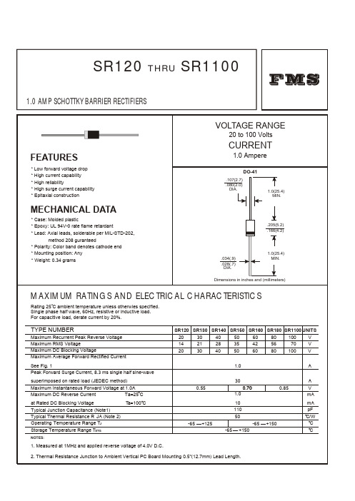
SR160 肖特基二极管
1.5
18
Tj=25 C 8.3ms Single Half Sine Wave JEDEC method
FORWARD VOLT AGE,(V)
12
6
FIG.5 - TYPICAL REVERSE
0 1 5 10 50 100
CHARACTERISTICS 100
NUMBER OF CYCLES AT 60Hz
.034(.9) .028(.7) DIA. .205(5.2) .166(4.2)
1.0(25.4) MIN.
Dimensions in inches and (millimeters)
MAXIMUM RATINGS AND ELECTRICAL CHARACTERISTICS
Rating 25 C ambient temperature uniess otherwies specified. Single phase half wave, 60Hz, resistive or inductive load. For capacitive load, derate current by 20%.
FIG.4-TYPICAL JUNCTION CAPACITANCE
350 300 250 200 150 100 50 0
JUNCTION CAPACITANCE,(pF)
REVERSE LEAKAGE CURRENT, (mA)
10
1.0
Tj=75 C
.1
Tj=25 C
.01
.05
.1
.5
1
5
10
1.2 1.0
50
INSTANTANEOUS FORWARD CURRENT,(A)
C1608C0G1H331J资料
REMINDERSPlease read this before using the product.SAFETY REMINDERSREMINDERS1. If you intend to use a product listed in this catalog for a purpose that may cause loss of life or other damage, you must contact our company’s sales window.2. We may modify products or discontinue production of a product listed in this catalog without prior notification.3. We provide “Delivery Specification” that explain precautions for the specifications and safety of each product listed in this cata-log. We strongly recommend that you exchange these delivery specifications with customers that use one of these products.4. If you plan to export a product listed in this catalog, keep in mind that it may be a restricted item according to the “Foreign Exchange and Foreign Trade Control Law”. In such cases, it is necessary to acquire export permission in harmony with this law.5. Any reproduction or transferring of the contents of this catalog is prohibited without prior permission from our company.6. We are not responsible for problems that occur related to the intellectual property rights or other rights of our company or a third party when you use a product listed in this catalog. We do not grant license of these rights.7. This catalog only applies to products purchased through our company or one of our company’s official agencies. This catalog does not apply to products that are purchased through other third parties.8. The descriptions in this catalog apply as of April 2007.General Multilayer Ceramic Chip Capacitors C Series C1608 (EIA CC0603) TypeFEATURES•High capacitance has been achieved through precision technologies that enable the use of multiple thinner ceramic dielectric layers.• A monolithic structure ensures superior mechanical strength and reliability.•High-accuracy automatic mounting is facilitated through the maintenance of very precise dimensional tolerances.•Composed of only ceramics and metals, these capacitors provide extremely dependable performance, exhibiting virtually no degradation even when subjected to temperature extremes.•Low stray capacitance ensures high conformity with nominal values, thereby simplifying the circuit design process.•Low residual inductance assures superior frequency characteristics.•Because electrostatic capacity has been obtained up to the electrolytic capacitor range, these capacitors offer long service life and are optimally suited for power supply designs that require high levels of reliability.•Owing to their low ESR and excellent frequency characteristics, these products are optimally suited for high frequency and high-density type power supplies.SHAPES AND DIMENSIONS PRODUCT IDENTIFICATION(1) Series name(2) Dimensions L×W(3) Capacitance temperature characteristicsClass 1 (T emperature compensation)Class 2 (T emperature stable and general purpose)(4) Rated voltage Edc(5) Nominal capacitanceThe capacitance is expressed in three digit codes and in units of pico farads (pF).The first and second digits identify the first and second significant figures of the capacitance.The third digit identifies the multiplier.R designates a decimal point.(6) Capacitance tolerance(7) Packaging styleConformity to RoHS DirectiveC1608CH1H100D(1)(2)(3)(4)(5)(6)(7)1608 1.6×0.8mmT emperaturecharacteristicsCapacitance change Temperature rangeCH0±60ppm/°C–25 to +85°CSL+350 to –1000ppm/°C+20 to +85°CT emperaturecharacteristicsCapacitance change Temperature rangeJB±10%–25 to +85°CJF+30, –80%–25 to +85°CX7R±15%–55 to +125°CX5R±15%–55 to +85°CY5V+22, –82%–30 to +85°C1A10V1C16V1H50V0101pF10010pF1021,000pF0R50.5pFSymbol T oleranceApplicable capacitancerangeC±0.25pF10pF or lessJ±5%Over 10pFK±10%Z+80, –20%T T aping (reel)B Bulk•Conformity to RoHS Directive: This means that, in conformity with EU Directive 2002/95/EC, lead, cadmium, mercury, hexavalent chromium, and specific bromine-based flame retardants, PBB and PBDE, have not been used, except for exempted applications.CAPACITANCE RANGES: CLASS 1 (TEMPERATURE COMPENSATION)TEMPERATURE CHARACTERISTICS: CH(0±60ppm/°C), C0G(0±30ppm/°C)RATED VOLTAGE Edc: 50V TEMPERATURE CHARACTERISTICS: SL(+350 to –1000ppm/ )RATED VOLTAGE Edc: 10VCAPACITANCE RANGES: CLASS 2TEMPERATURE CHARACTERISTICS: JB(±10%), X5R/X7R(±15%)RATED VOLTAGE Edc: 50VCapacitance(pF)ToleranceThickness T (mm)Part No.T emperature characteristics: CH T emperature characteristics: C0G 0.5 ±0.25pF 0.8±0.10C1608CH1H0R5C C1608C0G1H0R5C 0.75 ±0.25pF 0.8±0.10C1608CH1HR75C C1608C0G1HR75C 1 ±0.25pF 0.8±0.10C1608CH1H010C C1608C0G1H010C 1.5 ±0.25pF 0.8±0.10C1608CH1H1R5C C1608C0G1H1R5C 2 ±0.25pF 0.8±0.10C1608CH1H020C C1608C0G1H020C 3 ±0.25pF 0.8±0.10C1608CH1H030C C1608C0G1H030C 4 ±0.25pF 0.8±0.10C1608CH1H040C C1608C0G1H040C 5 ±0.25pF 0.8±0.10C1608CH1H050C C1608C0G1H050C 6 ±0.5pF 0.8±0.10C1608CH1H060D C1608C0G1H060D 7 ±0.5pF 0.8±0.10C1608CH1H070D C1608C0G1H070D 8 ±0.5pF 0.8±0.10C1608CH1H080D C1608C0G1H080D 9 ±0.5pF 0.8±0.10C1608CH1H090D C1608C0G1H090D 10 ±0.5pF 0.8±0.10C1608CH1H100D C1608C0G1H100D 12 ±5%0.8±0.10C1608CH1H120J C1608C0G1H120J 15 ±5%0.8±0.10C1608CH1H150J C1608C0G1H150J 18 ±5%0.8±0.10C1608CH1H180J C1608C0G1H180J 22 ±5%0.8±0.10C1608CH1H220J C1608C0G1H220J 27 ±5%0.8±0.10C1608CH1H270J C1608C0G1H270J 33 ±5%0.8±0.10C1608CH1H330J C1608C0G1H330J 39 ±5%0.8±0.10C1608CH1H390J C1608C0G1H390J 47 ±5%0.8±0.10C1608CH1H470J C1608C0G1H470J 56 ±5%0.8±0.10C1608CH1H560J C1608C0G1H560J 68 ±5%0.8±0.10C1608CH1H680J C1608C0G1H680J 82 ±5%0.8±0.10C1608CH1H820J C1608C0G1H820J 100 ±5%0.8±0.10C1608CH1H101J C1608C0G1H101J 120±5%0.8±0.10C1608CH1H121J C1608C0G1H121J 150 ±5%0.8±0.10C1608CH1H151J C1608C0G1H151J 180±5%0.8±0.10C1608CH1H181J C1608C0G1H181J 220 ±5%0.8±0.10C1608CH1H221J C1608C0G1H221J 270±5%0.8±0.10C1608CH1H271J C1608C0G1H271J 330 ±5%0.8±0.10C1608CH1H331J C1608C0G1H331J 390±5%0.8±0.10C1608CH1H391J C1608C0G1H391J 470 ±5%0.8±0.10C1608CH1H471J C1608C0G1H471J 560±5%0.8±0.10C1608CH1H561J C1608C0G1H561J 680 ±5%0.8±0.10C1608CH1H681J C1608C0G1H681J 820±5%0.8±0.10C1608CH1H821J C1608C0G1H821J 1,000 ±5%0.8±0.10C1608CH1H102J C1608C0G1H102J 1,500 ±5%0.8±0.10C1608CH1H152J C1608C0G1H152J 2,200 ±5%0.8±0.10C1608CH1H222J C1608C0G1H222J 3,300 ±5%0.8±0.10C1608CH1H332JC1608C0G1H332JCapacitance (pF)Tolerance Thickness T (mm)Part No.T emperature characteristics: SL 15,000±5%0.80±0.10C1608SL1A153J 22,000±5%0.80±0.10C1608SL1A223JCapacitance(pF)ToleranceThickness T (mm)Part No.T emperature characteristics: JB T emperature characteristics: X5R Temperature characteristics: X7R 10,000 ±10%0.8±0.10C1608JB1H103KC1608X5R1H103K C1608X7R1H103K15,000 ±10%0.8±0.10C1608JB1H153KC1608X5R1H153K C1608X7R1H153K 22,000 ±10%0.8±0.10C1608JB1H223K C1608X5R1H223K C1608X7R1H223K 33,000 ±10%0.8±0.10C1608JB1H333KC1608X5R1H333K C1608X7R1H333K 47,000 ±10%0.8±0.10C1608JB1H473KC1608X5R1H473K C1608X7R1H473K 68,000 ±10%0.8±0.10C1608JB1H683KC1608X5R1H683K C1608X7R1H683K 100,000±10%0.8±0.10C1608JB1H104K C1608X5R1H104K C1608X7R1H104K ±20%0.8±0.10C1608JB1H104MC1608X5R1H104MC1608X7R1H104MRATED VOLTAGE Edc: 16VTEMPERATURE CHARACTERISTICS: JB(±10%), X5R(±15%)RATED VOLTAGE Edc: 25VRATED VOLTAGE Edc: 16VRATED VOLTAGE Edc: 10VRATED VOLTAGE Edc: 6.3VTEMPERATURE CHARACTERISTICS: JF(+30, –80%), Y5V(+22, –82%)RATED VOLTAGE Edc: 50VT emperature characteristics: JB T emperature characteristics: X5R Temperature characteristics: X7R 150,000 ±10%0.8±0.10C1608JB1E154K C1608X5R1E154K C1608X7R1E154K ±20%0.8±0.10C1608JB1E154M C1608X5R1E154M C1608X7R1E154M 220,000 ±10%0.8±0.10C1608JB1E224K C1608X5R1E224K C1608X7R1E224K ±20%0.8±0.10C1608JB1E224M C1608X5R1E224M C1608X7R1E224M 330,000±10%0.8±0.10C1608JB1E334K C1608X5R1E334K C1608X7R1E334K ±20%0.8±0.10C1608JB1E334MC1608X5R1E334MC1608X7R1E334MCapacitance (pF)Tolerance Thickness T (mm)Part No.T emperature characteristics: JB T emperature characteristics: X5R Temperature characteristics: X7R 470,000 ±10%0.8+0.15, –0.1C1608JB1C474K C1608X5R1C474K C1608X7R1C474K ±20%0.8+0.15, –0.1C1608JB1C474M C1608X5R1C474M C1608X7R1C474M 680,000 ±10%0.8+0.15, –0.1C1608JB1C684K C1608X5R1C684K C1608X7R1C684K ±20%0.8+0.15, –0.1C1608JB1C684M C1608X5R1C684M C1608X7R1C684M 1,000,000±10%0.8+0.2, –0.1C1608JB1C105K C1608X5R1C105K C1608X7R1C105K ±20%0.8+0.2, –0.1C1608JB1C105MC1608X5R1C105MC1608X7R1C105MCapacitance (pF)Tolerance Thickness T (mm)Part No.T emperature characteristics: JB T emperature characteristics: X5R 470,000±10%0.80±0.10C1608JB1E474K C1608X5R1E474K ±20%0.80±0.10C1608JB1E474M C1608X5R1E474M 680,000±10%0.80±0.10C1608JB1E684K C1608X5R1E684K ±20%0.80±0.10C1608JB1E684M C1608X5R1E684M 1,000,000±10%0.80±0.10C1608JB1E105K C1608X5R1E105K ±20%0.80±0.10C1608JB1E105MC1608X5R1E105MCapacitance (pF)Tolerance Thickness T (mm)Part No.T emperature characteristics: JB T emperature characteristics: X5R 1,500,000 ±10%0.8±0.10C1608JB1C155K C1608X5R1C155K ±20%0.8±0.10C1608JB1C155M C1608X5R1C155M 2,200,000±10%0.8±0.10C1608JB1C225K C1608X5R1C225K ±20%0.8±0.10C1608JB1C225MC1608X5R1C225MCapacitance (pF)Tolerance Thickness T (mm)Part No.T emperature characteristics: JB T emperature characteristics: X5R 3,300,000 ±10%0.8±0.10C1608JB1A335K C1608X5R1A335K ±20%0.8±0.10C1608JB1A335M C1608X5R1A335M 4,700,000±10%0.8±0.10C1608JB1A475K C1608X5R1A475K ±20%0.8±0.10C1608JB1A475MC1608X5R1A475MCapacitance (pF)Tolerance Thickness T (mm)Part No.T emperature characteristics: JB T emperature characteristics: X5R 6,800,000 ±10%0.80+0.15,–0.10C1608JB0J685K C1608X5R0J685K ±20%0.80+0.15,–0.10C1608JB0J685M C1608X5R0J685M 10,000,000±10%0.80+0.15,–0.10C1608JB0J106K C1608X5R0J106K ±20%0.80+0.20,–0.10C1608JB0J106MC1608X5R0J106MCapacitance(pF)ToleranceThickness T (mm)Part No.T emperature characteristics: JF T emperature characteristics: Y5V 100,000 +80,–20%0.8±0.10C1608JF1H104Z C1608Y5V1H104Z 220,000 +80,–20%0.8±0.10C1608JF1H224Z C1608Y5V1H224Z 470,000 +80,–20%0.8±0.10C1608JF1H474ZC1608Y5V1H474ZRATED VOLTAGE Edc: 16V RATED VOLTAGE Edc: 6.3V T emperature characteristics: JF T emperature characteristics: Y5V1,000,000 +80,–20%0.8±0.10C1608JF1E105Z C1608Y5V1E105ZCapacitance (pF)ToleranceThickness T(mm)Part No.T emperature characteristics: JF T emperature characteristics: Y5V2,200,000 +80,–20%0.8±0.10C1608JF1C225Z C1608Y5V1C225ZCapacitance (pF)ToleranceThickness T(mm)Part No.T emperature characteristics: JF T emperature characteristics: Y5V4,700,000 +80,–20%0.8±0.10C1608JF0J475Z C1608Y5V0J475Z 10,000,000 +80,–20%0.8+0.15,–0.10C1608JF0J106Z C1608Y5V0J106Z • For more information about the products of other capacitance or data, please contact us.。
XC161CJ资料
XC161CJ资料元器件交易网Data Sheet, V2.3, March 2022年__-16F16-Bit Single-Chip Microcontroller withC166SV2 CoreMicrocontrollers元器件交易网Edition 2022年-03Published byInfineon Technologies AG__ München, GermanyAll Rights Reserved.Legal DisclaimerThe information given in this document shall in no event be regarded as a guarantee of conditions orcharacteristics (“Beschaffenheitsgarantie”). With respect to any examples or hints given herein, any typical values stated herein and/or any information regarding the application of the device, Infineon Technologies hereby disclaims any and all warranties and liabilities of any kind, including without limitation warranties of non-infringement of intellectual property rights of any third rmationFor further information on technology, delivery terms and conditions and prices please contact your nearest Infineon Technologies Office ().WarningsDue to technical requirements components may contain dangerous substances. For information on the types in question please contact your nearest Infineon Technologies Office.Infineon Technologies Components may only be used in life-support devices or systems with the express written approval of Infineon Technologies, if a failure of such components can reasonably be expected to cause the failure of that life-support device or system, or to affect the safety or effectiveness of that device or system. Life support devices or systems are intended to be implanted in the human body, or to support and/or maintain and sustain and/or protect human life. If they fail, it is reasonable to assume that the health of the user or other persons may be endangered.Infineon Technologies AG 2022年.元器件交易网Data Sheet, V2.3, March 2022年__-16F16-Bit Single-Chip Microcontroller withC166SV2 CoreMicrocontrollersXC161Revision History: V2.3, 2022年-03Previous Version(s):V2.2, 2022年-06V2.1, 2022年-11V2.0, 2022年-10V1.1, 2022年-07V1.0, 2022年-03Pageall7183Subjects (major changes since last revision)Layout of graphics and text structures has been adapted to the new company documentation rules.Minimum oscillator period correctedChapter “Package and Reliability” added.We Listen to Your CommentsAny information within this document that you feel is wrong, unclear or missing at all?Your feedback will help us to continuously improve the quality of this document.Please send your proposal (including a reference to this document) to:ments@Table of ContentsTable of Contents122.12.233.13.23.33.43.53.63.73.83.93.103.113.123.133.143.153.1 63.173.183.1944.14.24.34.44.4.14.4.24.4.34.4.44.4.555.15.2Summary ofDevice Information . . . . . . . . . . . . . . . . . . . . . . . . . . . . . . . . . . . 7Introduction . . . . . . . . . . . . . . . . . . . . . . . . . . . . . . . . . . . . . . . . . . . . . . . . . 7Pin Configuration and Definition . . . . . . . . . . . . . . . . . . . . . . . . . . . . . . . . . 8Functional Description . . . . . . . . . . . . . . . . . . . . . . . . . . . . . . . . . . . . . . 19Memory Subsystem and Organization . . . . . . . . . . . . . . . . . . . . . . . . . . . . 20External Bus Controller . . . . . . . . . . . . . . . . . . . . . . . . . . . . . . . . . . . . . . . 22Central Processing Unit (CPU) . . . . . . . . . . . . . . . . . . . . . . . . . . . . . . . . . 24Interrupt System . . . . . . . . . . . . . . . . . . . . . . . . . . . . . . . . . . . . . . . . . . . . 26On-Chip Debug Support (OCDS) . . . . . . . . . . . . . . . . . . . . . . . . . . . . . . . 31Capture/Compare Units (__/2) . . . . . . . . . . . . . . . . . . . . . . . . . . . 32General Purpose Timer (GPT12E) Unit . . . . . . . . . . . . . . . . . . . . . . . . . . . 35Real Time Clock . . . . . . . . . . . . . . . . . . . . . . . . . . . . . . . . . . . . . . . . . . . . 39A/D Converter . . . . . . . . . . . . . . . . . . . . . . . . . . . . . . . . . . . . . . . . . . . . . . 41Asynchronous/Synchronous Serial Interfaces (ASC0/ASC1) . . . . . . . . . . 42High Speed Synchronous Serial Channels (SSC0/SSC1) . . . . . . . . . . . . 43Serial Data Link Module (SDLM) . . . . . . . . . . . . . . . . . . . . . . . . . . . . . . . . 44TwinCAN Module . . . . . . . . . . . . . . . . . . . . . . . . . . . . . . . . . . . . . . . . . . . . 45IIC46Watchdog Timer . . . . . . . . . . . . . . . . . . . . . . . . . . . . . . . . . . . . . . . . . . . . 47Clock Generation . . . . . . . . . . . . . . . . . . . . . . . . . . . . . . . . . . . . . . . . . . . . 48Parallel Ports . . . . . . . . . . . . . . . . . . . . . . . . . . . . . . . . . . . . . . . . . . . . . . . 48Power Management . . . . . . . . . . . . . . . . . . . . . . . . . . . . . . . . . . . . . . . . . . 50Instruction Set Summary . . . . . . . . . . . . . . . . . . . . . . . . . . . . . . . . . . . . . . 51Electrical Parameters . . . . . . . . . . . . . . . . . . . . . . . . . . . . . . . . . . . . . . . 54General Parameters . . . . . . . . . . . . . . . . . . . . . . . . . . . . . . . . . . . . . . . . . 54DC Parameters . . . . . . . . . . . . . . . . . . . . . . . . . . . . . . . . . . . . . . . . . . . . . 57Analog/Digital Converter Parameters . . . . . . . . . . . . . . . . . . . . . . . . . . . . 63AC Parameters . . . . . . . . . . . . . . . . . . . . . . . . . . . . . . . . . . . . . . . . . . . . . 66Definition of Internal Timing . . . . . . . . . . . . . . . . . . . . . . . . . . . . . . . . . . 66On-chip Flash Operation . . . . . . . . . . . . . . . . . . . . . . . . . . . . . . . . . . . . 70External Clock Drive XTAL1 . . . . . . . . . . . . . . . . . . . . . . . . . . . . . . . . . 71Testing Waveforms . . . . . . . . . . . . . . . . . . . . . . . . . . . . . . . . . . . . . . . . 72External Bus Timing . . . . . . . . . . . . . . . . . . . . . . . . . . . . . . . . . . . . . . . . 73Package and Reliability . . . . . . . . . . . . . . . . . . . . . . . . . . . . . . . . . . . . . . 83Packaging . . . . . . . . . . . . . . . . . . . . . . . . . . . . . . . . . . . . . . . . . . . . . . . . . 83Flash Memory Parameters . . . . . . . . . . . . . . . . . . . . . . . . . . . . . . . . . . . .8416-Bit Single-Chip Microcontroller withC166SV2 CoreXC166FamilyXC1611Summary of FeaturesHigh Performance 16-bit CPU with 5-Stage PipelineC25 ns Instruction Cycle Time at 40 MHz CPU Clock (Single-Cycle Execution)C1-Cycle Multiplication (16 × 16 bit), Background Division (32 / 16 bit) in 21 CyclesC1-Cycle Multiply-and-Accumulate (MAC) InstructionsCEnhanced Boolean Bit Manipulation FacilitiesCZero-Cycle Jump ExecutionCAdditional Instructions to Support HLL and Operating SystemsCRegister-Based Design with Multiple Variable Register BanksCFast Context Switching Support with Two Additional Local Register BanksC16 Mbytes Total Linear Address Space for Code and DataC1024 Bytes On-Chip Special Function Register Area (C166 Family Compatible)16-Priority-Level Interrupt System with 73 Sources, Sample-Rate down to 50 ns8-Channel Interrupt-Driven Single-Cycle Data Transfer Facilities viaPeripheral Event Controller (PEC), 24-Bit Pointers Cover Total Address SpaceClock Generation via on-chip PLL (factors 1:0.15 。
XL4016 原厂资料
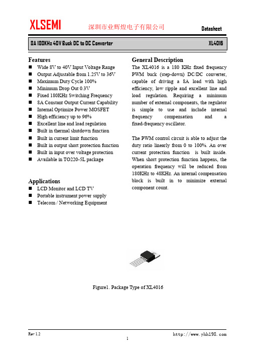
8A 180KHz 40V Buck DC to DC Converter XL4016FeaturesnWide 8V to 40V Input Voltage Range n Output Adjustable from 1.25V to 36V n Maximum Duty Cycle 100% n Minimum Drop Out 0.3Vn Fixed 180KHz Switching Frequency n 8A Constant Output Current Capability n Internal Optimize Power MOSFET n High efficiency up to 96%n Excellent line and load regulation n Built in thermal shutdown function n Built in current limit functionn Built in output short protection function n Built in input over voltage protection n Available in TO220-5L packageApplicationsn LCD Monitor and LCD TVn Portable instrument power supply n Telecom / Networking EquipmentGeneral DescriptionThe XL4016 is a 180 KHz fixed frequency PWM buck (step-down) DC/DC converter, capable of driving a 8A load with high efficiency, low ripple and excellent line and load regulation. Requiring a minimum number of external components, the regulator is simple to use and include internal frequency compensation and a fixed-frequency oscillator.The PWM control circuit is able to adjust the duty ratio linearly from 0 to 100%. An over current protection function is built inside. When short protection function happens, the operation frequency will be reduced from 180KHz to 48KHz. An internal compensation block is built in to minimize external component count.Figure1. Package Type of XL40168A 180KHz 40V Buck DC to DC ConverterXL4016Pin ConfigurationsFigure2. Pin Configuration of XL4016 (Top View) Table 1 Pin DescriptionPin Number Pin Name Description1 GND Ground Pin. Care must be taken in layout. This pin should be placed outside of the Schottky Diode to output capacitor ground path to prevent switching current spikes from inducing voltage noise into XL4016.2 FB Feedback Pin (FB). Through an external resistor divider network, FB senses the output voltage and regulates it. The feedback threshold voltage is 1.25V.3 SW Power Switch Output Pin (SW). SW is the switch node that supplies power to the output.4 VC Internal V oltage Regulator Bypass Capacity. In typical system application, The VC pin connect a 1uf capacity to VIN.5 VIN Supply V oltage Input Pin. XL4016 operates from a 8V to 40V DC voltage. Bypass Vin to GND with a suitably large capacitor to eliminate noise on the input.8A 180KHz 40V Buck DC to DC Converter XL4016 Function BlockFigure3. Function Block Diagram of XL4016Typical Application CircuitFigure4. XL4016 Typical Application Circuit (VIN=8V~40V, VOUT=5V/8A)8A 180KHz 40V Buck DC to DC Converter XL4016 Ordering InformationPart Number Marking ID Lead Free Lead Free Packing TypePackage TemperatureRangeXL4016E1 XL4016E1 TubeXLSEMI Pb-free products, as designated with “E1” suffix in the par number, are RoHS compliant.Absolute Maximum Ratings(Note1)Parameter Symbol Value Unit Input Voltage Vin -0.3 to 45 V Feedback Pin Voltage V FB-0.3 to Vin V Output Switch Pin Voltage V Output-0.3 to Vin V Power Dissipation P D Internally limited mW Thermal Resistance (TO220-5L)(Junction to Ambient, No Heatsink, Free Air)R JA30 ºC/W Operating Junction Temperature T J-40 to 125 ºC Storage Temperature T STG-65 to 150 ºC Lead Temperature (Soldering, 10 sec) T LEAD260 ºC ESD (HBM) >2000 V Note1: Stresses greater than those listed under Maximum Ratings may cause permanent damage to the device. This is a stress rating only and functional operation of the device at these or any other conditions above those indicated in the operation is not implied. Exposure to absolute maximum rating conditions for extended periods may affect reliability.8A 180KHz 40V Buck DC to DC Converter XL4016 XL4016 Electrical CharacteristicsT a = 25℃;unless otherwise specified.Symbol Parameter Test Condition Min. Typ. Max. Unit System parameters test circuit figure4VFB FeedbackV oltageVin = 8V to 40V, V out=5VIload=0.5A to 8A1.225 1.25 1.275 VEfficiency ŋVin=12V ,V out=5VIout=6A- 87 - %Efficiency ŋVin=24V ,V out=12VIout=6A- 93 - %Electrical Characteristics (DC Parameters)Vin = 12V, GND=0V, Vin & GND parallel connect a 470uf/50V capacitor; Iout=500mA, T a = 25℃; the others floating unless otherwise specified.Parameters Symbol Test Condition Min. Typ. Max. Unit Input operation voltage Vin 8 40 V Quiescent Supply Current I q V FB =Vin 2.1 5 mA Oscillator Frequency Fosc 144 180 216 KHz Output Short Frequency Fosp 48 KHz Switch Current Limit I L V FB =0 10 A Max. Duty Cycle D MAX V FB=0V 100 %Output Power PMOS Rdson V FB=0V, Vin=12V,I SW=8A40 50 mohmVin Over V oltage Protection OVP 45 V8A 180KHz 40V Buck DC to DC ConverterXL4016Typical System Application (VOUT=5V/8A)Figure5. XL4016 System Parameters Test Circuit (VIN=8V~40V, VOUT=5V/8A)50556065707580859095100Efficiency VS Load currentE f f i c i e n c y (%)Load current(A)Figure6. XL4016 System Efficiency Curve8A 180KHz 40V Buck DC to DC ConverterXL4016Typical System Application (VOUT=12V/6A)Figure7. XL4016 System Parameters Test Circuit (VIN=15V~40V, VOUT=12V/6A)0.00.51.01.52.02.53.03.54.04.55.05.56.050556065707580859095100Efficiency VS Load currentE f f i c i e n c y (%)Load current(A)Figure8. XL4016 System Efficiency Curve8A 180KHz 40V Buck DC to DC Converter XL4016Typical System Application (With Enable function)Logic level signal shutdown function can be used in typical system application with externalcomponents. When the TTL high voltage above 3.3V(referenced to ground, lower than VIN), the converter will shutdown, input current less than 3mA; when theTTL Low voltage below 0.8V(referenced to ground), the converter will turn on.L1 47uH/12AFigure9. XL4016 Typical Application Circuit with Enable Function8A 180KHz 40V Buck DC to DC Converter XL4016Package InformationTO220-5L。
贝加莱50点壁厚控制器说明书3.30

PP41型壁厚控制器使用说明书贝加莱工业自动化(上海)有限公司目录系统特性简介 (3)1系统特性介绍 (3)2控制系统各部件介绍 (4)2.1控制操作面板 (4)2.1.1 面板 42.1.2 接口 52.1.3 性能 62.1.4 安装 62.2功能按键及指示灯 (7)2.3控制器及接线 (9)2.3.1AI351 (9)2.3.2 Am351 (10)2.3.3 PP41自带输入 (10)2.3.4 PP41自带输出 (11)3画面操作说明 (12)3.1登陆画面 (12)3.2连续式型胚曲线设定画面 (12)3.2.1 操作按钮 (12)3.2.2 输入参数 (13)3.2.3 输出参数 (14)3.2.4 插入与删除设定数值点 (14)3.2.5 微调设定数值点间的曲线单元 (15)3.3储料式型胚曲线设定画面 (17)3.3.1 操作按钮 (17)3.3.2 输入参数 (18)3.3.3 输出参数 (19)3.4曲线跟踪画面 (19)3.5标记画面 (20)3.6存储画面 (20)3.7文件改名画面 (21)3.8参数存储画面 (21)3.9文件调出画面 (22)3.10监控画面 (22)3.11数据1(曲线点)画面 (22)3.12数据2画面 (23)3.13初始设定画面 (23)3.13.1 输入参数 (23)3.13.2 模式转换 (24)3.14型芯设定画面 (24)3.14.1 输入参数 (24)3.14.2 输出参数 (25)3.14.3 手动调校 (25)3.14.4 自动调校 (25)3.14.5 调校提示: (25)3.15储料设定画面 (26)3.15.1 输出参数 (26)3.15.2 手动调校 (26)3.16增益设定画面 (26)3.16.1 按钮 273.16.2 输入参数 (27)3.16.3 输出参数 (27)3.17时间设定画面 (27)3.17.1 输入参数 (27)3.17.2 输出参数 (27)3.18中英文切换画面 (28)4机器操作说明 (29)4.1开机步骤 (29)4.2系统参数设定 (29)4.2.1 初始设定 (29)4.2.2 型芯设定 (29)4.2.3 储料设定 (29)5故障处理 (30)5.1故障对应 (30)5.2干扰处理 (30)6电源 (30)7附件 (30)系统特性简介1 系统特性介绍这是一款50点型坯壁厚控制器,用来控制中空成型机型坯的壁厚。
50SQ080-G资料

元器件交易网
SENSITRON SEMICONDUCTOR
Data Sheet 2866, Rev.
Βιβλιοθήκη
:- , 5 ". - ". " =-> $!-." . " " =-> , ( 0 @
• • • d • !" • • • • • #$%& " ' " " ( )" * "" ' " )" " " ) " '+ " ," ' " " ) "!
* !" + ,-.. + ,-.. "0 1 ! ,-.. "0
" ""
"# $!
!
%&' &'&
• 221 West Industry Court ! Deer Park, NY 11729-4681 ! (631) 586-7600 FAX (631) 242-9798 • • World Wide Web Site - • E-Mail Address - sales@ •
SC50560中文资料
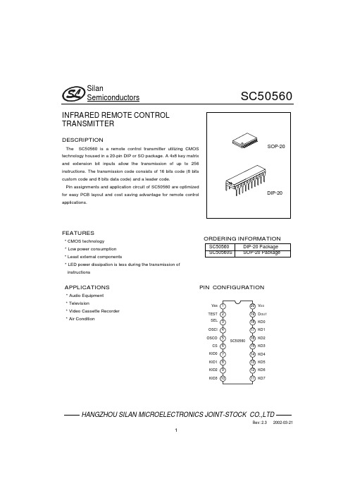
SilanSemiconductorsSC50560HANGZHOU SILAN MICROELECTRONICS JOINT-STOCK CO.,LTDRev:2.32002-03-211INFRARED REMOTE CONTROLTRANSMITTERDESCRIPTIONThe SC50560is a remote control transmitter utilizing CMOStechnology housed in a20-pin DIP or SO package.A4x8key matrixand extension bit inputs allow the transmission of up to256instructions.The transmission code consists of16bits code(8bitscustom code and8bits data code)and a leader code.Pin assignments and application circuit of SC50560are optimizedfor easy PCB layout and cost saving advantage for remote controlapplications.FEATURES*CMOS technology*Low power consumption*Least external components*LED power dissipation is less during the transmission ofinstructionsORDERING INFORMATIONSC50560SC50560SDIP-20PackageSOP-20PackageAPPLICATIONS PIN CONFIGURATION*Audio Equipment*Television*Video Cassette Recorder*Air ConditionVssTESTSELOSCIOSCOCSKIO0KO7KO6KO5KO4KO3KO2KO1KO0D OUTV DDKIO1KIO2KIO3SilanSemiconductorsSC50560HANGZHOU SILAN MICROELECTRONICS JOINT-STOCK CO.,LTDRev:2.32002-03-212BLOCKDIAGRAMKIO0KIO1KIO2KIO3VSSVDDCSOSCOOSCIDOUTSELABSOLUTE MAXIMUM RATINGS (Tamb=25°C)Characteristic Symbol ValueUnit Supply Voltage V CC-0.3~5.5VInput Voltage V IN Vss-0.3V~V DD+0.3V VOutput Voltage V OUT Vss≤Vo≤V DD VOperating Temperature Topr-20~70°CStorage Temperature Tstg-40~+125°CELECTRICAL CHARACTERISTICS(Tamb=25°C, V DD=3.0V,Vss=0,Unless otherwise specified) Parameter SymbolTestConditionsMinTyp MaxUnitSupply Voltage V DD Fosc=455KHz 2.0 3.0 4.0VOperating Current I OP Fosc=455KHz0.120.3mAStand-by Current I SBOSCO=V DD KIO0~KIO3=V DDTEST=Vss SEL=Vss0.11µAHigh level Output Current(Dout)I OH V OH=2V-1.0-13mAI OL0.5 1.2Low Level Output Current(Dout,KO0~KO7)I KO0~KO7V OL=0.9V4.55.3mAHigh Level Input Voltage(CS)(KIO0~KIO3)V IH V DD=3.0V0.7V DD V DD VLow Level Input Voltage(CS)(KIO0~KIO3)V IL V DD=3.0V00.3V DD VInput Pull-High Resistance(KIO0~KIO3)R IN V DD=3.0V557085kΩSilanSemiconductorsSC50560HANGZHOU SILAN MICROELECTRONICS JOINT-STOCK CO.,LTDRev:2.32002-03-213PIN DESCRIPTIONPin No. Pin Name Input/output Description1V SS--Negative Power Supply2TEST I Test Pin.This pin is normally connected to VSS.3SEL I Select Pin for SC50560-001/003.4OSCI I Oscillation Input Pin5OSCO O Oscillation Output Pin6CS I Code Select Pin7~10KIO0~KIO3I/O Input/Output Pins18~11KO0~KO7O Scan Output Pins19Dout O Output Pin20V DD--Positive PowerSupplyFUNCTIONAL DESCRIPTIONSC50560is capable of transmitting up to256different instructions and8bits custom codes using a16-bit PCM Code with a leader code.Furthermore,oscillation is normally stopped when there is no operating,thereby,lower power dissipation.1. TRANSMISSION CODESC50560transmission code consists of a leader code,8bits custom code(C0to C7)followed by a sync.bit and8bits data code(D0to D7)followed another sync.bit.The custom and the data codes are separated by a separator.Please refer to the diagram below:Sync.Bit Sync.BitFigure1.SC50560Transmission Code FormatOne transmission Code Word consists of a19-bit pulse(that is the leader pulse plus the16bits code)and the separator.It is transferred in a63.4ms for as long as the key is depressed.Please refer to the diagram below:SEPARATOR8BITS CUSTOM CODE8BITS DATA CODEFigure2.SC50560Detailed Code Word FormatSilanSemiconductorsSC50560HANGZHOU SILAN MICROELECTRONICS JOINT-STOCK CO.,LTDRev:2.32002-03-214LEADER CODEThe leader code is located at the beginning of the transmission code and is made up of8.4ms HIGH&4.2ms LOW pulse and is modulated in38KHz providing easy identification of the reception code head bit at the receiver.CUSTOM CODECustom Code may be selected by connection CS Input with Scan Output(KO0to KO4).An example of a custom code selection is shown in the diagram below.Custom Code101010C6C7Figure3.custom Code Selection ExampleDATA CODED0to D7of the transmission code are the data code bits.When CS Input and the Scan Output(KO5toKO7)are connected,data bits—D5to D7becomes the system extended code bits.An example of theExtended code Bits Selection is given in the diagram below:Data Code D5 D6 D7SW=OFF100SW=ON101 Figure4.Extended Code Selection2. SEPARATORThe separator demarcates the custom code and the data code.It consists of a4.2ms LOW pulse interval and can be determined at the receiver so theat any interference with other remote control system may be avoided. Please refer to Figure2.SilanSemiconductorsSC50560HANGZHOU SILAN MICROELECTRONICS JOINT-STOCK CO.,LTDRev:2.32002-03-2153. CARRIERThe carrier of the transmission signal is38KHz and one pulse width is0.52ms.Therefor,with the exception ofthe leader code,there are twenty38KHz clock in one pulse width.Please refer to the diagram below.Figure5.Transmission Signal Carrier Diagram4. KEY INPUTBy connecting the input pins–KI0to KI3and scan output pins–KO0to KO7(also known as the Standard Keys),a4x8key matrix may be formed.Likewise,a maximum of256instructions may be provided by connecting the inputCS with the scan output–KO0to KO7(also known as the Extended Keys).When two or more standard keys are pressed,the transmission output Dout is kept at LOW and no transmission code is outputted.Please refer to thetables below.DataKey InputD0 D1KI000KI110KI201KI311Data Data Scan OutputD2 D3 D4CS InputD5 D6 D7 KO0000KO51----KO1100KO6--1--KO2010KO7----1KO3110KO4001KO5101KO6011KO7111SilanSemiconductorsSC50560HANGZHOU SILAN MICROELECTRONICS JOINT-STOCK CO.,LTDRev:2.32002-03-2165. Oscillation CircuitThe oscillation circuit may be constructed by connected aceramic resonator between the OSCI and OSCO.Pleaserefer to the diagram right.When the references signal is setto455KHz the carrier can be set at38KHz.When no keyinput is pressed,the oscillation circuit is normally stopped,thereby,lower power dissipation.Figure6.Oscillation Circuit6. CODE FORMAT MODESSC50560code format comes in three modes:001,002and003.Please refer to the diagram below:SC50560 Version DescriptionMinimum Number of WordsTransmittedSC50560-001Mode A Code Format:Custom Code Bit5--C5=0,SEL is connected to V DD1word SC50560-002Mode A&B Code Formats3wordsSC50560-003Mode A Code Format:Custom Code Bit5--C5=1,When SEL is connected to Vss-----Both SC50560-001and SC50560-002make use of the same operation when the input from terminal CS andthe scan output(KO0to KO4)are connected to make the custom code selection with the exception ofthe numberof word transmitted.Please refer to the table above:MODE AThe diagram below gives us the transmission code format for Mode A.One Code Word consists of the Leader Code,8bits Custom Code followed by a sync.bit,Separator and8bits Data Code followed by another sync.bit. Please refer to the diagram below.Sync.Bit Sync.BitFigure7.Mode A Code FormatEach Code Bit may either be“0”or“1”.Please refer to the diagram below.SilanSemiconductorsSC50560HANGZHOU SILAN MICROELECTRONICS JOINT-STOCK CO.,LTDRev:2.32002-03-217Bit"0"Bit"1"Figure8.Mode A Bit“0”&“1”WaveformMODE BThe diagram below gives us the transmission code format for Mode B.Under this mode,the custom codes arenot selected,therefore the transmission code only consists of the6bits data code followed by a sync.bit.Pleaserefer to the diagram below:SYNCD0D1D2D3D4D5Data CodeFigure9.Mode B Code FormatAtransmission Code Bit may either be“0”or“1”.Please refer to the diagram below:Bit"0"Bit"1"Figure10.Mode B Bit“0”&“1”Waveform DiagramUnder Mode B,a maximum of32different instructions may be provided simply by connecting the inputs KI0toKI3with the Scan Outputs KO0to KO7,thereby constructing a4x8key matrix.When two or more keys are pressedat the same time,the transmission output Dout is set to and the no transmission occurs.Please refer to the table below.KO0 KO1 KO2 KO3 KO4 KO5 KO6 KO7 KI0 0004080C10*14*18*1C*KI1 010509*0D*11*15*19*1D*KI2 02060A*0E*12*16*1A*1E*KI3 03070B*0F*13*17*1B*1F* NOTE:*=Output of a five-word transmission code.SilanSemiconductorsSC50560HANGZHOU SILAN MICROELECTRONICS JOINT-STOCK CO.,LTDRev:2.32002-03-218APPLICATION CIRCUIT1. For 01 and 03 VersionsSettings for DataSilanSemiconductorsSC50560HANGZHOU SILAN MICROELECTRONICS JOINT-STOCK CO.,LTDRev:2.32002-03-2192. Extended CodesCustom Code SettingStandard Code Extended CodeKI0KI1KI2KI3KI0KI1KI2KI3 KO000010203KO104050607KO208090A0FKO30C0D0E0BKO410111213Not UsedKO51415161734353637KO618191A1B58605A5BKO71C1D1E1F9C8D9E9FSilanSemiconductorsSC50560HANGZHOU SILAN MICROELECTRONICS JOINT-STOCK CO.,LTDRev:2.32002-03-21103. Double Key OperationCustom Code Setting Double KeySilanSemiconductorsSC50560HANGZHOU SILAN MICROELECTRONICS JOINT-STOCK CO.,LTDRev:2.32002-03-21114. No Leader Code and Custom CodeSilanSemiconductorsSC50560HANGZHOU SILAN MICROELECTRONICS JOINT-STOCK CO.,LTDRev:2.32002-03-2112CHIP TOPOGRAPHY1716151413121110987654321201918Size:1.40x1.21mm2PAD COORDINATES (Unit:µm)No. Symbol X Y No. Symbol X Y1P1-579.10-35.5011P11579.00142.30 2P2-579.10-184.5012P12579.00291.30 3P3-579.10-333.5013P13579.00440.30 4P4-579.10-482.5014P14270.80482.50 5P5-141.60-482.5015P15121.80482.50 6P68.3-482.5016P16-27.20482.50 7P7421.60-482.5017P17-176.20482.50 8P8579.00-304.7018P18-579.10411.50 9P9579.10-155.7019P19-579.10262.50 10P10579.10-6.7020P20-579.10113.50 Note:The original point of the coordinate is the die center.SilanSemiconductorsSC50560HANGZHOU SILAN MICROELECTRONICS JOINT-STOCK CO.,LTDRev:2.32002-03-2113PCB WIRE LAYOUT SCHEMATIC:layout separated or overstriking ground line.The above IC only use to hint,not to specified.Note:*In wire layout,the power filter capacitor should near to IC.*In wire layout,should avoid power line and ground line too long.*Recommended infrared transmit unit and IC ground line should layout separated,or overstriking lines.*The emitter of triode connect1¡resistor at least.*Recommended triode use9014.SilanSemiconductorsSC50560HANGZHOU SILAN MICROELECTRONICS JOINT-STOCK CO.,LTDRev:2.32002-03-2114SilanSemiconductorsSC50560HANGZHOU SILAN MICROELECTRONICS JOINT-STOCK CO.,LTDRev:2.32002-03-2115AttachRevision HistoryData REV Description Page 2000.12.31 2.0Change name of company in page footer2002.01.04 2.1Delete“or floating“in“6.code format modes”6 2002.02.28 2.2Modify the“Pin configuration“Modify the“Application circuit”Add the“PCB wire layout schematic”Modify the“Package outline”18-111314 2002.03.21 2.3Modify the“figure3”and“figure4”4。
Ra-01SC 规格书说明书

Ra-01SC规格书版本V1.1版权©2021免责申明和版权公告本文中的信息,包括供参考的URL地址,如有变更,恕不另行通知。
文档“按现状”提供,不负任何担保责任,包括对适销性、适用于特定用途或非侵权性的任何担保,和任何提案、规格或样品在他处提到的任何担保。
本文档不负任何责任,包括使用本文档内信息产生的侵犯任何专利权行为的责任。
本文档在此未以禁止反言或其他方式授予任何知识产权使用许可,不管是明示许可还是暗示许可。
文中所得测试数据均为安信可实验室测试所得,实际结果可能略有差异。
文中提到的所有商标名称、商标和注册商标均属其各自所有者的财产,特此声明。
最终解释权归深圳市安信可科技有限公司所有。
注意由于产品版本升级或其他原因,本手册内容有可能变更。
深圳市安信可科技有限公司保留在没有任何通知或者提示的情况下对本手册的内容进行修改的权利。
本手册仅作为使用指导,深圳市安信可科技有限公司尽全力在本手册中提供准确的信息,但是深圳市安信可科技有限公司并不确保手册内容完全没有错误,本手册中的所有陈述、信息和建议也不构成任何明示或暗示的担保。
文件制定/修订/废止履历表版本日期制定/修订内容制定核准V1.02021.3.15首版邹胜锌关宁V1.12021.3.31更新邹胜锌关宁目录1产品概述 (5)1.1特性 (5)1.2主要参数 (6)2电气参数 (7)2.1电气特性 (7)2.2数字端口特性 (7)2.3SPI接口特性 (8)3外观尺寸 (9)4管脚定义 (10)5原理图 (11)6设计指导 (12)6.1应用电路 (12)6.2推荐模组封装设计尺寸 (12)6.3天线的安装 (13)6.4供电 (13)6.5GPIO口的使用 (14)6.6软件的编写 (14)7常见问题 (15)7.1影响传输距离因素 (15)7.2模块使用注意事项 (15)7.3对模块造成干扰的因素 (15)8回流焊曲线图 (16)9相关型号及天线指南 (17)9.1相关型号 (17)9.2天线推荐 (17)10包装信息 (18)11联系我们 (18)1产品概述安信可LoRa系列模块Ra-01SC由深圳市安信可科技有限公司设计开发的。
SMC6400B使用手册200942710010534[1]
![SMC6400B使用手册200942710010534[1]](https://img.taocdn.com/s3/m/7b649ce7524de518964b7dc1.png)
本手册版权归深圳市雷泰控制技术有限公司所有,未经雷泰 公司书面许可,任何人不得翻印、翻译和抄袭本手册中的任何内 容。 本手册中的信息资料仅供参考。 由于改进设计和功能等原因, 雷泰公司保留对本资料的最终解释权。内容如有更改,恕不另行 通知。
调试机器要注意安全!用户必须在机器中设计有效的安全保护装置,在 软件中加入出错处理程序。否则所造成的损失,雷泰公司没有义务或责任对 此负责。
SC400控制系统用户说明书
Version 1.4
深圳 市雷泰 控制技 术有 限公司
S HE NZ HE N LE AD TE CH C ON TR OL T EC HN OL OG Y CO ., L TD
-1-
©Copyright 2007 Leadtech Control Technology Co.,Ltd. All Rig h ts Re se r ve d . 版 权 说 明2 1.3 1.4 第二章 2.1
录
概述................................................................................................................................ - 1 产品概述......................................................................................................................... - 1 技术特性..................................................................................................
2SC5010中文资料(nec)中文数据手册「EasyDatasheet - 矽搜」
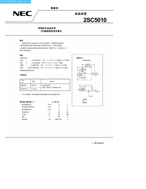
µA V = 5 V, I = 0
0.1
µA V = 1 V, I = 0
75
150
V = 3 V, I = 10 mA* 1
f C |S |2
12.0
0.4
7.0
8.5
GHz V = 3 V, I = 10毫安,F = 2千兆赫
0.7
pF V = 3 V, I = 0,F = 1兆赫* 2
dB V = 3 V, I = 10毫安,F = 2千兆赫
S
MAG
ANG
100.00
.855
–14.2
200.00
.787
–28.4
300.00
.715
–41.9
400.00
.631
–54.9
500.00
.561
–66.5
600.00
.495
–77.0
700.00
.434
–86.4
800.00
.387
–95.8
900.00
.346
–104.1
1000.00
特征
•使用低电压.
•高氟 T :12.0 GHzTYP. (用V CE = 3 V, I C = 10毫安,F = 2千兆赫)
•低C re :0.4 pF典型值. (用V CE = 3 V, I E = 0,F = 1兆赫)
•低NF •高| S
1.5 dB典型值. (用V CE = 3 V, I C = 3毫安,F = 2千兆赫) 21e|2 8.5 dB典型值. (用V CE = 3 V, I C = 10毫安,F = 2千兆赫)
0
0.5
1.0
V - 基地发射极电压 - V
NCP1608BDR2G;NCP1608BOOSTGEVB;中文规格书,Datasheet资料

Rsense
RZCD
ZCD
VControl
VDD Icharge
VEAH Clamp
Add Ct Offset
PWM − +
POK
LEB +
+ OCP −
VILIM
+
+
−
VZCD(ARM)
+ +−
VZCD(TRIG)
ZCD Clamp
DRV
SQ RQ Reset Off Timer mVDD
Demag
Pin Name
Function
1
FB The FB pin is the inverting input of the internal error amplifier. A resistor divider scales the output voltage to VREF to main-
tain regulation. The feedback voltage is used for overvoltage and undervoltage protections. The controller is disabled
SQ RQ
SQ RQ SQ RQ
VCC UVLO
SQ
RQ
VDDGD
mVDD
POK
DRV GND
All SR Latches are Reset Dominant
Figure 2. Block Diagram
/
2
NCP1608
Table 1. PIN FUNCTION DESCRIPTION
RZCD
+ Cin
2SA1215中文资料(sanken)中文数据手册「EasyDatasheet - 矽搜」
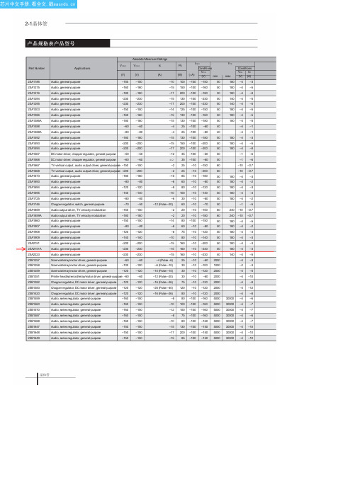
Chopper regulator, DC motor driver, general-purpose –120
Chopper regulator, DC motor driver, general-purpose –120
Audio, seriesregulator, general-purpose
–100 –160 5000
–100 –160 5000
–100 –160 5000
–100 –160 5000
–100 –160 5000
–100 –150 5000
–100 –150 5000
–100 –150 5000
hFE max
Conditions VCE Ic (V) (A)
180 –4 –3
–150
Audio output driver, TV velocity modulation
–180
Audio, general-purpose
–150
Audio, general-purpose
–80
Audio, general-purpose
–120
Audio, general-purpose
–80
Audio, general-purpose
–120
Audio, general-purpose
–140
Audio, general-purpose
–80
Chopper regulator, switch, general-purpose
–70
Audio output driver, TV velocity modulation
VCBO Applications
(V)
原材料物料表-量产-3
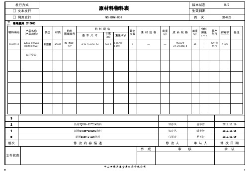
长度 (mm)
重量(Kg)
锯切 支数
素 材 规 格
单重 (g)
成 品 规 格
单重 (g)
物料 用量 (个)
1
量产 年月
2011年 11月
损耗率
备注
31005015
铝圆管
A5052
269.8 0.057±0.001
1
—
—
Φ26xΦ 24.24x268.8
48
5.00%
以下空白
3 2 1 0
新增SJC66-02722A物料 新增SJC66-03089A物料 新增SGBN714200物料 邹春凤 邹春凤 邝丽青 潘华智 潘华智 罗英好 2011.11.10 2011.10.06 2011.08.09
发行方式 □ 文本发行 □ 网页发行
客户: 珠海盈贝(31005) 物料编码 产品名称 (产品简称)
SJC66-02722A (简称:02722)
原材料物料表
WS-BOM-001
版本状态 生效日期 页 次
B/2
第49页
类型
材质
购料 图纸编号
WS-图SC179
购 料 规 格 基 本 尺 寸
Φ26.2xΦ24.24
版次
修 改 内 容 描 述 作 成
修 改 人 审 核
承 认 人
修 改 日 期 承 认
文件状态
中山市维美适金属制品有限公司
3 2 1 0 版次
新增302HN25010-03(C)物料表 邝丽青 潘华智 2011.09.03
修 改 内 容 描 述 作成
修改人 审 核
承认人
修 改 日 期 承 认
文件状态
中山市维美适金属制品有限公司
SR160肖特基二极管
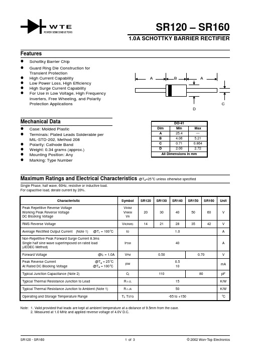
SR120 – SR1601.0A SCHOTTKY BARRIER RECTIFIERSingle Phase, half wave, 60Hz, resistive or inductive load.For capacitive load, derate current by 20%.Characteristic Symbol SR120 SR130 SR140 SR150 SR160 UnitPeak Repetitive Reverse VoltageWorking Peak Reverse Voltage DC Blocking Voltage V RRMV RWM V R 2030405060V RMS Reverse VoltageV R(RMS)1421283542V Average Rectified Output Current (Note 1) @T L = 100°C I O 1.0A Non-Repetitive Peak Forward Surge Current 8.3ms Single half sine-wave superimposed on rated load (JEDEC Method)I FSM 40A Forward Voltage @I F = 1.0A V FM 0.500.70V Peak Reverse Current @T A = 25°C At Rated DC Blocking Voltage @T A = 100°C I RM 0.510mA Typical Junction Capacitance (Note 2)C j 11080pF Typical Thermal Resistance Junction to LeadR JL 15K/W Typical Thermal Resistance Junction to Ambient (Note 1)R JA 50K/W Operating and Storage Temperature RangeT j , T STG-65 to +150°CNote: 1. Valid provided that leads are kept at ambient temperature at a distance of 9.5mm from the case.2. Measured at 1.0 MHz and applied reverse voltage of 4.0V D.C.W T EWER SEMICONDUCTORS10203040110100I ,P E A K F O R W A R D S U R G E C U R R E N T (A )F S M NUMBER OF CYCLES AT 60HzFig.3Max Non-Repetitive Peak Fwd Surge Current1010010000.1110100C ,J U N C T I O N C A P A C I T A N C E (p F )j V ,REVERSE VOLTAGE (V)Fig.4Typical Junction CapacitanceR020406080100120140I ,I N S T A N T A N E O U S R E V E R S E C U R R E N T (m A )R PERCENT OF RATED PEAK REVERSE VOLTAGE (%)Fig.5Typical Reverse Characteristics100101.00.10.010.0010.11.010I ,I N S T A N T A N E O U S F O R W A R D C U R R E N T (A )F V ,INSTANTANEOUS FORWARD VOLTAGE (V)Fig.2Typical Forward CharacteristicsF 200.50.10.91.31.72.10.51.0255075100125150I A V E R A G E F O R W A R D C U RR E N T (A )(O ),T ,LEAD TEMPERATURE (C)Fig.1Forward Current Derating CurveL °ORDERING INFORMATIONProduct No.!Package TypeShipping QuantitySR120-T3DO-415000/Tape & Reel SR120-TB DO-415000/Tape & Box SR120DO-411000 Units/Box SR130-T3DO-415000/Tape & Reel SR130-TB DO-415000/Tape & Box SR130DO-411000 Units/Box SR140-T3DO-415000/Tape & Reel SR140-TB DO-415000/Tape & Box SR140DO-411000 Units/Box SR150-T3DO-415000/Tape & Reel SR150-TB DO-415000/Tape & Box SR150DO-411000 Units/Box SR160-T3DO-415000/Tape & Reel SR160-TB DO-415000/Tape & Box SR160DO-411000 Units/BoxProducts listed in bold are WTE Preferred devices.!T3 suffix refers to a 13” reel. TB suffix refers to Ammo Pack.Shipping quantity given is for minimum packing quantity only. For minimum order quantity, please consult the Sales Department.Won-Top Electronics Co., Ltd (WTE) has checked all information carefully and believes it to be correct and accurate. However, WTE cannot assume any responsibility for inaccuracies. Furthermore, this information does not give the purchaser of semiconductor devices any license under patent rights to manufacturer. WTE reserves the right to change any or all information herein without further notice.WARNING : DO NOT USE IN LIFE SUPPORT EQUIPMENT. WTE power semiconductor products are not authorized for use as critical components in life support devices or systems without the express written approval.We power your everyday.Won-Top Electronics Co., Ltd.No. 44 Yu Kang North 3rd Road, Chine Chen Dist., Kaohsiung, Taiwan Phone: 886-7-822-5408 or 886-7-822-5410Fax: 886-7-822-5417Email: sales@Internet: 。
0603-T0.4白色贴片式发光二极管产品名称:XL-1608UWC-04说明书

产品承认书产品名称:0603-T0.4白色贴片式发光二极管产品型号:XL-1608UWC-04客户名称:客户料号:承认日期:深圳市成兴光电子科技有限公司制定审核核准客户承认栏确认审核核准一、产品描述:●外观尺寸(L/W/H): 1.6x0.8x0.4mm●颜色:高亮度白色●胶体:黄色胶体●EIA规范标准包装●环保产品,符合ROHS要求●适用于自动贴片机●适用于红外线回流焊制程二、外形尺寸及建议焊盘尺寸:C athode A nodeGreen mark建议焊盘尺寸备注:1.单位:毫米(mm)2.公差:如无特别标注则为±0.10mm三、建议焊接温度曲线:有铅制程无铅制程四、最大绝对额定值(Ta=25℃):参数符号最大额定值单位消耗功率Pd80mW最大脉冲电流(1/10占空比,0.1ms脉宽)I FP100mA正向直流工作电流I F25mA 反向电压V R5V 工作环境温度Topr-30°C~+85°C存储环境温度Tstg-40°C~+90°C焊接条件Tsol 回流焊:260°C,10s 手动焊:300°C,3s五、光电参数(Ta=25℃):参数符号最小值代表值最大值单位测试条件光强IV 75---130mcd IF =5mA 半光强视角2θ1/2---120---deg IF =5mA 正向电压VF 2.6--- 3.0V IF =5mA 反向电流IR------1uAVR=5V亮度分档:代码最小值最大值单位测试条件M67590mcdIF=5mAM790110M8110130电压分档:代码最小值最大值单位测试条件W10 2.6 2.7VIF=5mAW11 2.7 2.8W12 2.8 2.9W132.93.0色温分档:代码最小值最大值单位测试条件C11370016000KIF=5mAB11600019000A11900024000X12300033000六、光电参数代表值特征曲线:注:如无另外注明,测试环境温度为25+3 Cφ6七、标签标识:CAT:光强(mcd)HUE:XYREF:电压(V)误差范围a.Luminous Intensity:±15%b.HUE:±0.003c.Forward Voltage:±0.1V八、包装载带与圆盘尺寸:φ13.0AA A-A剖面图U ser Feed D irection备注:1.尺寸单位为毫米(mm);2.尺寸公差如无标注,为±0.15mm;九、圆盘及载带卷出方向及空穴规格:尾端空壳载带的组合开始端空壳载带的组合盖带与空壳载带的组合十、内包装及外包装:内标签圆盘干燥剂防潮防静电袋5cartons/box外标签抽真空、热封10bags/carton至少160mm盖带和装有零件部分至少160mm盖带和至少160mm独立盖带或十一、信赖性实验:测试项目测试条件测试次数参考标准失效判定标准失效LED数量(PCS)1.回流焊最高温度=260℃,10秒,2次回流焊;JEITA防潮等级-ED-4701﹟10/222.回流焊之前存储条件:30℃,相对湿度300.301=70%,168H;焊接信赖性(无铅回流焊)回流焊最高温度=245±5℃,5秒(无铅回流焊)-JEITAED-4701303303A﹟20/22冷热循环-40℃30分钟~25℃5分钟~100℃30分钟~25℃5分钟300个循环JESD22-A104﹟10/22冷热冲击-35℃15分钟转换时间3分钟85℃15分钟300个循环JESD22-A106﹟10/22高温存储Ta=100℃1000小时JESD22-A103﹟10/22低温存储Ta=-40℃1000小时JESD22-A119﹟10/22常温老化Ta=25℃IF=20mA1000小时JESD22-A108﹟10/22(2)失效标准标准﹟项目测试条件失效标准﹟1正向电压(V F)I F=20mA>U.S.L*1.1光强(IV)I F=20mA<L.S.L*0.7反向电流(I R)V R=5V>U.S.L*2.0﹟2焊接可靠性/锡膏覆盖焊盘比例小于95%★U.S.L:规格上限L.S.L:规格下限十二、使用注意事项:◆使用:1.过高的温度会影响LED的亮度以及其他性能,所以为使LED有较好的性能表现,应将LED远离热源。
ER1603FCT中文资料(Won-Top Electronics)中文数据手册「EasyDatasheet - 矽搜」

标识信息
WTE
ER160xFCT WTE =制造商标志 ER160xFCT =设备号 x = 0,1,1A,2,3,4或6个 极性 =对人体标示
封装信息
BULK
管尺寸 长×宽×高(mm) 数量 内箱尺寸 长×宽×高(mm) 数量 外箱尺寸 长×宽×高(mm) 数量 约.总重量
(PCS) 50
(PCS) 2,000
6-32六角头螺丝
平焊盘圈
锥形焊盘圈应该用于正确力施加到所述设 备.螺钉不应收紧与任何类型空气被迫扭 矩或器材可能导致裂纹器件封装.
整流器 散热器 锥形焊盘圈
导热硅脂或接口散热焊盘一层将是散热相当 有帮助.
6-32六角螺母
ER1600FCT – ER1606FCT
3 of 4
芯片中文手册,看全文,戳
芯片中文手册,看全文,戳
ER1600FCT – ER1606FCT
16A玻璃钝化双超快速整流器 特征
玻璃钝化模具结构 超快速切换 低正向压降 低反向漏电流 高浪涌电流能力 塑料材料具有UL可燃性 分类94V-O
Pb
B C G
PIN1 2 3
A
D
机械数据
案例:ITO-220,全模制塑料 终端:每焊镀信息 MIL-STD-202,方法208 极性:见图 重量:2.24克(约) 安装位置:任意 安装扭矩:11.5厘米千克(10磅)最大. 无铅:对于符合 RoHS /无铅版本 , 新增 "-LF"后缀型号 ,见第 4页
循环次数在60Hz 图. 3最大不重复浪涌电流
10 10 100 0.1 1.0 VR,反向电压(V) 图. 4典型结电容
t +0.5A
10
100
- 1、下载文档前请自行甄别文档内容的完整性,平台不提供额外的编辑、内容补充、找答案等附加服务。
- 2、"仅部分预览"的文档,不可在线预览部分如存在完整性等问题,可反馈申请退款(可完整预览的文档不适用该条件!)。
- 3、如文档侵犯您的权益,请联系客服反馈,我们会尽快为您处理(人工客服工作时间:9:00-18:30)。
MAXIMUM RATINGS AND ELECTRICAL CHARACTERISTICS
Rating at 25℃ ambient temperature unless otherwise specified. Resistive or inductive load 60Hz. For capacitive load, derate current by 20%
10
10
1.0
T J=25°C
1.0
0.1
0.1
0.01 0 20 40 60 80 100 120 140
0.01
0.4
0.6
0.8
1.0
1.2
1.4
1.6
INSTANTANEOUS FORWARD VOLTAGE,VOLTS
PERCENT OF RATED PEAK REVERSE VOLTAGE
MSD0905018A
Page 2
/
分销商库存信息:
COMCHIP SC50VB160-G
Glass Passivated 3 Phase Bridge Rectifiers
SC50VB160-G
"-G" : RoHS Device
REVERSE VOLTAGE - 1600Volts FORWARD CURRENT - 50Amperes SCVB
1.181 MAX (30.0) .252(6.4) .213(5.4) .079(2.0) .047(1.2) .354(9.0) .315(8.0) R1.75 1.417 MAX (36.0) .295(7.5) .256(6.5) .374(9.5) .334(8.5) .374(9.5) .334(8.5) .146(3.7)*45°
CHARACTERISTICS
Maximum Recurrent Peak Reverse Voltage Maximum RMS Bridge Input Voltage Maximum Average Forward Rectified Output Current @ TC=55℃ Peak Forward Surge Current 8.3ms Single Half Sine-Wave Super Imposed on Rated Load Current Squared time (1ms<t<10ms) Dielectric Strength Mounting Torque Maximum Forward Voltage Drop Per Element at 17.5A Peak Maximum Reverse Current at Rated DC Blocking Voltage Per Element Tyical Thermal Resistance (Note1) Operating Temperature Range Storage Temperature Range NOTES: 1.Thermal Resistance Junction to case. @ TA=25℃
FEATURES
- Surge overload -500 amperes peak - Low forward voltage drop - Mounting position :Any
- W eight: 37g
.555(14.1) .516(13.1)
.492 (12.5) .516 (13.1) 1.417 MAX (36.0)
+ ~ ~ ~
.504 (Βιβλιοθήκη 2.8).256(6.50) .244(6.20)
.555(14.1) .516(13.1)
-
.035(0.9) .028(0.7)
.295(7.5) .256(6.5)
.504 (12.8)
.138(3.5)
Dimensions in inches and (milimeters)
150
FIG.3-TYPICAL FORWARD CHARACTERISTICS 100 INSTANTANEOUS FORWARD CURRENT ,(A) INSTANTANEOUS REVERSE CURRENT, MICROAMPERES 100
FIG.4-TYPICAL REVERSE CHARACTERISTICS
PULSE WIDTH 8.3ms SINGLE HALF-SINE -WAVE (JEDEC METHOD)
FIG.2- DERATING CURVE OUTPUT RECTIFIED CURRENT 50 WITH HEATSINK 40
30
20
10 0 50 100 CASE TEMPERATURE,°C
SYMBOL VRRM VRMS I(AV)
SC50VB160 1600 1120 50
UNIT V V A
IFSM I2t Vdis TOR VF IR RθJC TJ TSTG
500 500 2000 0.8 1.1 100 Max: 0.7 -55 to +150 -55 to +150
A A2S V N.m V μA ℃/W ℃ ℃
MSD0905018A /
Page 1
Glass Passivated 3 Phase Bridge Rectifiers
RATINGS AND CHARACTERISTIC CURVES SC50VB160-G
FIG.1-MAXMUN FORWARD SURGE CURRENT 500 PEAK FORWARD SURGE CURRENT , AMPERES AVERAGE FORWARD OUTPUT CURRENT , AMPERES 450 400 350 300 250 200 150 100 50 0 1 10 NUMBER OF CYCLES AT 60Hz 100
