Option Switch常用开关
Knob-type Selector Switch A22S W 推钮开关手册说明书
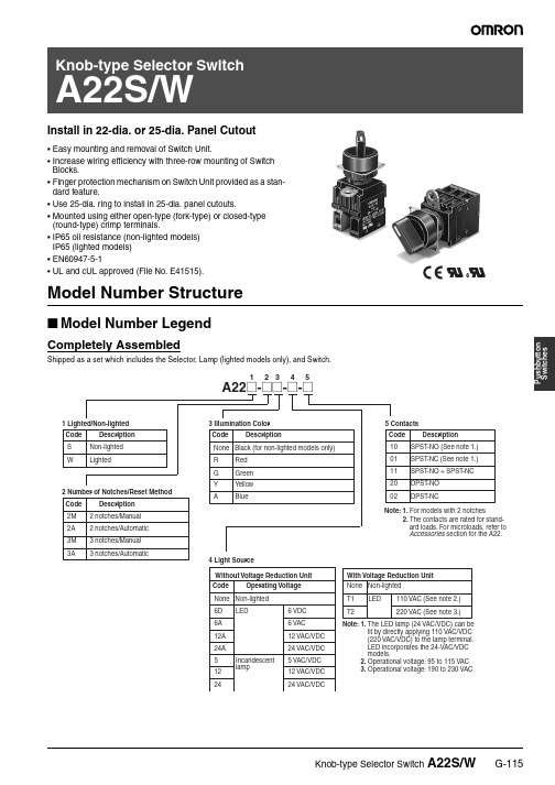
P u s h b u t t o n S w i t c h e sInstall in 22-dia. or 25-dia. Panel Cutout•Easy mounting and removal of Switch Unit.•Increase wiring efficiency with three-row mounting of Switch Blocks.•Finger protection mechanism on Switch Unit provided as a stan-dard feature.•Use 25-dia. ring to install in 25-dia. panel cutouts.•Mounted using either open-type (fork-type) or closed-type (round-type) crimp terminals.•IP65 oil resistance (non-lighted models)IP65 (lighted models)•EN60947-5-1•UL and cUL approved (File No. E41515).Model Number Structure■Model Number LegendCompletely AssembledShipped as a set which includes the Selector, Lamp (lighted models only), and Switch.SubassembledThe Selector, Lamp, or Switch can be ordered separately. Use them in combination for models that are not available as assembled Units. These can also be used as inventory for maintenance parts.1. Selector2. Lamp3. Switch (General-purpose Load)P u s h b u t t o n S w i t c h e sOrdering Information■List of ModelsOrdering as a SetNon-lightedKnob-type Selector Switch A22SLighted (Without Voltage Reduction Unit) Unit)A22WP u s h b u t t o n S w i t c h e sLighted (With Voltage Reduction Unit)Note:When ordering, specify the symbol that indicates color of the Selector in the @ of the model number.A22W(without Voltage Reduction Unit)AppearanceKnob-type Selector Switch A22WLED voltage-reduction lighting(with Voltage Reduction Unit)Ordering IndividuallySwitch (without Voltage Reduction Unit)LampLampLED LEDIncandescentlampP u s h b u t t o n S w i t c h e sSelectorsNon-lighted (Color: Only Black is Available)LightedNote:Either incandescent lamps or LED lamps can be used with theabove models.A22S-2M A22S-2A A22S-3M A22S-3A A22S-3AM A22S-3MAA22S-C2M A22S-C2A A22S-C3M A22S-C3A A22S-C3AM A22S-C3MAStandard lever IP65 (oil-resistant)A22W-2MR A22W-2MG A22W-2MY A22W-2MA A22W-2AR A22W-2AG A22W-2AY A22W-2AA A22W-3MR A22W-3MG A22W-3MY A22W-3MA A22W-3AR A22W-3AG A22W-3AY A22W-3AA A22W-3AMRLampsLED LampNote:1.For voltage-reduction lighting, use the A22-24A @.ed when the Selector color is yellow or white.Incandescent LampSwitches (General-purpose Load)Non-lightedLightedNote:For voltage-reduction lighting, use the A22-24A @.Operating voltage6 V12 V24 V24 V Super-brightAppearanceAC/DCLED lightModelDCRed A22-6DR ---------GreenA22-6DG ---------Y ellow (See note 2.)A22-6DY ---------BlueA22-6DA ---------ACRed A22-6AR ---------GreenA22-6AG ---------Y ellow (See note 2.)A22-6AY ---------BlueA22-6AA ---------AC and DCRed ---A22-12ARA22-24AR A22-24ASR Green---A22-12AG A22-24AG A22-24ASG Y ellow (See note 2.)---A22-12AY A22-24AY A22-24ASY Blue---A22-12AAA22-24AAA22-24ASAOperating voltage5 VAC/VDC12 VAC/VDC24 VAC/VDC100 VAC/VDC A22-5A22-12A22-24A22-H1ContactsModelAutomatic SPST -NO A22-10M SPST -NC A22-01M SPST -NO + SPST -NC A22-11MDPST -NO A22-20M DPST -NCA22-02MSwitch operationSwitch operationContactsVoltage-reduction circuitWith Voltage Reduction UnitAutomatic SPST -NO A22L-10M A22L-10M-T1A22L-10M-T2SPST -NCA22L-01M A22L-01M-T1A22L-01M-T2SPST -NO + SPST -NC A22L-11M A22L-11M-T1A22L-11M-T2DPST -NO A22L-20M A22L-20M-T1A22L-20M-T2DPST -NCA22L-02MA22L-02M-T1A22L-02M-T2Without Voltage Reduction Unit110 VAC 220 VACP u s h b u t t o n S w i t c h e s■Accessories (Order Separately)The A22S/W uses the same accessories as the A22. Refer to the relevant information in the section for the A22.SpecificationsWith the exception of the following items, the specifications are the same as for the A22. Refer to the relevant information in the Specifications section for the A22.■Operation Angle■Contacts2-notch Type3-notch TypeTwo notchesThree notches2. FP: Free PositionNote: 1. The angle used for automatic resetis shown in parentheses.NomenclatureDimensionsNote:All units are in millimeters unless otherwise indicated.■Knob-type Selector Switch (Lighted/Non-lighted)Lamp•Switch••Selector••A22S/A22W30 dia.A22S-C30 dia.Knob-type Selector Switch A22S/WG-125P u s h b u t t o n S w i t c h e s■Accessories (Common to A22, A22S/W, A22K, M22, and A22E)The A22S/W uses the same accessories as the A22. Refer to the relevant information in the corresponding section for the A22.■Terminal Arrangement (Bottom View)■Terminal ConnectionNote:The above terminal connection diagrams are examples forSPST -NO + SPST -NC.■Panel Cutouts (Top View)Note:1.When applying coating such as paint to the panel, the dimensions should be those after the application of coating.Lock Ring is provided as a standard item.2.Recommended panel thickness: 1 to 5 mm.e an A22Z-R25 Ring when mounting to a panel with 25-mm holes.InstallationThe A22S/W uses the same installation method as the A22. Refer to the relevant information in the Installation section for the A22.PrecautionsThe precautions for the A22S/W are the same as those for the A22. Refer to the relevant information in the Precautions section for the A22 and the Technical Information for Pushbutton Switches (Cat. No. A143).Switch BlocksM3.5 screwLamp socketSwitch BlocksTypeConnection diagramNon-lightedLighted without Voltage Reduction UnitLighted with Voltage Reduction UnitBottom viewBottom viewBottom view22.3+0.4 dia.025+0.5 dia.G-126Knob-type Selector Switch A22S/WIn the interest of product improvement, specifications are subject to change without notice.ALL DIMENSIONS SHOWN ARE IN MILLIMETERS.To convert millimeters into inches, multiply by 0.03937. T o convert grams into ounces, multiply by 0.03527.Cat. No. A129-E1-02。
switch语句的使用方法

switch语句的使用方法switch语句是一种常用的条件语句,用于根据不同的条件执行不同的代码块。
它提供了一种简洁的方式来处理多个选项。
switch语句的使用方法如下:1. switch语句由关键字switch开头,后面的括号内是待判断的表达式。
表达式的类型可以是整型、字符型、枚举型或字符串型。
2. switch语句中的每个case都代表一种可能的情况。
当表达式的值与某个case的值相等时,将执行该case后的代码块。
3. 每个case后面都需要跟着一个冒号“:”,用于标识该case的结束。
4. 如果表达式的值与任何一个case的值都不相等,那么将执行default后的代码块。
default语句可以放在switch语句的任意位置,但通常放在最后。
5. 在case的代码块中,可以包含一组语句。
在执行完这组语句后,将跳出switch语句。
下面是一个使用switch语句的示例:```int day = 1;String dayName = "";switch (day) {case 1:dayName = "Monday";break;case 2:dayName = "Tuesday";break;case 3:dayName = "Wednesday";break;case 4:dayName = "Thursday";break;case 5:dayName = "Friday";break;default:dayName = "Invalid day";break;}System.out.println(dayName);```在这个示例中,我们根据变量day的值判断今天是星期几,并将对应的星期几名称保存在变量dayName中。
最后,我们输出变量dayName的值。
switch的用法和例句

switch的用法和例句一、了解Switch的基本概念及用法Switch是一个常见的编程语句,用于在多个选项之间进行选择与判断。
它可以根据变量或表达式的不同值执行不同的代码块。
在这一段中,我们将详细介绍Switch语句的基本概念和使用方法,并给出适用于各种场景的实际例句。
1.1 Switch语句的语法结构Switch语句通常由关键字"switch"开头,后面紧跟着要被判断的变量或表达式,然后是一个或多个“case”分支和一个可选的“default”分支。
下面是一般情况下Switch语句的基本语法结构:```switch (expression){case value1:// 执行代码块1break;case value2:// 执行代码块2break;...default:// 执行默认代码块}```其中expression代表需要进行判断的表达式或变量,value1和value2为可能取得值,在匹配到相应值时执行相应代码块,break关键字用于结束当前分支并跳出switch语句。
若所有分支都没有匹配到,则会执行default分支中定义的代码块(default部分可省略)。
1.2 Switch语句与If-else语句区别Switch与If-else都可用于对条件进行判断,但二者在特定场景下有着不同的适用性。
Switch适合用于多个固定值的判断,If-else适合用于更复杂的条件判断和范围判断。
Switch语句比If语句更加简洁明了,特别是当存在大量固定值的情况下。
然而,Switch不能处理浮点数或字符串类型的变量,这时候If-else可能是更好的选择。
二、Switch语句在实际应用中的例子2.1 判断星期几并执行相应操作考虑一个简单实际例子:根据输入的数字(1到7),输出对应星期几的信息。
我们可以使用Switch语句来实现。
```python# Python代码num = int(input("请输入数字(1到7):"))week = ""switch (num):week = "星期一" break;case 2:week = "星期二" break;case 3:week = "星期三" break;case 4:week = "星期四" break;case 5:week = "星期五" break;case 6:week = "星期六" break;case 7:week = "星期日" break;print("无效输入")```上述代码根据输入数字给变量”week“赋予不同字符串值,输出对应的星期几。
switch的用法

switch的用法Switch是一种条件控制语句,用于根据不同条件执行不同的代码块。
它可以替代传统的if-else语句,简化代码结构,提高可读性和维护性。
在本文中,我将详细介绍switch语句的用法以及它的一些特性。
1.基本语法```C++case constant1:// code blockbreak;case constant2:// code blockbreak;...default:// code block```其中,expression是需要进行比较的表达式,常被称为“开关”。
case后面跟着一个常量值,用于匹配开关的值。
如果开关的值与一些case的常量值相等,则执行相应的代码块。
代码块可以是一条或多条语句,用花括号{}包围。
2. case语句每个case语句都表示一个可能的匹配条件。
如果开关的值与一些case的常量值相等,则执行相应的代码块。
代码块执行完毕后,程序将跳出switch语句,除非遇到break语句。
```C++int num = 3;case 1:cout << "Number is 1" << endl;break;case 2:cout << "Number is 2" << endl;break;case 3:cout << "Number is 3" << endl;break;default:cout << "Number is not 1, 2 or 3" << endl;```在这个例子中,num的值为3,因此与case 3匹配。
当程序执行到case 3时,将输出"Number is 3"。
由于存在break语句,程序将跳出switch语句,不会继续执行后续的case语句。
蜂巢SWITCH限位开关说明说明书

Limitless leadership. Available with a variety of actuators, electrical specifications, terminations, circuitries and sealing ratings, Honeywell’s MICRO SWITCH limit switches offer superior flexibility and performance. These precision snap-action switches — sealed in rugged housings — are used to detect presence or absence in areas where physical contact is allowed.And Honeywell delivers all the benefits your applications demand:• Reliability, repeatability, accuracy• Impressive breadth of product offerings • Tested-tough, for industrial machinery• Supreme performance, through superior application understanding• Withstanding shock, vibration, washdowns and outdoor environmentsFEATURESLIMIT SWITCHES GLA Series.Features: Metal housings for rugged applications • Galvanically isolated contacts for controlling separatecircuits • Wide variety of actuators and circuitry options for increased flexibility • International conduit sizes available for global applications • Direct-acting NC contacts designed to ensure opening when actuated • 2NO version available • Gold contacts optional for low-energy switching • EN50041 mounting pattern Benefits: Specifically designed for world-wide applications and are supported by Honeywell global resources for sale and after sale service. Applicationsinclude machine tools, material handling equipment, packaging machinery, textile machinery, construction machinery and equipment, vehicles and lift trucks.GLS Miniature (GLD, GLC, GLE) Series.Features: GLC metal housings or GLD plastic housings for design versatility (metal = better sealing, unaffected by UV light) • Galvanically isolated contacts for controlling two separate circuits • Direct-acting NC contacts deignedMICRO SWITCHLimit Switches Line Guidecontinued on page 5to ensure opening when actuated • Gold contacts optional for low-energy switching • 2NO version available • Wide variety of actuators and circuitry options for increased flexibility • International conduit sizes available for global applications • EN50047 mounting patternBenefits: Specifically designed for world-wide applications and are supported by Honeywell global resources for sale and after sale service. Applicationsinclude machine tools, material handling equipment, packaging machinery, textile machinery, construction machinery and equipment, vehicles and lift trucks.NGC Series.Features: SPDT or DPDT configurable circuitry • Snap-action, positive-break contacts • Metal or plastic housing • Pre-leaded cable and M12 connector options • Side exit (standard) and bottom exit connection options • Variety of heads and actuator leversBenefits: Can be configured more than 380,000 ways, carries global approvals, and sealed to IP67 for potential use in indoor and outdoor applications.Applications include boom position detection, elevators and escalators, machine tools, mobile light towers, packaging equipment, rail doors, and scissor liftsSZL-VL-S Series.Features: Silver-alloy contacts standard • Stainless steel levers with either steel and nylon rollers • Variety of actuators • Positive-opening contacts (plunger version only)Benefits: Designed for applications of small mounting space. Applicationsinclude scissor/boom position detection, vehicle accessibility lifts, escalators/motorized walkways, machine tools, mobile light towers, packaging equipment, conveyor equipment,overhead doors, agriculture equipmentSZL-VL-S2 MICRO SWITCH Limit Switches Line GuideMICRO SWITCH Limit Switches.Application-proven limit switches for any need:General Purpose switches meet IEC standards for worldwide acceptance — for injection molding, PLC interface, machine tooling, elevators and escalators, gaming, packaging and textile, food and beverage, industrial doors, scissor and platform lifts and electronic assembly.Heavy-duty switches offer a rugged, die-cast body — epoxy-coated — with multiple mounting and actuatoroptions. Low- and high-temp construction and factory-sealed, pre-wired versions are also available. Applications include food and beverage machinery, shipboard and dockside, caustic waste handling, power generating plants, pulp and paper,welding, automotive machine tools and conveyors.Compact Precision and Miniature switches feature a small metal or plastic package size. Applications include material handling, printing machinery, machine tools, agricultural equipment, overhead cranes and hoists, packaging and earthmoving, stamping, conveyors, surface transportation and textile, and printing machinery.Sensing and Internet of Things 3SL1 SeriesMICRO SWITCH Limit Switches Line GuideMICRO SWITCH Specialty Limit Switches.Application-proven specialty limit switches for swing-door applications:Relialign™ SeriesResidential Door Interlocks are designed for use in residential swing door applications, specifically dumbwaiters, lifts for the mobility impaired and swing-door elevators in the USA. In Canada, the RDI is designed for use in residential swing door applications, specifically elevators and dumbwaiters but is not designed for use in lifts for the mobility impaired. The interlock holds the door in place and prevents it from being opened in potentially unsafe conditions (e.g. the elevator/lift car is not presentat the door). A number ofdesign features contribute to increase safety, reduce nuisance stoppages and call-backs, and contribute to simplified wiring and installation. Featuring a custom internal solenoid control, the RDI may reduce complexity of the host controller, reduce power consumption for a “greener” product, extend solenoid life and reduce solenoid “time outs,” reducing customer aggravation.4 HEAVY-DUTY LIMIT SWITCHES HDLS Series (Standard, Stainless Steel, and Fully Potted). Features: Rugged housing with electrostatic epoxy finish • Sealedto NEMA 1, 3, 4, 4X, 6, 6P, 12, 13;IP65/66/67 • Fully potted versions exceed NEMA 6P washdown • Side rotary styles may be field modified for CW and/or CCW operation • Operating heads can be rotating 90° • Factory sealed pre-wired or factory-installed connectors available • Corrosion resistant stainless steel housing available • Low temperature sealing available • High temperature, chemical resistant fluorocarbon seals available Benefits: Includes boss-and-socket head design for secure head-to-body retention, unique all-metal drive trainfor consistent operating characteristics even at high temperature, and self-lifting pressure plate terminals save wiring time. Type 316 case stainless steelbody is designed to minimize crevices where food particles could become trapped. Fully potted version providesan extra degree of protection in harsh environments by sealing the cavity with epoxy. Applications include machine tools, material handling, packaging, presses, shipboards/dockside, power generating plants, food and beverage machinery, conveying equipment, and more.OTHER LIMIT SWITCHES14CE/914CE Series.Features: Rugged housing for harsh environments • Miniature size for smaller applications • Available with direct-acting contacts • Pre-leaded or various quick-connect terminations for design flexibility • Wide variety of actuator styles including seal-booted versions Benefits: 14CE and 914CE Series switches incorporate fluorocarbon diaphragm sealing to provide reliable protection. Versions with boot seal also meet NEMA 12 requirements. For low temperature applications (down to-40 °C, [-40 °F]), CE switches can be supplied with low temperature seals and lubricant.14 CE versions are designed for European applications and meetthe requirements of the low voltagedirective. 914CE products meet UL andCSA standards, as well as EuropeanCE requirements. Applications includeprocessing equiment, textile machinery,machine tools, robotics, and more.LS Series.Features: Mode of operation is fieldadjustable • NEMA 1, 3, 4, 6, and 13 •Wide choice of heads and actuators •Variety of operating characteristics •Captive screws • UL and CSA approvedparts availableBenefits: LS fits in many places toosmall for any other fully adjustable limitswitch. 200LS switches are the originalplug-in concept for reducing downtimeby making changeover simple and fast.Applications include machine tools,conveyors, material handing, and lifttrucks.BZE6/V6 Series.Features: Rugged electrostaticepoxy-coated metal housing • Precisemechanism offers increased repeatability• Booted versions sealed to NEMA 1, 3, 4and IP66 • Unsealed actuators sealed toNEMA 1and IP40 • Side or flange mount• Low temperature options available •Gold contacts available • Removableterminal enclosure for easy of wiringBenefits: Offered with or withoutactuator seal boots. Both have acombination insulator/seal cementedinside the bottom enclosure. Leadwashers are used to seal the mountingholes on side mount switches. All sidemount switches are installed with#6 screws, except the BZE6-2RN7(#8 screws). Removal of the bottomenclosure exposes the terminals foreasy wiring. Applications includepackaging equipment, textile machinery,construction equipment, printingmachinery, and more.SL1 Series.Features: Ideal source of replacementparts for imported machine tools • NEMA3, 4, 13 and IEC IP67 sealing • Smallersize saves space • Rugged zinc die-casthousing • Snap-in terminal enclosuresmakes mounting and wiring easy •Temperature ranges: standard and lowBenefits: Sealed, sensitive, and havea long life. Compact size makes themsuitable for the total miniaturization ofmachinery or equipment. Applicationsinclude robotics, auto factory floor, andelectronic assembly equipment.SPECIALTY LIMIT SWITCHESRelialign™ Series (RDI ResidentialDoor Interlocks).Features: Compliant to ASME A17.1,UL standard 104, and CSA-B44.1 •Manual override for easy actuationwithout user hazard • Two separatemechanical actions to indicate doorclosure • Rugged metal housing availablein white and bronze color • Metal key •Internal solenoid control • No open orexposed contacts • Key engagementminimizes nuisance stoppage • Doorclosure retention cam to hold doorwith minimal key-to-interlock play •Series or parallel wiring option for thedoor closed and door locked switches •6-pin terminal strip or Cat 5 connectionoptions • Configurable product platform• Universal voltage for ac and dcapplicationsBenefits: Meets required safety codes.Reduced potential for call-backs withreliable performance and multiple designfeatures to minimize nuisance stoppageof applications. Simplified wiring andinstallation. Reduced OEM design andmanufacturing costs. Applicationsinclude residential elevators, residentialdumbwaiters, and platform/vertical liftsSensing and Internet of Things 5002314-9-EN IL50 GLO May 2017Copyright © 2017 Honeywell International Inc. All rights reserved.Warranty. Honeywell warrants goods of its manufacture as being free of defective materials and faulty workmanship during the applicable warranty period. Honeywell’s standard product warranty applies unless agreed to otherwise by Honeywell in writing; please refer to your order acknowledgment or consult your local sales office for specific warranty details. If warranted goods are returned to Honeywell during the period ofcoverage, Honeywell will repair or replace, at its option, without charge those items that Honeywell, in its sole discretion,finds defective. The foregoing is buyer’s sole remedy and is in lieu of all other warranties, expressed or implied, including those of merchantability and fitness for a particular purpose. In no event shall Honeywell be liable for consequential, special, or indirect damages.WARNINGPERSONAL INJURY• DO NOT USE these products as safety or emergency stop devices or in any other application where failure of the product could result in personal injury.Failure to comply with theseinstructions could result in death or serious injury.WARNINGMISUSE OF DOCUMENTATION• The information presented in this catalogue is for reference only. DO NOT USE this document as product installation information.• Complete installation, operation and maintenance information is provided in the instructions supplied with each product.Failure to comply with theseinstructions could result in death or serious injury.While Honeywell may provide applica-tion assistance personally, through our literature and the Honeywell web site, it is buyer’s sole responsibility to determine the suitability of the product in the ap-plication.Specifications may change without notice. The information we supply isbelieved to be accurate and reliable as of this writing. However, Honeywell assumes no responsibility for its use.Honeywell Sensing and Internet of Things 9680 Old Bailes Road Fort Mill, SC 29707 Find out moreTo learn more about Honeywell’s sensing and switch products, call +1-815-235-6847, email inquiries to *********************, or visit 。
antd a-switch 用法
一、概述antd(AntDesign)是一款高质量的ReactUI组件库,它提供了丰富的组件供开发者使用。
a-switch组件是antd中的一个重要组件,用于创建切换开关功能。
本文将详细介绍a-switch的用法。
二、基本用法在使用a-switch组件之前,需要先确保已经正确引入了antd 库。
然后在需要使用a-switch的地方,只需要在组件容器中添加a-switch组件即可。
基本语法如下:```jsx<a-switch/>或<a-switchvalue={true}/>或<a-switchvalue={false}/>```其中,value属性用于设置开关的状态,true表示开启,false 表示关闭。
三、开关状态改变事件a-switch组件提供了change事件,用于监听开关状态的变化。
当开关状态发生变化时,会触发change事件,并传递当前开关状态作为参数。
```jsx<a-switchonChange={handleChange}/>```其中,handleChange是一个函数,用于处理开关状态变化时的逻辑。
函数接收一个参数,表示当前开关状态(true表示开启,false 表示关闭)。
四、开关状态展示样式a-switch组件提供了丰富的样式选项,可以自定义开关的外观和颜色等。
可以使用style属性来设置样式,也可以使用CSS样式来覆盖默认样式。
```jsx<a-switchstyle={{backgroundColor:'blue',color:'white'}}/> ```或者使用CSS来覆盖默认样式:```css.ant-switch-wrapper{/*yourstyleshere*/}```五、禁用状态a-switch组件提供了disabled属性,用于设置开关的禁用状态。
当开关被禁用时,它不会响应任何交互事件,也不会显示任何视觉反馈。
迈兰奧克高性能网络开关介绍说明书

©2020 Mellanox Technologies. All rights reserved.†For illustration only. Actual products may vary.Mellanox provides the world’s smartest switch, enabling in-network computing through the Co-Design Scalable Hierarchical Aggregation and Reduction Protocol (SHARP)™ technology. QM8790 has the highest fabric performance available in the market with up to 16Tb/s of non-blocking bandwidth with sub-130ns port-to-port latency.SCALING-OUT DATA CENTERS WITH HDR 200G INFINIBANDFaster servers, combined with high-performance storage and applications that use increasingly complex computations are causing data bandwidth requirements to spiral upward. As servers are deployed with next generation processors, High-Performance Computing (HPC) environments and Enterprise Data Centers (EDC) will need every last bit of bandwidth delivered with Mellanox’s next generation of HDR InfiniBand, high-speed, smart switches.WORLD’S SMARTEST SWITCHBuilt with the Mellanox Quantum InfiniBand switch device, the QM8790 provides up to forty 200Gb/s ports, with full bi-directional bandwidth per port. These stand-alone switches are an ideal choice for top-of-rack leaf connectivity or for building small to extremely large sized clusters.QM8790 is the world’s smartest network switch, designed to enable in-network computing through the Co-Design Scalable Hierarchical Aggregation and Reduction Protocol (SHARP)™ technology. The Co-Design architecture enables the usage of all active data center devices to accelerate thecommunications frameworks using embedded hardware, resulting in an order of magnitude application performance improvements.QM8790 enables efficient computing with features such as static routing, adaptive routing, congestion control and enhanced VL mapping to enable modern topologies (SlimFly, Dragonfly+, 6DT). These ensure the maximum effective fabric bandwidth by eliminating congestion hot spots.The QM8790 switch has best-in-class design to support low power consumption. Power is further reduced upon partial port utilization.COLLECTIVE COMMUNICATION ACCELERATIONCollective communication describes communication patterns in which all members of a group ofcommunication endpoints participate. Collective communications are commonly used in HPC protocols such as MPI and SHMEM.40-port Non-blocking Externally Managed HDR 200Gb/s InfiniBand Smart SwitchQM8790Mellanox Quantum ™HDR Edge SwitchPRODUCT BRIEFSWITCH SYSTEM †350 Oakmead Parkway, Suite 100, Sunnyvale, CA 94085Tel: 408-970-3400 • Fax: © Copyright 2020. Mellanox Technologies. All rights reserved.Mellanox, Mellanox logo, and Connect-X are registered trademarks of Mellanox Technologies, Ltd. Mellanox Quantum and Scalable Hierarchical Aggregation and Reduction Protocol (SHARP) are trademarks of Mellanox Technologies, Ltd. All other trademarks are property of their respective owners.Mellanox QM8790 InfiniBand Switchpage 2The Mellanox Quantum switch improves the performance of selected collective operations by processing the data as it traverses the network, eliminating the need to send data multiple times between endpoints.It also supports the aggregation of large data vectors at wire speed to enable MPI large vector reduction operations, which are crucial for machine learning applications.HDR100QM8790 together with the Mellanox ConnectX ®-6 adapter card support HDR100. By utilizing two pairs of two lanes per port, the QM8790 can support up to 80 ports of 100G to create the densest TOR switchavailable in the market. This is a perfect solution for double dense racks with more than 40 servers per rack and also helps small-medium deployments with the need to scale to 3-level fat-tree, to lower power, latency and space.BUILDING EFFICIENT CLUSTERSQM8790 is the industry’s most cost-effective building block for deploying high performance clusters and data centers. Whether looking at price-to-performance or energy-to-performance, QM8790 offers superior performance, low power and scale, reducing capital and operating expenses, and providing the best return-on-investment.Mellanox QM8790–19’’ rack mountable 1U chassis –40 QSFP56 non-blocking ports with aggregate data throughput up to 16Tb/s (HDR)Switch Specifications–Compliant with IBTA 1.21 and 1.3 –9 virtual lanes:8 data + 1 management –256 to 4Kbyte MTU–Adaptive Routing –Congestion control –Port Mirroring –VL2VL mapping–4X48K entry linear forwarding databaseManagement Ports–I 2C (RJ45)–System reset buttonConnectors and Cabling–QSFP56 connectors–Passive copper or active fiber cables –Optical modulesIndicators–Per port status LED Link, Activity –System LEDs: System, fans, power supplies –Unit ID LEDPower Consumption–Contact Mellanox SalesPower Supply–Dual redundant slots –Hot plug operation –Input range:100-127VAC, 200-240VAC–Frequency: 50-60Hz, single phase AC, 4.5A, 2.9ACooling–Front-to-rear or rear-to-front cooling option–Hot-swappable fan unitFEATURESSafety–CB –cTUVus –CE –CUEMC (Emissions)–CE –FCC –VCCI –ICES –RCMOperating Conditions–Temperature:–Operating 0ºC to 40ºC–Non-Operating -40ºC to 70ºC –Humidity:–Operating 10% to 85% non-condensing–Non-Operating 10% to 90% non-condensing–Altitude: Up to 3200mAcoustic–ISO 7779 –ETS 300 753Others–RoHS compliant –Rack-mountable, 1U –1-year warrantyCOMPLIANCETable 1 - Part Numbers and Descriptions53778PB Rev 2.1。
switch的用法和搭配
switch的用法和搭配
switch通常作为名词和动词使用,下面是一些其常见的用法和搭配:
1. 名词用法:
- light switch:灯开关
- power switch:电源开关
- switchboard:交换机
- safety switch:安全开关
- temperature switch:温度开关
- switchblade:开关式刀子
2. 动词用法:
- switch on:打开(电源、灯等)
- switch off:关闭(电源、灯等)
- switch between:在...之间切换
- switch gears:换挡(比喻转变注意力、态度等)
- switch places:交换位置
- switch off/on the lights:关/开灯
3. 搭配:
- switch to:切换到(某种状态、模式等)
- switch from:从...切换到另一种(身份、活动等)
- switch to a different channel:换台
- switch patients:更换病人(医生之间)
- switch shifts:换班(工作)
- switch seats:换座位
- switch a job:换工作
- switch a major:转专业
- switch places with someone:和某人交换位置
- switch brands:更换品牌
这些仅是一些常见的用法和搭配,而实际使用中还可能有其他搭配和用法。
switch语句(开关分支语句)
switch语句(开关分支语句)Switch语句,又称开关分支语句,是一种在程序中根据给定条件控制执行流程的语句。
Switch语句的基本结构包含一个控制表达式和若干个Case标签。
当程序执行到Switch语句时,首先计算控制表达式的值,然后将其与每个Case标签中的值依次比较,找到匹配的Case标签后执行相应的代码块。
如果没有Case标签匹配,可以提供一个默认标签作为备选方案。
Switch语句的形式如下:```switch(控制表达式){case 值1:代码块1;break;case 值2:代码块2;break;...default:代码块n;break;}```在Switch语句中,控制表达式可以是任何类型的常量表达式,既可以是整数常量、字符常量,也可以是枚举类型等。
在每个Case标签中,也必须是常量表达式,而且不能重复出现。
Switch语句中的代码块可以是任何语句。
当程序执行到某个Case标签时,会顺序执行该标签对应的代码块,直到遇到break语句或Switch语句结束为止。
而如果程序的控制表达式在所有的Case标签中都没有匹配的值,就会执行默认标签对应的代码块。
Switch语句的一个重要应用是在多条件语句中选择执行的分支。
例如,可以用Switch 语句来实现一个基于用户输入的简单计算器:```#include <stdio.h>return 0;}```在这个例子中,程序首先从用户输入中获取运算符和两个操作数,然后使用Switch语句来执行相应的算术计算。
如果用户输入的是无效运算符,就会执行默认标签对应的代码块。
总的来说,Switch语句是一种非常有用和灵活的控制流语句,可以帮助程序员根据给定条件对代码进行选择和控制,实现复杂的逻辑和功能。
D3K 连接器终端开关说明书
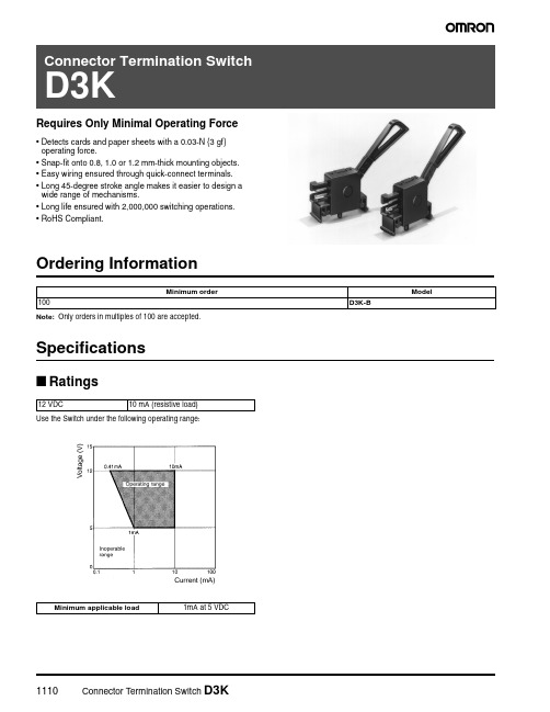
1110Connector Termination Switch D3KRequires Only Minimal Operating Force•Detects cards and paper sheets with a 0.03-N {3 gf} operating force.•Snap-fit onto 0.8, 1.0 or 1.2 mm-thick mounting objects.•Easy wiring ensured through quick-connect terminals.•Long 45-degree stroke angle makes it easier to design a wide range of mechanisms.•Long life ensured with 2,000,000 switching operations.•RoHS Compliant.Ordering InformationNote: Only orders in multiples of 100 are accepted.SpecificationsI RatingsUse the Switch under the following operating range:Minimum orderModel100D3K-B12 VDC10 mA (resistive load)Minimum applicable load1mA at 5 VDCConnector Termination Switch D3K1111I CharacteristicsNote: These values are possible on condition that the actuator of the D3K is operated up to the total travel position (TTP).I Contact FormOperating speed 0.1 to 100 mm/s Operating frequencyMechanical: Electrical:30 operations per minute 30 operations per minuteInsulation resistance 100 M Ω min. (at 250 VDC)Contact resistance 200 M Ω min. (initial value)Dielectric strength 250 VAC, 60/80 Hz for 1 min. between contacts of the same polarity250 VAC, 50/60 Hz for 1 min. between each terminal and non-current-carrying metal part Vibration resistance Malfunction:10 to 55 Hz, 1.5-min. double amplitude (at a contact separation time of 1 min. max.) (see note)Shock resistanceMalfunction:300 m/s 2 {30G} (at a contact separation time of 1 ms max) (see note)Life expectancy (see note)Mechanical:Electrical:2,000,000 (30 operations/min.)2,000,000 (30 operations/min.)Degree of protection (IP code)IP00Degree of protection against electrical shockClass III Ambient temperature Operating: -10°C to 70°C (with no icing or condensation)Ambient humidity Operating:35% to 85% (for 5°C to 35°C)WeightApprox. 0.9 g1112Connector Termination Switch D3KDimensionsNote:1.All units are in millimeters unless otherwise indicated.2.Unless specified, a tolerance of ±0.4 mm applies to all dimensions.I Dimensions and Operating CharacteristicsD3KOF max.0.03 N {3 gf}TTF max.0.05 N {5 gf}TTP max.11.4 mm {5°}FP max.28.7 mm {50°}OP21.6±2 mm (30±5°)Connector Termination Switch D3K1113PrecautionsI Mounting DimensionsMountingRefer to the following mounting hole dimensions and be sure that the burred side is opposite to the Switch mounting side.If further mounting security is required for the prevention of rattling, contact your OMRON representative.By changing the 1.9±0.05-dia. hole to a 1.7 to 1.8-dia. hole, the pin on the Switch side will need to be pressed in. This will reduce the clattering of the pin.•Plate thickness t=0.8•Plate thickness t=1.0•Plate thickness t=1.2Note:The switch lever is set in the direction indicated by an arrow inthe above illustration.Lever LoadDo not impose loads in the following directions on the lever, other-wise the D3K may be damaged or malfunction.Operating ObjectThe operating object must fully press the lever when the operatingobject travels and must be perfectly separated from the lever when the operating object is in the free position. The operating object must not be pressed excessively to exceed the TTP, otherwise the D3K may be damaged. Be sure that the operating object imposes a proper load on the lever according to the motion of the lever.I ConnectorUse the following type CT connectors of Nippon AMP for wiring the D3K:The above connectors are not sold by OMRON. Contact the following offices for these connectors:•AMP (Japan), Ltd.Phone: 81-44-844-8111•AMP Inc. (U.S.A.)Phone 1-800-522-6752•AMP of Great Britain Ltd.Phone: 44-181-954-2356•AMP Products Pacific Ltd. (Hong Kong)Phone: 852-2735-1628Press-fit connector173977-2Crimp-style connector housing179228-2Crimp-style connector contact179227-1Terms and Conditions of Sale1.Offer; Acceptance. These terms and conditions (these "T erms") are deemedpart of all quotations, acknowledgments, invoices, purchase orders and other documents, whether electronic or in writing, relating to the sale of products or services (collectively, the "Products") by Omron Electronic Components LLC ("Seller"). Seller hereby objects to any terms or conditions proposed in Buyer's purchase order or other documents which are inconsistent with, or in addition to, these T erms.2. Prices; Payment. All prices stated are current, subject to change withoutnotice by Seller. Buyer agrees to pay the price in effect at time of shipment.Payments for Products received are due net 30 days unless otherwise stated in the invoice.3. Discounts. Cash discounts, if any, will apply only on the net amount ofinvoices sent to Buyer after deducting transportation charges, taxes and duties, and will be allowed only if (i) the invoice is paid according to Seller's payment terms and (ii) Buyer has no past due amounts owing to Seller.4. Currencies. If the prices quoted herein are in a currency other than U.S. dol-lars, Buyer shall make remittance to Seller at the then current exchange rate most favorable to Seller and which is available on the due date; provided that if remittance is not made when due, Buyer will convert the amount to U.S. dol-lars at the then current exchange rate most favorable to Seller available during the period between the due date and the date remittance is actually made. 5. Governmental Approvals. Buyer shall be responsible for, and shall bear allcosts involved in, obtaining any government approvals required for the impor-tation or sale of the Products.6. Taxes. All taxes, duties and other governmental charges (other than generalreal property and income taxes), including any interest or penalties thereon, imposed directly or indirectly on Seller or required to be collected directly or indirectly by Seller for the manufacture, production, sale, delivery, importation, consumption or use of the Products sold hereunder (including customs duties and sales, excise, use, turnover and license taxes) shall be charged to and remitted by Buyer to Seller.7. Financial. If the financial position of Buyer at any time becomes unsatisfactoryto Seller, Seller reserves the right to stop shipments or require satisfactory security or payment in advance. If Buyer fails to make payment or otherwise comply with these T erms or any related agreement, Seller may (without liability and in addition to other remedies) cancel any unshipped portion of Products sold hereunder and stop any Products in transit until Buyer pays all amounts, including amounts payable hereunder, whether or not then due, which are owing to it by Buyer. Buyer shall in any event remain liable for all unpaid accounts.8. Cancellation; Etc. Orders are not subject to rescheduling or cancellationunless Buyer indemnifies Seller fully against all costs or expenses arising in connection therewith.9. Force Majeure. Seller shall not be liable for any delay or failure in deliveryresulting from causes beyond its control, including earthquakes, fires, floods, strikes or other labor disputes, shortage of labor or materials, accidents to machinery, acts of sabotage, riots, delay in or lack of transportation or the requirements of any government authority.10. Shipping; Delivery. Unless otherwise expressly agreed in writing by Seller:1. Shipments shall be by a carrier selected by Seller;2. Such carrier shall act as the agent of Buyer and delivery to such carriershall constitute delivery to Buyer;3.All sales and shipments of Products shall be FOB shipping point (unlessotherwise stated in writing by Seller), at which point title to and all risk ofloss of the Products shall pass from Seller to Buyer, provided that Sellershall retain a security interest in the Products until the full purchase price is paid by Buyer;4. Delivery and shipping dates are estimates only.5.Seller will package Products as it deems proper for protection againstnormal handling and extra charges apply to special conditions.11.Claims. Any claim by Buyer against Seller for shortage or damage to theProducts occurring before delivery to the carrier must be presented in writing to Seller within 30 days of receipt of shipment and include the original trans-portation bill signed by the carrier noting that the carrier received the Products from Seller in the condition claimed. 12. Warranties. (a) Exclusive Warranty. Seller's exclusive warranty is that theProducts will be free from defects in materials and workmanship for a period of twelve months from the date of sale by Seller (or such other period expressed in writing by Seller). Seller disclaims all other warranties, express or implied.(b) Limitations. SELLER MAKES NO WARRANTY OR REPRESENT ATION,EXPRESS OR IMPLIED, ABOUT NON-INFRINGEMENT, MERCHANT ABIL-ITY OR FITNESS FOR A PARTICULAR PURPOSE OF THE PRODUCTS.BUYER ACKNOWLEDGES THAT IT ALONE HAS DETERMINED THAT THE PRODUCTS WILL SUIT ABL Y MEET THE REQUIREMENTS OF THEIR INTENDED USE. Seller further disclaims all warranties and responsibility of any type for claims or expenses based on infringement by the Products or oth-erwise of any intellectual property right. (c) Buyer Remedy. Seller's sole obli-gation hereunder shall be to replace (in the form originally shipped with Buyer responsible for labor charges for removal or replacement thereof) the non-complying Product or, at Seller's election, to repay or credit Buyer an amount equal to the purchase price of the Product; provided that in no event shall Seller be responsible for warranty, repair, indemnity or any other claims or expenses regarding the Products unless Seller's analysis confirms that the Products were properly handled, stored, installed and maintained and not sub-ject to contamination, abuse, misuse or inappropriate modification. Return of any Products by Buyer must be approved in writing by Seller before shipment.Seller shall not be liable for the suitability or unsuitability or the results from the use of Products in combination with any electrical or electronic components, circuits, system assemblies, or any other materials or substances or environ-ments. Any advice, recommendations or information given orally or in writing are not to be construed as an amendment or addition to the above warranty.13.Limitation on Liability; Etc. SELLER SHALL NOT BE LIABLE FOR SPECIAL,INDIRECT, INCIDENT AL OR CONSEQUENTIAL DAMAGES, LOSS OF PROFITS OR PRODUCTION OR COMMERCIAL LOSS IN ANY WAY CON-NECTED WITH THE PRODUCTS, WHETHER SUCH CLAIM IS BASED IN CONTRACT, WARRANTY, NEGLIGENCE OR STRICT LIABILITY. Further, in no event shall liability of Seller exceed the individual price of the Product on which liability is asserted.14.Indemnities. Buyer shall indemnify and hold harmless Seller, its affiliates andits employees from and against all liabilities, losses, claims, costs and expenses (including attorney's fees and expenses) related to any claim, inves-tigation, litigation or proceeding (whether or not Seller is a party) which arises or is alleged to arise from Buyer's acts or omissions under these T erms or in any way with respect to the Products. Without limiting the foregoing, Buyer (at its own expense) shall indemnify and hold harmless Seller and defend or settle any action brought against Seller to the extent that it is based on a claim that any Product made to Buyer specifications infringed intellectual property rights of another party.15.Property; Confidentiality. The intellectual property embodied in the Products isthe exclusive property of Seller and its affiliates and Buyer shall not attempt to duplicate it in any way without the written permission of Seller. Notwithstand-ing any charges to Buyer for engineering or tooling, all engineering and tooling shall remain the exclusive property of Seller. All information and materials sup-plied by Seller to Buyer relating to the Products are confidential and propri-etary, and Buyer shall limit distribution thereof to its trusted employees and strictly prevent disclosure to any third party.16.Miscellaneous. (a) Waiver. No failure or delay by Seller in exercising any rightand no course of dealing between Buyer and Seller shall operate as a waiver of rights by Seller. (b) Assignment. Buyer may not assign its rights hereunder without Seller's written consent. (c) Law. These T erms are governed by Illi-nois law (without regard to conflict of law principles). Federal and state courts in Illinois shall have exclusive jurisdiction for any dispute hereunder.(d)Amendment. These T erms constitute the entire agreement between Buyerand Seller relating to the Products, and no provision may be changed or waived unless in writing signed by the parties. (e) Severability. If any provision hereof is rendered ineffective or invalid, such provision shall not invalidate any other provision. (f) Setoff. Buyer shall have no right to set off any amounts against the amount owing in respect of this invoice.. (g) Definitions. As used herein, "including" means "including without limitation".Certain Precautions on Specifications and Use1.Suitability for Use. Seller shall not be responsible for conformity with any stan-dards, codes or regulations which apply to the combination of the Product in Buyer's application or use of the Product. At Buyer's request, Seller will pro-vide applicable third party certification documents identifying ratings and limita-tions of use which apply to the Product. This information by itself is not sufficient for a complete determination of the suitability of the Product in combi-nation with the end product, machine, system, or other application or use.Buyer shall be solely responsible for determining appropriateness of the partic-ular Product with respect to Buyer's application, product or system. Buyer shall take application responsibility in all cases but the following is a non-exhaustive list of applications for which particular attention must be given: (i)Outdoor use, uses involving potential chemical contamination or electrical interference, or conditions or uses not described in this document.(ii)Energy control systems, combustion systems, railroad systems, aviation systems, medical equipment, amusement machines, vehicles, safety equipment, and installations subject toseparate industry or government regulations.(iii)Use in consumer products or any use in significant quantities.(iv)Systems, machines and equipment that could present a risk to life orproperty. Please know and observe all prohibitions of use applicable to this product.NEVER USE THE PRODUCT FOR AN APPLICATION INVOLVING SERIOUS RISK TO LIFE OR PROPERTY WITHOUT ENSURING THAT THE SYSTEM AS A WHOLE HAS BEEN DESIGNED TO ADDRESS THE RISKS, AND THAT THE OMRON PRODUCT IS PROPERL Y RATED AND INST ALLED FOR THE INTENDED USE WITHIN THE OVERALL EQUIPMENT OR SYSTEM.2.Programmable Products. Seller shall not be responsible for the user'sprogramming of a programmable product, or any consequence thereof.3.Performance Data. Performance data given in this publication is provided as aguide for the user in determining suitability and does not constitute a warranty.It may represent the result of Seller's test conditions, and the users must corre-late it to actual application requirements. Actual performance is subject to Seller's Warranty and Limitations of Liability.4.Change in Specifications. Product specifications and accessories may bechanged at any time based on improvements and other reasons. It is our prac-tice to change part numbers when published ratings or features are changed,or when significant construction changes are made. However, some specifica-tions of the Product may be changed without any notice. When in doubt, spe-cial part numbers may be assigned to fix or establish key specifications for your application. Please consult with your Seller representative at any time to con-firm actual specifications of purchased Product.5.Errors and Omissions. The information in this publication has been carefullychecked and is believed to be accurate; however, no responsibility is assumed for clerical, typographical or proofreading errors, or omissions.6.RoHS Compliance. Where indicated, our products currently comply, to the bestof our knowledge as of the date of this publication, with the requirements of the European Union's Directive on the Restriction of certain Hazardous Sub-stances ("RoHS"), although the requirements of RoHS do not take effect until July 2006. These requirements may be subject to change. Please consult our website for current information.OMRON ON-LINEGlobal - USA - Canada - http://www.omron.caCat. No. JB301-E3-01Printed in USAOMRON CANADA, INC.885 Milner AvenueT oronto, Ontario M1B 5V8416-286-6465OMRON ELECTRONIC COMPONENTS LLC55 E. Commerce Drive, Suite B Schaumburg, IL 60173847-882-22883/05 Specifications subject to change without noticeComplete “Terms and Conditions of Sale” for product purchase and use are on Omron’s website at – under the “About Us” tab, in the Legal Matters section.ALL DIMENSIONS SHOWN ARE IN MILLIMETERS.T o convert millimeters into inches, multiply by 0.03937. T o convert grams into ounces, multiply by 0.03527.。
switch教程
switch教程1. 了解开关(Switch)的基本概念开关是一种常见的电气元件,用于控制电路中的电气信号通断。
它通常有两个状态:打开和关闭,通过切换开关的位置来切换这两种状态。
2. 开关的分类开关可以根据不同的特点进行分类。
常见的开关分类有以下几种:- 常开(normally open)开关:在打开状态下才允许电流通过。
- 常闭(normally closed)开关:在关闭状态下才允许电流通过。
- 切换(toggle)开关:在每次切换时,开关会保持在打开或关闭状态,直到下一次切换。
3. 开关的符号表示在电路图中,开关通常用特定的符号进行表示。
常见的开关符号有以下几种:- 常开开关的符号表示为一个直线和一个连接点,表示在打开状态下电流能够通过。
- 常闭开关的符号表示为一个连接的环,表示在关闭状态下电流能够通过。
- 切换开关的符号表示为一个直线和一个连接点,通常伴有一个箭头表示切换的位置。
4. 开关的连接方式开关可以根据不同的连接方式来实现不同的控制功能。
常见的开关连接方式有以下几种:- 单极单 throw(SPST):这是一种简单的开关连接方式,只有一个输入和一个输出。
它只能实现通断控制。
- 单极双 throw(SPDT):这种开关连接方式有一个输入和两个输出。
它可以实现两个电路中的通断控制。
- 双极双 throw(DPDT):这种开关连接方式有两个输入和两个输出,可以实现更复杂的电路控制。
5. 开关的使用场景开关被广泛应用于各种电路和设备中。
一些常见的开关使用场景包括:- 家庭电路:用于控制灯光和电器设备的通断。
- 电子设备:用于控制电源和功能开关。
- 自动化系统:用于控制机器人和自动化生产线等设备。
6. 开关的安装和维护在安装和维护开关时,需要注意以下几点:- 确保正确连接开关的输入和输出线路。
- 确保开关固定牢固,以防止松动或掉落。
- 定期检查开关的工作状态,及时更换损坏或老化的开关。
以上就是关于开关(Switch)的基本介绍和使用指南。
switch语句用法
switch语句⽤法
在C语⾔中,switch语句是开关语句,⼀般与case、break、default配合使⽤,对流程进⾏控制。
switch作为⼀个开关,当变量表达式的值对应case中的值时,执⾏case后⾯的语句后跳出switch语句,如果都不符合则执⾏default后⾯的语句后跳出switch 语句。
1switch语句⽤法规则
1.在⼀个switch中可以有任意数量的case语句。
每个case后跟⼀个要⽐较的值和⼀个冒号。
2.case后的类型必须与switch中的变量具有相同的数据类型,且必须是⼀个常量或字⾯量。
3.当被测试的变量等于case中的常量时,case后跟的语句将被执⾏,直到遇到break语句为⽌。
4.当遇到break语句时,switch终⽌,控制流将跳转到switch语句后的下⼀⾏。
5.不是每⼀个case都需要包含break。
如果case语句不包含break,控制流将会继续后续的case,直到遇到break为⽌。
6.⼀个switch语句可以有⼀个可选的defaultcase,出现在switch的结尾。
default case可⽤于在上⾯所有case都不为真时执⾏⼀个任务。
default case中的break语句不是必需的。
Option Switch常用开关
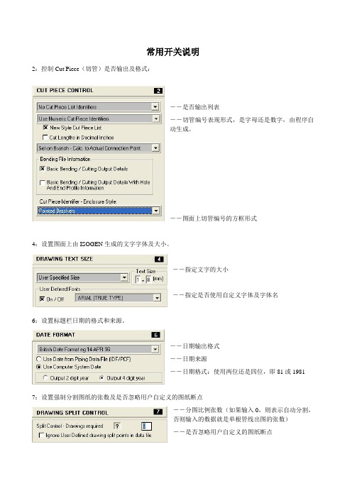
常用开关说明2:控制Cut Piece(切管)是否输出及格式:――是否输出列表――切管编号表现形式,是字母还是数字,由程序自动生成。
――图面上切管编号的方框形式4:设置图面上由ISOGEN生成的文字字体及大小。
――指定文字的大小――指定是否使用自定义字体及字体名6:设置标题栏日期的格式和来源。
――日期输出格式――日期来源――日期格式:使用两位还是四位,即81或1981 7:设置强制分割图纸的张数及是否忽略用户自定义的图纸断点――分图比例张数(如果输入0,则表示自动分割,否则输入的数据就是单根管线出图的张数)――是否忽略用户自定义的图纸断点9:设置标注格式:――支撑的标注形式――垫片的标注形式――文字与标注线位置关系:中间或上方――是否显示余量:当要显示带余量的焊点时要打开。
――是否将管道与弯头的标注合并10,11,12,13:这四个开关是用来设置画图区的四个边框距离图框的四边的距离。
14:是用来选择用多大的图纸出图的。
如果你选择了A3图纸出图,那么你的图框在Project Manger也要选A3的图框。
17:设置是否在管件上显示流向箭头19/20:坡度管线标示(是以角度的形式显示还是以百分比的形式表示等等)21:设置材料表的输出样式。
FABRICATION与ERECTION合并输出;只输出FABRICATION数据;只输出ERECTION数据;只输出材料表,没有图形等。
(FABRICA TION:制造(shop);ERECTION:安装)22:切管余量值(On-Shore,Off-Shore),例如可以在这设置单管图上的焊接余量值23:设置材料表的输出格式的。
Special Material List是输出的管件每个都单独统计,不再合并在一起。
Normal Material List with Alpha pointer是指输出的材料表的PT-NO用字母来统计。
也可以不输出材料表。
――开关材料表――材料表类型――材料表样式:共有4种样式――是否使用自定义材料表文件――带有材料分类名和材料分组名,并带有分割线――没有材料分类名和材料分组名――没有材料分类名和材料分组名,但无分割线24:设置当同一管线号被分成多张单管图输出时,材料表是按单管图分图纸生成还是整个线号生成一个材料表及其显示的精度――按单管图分图纸生成材料表 ――按整个管线号生成一个材料表 ――显示精度25:设置材料表和标题的位置。
机柜英语
1 backplane 背板3 benchtop supply 工作台电源9 chassis 机架87 substrate 基板106 Ground 地电位110 circuit breaker 断路器母线:Busbar断路器:Breaker刀闸(隔离开关):Isolator分接头:tap电压voltage电流current母线bus交流AC故障fault静态static (state)动态dynamic (state)保护断路器circuit breakerrabbet 插槽flexible 柔性的rivit 铆钉mount 支架module 模块malfunction 故障ways 导轨ID=inside diameterstop 挡块filter 滤波器fuse 保险丝radiator 散热器regulator 稳压器socket 插孔tape 胶带servo 伺服机构spring 触发server 服务器cable 电缆mark 标志conduction (track) 导线(通道)板:board线网:net段:segmentcabinet 柜card (电子)板、卡Contactor 接触器、触头Console 控制台Connector 联接器、接线盒Control & instrument 仪控Direct current DC 直流(电)Disconnector 隔离器、隔离开关Earth fault 接地故障Earth connector 接地线、接地Earth lead 接地线、接地Failure FAIL 失败Faulty operation 误操作Feed 馈、供给Feedback 反馈Feed forward 前馈Flip-flop 触发器、双稳态电路Flowmeter 流量计Forbid 禁止Force 强制Gang 班、组Increase INC 增加Index 索引、指示Indicator 指示器Induced draft fan IDF 引风机Instruction 说明书、指南、指导Instrument 仪器Insulate 绝缘、绝热、隔离Insulator 绝缘子Intake 输入端、进线Intermediate relay 中间继电器Jumper 跳线、跨接Junction box 接线盒Label 标号、标签Lightning arrestor 避雷器Limit LMT 极限、限制Limiter 限制器、限位开关Local repair 现场检修Manometer 压力表Modulating valve 调节阀Motor MTR 马达Motor control center MCC 马达控制中心Multimeter 万用表Naught line 零线Negative pressure NEG PRESS 负压Optional 可选的Option switch 选择开关Plug 塞子、栓、插头Plug socket 插座Pre-alarm 预报警Pre-alarm 预报警Potential transformer PT 电压互感器Push button 按钮Rectifier 整流器Relay 继电器Shield 屏蔽层Short circuit 短路Single blade switch 单刀开关Socket 插座Symbol 符号Template 模板、样板Terminal 端子、接线柱Transmitter XMITEER 变送器Valve VLV 阀门Warning 报警。
Snap Action Switch D2F 小型快速切换开关说明书

1054Snap Action Switch D2FSubminiature Snap Action Switch•Super compact, ideal for PCB mounting•Switches 3 A loads (general-purpose), 1 A loads (low force general-purpose) and 0.1 A loads (microvoltage/microcurrent)•Long life span assured by high-precision dual spring reverse-action mechanism•Flux penetration prevented by using an insert terminal and allowing a height difference at the case bottom•Ideal for a wide variety of applications from household appliances and office equipment to audio equipment and communications equipment •RoHS CompliantOrdering InformationActuator Contacttype Model Contact OFModelTerminal typePCB Self-supportingSoldered Right-angle Left-angle Pin plungerMicrovoltage/ current Low force 75 g D2F-01F D2F-01F-T D2F-01F-D D2F-01F-A D2F-01F-A1Standard 150 g D2F-01D2F-01-T D2F-01-D D2F-01-A D2F-01-A1General- purposeLow force 75 g D2F-F D2F-F-T D2F-F-D D2F-F-A D2F-F-A1Standard 150 g D2F D2F-T D2F-D D2F-A D2F-A1Hinge leverMicrovoltage/ current Low force 25 g D2F-01FL D2F-01FL-T D2F-01FL-D D2F-01FL-A D2F-01FL-A1Standard 80 g D2F-01L D2F-01L-T D2F-01L-D D2F-01L-A D2F-01L-A1General- purposeLow force 25 g D2F-FL D2F-FL-T D2F-FL-D D2F-FL-A D2F-FL-A1Standard 80 g D2F-L D2F-L-T D2F-L-D D2F-L-A D2F-L-A1Simulated roller leverMicrovoltage/ current Low force 40 g D2F-01FL3D2F-01FL3-T D2F-01FL3-D D2F-01FL3-A D2F-01FL3-A1Standard 80 g D2F-01L3D2F-01L3-T D2F-01L3-D D2F-01L3-A D2F-01L3-A1General- purposeLow force 40 g D2F-FL3D2F-FL3-T D2F-FL3-D D2F-FL3-A D2F-FL3-A1Standard 80 g D2F-L3D2F-L3-T D2F-L3-D D2F-L3-A D2F-L3-A1Roller leverMicrovoltage/ current Low force 40 g D2F-01FL2 —D2F-01FL2-D D2F-01FL2-A D2F-01FL2-A1Standard 80 g D2F-01L2D2F-01L2-T D2F-01L2-D D2F-01L2-A D2F-01L2-A1General- purposeLow force 40 g D2F-FL2D2F-FL2-T D2F-FL2-D D2F-FL2-A D2F-FL2-A1Standard 80 gD2F-L2D2F-L2-TD2F-L2-DD2F-L2-AD2F-L2-A1Snap Action Switch D2F1055SpecificationsI CharacteristicsNote:Data shown are of initial value.I Operating CharacteristicsI RatingsNote:When using an inductive load or motor load, consult OMRON.Operating speed 1 to 500 mm/second (0.04 to 19.7 in./second)Operating frequency Mechanical 200 operations per minute (pin plunger actuator type)Electrical30 operations per minute (pin plunger actuator type)Contact resistanceGeneral-purpose type 30 m Ω max. (initial)Microvoltage/microcurrent load type100 m Ω max. (initial)Insulation resistance 100 M Ω min. at 500 VDCDielectric strength600 VAC, 50/60 Hz for 1 minute between terminals of same polarity 1,500 VAC, 50/60 Hz for 1 minute between current-carrying parts and groundVibration Malfunction durability 10 to 55 Hz, 1.5 mm double amplitude Shock Malfunction durability 300 m/s 2 min. (approx. 30 g min.)Ambient temperature Operating -25° to 65°C with no icingHumidity Operating 45% to 85% ay 5° to 35°CService life Mechanical 1 million operations min. (OT: full stroke)Electrical30,000 operations min. (rated load)WeightApprox. 0.5 gCharacteristics Part numberD2F-01F-@, D2F-F-@D2F-01-@, D2F-@ D2F-01FL-@, D2F-FL-@ D2F-01L-@, D2F-L-@ D2F-01FL3-@, D2F-FL3-@OF max.75 g 150 g 25 g 80 g 40 g RF min. 5 g20 g2 g 5 g 2 g PT max.0.5 mm (0.020 in)0.5 mm (0.020 in)———OT min.0.25 mm (0.009 in)0.25 mm (0.009 in)0.55 mm (0.022 in)0.55 mm (0.022 in)0.5 mm (0.020 in)MD max.0.12 mm (0.005 in)0.12 mm (0.005 in)0.5 mm (0.020 in)0.5 mm (0.020 in)0.45 mm (0.177 in)OP 5.5 ± 0.3 mm(0.22 ± 0.012 in) 5.5 ± 0.3 mm (0.22 ± 0.012 in) 6.8 ± 1.5 mm (0.267 ± 0.059 in) 6.8 ± 1.5 mm(0.267 ± 0.059 in)8.5 ± 1.2 mm(0.335 ± 0.047 in)FP max.——10 mm (0.394 in)10 mm (0.394 in)13 mm (0.512 in)Characteristics Part numberD2F-01L3-@, D2F-L3-@ D2F-01FL2-@, D2F-FL2-@ D2F-01L2-@, D2F-L2-@OF max.80 g 40 g 80 g RF min. 5 g 2 g 5 g PT max.———OT min.0.5 mm (0.020 in)0.55 mm (0.022 in)0.55 mm (0.022 in)MD max.0.45 mm (0.177 in)0.5 mm (0.020 in)0.5 mm (0.020 in)OP 8.5 ± 1.2 mm(0.335 ± 0.047 in)13 ± 2.0 mm(0.512 ± 0.079 in)13 ± 2.0 mm(0.512 ± 0.079 in)FP max.13 mm (0.512 in)16.5 mm (0.650 in)16.5 mm (0.650 in)Rated VoltageResistive loadMicrovoltage/current General-purposeLow force Standard Low force Standard125 VAC —— 1 A 3 A 30 VDC0.1 A0.1 A0.5 A2 A1056Snap Action Switch D2FI Contact FormI ApprovalsUL (File No. E41515), CSA (File No. LR21642), EN conforms 61058-1Note:The rated values approved by each of the safety standards (e.g.UL,CSA) may be different from the performance characteristics individuallydefined in this catalog.Engineering DataMechanical service lifeNote:1.Values are for pin plunger actuator type.Electrical service lifeType Rating D2F Series, D2F-01 Series3 A, 125 VAC 1 A, 125 VAC 2 A, 30 VDC 0.5 A, 30 VDC 0.1 A, 30 VDCSnap Action Switch D2F1057DimensionsUnit: mm (inch)Note:1.Unless otherwise specified, a tolerance of ± 0.4 mm applies to all dimensions.2.Omitted dimensions are the same as pin plunger type.3.Letters and numbers which identify the terminal are put in the blank box of the part number.4.The above illustrations and dimensions are for models with PCB terminals. Refer to “Terminals” for models with self-supporting, solderand right/left angle terminals.I Pin PlungerD2F-01-@D2F-01F-@D2F-@D2F-F-@I Hinge LeverD2F-01L-@D2F-01FL-@D2F-L-@D2F-FL-@I Simulated Roller LeverD2F-01L3-@D2F-01FL3-@D2F-L3-@D2F-FL3-@I Roller LeverD2F-01L2-@D2F-01FL2-@D2F-L2-@D2F-FL2-@I TerminalsD2F type PCB terminalD2F-T typeSelf-supporting terminalD2F-D typeSoldered terminalD2F-A typeRight-angle terminalD2F-A1 typeLeft-angle terminal1058Snap Action Switch D2FPrecautionsI MountingMount the D2F switch onto the PC board as shown in the following diagram, using 2-pitch (2 x 2.54 mm) terminal spacing.I PC Board MachiningI DimensionsThe use of molded components is recommended for mounting pur-poses.I Molded Pin Mounting Diagram When screw mounting, use M2 screws together with washers. Fas-ten the screws applying 0.8 to 1 kg-cm tightening torque.I Mounting Hole MachiningI DimensionsWhen soldering, use 6:4 solder and a 60 W soldering iron, and com-plete soldering within 3 seconds. After soldering, do not apply exter-nal force to the soldered area for about 1 minute.Allow sufficient insulation distance between terminals and betweenterminals and ground.Snap Action Switch D2F1059Terms and Conditions of Sale1.Offer; Acceptance. These terms and conditions (these "T erms") are deemedpart of all quotations, acknowledgments, invoices, purchase orders and other documents, whether electronic or in writing, relating to the sale of products or services (collectively, the "Products") by Omron Electronic Components LLC ("Seller"). Seller hereby objects to any terms or conditions proposed in Buyer's purchase order or other documents which are inconsistent with, or in addition to, these T erms.2. Prices; Payment. All prices stated are current, subject to change withoutnotice by Seller. Buyer agrees to pay the price in effect at time of shipment.Payments for Products received are due net 30 days unless otherwise stated in the invoice.3. Discounts. Cash discounts, if any, will apply only on the net amount ofinvoices sent to Buyer after deducting transportation charges, taxes and duties, and will be allowed only if (i) the invoice is paid according to Seller's payment terms and (ii) Buyer has no past due amounts owing to Seller.4. Currencies. If the prices quoted herein are in a currency other than U.S. dol-lars, Buyer shall make remittance to Seller at the then current exchange rate most favorable to Seller and which is available on the due date; provided that if remittance is not made when due, Buyer will convert the amount to U.S. dol-lars at the then current exchange rate most favorable to Seller available during the period between the due date and the date remittance is actually made. 5. Governmental Approvals. Buyer shall be responsible for, and shall bear allcosts involved in, obtaining any government approvals required for the impor-tation or sale of the Products.6. Taxes. All taxes, duties and other governmental charges (other than generalreal property and income taxes), including any interest or penalties thereon, imposed directly or indirectly on Seller or required to be collected directly or indirectly by Seller for the manufacture, production, sale, delivery, importation, consumption or use of the Products sold hereunder (including customs duties and sales, excise, use, turnover and license taxes) shall be charged to and remitted by Buyer to Seller.7. Financial. If the financial position of Buyer at any time becomes unsatisfactoryto Seller, Seller reserves the right to stop shipments or require satisfactory security or payment in advance. If Buyer fails to make payment or otherwise comply with these T erms or any related agreement, Seller may (without liability and in addition to other remedies) cancel any unshipped portion of Products sold hereunder and stop any Products in transit until Buyer pays all amounts, including amounts payable hereunder, whether or not then due, which are owing to it by Buyer. Buyer shall in any event remain liable for all unpaid accounts.8. Cancellation; Etc. Orders are not subject to rescheduling or cancellationunless Buyer indemnifies Seller fully against all costs or expenses arising in connection therewith.9. Force Majeure. Seller shall not be liable for any delay or failure in deliveryresulting from causes beyond its control, including earthquakes, fires, floods, strikes or other labor disputes, shortage of labor or materials, accidents to machinery, acts of sabotage, riots, delay in or lack of transportation or the requirements of any government authority.10. Shipping; Delivery. Unless otherwise expressly agreed in writing by Seller:1. Shipments shall be by a carrier selected by Seller;2. Such carrier shall act as the agent of Buyer and delivery to such carriershall constitute delivery to Buyer;3.All sales and shipments of Products shall be FOB shipping point (unlessotherwise stated in writing by Seller), at which point title to and all risk ofloss of the Products shall pass from Seller to Buyer, provided that Sellershall retain a security interest in the Products until the full purchase price is paid by Buyer;4. Delivery and shipping dates are estimates only.5.Seller will package Products as it deems proper for protection againstnormal handling and extra charges apply to special conditions.11.Claims. Any claim by Buyer against Seller for shortage or damage to theProducts occurring before delivery to the carrier must be presented in writing to Seller within 30 days of receipt of shipment and include the original trans-portation bill signed by the carrier noting that the carrier received the Products from Seller in the condition claimed. 12. Warranties. (a) Exclusive Warranty. Seller's exclusive warranty is that theProducts will be free from defects in materials and workmanship for a period of twelve months from the date of sale by Seller (or such other period expressed in writing by Seller). Seller disclaims all other warranties, express or implied.(b) Limitations. SELLER MAKES NO WARRANTY OR REPRESENT ATION,EXPRESS OR IMPLIED, ABOUT NON-INFRINGEMENT, MERCHANT ABIL-ITY OR FITNESS FOR A PARTICULAR PURPOSE OF THE PRODUCTS.BUYER ACKNOWLEDGES THAT IT ALONE HAS DETERMINED THAT THE PRODUCTS WILL SUIT ABL Y MEET THE REQUIREMENTS OF THEIR INTENDED USE. Seller further disclaims all warranties and responsibility of any type for claims or expenses based on infringement by the Products or oth-erwise of any intellectual property right. (c) Buyer Remedy. Seller's sole obli-gation hereunder shall be to replace (in the form originally shipped with Buyer responsible for labor charges for removal or replacement thereof) the non-complying Product or, at Seller's election, to repay or credit Buyer an amount equal to the purchase price of the Product; provided that in no event shall Seller be responsible for warranty, repair, indemnity or any other claims or expenses regarding the Products unless Seller's analysis confirms that the Products were properly handled, stored, installed and maintained and not sub-ject to contamination, abuse, misuse or inappropriate modification. Return of any Products by Buyer must be approved in writing by Seller before shipment.Seller shall not be liable for the suitability or unsuitability or the results from the use of Products in combination with any electrical or electronic components, circuits, system assemblies, or any other materials or substances or environ-ments. Any advice, recommendations or information given orally or in writing are not to be construed as an amendment or addition to the above warranty.13.Limitation on Liability; Etc. SELLER SHALL NOT BE LIABLE FOR SPECIAL,INDIRECT, INCIDENT AL OR CONSEQUENTIAL DAMAGES, LOSS OF PROFITS OR PRODUCTION OR COMMERCIAL LOSS IN ANY WAY CON-NECTED WITH THE PRODUCTS, WHETHER SUCH CLAIM IS BASED IN CONTRACT, WARRANTY, NEGLIGENCE OR STRICT LIABILITY. Further, in no event shall liability of Seller exceed the individual price of the Product on which liability is asserted.14.Indemnities. Buyer shall indemnify and hold harmless Seller, its affiliates andits employees from and against all liabilities, losses, claims, costs and expenses (including attorney's fees and expenses) related to any claim, inves-tigation, litigation or proceeding (whether or not Seller is a party) which arises or is alleged to arise from Buyer's acts or omissions under these T erms or in any way with respect to the Products. Without limiting the foregoing, Buyer (at its own expense) shall indemnify and hold harmless Seller and defend or settle any action brought against Seller to the extent that it is based on a claim that any Product made to Buyer specifications infringed intellectual property rights of another party.15.Property; Confidentiality. The intellectual property embodied in the Products isthe exclusive property of Seller and its affiliates and Buyer shall not attempt to duplicate it in any way without the written permission of Seller. Notwithstand-ing any charges to Buyer for engineering or tooling, all engineering and tooling shall remain the exclusive property of Seller. All information and materials sup-plied by Seller to Buyer relating to the Products are confidential and propri-etary, and Buyer shall limit distribution thereof to its trusted employees and strictly prevent disclosure to any third party.16.Miscellaneous. (a) Waiver. No failure or delay by Seller in exercising any rightand no course of dealing between Buyer and Seller shall operate as a waiver of rights by Seller. (b) Assignment. Buyer may not assign its rights hereunder without Seller's written consent. (c) Law. These T erms are governed by Illi-nois law (without regard to conflict of law principles). Federal and state courts in Illinois shall have exclusive jurisdiction for any dispute hereunder.(d)Amendment. These T erms constitute the entire agreement between Buyerand Seller relating to the Products, and no provision may be changed or waived unless in writing signed by the parties. (e) Severability. If any provision hereof is rendered ineffective or invalid, such provision shall not invalidate any other provision. (f) Setoff. Buyer shall have no right to set off any amounts against the amount owing in respect of this invoice.. (g) Definitions. As used herein, "including" means "including without limitation".Certain Precautions on Specifications and Use1.Suitability for Use. Seller shall not be responsible for conformity with any stan-dards, codes or regulations which apply to the combination of the Product in Buyer's application or use of the Product. At Buyer's request, Seller will pro-vide applicable third party certification documents identifying ratings and limita-tions of use which apply to the Product. This information by itself is not sufficient for a complete determination of the suitability of the Product in combi-nation with the end product, machine, system, or other application or use.Buyer shall be solely responsible for determining appropriateness of the partic-ular Product with respect to Buyer's application, product or system. Buyer shall take application responsibility in all cases but the following is a non-exhaustive list of applications for which particular attention must be given: (i)Outdoor use, uses involving potential chemical contamination or electrical interference, or conditions or uses not described in this document.(ii)Energy control systems, combustion systems, railroad systems, aviation systems, medical equipment, amusement machines, vehicles, safety equipment, and installations subject toseparate industry or government regulations.(iii)Use in consumer products or any use in significant quantities.(iv)Systems, machines and equipment that could present a risk to life orproperty. Please know and observe all prohibitions of use applicable to this product.NEVER USE THE PRODUCT FOR AN APPLICATION INVOLVING SERIOUS RISK TO LIFE OR PROPERTY WITHOUT ENSURING THAT THE SYSTEM AS A WHOLE HAS BEEN DESIGNED TO ADDRESS THE RISKS, AND THAT THE OMRON PRODUCT IS PROPERL Y RATED AND INST ALLED FOR THE INTENDED USE WITHIN THE OVERALL EQUIPMENT OR SYSTEM.2.Programmable Products. Seller shall not be responsible for the user'sprogramming of a programmable product, or any consequence thereof.3.Performance Data. Performance data given in this publication is provided as aguide for the user in determining suitability and does not constitute a warranty.It may represent the result of Seller's test conditions, and the users must corre-late it to actual application requirements. Actual performance is subject to Seller's Warranty and Limitations of Liability.4.Change in Specifications. Product specifications and accessories may bechanged at any time based on improvements and other reasons. It is our prac-tice to change part numbers when published ratings or features are changed,or when significant construction changes are made. However, some specifica-tions of the Product may be changed without any notice. When in doubt, spe-cial part numbers may be assigned to fix or establish key specifications for your application. Please consult with your Seller representative at any time to con-firm actual specifications of purchased Product.5.Errors and Omissions. The information in this publication has been carefullychecked and is believed to be accurate; however, no responsibility is assumed for clerical, typographical or proofreading errors, or omissions.6.RoHS Compliance. Where indicated, our products currently comply, to the bestof our knowledge as of the date of this publication, with the requirements of the European Union's Directive on the Restriction of certain Hazardous Sub-stances ("RoHS"), although the requirements of RoHS do not take effect until July 2006. These requirements may be subject to change. Please consult our website for current information.OMRON ON-LINEGlobal - USA - Canada - http://www.omron.caCat. No. JB301-E3-01Printed in USAOMRON CANADA, INC.885 Milner AvenueT oronto, Ontario M1B 5V8416-286-6465OMRON ELECTRONIC COMPONENTS LLC55 E. Commerce Drive, Suite B Schaumburg, IL 60173847-882-22883/05 Specifications subject to change without noticeComplete “Terms and Conditions of Sale” for product purchase and use are on Omron’s website at – under the “About Us” tab, in the Legal Matters section.ALL DIMENSIONS SHOWN ARE IN MILLIMETERS.T o convert millimeters into inches, multiply by 0.03937. T o convert grams into ounces, multiply by 0.03527.。
switch模块的用法
switch模块的用法Switch模块是一种常用的电子元件,用于控制电路中的开关操作。
它可以根据输入信号的不同,将电路连接到不同的输出端口,从而实现不同的功能。
在本文中,我们将详细介绍Switch模块的用法,包括其基本原理、常见的应用场景以及使用注意事项。
一、Switch模块的基本原理Switch模块由多个开关组成,每个开关都有两个状态:打开和关闭。
当开关处于打开状态时,电路将连接到相应的输出端口;当开关处于关闭状态时,电路将断开连接。
通过改变开关的状态,我们可以实现电路的切换和控制。
Switch模块通常有一个或多个输入端口和多个输出端口。
输入端口用于接收控制信号,根据不同的信号来控制开关的状态;输出端口则用于连接到其他电路或设备,实现不同的功能。
二、Switch模块的常见应用场景1. 电路切换:Switch模块可以用于切换不同的电路,实现不同功能的切换。
例如,在音频设备中,可以使用Switch模块来切换不同的音频输入源,如CD播放器、收音机等;在视频设备中,可以使用Switch模块来切换不同的视频输入源,如DVD播放器、电视机等。
2. 信号选择:Switch模块可以用于选择不同的信号源,将特定的信号传递到目标设备或电路中。
例如,在通信系统中,可以使用Switch模块来选择不同的信号源,将特定的信号传递给接收器或发送器。
3. 电路保护:Switch模块可以用于电路保护,当电路出现故障或异常时,可以通过Switch模块将电路切换到备用电路,以保护主电路的安全运行。
例如,在电力系统中,可以使用Switch 模块来切换不同的电源,以确保电力供应的连续性。
4. 电路控制:Switch模块可以用于电路的控制,根据不同的输入信号来控制电路的开关状态。
例如,在自动化系统中,可以使用Switch模块来控制不同的执行器,实现自动化控制。
三、Switch模块的使用注意事项1. 输入信号的电平要符合Switch模块的要求,通常为高电平和低电平。
ToggleButton(状态开关按钮)及Swich(开关)使用详解
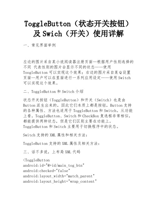
ToggleButton(状态开关按钮)及Swich(开关)使用详解一、常见界面举例左边的图片采自某小说阅读器注册页面—根据用户性别选择的不同代表性别的图片会显示不同的状态——使用ToogleButton可以实现这个效果;右边的图片采自某Q设置页面—用户可以在里面进行一系列应用设定——使用Switch 可以实现这个效果。
二、ToggleButton和Switch介绍状态开关按钮(ToggleButton)和开关(Switch)也是由Button派生出来的,因此它们本质上都是按钮,Button支持的各种属性、方法也适用于ToggleButton和Switch。
从功能上看,ToggleButton、Switch和CheckBox复选框非常相似,都能提供两种状态,但是它们区别主要在功能上。
ToggleButton和Switch主要用于切换程序中的状态。
Switch支持的XML属性和相关方法:ToggleButton支持的XML属性及相关方法:三、话不多说,上布局XML代码<ToggleButtonandroid:id="@+id/main_tog_btn"android:checked="false"android:layout_width="match_parent"android:layout_height="wrap_content"android:textOn="open"android:textOff="close"/><ImageViewandroid:id="@+id/main_img"android:layout_marginTop="50dp"android:layout_width="match_parent"android:layout_height="wrap_content"android:src="@drawable/circle_red"/><Switchandroid:layout_marginTop="100dp"android:layout_gravity="center"android:switchMinWidth="200dp"android:splitTrack="true"android:id="@+id/main_sw"android:layout_width="wrap_content"android:layout_height="wrap_content"android:textOff="low"android:textOn="speed"android:thumb="@drawable/close"android:checked="false"android:text="我是Switch"/>布局XML代码中一共布局了一个ToggleButton、一个Switch、一个测试用的ImageView。
matlab simscape switch用法
matlab simscape switch用法在Matlab中,使用Simscape进行建模和仿真时,可以使用Switch组件将电路分流为两个或多个不同的路径。
Switch组件根据输入变量的值选择激活或禁用不同的输出路径。
Switch组件的基本语法如下:```matlabswitch(condition)case value1% 分支1的操作case value2% 分支2的操作case value3% 分支3的操作...otherwise% 默认分支的操作end```其中,`condition`是用来判断选择哪个分支的变量或表达式,`value1`、`value2`等是与条件值匹配的选项,`otherwise`是当条件值不匹配任何选项时执行的默认分支。
在Simscape中,Switch组件可以用来模拟开关,通过条件值的变化来切换不同的路径。
例如,可以使用Switch组件模拟电路中的开关控制电机的启停。
下面是一个使用Switch组件的例子:```matlabmodel = createpde(1);switchCase = [1, 2, 3];switchValue = 2;switch switchValuecase 1t = 'option1';case 2t = 'option2';case 3t = 'option3';otherwiset = 'default option';enddisp(t);```在这个例子中,`switchValue`的值为2,根据不同的条件值选择了`case 2`的分支,所以输出结果为`option2`。
在Simscape中使用Switch组件时,可以根据具体的模型和需求来选择不同的条件和分支操作。
例如,根据传感器的测量值切换控制器的行为,或者根据电池的充电状态切换充电电路的连接方式等等。
具体的用法可以根据具体的情况灵活使用。
Bootstrap开关(switch)控件学习笔记分享
Bootstrap开关(switch)控件学习笔记分享bootstrap-switch插件是⼀个针对Bootstrap实现的开关(switch)按钮控件,可以⽀持尺⼨、颜⾊等属性的⾃定义。
开关式按钮在国内⽹站上使⽤的并不是很多,Bootstrap 的应⽤在国外⾮常流⾏,不知道是我们不喜欢还是使⽤它很⿇烦很难适合⽹站来使⽤。
但这种开头式按钮在⼿机等移动设备上的应⽤是最⼴泛的,屏幕的特性促使它更好的发展。
功能说明:介绍chekbox与radio的两个表单的简单使⽤,其他更多的效果与功能可以浏览demo,点击按钮以滑动的⽅式进⾏on/off切换。
使⽤说明:1.引⼊CSS与JS⽂件<link rel="stylesheet" href="static/stylesheets/bootstrap-switch.css" /><script src="/ajax/libs/jquery/1.9.1/jquery.min.js"></script><script src="static/js/bootstrap-switch.js"></script>2.html内容添加<div class="make-switch" data-on="info" data-off="success"><input type="checkbox" checked></div><div class="make-switch" data-on="success" data-off="warning"><input type="checkbox" checked></div><div class="make-switch" data-on="warning" data-off="danger"><input type="checkbox" checked></div><div class="make-switch" data-on="danger" data-off="default"><input type="checkbox" checked></div><div class="make-switch" data-on="default" data-off="primary"><input type="checkbox" checked></div>1). div完全是为了给checkbox添加式样。
- 1、下载文档前请自行甄别文档内容的完整性,平台不提供额外的编辑、内容补充、找答案等附加服务。
- 2、"仅部分预览"的文档,不可在线预览部分如存在完整性等问题,可反馈申请退款(可完整预览的文档不适用该条件!)。
- 3、如文档侵犯您的权益,请联系客服反馈,我们会尽快为您处理(人工客服工作时间:9:00-18:30)。
常用开关说明
2:控制Cut Piece(切管)是否输出及格式:
――是否输出列表
――切管编号表现形式,是字母还是数字,由程序自
动生成。
――图面上切管编号的方框形式
4:设置图面上由ISOGEN生成的文字字体及大小。
――指定文字的大小
――指定是否使用自定义字体及字体名
6:设置标题栏日期的格式和来源。
――日期输出格式
――日期来源
――日期格式:使用两位还是四位,即81或1981 7:设置强制分割图纸的张数及是否忽略用户自定义的图纸断点
――分图比例张数(如果输入0,则表示自动分割,
否则输入的数据就是单根管线出图的张数)
――是否忽略用户自定义的图纸断点
9:设置标注格式:
――支撑的标注形式
――垫片的标注形式
――文字与标注线位置关系:中间或上方
――是否显示余量:当要显示带余量的焊点时要打开。
――是否将管道与弯头的标注合并
10,11,12,13:这四个开关是用来设置画图区的四个边框距离图框的四边的距离。
14:是用来选择用多大的图纸出图的。
如果你选择了A3图纸出图,那么你的图框在Project Manger也要选A3的图框。
17:设置是否在管件上显示流向箭头
19/20:坡度管线标示(是以角度的形式显示还是以百分比的形式表示等等)
21:设置材料表的输出样式。
FABRICATION与ERECTION合并输出;只输出FABRICATION数据;只输出ERECTION数据;只输出材料表,没有图形等。
(FABRICA TION:制造(shop);ERECTION:安装)
22:切管余量值(On-Shore,Off-Shore),例如可以在这设置单管图上的焊接余量值
23:设置材料表的输出格式的。
Special Material List是输出的管件每个都单独统计,不再合并在一起。
Normal Material List with Alpha pointer是指输出的材料表的PT-NO用字母来统计。
也可以不输出材料表。
――开关材料表
――材料表类型
――材料表样式:共有4种样式
――是否使用自定义材料表文件
――带有材料分类名和材料分组名,并带有分割线
――没有材料分类名和材料分组名
――没有材料分类名和材料分组名,但无分割线
24:设置当同一管线号被分成多张单管图输出时,材料表是按单管图分图纸生成还是整个线号生成一个材料表及其显示的精度
――按单管图分图纸生成材料表 ――按整个管线号生成一个材料表 ――显示精度
25:设置材料表和标题的位置。
――材料表显示在左边 ――材料表显示在右边 ――标题栏显示在右下角 ――标题栏在材料表下面 ――不显示标题栏
26:控制描述是否输出,并设置输出的格式。
27:控制材料表输出的字体的大小。
28:控制材料表上Item Code 的长度。
30:是用来控制当一个图纸被分割为几部分时,材料表是如何显示分配的。
还有要不要显示DRG 。
材料表可以自动显示为两列,也可以显示到下一张图里,但只有材料表没有图形。
DRG 显示是指在只有一张图纸时要不要显示DRG ,如果分为多张图纸,系统强制显示DRG 1 OF 1。
――有一张图纸上只有多出的材料表,而没有图形 ――自动将管道断开,每张单管图上都有图形和材料表(推荐使用)
――多出的图纸上没有图形只有多出的材料表,而且图纸张数显示为1A (不推荐使用)
――如果一个线号只有一张ISO ,则控制要不要显示DRG 1 OF 1;如果有多张ISO ,则强制显示
31:
――下一次出的ISO 图在前一次的基础上累加 ――下一次出的IS O图自动覆盖原有的
32/34 :图形输出比例
――整个ISO 图的比例 ――图形部分的比例
38:是控制每张图纸能够容纳的内容的多少。
把它调大了,一张图纸被分割的分图纸就越少了。
复选框的作用在于:ISO图上的信息内容要不要带上管线号
例如:表示连接性时:是显示Cont.From DRG1, 还是显示Cont.From 1001 DRG1(其中1001为管线号)
39:是控制Spool ID的
――以数字形式显示
――以字母形式显示
――每张新图纸上的Spool ID号依次递增
――每张新图纸上的Spool ID都从1开始
――直接显示为Spool ID
――如果没有用户ID的话显示管线号
――如果没有用户ID的话显示文件名
40.控制支撑Support的输出
41:是关于尺寸控制信息的一些定义。
管径和管长是可以选择输出单位的。
还有系统定义了许多格式。
42:是用来控制北向标的方向和是否包含一个方框。
53/54/75/77/78:用来控制焊点的输出
61:是用来控制保温层在单管图上的显示情况,可以在整个管路(管线,管件)上显示,也可以只在管线上显示,或者不显示保温层。
62:是用来控制伴热在单管图上的显示情况,可以在整个管路(管线,管件)上显示,也可以只在管线上显示,或者不显示保温层。
65:用来设置螺栓长度和管径的输出单位的,和要不要输出在材料表里。
71:是用来设置出图格式。
(DWG、DXF、DGN…….)
73:是用来控制Part Number下面附属框的字符多少和形状的,有三种风格。
76:是用来控制Part Number本身的框能容纳的字符和它的形状以及是否显示Part Number
80:是用来控制标注时是否标注到部件的中心
82:是用来控制重量和重心的计算
92:表示DXF文件是用英制还是公制表示。
注意如果图签是用英制表示的,那么我们应选择英制表示图形。
如果图签是用公制表示的,那么我们应选择公制表示图形。
112:是用来控制流向箭头在管线上的尺寸和开关。
118:用来控制是否在图上标注总体尺寸的及总体尺寸的形式
119:竖直标注样式
121:打孔的主路和分支是如何控制管件和管线的尺寸标注的。
122:控制开孔分支处是否显示坐标。
123:仪表位号格式。
