HPX系列压力传感器
Honeywell ASDX系列 压力传感器 说明书
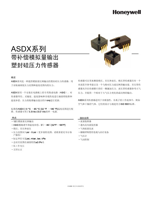
·低工作电压·无铅认证ASDX ㋏߫ᏺ㸹ٓᢳ䞣䕧ߎลᇕ⸙य़Ӵᛳ఼ὖ䗄ASDX ㋏߫ᰃϔ⾡ᦤկᢳ䞣↨՟䕧ߎⱘลᇕ⸙य़Ӵᛳ఼ˈ⫼Ѣ䇏প⒵ࠏᑺय़㣗ೈ⏽ᑺ㣗ೈݙⱘय़DŽASDX Փ⫼ϔϾᅝ㺙⬉䏃ᵓϞⱘϧ⫼䲚៤⬉䏃˄ASIC ˅ˈᇍӴᛳ఼䳊ԡǃ♉ᬣᑺǃ⏽ᑺᕅડ䴲㒓ᗻᑺ䖯㸠⒵䞣᷵ޚ⏽ᑺ㸹ٓDŽय़ⱘ᷵ޚ䕧ߎؐҹ㑺1 kHz 䖯㸠ᮄDŽᷛޚⱘASDX 0 °C ̚85 °C [32 °F ̚185 °F]⏽ᑺ㣗ೈ䖯㸠᷵ޚDŽӴᛳ఼ৃ⫼Ѣ3.3Vdc 5.0 Vdc ⱘऩϔ⬉⑤DŽӴᛳ఼ৃҹ⫼ᴹ⌟䞣㒱य़ǃᏂय़㸼य़DŽ㒱य़ൟӴᛳ఼᳝ϔϾݙ䚼ⳳぎখ㗗ؐҹঞϔϾϢ㒱ᇍय़៤↨՟ⱘ䕧ߎؐDŽᏂय़ൟӴᛳ఼ܕ䆌Ӵᛳ㝰⠛ⱘӏϔջᮑࡴय़DŽ㸼य़ൟӴᛳ఼খ㗗⇨य़ˈᑊᦤկϔϾⳌᇍѢ⇨य़ব࣪ⱘ៤↨՟ⱘ䕧ߎDŽASDX ㋏߫Ӵᛳ఼䗖⫼Ѣ䴲㜤㱔ᗻǃ䴲⾏ᄤⱘᎹ⌕ԧЁˈ՟བぎ⇨ᑆ➹ⱘ⇨ԧDŽᅗӀⱘ䆒䅵Ϣࠊ䗴ヺড়ISO 9001ᷛޚDŽ⡍⚍g 12ԡᢳ䞣↨՟䕧ߎg ASIC ㊒⹂䇗㡖⏽ᑺ㸹ٓ˖0ć̚85ć[32°F ̚185°F] g 㒱य़ǃᏂय़㸼य़g य़㣗ೈҢ1 psi ̚5 psi ˄䞣㣗ೈˈ䇋㘨㋏䳡ሐ䶺ᇨᅶ᠋᳡ࡵ˅g ᷛᅮऩԡৃ䗝psi, mbar, bar, kPa g ᘏ䇃Ꮒ㣗ೈ⒵䞣ⱘ±2.0%ݙ┰ᑨ⫼g ⌕䞣᷵ޚ఼g 䗮亢ঞ亢䞣ⲥ఼g ⇨ԧ⌕䞣Ҿ㸼g ⴵ᱖ذⲥ㾚Ϣ⊏⭫䆒g ⇨य़䅵g ⇨ࡼࠊ© 2009 䳡ሐ䶺ᇨ⠜ᴗ᠔᳝© 2009 霍尼韦尔版权所有2 霍尼韦尔传感与控制部ASDX 系列塑封硅压力传感器表1. 绝压最大额定值1参数最小最大单位供电电压(V 电源)-0.3 6.0V 任意引脚上的电压-0.3V 电源+0.3V ESD 感应(人体模式)3-kV 储存温度-50[-58]125[257]℃ [O F]焊接温度(2s 至4s)-250[482]℃ [O F]V 供电和接地之间的外部电容2100470nF表2. 操作规格参数最小典型最大单位供电电压(V 电源)33.3V 5.0V根据按订货指南选定的型传感器可以是3.3V ,也可以是5.0V(见图1) 3.04.753.345.043.65.25Vdc 供电电流 2.5mA补偿温度范围50[32]-85[185]℃ [O F]工作温度范围6-20[-4]-105[221]℃ [O F]过压72倍工作压力范围以上爆裂压力83倍工作压力范围以上启动时间(电源供应直至数据就绪)--5ms 响应时间-1.0-ms 最高输出限制97.5--%V 电源最低输出限制-- 2.5%V 电源最小负载电阻 5.0--k Ω总误差带9-- 2.0%FSS(满量程)10输出分辨率12--bits表3. 环境规格参数特性湿度0%至95%RH(相对湿度),无凝露振动20Hz 至2000Hz, 10G 冲击100G 持续11ms 寿命最少1百万次压力循环表4. 湿材料11参数端口1(压力端口)端口2(压力端口)密封盖玻璃充填PBT 玻璃充填PBT 粘合剂硅树脂RTV 硅树脂RTV 和环氧电气部件硅树脂和玻璃硅树脂、玻璃和金制品注:1. 绝对最大额定值是装置可以承受而不引起装置损坏的极限。
V2500发动机气源系统中高压活门的故障分析及维护处理
V2500发动机气源系统中高压活门的故障分析及维护处理发布时间:2023-02-01T08:16:22.384Z 来源:《中国科技信息》2022年9月第18期作者:高飞[导读] V2500发动机是国际航空发动机公司(IAE)研制生产的双转子、轴流式高飞四川航空股份有限公司,四川成都 610202摘要:V2500发动机是国际航空发动机公司(IAE)研制生产的双转子、轴流式、高涵道比涡轮风扇发动机。
发动机是整个飞机的心脏,其运行状态关系整个航空器的安全运行,而发动机气源系统又与客舱增压及调温系统紧密相连,关乎着飞机上每一名旅客的生命安全。
本文以配备V2500发动机的A320CEO系列飞机为例,对发动机气源系统中高压活门故障进行分析,并提出了相应的维护建议。
关键词:V2500发动机;气源系统;高压活门1.飞机气源系统简介气源系统内输送高压空气,用于空调、大翼防冰保护、水箱增压、液压油箱增压、发动机启动及燃油油箱惰性气体系统。
气源系统主要由两台气源监控计算机(BMC1和BMC2)控制和监控。
每台气源监控计算机控制各自的发动机气源系统,两台气源监控计算机相互交互数据。
2.发动机气源系统工作原理发动机气源被调压和调温后供应到气源系统,发动机气源来自发动机压气机的高压级(HP)和中间级(IP),当发动机在低功率时候,HPV供应空气到气源系统;当IP级的气源充足时候,HPV关闭。
所有发动机的气源通过压力调节活门(PRV,有关断和调节功能)后供应到气源系统。
3.发动机气源系统部件简介发动机气源系统的主要部件有:压力调节活门(PRV)、高压活门(HPV)、中间级活门(IPV)、过压活门(OPV),转换压力传感器(7HA)、调节压力传感器(8HA)、PRV控制电磁阀(10HA)、HPV控制电磁阀(4029KS)、senseline、风扇空气活门(FA V)、预冷器、FA V控制恒温阀(7170HM)及温度传感器(6HA1或6HA2)。
一种耐高压光纤布拉格光栅压力传感器
维普资讯
第3 6卷 第 6期
20 06年 6月
激 光 与 红 外
LA E & I RAR S R NF ED
Vo . 6. o 6 13 N .
J n .O 6 u e20
文章编号 :0 157 (0 6 0 -4 50 10 -0 8 2 0 )60 9 -3
T e r lt n hp b t e n t e p e s r n e c nr v ln t f B i d rv d h eai s i ew e h r su ea d t e t wa ee gh o G e e .An ea ayi x r s in i - o h l a F s i d t n tce p e so a h l sl
的压力响应具有很好 的线性, 压力测量范围可达 3M a以上。可应用于高压情况下物理量的 0P
传 感测 量 。
关键词 : 光纤布拉格光栅 ; 压力传感器 ; 耐高压 中图分类号:N 5 T 23 文献标识码 : A
A b r Gr tn e s r e s r 、 h ih Pr su e r ssa c Fi e a i g Pr su e S n o t H g e s r ・e it n e
S i n h rs r snivy( .6 6 m MP )o esno ece o x e m n.I i2 ie fh t Og e .T epes e es it 0 07 n / a fh esr s ah df m ep r et ts 3t s a v u ti t ir r i m o t
JUMO MIDAS C08 OEM 压力传感器 数据表 401002说明书
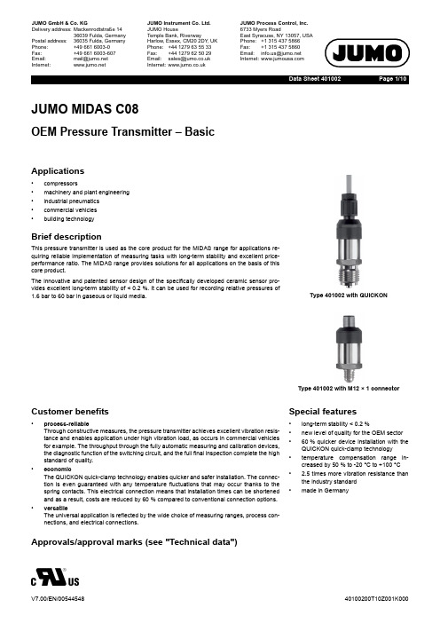
Page 1/10Data Sheet 401002JUMO MIDAS C08OEM Pressure Transmitter – BasicApplications•compressors•machinery and plant engineering •industrial pneumatics •commercial vehicles •building technologyBrief descriptionThis pressure transmitter is used as the core product for the MIDAS range for applications re-quiring reliable implementation of measuring tasks with long-term stability and excellent price-performance ratio. The MIDAS range provides solutions for all applications on the basis of this core product.The innovative and patented sensor design of the specifically developed ceramic sensor pro-vides excellent long-term stability of <0.2%. It can be used for recording relative pressures of 1.6bar to 60bar in gaseous or liquid media.Type 401002 with QUICKONType 401002 with M12×1 connectorCustomer benefits•process-reliableThrough constructive measures, the pressure transmitter achieves excellent vibration resis-tance and enables application under high vibration load, as occurs in commercial vehicles for example. The throughput through the fully automatic measuring and calibration devices,the diagnostic function of the switching circuit, and the full final inspection complete the high standard of quality.•economicThe QUICKON quick-clamp technology enables quicker and safer installation. The connec-tion is even guaranteed with any temperature fluctuations that may occur thanks to the spring contacts. This electrical connection means that installation times can be shortened and as a result, costs are reduced by 60 % compared to conventional connection options.•versatileThe universal application is reflected by the wide choice of measuring ranges, process con-nections, and electrical connections.Special features•long-term stability <0.2%•new level of quality for the OEM sector •60% quicker device installation with the QUICKON quick-clamp technology •temperature compensation range in-creased by 50 % to -20°C to +100°C • 2.5 times more vibration resistance than the industry standard •made in GermanyApprovals/approval marks (see "Technical data")Page 2/10Data Sheet 401002Technical dataGeneral InformationMeasuring range and accuracyReference conditions DIN 16086 and DIN EN 60770SensorMeasuring principle Thick film on ceramic bodies (piezo-resistive)Admissible load changes >10million, 0to 100% measuring range Mounting position AnyCalibration positionDevice upright, process connection at the bottom Measuring rangeLinearity a Accuracy at Long-term stability b Overload capacity c Burst pressure 20°C d -10to +85°C e -20to +100°C e % MSP f% MSP % MSP % MSP % MSP per year bar bar 0to 1.6bar relative pressure 0.250.50.6510.26120to 2.5bar relative pressure 6120to 4bar relative pressure 0.350.512250to 6bar relative pressure 12250to 10bar relative pressure 20380to 16bar relative pressure 50750to 25bar relative pressure 50750to 40bar relative pressure 1202000to 60bar relative pressure 120200-1to +0.6bar relative pressure 0.50.65612-1to +1.5bar relative pressure 612-1to +3bar relative pressure 0.350.51225-1to +5bar relative pressure 1225-1to +9bar relative pressure 2038-1to +15bar relative pressure 5075-1to +24bar relative pressure5075a Linearity according to limit point settingb Reference conditions EN 61298-1c All pressure transmitters are vacuum-proof.d Includes: linearity, hysteresis, repeatability, deviation of measuring range initial value and measuring range end valuee Includes: linearity, hysteresis, repeatability, deviation of measuring range initial value and measuring range end value, thermal effect on mea-suring range start and measuring span fMSP = Measuring spanPage 3/10Data Sheet 401002OutputMechanical featuresAnalog output a Current 4to 20mA, two-wire (output 405)VoltageDC 0.5to 4.5V, three-wire,ratiometric 10to 90% of the voltage supply (output 412)DC 0to 10V, three-wire (output 415)DC 1to 5V, three-wire (output 418)DC 1to 6V, three-wire (output 420)Step response T 90≤2msBurden CurrentR L ≤(U B -8V)÷0.02A (Ω) at 4to 20mA, two-wire (output 405)Voltage(burden connected to "0V/S-")R L ≥5k Ω at DC 0.5to 4.5V, three-wire (output 412)R L ≥10k Ω at DC 0to 10V, three-wire (output 415)R L ≥10k Ω at DC 1to 5V, three-wire (output 418)R L ≥10k Ω at DC 1to 6V, three-wire (output 420)aFurther outputs are available upon request.MaterialProcess connection Stainless steel 304for push-in fitting(process connection 383)Brass, nickel-plated Seal 600 (internal a )EPDM Seal 601 (internal a)FKM, standard Seal 602 (internal a )CR Seal 604 (internal a )FFKM Seal 609 (internal a )NBR for G 1/4 (process connection 521)(external a )FKMSensor Ceramic Al 2O 3 96%HousingStainless steel 304Attached cable(electrical connection 11)PBT-GF30, PVC QUICKON(electrical connection 23)PBT-GF30Round plug M12×1 (electrical connection 36)PBT-GF30, stainless steel 303L Bayonet connector(electrical connection 53)PBT-GF30Cable socket(electrical connection 61)PBT-GF30, PA, siliconeWeight70g with G 1/4 (process connection 502)aEnsure the medium durability of the seal material!Page 4/10Data Sheet 401002Environmental influencesMedium temperature for electrical connection Attached cable -20to +125°C Round plug M12×1-20to +125°C Bayonet connector -20to +125°C Cable socket -20to +125°CAmbient temperature for electrical connection Attached cable-20to +100°CAt ambient temperature of -30°C restricted function. Only use when stationary. Risk of cable break.Round plug M12×1-20to +100°C Bayonet connector -20to +100°C Cable socket -20to +100°C Storage temperature for electrical connection Attached cable -30to +100°C Round plug M12×1-40to +100°C Bayonet connector -40to +100°C Cable socket -40to +100°CAdmissible humidity Operation 100% rel. humidity including condensation on the device outer case Storage90% rel. humidity without condensationAdmissible mechanical load Vibration resistance 50g for 10to 2000Hz, according to IEC 60068-2-6Shock resistance50g for 3ms, 100g for 2ms, according to IEC 60068-2-27Electromagnetic compatibility according to EN 61326-2-3Interference emission Class B aInterference immunity Industrial requirement Protection typefor electrical connection according to EN 60529Attached cable IP67QUICKON b IP67Round plug M12×1cIP67Bayonet connector c IP67Cable socket c, dIP65a The product is suitable for industrial use as well as for households and small businesses.b Connecting cable diameter, minimum 3.5mm, maximum 6mmc The protection type is only achieved with a suitable mounted counter piece.dConnecting cable diameter, minimum 6mm, maximum 8mmPage 5/10Data Sheet 401002Auxiliary powerApprovals/approval marksVoltage supply U B a4to 20mA, two-wire (output 405)DC 8to 30V, rated voltage supply DC 24V DC 0.5to 4.5V, three-wire (output 412)DC 3to 5.25V, rated voltage supply DC 5V,ratiometric output 10to 90% of the voltage supply DC 0to 10V, three-wire (output 415)DC 11.5to 30V, rated voltage supply DC 24V DC 1to 5V, three-wire (output 418)DC 8to 30V, rated voltage supply DC 24V DC 1to 6V, three-wire (output 420)DC 8to 30V, rated voltage supply DC 24V Current consumption incl. load 4to 20mA, two-wire (output 405)≤25mA DC 0.5to 4.5V, three-wire (output 412)≤3mA DC 0to 10V, three-wire (output 415)≤3mA DC 1to 5V, three-wire (output 418)≤3mA DC 1to 6V, three-wire (output 420)≤3mA Reverse voltage protection Yes Electrical circuit SELVRequirementsThe device must be equipped with an electrical circuit that meets the requirements of EN 61010-1 with regardto "Limited-energy circuits".aResidual ripple: the voltage peaks must not exceed or fall below the specified voltage supply values!Approval mark Testing agency Certificate/certification num-ber Inspection basisValid forc UL usUnderwriters LaboratoriesE201387UL 61010-1 (3. Ed.),CAN/CSA-22.2No.61010-1(3. Ed.)Only in connection with extra code 061;observe order detailsPage 6/10Data Sheet 401002DimensionsElectrical connectionPage 7/10Data Sheet 401002Process connectionØ8mm*Extra code 630 pressure channel Ø8mmPage 8/10Data Sheet 401002Connection diagramThe connection diagram in the data sheet provides preliminary information about the connection options. For the electrical connection, only use the installation instructions or the operating manual. The knowledge and the correct technical compliance with the safety information and warnings contained in these documents are mandatory for mounting, electrical connection, and startup as well as for safety during operation.Cable socketnection.Color coding: connecting cable round plug M12×11 BN Brown2 WH White3 BU Blue4 BKBlackThe color coding is only valid for A-coded standard cables!Page 9/10Data Sheet 401002Order details(1)Basic type401002/000JUMO MIDAS C08 – OEM pressure transmitter – basic401002/999JUMO MIDAS C08 – OEM pressure transmitter – basic, special version (2)Input4550to 1.6bar relative pressure 4560to 2.5bar relative pressure 4570to 4bar relative pressure 4580to 6bar relative pressure 4590to 10bar relative pressure 4600to 16bar relative pressure 4610to 25bar relative pressure 4620to 40bar relative pressure 4630to 60bar relative pressure 479-1to +0.6bar relative pressure 480-1to +1.5bar relative pressure 481-1to +3bar relative pressure 482-1to +5bar relative pressure 483-1to +9bar relative pressure 484-1to +15bar relative pressure 485-1to +24bar relative pressure999Special measuring range for relative pressure (3)Output4054to 20mA, two-wire4120. 5to 4.5V, three-wire, ratiometric 4150to 10V, three-wire 4181to 5V, three-wire 4201to 6V, three-wire (4)Process connection383Push-in fitting for pipe/hose 6×4DN 6502G 1/4 DIN EN 837504G 1/2 DIN EN 8375111/4-18 NPT DIN EN 837521G 1/4 DIN 547Rp 1/8 inside 5627/16-20 UNF(5)Process connection material 20CrNi (stainless steel)(6)Material seal 600EPDM 601FKM a 602CR 604FFKM 609NBR999Special materialPage 10/10Data Sheet 401002Accessories(7)Electrical connection 11Attached cable b 23Quickon36Round plug M12×153Bayonet connector DIN 7258561Cable socket DIN EN 175301-803, Form A (8)Extra codes 000None 061UL approval c591Choke in the pressure channel 624Oil and grease free 630Enlarged pressure channel d 876Test reporta Standardb The standard cable length is 2m. Further lengths are available upon request.c The UL approval stipulates use of the pressure transmitter indoors. In addition, process connection 383 as well as seals 609 and 999 are not possible. Special measuring ranges (input) are not allowed to exceed the 60 bar limit.dAn enlarged pressure channel of diameter Ø8mm is only available with process connection 1/4-18 NPT (process connection 511), G 1/4 (pro-cess connection 521) and the seal FKM (seal material 601).(1)(2)(3)(4)(5)(6)(7)(8)Order code ------/ , ...aOrder example401002/000-460-412-504-20-600-36/591aList extra codes in sequence, separated by commas.Minimum order volume for manufacturing devices: 5 pieces Minimum order volume for warehouse devices:1 pieceItemDescriptionPart no.Cable box, straightThe PVC connecting cable is 2m in length and has a 4-pin, straight M12×1 connector with gold-plated contacts on the device side.00404585Cable box, angledThe PVC connecting cable is 2m in length and has a 4-pin, angled M12×1 connector with gold-plated contacts on the device side.00409334。
压力传感器 说明书
Gems Sensors & Controls压力传感器压力压力压力传感器压力压力传感器压力压力传感器压力压力传感器认证 ListedDIN配对连接器DIN配对压力压力传感器压力压力传感器压力压力传感器劳埃德船级社压力压力传感器 6插脚固定插头(10-6)符合DIN43650标准的固定插头,提供配对连接器电气连接器M12×1(5插脚)可潜水深度达200m WG(水柱压力)AMP Superseal 1.5DIN 43650C 工业型DIN 72585 卡口M12系列范围德国标准 DTD4-4PPackard Metri-packwith 37° FlareO-Ring代码 OL M12 x 15代码 05G 1/4”A Integral Face Seal代码 2T M12x1.5 HP [metal washer seal]代码 1G 7/16”Schraeder六角尺寸为22mm 其他螺纹请咨询工厂714712.811.1714.44712.510712.511712.511716.5711719.3压力压力传感器DIN43650C IndustrialM12 ×1PDeutsch DT04-4PDIN72585A1-4, 1Packard MetriPackAmp Superseal 1.513241234KEY 12341234KEYABC123619.318.39.7M12×1P38.123.532.2371.920.833725.9Pin #输出类型电流电压1N/A Press O/P+VE 2+VE Supply +VE Temp O/P Pin #输出类型电流电压1+VE Supply +VE 2N/A Press O/P+VE 3-VE Common Pin #输出类型电流电压1+VE Supply +VE 2-VE Common 3N/A Press O/P+VE Pin #输出类型电流电压1-VE Common 2+VE Supply +VE 3N/A Temp O/P +VE Pin #输出类型电流电压A -VE Common B +VE Supply +VE CN/APress O/P+VEPin #输出类型电流电压1N/A Press O/P+VE 2-VE Common 3+VESupply +VEAMP Superseal 1.5DIN 43650C 工业型DIN 72585 卡口M12系列范围德国标准 DTD4-4PPackard Metri-packwith 37° FlareO-Ring六角尺寸为22mm 其他螺纹请咨询工厂714712.811.1714.44719.3712.511代码 OL M12 x 15代码 05G 1/4”A Integral Face Seal712.510712.511压力压力传感器DIN43650C IndustrialM12 ×1PDeutsch DT04-4PDIN72585A1-4, 1Packard MetriPackAmp Superseal 1.513241234KEY 12341234KEYABC123619.318.39.7M12×1P38.123.532.2371.920.833725.9Pin #输出类型电流电压1N/A Press O/P+VE 2+VE Supply +VE Temp O/P Pin #输出类型电流电压1+VE Supply +VE 2N/A Press O/P+VE 3-VE Common Pin #输出类型电流电压1+VE Supply +VE 2-VE Common 3N/A Press O/P+VE Pin #输出类型电流电压1-VE Common 2+VE Supply +VE 3N/A Temp O/P +VE Pin #输出类型电流电压A -VE Common B +VE Supply +VE CN/APress O/P+VEPin #输出类型电流电压1N/A Press O/P+VE 2-VE Common 3+VESupply +VE外形尺寸(mm)压力压力传感器外形尺寸(mm)压力压力传感器压力压力传感器劳埃德船级社10315981/2-1/4NPT 导管6插脚固定插头规格(10-6)DIN43650固定插头,提供配对插头5插脚M12x1固定插头投入式IP68,可达200m WG 代码3代码代码代码代码压力压力传感器压力压力传感器压力压力传感器压力压力传感器压力压力传感器压力压力传感器压力压力传感器DIN 436505插脚投入式IP68,最大深度可达压力压力传感器外形尺寸(mm)150.017.0板手平面Ф19.0屏蔽线通风管压力压力传感器外形尺寸(mm)外形尺寸(mm)压力压力传感器防污染盖G1/2 电缆安装接头带限压器的鼻锥 型号555825-0003沉锤鼻锥 型号562685-02后安装沉锤(需要5 只)Nickle Plated Brass Cable GlandG 1/2 Thread35.028.6 A/F Hex137106ø27.2ø10 Through HoleG 1/8 Ext Thread146ø20ø5G 1/4 THREAD135ø18.60ø2537.501604363120108Side ASide CSide B压力外形尺寸(mm)5482B型: 电压输出红 激励电压 12 - 24Vdc白 输出 4 - 20mA屏蔽 (24V AC/DC白 输出 0 - 10V黑 - 公共端屏蔽 (2 x Ø4.20(32.0)(22.00)4.0G1/8(TYP.)14.0 A/F(TYP.)Ø44.5Ø40.019.030.012(12.7)(23.7)墙上固定支架14.0。
LPS33HW微型压力传感器
【 _ 常 生 活 , 佩 戴 青 希 能 够 戴 着 这 些 设 符 跟 踪 游 泳 等 彩的活 动 情 况 。 一 - j : 1 . 的 新 一 代运动手环 G e a r F i t 2 P r o
他 顺 应 了 这 一 趋 协 , 它 成 _ 厂内置 GP S 、 连 续 心
境的f J1仪 问 仃 比 【 1 . ’ 光 了 更 多 的 近
此 伎 Ny x e l 技术_ I j ’ 以 在 伎 间 进 行 f 彰托 的 L E D 灯 ,从 而
测 , 以 及 更 人 的 储
, 以 支 持 手
没 仃 连 接 智
能 r机 时 继 续 运 行 所 喽 的 功 能 。 意 法 导 体 I ' l " J 新 款 防 水压力 传感 器 L P S 3 3 H W 是 Ge a r F i t 2 P r o L { l I } 常暄
r
川 川1 ' i  ̄ 3 & 纹 理 , 以 保 持 制 传 递 数 , 并 不 影 响
化 感 的 I U 流 。 使 川 夜 鹰 Ny x e l t 科 技 的 产 品 与 使 J } J 一 祭贼 披 O mn i Vi s i o n的 传 统 近 外 , , : f t 卡 u 比,
P r o d u c t E x p r e s s I 精品推介
r 1 = 十 l l f , l J 血 外 光 F成 像 消 晰 , 远 ;并且可 以 拎 删 远 的 成 像 域 。 川叫‘ , 为 J 配 日前 系 统 的 意法 半 导 体 发 丫微 压 力 传 感 器 L P S 3 3 H W ,将 / 1 i 乃传 感 器 水 卜 精 度 推 J 新高度 ,这款 J 『 l t 2 』 、
MPX5010-压力传感器

MPX5010Rev 11, 01/2007Freescale Semiconductor Technical Data© Freescale Semiconductor, Inc., 2007. All rights reserved.Integrated Silicon Pressure Sensor On-Chip Signal Conditioned, Temperature Compensated and CalibratedThe MPX5010/MPXV5010G series piezoresistive transducers are state-of-the-art monolithic silicon pressure sensors designed for a wide range of applications, but particularly those employing a microcontroller or microprocessor with A/D inputs. This transducer combines advancedmicromachining techniques, thin-film metallization, and bipolar processing to provide an accurate, high level analog output signal that is proportional to the applied pressure.Features• 5.0% Maximum Error over 0° to 85°C•Ideally Suited for Microprocessor or Microcontroller-Based Systems•Durable Epoxy Unibody and Thermoplastic (PPS) Surface Mount Package •Temperature Compensated over –40° to +125°C •Patented Silicon Shear Stress Strain Gauge•Available in Differential and Gauge Configurations•Available in Surface Mount (SMT) or Through-hole (DIP) Configurations Application Examples •Hospital Beds •HVAC•Respiratory Systems •Process ControlORDERING INFORMATIONDevice Type Options Case No.MPX Series Order No.Packing Options Device Marking SMALL OUTLINE PACKAGE (MPXV5010G SERIES)Basic Elements Gauge, Element Only, SMT 482MPXV5010G6U Rails MPXV5010G Gauge, Element Only, DIP 482B MPXV5010G7U Rails MPXV5010G Ported Elements Gauge, Axial Port, SMT 482A MPXV5010GC6U Rails MPXV5010G Gauge, Axial Port, DIP 482C MPXV5010GC7U Rails MPXV5010GGauge, Axial Port, SMT 482A MPXV5010GC6T1Tape & ReelMPXV5010GGauge, Side Port, SMT 1369MPXV5010GP Trays MPXV5010G Gauge, Dual Port, SMT 1351MPXV5010DP Trays MPXV5010GUNIBODY PACKAGE (MPX2202 SERIES)Basic ElementDifferential 867MPX5010D —MPXV5010D Ported Elements Differential, Gauge 867C MPX5010DP —MPXV5010DP Gauge 867B MPX5010GP —MPXV5010GPGauge, Axial 867E MPX5010GS —MPXV5010D Gauge, Axial PC Mount 867F MPX5010GSX —MPXV5010DMPX5010MPXV5010G SERIESUNIBODY PACKAGE PIN NUMBERS (1)1.Pins 4, 5, and 6 are internal device connections. Do not connect to external circuitry or ground. Pin 1 is noted by the notch in the lead.1V out 4N/C 2Gnd 5N/C 3V S6N/CSMALL OUTLINE PACKAGEPIN NUMBERS (1)1.Pins 1, 5, 6, 7, and 8 are internal deviceconnections. Do not connect to external circuitry or ground. Pin 1 is noted by the notch in the lead.1N/C 5N/C 2V S 6N/C 3Gnd 7N/C 4V out8N/CMPX5010SensorsFigure 1. Fully Integrated Pressure Sensor SchematicSensing ElementThin Film Temperature Compensationand Gain Stage #1Gain Stage #2and Ground Reference Shift CircuitryV SV outGNDPins 1 and 5 through 8 are NO CONNECTS for surface mount packagePins 4, 5, and 6 are NO CONNECTS for unibody packageTable 1. Maximum Ratings (1)1.Exposure beyond the specified limits may cause permanent damage or degradation to the device.RatingSymbol Value Unit Maximum Pressure (P1 > P2)P max 75kPa Storage Temperature T stg –40 to +125°C Operating TemperatureT A–40 to +125°CMPX5010SensorsTable 2. Operating Characteristics (V S = 5.0 Vdc, T A = 25°C unless otherwise noted, P1 > P2. Decoupling circuit shown in Figure 3 required to meet specification.)CharacteristicSymbol Min Typ Max Unit Pressure Range (1)1. 1.0 kPa (kiloPascal) equals 0.145 psi.P OP 0—10kPa Supply Voltage (2)2.Device is ratiometric within this specified excitation range.V S 4.75 5.0 5.25Vdc Supply CurrentI o — 5.010mAdc Minimum Pressure Offset (3)(0 to 85°C)@ V S = 5.0 Volts 3.Offset (V off ) is defined as the output voltage at the minimum rated pressure.V off0.20.425VdcFull Scale Output (4)(0 to 85°C)@ V S = 5.0 Volts 4.Full Scale Output (V FSO ) is defined as the output voltage at the maximum or full rated pressure.V FSO4.475 4.7 4.925VdcFull Scale Span (5)(0 to 85°C)@ V S = 5.0 Volts 5.Full Scale Span (V FSS ) is defined as the algebraic difference between the output voltage at full rated pressure and the output voltage at the minimum rated pressure.V FSS4.275 4.5 4.725VdcAccuracy (6)(0 to 85°C)6.Accuracy (error budget) consists of the following:•Linearity:Output deviation from a straight line relationship with pressure over the specified pressure range.•Temperature Hysteresis:Output deviation at any temperature within the operating temperature range, after the temperature is cycled toand from the minimum or maximum operating temperature points, with zero differential pressure applied.•Pressure Hysteresis:Output deviation at any pressure within the specified range, when this pressure is cycled to and from theminimum or maximum rated pressure, at 25°C.•TcSpan:Output deviation over the temperature range of 0° to 85°C, relative to 25°C.•TcOffset:Output deviation with minimum rated pressure applied, over the temperature range of 0° to 85°C, relative to25°C.•Variation from Nominal:T he variation from nominal values, for Offset or Full Scale Span, as a percent of V FSS , at 25°C.———±5.0%V FSS Sensitivity V/P —450—-mV/kPa Response Time (7)7.Response Time is defined as the time for the incremental change in the output to go from 10% to 90% of its final value when subjected to a specified step change in pressure.t R — 1.0—-ms Output Source Current at Full Scale Output I O+—0.1—-mAdc Warm-Up Time (8)8.Warm-up Time is defined as the time required for the product to meet the specified output voltage after the Pressure has been stabilized.——20—-ms Offset Stability (9)9.Offset Stability is the product's output deviation when subjected to 1000 hours of Pulsed Pressure, Temperature Cycling with Bias Test.——±0.5—-%V FSSTable 3. Mechanical CharacteristicsCharacteristicsTyp Unit Weight, Basic Element (Case 867) 4.0grams Weight, Basic Element (Case 482)1.5gramsMPX5010SensorsON-CHIP TEMPERATURE COMPENSATION, CALIBRATION AND SIGNAL CONDITIONINGThe performance over temperature is achieved by integrating the shear-stress strain gauge, temperature compensation, calibration and signal conditioning circuitry onto a single monolithic chip.Figure 2 illustrates the Differential or Gauge configuration in the basic chip carrier (Case 482). A fluorosilicone gel isolates the die surface and wire bonds from the environment, while allowing the pressure signal to be transmitted to the sensor diaphragm.The MPX5010 and MPXV5010G series pressure sensor operating characteristics, and internal reliability andqualification tests are based on use of dry air as the pressure media. Media, other than dry air, may have adverse effects onsensor performance and long-term reliability. Contact the factory for information regarding media compatibility in your application.Figure 3 shows the recommended decoupling circuit for interfacing the integrated sensor to the A/D input of amicroprocessor or microcontroller. Proper decoupling of the power supply is recommended.Figure 4 shows the sensor output signal relative to pressure input. Typical, minimum, and maximum output curves are shown for operation over a temperature range of 0° to 85°C using the decoupling circuit shown in Figure 3. The output will saturate outside of the specified pressure range.Figure 2. Cross-Sectional Diagram SOP(not to scale)Figure 3. Recommended Power Supply Decouplingand Output Filtering(For additional output filtering, please refer toApplication Note AN1646.)Figure 4. Output versus Pressure DifferentialFluoro Silicone Gel Die CoatWire Bond DieP1Stainless Steel CapThermoplasticCaseDie BondDifferential SensingElementP2+5 V1.0 µF0.01 µF470 pFGNDV sV outIPSOUTPUTLead FrameDifferential Pressure (kPa)O u t p u t (V )5.04.54.03.53.02.52.01.51.00.5001234567891110TYPICALMINMAXTransfer Function:V out = V S *(0.09*P+0.04) ± ERROR V S = 5.0 VdcTEMP = 0 to 85°CMPX5010SensorsNominal Transfer Value:V out = V S x (0.09 x P + 0.04)± (Pressure Error x Temp. Factor x 0.09 x V S )V S = 5.0 V ± 0.25 VdcTransfer Function (MPX5010, MPXV5010G)MPX5010, MPXV5010G SERIESTemp Multiplier–4030 to 851+1253Temperature in °C4.03.02.00.01.0–40–2020406014012010080Temperature Error FactorNOTE: The Temperature Multiplier is a linear response from 0° to –40°C and from 85° to 125°C.Temperature Error BandPressure Error (Max)Pressure Error Band0 to 10 (kPa)±0.5 (kPa)Pressure (kPa)0.50.40.2–0.3–0.4–0.501234567890.30.1–0.2–0.110Pressure Error (kPa)MPX5010SensorsPRESSURE (P1)/VACUUM (P2) SIDE IDENTIFICATION TABLEFreescale designates the two sides of the pressure sensor as the Pressure (P1) side and the Vacuum (P2) side. The Pressure (P1) side is the side containing fluorosilicone gel which protects the die from harsh media. The MPX pressuresensor is designed to operate with positive differential pressure applied, P1 > P2.The Pressure (P1) side may be identified by using the table below:MINIMUM RECOMMENDED FOOTPRINT FOR SURFACE MOUNTED APPLICATIONSSurface mount board layout is a critical portion of the total design. The footprint for the surface mount packages must be the correct size to ensure proper solder connection interface between the board and the package. With the correctfootprint, the packages will self align when subjected to a solder reflow process. It is always recommended to design boards with a solder mask layer to avoid bridging and shorting between solder pads.Figure 5. SOP Footprint (Case 482)Part NumberCase TypePressure (P1)Side IdentifierMPX5010D 867Stainless Steel Cap MPX5010DP 867C Side with Part Marking MPX5010GP 867B Side with Port Attached MPX5010GS 867E Side with Port Attached MPX5010GSX 867F Side with Port Attached MPXV5010G6U 482Stainless Steel Cap MPXV5010G7U 482B Stainless Steel Cap MPXV5010GC6U/T1482A Side with Port Attached MPXV5010GC7U 482C Side with Port Attached MPXV5010GP 1369Side with Port Attached MPXV5010DP1351Side with Part Marking0.66016.760.060 TYP 8X 1.520.100 TYP 8X 2.540.100 TYP 8X 2.540.3007.62inch mmSCALE 2:1CASE 482-01ISSUE OSMALL OUTLINE PACKAGECASE 482A-01ISSUE ASMALL OUTLINE PACKAGEMPX5010 SensorsCASE 482B-03ISSUE BSMALL OUTLINE PACKAGECASE 482C-03ISSUE BSMALL OUTLINE PACKAGEMPX5010SensorsCASE 867-08ISSUE NUNIBODY PACKAGEMPX5010 SensorsMPX5010SensorsMPX5010 SensorsCASE 867C-05ISSUE FUNIBODY PACKAGECASE 867E-03ISSUE DUNIBODY PACKAGEMPX5010SensorsCASE 867F-03ISSUE DUNIBODY PACKAGEMPX5010 SensorsMPX5010SensorsMPX5010 SensorsMPX5010SensorsMPX5010 SensorsMPX5010Rev. 11How to Reach Us:Home Page:Web Support:/support USA/Europe or Locations Not Listed:Freescale Semiconductor, Inc.Technical Information Center, EL5162100 East Elliot Road Tempe, Arizona 85284+1-800-521-6274 or +/supportEurope, Middle East, and Africa:Freescale Halbleiter Deutschland GmbH Technical Information Center Schatzbogen 781829 Muenchen, Germany +44 1296 380 456 (English)+46 8 52200080 (English)+49 89 92103 559 (German)+33 1 69 35 48 48 (French)/supportJapan:Freescale Semiconductor Japan Ltd.Headquarters ARCO Tower 15F1-8-1, Shimo-Meguro, Meguro-ku,Tokyo 153-0064Japan0120 191014 or +81 3 5437 9125support.japan@Asia/Pacific:Freescale Semiconductor Hong Kong Ltd.Technical Information Center 2 Dai King StreetTai Po Industrial Estate Tai Po, N.T., Hong Kong +800 2666 8080@For Literature Requests Only:Freescale Semiconductor Literature Distribution Center P .O. Box 5405Denver, Colorado 802171-800-441-2447 or 303-675-2140Fax: 303-675-2150LDCForFreescaleSemiconductor@Information in this document is provided solely to enable system and software implementers to use Freescale Semiconductor products. There are no express or implied copyright licenses granted hereunder to design or fabricate any integrated circuits or integrated circuits based on the information in this document.Freescale Semiconductor reserves the right to make changes without further notice to any products herein. Freescale Semiconductor makes no warranty, representation or guarantee regarding the suitability of its products for any particular purpose, nor does Freescale Semiconductor assume any liability arising out of the application or use of any product or circuit, and specifically disclaims any and all liability, including without limitation consequential or incidental damages. “Typical” parameters that may beprovided in Freescale Semiconductor data sheets and/or specifications can and do vary in different applications and actual performance may vary over time. All operating parameters, including “Typicals”, must be validated for each customer application by customer’s technical experts. Freescale Semiconductor does not convey any license under its patent rights nor the rights of others. Freescale Semiconductor products are not designed, intended, or authorized for use as components in systems intended for surgical implant into the body, or other applications intended to support or sustain life, or for any other application in which the failure of the Freescale Semiconductor product could create a situation where personal injury or death may occur. Should Buyer purchase or use Freescale Semiconductor products for any such unintended orunauthorized application, Buyer shall indemnify and hold Freescale Semiconductor and its officers, employees, subsidiaries, affiliates, and distributors harmless against all claims, costs, damages, and expenses, and reasonable attorney fees arising out of, directly or indirectly, any claim of personal injury or death associated with such unintended or unauthorized use, even if such claim alleges that Freescale Semiconductor was negligent regarding the design or manufacture of the part. Freescale™ and the Freescale logo are trademarks of Freescale Semiconductor, Inc.All other product or service names are the property of their respective owners.© Freescale Semiconductor, Inc. 2007. All rights reserved.。
霍尼韦尔商业开关与传感器说明书
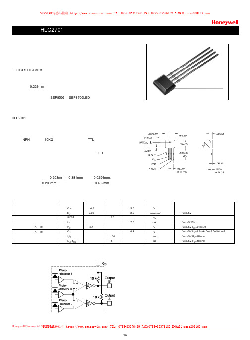
14Honeywell/Commercial Switch&Sensor 霍尼韦尔商业开关与传感器特点侧接收塑料封装TTL/LSTTL/CMOS 兼容反向逻辑输出线性或旋转编码器应用分辨率为0.229mm具有灵敏度温度补偿机械结构上和光谱上与SEP8506和SEP8706LED 相匹配HLC2701专为感测机械运动的速度和方向而设计。
应用包括旋转编码器或线位移编码器。
特别适用于光学鼠标中的编码器。
探测器为单片集成电路包括两个非常靠近的光电二极管、放大器和施密特触发器输出单元。
输出为NPN 集电极带10K Ω上拉电阻,可直接驱动TTL 负载。
探测器中具有灵敏度温度补偿电路,来补偿由于温度变化LED输出功率的漂移。
集成电路封装在一个模压不透光的黑色塑料壳中,可以透射红外能量,而阻挡可见光的透射。
集成电路的敏感区每个宽0.203mm,高0.381mm ,间隔0.0254mm,中心到中心的间隔为0.203mm ,外部边缘到边缘的距离为0.432mm 。
电参数参数供电电压导通辐射阈值迟滞供电电流高电平输出电压(A 和B)低电平输出电压(A 和B)输出上升时间和下降传播延迟,低-高,高-低符号Vcc E eT HYST Icc V OH V OL t r ,t f t PLH , t PHL 最小值 4.5 0.05 2.4典型值 28 100 5最大值 5.5 2.0 7.0 0.4 单位V mW/cm2 % mA V V ns µs 测试条件Vcc=5V Vcc=5.25V Vcc=5V,I OH =0,Ee=0Vcc=5V,I OL =1.6mA,Ee=2.0mW/cm2Vcc=5V,R L =1Kohm Vcc=5V,R L =1Kohm 功能框图外形尺寸图,单位为英寸(毫米)SUNSTAR传感与控制/TEL:0755-********FAX:0755-********E-MAIL:**************SUNSTAR自动化/TEL:0755-********FAX:0755-********E-MAIL:**************公司由传感器销售部、仪表销售部、工程部和总务部四个部组成。
DHP203B,HP206CDEMO使用说明
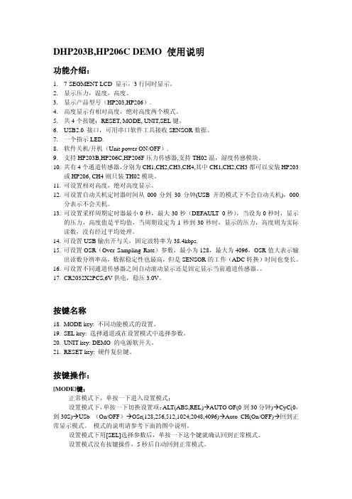
DHP203B,HP206C DEMO 使用说明功能介绍:1.7-SEGMENT LCD 显示,3行同时显示。
2.显示压力,温度,高度。
3.显示产品型号(HP203,HP206).4.高度显示有相对高度,绝对高度两个模式。
5.共4个按键:RESET, MODE, UNIT,SEL键。
B2.0 接口,可用串口软件工具接收SENSOR数据。
7.一个指示LED.8.软件关机/开机(Unit power ON/OFF).9.支持HP203B,HP206C,HP206F压力传感器,支持TH02温,湿度传感模块。
10.共有4个通道传感器,分别为CH1,CH2,CH3,CH4,其中CH1,CH2,CH3都可以安装HP203或HP206, CH4则只装TH02模块。
11.可设置相对高度,绝对高度显示。
12.可设置自动关机定时器时间从000分到30分钟(USB 开的模式下不会自动关机),000分表示不会关机。
13.可设置采样周期定时器最小0秒,最大30秒(DEFAULT 0秒),当设为0秒时,显示的压力,高度值是平均值,当周期设定为1秒到30秒时,显示的压力,高度则为实际读数,没有经过平均处理。
14.可设置USB输出开与关,固定波特率为38.4kbps.15.可设置OSR(Over Sampling Rate)参数,最小为128,最大为4096,OSR值大表示输出读数分辨率高,数据稳定性也最高,但是SENSOR的工作(ADC转换)时间也变长。
16.可设置不同通道传感器之间自动滚动显示还是固定显示当前通道传感器。
17.CR2032X2PCS,6V供电,稳压3.0V。
按键名称18.MODE key: 不同功能模式的设置。
19.SEL key: 选择通道或在设置模式中选择参数。
20.UNIT key: DEMO 的电源软开关。
21.RESET key: 硬件复位键。
按键操作:[MODE]键:---正常模式下,单按一下进入设置模式:---设置模式下,单按一下切换设置项:ALT(ABS,REL)ÆAUTO OF(0到30分钟)ÆCyC(0,到30S)ÆUSb (On/OFF)ÆOSr(128,256,512,1024,2048,4096)ÆAuto CH(On/OFF)Æ回到正常显示模式。
LPS331AP、HP203B精确3D定位感测技术带领智能手机压力传感器进入新的发展阶段

LPS331AP、HP203B精确3D定位感测技术带领智能手机压力传感器进入新的发展阶段手机之所以智能,离不开各种各样的传感器。
现在大多数智能手机都内建了GPS功能,可以让你知道自己在地球表面上的确切位置。
不过,GPS只能告诉你处于什么建筑内,而不能告诉你在这栋建筑物内的准确位置。
要精确的进行室内导航,我们必须在手机里安装更多的传感器。
为此,深圳市惠贻华普电子有限公司(HOPERF)日前开发出一款智能,超小体积,高精度数字传感器HP203B,适合智能的高精度测量和数据采集,输出高精度的压力(或高度)和温度测量数据。
应用非常简单,极大地减少应用的开发周期。
意法半导体(STMicroelectronics,简称ST)和华普(HOPERF),推出能够精确测量手机等便携设备海拔高度的压力传感器,新款传感器的上世意味着移动设备不仅能够识别其所在楼层,还能几乎确定所在楼梯台阶位置。
LPS331AP、HP203B手机压力传感器移动设备的精确定位功能是很多新兴移动定位服务(Location-Based Services,LBS)的关键技术,LBS被业界广泛认为是移动产业下一个杀手级应用。
实现这类新兴服务的挑战是提供立体识别移动设备位置的方法,同时满足各种相互冲突的条件,包括空间分辨率、可靠性和外观尺寸、稳健性和成本。
全球导航卫星系统(Global Navigation Satellite System, GNSS)是平面定位(经纬度)广泛采用的解决方案,当移动设备处于最佳条件,即能够从四颗(或更多颗)卫星接收信号时, 使移动设备的平面位置计算精度达到一米以内。
LPS331AP、HP203B可在无卫星信号条件下确定设备的3D位置。
对于第三维(垂直高度),气压感测技术的分辨率高于GNSS,特别是在卫星能见度少于四颗卫星时,因为气压随着高度上升而稳定下降。
LPS331AP、HP203B新一代压力传感器的量程从260至1260毫巴;260毫巴是大约10千米高度(比珠峰大约高 1,500米)的典型压力;1260毫巴是海平面以下大约1800米深度(大约是世界上最深矿井的二分之一)的典型压力。
HP3、HP4
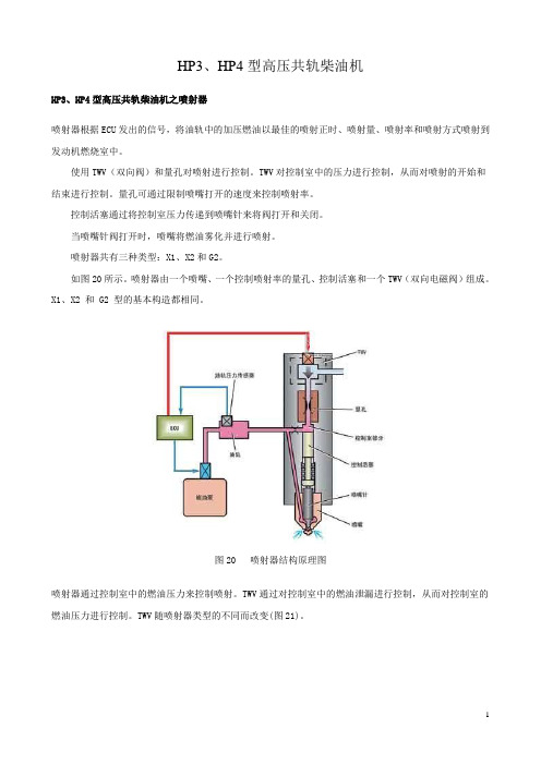
HP3、HP4型高压共轨柴油机HP3、HP4型高压共轨柴油机之喷射器喷射器根据ECU发出的信号,将油轨中的加压燃油以最佳的喷射正时、喷射量、喷射率和喷射方式喷射到发动机燃烧室中。
使用TWV(双向阀)和量孔对喷射进行控制。
TWV对控制室中的压力进行控制,从而对喷射的开始和结束进行控制。
量孔可通过限制喷嘴打开的速度来控制喷射率。
控制活塞通过将控制室压力传递到喷嘴针来将阀打开和关闭。
当喷嘴针阀打开时,喷嘴将燃油雾化并进行喷射。
喷射器共有三种类型:X1、X2和G2。
如图20所示。
喷射器由一个喷嘴、一个控制喷射率的量孔、控制活塞和一个TWV(双向电磁阀)组成。
X1、X2 和 G2 型的基本构造都相同。
图20 喷射器结构原理图喷射器通过控制室中的燃油压力来控制喷射。
TWV通过对控制室中的燃油泄漏进行控制,从而对控制室的燃油压力进行控制。
TWV随喷射器类型的不同而改变(图21)。
图21 喷射器工作原理1、无喷射当TWV未通电时,它切断控制室的溢流通道,因此控制室中的燃油压力和施加到喷嘴针的燃油压力为同一油轨压力。
喷嘴针阀由于控制活塞的承压面和喷嘴弹簧力之间的差别而关闭,燃油未喷射。
对于X1型,外部阀被弹簧力和外部阀中的燃油压力推向座,从而控制室的泄漏通道被切断。
对于X2/G2型,控制室出油量孔直接在弹簧力作用下关闭。
2、喷射当TWV通电开始时,TWV阀被拉起,从而打开控制室的泄漏通道。
当泄漏通道打开时,控制室中的燃油流出,压力下降。
由于控制室中的压力下降,喷嘴针处的压力克服向下压的力,喷嘴针被向上推,喷射开始。
当燃油从控制室泄漏时,流量受到量孔的限制,因此喷嘴逐渐打开。
随着喷嘴打开,喷射率升高。
随着电流被继续施加到TWV,喷嘴针最终达到最大升程,从而实现最大喷射率。
多余燃油通过如图所示的路径返回到燃油箱。
3、喷射结束TWV通电结束时,TWV阀下降,从而关闭控制室的溢流通道。
当溢流通道关闭时,控制室中的燃油压力立即返回油轨压力,喷嘴突然关闭,喷射停止。
XHPM2000E颗粒物自动监测仪说明书20120725

地址:河北石家庄高新技术开发区湘江大道 251 号 河北先河环保科技股份有限公司 邮编:050035
-1-
XHPM2000E 环境空气颗粒物自动监测仪
2、 安全使用注意事项
1. 仪器必须要有良好的接地。 2. 该产品是精密分析仪器, 注意不要磕碰仪器, 否则会影响仪器的准确性。 3. 仪器必须外接交流稳压电源,输入电源为 AC220V,50Hz。 4. 进气口样品气体的压力必须是大气压,切勿堵塞进气口。 5. 本仪器放射源采用 14C 源,其半衰期为 5730 年,放射能量小于 2.2MBq (60μCi) ,并且封装在特定容器中,正常使用中不会对操作人员造成伤害。 6. 放射源的制作和封装都是在特定设备下严格按照国家标准进行的。严禁 非专业人士私拆仪器特别是放射源容器。严禁将皮肤直接暴露在放射源下, 由此造成的伤害与厂家无关。 7. 如果本仪器是第一次安装使用,请先选择系统校准功能,使用仪器配带 的标准质量膜片对系统进行校准。否则测量结果是不准确的。推荐用户每年 对系统进行一次校准,以提高测量精度。 8. 请妥善保管标准质量膜片,防止被污染和损坏。 9. 只有具有资格的人才能进行部件的替换,且只能使用指定制造商提供的 部件。拆卸或更换仪器主机内部任何部件之前断开电源。
安全预防措施:
请您注意所有有关危险和注意问题的说明。 否则可能会导致 对操作人员的伤害和对仪器的损伤。 为确保设备本身提供的保护不被损坏, 请勿使用任何本手册 中未说明的方式安装该设备。 当安装或维修接电设备时请务必: 1、维护或修理前务必断开电源; 2、按照地方或国家规则进行电力连接; 3、尽可能使用接地故障断路器; 4、在连续操作条件下将操作单元接地。
目
1、 2、 3、 4、 5、 6、 7、 8、 9、 10、 11、 12、 13、 14、 15、 16、
传感器PPT概述
8.静态误差(精度)
静态误差是传感器在其全量程内任一点的输出值与 其理论输出值的偏离程度。
求静态误差是把全部校准数据与拟合直线上对应值的残
差看成是随机分布,求出其标准偏差σ,取2σ或3σ值即
为传感器的静态误差。或用相对误差表示:
(2 ~ 3) 100 %
yFS
(1 15)
也可以由非线性误差、迟滞误差、重复性误差这几个
6
6
1.2.3 传感器的分类
基本物理量
线位移 位移
角位移
派生物理量 长度、厚度、应变、振动、磨损、不平度 旋转角、偏转角、角振动等
线速度 速度、振动、流量、动量等 速度
角速度 转速、角振动等
线加速度 振动、冲击、质量等 加速度
角加速度 角振动、扭矩、转动惯量等
力 压力
重量、应力、力矩等
时间 频率
周期、记数、统计分布等
11
1.3 传感器的数学模型概述
1 .微分方程
大多数传感器都属模拟系统之列。描述模拟 系统的一般方法是采用微分方程。
在实际的模型建立过程中,一般采用线性常系数
微分方程来描述输出量y和输入量x的关系。
n
dy
d n1 y
dy
an dtn an1 dtn1 a1 dt a0 y
bm
dmx dt m
参数。除b0 0外,一般取b1,b2…bm为零.
13
1.3 传感器的数学模型概述
2. 传递函数
如果y(t)在t≤0时, y(t) =0,则y(t) 的拉氏变 换可定义为
Y S yt estdt 0
(1 3)
式中S=σ+jω,σ>0。
对微分方程两边取拉氏变换,则得
传感器库存资料- 霍尼韦尔压力传感器型号霍尼韦尔压力传感器1.pdf
霍尼韦尔压力传感器型号霍尼韦尔压力传感器 142PC01D,142PC02D,142PC03D,142PC05D,142PC15D,142PC30D,142PC15A,142PC30A,142PC30G,141PC01D,141PC02D,141PC03D,141PC05D,141PC15D,141PC30D,143PC01D,143PC02D,143PC03D,143PC05D,143PC15D,143PC30D,141PC01G,141PC02G,141PC05G,142PC01G,142PC02G,142PC03G,142PC05G,142PC15G,163PC01D36,163PC01D48,163PC01D75,164PC01D76,163PC01D37,163PC01D76,161PC01D36,162PC01D36,164PC01D36,189PC15GM,189PC100GM,189PC150GM,ASCX01DN,ASCX05DN,ASCX15AN,ASCX15DN,ASCX30AN,ASCX30DN,ASCX100AN,ASCX100DN,ASCX150DN,ASCX150AN,ASDX015A24R,ASDX030A24R,ASDX100A24R,ASDX001G24R,ASDX005G24R,ASDX015G24R,ASDX020G24R,ASDX100G44R,ASDX001D44R,ASDX005D44R,ASDX015D44R,ASDX030D44R,ASDX100D44R,40PC001G2A, 40PC015G2A, 40PC100G2A, 40PC150G2A, 40PC250G2A, 40PC500G2A, 4040 PC001G2A, 4040PC015G2A, 4040PC100G2 A, 4040PC150G2A, 4040PC250G2A, 4040PC500G2A. 微压传感器 CPCL04DC,CPCL10DC,CPCL04DTC,CPCL10DTC,CPXL04DTC,CPXL10DTC,CPXL01DC,CPXL10DC,XPCL04DC,XPCL10DC,XPCL04DTC,XPCL10DTC,XPX50D,XPXL04DC,XPXL10DC,XPXL04DTC,XPXL10DTC,XSXL04D,XSXL10D,XSCL04DC,XSCL10DC,SDXL005D4,SDXL010D,SLP004D,SLP010D,DCXL01DN,DCXL05DN,DCXL10DN,DCXL20DN,DCXL30DN,DC001NDC4,DC002NDC4,DC005NDC4,DC010NDC4,DC020NDC4,DC030NDC4,DC001NDR4,DC002NDR4,DC005NDR4,DC010NDR4,DC020NDR4,DC030NDR4,DC001NDR5,DC002NDR5,DC005NDR5,DC010NDR5,DC020NDR5,DC030NDR5,DC2R5BDC4,DC005BDC4,DC075BDC4,DUXL01D,DUXL05D,DUXL10D,DUXL20D,DUXL30D。
森萨塔 SENSATA 压力传感器 83HP

83HP/84HP Series
Piezoresistive Pressure Sensor
Voltage Output, High Accuracy, Hermetic
Features & Benefits
Applications
• Process Control & Automation • Compressors & Pumps • Hydraulics & Pneumatics • Agriculture & Construction Equipment • Transportation & Off Road Vehicles • Engine Controls & Monitors • Air Conditioning & Refrigeration • Alternative Energy Management • Load Management
• High accuracy over wide operating temperature range. • Low total error band • Media compatible stainless steel housing • EMI protected to 300 V/M • Wide operating temperature range • Small size
东东电气网:
83HP/84HP Series
ezoresistive Pressure Sensor
2.7 (68.0) MAX ø0.87 (ø22.0) GND ø0.87 (ø22.0) REF VOUT Vout ø0.67 (ø17.0) REF ø0.87 (22.0) Across Flats 1/4-18 NPT-2A male pipe thread, 22 mm hex
GREENSPAN PS100 系列压力传感器 技术说明书
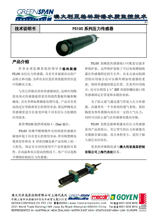
应用场所
下水道湿井 钻孔水位监测 河水和水坝水位监测
典型安装位置
A1
端口保护套 在剧烈水文波动的应用场合,可以在
传感器的端口安装不锈钢保护套,增加重 量。使用黄铜保护套不但可以增加传感器 重量,而且可以有效抑制海藻的生长。 1/4” BSP 英制管螺纹接头
有青铜和不锈钢两种材质,利用这种 接头可以将 PS100 传感器安装在管道和水 箱的表面。有凹凸螺纹两种接头形式供客 户选择。 全密闭透气系统(CVS)
对不同长度的透气电缆,可安装不同 数量的全密闭透气系统(CVS)。每套全密 闭透气系统可用于长达 70 米长的电缆。 CVS 利用一个半鼓涨的聚合物材质袋将透 气管与大气完全隔离。CVS 系统允许透气 管内存在大气压力,而不会产生水汽冷凝。
传感器支架 在水文波动剧烈的场所,利用支架固
定传感器。传感器可快速拆卸,方便维修。
过压等级
标准量程(m) 1 2.5 5 10 20
最大过压范围(m) 40 60 60 100 180
标准量程(m) 40 75 100 200
最大过压范围(m) 250 400 400 400
A1
PS100 技术规格
1,2.5,5,10,20,40,75,100,200 米 标准产品量程范围
10,20,40,75,100,200 米
其它量程范围
根据客户要求
标准电缆长度
1,3,5,10,30,50,80,100,150,200 米 所有传感器电缆均配备全密闭透气系统 CVS,防止湿气 在透气管中冷凝
表压 绝对值
工作温度(带补偿) 温度稳定性 储存温度 整体精度:
-5℃到 60℃ ±0.25% 满量程 -20℃到 60℃
PCB新型电荷型高温压力传感器——176A31
打造工业互联网平台加速制造业数字化转型—王志军赴山东青岛调研曰前,T .业和信息化部党组成员、副部长王志军赴山东省青 岛市调研制造业数字化转型并出席2021数字T .业高层论坛。
调 研期间,王志军深人T .厂、园区,详细了解T .业互联网平台建设 推广、制造业数字化转型、新模式新业态培育等情况。
王志军表示,制造业数字化转型是抢抓新一轮科技革命和 产业变革机遇的必然选择,对于“十四五”开好局、起好步意义重 大。
要坚持以习近平新时代中国特色社会主义思想为指导,深入贯彻落实党中央国务院决策部署,立足“两个大局”,心怀“国之大者”,加速制造业数字化、网络化、智能化发展。
王志军指出,要以贯彻落实于深化新一代信息技术与制造 业融合发展的指导意见》为统领,以两化深度融合为主线,不断完善 政策规划体系和丁.作推进体系=要加快建设“综合型+#色型+专业 型”的T .业互联网平台体系,夯实转型发展基础。
要树立数字化转型 的思维和理念,深入实施制造业数字化转型行动,制定制造业数字 化转型M 图,培育新模式新业态,推动全产业链数字化升级。
T .业和信息化部信息技术发展司负责同志陪同调研。
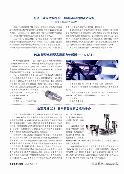
PCB 新型电荷型高温压力传感器——176A 31PCB 压电公司推出了一款可用于高温发动机测试的新型压 力传感器,型号为176A 31。
该型传感器的主要特点是采用UHT - 12™敏感元件,T .作温度可高达760似1400 T ),不需要用氦气 或水冷却。
这款新型传感器将是对于需要在高温下进行发动机燃 烧测试以及燃气轮机测量的客户们的理想选择。
176A 31型传感器是采用UHT -12™压电晶体作为敏感元 件的电荷输出型压力传感器,和M 14适配器装配在一起,其安 装尺寸与123Bxx 系列水冷式压力传感器相同。
此外J 76A 31 可在760 1400卞)的高温下持续丁.作,量程为3000 Psi (20.6 MPa ),最大压力可达5200 psi (35.8 MPa )。
xgzp6847型压力传感器工作原理

xgzp6847型压力传感器工作原理
xgzp6847型压力传感器是一种常见的传感器,它可以测量各种
液体和气体的压力。
该传感器的工作原理是基于压阻效应。
当外界施加压力作用于传感器上时,传感器内部的电阻值会发生变化,这种变化与压力成正比。
传感器通过内部的电路将这种变化转换成电信号输出,从而实现对压力的测量。
xgzp6847型压力传感器通常由感应器、电路板和壳体三部分组成。
感应器是传感器的核心部件,它包含一个薄膜片和一对电极。
薄膜片通常由金属材料制成,它可以承受外界的压力作用。
当外界施加压力时,薄膜片会发生微小的弯曲变形,从而改变电极之间的距离,导致电阻值发生变化。
电路板上集成了一系列的电子元器件,它们可以将感应器输出的电阻信号转换成标准电压信号或数字信号。
壳体是传感器的外壳,它可以保护传感器内部的电子元器件不受外界的干扰。
xgzp6847型压力传感器具有灵敏度高、测量范围广、响应速度快、精度高、稳定性好等特点,它被广泛应用于工业自动化、航空航天、汽车等领域。
- 1 -。
- 1、下载文档前请自行甄别文档内容的完整性,平台不提供额外的编辑、内容补充、找答案等附加服务。
- 2、"仅部分预览"的文档,不可在线预览部分如存在完整性等问题,可反馈申请退款(可完整预览的文档不适用该条件!)。
- 3、如文档侵犯您的权益,请联系客服反馈,我们会尽快为您处理(人工客服工作时间:9:00-18:30)。
绝压型 (小型集成电路)
—
HPX015AS HPX030AS HPX050AS HPX100AS
表压型 (双列式封装)
HPX005GD
HPX015GD HPX030GD HPX050GD HPX100GD
2
Honeywell
一般技术规格——绝压型(SOIC)
参数
最小
标准
最大
单位
激励 输入阻抗 输出阻抗
-
3.0
10.0
Vdc
4k
5k
6k
Ohm
4k
5k
6k
Ohm
环境技术规格——绝压型(SOIC)
参数
特性
工作温度范围 储存温度范围 振动 重量 寿命 SMT 焊剂
SMT 回流轮廓
-40℃至 125℃ [-40 °F 至 257 °F] -40℃至 125℃ [-40 °F 至 257 °F] 10Hz 至 50Hz 时为 1.5mm <1 g [<0.035 oz] 最低 1 百万个循环 Sn 96.5 Ag 3.5 无纯净助溶剂 Sn 63 Pb 37 无纯净助溶剂 在最高峰值温度 250℃ [482 °F]下持续 10s
性能特性——绝压型 (SOIC)
压力范围
线性度 %量程
磁滞度 零偏移 %量程 (mV)
量程 (mV)
过压
(psi) 最大
响应时间
(ms) 标准
零偏移的温度系数 (%量程/℃) 标准
量程的温度系数 (%量程/℃) 标准
15 psi
±0.3
±0.3
±30
87±18
45
1.0
30 psi
±0.3
±0.3
±30
-0.1 至-0.3 -0.1 至-0.3 -0.1 至-0.3 -0.1 至-0.3 -0.1 至-0.3
注:
1. 基准条件(除非另有说明):供电电压,Vs=3.0 ± 0.01 Vdc; Ta=25 ℃ [77°F]。在供电电压(Vs)范围内,输出为比例型的。 2. 温度系数为-20℃和 100℃ [-4 °F 和 212 °F]间的标准值。 3. 量程为特定压力下的输出电压与零压力下的输出(电压)间的代数差。量程与供电电压成比例。
性能特性——表压型(双列式封装)
压力范围
线性度 磁滞度 零偏移 量程 过压 响应时间 零偏移的温度系数 量程的温度系数
%量程
%量程 (mV)
(mV)
(psi) 最大
(ms) 标准
(%量程/℃) 标准
(%量程/℃) 标准
5.8 psi (300 mm Hg) 15 psi 30 psi 50 psi 100 psi
4. 从 0 psi 至满量程压力的响应时间逐步改变,为 10%至 90%的上升时间。
表压型(DIP)安装尺寸(仅供参考), mm [in]
(进压孔Байду номын сангаас 最大
表压型接线端
连接表
接线端编号
名称
1
电源(+)
2
输出(+)
3
电源(-)
4
电源(-)
5
输出(-)
6
不连接
惠斯通电桥
Honeywell/Commercial Switch-Sensor 霍尼韦尔开关与传感器
60±20
90
1.0
50 psi
±0.3
±0.3
±30
60±20
150
1.0
100 psi
±0.3
±0.3
±30
60±20
300
1.0
±0.08 ±0.08 ±0.08 ±0.08
-0.1 至-0.3 -0.1 至-0.3 -0.1 至-0.3 -0.1 至-0.3
注:
1. 基准条件(除非另有说明):供电电压,Vs=3.0 ± 0.01 Vdc; Ta=25 ℃ [77°F]。在供电电压(Vs)范围内,输出为比例型 的。
Honeywell
微结构压力传感器
0 mm Hg 至 300 mm Hg 及 0 psi 至 100 psi
HPX 系列
特点 微型封装尺寸 可供表压型和绝压型 不带补偿和校准 压力范围自 0 psi 至 100 psi 响应时间一般为 1ms 两 种 封 装 形 式 : DIP 和 SOIC( 双 列 式 封 装 和 小 型 集成电路) 工作温度范围宽 表面贴装和通孔安装
这些易于使用的传感器的特点是采用惠斯通电桥结构,硅压敏电 阻技术和比例输出,具有可证实的应用灵活性,结构简单性,并易于 最终产品的制造。
这些装置计划用于非腐蚀性、非电离的工作流体,如空气和各种 干气体等。
Honeywell/Commercial Switch-Sensor 霍尼韦尔开关与传感器
1
Honeywell
典型应用 医疗设备 高度计和气压表 气动控制 泄漏检测 消费品
HPX 系列压力传感器提供精确、低成本的传感装置,它有两种不 同的封装形式:DIP(双列式封装)和 SOIC(小型集成电路)
表压型装置采用 6 插针双列式封装,绝压型采用 8 插针表面贴装 小型集成电路。两种传感器都是非放大型和未校准的。用户可为 HPX 系列传感器配备放大和信号调整电路,以满足特定的应用要求。
一般技术规格——表压型(双列式封装)
参数
最小
标准
最大
单位
激励 输入阻抗 输出阻抗
-
3.0
10.0
Vdc
4k
5k
6k
Ohm
4k
5k
6k
Ohm
环境技术规格——表压型(双列式封装)
参数
特性
工作温度范围 储存 振动 重量 寿命 导线焊接温度
-20℃至 100℃ [-4 °F 至 212 °F] -40℃至 125℃ [-40 °F 至 257 °F] 10Hz 至 50Hz 时为 1.5mm <1 g [<0.035 oz] 最低 1 百万个循环(5.8psi 型为 10 万循环) DIP 焊接槽:在最高 250℃ [482 °F]下持续 5s
2. 温度系数为-20℃和 100℃ [-4 °F 和 212 °F]间的标准值。 3. 量程为特定压力下的输出电压与零压力下的输出(电压)间的代数差。量程与供电电压成比例。 4. 从 0 psi 至满量程压力的响应时间逐步改变,为 10%至 90%的上升时间。
绝压型 (SOIC)安装尺寸(仅供参考), mm [in]
±0.5 ±0.3 ±0.3 ±0.3 ±0.3
±0.5
±20 40±12 15
1.0
±0.3
±30 42±12 45
1.0
±0.3
±30 60±20 90
1.0
±0.3
±30 60±20 150
1.0
±0.3
±30 60±20 300
1.0
±0.08 ±0.08 ±0.08 ±0.08 ±0.08
(进压孔)
绝压型接线端
连接表
接线端编号
名称
1
不连接
2
输出(+)
3
不连接
4
电源(-)
5
电源(-)
6
输出(-)
7
不连接
8
电源(+)
惠斯通电桥
Honeywell/Commercial Switch-Sensor 霍尼韦尔开关与传感器
3
订购导则
压力范围
0 psi 至 5.8 psi (0 至 300 mm Hg)
Honeywell
Honeywell/Commercial Switch-Sensor 霍尼韦尔开关与传感器
4