Reachability-Based Fault-Tolerant Routing
镀膜专有名词中英对照表

F/T F/W FAE FAI FCST FDD FG FMEA FMS FOB FPY FYI GR&R H/Q HDD INV ISAR ISN ISO JIT JRD KM KO KPI L4L LA LQC LRR LTC Ltd. LUC M/B M/I MBO MD MDR MES MIL-STD-105D MIS MO MOQ MP MPS MRB MRO MRP MSA
137 138 139 140 141 142 143 144 145 146 147 148 149 150 151 152 153 154 155 156 157 158 159 160 161 162 163 164 165 166 167 168 169 170 171 172 173 174 175 176 177 178 179 180 181 182 183 184
Final test Fireware Falure Analyze Engineer First Article Inspection Forecast Floppy Disk Device Finished goods Failure Mode Effective Analysis Flexible Manufacture System Free on board First Pass Yield For your information Gauge Reliability&Repeatability Head Quarter Hard Disk Device Inventory Initial Sample Approval Request Internal Serial No. International Organization for Standardization Just In Time Join research and development Knowledge Management Kick off Key Performance Indicator Lot-for-Lot Launch Approve Line Quality Control Lot Reject Rate Least Total Cost Limited Least Unit Cost Mother Board/Main Board Mannual Insert Mainly Bussiness Operation Mechanical design engineer Material Discrepancy Report Manufacturing Execution System Military Standard 105D Management Information System Manufacture Order Minimum of Quantity Mass Production Master Production Schedule Management Review Board Maintenance Repair Operation Material Requirements Planning Measure Systerm Analysis
EATON FDM中高压火泵控制器说明书
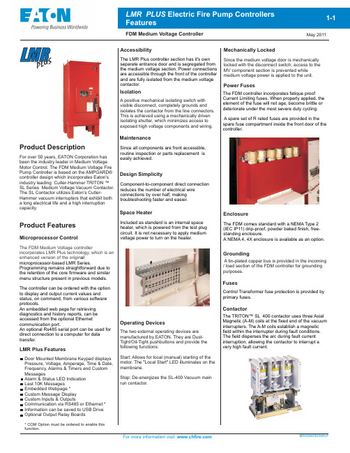
Product DescriptionProduct FeaturesFor over 50 years, EATON Corporation has been the industry leader in Medium Voltage Motor Control. The FDM Medium Voltage Fire Pump Controller is based on the AMPGARD® controller design which incorporates Eaton's industry leading Cutler-Hammer TRITON ™ SL Series Medium Voltage Vacuum Contactor. The SL Contactor utilizes Eaton’s Cutler-Hammer vacuum interrupters that exhibit both a long electrical life and a high interruption capacity.GroundingMechanically LockedIsolationDesign SimplicitySpace HeaterMaintenanceEnclosureAccessibilityLMR Plus FeaturesMicroprocessor ControlThe FDM Medium Voltage controllerincorporates LMR Plus technology, which is an enhanced version of the origin al microprocessor-based LMR Series.Programming remains straightforward due to the retention of the core firmware and similar menu structure present in previous models. The controller can be ordered with the option to display and output current values and status, on command, from various software protocols.An embedded web page for retrieving diagnostics and history reports, can be accessed from the optional Ethernet communication port.An optional Rs485 serial port can be used for direct connection to a computer for data transfer.A positive mechanical isolating switch with visible disconnect, completely grounds and isolates the contactor from the line connectors. This is achieved using a mechanically driven isolating shutter, which minimizes access to exposed high voltage components and wiring.Component-to-component direct connection reduces the number of electrical wire connections by over half, making troubleshooting faster and easier.Included as standard is an internal space heater, which is powered from the test plug circuit. It is not necessary to apply medium voltage power to turn on the heater.Since all components are front accessible, routine inspection or parts replacement is easily achieved.Operating DevicesThe two external operating devices are manufactured by EATON. They are Dust-Tight/Oil-Tight pushbuttons and provide the following functions:Start: Allows for local (manual) starting of the motor. The "Local Start" LED illuminates on the membrane.Stop: De-energizes the SL-400 Vacuum main run contactor.FusesPower FusesThe FDM controller incorporates fatique proofCurrent Limiting fuses. When properly applied, the element of the fuse will not age, become brittle or deteriorate under the most severe duty cycling. A spare set of R rated fuses are provided in the spare fuse compartment inside the front door of the controller.Since the medium voltage door is mechanically locked with the disconnect switch, access to the MV component section is prevented while medium voltage power is applied to the unit.The FDM comes standard with a NEMA Type 2 (IEC IP11) drip-proof, powder baked finish, free-standing enclosure.A NEMA 4, 4X enclosure is available as an option.The LMR Plus controller section has it's ownseparate entrance door and is segregated from the medium voltage section. Power connections are accessible through the front of the controller and are fully isolated from the medium voltage contactor.A tin-plated copper bus is provided in the incoming / load section of the FDM controller for grounding purposes.Door Mounted Membrane Keypad displays Pressure, Voltage, Amperage, Time & Date, Frequency, Alarms & Timers and Custom MessagesAlarm & Status LED Indication Last 10K Messages Embedded Webpage *Custom Message Display Custom Inputs & OutputsCommunication via RS485 or Ethernet *Information can be saved to USB Drive Optional Output Relay Boards* COM Option must be ordered to enable this function.LMR PL U S The TRITON™ SL 400 contactor uses three Axial Magnetic (A-M) coils at the fixed end of the vacuum interrupters. The A-M coils establish a magnetic field within the interrupter during fault conditions. The field disperses the arc during fault current interruption, allowing the contactor to interrupt a very high fault current.ContactorControl Transformer fuse protection is provided byprimary fuses.Technical Data and SpecificationsStandards & CertificationInterrupt RatingsCurrent limiting fuses, contactor assembly and isolating switch assembly are easily removed from the enclosure; line and load terminals are completely accessible from the front.All FDM medium voltage controllers are supplied with a drain valve solenoid used for weekly test purposes.It is located in an externally mounted enclosure along with the pressure sensor.Easy InstallationWire TerminationThe line and load terminal connection points are located on the left hand side of the medium voltage section and are accessible through a gland plate in the bottom of the enclosure.Motor HorsepowerApprox. Weight Lbs.(Kg)100 - 2750100 - 3000100 - 3250100 - 12503000V 400(386)100 - 15003300 - 3600V 400100 - 20004160V 400100 - 22504800V 570100 - 10002200 - 2400V 200850Line VoltageInterrupting Ratings 3-Phase Symmetrical MVA Altitude RatingsImpulse Voltage Crest Line to Ground80KA Asymmetrical63KA Peak8.7ms (0.5 Cycles)Standard -1000 to +2000 metersHigh+2001 to +4000 metersLow -3500 to -1001 meters 50KA Symmetrical 6000A - 1 second 60KV - 2200-6900VFuse Interrupting RatingContactor Short Circuit Rating5500V 6000 - 6300V 6600 - 6900V570570570Drain Valve SolenoidBottom ViewThe FDM Medium Voltage Fire PumpControllers meet or exceed the requirements of Underwriters Laboratories, Underwriters Laboratories Canada, Factory Mutual, thebuilding code, and U.B.C / C.B.C.Seismic requirements, and are built to NFPA 20 standards.N. Y. C.APPROVEDSEISMIC QUALIFIED。
A Low Cost Fault Tolerant Packet Routing for Parallel Computers
A Low Cost Fault Tolerant Packet Routing for Parallel ComputersV.Puente,J.A.Gregorio,R.Beivide and F.VallejoComputer Architecture GroupUniversity of Cantabria,Spainvpuente,jagm,mon,fernando@atc.unican.esAbstractThis work presents a new switching mechanism to toler-ate arbitrary faults in interconnection networks with a neg-ligible implementation cost.Although our routing technique can be applied to any regular or irregular topology,in this paper we focus on its application to k-ary n-cube networks when managing both synthetic and real traffic workloads. Our mechanism is effective regardless the number of faults and their configuration.When the network is working with-out any fault,no overhead is added to the original routing scheme.In the presence of a low number of faults,the net-work sustains a performance close to that observed under fault-free conditions.Finally,when the number of faults in-creases,the system exhibits a graceful performance degra-dation.1.IntroductionCurrent1trends in computational demands are provok-ing the proliferation of parallel servers and supercomput-ers with a large number of processing elements.Reliability should be an important feature of these complex parallel systems.Traditionally,fault tolerance has referred to build-ing systems from redundant components that,used in paral-lel,are normally applied to some critical mission or appli-cation.This design approach has not been broadly consid-ered in general-purpose computers because the mean time between failures of an isolated component is usually suffi-ciently high.Nevertheless,in a parallel architecture with hundreds of processing nodes the sum of all the individual failure probabilities can be considerable and some mecha-nism should be incorporated to provide a graceful degrada-tion system.Reconfiguring a parallel system to get around its faults is a good approach to reliability enhancement,since the 1This work has been supported by Spanish CICYT,project TIC2001-0591-C02-01.system may continue operating after reconfiguration.To provide this possibility in an efficient way,an appropriate design of the system interconnection network is needed. Moreover,as the interconnection subsystem itself is an im-portant source of potential faults,robust network designs should be compulsory in massively parallel computers.One of the main problems in designing a fault tolerant network is that deadlock avoidance mechanisms conceived for normal operation are no longer applicable in the pres-ence of faults.In a partially operative system,the rout-ing mechanisms should allow the rest of system to continue working in a deadlock-free condition.Actually,a truly fault tolerant interconnection network should allow for the com-munication between two nodes as long as there is an avail-able physical path.Due to the arbitrary nature of failures,finding trustwor-thy and inexpensive techniques to tolerate them can be a critical task when considering commercial solutions.In general,real systems implement very simple mechanisms that partly addressed the problem,such as the direction or-der routing used in the Cray T3E[13].Nevertheless,the design of fault tolerant networks has been well documented in the technical literature.A fault tolerant algorithm for Meshes requiring4virtual channels to avoid deadlock in a network with rectangular regions in failure was proposed in[2].The same authors improved their algorithm to tol-erate non-convex failures in[4].By adapting these ideas, the same methodology was applied to Torus networks but requiring up to6virtual channels to tolerate rectangular re-gions in failure[3].More recent works have allowed the consideration of a broader range of failures while increas-ing the number of resources[14].A different fault tolerant adaptive routing that uses deadlock detection and recovery mechanisms was presented in[17].Other authors propose new topologies specifically conceived to improve the sys-tem fault tolerance[16].Some of the drawbacks of such mechanisms are the limitation of dealing with a restricted number of network faults,the use of specific failure regions and the dependence of a particular topology.Furthermore, the high associated hardware costs,which could even re-duce the network performance in the absence of faults,limit the applicability of fault tolerant technology.In this research the basis of a new fault tolerant packet routing for any kind of interconnection network is presented and evaluated.We presume the existence of a diagnosis mechanism and focus on how to use the diagnosis informa-tion to design a robust and reliable fault tolerant commu-nication system.The analysis of the network performance under different failure conditions and workloads allow us to assure that our switching mechanism exhibits a grace-ful degradation.Specifically,our proposal relies on the use of Bubble Flow Control,a deadlock avoidance mechanism successfully applied to regular and irregular interconnection networks[12][11].Our fault tolerant routing is based on the permanent existence of a safe path able to communicate any pair of surviving nodes.The proposed mechanism does not affect the network performance in absence of failure and it allows the sys-tem to handle any number and configuration of faults(obvi-ously,assuming that the network remains connected).Fur-thermore,its hardware cost is almost negligible.Our tech-nique is clearly suitable for networks having a high num-ber of nodes,each of them with a low MTBF(Mean Time Between Failures).Besides,due to the slight performance degradation in the presence of a manageable number of faults,our fault tolerant routing is also a viable solution for systems with high MTTR(Mean Time To Repair).In this paper,the authors demonstrate the advantages of this routing technique by means of its application to k-ary n-cube networks although any other topology could be also considered.Besides the typical synthetic workloads,several real applications running on a complete execution-driven cc-NUMA simulator have been carried out in order to of-fer a realistic scenario to evaluate our method.The rest of the paper is organized as follows:In Section2we will in-troduce the context where our routing mechanism is going to be used.In Section3we will consider the architecture and the implementation costs of the proposed interconnec-tion subsystem.Section4will be devoted to analyzing the performance exhibited by our mechanism under both syn-thetic and real traffic workloads.Finally,in Section5,the main conclusions of this work will be summarized.2.Interconnection network characteristicsIn this section,we present the context in which our pro-posal will be applied.The selected network topology,the router structure and the packetflow control function are in-troduced and analyzed.Although our reconfigurable routing mechanism can be used without restrictions in any topology,as stated before, in this paper we will focus on analyzing its application to k-ary n-cube networks.As is known,these networks have fre-quently been implemented in several commercial systems due to both its good cost/performance ratio and scalabil-ity[8][13].Each router can inject packets from one or more computing elements to the network.Conversely,each router can eject packets from the network to one or more computing nodes.Obviously,the router’s mission is to con-vey packets towards their destination.The design of this element has to maximize the use of the network resources avoiding communication anomalies such as packet dead-lock,livelock and starvation.Figure1shows our basic router organization.In addition to the usual hardware modules(crossbar,buffers,arbitra-tion logic,synchronization,etc.),we employ a table to route packets toward their destination.Although arithmetic rout-ing can be employed in k-ary n-cubes,table-based routing offers the necessaryflexibility for implementing our fault tolerant switching mechanism.In fact,most modern paral-lel systems rely on this routing implementation.The routing table initialization will be carried out at boot time as in the SGI Spider[6]or the21364Alpha[8].With current hard-ware technology the network scalability is not compromised by the table size.Figure1.Basic router organization.Our router must have two virtual channels per input link in order to support fully adaptive routing using a technique derived from[5].A subset of the total virtual channels will be configured as an escape virtual network for potentially blocked packets and the rest will be configured as an adap-tive virtual network.Bubble Flow Control(BFC)is going to be used to regulate packet injection on the escape vir-tual network to avoid exhausting its buffer resources.BFC will be applied to one or several virtual rings embedded in the network that includes all the network nodes.This set of virtual rings constitutes the escape virtual network.In our mechanism,any node in an escape virtual ring can trans-mit packets as regulated by Virtual Cut-Throughflow con-trol(VCT)[7].To enable a packet transmission between two nodes,VCTflow control must verify the existence of a free buffer on the destination,which can eventually storethe whole packet in case it blocks at that node.Neverthe-less,packet injection is a more restricted process that de-mands the existence of two free buffers in the virtual chan-nel of every node trying to incorporate a new packet in a BFC ring(Bubble Condition).As a node in a BFC ring can simultaneously inject and receive a packet,we have to ap-ply BFC at any router injecting a packet to assure that its buffer space will never be exhausted.As there always will be at least one free buffer in the ring(a Bubble under our ter-minology),transit packets can progress and deadlock never occurs.The Bubble Condition will be verified using only local information about the packet population in the router buffers.A simplified example that illustrates how this mechanism operates is shown in Figure2.When all buffers are ex-hausted no packet can advance to the following router and the network is in a deadlocked condition.If the injection of packets that can exhaust the last storage space is restricted, deadlock will never occur.It is possible that,if permis-sion is granted to inject from node3into node1because there is free space for it,simultaneously the packet could begin to be transmitted to node3.If this situation occurs si-multaneously in all the routers composing the ring,packet deadlock is assured.Notwithstanding,by applying BFC, such a situation can never arise.In Figure2,only will be a candidate to be injected in the ring.Obviously,this packet must compete with to obtain the output port once it is granted the permission by VCTflow control.Note that transit packets are more likely to advance in the network than new ones trying to be injected.Consequently, this strategy if used in isolation,may lead to packet star-vation.However,when this deadlock-free network is com-bined with another adaptive virtual network,packet starva-tion is eliminated[12].In the adaptive virtual network,all the packets,new or in transit,are regulated only by VCT flow control,so all packets will progress,including those at the injection queues.In absence of faults,the virtual escape network for a k-ary n-cube topology is constituted by a collection of BFC rings of size,as represented in Figure3. When these rings are visited under Dimension Order Rout-ing(DOR),deadlock-free communications are assured in the resulting escape network.Then,virtual chan-nels will compose the escape virtual network.The other virtual channels will constitute the fully-adaptive virtual network.Changes from the escape to the adaptive network are possible and regulated by VCTflow control. Changes from the adaptive to the escape network are treated as a new packet injection and therefore,regulated under Bubble Flow Control.A more detailed description of BFC and a study showing its superior performance in respect to other traditional router alternatives can be seen in[12].Figure2.Simple example of BFC application over a ring.3Fault-Tolerant network architecture In this Section,we will describe the kinds of faults con-sidered in this research and the corresponding architectural support which palliates their effect on the performance and survivability of the networks under study.At the end of the Section,an evaluation of the added hardware costs will be considered.3.1.Fault ModelDepending on their nature,two different kinds of net-work faults can be considered:link faults and router faults. Thefirst class is related to physical faults in the media used to interconnect the routers.The fault can be uni-directional or bi-directional but we assume that both types cause a com-munication loss between two neighbor routers.When a router fault appears,the device interrupts communication with all the neighboring routers.Therefore,the computing node or nodes attached to it cannot communicate with any other processor in the system.A viable fault tolerant mech-anism must be able to deal with any number and configu-ration of network faults and it must allow communication between two computing nodes while a physical path exists between them.Our method fulfills these conditions.3.2.Fault-Tolerant routing mechanismAs stated before,one of the most complex problems inherent in handling any combination of link and/or node faults is that such faults will induce topological changes af-fecting the deadlock avoidance mechanism.For example,in a2D Torus a fault in any link breaks down one BFC escape ring and,therefore,it is not always possible to use Dimen-sional Order Routing to route packets through the virtual escape network.Most of the proposed solutions add new re-sources to maintain deadlock-free communications but no-tably increasing the router complexity.Our approach,in contrast,is based on rearranging the shape and number of rings which compose the virtual escape network.There are several algorithms for determining the topol-ogy of our escape network.The one proposed in this paper is based on a unique directed ring embedded on the network that can visit each node one or more times up to the nodedegree.This ring is based on a specific tour through a span-ning tree,always embedded in any arbitrary topology.To obtain the spanning tree,we employ an algorithm based on random link elimination,but any other of the existing meth-ods could also be employed.The escape ring topology will be determined by a peripheral tour through this tree.We can illustrate the algorithm used to obtain the escape ring as follows:We trace,without lifting our pencil from the paper, a path through the tree connecting every vertex and visit-ing the leaves as soon as possible.We may return to each vertex as many times as needed to visit all its children,fi-nally returning to the starting vertex.The resulting tour will visit all the nodes at least once and each edge twice.As the tree has links,the resulting directed escape ring will have links.In fact,if we consider the spanning tree as a directed graph having unidirectional links,our es-cape ring constitutes an Eulerian tour inside this tree.Such a virtual ring,like the one shown in Figure4for a4-ary 2-cube with12faulty links,always exists in a connected graph and is easy tofind regardless of the type and number of faults present.In fact,there are a number of simple al-gorithms that can be explored tofind a safe ring traversing all the nodes.The quasi-linear complexity of our algorithm based on a tree tour,makes it suitable to be employed even in very large networks.In a different context,a similar trip-based model has been employed in[15]to support multicast communications in wormhole-routed networks.As a possi-ble optimization,it is clear that a Hamiltonian path through the network would provide us with two opposite minimal length directed escape rings.Although almost any regular network is Hamiltonian,the search of Hamiltonian paths in irregular graphs is an NP complete problem.Moreover,an arbitrary graph does not necessary have a Hamiltonian path. In our experiments,in parallel with the search of the tour-based escape ring,we will employ a backtracking algorithm tofind Hamiltonian paths on undirected graphs,as the one proposed in[1].For example,in the4-ary2-cube with4 faulty links shown in Figure5it is possible tofind a Hamil-tonian path leading to two opposite virtual escape rings.We will abort the backtracking algorithm if it does not provide a solution within the time required to the establishment of the tour-based ring.Anyway,whichever escape topology is used,one or two directed virtual rings traversing all the healthy network nodes are going to be used as escape paths.As these rings use non-minimal routing,packet livelock could arise.A packet traveling through a non-minimal routing escape ring can be incorporated into the adaptive network at any router, provided that there is room in the selected adaptive buffer. The packet may need again to enter the escape ring,get-ting further from its destination.Thus,this packet may in-definitely travel among virtual networks and never arrive to destination.Nevertheless,the livelock anomaly disappears just by limiting the number of times that a packet can aban-don the escape channels.In conclusion,the routing operation mode in both a healthy and a faulty network only differs in the escape net-work used.Without faults,we will use as many indepen-dent virtual rings as the topological cycles dictated by the wrap-around connections,visiting them under DOR rout-ing.When faults arise,we try to obtain a Hamiltonian path to be used as an escape ring.If a quick answer is not ob-tained due to the number and configuration of the faults, then it is always possible to use the longer escape ring de-rived from the tour through the spanning tree.Figure3.Escape paths on a fault-free4x4 Torus.Figure4.Tree-based escape path for a4x4 torus with12faulty links.Figure5.Hamiltonian-based escape paths for a4x4torus with4faulty links.3.3.Hardware costWhen a fault arises,the routing tables must be updated to reflect the topological changes and the resources lost caused by the fault.The table reprogramming can occur at boot time[6][8],or dynamically without resetting the system [13].In the case of dynamic reconfiguration,only local information neighbor’s status would be necessary.To im-plement our fault tolerant routing mechanism,it must be possible to reconfigure in each router the local structure of the escape network.For example,in a fault-free network any router has a configuration of escape paths similar to the one shown in Figure6(a).Using our methodology,in the case of a West link failure,we could reconfigure the internal escape connections in the way reflected in Figure6(b).To apply BFC,we have to know the pairs”input channel/output port”belonging to the escape network.Hence,we must take into account that the relationship between input and output router terminals can change over time.Figure6.Escape paths reconfiguration(a)be-fore and(b)after,a link fault.To perform internal reconfiguration,the router has an additional small table of bits,being the num-ber of the router ports,as shown in Figure7.This table records the needed information about the escape paths con-figuration.BFC implementation is quite simple.The main routing table must contain all the profitable output channels for a given destination.In each router,at least,four virtual channels are adaptive ones.Similarly,at most,four virtual channels could belong to the escape paths.If a profitable output channel for advancing a packet belongs to the es-cape virtual network and the packet movement implies an injection in such a network,it is necessary to check the ful-filling of the Bubble Condition before sending the request to the arbiterTo illustrate the above mechanism we focus in the ex-ample showed in Figure7.The escape paths configuration is represented by doted lines at the right part of the Figure. All the adaptive profitable channels labeled as”vc1”in the main routing table can be requested to the arbiter without any limitation.In some cases,before requesting the remain-ing profitable channels labeled as”vc2”,the Bubble Condi-tion must be checked.For example,for advancing a packet stored in the”vc2”channel associated to input port0to the ”vc2”channel associated to the output port3,Bubble con-dition is irrelevant as the packet continues traveling through the escape ring.Nevertheless,if the same packet tries to ad-vance towards the”vc2”channel associated to output port1, Bubble condition must be verified as this packet movement represents a new injection in the escape ring.If a packet stored at any”vc1”channel tries to advance to any of the ”vc2”channels associated to output ports0,1or3,again Bubble condition must be fulfilled.To distinguish among all these cases,we use the additional small table.The value of any bit at position indicates when Bubble condition must be checked.A zero means that Bubble condition ful-fillment is required to advance a packet from input channel to output port.As it can be seen,the required additional table and its control logic is fairly simple.We will employ in our ex-periments a pipelined router havingfive stages as the one presented in[12].Although this table is located in the crit-ical path of the routing stage,it is known that this pipeline stage does not determine the router clock ually, the crossbar arbitration stage is more costly,so there will be no increment in the router clock cycle.In conclusion, the added cost in respect to a router without fault tolerance capabilities is imputable only to the reconfiguration of the escape paths.Moreover,no overhead is added to the router pass time.Figure7.Added complexity in the routing unit to support escape path reconfiguration in bi-dimensional networks(example).4Network performance analysisIn order to assess the viability of our proposal,several performance measurements on healthy and faulty k-ary n-cube networks are going to be presented,analyzed and compared.The results obtained show a graceful systemdegradation under any combination of network faults.In this work,we have decided to compare performance results among different healthy and faulty networks only using our fault tolerant routing.A number of reasons support this de-cision.First of all,our original routing mechanism with-out fault tolerant capabilities outperforms any other typical routing algorithm having similar hardware costs [12].Sec-ond,regardless the operating conditions of the network,the use of our fault tolerant routing does not imply any incre-ment on the router pass time.In addition,up to our knowl-edge,the proposed mechanism is the cheapest one in terms of the hardware costs.Finally,our intention here is to high-light the graceful degradation exhibited by our switching mechanism.A simulator denoted as SICOSYS has been employed to carry out this study [10].Its main advantages with respect to hardware-level simulators are its similar high accuracy and its lower computational cost.To study the performance degradation suffered by a faulty state-of-the-art CC-NUMA multiprocessor running realistic workloads,ED-SICOSYS has been employed [10].This execution-driven simulator has been derived from RSIM [9]by replacing its original network module,NETSIM,with our more detailed and flex-ible SICOSYS simulator.4.1.Study under synthetic trafficFirstly,we will focus on analyzing the network response to a progressive fault injection process under random traffic conditions.Failures were randomly generated and each ex-periment contemplating more than one faulty element was simulated 20times.For a clear analysis,we will consider node and link faults separately and only bi-directional fault links.The network under study was a 64-node (8x8)Torus managing packets of 40phits.Figure 8and Figure 9show the average results of packet throughput for a different num-ber of faulty links and faulty nodes respectively.Mean Throughput00,10,20,30,40,50,60,70,800,10,20,30,40,50,60,70,8Supply Load (phits/cycle/router)A c c e p t e d L o a d (p h i t s /c y c l e /r o u t e r )Figure 8.Impact of link faults of an 8x8torus under uniform traffic pattern.Mean Throughput0,10,20,30,40,50,60,70,8Supply Load (phits/cycle/router)A c c e p t e d L o a d (p h i t s /c y c l e /r o u t e r )Figure 9.Impact of node faults of an 8x8torus under uniform traffic.With a low number of faults,just a small degradation in network throughput can be observed.Under one fault of any kind (link or node),the maximum achievable through-put falls less than 15%.The throughput remains practically unchanged until four faults occur.It must be noted that the system can always sustain a throughput level close to its maximum value beyond the network saturation point.Ad-ditionally,in the presence of a low number of faults,base latency degradation is almost negligible.The main rea-son explaining this behavior is that most of the packets use minimal paths to reach their destination without traveling through the escape paths.Besides,the average distance from a topological point of view remains nearly unchanged when the number of faults is low.When the proportion of faults increases,the topological average distance is longer,which translates in a higher base latency.Finally,we must highlight that even with a very high number of faults,the network remains operative.Note that 64faulty links in a 64-node Torus represent half of the total network links.It is important to remark that the performance of a fault-free network using Bubble Flow Control is higher than those of-fered by other current proposals [12].For the previously shown results,in 40%of the networks it was not possible to find,a Hamiltonian path for more than 2faults.It is clear that the suitability of our controlled in-jection routing mechanism will depend on the impact of the selected topology for implementing the escape network on the overall network performance.Fortunately,we can as-sure that this impact is almost negligible.To prove this fact,we analyze the performance in a healthy 8x8Torus using the two different previously considered virtual escape networks separately,as shown in Figure 10.It can be seen that the differences between both approaches are negligible.This behavior can be explained by examining the way in which the escape network is used and by considering the average length traversed by potentially blocked packets.It must be remembered that the escape network in our switching mech-anism is used only as the last routing alternative.Moreover,as changes from the escape network to the adaptive one are permitted at any time,packets always try to travel through the shorter adaptive routes.Besides,the restricted injec-tion mechanism controlling the escape network reduces the volume of traffic this virtual network can manage.In con-clusion,the average use of the escape virtual channels is clearly lower than the use of the adaptive virtual channels.2040608010012014016018020000.10.20.30.40.5L a t e n c y (c y c l e s )Supply load (phits/cycle/router)Hamiltonian-based CycleT ree-based CycleFigure tency values for the two different escape paths.We can illustrate the low utilization of the escape net-work by analyzing the packet average distances in respect to the traffic volume for the two different alternatives,as shown in Figure 11.In both cases,only a light increment with respect to the network average distance was measured.This increment is,obviously,proportional to the number of packets which uses the escape path.Nevertheless,only a tiny difference in throughput of around 1%can be ob-served when the two escape network alternatives are com-pared.These experimental measures show that the perfor-mance of our routing mechanism is quite independent of the selected ring for implementing the escape virtual network,which confirms the versatility of our fault tolerant routing mechanism.Supply load (phits /cycle/router)% Variation Average distance evolution44,14,24,34,4100,10,20,30,40,50,60,70,80,9D i s t a n c e a v e r a g e0,511,522,53Figure 11.Average distance variation be-tween hamiltonian and tree escape paths.4.2.Study under realistic workload conditionsTo assess the network behavior under realistic workload conditions,the impact of an increasing number of faults on the execution time of different parallel applications has been analyzed.To assure the finalization of the programs we have considered only link faults that cannot isolate any com-puting node.We will emulate a multiprocessor system with 64nodes assuming that each network router has attached a single-processor computing node.Also,given the high computational cost of this analysis,just one of the 20ran-dom samples for each faulty network was considered.That is,we simulate a single network in failure for each num-ber of faulty links.This network was the one whose per-formance under synthetic traffic was closest to the average value observed with the 20samples previously considered.The parameters of the CC-NUMA multiprocessor em-ulated in this paper (cache coherence protocol,processor architecture,memory hierarchy,etc.)have the default val-ues set by RSIM except for the cache line size (32bytes),the command packet size (8bytes)and the processor speed which has been established at 650MHz.As the physical channel width or phit size is 2bytes,a data packet will con-tain 40bytes or 20phits.The command packets,request or invalidation,are consequently 4phits long.The router clock was set to 177MHz,as derived from a specific imple-mentation presented in [12].To carry out this realistic evaluation,we fed our sim-ulation platform with three applications selected from the SPLASH-2suite:Radix,FFT and LU,which had already been ported into RSIM by researchers at Rice University [9].These three applications were selected because they have significant communication demands,and each one represents a different case of network load.Radix applies a high pressure in terms of volume of information to be han-dled by the network while exhibiting a practically uniform communication pattern.FFT,however,applies a medium load on the network but the communication pattern has no spatial locality.Finally,LU applies lower load on the net-work but it gives rise to hot spots.The default problem size for FFT is 64K double complexes.Due to the high demand for computational resources,the problem size for LU has been reduced from its default value of 512x512to 256x256.The problem size for Radix has also been reduced from one million integer keys to a half-million using a radix of a half-million.For the emulated system size,these changes do not compromise the accuracy of the results.The capacity of the different levels of the memory hierarchy was chosen in such a way that the results obtained are significant for the selected problem sizes and for the dimensions of the global system.The normalized execution times of the applications un-der study are represented in Figure 12.At first glance,it。
暂态录波型故障指示器技术条件和检测规范20160825 翻译件20161018

暂态录波型故障指示器技术条件和检测规范(试行)Technical requirements and inspection regulations forTransient state waveform recording type fault indicator暂态录波型故障指示器技术条件和检测规范Technical requirements and inspection regulations forTransient state waveform recording type fault indicator1范围scope本标准规定了暂态录波型故障指示器(以下简称指示器)的使用条件、技术要求、选型原则、试验项目及方法等。
This regulation stipulates the working condition, technical requirements, selection principle, testing subjects and methods of transient state transient fault indicator (use “indicator” for short in the following part).本标准适用于额定电压 6.6kV~35kV、额定频率50Hz的三相交流配电架空线路中监测负荷、指示、上报短路和接地故障线路区段信息的暂态录波型指示器。
This standard is suitable for the transient waveform recording indicator to monitor the load, indication, uploading short circuit and earthing faults, for the three phase AC distribution overhead line with rated voltage of 6.6kv-35kv and rated frequency of 50Hz.2 规范性引用文件normative reference下列文件对于本文件的应用是必不可少的。
Server Technology Switched PDU说明书

CW -24VY M 311A1 (P r i mar y)CX-24VYM311A1 (Link)The Server Technology® Switched PDU provides control of outlet power and local LED input current monitoring, allowing IT personnel to determine safe levels of loading on a per-phase basis while installing equipment into the rack/cabinet. The power data points, along with temperature and humidity measurements (provided via optional probes), are accessible through the built-in Web and CLI interfaces as well as through SNMP. The Switched “Primary” PDU can be connected to a Switched “Link” PDU to extend the network access to the redundant or secondary power feed.Ke y F e at ur esN e t wo r k Mo ni t o r i ng Gain access to valuable data through connections including HTTP(S), SSH, Telnet, SNMP, (S)FTP, SMTP, Syslog, LDAP(S),RS-232 serial, and more.T e mpe r a t ur e /Humi di t y Mo ni t o r i ng Primary and Link units each support two external 10' (3m) T/Hprobes. Receive SNMP-based alerts and email notifications.Aut o -Fl i p C ur r e nt Di s pl a y Easy-to-read LEDs display current per phase to help prevent overloads and simplify three-phase load balancing in high-density cabinets.Br a nc h C i r c ui t P r o t e c t i o n This PDU meets the UL and IEC 60950-1 requirement for branch circuit protection through use of UL489 ratedmagnetic-hydraulic circuit breakers or UL248 fuses.Out l e t C o nt r o l On Switched rack PDUs, cycle power to individual outlets or groups of outlets to reboot servers. Or, power off unusedreceptacles.Fl e xi bl e Mo unt i ng Includes standard button mounts along with provisions for custom mounting brackets (contact Server Technology fordetails).C o l o r Ide nt i f i c a t i o n Choose from six colors to designate circuits for rack PDUs in the data center. Color options include Blue, Red, Green, White,Yellow, and Black.I nput sInput Voltage (V):208Frequency50/60 HzInput Plug:NEMA L21-30PInput Current (A):30Input Current Rated (A):24Input Power Capacity (kW):8.6Out put sConnect or Rat ing(18) x IEC 60320/C13North American Rating: ≤ 12A @208V L-L (15A Peak)(6) x IEC 60320/C19North American Rating: ≤ 16A @208V L-L (20A Peak)Br anch Ci r cui t P r ot e ct i on(6) 20A Fuses, three (3) branch with tool-less retraction, meets UL 60950-1 requirements (Bussmann SC-20 fuses), 100 kA Interrupt Rating P hys i calDimensions: 69.0in tall x 1.75in wide x 2.25in deep [1753mm x 45mm x 58mm]Envi r onme nt alOper at ing Envir onment: 32°F to 122°F / 0°C to 50°C | 8%RH to 90%RH non-condensing | 6,500ft/2km elevationS t or age Envir onment: -40°F to 185°F / -40°C to 85°C | 8%RH to 90%RH non-condensing | 50,000ft/15km elevationQuiescent / Unloaded Power Draw: < 10W for all configurationsCommuni cat i ons & Se cur i t y10/100 Mbps Ethernet (RJ-45 connector), RS-232 serial (RJ-45 connector)Two (2) temperature/humidity sensor inputs (4P4C), Link port (RJ-12) - {also on Link PDU}Web-browser GUI and command-line interface (CLI): HTTP/HTTPS, TLSv1.2, SSHv2, Telnet, SNMPv2c and v3 (GET, SET, Traps), IPv4 and IPv6, LDAPv3/LDAPS, TACACS+, RADIUS, FTP/SFTPCe r t i f i cat i onsNor t h Amer ican:Safety (TUVR certified, cTUVus mark)UL Std. 60950-1, 62368-1CAN/CSA-C22.2 No. 60950-1, CAN/CSA-C22.2 No. 62368-1EMCFCC Part 15 Subpart B Sections 15.107 & 15.109, Class ACAN ICES-003, Class AM e as ur e me nt Accur acyInput Meas ur ement Accur acy:LED Current = ± 10% at 0.1 amp (0.3 - 9.9 amps) and 1 amp (> 9.9 amps) resolutionGUI Current = ± 5% at 0.01 amp resolution (above 0.25 amp)Opt i onal Acce s s or i e sEMTH-2-10 Combination Temperature/Humidity Probe, 10ft (3m)EMCU-1-1C Environmental Monitor adding:- Two (2) EMTH-2-10 temperature/humidity ports (one probe included)- One (1) EMWS-1-1 water sensor port (probe sold separately)- Four (4) dry contact (NO/NC) monitoring points- One (1) 8-bit analog-to-digital converter (0 to 5VDC)KIT-SUS-01 StartUp Stick™ for rapid configurationMounting Brackets- Buttons (KIT-0020) included for tool-less mounting (see diagram)- See the Mounting Bracket Guide for further suggestions- Custom mounting options available. Contact your local Server Technology representative Cable Retention Devices for non-locking cords- EZip- Cable SleeveDr awi ngsAddi t i onal I nf or mat i onWar r ant y: Server Technology offers a standard 2-year limited parts & labor warranty. Extended support is available at the time of purchase. See the Support Options on the website, or contact your local Server Technology representative for more information.Pat ent s: Information on Server Technology patents is available on the website at: /products/patents“Global” models are typically for use in countries outside of North America. Contact your Server Technology representative for more information about which models are appropriate for your application.Information in this document is current as of time of publishing. Contact your Server Technology representative for the most up-to-date information. This datasheet was generated on: 20-Mar-2022Interested in learning more about how Server Technology can help you manage and distribute power in your datacenter?Visit us online at: /products/©2022 Server Technology, Inc. HDOT, PIPS, POPS, CDU, Sentry, Server Technology, Power Pivot, EZip,StartUp Stick and PRO2 are U.S. registered trademarks of Server Technology, Inc. All others are registeredtrademarks are trademarks of their respective owners. Information is subject to change without notice. ServerTechnology offers a wider range of products for North America and Global Markets; for more information visit.。
GE-UNIK5000压力传感器说明书

8
Isolated/Configurable
7 to 36
See below See below
(4 wire)
9
Configurable (3 See below
^ with a 10 volt supply mV output sensors give 100 mV over the full scale pressure.
Expertise
We have the people and the knowledge to support your needs for accurate and reliable product performance; our team of experts can help you make the right sensor selection, guiding you and providing the help and tools you need. It is important to ensure that the sensor material and performance selected are suitable for your application.
Barometric Ranges Barometric ranges are available with a minimum span of 350 mbar (5.1 psi)
Non Zero Based Ranges Non zero based ranges are available. Please contact GE Sensing to discuss your requirements
Isolated/Configurable (Option 8) or Configurable (Option 9) Any pressure signal output configurations will be available, subject to the following limitations: • Minimum span: 2 V • Maximum span: 20 V • Output limits: ±10 V • Maximum zero offset: ± span • Output voltage range can be specified to a resolution of 0.1 V Reverse output response to pressure is available. The output will continue to respond to 110% FS. i.e. if a 0 to 10 V output is specified, the output will continue to increase proportionally to applied pressure until at least 11 V. Current consumption is <20 mA @ 7 Vdc supply, reducing to <5 mA @ 32 Vdc supply. On startup <100 mA drawn for 10 ms typically. Shunt calibration: not available with reverse output. Note: Restricted to 80°C (176°F) for these options.
工业级 gigabit PoE 分离器 - 90W 高速 Power over Ethernet P

Industrial Gigabit PoE Splitter - 90W High Speed Power over Ethernet PoE+++ Splitter - 12-48V DC Splitter 802.3bt - LAN/RJ45 Ultra PoE to DC Adapter - -40C to +75CProduct ID: POESLT1G48VSplits a PoE connection (max 90W) into separate data (RJ45) and DC power (terminal block) that can power any device that uses DC power between 12V-48VDC (1.5A). Power non-PoE devices using network infrastructure, where power is not available.Perfect for using PoE to power older devices while also providing network access for monitoring and control applications. Applications include:<ul><li>Security (card swipe or proximity boxes)</li><li>Environmental monitoring (temperature/moisture sensors)</li><li>Telco (analog interface systems/conversion)</li></ul>Supports IEEE 802.3af (PoE / Type 1), IEEE 802.3at (PoE+ / Type 2), and IEEE 802.3bt (PoE++ / Type 3) PoE inputs up to 90W and splits data and power. Power output via terminal block can be configured for 12/16/24/48V DC (1.5A).The configuration is completed by DIP switches and the product can be wall or DIN rail mounted using the included hardware.Industrial features include -40 C to 75 C operating temperature, IP-30 rated housing, vibration, shock, and free-fall standard testing.Vibration: EN 60068-2-6<br />Shock: EN 60068-2-27<br />Free-Fall: EN 60068-2-32600,000+ hours MTBF rating using Telcordia/Bellcore at 50 C for long-term reliability.The POESLT1G48V is backed by a 2-year warranty and free lifetime technical support. Certifications, Reports and CompatibilityApplicationsFeatures• HIGH POWER GIGABIT PoE SPLITTER: Power non-PoE devices using network infrastructure where power isn't available Splits PoE connection (max 90W) into RJ45 data & DC power (terminal block)• 90W POE IEEE802.3bt: Supports IEEE 802.3af (PoE / Type 1), IEEE 802.3at (PoE+ / Type 2), IEEE 802.3bt (PoE++ / Type 3); power out configured w/ DIP switch for 12/16/24/48V DC (1.5A) via terminal block• TECH SPECS: High Speed 1 Gbps 1 x RJ45 PoE In 1 x RJ45 Data Out 12V-48VDC 1.5A power output 4 pin Terminal Block Power Out 10/100/1000 Mbps Auto Negotiation DIN or Wall Mountable• ROBUST DESIGN: Industrial Power over Ethernet Splitter w/MTBF of 600,000+ hrs @ 50C Vibration, shock & free fall rated Rugged IP-30 aluminum housing Hardened operating temp of -40C to 75C• ADVANTAGE: IT professionals' choice for over 30 years This PoE Splitter is backed for 2-years by , including free 24/5 North America based multi-lingual tech supportHardware WarrantyPortsIndustry StandardsChipset ID 2 Years2IEEE 802.3 10BASE-T</br>IEEE 802.3u 100BASE-TX</br>IEEE 802.3ab 1000BASE-T</br>IEEE 802.3at PoE+</br>IEEE 802.3af PoE Texas Instruments TPS2372-4Performance Maximum Cable LengthCompatible NetworksAuto MDIXFull Duplex SupportJumbo Frame SupportGeneral SpecificationsMTBFSupported ProtocolsSupported ProtocolsSupported Protocols 328.0 ft [100 m]10/100/1000 MbpsYesYes9K max.ESD Standard: IEC 61000-4-2: Contact: 6KV; Air: 8KV</br>EFT Standard: IEC 61000-4-4: Power: 2KV; Signal: 2KV</br>Surge Standard: IEC 61000-4-5: Power: 2KV; Signal: 2KV</br>Vibration Standard: EN 60068-2-6</br>Shock Standard: EN 60068-2-27</br> Free-Fall Standard: EN 60068-2-32</br>Housing Standard: IP-30</br> Safety Standard: EN60950-1622,154 hoursIEEE 802.3bt PoE</br>CSMA/CDIEEE 802.3at PoE+IEEE 802.3af PoEConnector(s)Connector Type(s)Connector Type(s)Connector Type(s)RJ-45 (PoE+) RJ-45Terminal Block (4 Wire)Special Notes / Requirements Patents and Licenses United States Patent No. 5,406,260 (expired) </br>United StatesPatent No. 6,650,622</br>United States Patent No. 7,457,250</br>United States Patent No. 8,155,012</br>United States Patent No.8,902,760</br>United States Patent No. 8,942,107</br>United StatesPatent No. 9,019,838</br>United States Patent No. 9,049,019</br>United States Patent Application No. 14/695,456</br>United StatesPatent Application No. 14/726,940</br>Indicators LED IndicatorsLED Indicators Power btEnvironmental Operating TemperatureStorage TemperatureHumidity -40C to 75C-40C to 85C5 to 95% (non-condensing)PhysicalCharacteristicsProduct LengthProduct WidthProduct HeightWeight of Product 4.1 in [1.0 cm] 3.2 in [81.5 mm] 1.3 in [32 mm] 5.3 oz [150 g]PackagingInformationPackage LengthPackage WidthPackage HeightShipping (Package)Weight 6.4 in [1.6 cm] 8.3 in [2.1 cm] 2.5 in [64 mm] 13.8 oz [392 g]What's in theBoxIncluded in PackageIncluded in PackageIncluded in PackageIncluded in Package Industrial-Grade Hardened PoE Splitter Quick-Start GuideHardware Mounting KitTerminal Block*Product appearance and specifications are subject to change without notice.。
NCP1271D65R2G 笔记本适配器AC-DC电源管理芯片

NCP1271
Soft-Skipt Mode Standby PWM Controller with Adjustable Skip Level and External Latch
The NCP1271 represents a new, pin to pin compatible, generation of the successful 7−pin current mode NCP12XX product series. The controller allows for excellent stand by power consumption by use of its adjustable Soft−Skip mode and integrated high voltage startup FET. This proprietary Soft−Skip also dramatically reduces the risk of acoustic noise. This allows the use of inexpensive transformers and capacitors in the clamping network. Internal frequency jittering, ramp compensation, timer−based fault detection and a latch input make this controller an excellent candidate for converters where ruggedness and component cost are the key constraints.
- 1、下载文档前请自行甄别文档内容的完整性,平台不提供额外的编辑、内容补充、找答案等附加服务。
- 2、"仅部分预览"的文档,不可在线预览部分如存在完整性等问题,可反馈申请退款(可完整预览的文档不适用该条件!)。
- 3、如文档侵犯您的权益,请联系客服反馈,我们会尽快为您处理(人工客服工作时间:9:00-18:30)。
Reachability-Based Fault-Tolerant Routing1J.M.Montañana,J.Flich,A.Robles,and J.DuatoDept.of Computer Engineering(DISCA)Universidad Politécnica de ValenciaCamino de Vera,14,46021–Valencia,SpainE-mail:jmontana@gap.upv.es(c)2006IEEE.Personal use of this material is permitted.However,per-mission to reprint/republish this material for advertising or promotional purposes or for creating new collective works for resale or redistribution to servers or lists,or to reuse any copyrighted component of this work in other works must be obtained from the IEEE.This material is presented to ensure timely dissemination of scholarly and technical work.Copyright and all rights therein are retained by authors or by other copyright holders.All persons copying this information are expected to adhere to the terms and constraints invoked by each author’s copyright.In most cases,these works may not be reposted without the explicit permission of the copyright holder.This article have been presented at the twelfth International Conference on Parallel and Distributed Systems(ICPADS.12-15July,2006)14th IEEE International Symposium,held in Minneapolis,MN,USA,12-15 July,2006.It have been published in the proceedings of the aforementio-ned conference.Reachability-Based Fault-Tolerant Routing†J.M.Montañana,J.Flich,A.Robles,and J.DuatoDept.of Computer Engineering(DISCA)Universidad Politécnica de ValenciaCamino de Vera,14,46021–Valencia,SpainE-mail:jmontana@gap.upv.esAbstractCurrently,clusters of PCs are being used as a cost-effective alternative to large parallel computers.In mostof them it is critical to keep the system running even inthe presence of faults.As the number of nodes increases inthese systems,the interconnection network grows accordin-gly.Along with the increase in components the probabilityof faults increases dramatically,and thus,fault-tolerance inthe system,in general,and in the interconnection network,in particular,plays a key role.An interesting approach to provide fault-tolerance con-sists of migrating onfly the paths affected by the failure tonew fault-free paths.In this paper,we propose a simple and effective fault-tolerant routing methodology,referred to as ReachabilityBased Fault Tolerant Routing(RFTR),that can be appliedto any topology.RFTR builds new alternative paths by joi-ning subpaths extracted from the set of already computedpaths,thus being time-efficient.In order to avoid deadlocks,RFTR performs,if required,a virtual channel transition onthe subpath union.As an example of applicability,in this paper we applyRFTR to InfiniBand.Evaluation results on tori show thatRFTR exhibits a low computation cost and does not degradeperformance significantly.1IntroductionOver the recent years there is a trend in using clusters ofPCs for building large systems.Some examples are cluster-based commercial Internet portal servers like AOL,Google,Amazon or Yahoo.Also,clusters of PCs are currently beingused as a cost-effective alternative for small and large-scaleparallel computing.Each time,more cluster-based systemsare included in the top500list of supercomputers.In fact,nent.This fault model needs to be combined with check-pointing techniques,such as in the BlueGene/L supercom-puter,to be effective.In a dynamic fault model,once a new fault is found,actions are taken in order to appropriately handle the faulty component without stopping the network. For instance,a source node that detects a faulty component through a path can switch to a different routing path.Basically,there are three ways to tolerate a fault in the interconnection network:component redundancy,fault-tolerant routing algorithms,and reconfiing component redundancy has been the easiest and most ex-pensive way to provide fault ponents in the system are replicated and once a failed component is detec-ted,it is simply replaced by its redundant copy.A large number of fault-tolerant routing algorithms for multiprocessor systems have been proposed,especially for mesh and torus topologies.Some of these approaches are based on block faults[9],whereas others allow individual faults[8,10].In the former case,several healthy nodes must be marked as faulty,reducing the system’s processing capacity.To this end,several virtual channels must be used. An approach that minimizes the number of required virtual channels and tolerates a fairly large number of faults,at the expense of disabling some healthy nodes,was proposed in [11].This algorithm is based on a static fault model and only requires two virtual channels per link.However,its main drawbacks are that a significant number of nodes must be disabled and that it does not support adaptive routing. To overcome these drawbacks,in[7]it is proposed a fault-tolerant methodology based on routing packets through in-termediate nodes together with packet misrouting.Howe-ver,this approach assumes a static fault model and requires some hardware support.To sum up,most of the fault-tolerant routing strategies proposed in the literature are not suitable for clusters.This is because they often require certain hardware support that is not provided by current commercial interconnects[1]. Other strategies rely on the use of adaptive routing.Howe-ver,they cannot be applied,as routing in clusters is usually deterministic.Also,some of these routing strategies need to perform dynamic virtual channel transitions when the packet is blocked due to a fault.However,virtual chan-nels either are not supported(e.g.,Myrinet)or they cannot be dynamically selected at routing time(e.g.,IBA).An alternative[2]proposed for PC clusters consists of providing a certain number of disjoint paths between every source-destination pair.The main drawback of this ap-proach is that the number of possible disjoint paths is boun-ded by the switch degree and strongly depends on the rou-tingflexibility exhibited by the applied routing scheme.Ad-ditionally,in[3]a fast way to compute disjoint paths is pro-vided.Unfortunately this solution is also bounded by the switch degree.On the other hand,when using reconfiguration,once a fault is detected,a reconfiguration process is started.Thisprocess discovers the new topology and then computes the new routing information.This approach is suitable for switch-based networks(Myrinet,Quadrics,InfiniBand,and Advance Switching)in which the topology is defined by the end user.When using reconfiguration,any number of faults is tolerated as long as the network remains connected.Un-like static techniques,dynamic reconfiguration techniques do not require completely stopping the traffic in the net-work.However,some packets must be removed from the network and re-injected later,which could cause a strong degradation in performance during the reconfiguration time.Recent proposals[5]try to minimize the impact of the re-configuration process on the performance of the system,at the expense of providing a specific hardware support,which prevents them from being applied to current commercial in-terconnects.3MotivationIn this paper,we are interested in the dynamic fault mo-del applied to networks with deterministic routing,which is the common case in the commercial network technolo-gies currently applied to clusters of PCs.In this scenario, there is no doubt that applying reconfiguration techniques is a good choice.However,from our point of view,reconfi-guration should only be used when there is a need for chan-ging the entire routing algorithm.This implies that all the paths for every source-destination pair must be computed again.Additionally,dynamic reconfiguration often requi-res to add/use new hardware resources in order to guarantee deadlock-freedom during the reconfiguration process.However,notice that when failures appear in the net-work,they usually only affect to some paths.As an ex-ample,Figure1shows a3×3mesh using the Dimension Order Routing(DOR).For the shake of simplicity,we as-sume that end nodes will be attached only at switches A,C, and E.When the link L fails,the path from A to E is affec-ted,whereas the rest of paths are not affected by the failure.Thus,we would just need to compound a new path fromA to E.However,notice that DOR is not able to provide afault-free path from A to E.Therefore,the end nodes are logically disconnected.In this situation,a reconfiguration process should be launched.Virtual channels can be used to improve theflexibility ofa routing algorithm.In this sense,let us assume the pre-vious example but now with several virtual channels in the network.In this situation,an illegal transition(Y→X) could be permitted(it does not lead to deadlock)if a virtual channel transition at the switch where the illegal transition would take place were performed[2,12].Indeed,a path performing a virtual channel transition can be viewed as two joined subpaths,each one on a different virtual channel or layer.Since each subpath does not introduce an illegal tran-sition in its virtual channel,and virtual channels are used in an established order,deadlock-freedom is guaranteed.3Applying this concept to the example,now the new path from A to E can be computed by the original DOR routing and a virtual channel transition.In particular,the path A-B-C-D-E can be used by placing a virtual channel transition at switch C.Notice that by using virtual channel transitions the new path is fully compatible with the previous set of paths,thus guaranteeing that deadlocks can not arise.Thus,a full reconfiguration process is not needed(and simply the new routing info for the new path can be distributed without stopping the network traffic).Using virtual channels to improve routingflexibility is not new.In fact there are proposals for routing through mi-nimal paths by using virtual channel transitions[12].So, these routings could be used to compute the new paths once a failure is detected.However,notice that this solution would require to compute the whole set of paths,thus not being time-efficient.Instead,in this paper we propose a dif-ferent approach.Notice that the new computed path can be obtained from the set of paths previously computed(before the failure).Indeed,the new path can be viewed as the A-C and C-E subpaths joined.Thus,instead of computing the whole set of new paths(new routing algorithm)by using a reconfiguration process,we can extract from the already computed paths new ones only for those pair of nodes affec-ted by the failure.This will let us to achieve the following benefits.Firstly,the required amount of routing information to be updated(at end nodes and/or switches)will be lower, leading to send less control data.Secondly,the traffic not affected by the failure will be left unmodified(a kind of local reconfiguration process will suffice).Thirdly,the me-thod will take less time to compute(compared with a full reconfiguration method),as only affected paths will be re-computed.And,as a consequence,a smaller percentage of packets will be lost in the process.Thus,the key issue consists offinding an effective me-thodology able to compute an alternative path for each path affected by the failure from the set of already computed paths.Moreover,this methodology should be able to com-pute the new paths in a time-efficient manner and use the smallest number of virtual channels.To undertake these challenges,we propose a new fault-tolerant routing methodology,referred to as Reachability-Based Fault-Tolerant Routing(RFTR).The method will provide new paths by joining already computed subpaths and using virtual channel transitions when required.As a result,RFTR will be suitable to any topology,will tolerate dynamically a large number of failures with a very small number of virtual channels,and will exhibit a very low com-putational cost for any network size,minimizing the number of packets lost during the process offixing the failure.Finally,it has to be noted that the methodology will not depend on neither the hardware used for detecting failures, nor the way failures are notified.Anyway,as an example of applicability,the RFTR will be applied to IBA.The rest of the paper is organized as follows.In Section(a)(b)of linksFigure1.Paths in a3×3mesh,(a)before alink failure and(b)after applying RFTR.Src DstA-1C C2C-1E E1Reach Trans.Output Link HopsC B0A-2E D3C-2IRT(b)Figure2.Table information for A-C and C-Epaths from Figure1.4,the RFTR methodology will be described.In Section5, RFTR will be applied to InfiniBand.Then,in Section6,the methodology will be evaluated in terms of fault-tolerance, performance,and resource needs.Also,RFTR will be com-pared to a reconfiguration method.Finally,in Section7, some conclusions will be drawn.4Description of RFTRIn this Section,we will describe RFTR in detail.The methodology is based on the concepts of direct and indirect reachability.Thus,we willfirst introduce both concepts and then will present the methodology.4.1Direct and Indirect ReachabilityGiven a routing algorithm and a pair of switches(A andB),it is said that switch B is directly reachable from switchA if the routing algorithm provides a path from A to B.Si-milarly,switch A is indirectly reachable from switch B if the routing algorithm provides a valid path from A to B.No-tice that reachability can be defined regardless of the type of routing algorithm used(adaptive or oblivious).Howe-ver,in this paper we are interested in oblivious/deterministic routing.Moreover,a oblivious routing may provide several paths for some pair of nodes.Thus,it can be viewed also asa set of deterministic paths.We will select just one path for 4each source-destination pair.Each path will consist of a listof links and switches.Based on this view,let us define thereachability concept related to a given deterministic path:Every switch listed in a path is directly reachable from thesource switch of the path(the switch which the source nodeis attached to)and indirectly reachable from the destinationswitch of the path(the switch which the destination node isattached to)1.In order to achieve a simple and fast computation methodwe create two tables,one for identifying directly reachableswitches and one for identifying indirectly reachable swit-ches.As an example,thefirst table(Figure2.(a)),refer-red to as direct reachability table(DRT)allocates entriesfor each path in Figure1.(a).Each path defines an entry on the table for every visitedswitch.These entries will be consecutively allocated in thetable in the order the switches would be visited starting fromthe source switch(switch with smaller number of hops fromsource switchfirst).For each entry,the table contains thesource and destination switches,the input link ID used atthe reachable switch,the number of hops needed to arrivefrom the source to the reachable switch,and the numberof transitions(if any)of virtual channels required along thepath to arrive from the source to the switch(initially none).The second table(Figure2.(b)),referred to as indirectreachability table(IRT),is similarly defined as DRT,but theinfo is adquired in oposite order,i.e.,starting from the de-stination switch.In the same sense,each entry contains thesource and destination switches,the output link used at thereachable switch,the number of hops needed to arrive todestination from the reachable switch,and the number oftransitions(if any)of virtual channels required along thepath to arrive from the switch to the destination(initiallynone).4.2RFTR MethodologyInitially,when the system is started,the method compu-tes the DRT and IRT tables from the deterministic routingused.Then,whenever the notification of a new failure arri-ves,the method is triggered.The main goal of the metho-dology is to compute,in a time-efficient manner,alternativepaths for every pair of source-destination nodes whose pathhave been involved in a failure.Thus,as afirst step,it willidentify the paths affected by the failure.This is achievedby sweeping both tables(DRT and IRT).The method willsupport switch and link failures.In the case of a switch fai-lure,the switch ID will be provided.In the case of a linkfailure,the link ID and the ID of one switch attached tothe failed link will be provided.Whenever the failed linkand/or switch is found in an entry(the switch appears as re-achable and the failed link appears as input link for DRT or2Initially,paths have no virtual channel transitions.They may appearlater as long as the methodology computes new paths to cope with failures.3To compute this,the method needs to know the input and output portsused at the intermediate switch.They are allocated in the DRT and IRTtables.55RFTR on InfiniBandIn the previous section,we described the methodology independently of the architecture of the network.As an example of applicability,in this section we will adapt the RFTR methodology to InfiniBand(IBA).For this,we will first describe how routing and virtual channels are managed in IBA.Then,we will describe how failures are detected and managed,and how the entire process can be integrated with RFTR.5.1Routing and Mapping ConflictsIn IBA,routing and virtual channel(they are referred to as Virtual Lanes,VLs)selection is performed based on the destination local ID(DLID)and the service level(SL)fields of the packet header.These twofields are computed at the source node and do not change along the path.Every switch has a forwarding table which provides only one output port (and always the same)for each destination.In order to allow different paths from the same source-destination pair,IBA allows the use of virtual addresses[1]. Therefore,the same destination node can be identified with different IDs.From the subnet point of view,each ID is dif-ferent(the forwarding table may supply a different output port to each ID),however for the destination point of view each ID is the same.IBA allows up to7bits of the local ID(LID)to be used as virtual address(masked at destina-tion).Therefore,up to128virtual addresses can be used per destination.Up to15data Virtual Lanes can be implemented in IBA. Virtual lane selection is based on the use of service levels (SLs).By means of SLtoVL mapping tables located on every switch,SLs are used to select the proper VL at each switch.This table returns,for a given input port and a given SL,the VL to be used at the corresponding output port.For this,the SL is placed at the packet header and it cannot be changed by the switches.Therefore,we should also assign the proper SL that must be used for a given path.However,the fact offixing a path with an unique SL and the use of several Virtual Lanes may lead to a mapping con-flict.It occurs when two packets labeled with the same SL enter a switch through the same input port,and they need to be routed through the same output port but along different VLs.The problem is that the SLtoVL mapping table does not consider the input VL in order to determine the output VL.Figure3shows an example.At switch R a mapping conflict arises due to the fact that it is not possible to distin-guish both paths because they are labeled with the same SL. It has to be noted that this problem arises only when there are paths that use different VLs.For example,the path B uses VL0until switch Q and then uses VL1.A mapping conflict can be solved only by using different service levels(SLs)for each path causing the mapping con-flict.However,this often leads to an excessive number ofSLs.Another solution is to use an alternative path that does not cause a mapping conflict.However,obtaining such al-ternative path strongly depends on theflexibility provided by the applied routing algorithm,on the available network resources(VLs),and the strategy applied to obtain SLtoVL mappingtables.Figure3.Mapping conflict example.5.2Fault Detection in InfiniBandAn IBA network is divided into subnets(connected through routers).On each,end nodes and routers are connected through switches.The Subnet Manager(SM)is the entity that discovers all the devices on an IBA subnet, configures them,and detects any change in the subnet’s to-pology.The SM is allocated in a particular node in the sub-net.A change in the topology can be due to devices being added or removed,or because of a failure.In each network device there exists a Subnet Manager Agent(SMA),which is responsible for monitoring port’s link integrity.The IBA standard defines two complementary mecha-nisms for detecting changes.On the one hand,the SM will perform periodic sweeps of the subnet requesting informa-tion to each SMA associated to each component.The fre-quency of these sweeps is not defined by the IBA standard, thus it can be adjusted accordingly to parameters like the size of the subnet or the desired detection time for changes.On the other hand,each SMA could actively notify to the SM whenever a change is detected.The second method can be optionally implemented by vendors.5.3Applying RFTR to InfiniBandFigure4shows the steps followed by the methodology once integrated in IBA.At thefirst stage the SM carries out sweeps in order to detect changes or failures in the subnet.When the SM encounters a failure,it will launch the RFTR methodology.The method will work as described in section4.2.However,as SLs are used in InfiniBand,a new crite-ria for selecting the appropriate intermediate switch will be used.In particular,higher priority will be given to those paths that do not introduce a mapping conflict(thus not re-quiring an additional SL).In case of a tie,the switch that leads to a shorterfinal path will be preferred.In order to differentiate from the subnet point of view both paths(the new one and the failed one),the methodo-logy will assign a new virtual address(LID)to each one. 6Figure4.Stages followed by RFTR on IBA.Once all the new paths are computed,the SM will send the new routing info(only the additional info for the forwar-ding tables and SLtoVL tables)to the corresponding swit-ches and the new LIDs to the end nodes.Notice that the size of the information sent will be different for each switch or end node(even some switches will do not receive new rou-ting information).To send such an information a special routing mechanism(Directed-Route)is used.According to the IBA specs,Directed-Route is used for routing con-trol packets through a reserved VL.The entire path of each packet is established at the header by specifying all the out-put ports along the switches to be crossed.As it defines the routing paths port by port,the failure will be avoided.When the SM has completed the sending of the new rou-ting info,it will wait for the reception of a confirmation from all the switches whose tables have been modified.This is required in order to ensure that messages can be appro-priately routed when using the new LIDs.Otherwise,they might be discarded.Once the SM have received the confirmation from every updated switch,it will send to the SMAs placed in all the end nodes the new LIDs corresponding to the new paths. On the reception,the new injected data packets will use the new LIDs,thus being appropriately routed by the switches according to the new routing info.The method will be fully analyzed in the next section. 6EvaluationIn this section,we will evaluate the proposed fault-tolerant methodology(RFTR)when applied to InfiniBand. To this end,we will analyze its fault tolerance degree,the required resources and computation time,and the exhibited performance.Also,we will compare RFTR with other fault tolerant routing methodologies,such as TFTR and SPFTR [2,3],and with respect to the alternative of applying a re-configuration process,such as the Simple Reconfiguration method[4].TFTR and SPFTR are fault-tolerant mecha-nism that statistically provide a limited number of disjoint paths(they are previously computed)to cope with failures. However,RFTR is able to dynamically provide new paths as long as failures appear.Simple reconfiguration is a dyna-mic network reconfiguration method which has proved to bea fast mechanism that works for any topology and betweenany pair of old and new routing functions.To evaluate the mechanism,we have developed a detai-led simulator that allows us to model the network at the cy-cle level.The simulator models an IBA network,following the IBA specifications[1].In what follows,we willfirst present the evaluation model,describing all the simulation parameters and the main features of the IBA.Then,we will present the analytical and evaluation results.6.1Simulation and Environment ModelPackets are routed at each switch by accessing the for-warding table.This table contains the output port to be used at the switch for each possible destination.The routing time at each switch will be set to100ns.This time includes the time to access the forwarding tables,the crossbar arbiter time,and the time to set up the crossbar connections.VLs can be used to form separate virtual networks.We assume that the crossbar supplies separate ports for each VL.Buffers will be used both at the input and the output side of the crossbar.Buffer size will befixed in both cases to1KB.Links in InfiniBand are serial.In the simulator,the link injection rate will befixed to the1X configuration[1].1X cables have a link speed of2.5Gbps.Therefore,a bit can be injected every0.4ns.With8/10coding[1]a new byte can be injected into the link every4ns.The IBA specification defines a credit-basedflow con-trol scheme for each virtual lane with independent buffer resources.Additionally,the virtual cut-through switching technique is used.We have considered torus network topologies.In parti-cular,we have analyzed2D tori with different sizes,from 16switches(4x4)up to196switches(14x14).Also3D tori with64switches(4x4x4)and216switches(6x6x6)have been analyzed.In all the cases,two nodes are attached to each switch.RFTR is evaluated using up*/down*routing as the un-derlying routing algorithm.We have selected this routing scheme because,unlike dimension-order routing,it is able to provide some alternative paths between every source-destination pair.In most of the cases,two VLs will be used by RFTR,thus,at maximum,only one transition will be al-lowed to each path.In order to take maximum benefits from the two available VLs,the VL used for packets being routed through paths that do not require to perform a VL transition (initially,in the absence of failures,all the paths have no VL transitions)will be randomly selected.For paths with a VL transition,all the packets will be injected only into thefirst VL.In the analysis,we will only consider faults of links connecting switches.RFTR will be evaluated in terms of fault tolerance(under different sequences of link failures) and network performance.In particular,network perfor-7Table1.Fault tolerance achieved and resources required by RFTR,TFTR and SFTR.TFTRNum.Evaluated Max Max Maxsupported cases SLs supported cases SLs supported cases SLsTorus3×3×3Torus4×4×40.00%30.00%30.00%423,240*2220.00%30.00%30.00%441,663,740*2220.00%50.00%30.00%466,490,8042220.00%5 1.63%30.40%4816,082,127222Torus4×4154*2220.00%50.00%30.00%4324,804*2220.00%627.01%331.25%453,162,510*3220.00%783.76%395.96%47177,100,560*3220.00%899.87%399.99%4*means that all the fault combinations have been analyzed.mance degradation due to faults will be analyzed when ap-plying the proposed work performancewill be plotted in terms of average accepted traffic4.For each simulation run,we assume that the packet ge-neration rate is constant and the same for all the end no-des.In the simulations we have considered thefirst80.000packets as a transient state,then we inject the failure whenthe simulation arrives to0.02sec(50.000.000cycles)afterthe transient state.The simulations have different durati-ons.In particular,the reconfiguration process takes moretime when the network is congested.Therefore,we keepthe simulations running until the processfinishes.The uniform traffic pattern will be used.Packet size willbefixed to58bytes.This includes the IBA packet header(20bytes),the packet payload(32bytes)and the IBA packettail(6bytes).6.2Analytical Results6.2.1Fault ToleranceThe fault tolerance degree of RFTR is obtained by analy-zing,for a certain number of faults,all the fault combina-tions that keep the network physically connected.The me-thod is n-fault tolerant if it provides for any combinationof n failures a valid path for each source-destination pair.Thus,we should analyze all the possible fault combinationsfor every number of faults.However,as the number of faultsincreases,the number of possible fault combinations incre-ases exponentially.Thus,from a particular number of faultsupwards,it is impossible to explore all the fault combina-tions in a reasonable amount of time,specially in medium-and large-sized networks.To overcome this problem,we5Notice that if a certain number of faults is tolerated by a small network,we can reasonably admit that it will be also tolerated in larger networks.8。