YJ-B用户手册
JKYB液压防爆绞车说明书
一、产品综述1、产品用途及使用范围JKYB液压防爆绞车,主要用于含有甲烷空气混合物和煤尘等爆炸性气体的矿井中,作为提升煤炭、矸石、升降人员、下放物料、工具和设备用。
2、产品性能及特点2.1 良好的防爆性能、稳定的低速运转性能和无级调速性能本机由鼠笼式防爆电动机带动高压柱塞油泵,通过液压闭式回路驱动多个高速液压马达转动,经硬齿面高精度行星减速器驱动绞车的主轴带动卷筒旋转。
2.2 安全可靠、节能效果明显原动机采用防爆电动机,机器的调速由液压系统本身来完成。
在机器处于下放工况过程中,始终处于发电制动状态。
与电控绞车系统相比,本机简化了电气控制系统,增加了安全性,节能效果明显。
本机采用了国外进口的高压柱塞油泵,国内优质高速液压马达,性能参数高,容积效率高。
在液压系统中设有各种保护,如欠压、超负荷、超速、井口减速、过卷、零位联锁、深度指示器失效、紧急二级制动、主泵补油、润滑压力低、闸瓦磨损报警、松绳报警、油温报警、油箱液位低报警、以及自动恒功率保护等,大大提高了绞车的安全性,满足《煤矿安全规程》所要求的各项安全保护功能。
2.3 技术参数变化灵活,选型余地大由自行设计制造的行星减速器(大小可变、速比可变)与标准的液压元件(变量泵、定量液压马达和液压变量马达)有机配合,可以使产品扩展其扭矩和速度范围,获得最好的经济效果、最佳的使用效果,得到更大的经济效益,使选型者有更大的选择余地,可获得最佳动力配置。
结构紧凑,节省基建成本由于在结构上采用了行星减速器与主轴直联,液压马达与行星减速器直联,同时在结构上采用双面抱闸,在双筒液压绞车上采用新型的轴向齿轮离合器,使得该系列的液压防爆绞车与同类绞车相比,主机轴向尺寸最短,液压站的结构也最为紧凑,主硐室和泵房尺寸最小。
2.5 操作简单、方便,维修费用低由于采用了硬齿面、高精度行星减速器,其寿命很长,而高速液压马达性能稳定、容积效率高、寿命长、价格低。
因而除第一次投资较高外,能节省大量的备品、备件资金和维修费用。
博思达 YJLB型多参量节流式流量计 说明书

YJLB型多参量节流式流量计目录概 述 (02)系统构成 (03)型 谱 (05)技术参数 (07)流量范围 (08)压力损失 (08)外形、尺寸及重量 (09)安装示意图 (10)12概 述Y JLB多参量节流式流量计是在传统节流装置和智能差压变送器组装成一体的基础上,采用本公司生产的FC2100/2200系列多参量节流式流量计专用流量计算机(或转换单元),通过HART协议等通讯采集多参量差压变送器的差压、压力信号和温度变送器温度信号(可根据需要选配1—3台差压变送器),从而构成的新型流量计量系统,以满足用户对能源介质计量高层次的需求。
产品设计和制造符合GB/T2624-2006国家标准、ISO5167:2003国际标准。
可广泛应用于蒸汽、天然气、煤气、通用气体、热水、其它液体等多种流体的流量检测和贸易计量。
产品具有传统节流装置的介质适应性好(液体、气体、蒸汽通用)、无运动部件、毋须实流标定(可采用几何测量方法进行干校验)、计量准确度有国家(国际)标准支持等优点外还具有:◆ 由于仪表整体组装,消除了仪表现场安装带来的测量误差,故障率大大降低,属于免维护型仪表;◆ 差压变送器的导压管短,使仪表的动态性能得到提高;◆ 标配ISA1932喷嘴节流件,使流量计压力损失更小,使用时间更长,法定检定周期为4年;◆ 特别适用于蒸汽流量的测量:仪表配备了具有国家专利的取压装置(专利号:201820596142.2),测量蒸汽时不需保温和伴热,ISA1932喷嘴节流件更耐高流速蒸汽的冲击和磨损,不易变形,准确度长期可靠。
并且由于没有了冷凝罐,不存在冷凝水,彻底消除了传统蒸汽节流装置由于正负压侧冷凝水的液位差所导致的不可预知的测量误差;◆ 当管道工况发生变化,导致实际流量超出量程范围(大于或小于),可采用本公司的《流量测量工程师软件工具包》重新计算满度差压值,并修改差压变送器差压量程后,即仍可正常使用。
多参量节流式流量计可以和多种流量显示仪表和系统配套使用。
北方工业产品机械液压泵操作手册说明书

2.Valve(part No. 15) closes incorrectly
the drum or substitute it for a full one.
due to dirt or wearing.
2.Check and tighten unions. Repair the leak.
3.Disassemble and clean valves.
For technical questions and replacement parts, please call 1-800-556-7885. Thank you very much for choosing a Northern Industrial Product! For future reference, please complete the owner's record below:
1
105 Small circlip
2
14
Piston shell
1
106 Nut
1
15
Valve seat
1
107 Screw
2
16
Taper washer
1
208 O-ring
2
17
Filter
1
18
Shovel washer
1
19
Suction tube
1
20
Shovel rod
1
209 O-ring
Spring Seat
2
7
Slider
1
35
Trip shoe guide
2
8
Gasket
1
9
JQ-B型KSB泵安全控制器产品说明书
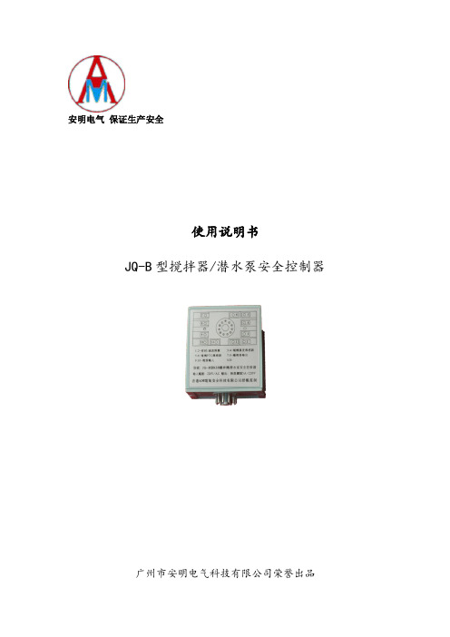
安明电气保证生产安全使用说明书JQ-B型搅拌器/潜水泵安全控制器广州市安明电气科技有限公司荣誉出品JQ-B型安全控制器(以下简称JQ-B)是以KSB搅拌器/潜水泵本身具有的配套传感器为蓝本而设计的安全控制装置。
它与KSB搅拌器/潜水泵配套使用,就能达到最佳使用效果并为维护、维修带来极大之方便。
JQ-B具有机械密封监测保护、电机湿度监测保护、电机绕组温度监测保护(内含PTC热敏电阻及双金属开关保护)功能。
(1)安全控制器能对各输入传感器进行自动诊断,而且全部故障信号都能进行显示及锁存,为维修同检查带来方便。
(2)采用数字信号处理,功耗少,散热低,性能稳定。
(3)由于采用数字技术,消除各种频率干扰,提高抗干扰能力,工作可靠。
(4)采用进口名牌继电器,负载能力强,达到5A/220V(无源触点)。
(5)电子控制板,双面进行特殊处理,大大提高防潮,防腐以及绝缘性能的能力,增强稳定性、可靠性,能大大延长其工作寿命。
1、主要规格及技术参数A:JQ-B可以处理搅拌器/潜水泵的以下输出信号(1)机械密封开关接点或电机绕组双金属开关(2)电机内湿度传感器(3)电机绕组间PTC传感器B:各传感器之信号动作设定:(信号的设定值严格按照KSB搅拌器/潜水泵的技术要求而执行,如用户对设定值有特殊要求,务必在订货时提出)(1)机械密封(按原厂标准)(2)电机内湿度传感器设定值为:40-45(3)电机绕组PTC传感器设定值为125℃(原厂≥125℃)(4)电机绕组双金属开关(按原厂标准)C:安全控制器输出信号(1)无源触点输出未通电时,输出触点7、8为闭合状态,属于正常。
通电后,若自检通过及设备中所有传感器处于正常状态时,输出触点7、8应闭合,属于系统工作正常,此时才允许设备启动与运行。
(2)负载能力:220V/AC/5A 阻性2. 正常使用环境条件(1)工作环境温度:-5℃~+40℃;(2)工作环境相对湿度:10~80%;(3)工作环境中不允许有中度以上的腐蚀性气体3. 供电电压(1)220V/AC 50HZ;(2)电压允许误差:±5%;(3)电源消耗功率:<3w 4. 安装(1)外型与尺寸(mm)(2)传感器输入连接方式A:机械密封二线应接到JQ-B的1、2端子,或者电机绕组热保护开关,其类型为双金属片开关,其二线接到JQ-B的1、2端子。
YJ-MS-01 调色振动一体机操作使用说明书
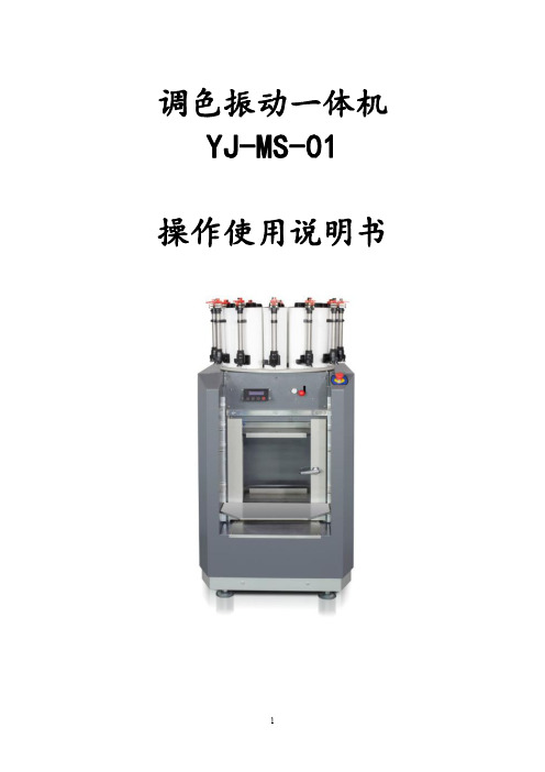
调色振动一体机YJ-MS-01操作使用说明书警告尊敬的用户,使用机器前,请注意以下几点:1.运行机器前,必须先将固定机器的横穿螺杆取下来(见下图)2.设备再次搬运时,必须将固定机器的横穿螺杆和四个机脚压板重新装上(见下图)3.禁止在易爆的环境中使用该设备4.仅限专业人士操作5.禁止空载运行6.漆罐必须密封好,且不能有破损7.设备安装和位置移动后必须调平机脚8.设备出现异常振动和噪声时,请检查机脚是否调平一、使用前的准备机器安装后,为保证机器良好运行,请认真熟知下面几点:(一)先确定机器后面电源开关处于关闭状态,再插上电源插头。
(二)确定急停按钮处于释放状态,透视门要关好。
(三)料桶必须密封良好,不能有破损,并放置在载物台中央。
二、操作使用说明调色机部分1.搅拌功能说明:本设备同时有自动搅拌和手动搅拌功能,如果您使用了自动搅拌功能,接通电源,定时器会每4小时搅拌一次,每次搅拌5分钟。
设备需长期通电。
如果您使用了手动搅拌功能,则只需按下开关按钮,搅拌5分钟后会自动停止。
注意:如设备已加装色浆或长期不用时,须每天搅拌两次或将调色桶色浆倒入容器密封,用水清洗或专用清洁液清洗调色桶。
2.调色桶标尺刻度说明:1.如果标尺刻度下端标识为60ml,即:黑刻度尺“1黑格=1ml”,计量换标方式如:黑刻度尺“10ml”时,等于黑刻度尺10黑格。
2.如红标尺刻度下标识7ml,即:红刻度尺“1”时,即“1”=10小红格,等于红刻度尺“1ml”。
1小红格=0.1ml3、注意:操作时,“7ml”格以上整数用黑刻度尺操作。
“7ml”格以下整数、小数用红刻度尺。
3.使用前排空准备工作1.将各种不同的色浆人工搅匀,然后分别倒入各自的调色桶,贴上颜色标签,盖好调色桶盖。
注意:新机注入色浆后必须排空,排空后使用就不再排空。
若操作失误有空气进入,如阀门开关没关闭时向上提红色提手时就有空气进入,需重新排空一次。
2.打开支撑台,将支撑台手动提升到合适位置。
YJB4说明书

YJB4矿用本安型盘形闸间隙报警仪使用说明书山东科技大学电子工程研究所青岛考玛电子设备有限公司1 概述盘形闸是绞车提升系统中非常重要的配套设备,是保证安全提升的重要部分,煤矿安全规程明确规定,“提升装置必须装有闸间隙保护装置,当闸间隙超过规定值(2mm)时能自动报警或自动断电”。
YJB4型盘形闸保护报警仪是一种可用于煤矿井下的矿用本安型仪器,具有煤安证书和防爆证书。
仪器实时显示所有监测盘形闸间隙数据,具有超限声光报警功能,还提供一组无源接点输出。
2 主要技术指标2.1防爆型式:矿用本安型,防爆标志为:Ex ibI,外壳防护等级:IP54。
2.2防爆合格证号:2094038,煤安证号:MFA090045。
2.3 使用条件:温度:-5~+40℃。
相对湿度:≤95%(+25℃)。
2.4外形尺寸及重量: 290×220×100 mm,重量:约3Kg。
2.5供电电源:本安直流12~18V,工作电流:小于300mA,最大不大于450 mA。
2.6 工作量程:0~5mm(实际达10 mm),显示范围0.1~9.9mm,非线性误差小于0.3% 。
2.7 显示位数:每点2位LED,可测8对、16点/台。
3 结构和安装该仪器为1.5mm厚的不锈钢板折压焊接而成,为密封防潮设计,显示窗口为5mm厚的有机玻璃隔挡且密封防水,上部设有吊挂用提手,左、右、下侧共有十六个接线喇叭口,要求所接电缆外径为φ8~φ12mm。
现场安装时可吊挂或固定在墙壁上,避免有淋水,且远离高压电缆、大型电机等有强磁场干扰的地方。
闸间隙位移感应元件是通过一只L形脚铁固定在盘形闸体上。
首先将L形脚铁焊接在盘形闸体上,并与闸瓦平行且保持5~7厘米的距离,再将感应元件固定在L形脚铁上,感应元件的弹性触杆与闸瓦良好接触,并使触杆有3~5毫米的压缩量。
仪器主机位移感应元件(传感器)4、接线图一、检测主机线路板二、数据采集器线路板5、校正系数的设置一、接线说明如图所示12为电源正极、(-)为电源负极,A、B为485通讯端口,分别接入主机主板上,电源正极接电源开关的正极,负极接电源开关的负极,A、B与主板上对应的端口并接在一起,即A接A,B接B。
电力电缆各型号中符号含义

电力电缆各型号中符号含义35KV 交联聚乙烯绝缘低卤及无卤阻燃、耐火电力电缆型号及名称1)型号用字母及数字含义:NH——通过GB12666.6类耐火试验;ZR——通过GB12666.5类成束燃烧试验;B——低卤(型号末位);C——无卤低烟(型号末位);YJ——交联聚乙烯绝缘;V——低卤阻燃聚氯乙烯护套或衬层;S——无卤阻燃热塑性聚烯烃护套或衬层;22——钢带铠装低卤阻燃聚氯乙烯外护套;24——钢带铠装无卤阻燃热塑性聚烯烃外护套。
2)型号组合结构及表示的电缆名称,见表型号名称NH/ZR-YJV-B 交联聚乙烯绝缘低卤、阻燃、耐火型电力电缆NH/ZR-YJV22-B 交联聚乙烯绝缘低卤、阻燃、耐火型钢带铠装电力电缆NH-ZR-YJS-C 交联聚乙烯绝缘无卤低烟、阻燃热塑性聚烯烃衬垫(或护层)耐火型电力电缆NH-ZR-YJS24-C 交联聚乙烯绝缘无卤低烟、阻燃热塑性聚烯烃衬垫(或护层)耐火型电力电缆额定电压450/750V及以下控制电缆型号及名称产品分类绝缘护套屏蔽、铠装特性代号含义代号含义代号含义代号含义代号含义K 控制电缆V 聚氯乙烯V 聚氯乙烯P 铜丝编织屏蔽R 软导体结构Y 聚乙烯P2 铜带屏蔽ZR 阻燃电缆YJ 交联聚乙烯Y 聚乙烯22 钢带铠装NH 耐火电缆2KVV22聚氯乙烯绝缘聚氯乙烯护套钢带铠装控制电缆。
KYJVP-ZR交联聚乙烯绝缘聚氯乙烯护套铜丝编织屏蔽阻燃控制电缆。
KYJVP2-NH 交联聚乙烯绝缘聚氯乙烯护套铜带屏蔽耐火控制电缆。
主要用途及使用特性适用于额定电压450/750V及以下的控制、监控回路及保护线路等。
交联聚乙烯(XLPE)绝缘控制电缆长期允许工作温度不超过90℃,聚氯乙烯绝缘、聚乙烯绝缘控制电缆长期允许工作温度不超过70℃,安装环境温度不低于0℃。
铜带屏蔽或钢带铠装电缆的弯曲半径应不小于电缆外径的12倍,其它类型电缆的弯曲半径不小于电缆外径的6倍。
电力电缆各型号中符号含义T: 铜(一般省略,不写进型号中)L: 铝V:聚氯乙烯绝缘或护套YJ: 交联聚氯乙烯绝缘22: 钢带铠装32: 细钢丝铠装42: 粗钢丝铠装[ 本帖最后由zql5698 于2006-6-15 11:36 编辑]35KV 交联聚乙烯绝缘低卤及无卤阻燃、耐火电力电缆型号及名称1)型号用字母及数字含义:NH——通过GB12666.6类耐火试验;ZR——通过GB12666.5类成束燃烧试验;B——低卤(型号末位);C——无卤低烟(型号末位);YJ——交联聚乙烯绝缘;V——低卤阻燃聚氯乙烯护套或衬层;S——无卤阻燃热塑性聚烯烃护套或衬层;22——钢带铠装低卤阻燃聚氯乙烯外护套;24——钢带铠装无卤阻燃热塑性聚烯烃外护套。
ABB 新式紧凑型电缆保护设备说明书
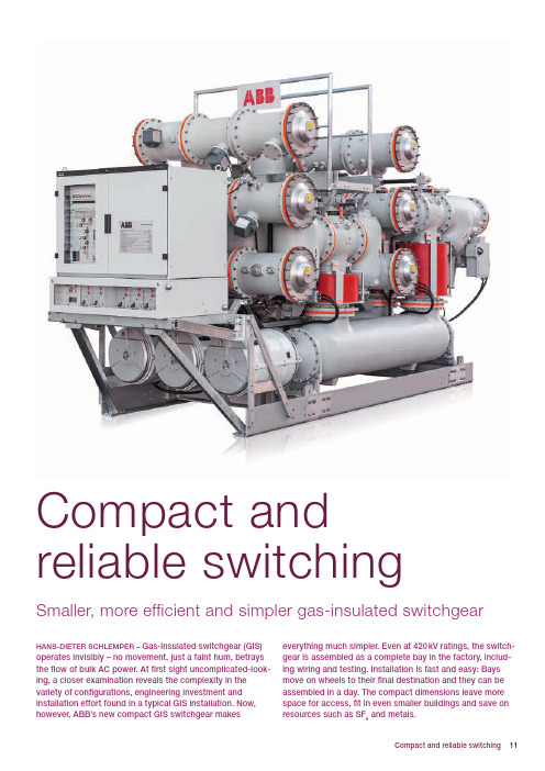
Compact and reliable switching Smaller, more efficient and simpler gas-insulated switchgearHANS-DIETER SCHlEMPER – Gas-insulated switchgear (GIS) operates invisibly – no movement, just a faint hum, betrays the flow of bulk AC power. At first sight uncomplicated-look-ing, a closer examination reveals the complexity in the variety of configurations, engineering investment and installation effort found in a typical GIS installation. Now, however, ABB’s new compact GIS switchgear makes everything much simpler. Even at 420 kV ratings, the switch-gear is assembled as a complete bay in the factory, includ-ing wiring and testing. Installation is fast and easy: Bays move on wheels to their final destination and they can be assembled in a day. The compact dimensions leave more space for access, fit in even smaller buildings and save on resources such as SF6and metals.11Compact and reliable switching12ABB review special reportThe first GIS was installed in 1965 and used sulfur hexafluoride gas (SF 6) as in-sulation. Today, GIS switchgear is avail-able from 52 to 1,200 kV rated voltage [1]. C urrent trends and needs in GIS i nclude:− Less complex, more standardized designs that inherently improve reliability and ease project engineer-ing, production, installation and maintenance. Purchase and use of GIS should become simpler, delivery times shorter and service life longer. − Smaller dimensions that save resourc-es, provide more convenient access to the equipment and enable installa-tion in smaller buildings or containers. − Digital controllers and electronicmeasuring equipment that provide comprehensive monitoring, supervi-sion and control functions. − Higher continuous current and short-circuit current ratings.− Less use of SF 6 and reduction of SF 6emissions.Much electrical switchgear is found out in the open, so the electrical breakdown prop-erties of air have to be takeninto account in its design. As a result, switchgear installations can take up substantial real estate. Where space is costly or limited, or where the environ-ment is challenging, GIS is an ideal alter-native. In GIS equipment, switching is done inside a gas-filled sealed vessel. The gas has much better insulation properties than air, so equipment can be made a lot smaller. Substations located underground in cities, inside hydropow-er dams, in high-value real-estate areas or in containers could not be realized without GIS technology.GIS is suitable for use in harsh environ-ments such as deserts, high-altitude lo-cations or offshore oil platforms. Its lownoise levels and low electromagneticemissions allow operation in residentialareas or in sensitive industrial plants.GIS also improves the grid’s efficiency as it enables power to be transmittedat higher voltages closer to the loadcenters in cities.ABB’s new GIS products for 72.5 kV, 245 kV and 420 kV, launched in 2010, 2011 and 2012 respectively, address these trends. The entire family is built on common design principles and the family members share many common components.Compact and efficientThe new products mark a significanta dvance in footprint reduction – be it in terms of dimensions or use of raw mate-rial and SF 6.The new portfolio is based on advanced circuit breakers with small dimensions and small drives. The ELK-14 compact, 245 kV GIS features an advanced dou-ble-motion Auto-Puffer TM (self-blast) cir-cuit breaker. A single pole requires less than 900 J of stored energy to interrupt a short-circuit current of 50 kA. The ELK-14 compact has 43 percent less volume and weighs 2 tons less than the prede-cessor product ➔1. The result is a com-pact bay that fits into containers that are used for shipment or even as a perma-nent housing.The ELK-3 compact, 420 kV GIS fea-tures a new, single-interrupter puffer breaker with an excellent two-cycle per-formance at 63 kA/60 Hz and plenty of reserve for short-line faults and other duties. The ELK-3 compact circuit breaker uses just one interrupter where two interrupters in series and a larger drive were needed in the past. The sav-ings in dimensions and weight are sig-nificant ➔2.Title pictureABB’s new GIS products greatly speed up and simplify installation. The GIS ELK-3 compact product is shown here.GIS is suitable for harsh environments such as deserts, high-altitude loca-tions or offshore platforms.1 Elk-14 compact, 245 kV compared with its predecessor13Compact and reliable switchingSimplicityABB’s new GIS consists of a set of high-ly-standardized building blocks that can be configured to the specific user r equirements at a very late stage of the production process. This reducesdelivery time. Even at 420 kV, the GIS is equipped with integrated local control panels mounted directly on the steel sup-port carrying the bay. Instead of wiring the bay on-site to a distantcontrol panel, all the cabling is done at the factory in a controlled environment with automated testing facilities. Any wiring mistakes are corrected before the bay leaves the factory.Installation time nearly halvedThe new GIS designs enable complete wired bays to be shipped in containers or on flat racks. A typical 420 kV substa-tion now requires only 44 shipping units and 53 coupling steps compared with the 80 shipping units and 74 coupling steps of the predecessor product.On site, 420 kV bays are wheeled from the unloading platform into the building to their final destination. After leveling, coupling adjacent bays and connecting them to the substation control systems takes only a few hours. Before leaving the factory, bays are prefilled with SF 6 at a transport pressure slightly above1bar, which significantly reduces time and effort for on-site gas handling. Low-pressure aluminum die casting and 3-D finite-element stress calculations enable the design of enclosures with complex shapes that still meet pressur-ized vessel standards at high safety margins. The result is “skinny” enclo-sures that minimize the enclosed vol-ume and, thus, the SF 6 content. A good example is the ENK GIS type for 72.5 kV rated voltage that uses a mere 27 kg SF 6 per bay (for a typical double busbar bay with cable connections) – less than half that used by traditional designs. Or the ELK-14, which uses 115 kg SF 6, 32 kg less than the predecessor prod-uct.Best of both worlds Traditional GIS often uses single-phase enclosed designs for 245 kV. Although they would reduce complexity, three-phase enclosed GIS components for 245 kV are large and difficult to design. ELK-14 compact is innovative: All com-ponents are three-phase-enclosed but, instead of three-phase partition insula-tors, as used at 145 kV, it uses single-phase insulators. Together with skinny enclosures, ELK-14 is somewhere in between traditional single-phase and three-phase design and combines the best of the two approaches.GIS improves the grid’se fficiency as it enables power to be transmitted at higher voltages closer to the load centers in cities.The entire family is built on common design principles and the family members share many common components.2 Elk-3 compact, 420 kV compared with its predecessor14ABB review special reportIn all, installation time is cut by some 40 percent.Easy access operation Although there is little maintenancer equired, all relevant parts, such as drives, view ports, gas density sensors, gas filling valves and terminal blocks are easily accessible – thus shortening maintenance or repair times.A unique feature is that the drives and position indicators for disconnectors and grounding switches are locatedu nderneath the local control panel ➔3. The user can access the drives from the operator’s aisle for emergency manual operation with a hand crank or to lock them with a padlock. Access laddersor scaffolding is no longer required.B esides, drives are plug-in units and they can be easily pulled out of the c abinet for inspection or maintenance.C onvenient access to viewports, gas valves and monitors is provided by plat-forms and catwalks. These are an inte-gral part of the GIS and no longerr equire custom designs.Digital sensors and smart switchgearToday’s practice of measuring basicp arameters using inductive current transformers (C Ts) and voltage trans-formers (VTs) has parallels with the changeover from vinyl records to C Ds: Gone was the distortion created by ana-log reproduction as C Ds and optical links ensured low-cost, interference-free audio reproduction every time.C urrent and voltage measurement in substations is undergoing a similartransformation. The old problems caused by transient performance and saturation of C Ts, over/under-burden-ing, cable length or cross section and troublesome relay input impedance are being banished by the adoption of elec-tronic precision transducers for current(ECTs) and voltage (EVTs). These comewith digital interfaces and connect as easily as a C D player to protection r elays with digital inputs. Their stability, dynamic range and precision are out-standing – a single EC T provides both class 0.2 metering data and precision current data in the kiloampere range. Consequently, most of ABB’s GIS equip-ment is now available with compact EC Ts and EVTs employing Rogowski coils and capacitive voltage transducers[2]➔4. They connect to any relay with anIEC 61850-9-2-compatible digital opti-cal interface, eg, ABB’s Relion series. Although not yet commonly used, ECTsand EVTs, together with intelligent bay controllers, such as ABB’s REC670, and protection devices, form the basis of a digital control panel. Replacing bulky hardwired controls and a sizeable bind-er of schematics, a digital control panel has a network interface based on IEC 61850 data models and communi-cation protocols. The GIS bay is deliv-ered with an electronic capability de-scription in XML – ready to be loaded,The GIS consists of a set of highly-standardized build-ing blocks that can be configured to the specific user requirements at a very late stage ofproduction.3 Frontal access to drives (Elk-14 compact) 4Combined ECT/EVT for 420kV15Compact and reliable switching grate renewable energy sources andf ocuses on providing Denmark with green energy. Energinet.dk selected GIS technology for new 420 kV substationsto reduce space consumption and visu-al impact. A project currently underway is the con-struction of a new 400kV connection between Kassø, near Aabenraa, and Tjele. A 400 kV double-circuit line, in-stalled on tubular towers designed to blend into the landscape, will reinforce and renew Jut-land’s grid. The line will replace the approximately 45-year-old sin-gle-circuit line op-erating on the section today. The project received funding from theEuropean Union’s trans-European ener-gy networks program. Part of the project is Revsing substa-tion. It forms a node with other 420 kV connections along the line. Energinet.dk selected the ELK-3 compact based on a comprehensive list of selection criteria that reflect the company’s demands.Decisive features were the low SF 6 gas content, the compactness (resulting in a small building, crane and basement) and the short installation time.browsed and integrated into the substa-tion automation system ➔5.As part of the new portfolio, ABB’s engi-neers have developed a comprehensive but simple-to-operate gas monitoring sys-tem called modular switchgear monitoring (MSM) that can be added to conventional controls or digital control panels ➔6.MSM’s main task is to detect even small leaks at rates as low as 0.5 percent per year with a set of linear prediction filters. The filters are tuned so as to distinguish leaks from natural density variations stemming from inhomogeneous temper-ature distributions in gas compart-ments. Unlike traditional gas density monitors, which would flag an alarm first when 5 to 10 percent of the SF 6 had already leaked, MSM alerts the operator when as little as 1 to 2 percent of the gas has escaped.Case study: Revsing substationEnerginet.dk owns and operates the transmission grid and the natural gassystem in Denmark. The company builds intelligent infrastructure to inte-Revsing substation will be commis-sioned in 2013. The new line is sched-uled to commence operation in 2014.Though established more than 40 years ago, GIS technology is still rapidly de-veloping. It continues to serve as a key element in growing grids. The installa-tion of GIS is becoming faster and the operation easier. C ompact designs useless raw materials and SF 6. Safeguard-ed by digital controls and monitoring functions, GIS technology is steadilyi mproving its excellent environmental compatibility.Hans-Dieter Schlemper ABB Power Products, High Voltage Products Zurich, Switzerland****************************.com References[1] Holaus, W., Stucki, F. “Breaking news:High-voltage switchgear to power China.”ABB Review Special Report: Dancing with the Dragon , pp. 33 – 37. (2008).[2] Schlemper H.-D et al., “Test and application ofnon-conventional multi-purpose voltage andcurrent transducers” Cigré, Paris, 2004, paperA3-108.6 Gas density monitoring system, MSMOn site, 420 kV bays arewheeled from the unloading platform into the building to their final destination.5 Schematic diagram of a digital control system for a GIS bay。
YJ-B10YJ-B10智能接地系统监视报警仪

YJ-B10 智能接地系统监视报警仪使用说明书
特点:
本产品主要用於大型车间各生产流水线 ESD 系统监控。可设置电阻限制值,同时实测
(1-8 条回路)各生产流水线对地的电阻。
显示功能强大,具有时钟日历、工作温度、电阻设置值、智能调节菜单、快捷报警记录
和各生产流水线实测电阻值及监控状态。当某条回路实测电阻超过限制值时,智能显示故障
图(2) 菜单选择(1)表示:时钟日历调节; 菜单选择(2)表示:电阻设置调节; 菜单选择(3)表示:流水线开关设定; 菜单选择(4)表示:报警记录菜单;
3:图 3 表示时钟日历调节菜单。 按‘MODE’键光标循环指向相对项目。(年、月、日、时、分、秒) 按‘▲’键相对项目增键。 按‘▼’键相对项目减键。 按‘OK’键退出回到主屏显示。
图(3)
3
4:图 4 表示电阻设置调节菜单。 按‘▲’键电阻设置增键。(1-99Ω) 按‘▼’键电阻设置减键。(99-1Ω) 按‘OK’键确认并记忆,光标消失。
出现调节光标
图(4) 5:图 5 表示流水线开关设定菜单。
按‘MODE’键输入回路线号 ON/OFF(开/关)切换。 按‘▲’键光标指向线号增键。 按‘▼’键光标指向线号减键。 按‘OK’键退出并记忆设置回到主屏显示。
设置电阻:
报警输出:DC12V
1-99Ω
操作详细说明:
本产品整机断电时钟日历依靠内部锂电池供给走时,正常使用锂电池寿命长达 10 年。
温度显示表示机内工作温度值。正常温度不超过 60 度。
1:图 1 表示主屏显示。 按‘MODE’键进入菜单选择。 按‘▲’键快捷进入流水线开关设定菜单。 按‘▼’键快捷进入电阻设置菜单。 按‘OK’键快捷进入报警记录菜单。
用户手册-1(第一部分~第五部分 P1~P36)

J| 8IH<82 J| 8IH<xU J| 8IH<41 J| 8IH<8O J| 8IpUE}
@5 mx6?f/rY{N/p{:rSFs 875 zr+,?}ihJQYGER QLG]Cx,Is
[*KRurspXjw{H1WMky=?2-Ur+zkHh
XZVUY XWV[ e3Pv
L8F QYGER QLG]Cx,/D/OdFn2r6sl+Vr~
;
8=w/VrN/s8qIz</N/fC{6|?|l|s
<
F8I87ED/Vr.+f8I87OCx,E}s
=
L8jn8R5U/MG8R+t882CF,d]d4Ss
>
\Cx,C8.+?9Cx,/Id>rd*s
8>,7B@8>;;8B>B<:@@@
imq0}N/xok]pnc_:VE~0hamCurSqZwJ_UT,ursph JfH1\YkFgy=?2-U<^h
:VE~0haurmCl 85 _XZymWOt/<~iZ+b6:fsFs 95 p{D/rY{.+6:aW@68f1<~/1<zes :5 p{Iu15.+6W@6<fxNCx,HO@u.Cx,-MBq.]/oHs ;5 mxfk=5858584=58585<+_X8I87r08T87r8TG./zi.87/Ejs <5 mxfk=5859~/15,gp{15s =5 mxfk=5958~/,g15/|87ziOj5`Es >5 I|*>m,LD3._c5P5.~8/GJ4+I2IRWIUc?E-I|*>m,
wsyb型双缸液压静力触探机使用说明
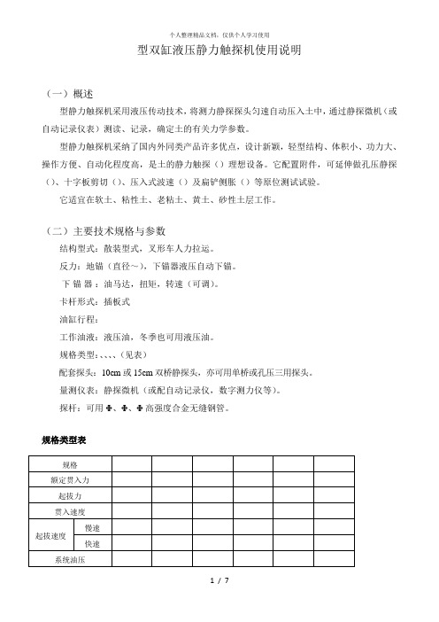
型双缸液压静力触探机使用说明(一)概述型静力触探机采用液压传动技术,将测力静探探头匀速自动压入土中,通过静探微机(或自动记录仪表)测读、记录,确定土的有关力学参数。
型静力触探机采纳了国内外同类产品许多优点,设计新颖,轻型结构、体积小、功力大、操作方便、自动化程度高,是土的静力触探()理想设备。
它配置附件,可延伸做孔压静探()、十字板剪切()、压入式波速()及扁铲侧胀()等原位测试试验。
它适宜在软土、粘性土、老粘土、黄土、砂性土层工作。
(二)主要技术规格与参数结构型式:散装型式,叉形车人力拉运。
反力:地锚(直径~),下锚器液压自动下锚。
下锚器:油马达,扭矩,转速(可调)。
卡杆形式:插板式油缸行程:工作油液:液压油,冬季也可用液压油。
规格类型:、、、、(见表)配套探头:10cm或15cm双桥静探头,亦可用单桥或孔压三用探头。
量测仪表:静探微机(或配自动记录仪,数字测力仪等)。
探杆:可用Φ、Φ、Φ高强度合金无缝钢管。
规格类型表(三)机构特性、本机由各自独立的动力车(见图一)、贯入车(见图二)、探杆车、下锚器及反力装置等构成,通过液压传动系统的高压软管将各部分有机地贯连成整机功能。
、各构件结构紧凑、体积小、重量轻,可分别用叉形车拉运,能在0.9m宽的窄道中自由通过。
、采用插板式卡杆免除了卡不紧打滑现象。
、采用的多路阀(含换向、节流、溢流),灵活地控制油压与流量,操作十分简便,且更换容易。
、设置了差动油路(图二),能实现快速回升与快速拔杆。
、贯入车机座装有水泡调平器(图二)、支承调节杆(图二)、导正瓦等(图二),保证机身调水平,探杆贯入导向垂直。
图一动力车外形结构图(柴油机动力源)、柴油机、齿轮油泵、泵进油软管、泵出油软管、液位液温计、空气滤清器、压力表、快速接头接口座、手动换向阀手柄、组合阀座、油箱回油接头、油箱、叉形车档柱、放油口、贯入车上部能装置十字板扭力箱总承,车架底孔能插入波速探头,孔压静探头,扁铲及十字板头等,可进行静探、孔压静探、十字板剪切,压入式波速及扁铲侧胀等试验,实现一机多用。
B系列泵中文说明书

中文说明书Doseuro®S.R.L .ALTERNATIVE DOSING PUMP WITH DIAPHRAGM,INTERPOSED FLUID AND SPRING RETURNSeriesE 125NE 175N E 250NDoseuro 目录1 泵的使用说明2 编码说明3 泵的技术参数4 工况条件5 使用概况6 泵的运输和储存7 去除保护帽8 泵的安装9 泵的位置10 泵与系统的联系11 排液端的连接12 脉动阻尼器的安装13 齿轮油的添加14 电机接线15 噪音16 泵的启动17 泵的调节18 附加设备19 其他附件20 维修保养21 泵头的定期检查22 拆换泵头及膜片23 拆换柱塞24 添加液压油25 工厂维修26 泵的报废27 部件及有害物质的处理1. 泵的使用说明1.1 泵的应用计量泵是应用在需要调节泵的流量的场合。
泵的构成:运动:根据实际的计量情况而调整电机转速, 并通过推杆及复位弹簧将往复运动变为直线运动。
传递运动: 铸铝弹性接头调节:在工作状态下和静止状态下, 都可以通过调节复位弹簧, 在0%-100%之间调整流量。
液力件:通过吸口阀计量并吸入液体,然后通过出口阀排出。
电机:三相或单相电机。
结构: V18-F-CVE三相电源: 220/240V±80/415V 50Hz; 220/280V-380/480V-60Hz单相电源:230V-50Hz我们可以根据客户要求, 提供不同电压和频率的产品。
齿轮箱:铸铝外置零件:推杆的材质是S.S. 420, 保护件及其他附件的材质都是不同种类的塑料。
2 编码说明以下述计量泵为例,说明编码中每个字母代表的意义▲注意泵头材质的技术特点请参阅更多的技术数据表B125N - 25/F 11 DV3 泵的技术参数下面是各系列计量泵技术参数参照表,请仔细阅读,严格按照要求工况运行,确保对泵不造成损坏。
B 125N – E 125N type dataB 175N - E 175N type dataB 250N - E 250N type data4 工况条件泵的实际流量与所输送的液体的粘度,比重及水力损失有关。
东方电气伺服驱动器 YJ4200 YJ4200C YJ4200D 型号说明书
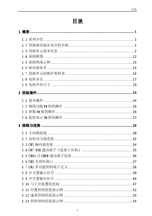
目录1 概要 (1)1.1系列介绍 (1)1.2伺服驱动器各部分的名称 (1)1.3伺服单元基本信息 (2)1.4系统框图 (12)1.5系统构成示例 (13)1.6驱动器命名 (14)1.7伺服单元的维护和检查 (16)1.8电机命名 (17)1.9电机外形尺寸 (19)2 面板操作 (24)2.1基本操作 (24)2.2辅助功能F N组的操作 (26)2.3参数P N组的操作 (26)2.4监控显示U N组的操作 (27)3 接线与连接 (28)3.1主回路接线 (28)3.2电机动力线连接 (32)3.3CN2编码器连接 (34)3.4CN7USB通讯端子(连接上位机) (35)3.5CN6A及CN6B通讯端子连接 (36)3.6CN5全闭环端口 (37)3.7CN1多功能控制端子定义 (38)3.8开关量输入信号 (39)3.9开关量输出信号 (44)3.10与上位装置的连接 (47)3.11位置控制的连接示例 (52)3.12速度控制的连接示例 (53)3.13转矩控制的连接示例 (54)3.14再生电阻连接 (55)3.15噪音和高次谐波对策 (56)4 试运行 (57)4.1试运行前的检查和注意事项 (57)4.2JOG试运行 (57)5 运行 (58)5.1基本功能 (58)5.2位置模式 (68)5.3速度模式 (80)5.4转矩模式 (88)5.5混合控制方式选择 (91)5.6其他输出信号 (94)5.7时序 (96)5.8全闭环控制 (98)6 调整 (105)6.1关于调整 (105)6.2鲁棒控制 (107)6.3惯量辨识 (109)6.4智能设定 (110)6.5带宽设定 (114)6.6手动调整功能 (117)7 辅助功能 (127)7.1辅助功能一览 (127)7.2显示警报记录(F N000) (127)7.3清除警报记录(F N001) (128)7.4软件复位(F N002) (128)7.5恢复出厂参数(F N003) (129)7.6JOG运行(F N005) (130)7.7程序JOG运行(F N006) (131)7.8指令偏置的自动调整(F N100) (132)7.9速度指令偏置手动调整(F N101) (132)7.10转矩指令偏置手动调整(F N102) (133)7.11电流偏置自动调整(F N103) (133)7.12电流偏置手动调整(F N104) (134)7.13对振动检出的检出值初始化(F N105) (135)7.14带宽设定(F N303) (136)7.15E ASY FFT(F N401) (136)7.16在线振动监视(F N402) (137)8 原点回归与内部位置 (138)8.1原点回归功能说明 (138)8.2原点回归功能码 (141)8.3原点回归方式 (143)9 内部位置 (180)9.1点位控制功能码参数设置 (180)9.2点位控制相关功能码 (181)9.3点位功能运行参数 (194)9.4插断功能 (196)9.5重叠功能 (200)9.6停止功能 (200)9.7跳转功能 (201)9.8点动功能 (202)10 功能码说明 (204)10.1P N0组基本控制 (204)10.2P N1组增益类 (211)10.3P N2组位置类 (218)10.4P N3组速度类 (224)10.5P N4组转矩类 (226)10.6P N5组点动相关 (228)10.7P N6组开关量配置相关 (229)10.8P N7组扩展相关 (233)10.9P N8组内部位置/原点回归参数 (234)11 监视显示 (242)12 故障码及对策 (247)12.1故障码 (247)12.2警告码 (253)13 通讯 (254)13.1通信介绍 (254)13.2RS485通信协议说明 (254)13.3通信帧结构 (254)13.4命令码及通信数据描述 (255)13.5通信帧错误校验方式 (257)13.6错误消息的回应 (258)14 上位调试相关 (259)14.1系统要求 (259)14.2主界面 (260)14.3功能介绍 (261)14.4实时监测 (263)14.5辅助功能介绍 (264)14.6数字示波器 (272)14.7其它 (273)1 概要1.1 系列介绍SD700系列伺服系统主要用于需要“高速、高频度、高定位精度”的场合,该伺服单元拥有3kHZ 速度环响应带宽,可以在最短的时间内最大限度地发挥机器性能,有助于提高生产效率,通讯方面支持EtherCAT,Profinet,MECHATROLINK-II,MECHATROLINK-III,CANopen,RS-485等市面上主流的现场总线,同时也具有全闭环,电子凸轮,追飞剪,龙门同步等非标应用功能,通过USB可连接电脑上位机进行调试,方便快捷。
YJB补偿式微压计说明书完整板

YJB-1500/2500型补偿式微压计沪制01100013使用说明书一、用途:补偿式微压计用于测量非腐蚀性气体的微小压力,负压力及压力差,也可用来效准其他压力计,可供实验室和计量单位使用。
二、主要技术参数:1、测量范围、基本误差型号YJB-1500 YJB-2500规格-1500~+1500 Pa -2500~+2500Pa最小分度值0.01mm 0.01mm基本误差±0.8 Pa 在-1.5~+1.5KPa范围内:±0.8 Pa 在-2.5~<-1.5KPa范围内:±1.3 Pa 或在>1.5~2.5KPa外形尺寸230×322mm 230×422mm重量6Kg 9Kg三、结构简述:补偿微压计由微调部分、水准观测部分、反光镜部分急外壳部分组成。
◎微调部分:由刻有200等分的微调盘固定在长螺杆上,长螺杆带动蓄水筒作上升或下降运动,在水匣静压接嘴上装有示度滑块,示度滑块沿示值标尺上下移动指出蓄水筒的位移高度。
◎水准观测部分:在观测筒内装有水准头,以观测由动压管受压力后观测筒内液面的变化。
◎反光镜部分:由一个反光镜固定在镜壳上,反光镜面反射观测量筒内的水准头与液面的接触情况,使水准头尖与其倒影的影尖相接表示微压计读数调整“基点”。
◎外壳部分:由壳体及横担支持长螺杆,在壳体上装有水平泡及调节螺钉,以调节微压计的螺杆及动压管的垂直。
四、使用方法:1、调整:(1)将微压计放置在工作台上,调整调节螺钉,使仪器处于水平(观察水准泡的气泡在黑圆圈中间)。
(2)转动微调盘,将微调盘与示值滑块均调到“O”位,旋下动压管密封螺钉,逐渐灌入蒸馏水,同时从反光镜上观察水准头与液面基本相接时,暂停加水,再旋紧顶端密封螺钉。
然后缓慢挑拨微调盘,使蓄水筒上升下降数次,以排尽连接管内的空气,经上述过程后,再调动动压管调节螺母,使完全达到液面与针尖相切要求(经3~5min后能稳定不变)。
YJ240BFYJ245YJ245DYJ200YJ275曳引机制动器的拆解与清洁
YJ240BFYJ245YJ245DYJ200YJ275曳引机制动器的拆解与清洁YJ240B、FYJ245、YJ245D、YJ200、YJ275是常见的曳引机型号,它们在电梯行业中被广泛使用。
曳引机制动器是电梯的重要组成部分之一,负责控制电梯的运行和停止。
为了确保电梯的运行安全和稳定性,定期拆解和清洁曳引机制动器是必要的。
下面将详细介绍曳引机制动器的拆解与清洁步骤。
步骤一:准备工作1.断开电梯的电源,确保工作安全。
2.准备必要的工具和清洁材料,如扳手、刷子、清洁剂等。
3.查看电梯制造商提供的曳引机制动器拆解与清洁手册,了解具体操作流程和注意事项。
步骤二:拆解曳引机制动器1.拆下曳引机制动器的外壳,通常需要使用扳手或螺丝刀来拆卸螺丝。
2.将外壳拆下后,可以看到内部的零件和组件。
注意保持清洁,并避免损坏零件。
步骤三:清洁曳引机制动器1.用刷子或者空气压缩机将曳引机制动器的内部灰尘和污垢清除干净。
灰尘和污垢可能会影响机器的正常运行。
2.使用专用的清洁剂,按照制造商提供的使用说明,对曳引机制动器进行清洁。
确保清洁剂完全覆盖到每个部分,并使用刷子清洁需要的地方。
3.清洗过程中小心操作,避免弄湿机器的内部,以免损坏电气元件或导致电击事故。
步骤四:检查曳引机制动器零件1.检查曳引机制动器内部的各个零件,如制动片、摩擦衬垫等,确保其没有损坏或磨损。
2.检查曳引机制动器的弹簧和连接件,确保其没有失效。
3.如果发现零件有损坏或磨损,及时更换,确保曳引机制动器的正常运行。
步骤五:组装曳引机制动器1.清洁和检查曳引机制动器的各个部分后,按照逆序将其重新组装。
确保螺丝紧固牢固,零件安装正确。
2.组装完成后,再次检查曳引机制动器的各个部分和螺丝是否安装正确,以避免出现故障。
步骤六:测试和调试1.将曳引机制动器安装回电梯中,并连接好电源。
2.打开电梯的电源,进行测试和调试。
确保曳引机制动器的正常运行和制动效果。
以上是拆解和清洁YJ240B、FYJ245、YJ245D、YJ200、YJ275曳引机制动器的详细步骤。
局域网组建项目实战项目一

脑,将来还有可能会增加,现想把这些电脑组建 成局域网,以便于实现磁盘共享、刻录机共享、 联网游戏和将来共享上网等等。
:// hd8go :// hd88go :// sj93 :// oemgc / :// 189288 :// hzp580 :// yjoem
▪ 类型:以太网(Ethernet)、令牌环网(Token Ring)、 光纤分布数据接口网(FDDI)、异步传输模式网(ATM) 和无线局域网(WLAN)
1.1.6 知识点
❖对等网络和基于服务器的网络 ▪ 对等网络 网络内所有的计算机都是平等的,没有主次之分, 每台计算机可以独立使用,也可以互相共享资源。 一般存在于家庭和办公室等小型的局域网。 特点:
:// oemdg / :// xcdnpx / :// skfjk :// oemdg :// xcdnpx / :// dgxcdn :// dgxcpx :// xcwxpx
1.1.2 制作双绞线
❖实施步骤 步骤1:双绞线的剥皮 步骤2:双绞线的排序 步骤3:水晶头压制 步骤4:双绞线测试 步骤5:网卡和双绞线的安装
任务1.2 多机组网
任务1.2 多机组网
❖ 能力目标
▪ 会制作和安装双绞线 ▪ 会安装交换机 ▪ 会配置TCP/IP协议 ▪ 会使用命令测试网络
❖ 知识目标
▪ 了解网络设备 ▪ 掌握集线器的原理 ▪ 掌握交接机的原理 ▪ 了解网络协议 ▪ 了解TCP/IP协议 ▪ 熟悉IP编址技术
1.2.1 任务概述
❖ ping命令:可以检查本计算机和网络上另一台计算 机的连通性
:// hd8go :// hd88go :// sj93 :// oemgc / :// 189288 :// hzp580 :// yjoem
北方工具+设备公司 500-LB. 水力可调动车说明书

22
Hex Cap Bolt
23
Bearing Cover
24
Needle Bearing
25
Brake Foot Pedal
26
Brake Slice
27
Wheel
28
Set Nut
29
Shaft
30
C-ring
31
Cyliner
32
C-ring
33
Joint Shaft
34
Big Spring
35
cause accidents. · Do not use your tool where there is a risk of causing a fire or an explosion; e.g. in the
presence of flammable liquids, gasses, or dust. Power tools create sparks, which may ignite the dust or fumes. · Keep children and bystanders away while operating a power tool. Distractions can cause you to lose control, so visitors should remain at a safe distance from the work area. · Be aware of all power lines, electrical circuits, water pipes and other mechanical hazards in your work area, particularly those hazards below the work surface hidden from the operator's view that may be unintentionally contacted and may cause personal harm or property damage. · Be alert of your surroundings. Using power tools in confined work areas may put you Dangerously close to cutting tools and rotating parts.
Festo YJKP 应用手册说明书

Application NoteYJKP - Manual movementDescription how to use manual functions YJKP100263Title ..................................................................................................................... AppNote YJKP Manual movement Version ............................................................................................................................................................. 1.10 Document no. . (100263)Original .................................................................................................................................................................en Author ............................................................................................................................................................. F esto Last saved ............................................................................................................................................ 05.09.2019Copyright NoticeThis documentation is the intellectual property of Festo AG & Co. KG, which also has the exclusive copyright. Any modification of the content, duplication or reprinting of this documentation as well as distribution to third par-ties can only be made with the express consent of Festo AG & Co. KG.Festo AG & Co KG reserves the right to make modifications to this document in whole or in part. All brand and product names are trademarks or registered trademarks of their respective owners.Legal NoticeHardware, software, operating systems and drivers may only be used for the applications described and only in conjunction with components recommended by Festo AG & Co. KG.Festo AG & Co. KG does not accept any liability for damages arising from the use of any incorrect or incomplete information contained in this documentation or any information missing therefrom.Defects resulting from the improper handling of devices and modules are excluded from the warranty.The data and information specified in this document should not be used for the implementation of safety func-tions relating to the protection of personnel and machinery.No liability is accepted for claims for damages arising from a failure or functional defect. In other respects, the regulations with regard to liability from the terms and conditions of delivery, payment and use of software of Festo AG & Co. KG, which can be found at and can be supplied on request, shall apply.All data contained in this document do not represent guaranteed specifications, particularly with regard to func-tionality, condition or quality, in the legal sense.The information in this document serves only as basic information for the implementation of a specific, hypo-thetical application and is in no way intended as a substitute for the operating instructions of the respective manufacturers and the design and testing of the respective application by the user.The operating instructions for Festo products can be found at /sp .Users of this document (application note) must verify that all functions described here also work correctly in the application. By reading this document and adhering to the specifications contained therein, users are also solely responsible for their own application.(Festo AG & CO. KG, D-73726 Esslingen, 2019)Internet: Table of contents1Components/Software used (5)1.1Application description (5)2Prerequisites (6)3Manual control (8)3.1Via WebVisu (8)3.2Via Host PLC (13)Components/Software used 1Components/Software usedTable 1.1: 1Components/Software used1.1Application descriptionThis application note describes how to use manual movement and tare function via WebVisu and Host. Application Note – YJKP Manual movement – 1.10 Page 5 of 14Prerequisites2PrerequisitesOpen a browser and start the WebVisu of the YJKP.In Browser: <IP of the CECC-X>:8080/servo_press_kit.htmThe visualization of the servo-press kit is opened with 4 tabs :•Commissioning , Program : Not active•Operation , Diagnosis: ActiveClick on Login to active the commissioning and program tabs. A new pop-up window appears and a password must be entered to login.Default password: User name: AdminPassword: ServoPressKitPage 6 of 14 Application Note – YJKP Manual movement – 1.10PrerequisitesApplication Note – YJKP Manual movement – 1.10Page 7 of 141. go to the commissioning tab -> system settings and set the control to WebVisu.2. In commissioning tab check, if the hardware is configured successfully (= Green) and the system is homed (=Green). You will see a Ready in the bottom left corner.Note :• For further information about hardware configuration and homing, please read AppNote Servo Press.Kit YJKP Hardware Configuration and AppNote Servo Press Kit YJKP Homing.3. Activate the servo press system with input X17.4.2 . Output X20.5.1 will turn true.4. Set the system mode to manual (Input X3.1 high, Input X3.2 low).The servo press is now ready for a manual operation.Manual controlPage 8 of 14 Application Note – YJKP Manual movement – 1.103 Manual control3.1 Via WebVisuThe manual control panel consists of the following parts:1. C ylinder status• Release(d): activation status of the system. • Actual force: current force value (N). • Actual position: current position of the cylinder (mm). • Actual velocity: current speed of the cylinder (mm/s).2. Tare: This function is used to manipulate the actual force value.While commissioning the YJKP, you will notice that the actual force value in WebVisu might not be equal zero ( as shown in the below figure ). This value is mainly influenced by the mounting position ( horizon-tal or vertical ) and the weight of all mounted parts at the load cell. Thus when you need to press with a certain amount of force, the actual force needs to be reset before starting the pressing process.How to use it:• Check tare : Activate/Deactivate this function.•Offset :This value is added to the actual force value.Manual controlApplication Note – YJKP Manual movement – 1.10Page 9 of 14Example:Actual force is 18.38 N, as shown in the previous figure.After activating the tare function and with an offset of 0 N, the new actual force will be round about 0 N.3. Motion : The control panel of the manual movement.There are three methods in YJKP system to do a manual movement:I. Absolute movement:It is a method to move the cylinder to a target position based on the homing position of the cylinder.1.Move : starts the movement the cylinder.2. Velocity : Cylinder speed when moving to the target position.3. Position : target position(mm)4. Stop : stops the movement of the cylinder.Example:In this example the …Absolute “ method will be used to move the cylinder to the posi-tion 20 mm .Set these values:• Motion : Absolute • Velocity : 5 mm/s • Position : 20 mmManual controlPage 10 of 14Application Note – YJKP Manual movement – 1.10Startposition: Actual position = 7 mmClick on “Move ” button: The Cylinder will move from absolute position 7mm to absolute position 20mm (distance of 13mm) at speed of 5 mm/s. New actual position= 20 mm.I.Relative movement:I t is a method to move the cylinder a certain distance based on the current position of the cylinder.1.Move : starts the movement of the cylinder.2. Velocity : Cylinder speed when moving to the target position.3. Distance :target distance (mm)4.Stop : stops the movement of the cylinder.Example:In this example the …Relative“ method will be used to move the cylinder 20 mm .Set these values:•Motion : Relative•Velocity : 5 mm/s•Distance : 20 mmStartposition: Actual position = 7 mmClick on “Move” button: The cylinder will move a distance of 20mm (from absoluteposition 7mm to absolute position 27mm). New Actual posi-tion = 27 mm.II.Jog movement:It is a method to move the cylinder as long as you hold the movement buttons.1.+ : moves the cylinder in the positive direction.2.- : moves the cylinder in the negative direction.3.Velocity :Cylinder speed when moving.Example:Set this velocity value:•Velocity : 5 mm/sClick on the “+ / – buttons” to move the cylinder in the positive/negative directions asshown in the figure :3.2Via Host PLCThis chapter will not describe all steps in particular, since they are basically the same like with the WebVisu (please refer to previous chapter).It shows the needed function blocks and required inputs and outputs.1.FB_ConnectRequired inputs:•xEnable := true;•enTargetComMode := 1;Required outputs:•xActive := true;•enActualComMode := 1;•xConnected := true;2.FB_ManualRequired inputs:•xEnable := true;•xEnableSystem := True;•xAbort :=True ;•xTare:= True/False; (manipulates the force value).•rTargetOffsetForceSensor:=; (Target offset of the force sensor).•enTargetPosMode:=;(Target position mode0x00 = Jog0x01 = Move absolute0x02 = Move relative ).•rTargetMotionVelocity:= ; (Cylinder speed when moving to the target position).•rTargetMotionPositionDistance:=; (position/distance when using absolute/relativemethod)•xMove:= True/False; (move the cylinder when using Absolute/Relativemethods).•xStopMove:= True/False; (stops the movement of the cylinder).•xJogPos:= True /False; (moves the cylinder in the positive direction).•xJogNeg:= True/ False ; (moves the cylinder in the negative direction).Required outputs:•xActive := true;•xSystemEnabled:=True;•xSystemIsHomed :=True;•。
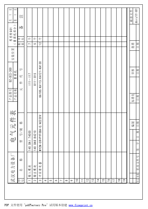
dbs-yjb-300
页 页
序 号
名
称
号 /规
格
备
注
1 蜂鸣器
AD16-22SM/r31
2 转换开关
XB2-BD25C
3 钥匙转换开关
XB2-BG21C
4 蘑菇按钮
ZB2-BZ105C+ZB2BC4C
5 平头按钮
XB2-BA42C
6 带灯转换开关
ZB2BK123+ZB2BWM31C
7 带灯按钮
XB2BW33M1C
8 指示灯
7
辅助触头
8 断路器
C65N 17925
单 极 2A 三 极 10A 5 5~ 8A 三 极 25-40A 30~ 40A 两 极 32A 三 极 9-14A 9~ 13A 臂架 油 箱加热器 1 个 2 3KW( 220V) 1 个
9 断路器
C65N 17953+26924
10 交 流 接 触 器
页 页
序 号
名
称
备
注
1 轴流风机
UF25GC23-H( 配 MG-25护 网 )
2
3 重调机制动电阻
PRU-30/7(不 锈 钢 电 阻 )
4
5
6
7
8
9
பைடு நூலகம்10
11
PDF 文件使用 "pdfFactory Pro" 试用版本创建
12
13
14
15
16
17
18
19 编制
字 日 期 日期
C65N 17943
10 交 流 接 触 器
LC1-D1210M5C
11 重 调 机 输 入 电 抗 器 1321-3R750-B
叉车维修手册
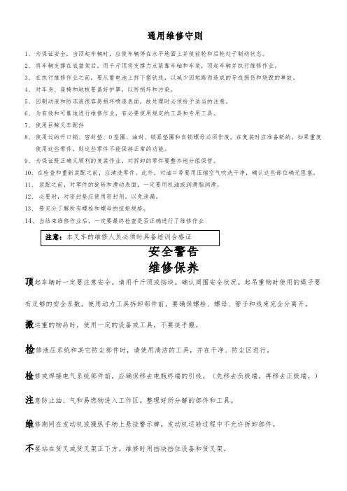
通用维修守则1、为保证安全,当顶起车辆时,应使车辆停在水平地面上并使前轮和后轮处于制动状态。
2、将车辆支撑在底盘架后,用千斤顶将支撑力点紧靠车轴和车架,顶起车辆并执行维修作业。
3、在执行维修作业之前,要从蓄电池上拆下搭铁线,以减少因短路而造成的导线损伤和烧毁的事故。
4、对车身、座椅和地板要盖好护罩,以防损坏和污染。
5、因制动液和防冻液很容易损坏喷漆表面,故处理时必须给予适当的注意。
6、为有效和可靠地进行维修作业,有必要使用规定的工具和专用工具。
7、使用巨鲸叉车配件8、9、1011、12、13、14、顶搬检检修或焊接电气系统部件前,应确保移去电瓶终端的引线。
(先移去负极端,再移去正极端。
)注意防止油、气和易燃物进入工作区。
整理好所分解的部件和工具。
维修期间在发动机或操纵手柄上悬挂警示牌。
发动机运转过程中不允许拆卸部件。
不要站在货叉或货叉架正下方。
维修时用挡块挡住设备和货叉架。
维修工具按次序摆放,定期检查,正确使用。
在通风不良的房间(车间),发动机不宜较长时间运转。
一动力系统H系列柴油动力叉车可分别采用国产490BPG柴油机,进口五十铃C240PKJ型柴油机作为动力,通过飞轮与离合器/变扭器相连,将动力传递给传动系统。
有关发动机的性能、结构、使用及保养,请参阅随机出厂的柴油机说明书。
叉车的动力配置离合器主要由压盘总成、摩擦片、离合器壳、分离轴承组成。
压盘用螺栓固定在发动机飞轮上,踩下离合器踏板操作分离叉使摩擦片与飞轮分离。
离合器膜片顶端与分离轴承端面间隙在离合器接合状态时为2-3.5mm,由于叉车经常处于加速和换向工况,摩擦片磨损较快,应经常检查调查此间隙。
图2-1离合器1、螺栓2、垫圈3、离合器壳4、橡胶垫5、螺母6、垫圈7、分离叉护罩8、压板9、垫圈10、螺栓11、螺母12、支承螺栓13、弹簧挡圈14、分离叉15、分离轴承套筒16、分离轴承17、离合器压盘及盖总成18、离合器摩擦片总成19、垫圈20、螺栓2.1.3更换摩擦片总成A、踩下离合踏板,使摩擦片脱开;B、逆时针转动变速箱上端滑动螺杆,使主动轴缩进变速箱内;C、取下压盘壳螺栓,使其与飞轮脱开,取出旧摩擦片总成;D、装进新摩擦片总成,应注意摩擦片盘毂花键套伸出较长的一端朝变速箱一侧;H系列2-3t机械传动叉车采用引进技术JDS30型机械变速箱。
- 1、下载文档前请自行甄别文档内容的完整性,平台不提供额外的编辑、内容补充、找答案等附加服务。
- 2、"仅部分预览"的文档,不可在线预览部分如存在完整性等问题,可反馈申请退款(可完整预览的文档不适用该条件!)。
- 3、如文档侵犯您的权益,请联系客服反馈,我们会尽快为您处理(人工客服工作时间:9:00-18:30)。
目录:
一、产品说明
二、软件使用说明
2.1、软件界面
2.2、设置参数
2.3、输入显示数据
三、包装清单
四、技术支持
一、产品说明
适用范围:单色
场扫描频率:>120Hz (最大面积)
最大控制点:64 X 1024
存储空间:4M bits
扫描方式:软件设置1/16扫描、1/8扫描、1/4扫描支持时钟:采用万年历,模拟表盘/中英文时钟
支持开关:软件实现屏幕显示开关
通讯波特率:38400
通讯方式:RS232
通讯距离:120米
供电电源:5V(范围4.5V~6V)
最大功率:< 0.5W
环境温度:-30℃~70℃
二、软件使用说明
2.1、软件界面
2.2、设置参数
1、打开软件,进入软件主界面。
2、选择设置—>设置屏参,进入参数设置界面
可在此界面设置串口号和LED显示屏尺寸。
波特率为固定的38400。
3、连接好通讯线,点击“加载”,屏幕参数发送给显示屏。
4、加载成功后会提示
,否则提示
2.3、输入显示数据
1、各种参数设置完毕后进入主界面。
在“文字输入”框里输入要显示的数据。
如需多行显示,敲回车键换行。
2、设置要显示数据的字体大小
3、选择时钟模式
4、选择显示方式、显示速度、停留时间
6、连接好通讯线,点击“发送”,数据将发送给显示屏(数据量较大时,数据传送会占用较
长时间,请耐心等待)。
三、包装清单
1、一块LED显示屏控制卡;
2、一只在板纽扣电池;
3、一张置有控制系统软件及用户手册的CD光盘。
四、技术支持
感谢您购买LED条屏控制卡,如果您遇到有关我们产品的任何质量问题或技术问题,请及时和您的直接服务商联系。
