7838C_Cora Aromatics_CCR_Platforming_Wang_04_24 Chinese
Tektronix MDO3000 Series 数字多功能作业仪用户指南说明书
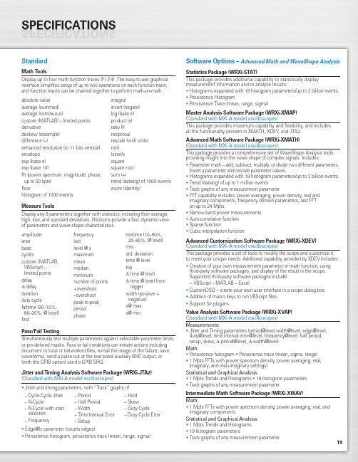
19StandardMath ToolsDisplay up to four math function traces (F1-F4). The easy-to-use graphical interface simplifies setup of up to two operations on each function trace;and function traces can be chained together to perform math-on-math.absolute value integralaverage (summed)invert (negate)average (continuous)log (base e)custom (MATLAB) – limited points product (x)derivativeratio (/)deskew (resample)reciprocaldifference (–)rescale (with units)enhanced resolution (to 11 bits vertical)roof envelope (sinx)/x exp (base e)square exp (base 10)square root fft (power spectrum, magnitude, phase,sum (+)up to 50 kpts) trend (datalog) of 1000 events floorzoom (identity)histogram of 1000 eventsMeasure ToolsDisplay any 6 parameters together with statistics, including their average,high, low, and standard deviations. Histicons provide a fast, dynamic view of parameters and wave-shape characteristics.Pass/Fail TestingSimultaneously test multiple parameters against selectable parameter limits or pre-defined masks. Pass or fail conditions can initiate actions including document to local or networked files, e-mail the image of the failure, save waveforms, send a pulse out at the rear panel auxiliary BNC output, or (with the GPIB option) send a GPIB SRQ.Jitter and Timing Analysis Software Package (WRXi-JTA2)(Standard with MXi-A model oscilloscopes)•Jitter and timing parameters, with “Track”graphs of •Edge@lv parameter (counts edges)• Persistence histogram, persistence trace (mean, range, sigma)Software Options –Advanced Math and WaveShape AnalysisStatistics Package (WRXi-STAT)This package provides additional capability to statistically display measurement information and to analyze results:• Histograms expanded with 19 histogram parameters/up to 2 billion events.• Persistence Histogram• Persistence Trace (mean, range, sigma)Master Analysis Software Package (WRXi-XMAP)(Standard with MXi-A model oscilloscopes)This package provides maximum capability and flexibility, and includes all the functionality present in XMATH, XDEV, and JTA2.Advanced Math Software Package (WRXi-XMATH)(Standard with MXi-A model oscilloscopes)This package provides a comprehensive set of WaveShape Analysis tools providing insight into the wave shape of complex signals. Includes:•Parameter math – add, subtract, multiply, or divide two different parameters.Invert a parameter and rescale parameter values.•Histograms expanded with 19 histogram parameters/up to 2 billion events.•Trend (datalog) of up to 1 million events•Track graphs of any measurement parameter•FFT capability includes: power averaging, power density, real and imaginary components, frequency domain parameters, and FFT on up to 24 Mpts.•Narrow-band power measurements •Auto-correlation function •Sparse function• Cubic interpolation functionAdvanced Customization Software Package (WRXi-XDEV)(Standard with MXi-A model oscilloscopes)This package provides a set of tools to modify the scope and customize it to meet your unique needs. Additional capability provided by XDEV includes:•Creation of your own measurement parameter or math function, using third-party software packages, and display of the result in the scope. Supported third-party software packages include:– VBScript – MATLAB – Excel•CustomDSO – create your own user interface in a scope dialog box.• Addition of macro keys to run VBScript files •Support for plug-insValue Analysis Software Package (WRXi-XVAP)(Standard with MXi-A model oscilloscopes)Measurements:•Jitter and Timing parameters (period@level,width@level, edge@level,duty@level, time interval error@level, frequency@level, half period, setup, skew, Δ period@level, Δ width@level).Math:•Persistence histogram •Persistence trace (mean, sigma, range)•1 Mpts FFTs with power spectrum density, power averaging, real, imaginary, and real+imaginary settings)Statistical and Graphical Analysis•1 Mpts Trends and Histograms •19 histogram parameters •Track graphs of any measurement parameterIntermediate Math Software Package (WRXi-XWAV)Math:•1 Mpts FFTs with power spectrum density, power averaging, real, and imaginary componentsStatistical and Graphical Analysis •1 Mpts Trends and Histograms •19 histogram parameters•Track graphs of any measurement parameteramplitude area base cyclescustom (MATLAB,VBScript) –limited points delay Δdelay duration duty cyclefalltime (90–10%, 80–20%, @ level)firstfrequency lastlevel @ x maximum mean median minimumnumber of points +overshoot –overshoot peak-to-peak period phaserisetime (10–90%, 20–80%, @ level)rmsstd. deviation time @ level topΔ time @ levelΔ time @ level from triggerwidth (positive + negative)x@ max.x@ min.– Cycle-Cycle Jitter – N-Cycle– N-Cycle with start selection – Frequency– Period – Half Period – Width– Time Interval Error – Setup– Hold – Skew– Duty Cycle– Duty Cycle Error20WaveRunner WaveRunner WaveRunner WaveRunner WaveRunner 44Xi-A64Xi-A62Xi-A104Xi-A204Xi-AVertical System44MXi-A64MXi-A104MXi-A204MXi-ANominal Analog Bandwidth 400 MHz600 MHz600 MHz 1 GHz 2 GHz@ 50 Ω, 10 mV–1 V/divRise Time (Typical)875 ps500 ps500 ps300 ps180 psInput Channels44244Bandwidth Limiters20 MHz; 200 MHzInput Impedance 1 MΩ||16 pF or 50 Ω 1 MΩ||20 pF or 50 ΩInput Coupling50 Ω: DC, 1 MΩ: AC, DC, GNDMaximum Input Voltage50 Ω: 5 V rms, 1 MΩ: 400 V max.50 Ω: 5 V rms, 1 MΩ: 250 V max.(DC + Peak AC ≤ 5 kHz)(DC + Peak AC ≤ 10 kHz)Vertical Resolution8 bits; up to 11 with enhanced resolution (ERES)Sensitivity50 Ω: 2 mV/div–1 V/div fully variable; 1 MΩ: 2 mV–10 V/div fully variableDC Gain Accuracy±1.0% of full scale (typical); ±1.5% of full scale, ≥ 10 mV/div (warranted)Offset Range50 Ω: ±1 V @ 2–98 mV/div, ±10 V @ 100 mV/div–1 V/div; 50Ω:±400mV@2–4.95mV/div,±1V@5–99mv/div,1 M Ω: ±1 V @ 2–98 mV/div, ±10 V @ 100 mV/div–1 V/div,±10 V @ 100 mV–1 V/div±**********/div–10V/div 1 M Ω: ±400 mV @ 2–4.95 mV/div, ±1 V @5–99 mV/div, ±10 V @ 100 mV–1 V/div,±*********–10V/divInput Connector ProBus/BNCTimebase SystemTimebases Internal timebase common to all input channels; an external clock may be applied at the auxiliary inputTime/Division Range Real time: 200 ps/div–10 s/div, RIS mode: 200 ps/div to 10 ns/div, Roll mode: up to 1,000 s/divClock Accuracy≤ 5 ppm @ 25 °C (typical) (≤ 10 ppm @ 5–40 °C)Sample Rate and Delay Time Accuracy Equal to Clock AccuracyChannel to Channel Deskew Range±9 x time/div setting, 100 ms max., each channelExternal Sample Clock DC to 600 MHz; (DC to 1 GHz for 104Xi-A/104MXi-A and 204Xi-A/204MXi-A) 50 Ω, (limited BW in 1 MΩ),BNC input, limited to 2 Ch operation (1 Ch in 62Xi-A), (minimum rise time and amplitude requirements applyat low frequencies)Roll Mode User selectable at ≥ 500 ms/div and ≤100 kS/s44Xi-A64Xi-A62Xi-A104Xi-A204Xi-A Acquisition System44MXi-A64MXi-A104MXi-A204MXi-ASingle-Shot Sample Rate/Ch 5 GS/sInterleaved Sample Rate (2 Ch) 5 GS/s10 GS/s10 GS/s10 GS/s10 GS/sRandom Interleaved Sampling (RIS)200 GS/sRIS Mode User selectable from 200 ps/div to 10 ns/div User selectable from 100 ps/div to 10 ns/div Trigger Rate (Maximum) 1,250,000 waveforms/secondSequence Time Stamp Resolution 1 nsMinimum Time Between 800 nsSequential SegmentsAcquisition Memory Options Max. Acquisition Points (4 Ch/2 Ch, 2 Ch/1 Ch in 62Xi-A)Segments (Sequence Mode)Standard12.5M/25M10,00044Xi-A64Xi-A62Xi-A104Xi-A204Xi-A Acquisition Processing44MXi-A64MXi-A104MXi-A204MXi-ATime Resolution (min, Single-shot)200 ps (5 GS/s)100 ps (10 GS/s)100 ps (10 GS/s)100 ps (10 GS/s)100 ps (10 GS/s) Averaging Summed and continuous averaging to 1 million sweepsERES From 8.5 to 11 bits vertical resolutionEnvelope (Extrema)Envelope, floor, or roof for up to 1 million sweepsInterpolation Linear or (Sinx)/xTrigger SystemTrigger Modes Normal, Auto, Single, StopSources Any input channel, External, Ext/10, or Line; slope and level unique to each source, except LineTrigger Coupling DC, AC (typically 7.5 Hz), HF Reject, LF RejectPre-trigger Delay 0–100% of memory size (adjustable in 1% increments, or 100 ns)Post-trigger Delay Up to 10,000 divisions in real time mode, limited at slower time/div settings in roll modeHold-off 1 ns to 20 s or 1 to 1,000,000,000 events21WaveRunner WaveRunner WaveRunner WaveRunner WaveRunner 44Xi-A 64Xi-A 62Xi-A104Xi-A 204Xi-A Trigger System (cont’d)44MXi-A64MXi-A104MXi-A204MXi-AInternal Trigger Level Range ±4.1 div from center (typical)Trigger and Interpolator Jitter≤ 3 ps rms (typical)Trigger Sensitivity with Edge Trigger 2 div @ < 400 MHz 2 div @ < 600 MHz 2 div @ < 600 MHz 2 div @ < 1 GHz 2 div @ < 2 GHz (Ch 1–4 + external, DC, AC, and 1 div @ < 200 MHz 1 div @ < 200 MHz 1 div @ < 200 MHz 1 div @ < 200 MHz 1 div @ < 200 MHz LFrej coupling)Max. Trigger Frequency with400 MHz 600 MHz 600 MHz 1 GHz2 GHzSMART Trigger™ (Ch 1–4 + external)@ ≥ 10 mV@ ≥ 10 mV@ ≥ 10 mV@ ≥ 10 mV@ ≥ 10 mVExternal Trigger RangeEXT/10 ±4 V; EXT ±400 mVBasic TriggersEdgeTriggers when signal meets slope (positive, negative, either, or Window) and level conditionTV-Composite VideoT riggers NTSC or PAL with selectable line and field; HDTV (720p, 1080i, 1080p) with selectable frame rate (50 or 60 Hz)and Line; or CUSTOM with selectable Fields (1–8), Lines (up to 2000), Frame Rates (25, 30, 50, or 60 Hz), Interlacing (1:1, 2:1, 4:1, 8:1), or Synch Pulse Slope (Positive or Negative)SMART TriggersState or Edge Qualified Triggers on any input source only if a defined state or edge occurred on another input source.Delay between sources is selectable by time or eventsQualified First In Sequence acquisition mode, triggers repeatedly on event B only if a defined pattern, state, or edge (event A) is satisfied in the first segment of the acquisition. Delay between sources is selectable by time or events Dropout Triggers if signal drops out for longer than selected time between 1 ns and 20 s.PatternLogic combination (AND, NAND, OR, NOR) of 5 inputs (4 channels and external trigger input – 2 Ch+EXT on WaveRunner 62Xi-A). Each source can be high, low, or don’t care. The High and Low level can be selected independently. Triggers at start or end of the patternSMART Triggers with Exclusion TechnologyGlitch and Pulse Width Triggers on positive or negative glitches with widths selectable from 500 ps to 20 s or on intermittent faults (subject to bandwidth limit of oscilloscope)Signal or Pattern IntervalTriggers on intervals selectable between 1 ns and 20 sTimeout (State/Edge Qualified)Triggers on any source if a given state (or transition edge) has occurred on another source.Delay between sources is 1 ns to 20 s, or 1 to 99,999,999 eventsRuntTrigger on positive or negative runts defined by two voltage limits and two time limits. Select between 1 ns and 20 sSlew RateTrigger on edge rates. Select limits for dV, dt, and slope. Select edge limits between 1 ns and 20 s Exclusion TriggeringTrigger on intermittent faults by specifying the normal width or periodLeCroy WaveStream Fast Viewing ModeIntensity256 Intensity Levels, 1–100% adjustable via front panel control Number of Channels up to 4 simultaneouslyMax Sampling Rate5 GS/s (10 GS/s for WR 62Xi-A, 64Xi-A/64MXi-A,104Xi-A/104MXi-A, 204Xi-A/204MXi-A in interleaved mode)Waveforms/second (continuous)Up to 20,000 waveforms/secondOperationFront panel toggle between normal real-time mode and LeCroy WaveStream Fast Viewing modeAutomatic SetupAuto SetupAutomatically sets timebase, trigger, and sensitivity to display a wide range of repetitive signalsVertical Find ScaleAutomatically sets the vertical sensitivity and offset for the selected channels to display a waveform with maximum dynamic range44Xi-A 64Xi-A 62Xi-A104Xi-A 204Xi-A Probes44MXi-A 64MXi-A104MXi-A 204MXi-AProbesOne Passive probe per channel; Optional passive and active probes available Probe System; ProBus Automatically detects and supports a variety of compatible probes Scale FactorsAutomatically or manually selected, depending on probe usedColor Waveform DisplayTypeColor 10.4" flat-panel TFT-LCD with high resolution touch screenResolutionSVGA; 800 x 600 pixels; maximum external monitor output resolution of 2048 x 1536 pixelsNumber of Traces Display a maximum of 8 traces. Simultaneously display channel, zoom, memory, and math traces Grid StylesAuto, Single, Dual, Quad, Octal, XY , Single + XY , Dual + XY Waveform StylesSample dots joined or dots only in real-time mode22Zoom Expansion TracesDisplay up to 4 Zoom/Math traces with 16 bits/data pointInternal Waveform MemoryM1, M2, M3, M4 Internal Waveform Memory (store full-length waveform with 16 bits/data point) or store to any number of files limited only by data storage mediaSetup StorageFront Panel and Instrument StatusStore to the internal hard drive, over the network, or to a USB-connected peripheral deviceInterfaceRemote ControlVia Windows Automation, or via LeCroy Remote Command Set Network Communication Standard VXI-11 or VICP , LXI Class C Compliant GPIB Port (Accessory)Supports IEEE – 488.2Ethernet Port 10/100/1000Base-T Ethernet interface (RJ-45 connector)USB Ports5 USB 2.0 ports (one on front of instrument) supports Windows-compatible devices External Monitor Port Standard 15-pin D-Type SVGA-compatible DB-15; connect a second monitor to use extended desktop display mode with XGA resolution Serial PortDB-9 RS-232 port (not for remote oscilloscope control)44Xi-A 64Xi-A 62Xi-A104Xi-A 204Xi-A Auxiliary Input44MXi-A 64MXi-A104MXi-A 204MXi-ASignal Types Selected from External Trigger or External Clock input on front panel Coupling50 Ω: DC, 1 M Ω: AC, DC, GND Maximum Input Voltage50 Ω: 5 V rms , 1 M Ω: 400 V max.50 Ω: 5 V rms , 1 M Ω: 250 V max. (DC + Peak AC ≤ 5 kHz)(DC + Peak AC ≤ 10 kHz)Auxiliary OutputSignal TypeTrigger Enabled, Trigger Output. Pass/Fail, or Off Output Level TTL, ≈3.3 VConnector TypeBNC, located on rear panelGeneralAuto Calibration Ensures specified DC and timing accuracy is maintained for 1 year minimumCalibratorOutput available on front panel connector provides a variety of signals for probe calibration and compensationPower Requirements90–264 V rms at 50/60 Hz; 115 V rms (±10%) at 400 Hz, Automatic AC Voltage SelectionInstallation Category: 300 V CAT II; Max. Power Consumption: 340 VA/340 W; 290 VA/290 W for WaveRunner 62Xi-AEnvironmentalTemperature: Operating+5 °C to +40 °C Temperature: Non-Operating -20 °C to +60 °CHumidity: Operating Maximum relative humidity 80% for temperatures up to 31 °C decreasing linearly to 50% relative humidity at 40 °CHumidity: Non-Operating 5% to 95% RH (non-condensing) as tested per MIL-PRF-28800F Altitude: OperatingUp to 3,048 m (10,000 ft.) @ ≤ 25 °C Altitude: Non-OperatingUp to 12,190 m (40,000 ft.)PhysicalDimensions (HWD)260 mm x 340 mm x 152 mm Excluding accessories and projections (10.25" x 13.4" x 6")Net Weight7.26kg. (16.0lbs.)CertificationsCE Compliant, UL and cUL listed; Conforms to EN 61326, EN 61010-1, UL 61010-1 2nd Edition, and CSA C22.2 No. 61010-1-04Warranty and Service3-year warranty; calibration recommended annually. Optional service programs include extended warranty, upgrades, calibration, and customization services23Product DescriptionProduct CodeWaveRunner Xi-A Series Oscilloscopes2 GHz, 4 Ch, 5 GS/s, 12.5 Mpts/ChWaveRunner 204Xi-A(10 GS/s, 25 Mpts/Ch in interleaved mode)with 10.4" Color Touch Screen Display 1 GHz, 4 Ch, 5 GS/s, 12.5 Mpts/ChWaveRunner 104Xi-A(10 GS/s, 25 Mpts/Ch in interleaved mode)with 10.4" Color Touch Screen Display 600 MHz, 4 Ch, 5 GS/s, 12.5 Mpts/Ch WaveRunner 64Xi-A(10 GS/s, 25 Mpts/Ch in interleaved mode)with 10.4" Color Touch Screen Display 600 MHz, 2 Ch, 5 GS/s, 12.5 Mpts/Ch WaveRunner 62Xi-A(10 GS/s, 25 Mpts/Ch in interleaved mode)with 10.4" Color Touch Screen Display 400 MHz, 4 Ch, 5 GS/s, 12.5 Mpts/Ch WaveRunner 44Xi-A(25 Mpts/Ch in interleaved mode)with 10.4" Color Touch Screen DisplayWaveRunner MXi-A Series Oscilloscopes2 GHz, 4 Ch, 5 GS/s, 12.5 Mpts/ChWaveRunner 204MXi-A(10 GS/s, 25 Mpts/Ch in Interleaved Mode)with 10.4" Color Touch Screen Display 1 GHz, 4 Ch, 5 GS/s, 12.5 Mpts/ChWaveRunner 104MXi-A(10 GS/s, 25 Mpts/Ch in Interleaved Mode)with 10.4" Color Touch Screen Display 600 MHz, 4 Ch, 5 GS/s, 12.5 Mpts/Ch WaveRunner 64MXi-A(10 GS/s, 25 Mpts/Ch in Interleaved Mode)with 10.4" Color Touch Screen Display 400 MHz, 4 Ch, 5 GS/s, 12.5 Mpts/Ch WaveRunner 44MXi-A(25 Mpts/Ch in Interleaved Mode)with 10.4" Color Touch Screen DisplayIncluded with Standard Configuration÷10, 500 MHz, 10 M Ω Passive Probe (Total of 1 Per Channel)Standard Ports; 10/100/1000Base-T Ethernet, USB 2.0 (5), SVGA Video out, Audio in/out, RS-232Optical 3-button Wheel Mouse – USB 2.0Protective Front Cover Accessory PouchGetting Started Manual Quick Reference GuideAnti-virus Software (Trial Version)Commercial NIST Traceable Calibration with Certificate 3-year WarrantyGeneral Purpose Software OptionsStatistics Software Package WRXi-STAT Master Analysis Software Package WRXi-XMAP (Standard with MXi-A model oscilloscopes)Advanced Math Software Package WRXi-XMATH (Standard with MXi-A model oscilloscopes)Intermediate Math Software Package WRXi-XWAV (Standard with MXi-A model oscilloscopes)Value Analysis Software Package (Includes XWAV and JTA2) WRXi-XVAP (Standard with MXi-A model oscilloscopes)Advanced Customization Software Package WRXi-XDEV (Standard with MXi-A model oscilloscopes)Spectrum Analyzer and Advanced FFT Option WRXi-SPECTRUM Processing Web Editor Software Package WRXi-XWEBProduct Description Product CodeApplication Specific Software OptionsJitter and Timing Analysis Software Package WRXi-JTA2(Standard with MXi-A model oscilloscopes)Digital Filter Software PackageWRXi-DFP2Disk Drive Measurement Software Package WRXi-DDM2PowerMeasure Analysis Software Package WRXi-PMA2Serial Data Mask Software PackageWRXi-SDM QualiPHY Enabled Ethernet Software Option QPHY-ENET*QualiPHY Enabled USB 2.0 Software Option QPHY-USB †EMC Pulse Parameter Software Package WRXi-EMC Electrical Telecom Mask Test PackageET-PMT* TF-ENET-B required. †TF-USB-B required.Serial Data OptionsI 2C Trigger and Decode Option WRXi-I2Cbus TD SPI Trigger and Decode Option WRXi-SPIbus TD UART and RS-232 Trigger and Decode Option WRXi-UART-RS232bus TD LIN Trigger and Decode Option WRXi-LINbus TD CANbus TD Trigger and Decode Option CANbus TD CANbus TDM Trigger, Decode, and Measure/Graph Option CANbus TDM FlexRay Trigger and Decode Option WRXi-FlexRaybus TD FlexRay Trigger and Decode Physical Layer WRXi-FlexRaybus TDP Test OptionAudiobus Trigger and Decode Option WRXi-Audiobus TDfor I 2S , LJ, RJ, and TDMAudiobus Trigger, Decode, and Graph Option WRXi-Audiobus TDGfor I 2S LJ, RJ, and TDMMIL-STD-1553 Trigger and Decode Option WRXi-1553 TDA variety of Vehicle Bus Analyzers based on the WaveRunner Xi-A platform are available.These units are equipped with a Symbolic CAN trigger and decode.Mixed Signal Oscilloscope Options500 MHz, 18 Ch, 2 GS/s, 50 Mpts/Ch MS-500Mixed Signal Oscilloscope Option 250 MHz, 36 Ch, 1 GS/s, 25 Mpts/ChMS-500-36(500 MHz, 18 Ch, 2 GS/s, 50 Mpts/Ch Interleaved) Mixed Signal Oscilloscope Option 250 MHz, 18 Ch, 1 GS/s, 10 Mpts/Ch MS-250Mixed Signal Oscilloscope OptionProbes and Amplifiers*Set of 4 ZS1500, 1.5 GHz, 0.9 pF , 1 M ΩZS1500-QUADPAK High Impedance Active ProbeSet of 4 ZS1000, 1 GHz, 0.9 pF , 1 M ΩZS1000-QUADPAK High Impedance Active Probe 2.5 GHz, 0.7 pF Active Probe HFP25001 GHz Active Differential Probe (÷1, ÷10, ÷20)AP034500 MHz Active Differential Probe (x10, ÷1, ÷10, ÷100)AP03330 A; 100 MHz Current Probe – AC/DC; 30 A rms ; 50 A rms Pulse CP03130 A; 50 MHz Current Probe – AC/DC; 30 A rms ; 50 A rms Pulse CP03030 A; 50 MHz Current Probe – AC/DC; 30 A rms ; 50 A peak Pulse AP015150 A; 10 MHz Current Probe – AC/DC; 150 A rms ; 500 A peak Pulse CP150500 A; 2 MHz Current Probe – AC/DC; 500 A rms ; 700 A peak Pulse CP5001,400 V, 100 MHz High-Voltage Differential Probe ADP3051,400 V, 20 MHz High-Voltage Differential Probe ADP3001 Ch, 100 MHz Differential Amplifier DA1855A*A wide variety of other passive, active, and differential probes are also available.Consult LeCroy for more information.Product Description Product CodeHardware Accessories*10/100/1000Base-T Compliance Test Fixture TF-ENET-B †USB 2.0 Compliance Test Fixture TF-USB-B External GPIB Interface WS-GPIBSoft Carrying Case WRXi-SOFTCASE Hard Transit CaseWRXi-HARDCASE Mounting Stand – Desktop Clamp Style WRXi-MS-CLAMPRackmount Kit WRXi-RACK Mini KeyboardWRXi-KYBD Removable Hard Drive Package (Includes removeable WRXi-A-RHD hard drive kit and two hard drives)Additional Removable Hard DriveWRXi-A-RHD-02* A variety of local language front panel overlays are also available .† Includes ENET-2CAB-SMA018 and ENET-2ADA-BNCSMA.Customer ServiceLeCroy oscilloscopes and probes are designed, built, and tested to ensure high reliability. In the unlikely event you experience difficulties, our digital oscilloscopes are fully warranted for three years, and our probes are warranted for one year.This warranty includes:• No charge for return shipping • Long-term 7-year support• Upgrade to latest software at no chargeLocal sales offices are located throughout the world. Visit our website to find the most convenient location.© 2010 by LeCroy Corporation. All rights reserved. Specifications, prices, availability, and delivery subject to change without notice. Product or brand names are trademarks or requested trademarks of their respective holders.1-800-5-LeCroy WRXi-ADS-14Apr10PDF。
Omega DRA-RTM-8模拟器用户指南说明书

Contents1. GENERAL DESCRIPTION2. MOUNTING INSTRUCTIONS3. REPLACING FUSES4. ASSEMBLY5. CURRENT INPUTS6. CONNECTING TRANSMITTERS TO THE MULTIPLEXER7. CONNECTING Pt-100 TO THE MULTIPLEXER8. CONNECTING THE MULTIPLEXER TO A PLC9. CONTROL9.1 Enable9.2 Address9.3 Address Polarity9.4 Control Tables10. CALIBRATION10.1 Calibration Procedure10.2 Calibration Tables10.2.1 "ZERO" - Coarse Calibration Tables10.2.2 "SPAN" - Coarse Calibration Tables11. MULTIDROP CONFIGURATION12. SPECIFICATIONS11. GENERAL DESCRIPTION2WARNING: Never install a fuse rated more than 800mA The DRA-RTM-8 is a multiplexer for 16 analog inputs - eight of which, marked 1-8, are direct inputs for Pt-100 sensors, while the remaining (9-16), are for 4-20mA current loops.The DRA-RTM-8 output format is a 4-20mA current loop, with a 28mA limitation.Each Pt-100 input has its own signal conditioner, allowing each input to be calibrated separately. Each signal conditioner includes six DIP switches for coarse calibration and two potentiometers for fine tuning.2. MOUNTING INSTRUCTIONSThe DRA-RTM-8 is designed for standard DIN rail mounting.Place the unit on the upper part of the mounting rail with the fastening tab facing down. Using a suitable flat screwdriver loosen the tab slightly and attach the unit to the rail. Once the tab is loosened, ensure that the unit is fastened securely in place.3. REPLACING FUSESTo replace a blown fuse, disassemble the unit as follows:a. Take off both terminal strips by removing the four screws at the edges. Note: This does not require disconnecting the cables connected to the strips.b. Remove the front panel using a suitable flat screwdriver. Press down gently on the plastic springloaded tabs located in the slots on either side of the unit.c. Disconnect the flat connectors which connects the front panel printed circuit.d. Replace the blown fuse.4. ASSEMBLYThe DRA-RTM-8 unit includes two printed circuit cards designated as P.N 7020 and P.N 7021. The two printed circuit cards should occupy the slots in the enclosure according to fig 1.3Insert the two printed cards into their slots.Connect the flat cable between them.Connect the front panel flat cables. Thepanel must be inserted into the grooves onboth sides of the case while pressing downuntil a distinct "click" is heard. Assembly iscompleted by laying the terminal strips inplace.Note: The terminal strips are polarized and must not be placed backwards.5. CURRENT INPUTSThe eight 4-20mA current inputs are marked as channels 9-16. These inputs are for current only. The "COM" input is the return for all the current channels. It is possible to connect any current source, as long as a closed loop is maintained.Figure 1.6. CONNECTING TRANSMITTERS TO THE MULTIPLEXER6.1 TWO WIRE TRANSMITTERA Two-Wire transmitter is connected so that itspositive terminal is connected to the positiveterminal of the power supply, and its negativeterminal is connected to the "I" terminal.(see fig 2)Figure 2.6.2 FOUR WIRE TRANSMITTERA Four-Wire transmitter is connected so that itspositive terminal is connected to the "I" terminal,and its negative terminal is connected to the"COM" terminal. (see fig 3)Figure 3.WARNING: Voltage sources should not be connected to the current inputs,as permanent damage might occur.4Figure 4.7. CONNECTING Pt-100 TO THE MULTIPLEXERThe Pt-100 probe should be connected according to fig 4. Thethree wires connecting the probe should be identical.The distance of the probe can be up to 200 meters.A shielded cable is recommended.The shield should be grounded at one point. When possible,connect the ground at the multiplexer's end.8. CONNECTING THE DRA-RTM-8 TO A PLCThe multiplexer output should be connected to 4-20mA input of the PLC analog module (see fig 5).The DRA-RTM-8 multiplexer generates the output current, therefore the PLC analog module should be configured for four wire transmitter connection.WARNING: NEVER apply 24Vdc to the DRA-RTM-8's +Io terminal as in two-wire connection, and make sure that the PLC's analog module is configured as a passive input.9. CONTROLThe DRA-RTM-8 unit is controlled via fouraddress lines and one E (Enable) line.The control terminals (Address andEnable), were designed to receive controlsignals from TTL levels up to 60V so thatalmost any PLC's DC output module canbe used. (see fig 5)Figure 5.9.1 ENABLEThe unit is enabled when a logical "1" (5V < E < 60V) is connected to the E Terminal. In a disabled state, the DRA-RTM-8 outputs no current and reflects a Hi-Z state. This feature allows the connection of several DRA-RTM-8 units by tying their outputs and control in parallel and addressing them by controlling the individual Enable terminals.9.2 ADDRESSThe required channel is selected byfour address lines.The operating voltages are:Logical "1" 5V < Vi < 60VLogical "0" 0V < Vi< 0.5V9.3 ADDRESS POLARITY (see fig 6)Address polarity is controlled by three internal pins and a jumper over two of them, located on PN 7021 printed circuit board, accessible behind the Enable terminal. The unit is supplied with the jumper set for "true high" control logic, i.e. "0000" selects channel #1, and "1111" selects channel #16.Moving the jumper to the second alternative, reverses the logic.Figure 6.Note: If the address contros voltages are generated from different power supplies, then its negative terminal should be connected to theDRA-TM-8's "COM" terminal.9.4 CONTROL TABLES9.4.1 "TRUE LOW" SETTINGADDRESS BUS E OUTPUTCHANNELA0A1A2A31 1 1 1 101111111111876541 1 1 x 111x11x11x111321NO OUTPUTADDRESS BUS E OUTPUTCHANNELA0A1A2A30 0 0 0 00111111111116151413120 0 0 x 111x11x11x11111109NO OUTPUT5ADDRESS BUS E/T OUTPUTCHANNELA0A1A2A31 1 1 1 1011111111119101112131 1 1 x 111x11x11x111141516TEST MODEADDRESS BUS E/T OUTPUTCHANNELA0A1A2A30 0 0 0 001111111111123450 0 0 x 111x11x11x111678TEST MODE9.4.2 "TRUE HIGH" SETTINGNote: The unit includes three internal potentiometers. These potentiometers are carefully adjusted and sealed in the factory. It is not recommended to alter these calibration potentiometers.10. CALIBRATIONTo calibrate the DRA-RTM-8, the limits must be defined.Tmin is the temperature at which the output current is 4mA.Tmax is the temperature at which the output current is 20mA.Tspan is the difference between Tmax and Tmin.10.1 CALIBRATION PROCEDUREa. Remove the terminal strips to get access to the coarse calibration switches.b. Set the channels DIP switches to the desired calibration ranges according to thecalibration tables.c. Re-install the terminals strips. The terminal strips are polarized and should bereturned to their original position.d. Connect a Pt-100 calibrator* set for Tmin to the proper input terminals.e. Apply the proper channel selection code by connecting those which accordingthe table should be "1" to the +PWR terminal.f. Start calibrating by adjusting the proper "Z" potentiometer to obtain an outputcurrent of 4.000mA.g. Set the calibrator for Tmax and adjust the "S" potentiometer to obtain an outputcurrent of 20.000mA.h. Repeat this procedure until satisfactory results are obtained.6* The calibrator is set according to DIN 43760 Pt-100 table (a = 0.00385)10.2 CALIBRATION TABLESNote: Logic state of "0" is when the DIP switch lever is down.10.2.1 "ZERO" - COARSE CALIBRATION TABLESZERO TEMP CCHANNELS 1-4SW5SW4 SW6-50 (10)8 (75)74 (140)139 (206)205 (272)270 (338)336 (404)401 (4701)1111111111100CHANNELS 5-8SW2SW3SW11111111111110010.2.2 "SPAN" - COARSE CALIBRATION TABLESSPAN CCHANNELS 1-4SW2SW3 SW150 (76)65 (115)110 (180)135 (225)215 (440)400 (8001)11111111CHANNELS 5-8SW5SW4SW6111111111i. Change the address to the next channel to be calibrated.j. Repeat steps b to h7RETURN REQUESTS / INQUIRIESDirect all warranty and repair requests/inquiries to the OMEGA Customer Service Department.BEFORE RETURNING ANY PRODUCT(S) TO OMEGA, PURCHASER MUST OBTAIN AN AUTHORIZED RETURN (AR) NUMBER FROM OMEGA’S CUSTOMER SERVICE DEPARTMENT (IN ORDER TO AVOID PROCESSING DELAYS). The assigned AR number should then be marked on the outside of the return package and on any correspondence.The purchaser is responsible for shipping charges, freight, insurance and proper packaging to prevent breakage in transit.OMEGA’s policy is to make running changes, not model changes, whenever an improvement is possible.This affords our customers the latest in technology and engineering.OMEGA is a registered trademark of OMEGA ENGINEERING, INC.© Copyright 1996 OMEGA ENGINEERING, INC. All rights reserved. This document may not be copied,photocopied, reproduced, translated, or reduced to any electronic medium or machine-readable form, i n w h o l e o r i n p a r t , w i t h o u t p r i o r w r i t t e n c o n s e n t o f O M E G A E N G I N E E R I N G , I N C.FOR WARRANTY RETURNS, please have thefollowing information available BEFORE contactingOMEGA:1. P .O. number under which the product wasPURCHASED,2. Model and serial number of the product underwarranty, and3. Repair instructions and/or specific problemsrelative to the product.FOR NON-WARRANTY REPAIRS, consult OMEGA for current repair charges. Have the following information available BEFORE contacting OMEGA:1. P .O. number to cover the COST of the repair,2. Model and serial number of product, and 3. Repair instructions and/or specific problems relative to the product.WARRANTY/DISCLAIMEROMEGA ENGINEERING, INC. warrants this unit to be free of defects in materials and workmanship for a period of 13 months from date of purchase. OMEGA Warranty adds an additional one (1) month grace period to the normal one (1) year product warranty to cover handling and shipping time. This ensures that OMEGA’s customers receive maximum coverage on each product. If the unit should malfunction,it must be returned to the factory for evaluation. OMEGA’s Customer Service Department will issue an Authorized Return (AR) number immediately upon phone or written request. Upon examination by OMEGA, if the unit is found to be defective it will be repaired or replaced at no charge. OMEGA’s WARRANTY does not apply to defects resulting from any action of the purchaser, including but not limited to mishandling, improper interfacing,operation outside of design limits, improper repair, or unauthorized modification. This WARRANTY is VOID if the unit shows evidence of having been tampered with or shows evidence of being damaged as a result of excessive corrosion; or current, heat, moisture or vibration; improper specification; misapplication; misuse or other operating conditions outside of OMEGA’s control. Components which wear are not warranted, including but not limited to contact points, fuses, and triacs.OMEGA is pleased to offer suggestions on the use of its various products. However,OMEGA neither assumes responsibility for any omissions or errors nor assumes liability for any damages that result from the use of its products in accordance with information provided by OMEGA, either verbal or written. OMEGA warrants only that the parts manufactured by it will be as specified and free of defects.OMEGA MAKES NO OTHER WARRANTIES OR REPRESENTATIONS OF ANY KIND WHATSOEVER, EXPRESSED OR IMPLIED, EXCEPT THAT OF TITLE, AND ALL IMPLIED WARRANTIES INCLUDING ANY WARRANTY OF MERCHANTABILITY AND FITNESS FOR A PARTICULAR PURPOSE ARE HEREBY DISCLAIMED. LIMITATION OF LIABILITY: The remedies of purchaser set forth herein are exclusive and the total liability of OMEGA with respect to this order, whether based on contract,warranty, negligence, indemnification, strict liability or otherwise, shall not exceed the purchase price of the component upon which liability is based. In no event shall OMEGA be liable for consequential, incidental or special damages.CONDITIONS: Equipment sold by OMEGA is not intended to be used, nor shall it be used: (1) as a “Basic Component” under 10 CFR 21 (NRC), used in or with any nuclear installation or activity; or (2) in medical applications or used on humans. Should any Product(s) be used in or with any nuclear installation or activity,medical application, used on humans, or misused in any way, OMEGA assumes no responsibility as set forth in our basic WARRANTY / DISCLAIMER language, and additionally, purchaser will indemnify OMEGA and hold OMEGA harmless from any liability or d a m a g e w h a t s o e v e r a r i s i n g o u t o f t h e u s e o f t h e P r o d u c t (s ) i n s u c h a m a n n e r.Where Do I Find Everything I Need forProcess Measurement and Control?OMEGA…Of Course!TEMPERATUREߜ Thermocouple, RTD & Thermistor Probes,Connectors, Panels & Assembliesߜ Wire: Thermocouple, RTD & Thermistorߜ Calibrators & Ice Point Referencesߜ Recorders, Controllers & Process Monitorsߜ Infrared PyrometersPRESSURE, STRAIN AND FORCEߜ Transducers & Strain Gaugesߜ Load Cells & Pressure Gaugesߜ Displacement Transducersߜ Instrumentation & AccessoriesFLOW/LEVELߜ Rotameters, Gas Mass Flowmeters & Flow Computersߜ Air Velocity Indicatorsߜ Turbine/Paddlewheel Systemsߜ Totalizers & Batch ControllerspH/CONDUCTIVITYߜ pH Electrodes, Testers & Accessoriesߜ Benchtop/Laboratory Metersߜ Controllers, Calibrators, Simulators & Pumpsߜ Industrial pH & Conductivity EquipmentDATA ACQUISITIONߜ Data Acquisition & Engineering Softwareߜ Communications-Based Acquisition Systemsߜ Plug-in Cards for Apple, IBM & Compatiblesߜ Datalogging Systemsߜ Recorders, Printers & PlottersHEATERSߜ Heating Cableߜ Cartridge & Strip Heatersߜ Immersion & Band Heatersߜ Flexible Heatersߜ Laboratory HeatersENVIRONMENTALMONITORING AND CONTROLߜ Metering & Control Instrumentationߜ Refractometersߜ Pumps & Tubingߜ Air, Soil & Water Monitorsߜ Industrial Water & Wastewater Treatmentߜ pH, Conductivity & Dissolved Oxygen Instruments M2614/0197。
Infoprint 250 導入と計画の手引き 第 7 章ホスト
SUBNETMASK
255.255.255.128
Type of service...............: TOS
*NORMAL
Maximum transmission unit.....: MTU
*LIND
Autostart.....................:
AUTOSTART
*YES
: xx.xxx.xxx.xxx
: xx.xxx.xxx.xxx
*
(
)
IEEE802.3
60 1500
: xxxx
48 Infoprint 250
31. AS/400
IP
MTU
1
1
IPDS TCP
CRTPSFCFG (V3R2)
WRKAFP2 (V3R1 & V3R6)
RMTLOCNAME RMTSYS
MODEL
0
Advanced function printing............:
AFP
*YES
AFP attachment........................:
AFPATTACH
*APPC
Online at IPL.........................:
ONLINE
FORMFEED
*CONT
Separator drawer......................:
SEPDRAWER
*FILE
Separator program.....................:
SEPPGM
*NONE
Library.............................:
LanthaScreen Eu Compatible Microplate Reader Setup
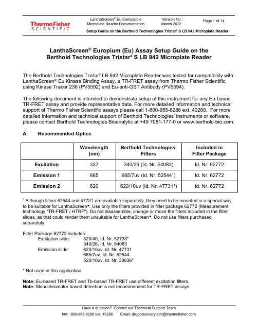
LanthaScreen® Europium (Eu) Assay Setup Guide on theBerthold Technologies Tristar² S LB 942 Microplate ReaderThe Berthold Technologies Tristar² LB 942 Microplate Reader was tested for compatibility with LanthaScreen® Eu Kinase Binding Assay, a TR-FRET assay from Thermo Fisher Scientific, using Kinase Tracer 236 (PV5592) and Eu-anti-GST Antibody (PV5594).The following document is intended to demonstrate setup of this instrument for any Eu-based TR-FRET assay and provide representative data. For more detailed information and technical support of Thermo Fisher Scientific assays please call 1-800-955-6288 ext. 40266. For more detailed information and technical support of Berthold Technologies’ instruments or software, please contact Berthold Technologies Bioanalytic at +49 7081-177-0 or .A. Recommended OpticsWavelength(nm) Berthold Technologies’FiltersIncluded inFilter PackageExcitation337 340/26 (Id. Nr. 54083) Id. Nr. 62772 Emission 1 665 665/7uv (Id. Nr. 525441) Id. Nr. 62772 Emission 2620 620/10uv (Id. Nr. 477311) Id. Nr. 627721Although filters 52544 and 47731 are available separately, they need to be mounted in a special way to be suitable for LanthaScreen®. Use only the filters provided in filter package 62772 (Measurement technology "TR-FRET / HTRF"). Do not disassemble, change or move the filters included in the filter slides, as that could render them unsuitable for LanthaScreen®. Do not use filters purchased separately.Filter Package 62772 includes:Excitation slide: 320/40, Id. Nr. 52733*340/26, Id. Nr. 54083Emission slide: 620/10uv, Id. Nr. 47731665/7uv, Id. Nr.52544520/10uv, Id. Nr. 38836** Not used in this application.Note: Eu-based TR-FRET and Tb-based TR-FRET use different excitation filters.Note: Monochromator based detection is not recommended for TR-FRET assays.IMPORTANT: The fluorescence module with extended spectral range is required to perform the LanthaScreen® Europium Assay in the Tristar² S.B. Instrument SetupThe following instructions are provided for the MikroWin software. The ICE software is also compatible with LanthaScreen®, and the same instrument settings can be easily programmed in ICE. Contact Berthold Technologies if you need support to program in ICE the instrument settings detailed here.1. Make sure the plate reader is turned on and then open the MikroWin software onthe computer.2. Click on Instrument >> Excitation Filter Slide. Check if the right filters areassigned to the right positions of the filter slides; if they are not, assign each filterto the corresponding position in the filter slide. Please follow the example below:Excitation slide xDSlot 1: 320/40 (HTRF Eu cryptate); usage: TRFluorescenceSlot 2: 340/26 (HTRF Tb cryptate); usage: TRFluorescence3. Click on Instrument >> Emission Filter Slide. Check if the right filters areassigned to the right positions of the filter slides; if they are not, assign each filter to the corresponding position in the filter slide (add new filters and enter thesettings below if needed). Please follow the example below:Emission Slide mDSlot 1: 620/10uv (HTRF Eu cryptate); usage: TRFluorescenceSlot 2: 665/7uv (HTRF XL665/APC); usage: TRFluorescenceSlot 3: 520/10uv; usage: TRFluorescence4. If you already have a pre-existing template for LanthaScreen®, open it and usethis document to review your settings; if you don’t have yet any suitable template, click on Settings in the menu bar at the top portion of the window to start creatinga new template.5. A new window will open. Select the Plate type corresponding to the plate you areusing and highlight the wells you most commonly will measure. If unsure aboutwhat plate type to select, contact Berthold Technologies for assistance.6. Click on the Measurement tab and look for the TRF operation.7. Double click on TRF to insert a TRF measurement operation. A new window willappear. If desired, enter a Name for the measurement operation. Configure the settings as shown in the screenshot below:•Enter Counting Time: 1.00•Select Aperture: 3 - Rd 2•Select Excitation Filter: 340/26 (HTRF Tb cryptate)*•Select Excitation Optic: 3 – Wide Filter 0.45mm•Select Emission Filter: 620/10uv (HTRF Eu cryptate)*•Enter Timing settings: Cycle Time 5000, Delay Time 100, Reading Time 300•Check Second Measurement•Select Excitation Filter: 340/26 HTRF Tb cryptate*•Select Emission Filter: 665/7uv (HTRF XL665/APC)*When finished, click OK.* The name of the filters in the software sometimes does not match the LanthaScreen® naming conventions, and sometimes filters named as “Tb cryptate” are mentioned in an Eu assay (or the other way around). This is not an error; filter naming was designed for HTRF® assays, but forLanthaScreen® different filter combinations are sometimes chosen for the best performance.8. To save the template, click on File in the main menu, then Template and Saveas. Browse to the desired folder, enter the desired filename and click OK.9. To start the measurement, enter the desired Plate ID to identify themeasurement. If you want to edit the wells to be measured, click on Settings and select the desired wells (see point 3). When you are ready, click Start. The plate tray will open; insert the plate and click OK to start the measurement.Test Your Plate Reader Set-up Before Using LanthaScreen® Eu Assays PurposeThis LanthaScreen® Eu Microplate Reader Test provides a method for verifying that a fluorescent plate reader is able to detect a change in time-resolved fluorescence energy transfer (TR-FRET) signal, confirming proper instrument set-up and a suitable response. The method is independent of any biological reaction or equilibrium and uses reagents that are on-hand for the LanthaScreen® assay.At a GlanceStep 1: This document can be found at /instrumentsetup.Step 2: Prepare individual dilutions of the TR-FRET acceptor (tracer, e.g. PV5592).2X = 1,600 nM, 800 nM, 400 nM, 200 nM and 50 nM.Note: To avoid propagating dilution errors, we do NOT recommend using serial dilutions. See page 10.Step 3: Prepare a dilution of the TR-FRET donor (Eu-Antibody, e.g. PV5594).2X = 125 nM Eu-chelate.Note: Concentration is based on the molarity of the Eu chelate (found on the Certificate of Analysis), NOT themolarity of the antibody, to account for normal variation in antibody labeling. See pages 11 - 12 forcalculations and method.Step 4: Prepare the plate and read.Step 5: Contact Technical Support with your results. E-mail us directly at ********************************** or in the US call 1-800-955-6288 ext. 40266. We will determine Z’-factors by comparing each concentration of acceptor to the200 nM acceptor data. Example results and data analysis are available on page 14.IntroductionThis LanthaScreen® Eu Microplate Reader Test uses diffusion-enhanced TR-FRET to generate a detectable TR-FRET signal. At high donor or acceptor concentrations, donor and acceptor diffuse to a suitable distance from one another to allow TR-FRET to occur, resulting in a signal. The response in diffusion-enhanced TR-FRET is easy to control because it is directly proportional to the concentrations of donor and acceptor in solution and is not related to a binding event.In this method, acceptor concentration varies while the donor concentration remains fixed. As the concentration of acceptor increases, the diffusion-enhanced TR-FRET signal increases. The signal from the acceptor concentrations are compared tothe signal from the lowest acceptor concentration to simulate assay windows from high to low allowing you to assess if your instrument is properly set-up and capable of detecting TR-FRET signals in the LanthaScreen® Assays.We designed the LanthaScreen® Eu technical note to use components and reagents that are generally used in the LanthaScreen® Eu Kinase Binding Assays. If you are using an Eu-based LanthaScreen® Activity or Adapta™ assay, call Technical Support for additional information.Materials RequiredComponent Storage Part Number Example ReagentsLanthaScreen® Eu-labeled antibody (donor) -20o C Various PV5594 LanthaScreen® Tracer (acceptor) -20o C Various PV55925X Kinase Buffer Room Temperature PV3189 PV3189*If you are using an Eu-based LanthaScreen® Activity or Adapta™ assay, call Technical Support for additional information.96-well polypropylene microplate or 1.5 mL microcentrifuge tubes384-well plate (typically a white, low-volume Corning 4513 or black, low-volume Corning 4514)Plate sealsSuitable single and multichannel pipettorsPlate reader capable of reading TR-FRETHandlingTo reread the plate on another day, seal and store the plate at room temperature for up to 5 days. To reread the plate, centrifuge the plate at 300 x g for 1 minute, remove seal and read.Important: Prior to use, centrifuge the antibody at approximately 10,000 x g for 5 minutes, and carefully pipette the volume needed for the assay from the supernatant. This centrifugation pellets aggregates present that can interfere with the signal. ProcedureStep 1: Set up your instrument using the information in this document.Step 2: Prepare the Acceptor (LanthaScreen® Kinase Tracer 236)Acceptor concentrations (2X) are individually prepared from a dilution of the Kinase Tracer stock (either 25 µM or 50 µM) to prevent propagation of error that can occur with serial dilutions. We suggest preparing 10 replicates for calculation of aZ’-factor. To accommodate replicates that use 10 µL per well, prepare 120 µL of each concentration. Prepare each concentration in micro-centrifuge tubes or a 96-well polypropylene plate and then transfer it to a 384-well plate.First prepare 1X Kinase Buffer A by adding 4 mL of 5X Kinase Buffer A to 16 mL of highly purified water. Diluted 1X Kinase Buffer A can be stored at room temperature.1.Prepare 2,500 nM acceptor stock solution:LanthaScreen® KinaseTracer Cat #Concentrationas SoldDilution to prepare a 2,500 nM solutionTracer 178 PV5593 25 µM Add 17 μL of tracer to 153 μL of 1X Kinase Buffer A Tracer 199 PV5830 25 µM Add 17 μL of tracer to 153 μL of 1X Kinase Buffer A Tracer 236 PV5592 50 µM Add 8.5 μL of tracer to 161.5 μL of 1X Kinase Buffer A Tracer 314PV6087 25 µM Add 17 μL of tracer to 153 μL of 1X Kinase Buffer A Tracer 1710PV6088 25 µM Add 17 μL of tracer to 153 μL of 1X Kinase Buffer A2. Prepare 120 μL of each 2X acceptor concentration from the 2,500 nM stock:96-well plate or tubes A1B1C1D1E1 2X Acceptor Concentration1,600 nM 800 nM 400 nM 200 nM 50 nM Final 1X Acceptor Concentration800 nM 400 nM 200 nM 100 nM 25 nM Volume 1X Kinase Buffer A43 μL 81.6 μL 100.8 μL 110.4 μL 117.6 μLVolume 2,500 nM Acceptor(prepared above)77 μL 38.4 μL 19.2 μL 9.6 μL 2.4 μLStep 3: Prepare the Donor (Eu-Chelate Labeled Antibody)Prepare a 2X stock of Eu-chelate at 125 nM that will result in a final assay concentration of 62.5 nM. This method relies on the concentration of Eu-chelate, NOT the concentration of antibody. The lot-to-lot variation in the number of Eu-chelates covalently bound to antibody can be accounted for by referring to the Eu-chelate-to-antibody ratio listed on the lot-specific Certificate of Analysis for your antibody. Multiply this ratio by the antibody concentration to calculate the Eu-chelate concentration.Example chelate concentrationsAntibody Concentration Antibody Molarity Chelate: Antibody Ratio Chelate Concentration0.5 mg/mL 3.3 μM 11 36.3 μM = 36,300 nM0.25 mg/mL 1.7 μM 8 13.6 μM = 13,600 nMExample Calculation: Prepare 1,000 μL of Eu-chelate:Eu-antibody = 0.5 mg/mL (3.3 μM) with a chelate:antibody ratio of 11Chelate: Stock = 3.3 μM x 11 = 36.3 μM = 36,300 nM.1X = 62.5 nM; 2X = 125 nMFormula V1 X C1 = V2X C2[Stock] [2X]Eu-Chelate V1 X 36,300 nM = 1,000 μL X 125 nM V1 = 3.4 μLAdd 3.4 μL of 36,300 nM stock to 996.6 μL 1X Kinase Buffer A.Step 4: Add Reagents to the 384-well plate and read1.DonorTransfer 10 μL of 2X Eu-chelate to rows A through J and columns 1 through 5 of the 384-well assay plate. Since you need only a single concentration, you can transfer this solution with a multichannel pipettor from a basin to all 50 wells. We recommend preparing the 1 mL solution in a 1.5 mL micro-centrifuge tube before transferring into the basin.2.AcceptorNote:To eliminate carryover, we recommend changing pipette tips for each concentration of acceptor.Note:After adding 2X acceptor, mix the reagents by pipetting up and down.Transfer 10 μL of the indicated concentration of 2X acceptor to the rows A-J of the corresponding column of the 384- well plate.2X Acceptor Column1,600 nM 1800 nM 2400 nM 3200 nM 450 nM 53. Read the plateThis step does not require any equilibration time.Step 5: Contact Technical SupportSend us your results by e-mailing us directly at ********************************** or in the US call 1-800-955-6288 ext.40266.We will help you evaluate your results by performing the following data analysis:Ratiometric data obtained on a Berthold Technologies Tristar² S LB 942 microplate reader.[Acceptor]800 nM 400 nM 200 nM 100 nM 25 nM Row A0.037 0.025 0.017 0.012 0.008 Row B0.036 0.026 0.018 0.012 0.008 Row C0.034 0.025 0.017 0.012 0.008 Row D0.033 0.024 0.017 0.012 0.008 Row E0.036 0.025 0.017 0.012 0.007 Row F0.036 0.023 0.017 0.012 0.008 Row G0.032 0.026 0.017 0.012 0.008 Row H0.033 0.021 0.016 0.012 0.008 Row I0.032 0.024 0.017 0.012 0.008 Row J0.032 0.023 0.018 0.012 0.008Data Analysis:[Acceptor]800 nM400 nM200 nM100 nM25 nM Average Ratio0.0340.0240.0170.0120.008 St dev0.00200.00130.00060.00020.0003 % CV 5.82 5.36 3.58 2.04 3.42 Assay4.31 3.05 2.15 1.52ReferenceWindowZ’-factor0.740.710.710.63For Research Use Only. Not intended for any animal or human therapeutic or diagnostic use.。
JBC-Tools_CLMU-A8_clmu-a8-lead-free-soldering-meta

CLUP7 / CLUP8 Non-Metal* / Non-Metal HMP* Gentle
5s
1-2 s
1-2 s
Extended* Black
Extended* Blue
*Only use the non-metal brushes when they are rotating. Incorrect use will damage them.
For CLU pull the locking tab to open the splashguard.
CLR Splashguard
Press the brush buttons (1) to remove the brushes (2).
1
CLU
Align the brush with the axis and push them in until a click is heard. Check if the brush is properly fixed.
0021174-0222
130 mm
INSTRUCTION MANUAL
CLU7 / CLU8 CLUP1 / CLUP2 CLUP7 / CLUP8
Metal and Non-Metal Brushes for CLU & CLR
This manual corresponds to the following references:
CLMU-A7* CLMU-A8* *each ref. incl. 2 brushes
CLMU-P1* CLMU-P2*
Packing List
The following items should be included:
PCR targeting system in Streptomyces coeliclor A3(2)
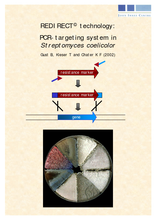
REDIRECT ©technology:PCR-targeting system in Streptomyces coelicolorGust B, Kieser T and Chater K F (2002)PCR targeting system in Streptomyces coelicolor A3(2)Bertolt Gust, Tobias Kieser and Keith Chater, John Innes Centre, Norwich Research Park, Colney, Norwich NR47UH, UK, Tel: +44 (0)1603 452751 Fax: +44 (0)1603 456844IntroductionMany bacteria are not readily transformable with linear DNA because of the presenceof the intracellular recBCD exonuclease that degrades linear DNA. However, the λ RED (gam, bet, exo) functions promote a greatly enhanced rate of recombination when using linear DNA. By exploiting this, Datsenko and Wanner (2000) made 40 different disruptions on the E. coli chromosome by replacing the wild-type sequences with a selectable marker generated by PCR using primers with 36 nt homology extensions.The strategy for PCR-targeting for mutagenesis of Streptomyces coelicolor is to replace a chromosomal sequence within a S. coelicolor cosmid (Redenbach et al., 1996) by a selectable marker that has been generated by PCR using primers with 39 nt homology extensions. The inclusion of oriT (RK2) in the disruption cassette allows conjugation to be used to introduce the PCR targeted cosmid DNA into S. coelicolor. Conjugation is much more efficient than transformation of protoplasts and it is readily applicable to many actinomycetes (Matsushima et al., 1994). The potent methyl-specific restriction system of S. coelicolor is circumvented by passaging DNA through a methylation-deficient E. coli host such as ET12567 (MacNeil et al., 1992). Vectors containing oriT (RK2; Pansegrau et al., 1994) are mobilisable in trans in E. coli by the self-transmissible pUB307 (Bennett et al., 1977, Flett et al., 1997) or the non-transmissible pUZ8002, which lacks a cis-acting function for its own transfer (Kieser et al., 2000).To adapt the procedure of λ RED mediated recombination for Streptomyces, cassettes for gene disruptions were constructed that can be selected both in E. coli and in Streptomyces (Table 1). After a single disruption with an oriT-containing cassette, further disruptions can be performed on the same cosmid using oriT-free cassettes containing alternative selective markers. The λ RED recombination plasmid pKD20(E. coli Genetic Stock Center CGSC Strain # 7637) was modified by replacing the ampicillin resistance gene bla with the chloramphenicol resistance gene cat, generating pIJ790, to permit selection in the presence of Supercos1-derived cosmids (ampicillin and kanamycin resistance).Name of plasmid Resistance-markerResistanceConcentrationfor E. colioriT Size of templatepIJ773 Fig. 5 aac(3)IV apramycin50 µg/ml LB + 1382bppIJ778 Fig. 6 aadAspectinomycinstreptomycin50 µg/ml LB50 µg/m LB+ 1425bppIJ779. aadA spectinomycin-streptomycin50 µg/ml LB50 µg/ml LB- 1057bppIJ780 Fig.7 vph viomycin30 µg/ml DNA + 1497bppIJ781 vph viomycin30 µg/ml DNA - 1622bpTable 1: Disruption cassettes containing different resistance markers with and without oriT: All disruption cassettes were cloned into the Eco RV site of pBluescript SK II (+) allowing the isolation of a Eco RI/Hind III fragment for use as template for the PCR reaction. The size of the cassettes includes the 19 bp and 20 bp primer site (see section 2: “primer design”) which are identical in all disruption cassettes. The resistance genes with or without oriT are flanked by FRT sites (FLP recognition targets) which allows FLP-mediated excision of the cassette (see section 7: “FLP-mediated excision of the disruption cassette”).Fig. 1: Flowchart of gene disruption by PCR-targetingProtocol (see Flowchart Fig. 1)Using whole plasmids as templates for the PCR can result in a high proportion of antibiotic-resistant transformants without gene disruption. This is caused by traces of CCC DNA that compete with the linear PCR fragment and result in the occurrence of false positive transformants. Using gel-purified disruption cassettes as templates prevents the occurrence of false positives.1. Digest ~ 10 µg plasmid DNA (see Table 1) with 50 U Eco RI (Roche) and50 U Hin dIII (Roche) in 1 X buffer B (Roche) in a 100 µl reaction.• A 2938 bp vector fragment and a fragment 14 bp larger than the size of the cassette given in Table 1 should be generated.2. Run the digest on a 20 x 20 x 0.25 cm (100 ml) 1% TAE (1x) agarose gel at5V/cm for 2 - 3 h in 1x TAE buffer.• Longer runs exhaust the buffer capacity and destroy the gel unless the buffer is recycled.3. Cut out the cassette band from the gel and purify using the Qiagen gelextraction kit. The purified fragment is stored in 10 mM Tris.HCl (pH 8) at aconcentration of 100 ng / µl at –20°C.4. Absence of plasmid DNA is tested by using 1µl (100 ng) of purified cassetteDNA to transform highly competent E. coli DH5α cells (108/µg). Plate on LBagar containing 100 µg/ml carbenicillin. If any transformants appear, repeatsteps 2-4.Design of long PCR primersFor each gene disruption, two long PCR primers (58 nt and 59 nt) are required. Each has at the 5´end 39 nt matching the S. coelicolor sequence adjacent to the gene to be inactivated, and a 3´sequence (19 nt or 20 nt) matching the right or left end of the disruption cassette (all cassettes have the same “right” and “left” ends). The precise positioning of the 39 nt sequence as indicated in Fig. 2 is important for creating in-frame deletions by FLP recombinase-induced excision of the resistance marker (see section 7).•The 5´- 39 nt sequence of the forward primer (upstream primer; Fig. 2) must be from the coding strand of the gene of interest and its 3’ end must be in the correct reading frame with respect to the replaced gene. The 5´- 39 nt sequence of the reverse primer (downstream primer; Fig. 2) must be from the complementary strand. •To prevent unwanted recombination, a BlastN search is performed comparing each 39 nt sequence with the “real cosmid” (sequences at the Sanger Centre Homepage in the folder /S_coelicolor/cosmid inserts). The perfect match should be found but no other matches >30 bp. If necessary, the 39 nt sequence is shifted in 3 nt steps until the above criteria are met.6(20bp + 19bp priming sequence + 42bp FLP core recombination site (see Fig.3); no in frame STOP)Fig.2: Designing PCR primers for making an in-frame deletion(the example illustrates a complete deletion)39 nt from sense strand ending in ATG or GTG start codon39 nt from anti-sense strand ending in Stop codon58 nt downstream primerFLP recombinase (BT340)PCR amplification of the extended resistance cassetteAll PCR amplifications are performed using the Expand high fidelity PCR system according to the manufacturer’s instructions (Roche). Reaction conditions: • Primers (100 pmoles/µl) 0.5 µl each 50 pmoles each • Template DNA (100 ng/µl) 0.5 µl 50 ng ≈ 0.06 pmoles • Buffer (10x) 5 µl 1 x • dNTPs (10 mM) 1 µl each 50 µM each • DMSO (100 %) 2.5 µl 5% • DNA polymerase (2.5 U/µl) 1 µl 2.5 Units • Water 36 µl •Total volume 50 µlCycle conditions:1. Denaturation:94°C, 2 min 2. Denaturation: 94°C, 45 sec3. Primer annealing: 50°C , 45 sec 10 cycles4. Extension: 72°C, 90 sec5. Denaturation: 94°C, 45 sec6. Primer annealing: 55°C , 45 sec 15 cycles7. Extension: 72°C, 90 sec8. Final extension: 72°C, 5 min5 µl of the PCR product is used for analysis by gel electrophoresis. The expected sizes are 78 bp larger than the sizes of the disruption cassettes listed in Table 1 (because of the 2 x 39 bp 5´-primer extensions). The remaining 45 µl of the PCR product is purified using the Qiagen PCR purification kit according to the manufacturer’s instructions. The PCR product is finally eluted from the columns with 12 µl of water (~200 ng/µl).(λ RED recombination plasmid) by electroporationpIJ790 contains the resistance marker cat (chloramphenicol resistance) and a temperature sensitive origin of replication (requires 30°C for replication).1. Grow E. coli BW25113/pIJ790 overnight at 30°C in 10 ml LB (Luria-Bertanimedium; Sambrook et al., 1998) containing chloramphenicol (25 µg/ml).2. Inoculate 100 µl E. coli BW25113/pIJ790 from overnight culture in 10 mlSOB (Hanahan, 1983) containing 20 mM MgSO4 (add 200 µl of 1M stock to10 ml SOB) and chloramphenicol (25 µg/ml).3. Grow for 3-4 h at 30°C shaking at 200 rpm to an OD600 of ~ 0.4.4. Recover the cells by centrifugation at 4000 rpm for 5 min at 4°C in a SorvallGS3 rotor (or equivalent).5. Decant medium and resuspend the pellet by gentle mixing in 10 ml ice-cold10 % glycerol.6. Centrifuge as above and resuspend pellet in 5 ml ice-cold 10 % glycerol,centrifuge and decant. Resuspend the cell pellet in the remaining ~ 100 µl10 % glycerol.7. Mix 50 µl cell suspension with ~ 100 ng (1-2 µl) of cosmid DNA. Carry outelectroporation in a 0.2 cm ice-cold electroporation cuvette using a BioRad GenePulser II set to: 200 Ω, 25 µF and 2,5 kV. The expected time constant is4.5 – 4.9 ms.8. Immediately add 1 ml ice cold LB to shocked cells and incubate shaking for1h at 30°C.9. Spread onto LB agar containing carbenicillin (100 µg/ml), kanamycin(50 µg/ml) and chloramphenicol (25 µg/ml).10. Incubate overnight at 30°C.11. Transfer one isolated colony into 5 ml LB containing antibiotics as in (9)above.12. Incubate overnight at 30°C. This culture will be used as a pre-culture forgenerating competent cells to be transformed with the extended resistancecassette.PCR targeting of the S. coelicolor cosmidE. coli BW25113/pIJ790 containing a S. coelicolor cosmid is electro-transformed with the extended resistance cassette. The example described uses the apramycin – oriT disruption cassette from pIJ773. Table 1 lists alternative cassettes and their resistance determinants.1. Inoculate a 10 ml SOB – MgSO4 culture containing carbenicillin (100 µg/ml),kanamycin (50 µg/ml) and chloramphenicol (25 µg/ml) with 1% of the overnight culture of E. coli BW25113/pIJ790 and the S. coelicolor cosmid.Add 100 µl 1M L-arabinose stock solution (final concentration is 10 mM, induces red genes).2. Grow for 3-4 h at 30°C shaking at 200 rpm to an OD600 of ~ 0.4.3. Recover the cells by centrifugation at 4000 rpm for 5 min at 4°C in a SorvallGS3 rotor (or equivalent).4. Decant medium and resuspend the pellet by gentle mixing in 10 ml ice-cold10% glycerol.5. Centrifuge as above and resuspend pellet in 5 ml ice-cold 10 % glycerol,centrifuge and decant. Resuspend the cell pellet in remaining ~ 100 µl 10 % glycerol.6. Mix 50 µl cell suspension with ~ 100 ng (1-2 µl) of PCR product. Carry outelectroporation in a 0.2 cm ice-cold electroporation cuvette using a BioRad GenePulser II set to: 200 Ω, 25 µF and 2,5 kV. The expected time constant is4.5 – 4.9 ms.7. Immediately add 1 ml ice cold LB to shocked cells and incubated shaking 1 hat 37°C (or 30°C if further gene disruptions will be made on the same cosmid;see below).8. Spread onto LB agar containing carbenicillin (100 µg/ml), kanamycin(50 µg/ml) and apramycin (50 µg/ml). If no further gene disruptions will bemade on this cosmid, incubate overnight at 37°C to promote the loss of pIJ790. (If further disruptions are planned propagate overnight at 30°C and include chloramphenicol (25 µg/ml) so that pIJ790 is retained).• If no colonies are obtained after 16 h growth at 37°C, repeat the experiment starting with a 50 ml SOB culture instead of 10 ml culture for generatingelectrocompetent cells. Try to concentrate the cells as much as possible byremoving all of the remaining 10% glycerol. Resuspend the cell pellet in 50 µl10% glycerol and use for electroporation.• After 12 – 16 h growth at 37°C different colony-sizes are observed. Cultivating for longer time results in an increased background of small colonies, which arefalse positives. It is important to note that at this stage wild-type and mutantcosmids exist within one cell. The transformation with a PCR product and itsintegration in the cosmid DNA by homologous recombination will not occur inall copies of the cosmid molecules in one cell. One copy of a cosmid containingthe incoming resistance marker is sufficient for resistance to this antibiotic.Normally, the larger the size of a colony, the more copies of mutagenisedcosmids are present. Inoculating a large colony in 5 ml LB liquid culturescontaining carbenicillin (100 µg/ml), kanamycin (50 µg/ml) and apramycin(50 µg/ml) result in a growth at 37°C to a cell density (OD600 ~ 0.1 – 0.3) within3-4 h (E. coli BW25113 without pIJ790 grows very fast). After 6 h plasmid DNAcan be isolated and tested by restriction analysis and/or PCR using the primersdescribed below.• PCR analysis with a primer pair (test primers) priming just ~ 100 bp outside the region affected by homologous recombination will generate the expectedfragment after gene disruption, but will usually also generate the wild-typefragment, caused by remaining wild-type copies within the same transformant.These will be lost during the subsequent transformation step into themethylation-deficient E. coli host ET12567 containing the non-transmissibleplasmid pUZ8002 (this is not a problem anyway because wild-type copies lackthe oriT).• Notes on viomycin selection: selecting for viomycin R depends critically on the amount of salt in the medium; more viomycin is required at higher saltconcentrations. For a clean selection of E. coli clones, use DNA agar or 2xYTagar containing 30 µg/ml viomycin (see Kieser et al., 2000).For multiple gene replacements, choose an oriT-containing disruption cassette for the first knock-out, and a cassette without oriT and different resistance markers for further gene disruptions.The gene disruption is confirmed by restriction analysis and/or PCR. Cosmid DNA of transformants is isolated from a 6 h, 37°C, 5 ml LB culture containing carbenicillin (100 µg/ml), kanamycin (50 µg/ml) and apramycin (50 µg/ml). Alkaline lysis followed by phenol/chloroform extraction produces cosmid DNA suitable for restriction analysis.Cosmid CCC DNA isolation1. Resuspend the cell pellet from 1 ml culture by vortexing in 100 µl solution I(50 mM Tris/HCl, pH 8; 10 mM EDTA).2. Immediately add 200 µl solution II (200 mM NaOH; 1% SDS) and mix byinverting the tubes 10x.3. Immediately add 150 µl solution III (3 M potassium acetate, pH 5.5) and mixby inverting the tubes 5x.4. Spin at full speed in a microcentrifuge for 5 min at room temperature.5. Immediately extract supernatant with 400 µl phenol/chloroform, vortex 2 minand spin at full speed in a micro centrifuge for 5 min.6. Transfer the upper phase and add 600 µl 2-propanol. Leave the tubes on icefor 10 min.7. Spin as above and wash the pellet with 200 µl 70% ethanol.8. Spin as above and leave the tube open for 5 min at room temperature to drythe pellet. Resuspend the pellet in 50 µl 10mM Tris/HCl (pH 8) and use 10 µl for restriction digest.• Omitting the phenol/chloroform extraction step results in degradation of the cosmid DNA. Use of miniprep-columns without including a phenol/chloroformextraction is not recommended.Verification of positive transformants by PCR requires an additional pair of 18 – 20 nt test primers which anneal 100 – 200 bp upstream and downstream of the 39 bp recombination region. (These primers can also be used later to verify the FLP-mediated excision of the resistance cassette.)• Primers (100 pmoles/µl) 0.2 µl each 20 pmoles each• Template DNA (~50 ng/µl) 1 µl 50 ng1µlx• Buffer5(10x)• dNTPs (10 mM) 1 µl each 50 µM each• DMSO (100 %) 2.5 µl 5%• DNA polymerase (2.5 U/µl) 1 µl 2.5 Units• Waterµl36.150µlvolume• TotalCycle conditions:1. Denaturation: 94°C, 2 min2. Denaturation: 94°C, 45 sec3. Primer annealing: 55°C, 45 sec 30 cycles4. Extension: 72°C, 90 sec5. Final extension: 72°C, 5 min5 µl of the PCR product is used for gel electrophoresis.Transfer of the mutant cosmids into StreptomycesIf the target Streptomyces for mutagenesis carries a methyl-sensing restriction system (as is the case for S. coelicolor and S. avermitilis), it is necessary to passage the cosmid containing an apramycin resistance-oriT cassette through a non-methylating E. coli host. To achieve this, it is introduced by transformation into the non-methylating E. coli ET12567 containing the RP4 derivative pUZ8002. The cosmid is then transferred to Streptomyces by intergeneric conjugation (see Table 2 for resistance markers). If the target Streptomyces for mutagenesis does not carry a methyl-sensing restriction system (as is the case for S. lividans), common E. coli strains such as DH5α containing pUZ8002 can be used instead.Description Name Replication Carb R Cml R Kan R Tet RS. coelicolorSupercos 1 Carb R Kan Rcosmid clonesλ Red plasmid pIJ790 t s Cml RFLP recombinaseBT340 t s Carb R Cml RplasmidOriT- RP4 derivative pUZ8002 Kan ROriT+ RP4 derivative pUB307 Kan RNon-methylating E. coli ET12567 Cml R Tet RTable 2. Resistance markers of vectors, helper plasmids and strains (carbenicillin resistance (Carb R ), chloramphenicol resistance (Cml R), kanamycin resistance (Kan R), tetracycline resistance (Tet R), temperature sensitive replicon (t S)). See Table 1 for replacement cassettes.1. Prepare competent cells of E. coli ET12567/pUZ8002 grown at 37ºC in LBcontaining kanamycin (25 µg/ml) and chloramphenicol (25 µg/ml) to maintain selection for pUZ8002 and the dam mutation, respectively. (ET12567 has a doubling time > 30 min.)• High competence is required when Dam-methylated plasmids are introduced into a dam- strain.2. Transform competent cells with the oriT-containing cosmid clone, and selectfor the incoming plasmid only using apramycin (50 µg/ml) and carbenicillin (100 µg/ml) .3. Inoculate a colony into 10 ml LB containing apramycin (50 µg/ml),chloramphenicol (25 µg/ml) and kanamycin (50 µg/ml). Grow overnight at37ºC.• Chloramphenicol S or Kanamycin S segregants arise frequently among transformants, so set up more than one culture. The kanamycin selection is probably ineffectivebecause both the cosmid and pUZ8002 confer resistance (Table 2).4. Inoculate 100 µl overnight culture into 10 ml fresh LB plus antibiotics asabove and grow for ~ 4 h at 37°C to an OD600 of 0.4.5. Wash the cells twice with 10 ml of LB to remove antibiotics that might inhibitStreptomyce s, and resuspend in 1 ml of LB.6. While washing the E. coli cells, for each conjugation add 10 µl (108)Streptomyces spores to 500 µl 2 × YT broth. Heat shock at 50°C for 10 min,then allow to cool.7. Mix 0.5 ml E. coli cell suspension and 0.5 ml heat-shocked spores and spinbriefly. Pour off most of the supernatant, then resuspend the pellet in thec. 50 µl residual liquid.8. Make a dilution series from 10-1 to 10-4 each step in a total of 100 µl of water.9. Plate out 100 µl of each dilution on MS agar + 10mM MgCl2 (withoutantibiotics) and incubate at 30°C for 16-20 h.10. Overlay the plate with 1 ml water containing 0.5 mg nalidixic acid (20 µl of25 mg/ml stock; selectively kills E. coli) and 1.25 mg apramycin (25 µl of50 mg/ml stock). Use a spreader to lightly distribute the antibiotic solutionevenly. Continue incubation at 30°C.11. Replica-plate each MS agar plate with single colonies onto DNA platescontaining nalidixic acid (25 µg/ml) and apramycin (50 µg/ml) with andwithout kanamycin (50 µg/ml). Double cross-over exconjugants are kanamycin S and apramycin R. (DNA gives fast, non-sporulating growth.)12. Kanamycin S clones are picked from the DNA plates and streaked for singlecolonies on MS agar (promotes sporulation) containing nalidixic acid(25 µg/ml) and apramycin (50 µg/ml).13. Confirm kanamycin sensitivity by replica-plating onto DNA plates containingnalidixic acid (25 µg/ml) with and without kanamycin (50 µg/ml).14. Purified kanamycin sensitive strains are then verified by PCR and Southernblot analysis.• Typically, ~ 10 % of the exconjugants are double cross-over recombinants. Thefrequency of double cross-overs depends on the length of the flanking regions ofhomologous DNA on the cosmid. If < 1 kb is left on one side of the disrupted gene,obtaining kanamycin S double cross-over types directly on the conjugation plates maybe difficult. It may be necessary to streak out several exconjugants for single colonieson MS agar without antibiotics. After 3-5 days growth replica-plate onto DNA withand without kanamycin.Concentration in Antibiotic Stockmg/ml µl for 1 mloverlay Final conc. after flooding µg/ml MS, DNA µg/ml R2YE µg/mlApramycin 50 25 50 50 50 Kanamycin 50 100 200 50 200 Spectinomycin 200 25 200 400 400 Streptomcyin 10 25 10 10 10 Viomycin 30 25 30 30 NANalidixic acid25 in0.3 M NaOH 20 20 25 25Table 3: Antibiotic concentrations for selection on S. coelicolor MS conjugation plates, DNA replicaplates or R2YE protoplast regeneration plates (Note some small differences from Kieser et al ., 2000).FLP-mediated excision of the disruption cassetteThe disruption cassettes are flanked by FRT sites (FLP recognition targets). Expression of the FLP-recombinase inE. coli removes the central part of thedisruption cassette, leaving behind a 81 bp “scar” sequence which, in the preferred reading frame (bold in Fig. 3), lacks stop codons.Fig. 3: Sequence of the 81 bp “scar” sequence remaining after FLP-mediated excision of the disruption cassette. The translation of the preferred reading frame is printed bold. The 20 and 19 nt priming sites are underlined and printed in colour. (Fig. 2 explains the determination of the reading frame.) indicate stop codons,priming site (20 nt) priming site (19 nt)This allows the generation of (hopefully) non-polar, unmarked in-frame deletions and repeated use of the same resistance marker for making multiple knock-outs in the same cosmid or in the same strain. E. coli DH5α cells containing the temperature sensitive FLP recombination plasmid BT340 (Datsenko and Wanner, 2000; can be obtained from the E. coli Genetic Stock Center: CGSC Strain# 7629) are transformed with the mutagenised cosmid DNA (obtained in section 5). BT340 contains ampicillin and chloramphenicol resistance determinants and is temperature sensitive for replication (replicates at 30°C). FLP synthesis and loss of the plasmid are induced at 42°C (Cherepanov and Wackernagel, 1995).1. Grow E. coli DH5α/BT340 overnight at 30°C in 10 ml LB containingchloramphenicol (25 µg/ml).• Transforming E. coli BW25113/cosmid::apramycin (mutagenised cosmid) with the plasmid BT340 is not recommended because the isolates after PCR targetingmay still contain copies of undisrupted cosmid DNA (see page 10, secondparagraph).2. Inoculate 100 µl E. coli DH5α/BT340 from overnight culture into 10 mlLB containing chloramphenicol (25 µg/ml).3. Grow for 3-4 h at 30°C shaking at 200 rpm to an OD600 of ~ 0.4.4. Recover the cells by centrifugation at 4000 rpm for 5 min at 4°C in aSorvall GS3 rotor (or equivalent).5. Decant medium and resuspend the pellet by gentle mixing in 10 ml ice-cold 10 % glycerol.6. Centrifuge as above and resuspend pellet in 5 ml ice-cold 10 % glycerol,centrifuge and decant. Resuspend the cell pellet in remaining ~ 100 µl 10% glycerol.7. Mix 50 µl cell suspension with ~ 100 ng (1-2 µl) of mutagenised cosmidDNA. Carry out electroporation in a 0.2 cm ice-cold electroporation cuvette using a BioRad GenePulser II set to: 200 Ω, 25 µF and 2,5 kV. The expected time constant is 4.5 – 4.9 ms.8. Immediately add 1 ml ice cold LB to shocked cells and incubate shakingfor 1 h at 30°C.9. Spread onto LB agar containing apramycin (50 µg/ml) andchloramphenicol (25 µg/ml).10. Incubate for 2 d at 30°C (E. coli DH5α/BT340 grows slowly at 30°C).11. A single colony is streaked on an LB agar plate without antibiotics forsingle colonies and grown overnight at 42°C to induce expression of the FLP recombinase followed by the loss of plasmid BT340.12. Make two masterplates by streaking 20 – 30 single colonies with atoothpick first on a LB agar plate containing apramycin (50 µg/ml) and then on a LB agar plate containing kanamycin (50 µg/ml).13. Grow the masterplates overnight at 37°C. Apramycin S kanamycin R clonesindicate the successful loss of the resistance cassette and are furtherverified by restriction and PCR analysis.• Typically, ~ 10 % of the single colonies after non-selective growth lose the incoming resistance marker and the plasmid BT340 simultaneously.• Using the same test primers as in section 5 (annealing ~ 100 bp upstream and downstream of the 39 nt primer sequence) should produce a PCR product of~ 300 bp (200 bp + 81 bp “scar”). PCR fragments can be sequenced using theamplification primers for verification.Replacing resistance cassette inserts in S. coelicolor with the unmarked “scar” sequenceThe chromosomal apramycin resistance cassette insert in S. coelicolor is replaced by the “scar” sequence. This is achieved by homologous recombination between the chromosome and the corresponding “scar cosmid” prepared in 7. The procedure differs from section 6 because the cosmid lacks oriT, and the desired product is antibiotic sensitive. Therefore, it is necessary to introduce the scar cosmid into Streptomyces by protoplast transformation, and then select for kanamycin resistant Streptomyces containing the entire scar cosmid integrated by a single crossover. Restreaking to kanamycin-free medium, followed by screening for concomitant loss of kanamycin resistance and apramycin resistance, then identifies the desired Streptomyces clones.Preparation of Streptomyces coelicolor protoplasts1. Add 25 ml YEME medium to a baffled flask. Add ~ 0.1 ml spore suspensionand required growth factors. Incubate 36-40 h at 30°C in an orbital incubator shaker.• Cultures of S. lividans and S. coelicolor are ready for harvesting when they start to produce red pigment2. Pour culture broth into a 20 ml screw cap bottle and spin in the benchcentrifuge (~ 1000 x g, 10 min).• Before centrifugation, examine the culture for contamination by unicellular bacteria, usually indicated by turbidity: the Streptomyces mycelium sedimentsquickly while unicellular contaminants remain suspended. In case of doubt, use the microscope.3. Discard the supernatant carefully; the pellet is easily disturbed.• If the mycelium does not pellet add 5 ml sterile water to reduce the density of the medium and centrifuge again.4. Resuspend pellet in 15 ml 10.3% sucrose and spin in bench centrifuge asabove. Discard supernatant.5. Repeat step 4.• The mycelial pellet, without added liquid, can be stored frozen at –20°C6. Resuspend mycelium in 4 ml lysozyme solution (1 mg/ml P buffer, filtersterilised); incubate at 30°C, 15-60 min.7. Draw in and out of a 5 ml pipette three times and incubate for a further 15min.• This helps to free protoplasts from the mycelium so that they will pass through the cotton wool filter used in step9. At least with S. lividans, it is possible to obtain transformants with unfiltered material, but the washing (steps 9-10) is still needed to remove lysozyme.8. Add 5 m1 P buffer. Repeat step 7.9. Filter protoplasts through cotton wool (using a filter tube) and transfer to aplastic tube.10. Sediment protoplasts gently by spinning in a bench centrifuge (~ 1000 x g, 7min).11. Discard supernatant and suspend protoplasts in 1 ml P buffer.• At this and any other steps when pelleted protoplasts are to be resuspended, resuspend in the remaining drop of liquid by tapping the side of the tube repeatedly with a finger until the protoplasts are dispersed to form a creamy suspension, then add the suspending P buffer (otherwise the protoplast pellet is difficult to disperse).Avoid vortexing, which induces foaming and consequent lysis. To freeze the protoplasts for storage, place samples of the protoplast suspension in small plastic tubes, close them and place them in ice in a plastic beaker. Place the beaker at –70°C overnight. Free the frozen protoplasts in their tubes from the ice and store at –70°C.To thaw, shake the frozen tube under running warm water (i.e. freeze slowly, thaw quickly). To assess the proportion of non-protoplasted units in the suspension, samples can be diluted in parallel in P buffer and in dilute detergent (~ 0.01% SDS) and plated on regeneration plates. Any colonies arising after dilution in detergent are likely to have arisen from non-protoplasted units.。
液晶弹性体

3. Actuators based on LCEs
3.1. Actuators based on thermally actuated LCEs
Fig 3. Micrometer-sized nematic LCE actuators consisting of a pillar array. (a) Experimental setup used to prepare the responsive pillars. (b) Top view (under an optical microscope) of the pillar pattern obtained by the imprint in the nematic liquid crystal elastomer. (Inset) Zoom on the structure (pillar diameter=20mm)[1]. [1 ]Buguin A, Li M H, Silberzan P, et al. Journal of the American Chemical Society, 2006, 128(4): 1088-1089.
4. Summary
1.Introduction
Smart materials:
There is a group of materials capable of responding to external stimuli with mechanical deformation.
Fig 1. The diferent kinds of actuator materials both in natural and synthetic systems
3. Actuators based on LCEs
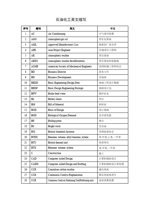
石油化工英文缩写
15
BOD
Basis of Design
设计基础
16
BOD
Biological Oxygen Demand
化学需氧量
17
BP
Boiling point
沸点
18
BS
Bright stock
光亮油
19
BSI
British Standards Institute
英国标准协会
20
BTEX
Benzene, toluene, ethyl benzene, xylene
计算机辅助设计和绘图
26
CCR
Conradson carbon residue
康氏残炭
27
CCR
Continuous Catalyst Regeneration
催化剂连续再生
28
CCR
Continuous Catalystic Reforming Unit(Platforming unit)
连续重整装置
芳烃抽提
44
FEED
Front End Engineering Design
前期工程设计
45
GB
GUO BIAO
国标
46
GCD
Guaranteed Completion Date
保证完成日期
47
GEU
Gasoline Etherization Unit
汽油醚化装置
48
GG
Gauge glass
玻璃液面计
MRR
Material Receiving Report
材料验收单
134
MTO
Material Take-Off
orca_settings_3.0.1_v1.0
ORCA v3.0.1Simple Keywords ReferenceRevision 1.0Brian T.Skinnbskinn@March 31,20141IntroductionCertain simple keywords in ORCA change tolerances,thresholds,etc.,that are otherwise either set (a)by de-fault or (b)by the user through the input block of each program within the ORCA suite.For clarity of nomenclature,a sample ORCA input fragment is providedin the inset figure.The first line uses the simple input syntax,and requests a restricted DFT geometry optimization using the def2-TZVP Ahlrichs basis set and the B3LYP functional,with a following numerical frequencycalculation.The simple keywords GRID4,TIGHTSCF ,and TIGHTOPT supplied in the second line effect multiple changes to the behavior of ORCA,relating to DFT grid refinement,SCF convergence tolerances,and geometry optimizationparameters,respectively.The fourth through sixth lines are provided as an example of the block input syntax,in this case the %freq block,which controls the Hessian calculation for vibrational frequencies and thermochemistry.The %freq.Increment keyword specified in the example controls the magnitude of the atomic displacements in the numerical Hessian calculation.This document aims to be a quick reference for the detailed effects of simple input keywords like those of the second line,which alter multiple ORCA settings.The information provided herein is based upon the ORCA v3.0.1input parser C ++code,kindly provided by Dr.Frank Neese on 29Nov 2013.ORCA simple keywords and input block parameters are typeset in fixed-width (e.g.,TIGHTSCF )and italic (e.g.,TolMAXP )fonts,respectively.The input block within which a given parameter is assigned is indicated as a period-separated prefix to the parameter name (e.g.,%method.BFCut );all parameters without an explicit block reference reside in the %scf block.The numerical values of the various parameters are tabulated for ready access in figures located at the end of the document.The parameter values are also (in most cases)plotted on a negative logarithmic scale for qualitative comparison within the various keyword families.References within this document and to the ORCA manual are indicated with ‘Section’and ‘§’notations,respectively.All parameters listed have been confirmed accurate in test runs of the Windows version of ORCA v3.0.1.The simple keywords described in this document fall under the following categories:Section2–SCF Convergence FlagsSection2.1–Tolerances,Thresholds and Cutoffs([...]SCF&SCFCONVn)Section2.2–Algorithm Settings([...]CONV)Section3–Geometry Optimization([...]OPT)Section4–Integration GridsSection4.1–DFT XC&NL vdW Grids((VDW|FINAL)GRIDn)Section4.2–COSX Grids((MP2)GRIDX[...])Section5–Miscellaneous Keyword EffectsThe simple keywords for the default bases(DEFBAS-n)and predefined calculation levels(e.g.,QUICK-DFT,ACC-OPT,and DFT-ENERGY+)are well explained in the ORCA manual(§6.2.2.8)and will not be elaborated upon here.It is worth noting that ORCA parses inputfiles sequentially,and thus any particular input of either type(simple or block)has the potential to be overridden by subsequent inputs.Thus,for example, TIGHTSCF must be specified after the%mrci block in the inputfile in order for the tolerances of the former to pertain,since the default SCF tolerances of the%mrci block are applied regardless of prior input(at least in ORCA v3.0.1).This behavior may not apply for all combinations of keywords and/or input blocks,however,depending on the internal handling of the relevant inputs. Thus,for simulations of high importance,always confirm by manual inspection of the relevant output that the settings used by the software are those intended.2SCF Convergence FlagsAll of the simple keywords described in this section alter settings within ORCA pertaining to the various self-consistentfield procedures for identifying a suitable set of molecular orbitals to describe the chemical problem at hand.These settings fall within two categories:thefirst(section2.1) encompasses tolerances,thresholds,cutoffs,etc.that primarily govern when the SCF procedure is considered to have converged,while the second(section2.2)contains settings that control the manner by which the various solvers seek SCF solutions.2.1Convergence Tolerances,Thresholds,and CutoffsThere are two families of simple keywords,[...]SCF and SCFCONVn,that alter the tolerances, thresholds and cutoffs for the various SCF procedures(HF/DFT,CASSCF,MDCI,MRCI,and CP-SCF).A complete list of the parameters relevant to this subsection is given below,along with brief descriptions of the function of each as stated in the ORCA manual.•TolE–Tolerance for energy change between two cycles(§6.5.1)•TolMAXP–Tolerance for maximum change in any density matrix element(§6.5.1)•TolRMSP–Tolerance for RMS change in density matrix elements(§6.5.1)•TolErr–Tolerance for DIIS error(§6.5.1)•Thresh–Threshold for neglecting two-electron integrals(§6.6.3)•Tcut–Threshold for neglecting batches of primitive integrals(§6.6.3)•TolG–Tolerance for orbital gradient(§6.5.1,§6.5.7)•TolX–Tolerance for orbital rotation angle(§6.5.1,§6.5.7)•%method.Z Tol–Tolerance on residual in CP-SCF calculations(§6.5.7)•%method.BFCut–Cutofffor basis function contributions in numerical integrations(§6.2.2.2)•ConvCheckMode–Convergence criterion selection(§6.5.1):0[ALL]–Require all criteria1[SLOPPY]–Require only a single criterion2[ENERGY]–Check change in total(TolE)&one-electron(1e3*TolE)energies[default]•%mdci.STol–Tolerance for the maximum residual vector element in MDCI(§6.8.4)•%mrci.ETol–Tolerance for the energies in MRCI(§6.16.1)•%mrci.RTol–Tolerance for the residual in MRCI(§6.16.1)•%casscf.GTol–Tolerance for the orbital gradient in CASSCF(§6.9)•%casscf.ETol–Tolerance for the energy in CASSCF(§6.9)•%cis.ETol–Tolerance for the energy in CIS(§6.14.1)•%cis.RTol–Tolerance for the residual norm in CIS(§6.14.1)The default values of the above parameters are those of NORMALSCF(vide infra).[...]SCF FlagsIn order of generally increasing stringence,the[...]SCF keyword family comprises: LOOSESCF SLOPPYSCF NORMALSCF STRONGSCF TIGHTSCF VERYTIGHTSCF EXTREMESCFThe effects of theseflags on SCF parameters in single-and multi-determinantal contexts are presented in Figures1and2,respectively.In addition,EXTREMESCF also sets%mdci.TCutInt (undocumented in the ORCA manual)equal to0.0.SCFCONVn FlagsAs described in the ORCA manual,the SCFCONVn keywords increase in stringence as n increases from6to10,assigning TolE=1e-n and setting ConvCheckMode to ENERGY(=2).These keywords also assign values to all of the other parameters listed at the start of subsection2.1except for TolMAXP,TolRMSP,%method.Z Tol and%casscf.ETol.The numerical values assigned to the SCF parameters by the SCFCONVn keywords are presented in Figure3.For comparison,the SCFCONVn values of Figure3are plotted together with those of NORMALSCF, VERYTIGHTSCF,and EXTREMESCF in Figure4.As can be seen,the span of NORMALSCF to VERYTIGHTSCF maps reasonably well to that of SCFCONV6to SCFCONV10for single-determinantal SCF,as well as for CASSCF and MDCI.For MRCI and CIS,however,the SCFCONVn keywords instead provide a reasonably log-smooth interpolation between NORMALSCF and EXTREMESCF.The choice between the [...]SCF and SCFCONVn families thus depends on the method of interest.Also,as noted above,the SCFCONVn family leaves unchanged a subset of the parameters adjusted by the[...]SCF keywords, and thus the mapping is incomplete—in particular,%casscf.ETol must be manually adjusted by the user,commensurately with the altered value of%casscf.GTol,when a keyword from the SCFCONVn family is used.2.2Convergence Algorithm SettingsA single set of simple keywords controlling the‘aggressiveness’of the various convergence algorithms is available,[...]CONV,comprising:EASYCONV NORMALCONV SLOWCONV VERYSLOWCONVThe parameters adjusted by this keyword family include:•DampErr–DIIS error/SOSCF orbital gradient below which damping is disabled(§6.5.2)•DampFac–(Initial)factor for(Zerner)damping of convergence(§6.5.2)•ShiftErr–DIIS error/SOSCF orbital gradient below which level shifting is disabled(§6.5.3)•LevelShift–Level shift(in Eh)of the virtual orbitals(§6.5.3)•MaxIter–Maximum number of SCF iterations(§6.6)•DIISStart–Energy error below which DIIS is enabled(§6.5.4)•DIISMaxIt–Iteration number at which to enable DIIS regardless of error(§6.5.4)•DIISMaxEq–Maximum number of prior Fock matrices to retain in DIIS converger(§6.5.4)•DIISBfac–Bias factor for non-lowest-energy diagonal elements of DIIS matrix(§6.5.4)•SOSCFStart–Orbital gradient/DIIS error below which SOSCF converger is activated,if enabled(§6.5.6)•NRStart–Orbital gradient/DIIS error below which NR converger is activated,if enabled (§6.5.7)•%method.Z Solver–Solver method to use in NR,MP2&CIS/TD-DFT CP-SCF gradient calculations(§6.5.7)•%method.Z MaxDIIS–Maximum number of DIIS expansion vectors in NR,MP2&CIS/TD-DFT CP-SCF gradient calculations(§6.5.7)•%casscf.MaxIter–Maximum number of CASSCF macro-iterations(§6.9.1)•%casscf.SwitchDens–Density residual threshold below which approximate Fock construction is activated(§6.9.1)•%casscf.GradScaling–If assigned,constant value of the damping factor within CASSCF (§6.9.1)•%casscf.FreezeIE–Threshold of the norm of the inactive-external orbital rotation gradient above which all rotations are suppressed except between the inactive and external spaces (§6.9.1)Numerous other parameters controlling the convergence strategy are left unchanged by these keywords,including(in single-determinantal SCF)DIISMaxC,DampMin,DampMax,%scf.SOSCF. MaxIt,%scf.NR.MaxIt,%method.Z MaxIter,and%method.Z Shift.%method.Z Tol is adjusted instead in the[...]SCF keyword family(but not by SCFCONVn).Numerous settings in the%casscf block are not adjusted,including SwitchStep,SwitchConv,SwitchIter,ResetFreq,and all of the settings within the%casscf.aughess sub-block.It is worth highlighting that the settings changed by[...]CONV in the%method block relating to solution of the CP-SCF equations(viz.,Z Solver and Z MaxDIIS)do not apply to all applications of CP-SCF within ORCA.In particular,CP-SCF as applied to calculation of polarizabilities is controlled by a separate group of settings within the%elprop block(§6.19.1).The values assigned to the above parameters by the[...]CONV keywords are presented in Figure5, along with the default values when no[...]CONV keyword is specified.The full set of values is listed in the provided table,whereas only those parameters that are numerical and that differ significantly among the various keywords are plotted in the radial graph.In order to highlight the differences in the parameters more effectively,to bring the plotted values onto a similar scale,and to display them in a fashion such that larger values correspond to‘more careful’convergence behavior,several of the values are plotted in a functional form other than the negative base-10logarithm.3Geometry Optimization FlagsThe[...]OPT family of keywords is quite modest,comprising only three members:LOOSEOPT, NORMALOPT,and TIGHTOPT.Onlyfive of the numerous geometry optimization parameters are adjusted by these keywords(§6.13.1):•%geom.TolE–Tolerance on the energy change(Eh)•%geom.TolRMSG–Tolerance on the RMS gradient(a.u.)•%geom.TolMaxG–Tolerance on the maximum element of the gradient(a.u.)•%geom.TolRMSD–Tolerance on the RMS step size(a.u.)•%geom.TolMaxD–Tolerance on the maximum component of the step(a.u.)The settings effected by the three[...]OPT keywords are presented in Figure6.The default values of allfive parameters are those of NORMALOPT.‘Tight Convergence’for GradientsIn most cases when gradients,Hessians,and/or geometry optimizations are requested by simple keyword input,automatic changes to SCF convergence settings are triggered in order to ensure a sufficiently‘clean’wavefunction and/or electron density distribution.Due to the manner in which simple input is parsed,these changes can actually reduce the stringence of the convergence tolerance from that otherwise specified unless the convergence keywords([...]SCF and SCFCONVn families)are specified on the same or a subsequent simple keyword input line.In addition to the[...]OPT family, the keywords exhibiting this behavior are(parentheses indicate optional portions of keywords):(GDIIS-)OPT(GDIIS-)COPT(GDIIS-)ZOPT SCANTS OPTTS EXTOPT QMMMOPT(/PDYNAMO) SURFCROSSOPT ENGRAD(SURFCROSS)NUMFREQTo note,in ORCA v3.0.1,ANFREQ does not invoke this tight convergence.The‘tightened’settings applied alongside these keywords are those of TIGHTSCF for all of the relevant parameters of Figures1and2with the exception of%casscf.GTol,which is assigned a value of 3.33e-4,and of%casscf.ETol,which is unmodified.4Integration GridsSeveral families of keywords are available to control the size of the integration grids used in various calculations,primarily the XC portion of DFT functionals(GRIDn and FINALGRIDn families),the nonlocal van der Waals dispersion correction(VDWGRIDn family),and chain-of-spheres RI approx-imation of HF and MP2exchange(GRIDX[...]family).Thefirst two of these will be discussed together in Section4.1,while the third is discussed separately in Section4.2.4.1DFT XC and NL vdW GridsThe content in the manual describing these grids(primarily§6.2.2.2)is accurate,with the following exceptions and clarifications.(All unqualified parameters referenced in this subsection reside in the %method block;the notation(VDW|FINAL)GRIDn indicates specification of a keyword from any one of the three families,GRIDn,FINALGRIDn,or VDWGRIDn.)•All values of AngularGrid and IntAcc are accurate in the table of§6.2.2.2under“Default Grids”.•The default value of NThetaMax is0.4for all grids,but is only relevant if(VDW|FINAL)GRID0 is specified or if AngularGrid is subsequently set to SimpleGrid after selecting a grid from1 through7(not recommended).•Despite the warning in the manual under the“Multigrid feature”subheading,in v3.0.1it is NOT necessary to specify UseFinalGrid=FALSE and/or NOFINALGRID in order to prevent application of a lower-qualityfinal grid.–In fact,thefinal grid is‘strongly disabled’for GRID5through GRID7,in that specification of FINALGRID(even on a subsequent simple input line)does not restore the use of afinalgrid—thefinal grid can only be reinstated by setting UseFinalGrid=TRUE •VDWGRIDn applies only to the NL van der Waals calculation(keyword NL);D3does not use a separate grid.The following is a table of thefinal grids used by default when the various GRIDn are specified,and if UseFinalGrid=TRUE is specified after invoking GRID5through GRID7.GRIDn01234567Final Grid4244567**Applies non-standard(and non-recommended!)final grid with IntAcc=6.01and AngularGrid=4The grid defaults for ORCA v3.0.1are GRID2,FINALGRID4,and VDWGRID2,as described in the manual.4.2COSX GridsThree grids of increasing size are used in RIJCOSX approximation of HF exchange:as described in§6.2.2.6,thefirst is used for initial SCF iterations,the second for the remainder of the SCF computation,and the third for thefinal energy and gradient evaluations.A fourth,distinct COSX grid is used to evaluate basis function derivatives in MP2computations(§5.1.2.4).The primary parameters adjusted by the(MP2)GRIDX[...]family are the radial(%method.IntAccX array)and angular(%method.GridX array)qualities of the COSX grids(see§5.1.2.4and§6.2.2.6),which are defined in the same manner as the grids of Section4.1(§6.2.2.2).The numerical values applied to these grids by the(MP2)GRIDX[...]keywords are presented in Figure7.The GRIDX[...]keywords assign IntAcc and AngGrid values for all four grids,while the MP2GRIDXn keywords only affect IntAcc(4)and AngGrid(4)for the MP2COSX grid.All of the GRIDX[...]keywords enable the third(final)HF COSX grid except for GRIDXS1,which only uses thefirst two grids by default (%eFinalGridX=FALSE).As noted in§6.2.2.6,the default values for all COSX grid settings are those of GRIDXS2.5Miscellaneous Keyword EffectsThis section briefly documents a few keywords that have effects that might not be immediately apparent or intended,in approximate order of anticipated frequency of use:•Specifying the KDIIS converger(§6.5.5)has the following effects:–Damping,level shifting,and the converger auto-switching feature are all disabled–DIISMaxEq=15–DIISMaxIt=0–DIISStart=1.0–ConvCheckMode=ALL–%casscf.MaxDIIS=15–%casscf.ShiftUp=0.2–%casscf.ShiftDn=0•Selecting SOSCF(§6.5.6)sets SOSCFMaxIt and SOSCFStart to150and0.0033,respectively, contrary to the default values specified in the manual•Selecting NRSCF or AHSCF(§6.5.7)analogously sets NRSCFMaxit and NRStart to150and 0.0033,respectively(again,contrary to the defaults specified in the manual),while also coercing%method.Z Tol to the lesser of the currently specified value or1e-7•Perturbatively corrected DFT functionals(§6.2.2.1)all disable the frozen core approximation (%method.FrozenCore=FC NONE;see,e.g.,§5.1.2.6)except for DSD-PBEP86,which applies FC ELECTRONS•All relativistic methods default NOT to use the one-center approximation(§6.12),except when gradients are specified in which case the one-center approximation is mandatory •Specifying RI-AO(for ANO basis sets;§5.1.11)results in the following:–SCFMode is switched to Conventional–%casscf.TrafoStep is set to RIMO•The“rarely used”(SPLIT)RI-J-XC keywords enable decontraction of the auxiliary basis(simple keywords table,§3.2.1)List of Figures1[...]SCF settings for single-determinantal SCF (10)2[...]SCF settings for multi-determinantal SCF (11)3SCFCONVn settings for all methods (12)4Comparison of SCFCONVn and selected[...]SCF settings.. (13)5[...]CONV settings for all methods.. (14)6[...]OPT settings for geometry optimizations. (15)7COSX grid settings applied by the(MP2)GRIDX[...]keywords. (16)[...]SCFParameter LOOSE SLOPPY NORMAL STRONG TIGHT VERYTIGHT EXTREME TolE1e-53e-51e-63e-71e-81e-91e-14 TolMAXP1e-31e-41e-53e-71e-81e-91e-14 TolRMSP1e-41e-51e-61e-75e-91e-91e-14 TolErr5e-41e-41e-6*3e-65e-71e-81e-14 Thresh1e-91e-91e-101e-10 2.5e-111e-123e-16 Tcut1e-101e-101e-113e-11 2.5e-121e-143e-18* TolG1e-43e-45e-52e-51e-52e-61e-9 TolX1e-43e-45e-52e-51e-52e-61e-9 %method.Z Tol1e-53e-61e-65e-71e-81e-91e-11 %method.BFCut1e-101e-101e-103e-111e-111e-123e-16 ConvCheckMode ENERGY ENERGY ENERGY ENERGY ENERGY ENERGY ALLFigure1:[...]SCF settings for single-determinantal SCF[...]SCFParameter LOOSE SLOPPY NORMAL STRONG TIGHT VERYTIGHT EXTREME %mdci.STol7.5e-51e-4 2.5e-57.5e-61e-51e-61e-9 %mrci.ETol 3.33e-51e-51e-6 6.66e-7 2.5e-71e-71e-12 %mrci.RTol 3.33e-51e-51e-6 6.66e-7 2.5e-71e-71e-12 %casscf.GTol5e-35e-31e-35e-4 2.5e-41e-51e-9 %casscf.ETol 3.33e-61e-61e-7 6.66e-8 2.5e-81e-81e-12 %cis.ETol 3.33e-51e-51e-6 6.66e-7 2.5e-71e-71e-12 %cis.RTol 3.33e-51e-51e-6 6.66e-7 2.5e-71e-71e-12Figure2:[...]SCF settings for multi-determinantal SCFParameter SCFCONV6SCFCONV7SCFCONV8SCFCONV9SCFCONV10 TolX 3.33e-41e-4 2.5e-5 3.33e-61e-6TolG 3.33e-41e-4 2.5e-5 3.33e-61e-6TolE1e-61e-71e-81e-91e-10TolErr1e-61e-71e-81e-91e-10Thresh1e-103e-111e-111e-121e-13TCut1e-111e-121e-121e-131e-14%method.BFCut1e-101e-113e-121e-133e-14 %mrci.ETol1e-61e-71e-81e-91e-10 %mrci.RTol1e-61e-71e-81e-91e-10 %cis.ETol1e-61e-71e-81e-91e-10 %cis.RTol1e-61e-71e-81e-91e-10 %mdci.STol 2.5e-51e-55e-61e-65e-7%casscf.GTol1e-35e-41e-45e-51e-5 ConvCheckMode ENERGY ENERGY ENERGY ENERGY ENERGYFigure3:SCFCONVn settings for all methodsFigure4:Comparison of SCFCONVn and selected[...]SCF settingsParameter default EASYCONV NORMALCONV SLOWCONV VERYSLOWCONVPlotted Below%scf.NR.Start 3.3e-3 3.3e-3 3.3e-3 2.0e-3 1.0e-3%scf.SOSCF.Start 3.3e-3 3.3e-3 3.3e-3 1.0e-3 1.0e-3 DampErr 1.0e-1 2.0e-1 1.0e-1 3.0e-2 3.0e-3DampFac0.70.60.70.850.92DIISStart0.20.40.20.20.2 %casscf.FreezeIE0.950.950.950.60.25%casscf.SwitchDens1e-21e-21e-21e-41e-5%casscf.MaxIter757575120200Not PlottedShiftErr1e-31e-21e-300LevelShift0.250.050.250.250.25MaxIter125100*********DIISMaxIt1251200DIISMaxEq55555DIISBfac 1.05 1.05 1.05 1.05 1.05 %method.Z Solver pople pople pople diis diis%method.Z MaxDIIS1212122020%casscf.GradScaling variable variable variable0.750.4Figure5:[...]CONV settings for all methods.Bolded entries in the table match the default settings. The subset of the variables presented in the plot have been transformed such that higher values indicate‘more cautious’convergence behavior.Parameter LOOSEOPT NORMALOPT TIGHTOPT%geom.TolE3e-55e-61e-6%geom.TolRMSG5e-41e-43e-5%geom.TolMaxG2e-33e-41e-4%geom.TolRMSD7e-32e-36e-4%geom.TolMaxD1e-24e-31e-3Figure6:[...]OPT settings for geometry optimizationsKeywordIntAccX(#)GridX(#)IntAccX(4)GridX(4) 123123GRIDX1 3.34 3.67 3.34112 3.343GRIDX2 3.34 3.34 3.34112 3.343GRIDX3 3.34 3.67 4.34111 4.342GRIDX4 3.34 4.01 4.34113 4.344GRIDX5 3.67 4.01 4.67113 4.674GRIDX6 3.67 4.01 4.34123 4.345GRIDX7 3.67 4.01 4.34124 4.345GRIDX8 3.67 4.01 4.34134 4.345GRIDX9 4.01 4.67 4.67134 4.675GRIDXOLD 3.34 4.01 4.34113 4.344GRIDXS1 3.67 4.01 4.35*122 4.34*4GRIDXS2 3.34 3.67 4.01112 4.344MP2GRIDX1–––––– 4.343MP2GRIDX2–––––– 4.344MP2GRIDX3–––––– 5.014*Only relevant if%eFinalGridX is subsequently set to TRUEFigure7:COSX grid settings applied by the(MP2)GRIDX[...]keywords.From left to right, the values on the abscissa correspond to GRIDX1–GRIDX9,GRIDXOLD,GRIDXS1&GRIDXS2,and MP2GRIDX1–MP2GRIDX3.The default values of all eight parameters are those of GRIDXS2;values applied by other keywords that match the defaults are bolded in the table.The IntAccX and GridX settings reside in the%method block.Revision History 1.0–First completed draft。
TD信息元素详解
信息元素功能性定义作者:李欣目录目录 (1)信息元素功能性定义 (11)1 核心网信息元素 (11)1.1 CN Information elements (11)1.2 CN Domain System Information (11)1.3 CN Information info (11)1.4 IMEI (11)1.5 IMSI (GSM-MAP) (11)1.6 Intra Domain NAS Node Selector (11)1.7 Location Area Identification (12)1.8 NAS message (12)1.9 NAS system information (GSM-MAP) (12)1.10 Paging record type identifier (12)1.11 PLMN identity (12)1.12 PLMN Type (12)1.13 P-TMSI (GSM-MAP) (12)1.14 RAB identity (12)1.15 Routing Area Code (12)1.16 Routing Area Identification (13)1.17 TMSI (GSM-MAP) (13)2 UTRAN 移动信息元素 (13)2.1 Cell Access Restriction (13)2.2 Cell identity (13)2.3 Cell selection and re-selection info for SIB3/4 (13)2.4 Cell selection and re-selection info for SIB11/12 (13)2.5 Mapping Info (14)2.6 URA identity (14)3 UE 信息元素 (14)3.1 Activation time (14)3.2 Capability Update Requirement (14)3.3 Cell update cause (15)3.4 Ciphering Algorithm (15)3.5 Ciphering mode info (15)3.6 CN domain specific DRX cycle length coefficient (15)3.7 CPCH Parameters (15)3.8 C-RNTI (15)3.9 DRAC system information (15)3.10 Void (16)3.11 Establishment cause (16)3.12 Expiration Time Factor (16)3.13 Failure cause (16)3.14 Failure cause and error information (16)3.15 Initial UE identity (16)3.16 Integrity check info (16)3.17 Integrity protection activation info (17)3.18 Integrity protection Algorithm (17)3.19 Integrity protection mode info (17)3.20 Maximum bit rate (17)3.21 Measurement capability (17)3.22 Paging cause (17)3.23 Paging record (17)3.24 PDCP capability (17)3.25 Physical channel capability (18)3.26 Protocol error cause (18)3.27 Protocol error indicator (18)3.28 RB timer indicator (18)3.29 Redirection info (18)3.30 Re-establishment timer (18)3.31 Rejection cause (18)3.32 Release cause (18)3.33 RF capability FDD (19)3.34 RLC capability (19)3.35 RLC re-establish indicator (19)3.36 RRC transaction identifier (19)3.37 Security capability (19)3.38 START (19)3.39 Transmission probability (19)3.40 Transport channel capability (20)3.41 UE multi-mode/multi-RAT capability (20)3.42 UE radio access capability (20)3.43 UE Timers and Constants in connected mode (21)3.44 UE Timers and Constants in idle mode (21)3.45 UE positioning capability (21)3.46 URA update cause (21)3.47 U-RNTI (21)3.48 U-RNTI Short (21)3.49 UTRAN DRX cycle length coefficient (21)3.50 Wait time (21)3.51 UE Specific Behavior Information 1 idle (21)3.52 UE Specific Behavior Information 1 interRAT (22)4 无线承载信息元素 (22)4.0 Default configuration identity (22)4.1 Downlink RLC STATUS info (22)4.2 PDCP info (22)4.3 PDCP SN info (22)4.4 Polling info (22)4.5 Predefined configuration identity (23)4.6 Predefined configuration value tag (23)4.7 Predefined RB configuration (23)4.8 RAB info (23)4.9 RAB info Post (23)4.10 RAB information for setup (23)4.11 RAB information to reconfigure (24)4.12 NAS Synchronization indicator (24)4.13 RB activation time info (24)4.14 RB COUNT-C MSB information (24)4.15 RB COUNT-C information (24)4.16 RB identity (24)4.17 RB information to be affected (24)4.18 RB information to reconfigure (25)4.19 RB information to release (25)4.20 RB information to setup (25)4.21 RB mapping info (25)4.22 RB with PDCP information (25)4.23 RLC info (25)4.24 Signaling RB information to setup (26)4.25 Transmission RLC Discard (26)5 传输信道信息元素 (26)5.1 Added or Reconfigured DL TrCH information (26)5.2 Added or Reconfigured UL TrCH information (27)5.3 CPCH set ID (27)5.4 Deleted DL TrCH information (27)5.5 Deleted UL TrCH information (27)5.6 DL Transport channel information common for all transport channels (27)5.7 DRAC Static Information (27)5.8 Power Offset Information (28)5.9 Predefined TrCH configuration (28)5.10 Quality Target (28)5.11 Semi-static Transport Format Information (28)5.12 TFCI Field 2 Information (28)5.13 TFCS Explicit Configuration (28)5.14 TFCS Information for DSCH (TFCI range method) (29)5.15 TFCS Reconfiguration/Addition Information (29)5.16 TFCS Removal Information (29)5.17 Void (29)5.18 Transport channel identity (29)5.19 Transport Format Combination (TFC) (29)5.20 Transport Format Combination Set (29)5.21 Transport Format Combination Set Identity (29)5.22 Transport Format Combination Subset (29)5.23 Transport Format Set (29)5.24 UL Transport channel information common for all transport channels (30)6 物理信道信息元素 (30)6.1 AC-to-ASC mapping (30)6.2 AICH Info (30)6.3 AICH Power offset (30)6.4 Allocation period info (30)6.5 Alpha (30)6.6 ASC Setting (30)6.7 Void (31)6.8 CCTrCH power control info (31)6.9 Cell parameters Id (31)6.10 Common timeslot info (31)6.11 Constant value (31)6.12 CPCH persistence levels (31)6.13 CPCH set info (31)6.14 CPCH Status Indication mode (31)6.15 CSICH Power offset (32)6.16 Default DPCH Offset Value (32)6.17 Downlink channelisation codes (32)6.18 Downlink DPCH info common for all RL (32)6.19 Downlink DPCH info common for all RL Post (32)6.20 Downlink DPCH info common for all RL Pre (32)6.21 Downlink DPCH info for each RL (32)6.22 Downlink DPCH info for each RL Post (33)6.23 Downlink DPCH power control information (33)6.24 Downlink information common for all radio links (33)6.25 Downlink information common for all radio links Post (33)6.26 Downlink information common for all radio links Pre (33)6.27 Downlink information for each radio link (33)6.28 Downlink information for each radio link Post (33)6.29 Void (33)6.30 Downlink PDSCH information (33)6.31 Downlink rate matching restriction information (34)6.32 Downlink Timeslots and Codes (34)6.33 DPCH compressed mode info (34)6.34 DPCH Compressed Mode Status Info (34)6.35 Dynamic persistence level (34)6.36 Frequency info (34)6.37 Individual timeslot info (35)6.38 Individual Timeslot interference (35)6.39 Maximum allowed UL TX power (35)6.40 Void (35)6.41 Midamble shift and burst type (35)6.42 PDSCH Capacity Allocation info (35)6.43 PDSCH code mapping (36)6.44 PDSCH info (36)6.45 PDSCH Power Control info (36)6.46 PDSCH system information (36)6.47 PDSCH with SHO DCH Info (36)6.48 Persistence scaling factors (36)6.49 PICH Info (36)6.50 PICH Power offset (37)6.51 PRACH Channelisation Code List (37)6.52 PRACH info (for RACH) (37)6.53 PRACH partitioning (37)6.54 PRACH power offset (37)6.55 PRACH system information list (37)6.56 Predefined PhyCH configuration (38)6.57 Primary CCPCH info (38)6.58 Primary CCPCH info post (38)6.59 Primary CCPCH TX Power (38)6.60 Primary CPICH info (38)6.61 Primary CPICH Tx power (38)6.62 Primary CPICH usage for channel estimation (38)6.63 PUSCH info (38)6.64 PUSCH Capacity Allocation info (38)6.65 PUSCH power control info (39)6.66 PUSCH system information (39)6.67 RACH transmission parameters (39)6.68 Radio link addition information (39)6.69 Radio link removal information (39)6.70 SCCPCH Information for FACH (39)6.71 Secondary CCPCH info (39)6.72 Secondary CCPCH system information (40)6.73 Secondary CPICH info (40)6.74 Secondary scrambling code (40)6.75 SFN Time info (40)6.76 SSDT cell identity (40)6.77 SSDT information (40)6.78 STTD indicator (40)6.79 TDD open loop power control (41)6.80 TFC Control duration (41)6.81 TFCI Combining Indicator (41)6.82 TGPSI (41)6.83 Time info (41)6.84 Timeslot number (41)6.85 TPC combination index (41)6.86 TSTD indicator (41)6.87 TX Diversity Mode (41)6.88 Uplink DPCH info (41)6.89 Uplink DPCH info Post (42)6.90 Uplink DPCH info Pre (42)6.91 Uplink DPCH power control info (42)6.92 Uplink DPCH power control info Post (42)6.93 Uplink DPCH power control info Pre (42)6.94 Uplink Timeslots and Codes (42)6.95 Uplink Timing Advance (42)6.96 Uplink Timing Advance Control (43)7 测量信息元素 (43)7.1 Additional measurements list (43)7.2 Cell info (43)7.3 Cell measured results (43)7.4 Cell measurement event results (44)7.5 Cell reporting quantities (44)7.6 Cell synchronization information (44)7.7 Event results (44)7.8 FACH measurement occasion info (45)7.9 Filter coefficient (45)7.10 HCS Cell re-selection information (45)7.11 HCS neighboring cell information (45)7.12 HCS Serving cell information (45)7.13 Inter-frequency cell info list (46)7.14 Inter-frequency event identity (46)7.15 Inter-frequency measured results list (46)7.16 Inter-frequency measurement (46)7.17 Inter-frequency measurement event results (47)7.18 Inter-frequency measurement quantity (47)7.19 Inter-frequency measurement reporting criteria (47)7.20 Inter-frequency measurement system information (47)7.21 Inter-frequency reporting quantity (47)7.22 Inter-frequency SET UPDATE (48)7.23 Inter-RAT cell info list (48)7.24 Inter-RAT event identity (48)7.25 Inter-RAT info (48)7.26 Inter-RAT measured results list (48)7.27 Inter-RAT measurement (49)7.28 Inter-RAT measurement event results (49)7.29 Inter-RAT measurement quantity (49)7.30 Inter-RAT measurement reporting criteria (49)7.31 Inter-RAT measurement system information (50)7.32 Inter-RAT reporting quantity (50)7.33 Intra-frequency cell info list (50)7.34 Intra-frequency event identity (50)7.35 Intra-frequency measured results list (50)7.36 Intra-frequency measurement (50)7.37 Intra-frequency measurement event results (51)7.38 Intra-frequency measurement quantity (51)7.39 Intra-frequency measurement reporting criteria (51)7.40 Intra-frequency measurement system information (51)7.41 Intra-frequency reporting quantity (52)7.42 Intra-frequency reporting quantity for RACH reporting (52)7.43 Maximum number of reported cells on RACH (52)7.44 Measured results (52)7.45 Measured results on RACH (52)7.46 Measurement Command (52)7.47 Measurement control system information (53)7.48 Measurement Identity (53)7.49 Measurement reporting mode (53)7.50 Measurement Type (53)7.51 Measurement validity (53)7.52 Observed time difference to GSM cell (53)7.53 Periodical reporting criteria (53)7.54 Primary CCPCH RSCP info (54)7.55 Quality measured results list (54)7.56 Quality measurement (54)7.57 Quality measurement event results (54)7.58 Quality measurement reporting criteria (54)7.59 Quality reporting quantity (54)7.60 Reference time difference to cell (54)7.61 Reporting Cell Status (55)7.62 Reporting information for state CELL_DCH (55)7.63 SFN-SFN observed time difference (55)7.64 Time to trigger (55)7.65 Timeslot ISCP info (55)7.66 Traffic volume event identity (55)7.67 Traffic volume measured results list (55)7.68 Traffic volume measurement (55)7.69 Traffic volume measurement event results (56)7.70 Traffic volume measurement object (56)7.71 Traffic volume measurement quantity (56)7.72 Traffic volume measurement reporting criteria (56)7.73 Traffic volume measurement system information (56)7.74 Traffic volume reporting quantity (56)7.75 UE internal event identity (56)7.76 UE internal measured results (57)7.77 UE internal measurement (57)7.78 UE internal measurement event results (57)7.79 UE internal measurement quantity (57)7.80 UE internal measurement reporting criteria (57)7.81 Void (58)7.82 UE Internal reporting quantity (58)7.83 UE Rx-Tx time difference type 1 (58)7.84 UE Rx-Tx time difference type 2 (58)7.85 UE Transmitted Power info (58)7.86 UE positioning Ciphering info (58)7.87 UE positioning Error (58)7.88 UE positioning GPS acquisition assistance (59)7.89 UE positioning GPS almanac (59)7.90 UE positioning GPS assistance data (59)7.91 UE positioning GPS DGPS corrections (59)7.92 UE positioning GPS ionospheric model (59)7.93 UE positioning GPS measured results (59)7.94 UE positioning GPS navigation model (60)7.95 UE positioning GPS real-time integrity (60)7.96 UE positioning GPS reference time (60)7.97 UE positioning GPS UTC model (61)7.98 UE positioning IPDL parameters (61)7.99 UE positioning measured results (61)7.100 UE positioning measurement (61)7.101 UE positioning measurement event results (61)7.102 Void (62)7.103 UE positioning OTDOA assistance data for UE-assisted (62)7.104 Void (62)7.105 UE positioning OTDOA measured results (62)7.106 UE positioning OTDOA neighbor cell info (62)7.107 UE positioning OTDOA quality (63)7.108 UE positioning OTDOA reference cell info (63)7.109 UE positioning position estimate info (64)7.110 UE positioning reporting criteria (64)7.111 UE positioning reporting quantity (64)7.112 T ADV info (65)8 其它信息元素 (65)8.1 BCCH modification info (65)8.2 BSIC (65)8.3 CBS DRX Level 1 information (65)8.4 Cell Value tag (65)8.5 Inter-RAT change failure (65)8.6 Inter-RAT handover failure (66)8.7 Inter-RAT UE radio access capability (66)8.8 Void (66)8.9 MIB Value tag (66)8.10 PLMN Value tag (66)8.11 Predefined configuration identity and value tag (66)8.12 Protocol error information (66)8.13 References to other system information blocks (66)8.14 References to other system information blocks and scheduling blocks (67)8.15 Rplmn information (67)8.16 Scheduling information (67)8.17 SEG COUNT (67)8.18 Segment index (67)8.19 SIB data fixed (67)8.20 SIB data variable (67)8.21 SIB type (67)8.22 SIB type SIBs only (67)9 ANSI-41 Information elements (68)10 Multiplicity values and type constraint values (68)信息元素功能性定义消息是由多个信息元素组合而成,信息元素根据其功能的不同划分为:核心网域信息元素、UTRAN 移动信息元素、UE 信息元素、无线承载信息元素、传输信道信息元素、物理信道信息元素和测量信息元素。
UOP重整单元基础
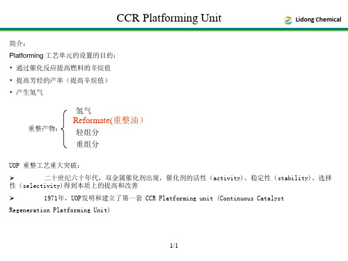
C-C-C-C-C-C
C-C-C-C-C-C-C
RON = 100
C C-C-C-C-C-C
RON = 30
RON = 95
9/9
Paraffin Cracking(裂解): Chloride
High T
Lidong Chemical
High P
C-C-C-C-C-C-C-C + H2
4.催化剂对芳烃的选择性
芳烃选择性定义为在给定的催化剂和操作情况下产生芳烃的趋势。 影响参数:操作的 苛刻度(C5+RONC)和原料组成(P、N、A)。
27/27
Lidong Chemical
5.催化剂的稳定性
催化剂的稳定性是在给定的催化剂下生焦趋势的量度。(图Ⅲ-16、17、18、19、20)
6 非直馏石脑油对催化剂稳定性的影响(Effect of Non-SRN on Catalyst Stability )
4/4
Lidong Chemical
1.2 化学反应:
环烷烃 35% 芳烃 10%
重整反应
链烃 55%
Lidong Chemical
芳烃
80%
氢气 非芳烃
20%
5/5
Naphthene Dehydrogenation(脱氢): High T
Lidong Chemical
Low P
Platenuim
Lidong Chemical 33/33
Lidong Chemical 34/34
Lidong Chemical 35/35
Lidong Chemical 36/36
Lidong Chemical 37/37
中英文对照表
APPENDIX NO. IPROCESS DESCRIPTION附件一:工艺描述1 CCR Platforming Process铂重整工艺I.1.1Advantage of CCR Platforming Process铂重整工艺的优势Recognizing the need for high octane reformate and aromatics production combined with long run lengths and high yields, UOP developed the CCR Platforming process. Although some have tried to duplicate the design, none have been able to equal it. UOP has continued to introduce new innovations which provide benefits to Refiners.由于认识对高的辛烷值重整生成油和芳烃产品的需求以及对长周期、高负荷生产的需要, UOP 开发了铂连续重整工艺。
虽然也有一些公司也尝试复制设计,但还没有一家公司与之相当。
UOP一直致力于引入使炼油厂增加效益的创新技术。
UOP was first to:- Commercialize CCR Platforming- Develop a strong spherical catalyst- Reduce the platinum content of reforming catalyst without losing yield or performance- Use innovative reactor designs such as stacked reactors with upflow center pipes and integral catalyst collectors-Design a reaction system with 3.5 kg/cm2g average reactor pressure and 2.5 kg/cm2g separator pressureUOP首创:-商业化的连续铂重整工艺-开发出了高强度的球形催化剂-减少重整催化剂中的铂含量而不降低收率和性能-应用创新的叠置式反应器、上流式中心管和集成的催化剂回收器。
Process and staged combustion apparatus for regene
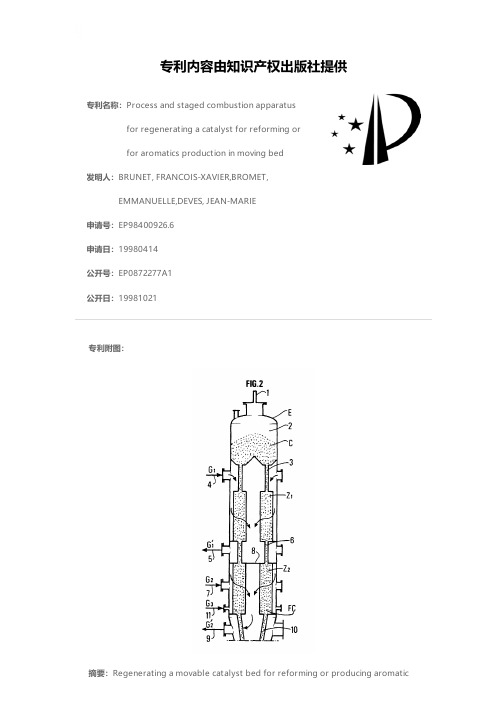
专利名称:Process and staged combustion apparatusfor regenerating a catalyst for reforming orfor aromatics production in moving bed发明人:BRUNET, FRANCOIS-XAVIER,BROMET,EMMANUELLE,DEVES, JEAN-MARIE申请号:EP98400926.6申请日:19980414公开号:EP0872277A1公开日:19981021专利内容由知识产权出版社提供专利附图:摘要:Regenerating a movable catalyst bed for reforming or producing aromatichydrocarbons, whereby the catalyst coats a support, at least one noble metal and at least one halogen, comprises use of a combustion stage with treatment for the catalyst in at least two successive combustion zones. Each combustion zone is separated from the adjacent zones in such a way as to allow the passage of the catalyst but obstruct the passage of gases. In each zone at least one gas containing oxygen is introduced and the gases produced are extracted from each zone. The severity of the operating conditions in each combustion zone increases in the direction of movement of the catalyst.申请人:INSTITUT FRANCAIS DU PETROLE地址:4, Avenue de Bois Préau 92500 Rueil Malmaison FR国籍:FR更多信息请下载全文后查看。
野油菜黄单胞菌BioC蛋白的生物信息学分析
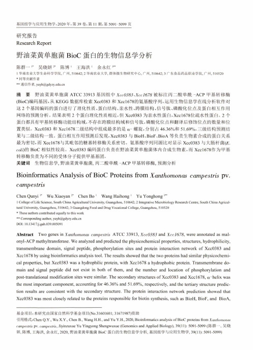
基因组学与应用生物学,2020年,第39卷,第11期,第509卜5099页研究报告Research Report野油菜黄单胞菌B ioC蛋白的生物信息学分析陈群一”吴晓妍”陈博,王海洪1余永红3"1华南农业大学生命科学学院,广州,510642; 2华南农业大学,群体微生物研宂中心,广州,510642; 3广东食品药品职业学院,广州,510520*同等贡献作者** 通信作者,**************.cn摘要野油菜黄单胞菌ATCC 33913基因组中XccO?&?、Zcc/67S被标注丙二酸单酰-A C P甲基转移酶 (BioC)编码基因,从KEGG数据库检索Xcc0383和Xccl678的氨基酸序列,运用生物信息学在线分析软件对 这2个基因编码的蛋白进行了理化性质、蛋白结构、亲水性、跨膜结构、信号肽、磷酸化位点及蛋白相互作用 网络的预测分析。
结果表明2个蛋白理化性质相近,但Xcc0383为亲水性蛋白,X ccl678位疏水性蛋白。
2个 蛋白都具有甲基转移酶功能结构域,不存在跨膜结构域和信号肽,磷酸化位点和翻译后修饰位点的数量和位 置类似。
Xcc0383和Xcc1678二级结构中组成最多的是ct-螺旋,分别占46.36%和51.69%,三级结构预测结 果与二级结构一致。
蛋白相互作用预测后发现,Xcc0383与BioH、BioF、B ioA等负责生物素合成的蛋白关系 最为密切,而X ccl678与其毗邻的糖基转移酶关系密切。
氨基酸序列同源比对显示Xcc0383与大肠杆菌(£. C〇Z〇的BioC相似性较高。
Xcc0383编码蛋白负责在野油菜黄单胞菌体内合成生物素,而Xccl678作为甲基 转移酶负责为不同的受体分子提供甲基基团。
关键词生物信息学,野油菜黄单胞菌,丙二酸单酰-A C P甲基转移酶,预测分析Bioinformatics Analysis o f BioC Proteins from Xanthomonas campestris pv. campestrisChen Qunyi '*Wu Xiaoyan2,Chen Bo1Wang Haihong1Yu Yonghong3*.1College of Life Science, South China Agricultural University, Guangzhou, 510642; 2 Integrative Microbiology Research Centre, South China Agricultural University, Guangzhou, 510642; 3 Guangdong Food and Drug Vocational College, Guangzhou, 510520* These authors contributed equally to this work**Correspondingauthor,**************.cnDOI: 10.13417/j.gab.039.005091Abstract Two genes in Xanthomonas campestris ATCC 33913, Xcc0383and Xccl678,were annotated as mal-onyl-ACP methyltransferase.We analyzed and predicted the physicochemical properties,structures,hydrophilicity, transmembrane domain,signal peptide,phosphorylation sites and protein interaction network of Xcc0383 and Xccl678 by using bioinformatics analysis tool.The results showed that the two proteins had similar physicochemical properties,but Xcc0383 was a hydrophilic protein,with X ccl678 a hydrophobic protein.Transmembrane domain and signal peptide did not exist in both of them,and the number and location of phosphorylation and post-translational modification sites were similar.The secondary structures of Xcc0383 and X ccl678, a~helix was the most important component,accounting for46.36% and 51.69%, respectively,and the tertiary structure prediction results are consistent with the secondary structure.The protein interaction network prediction showed that Xcc0383 was most closely related to the proteins responsible for biotin synthesis,such as BioH,BioF,and BioA,基金项目:本研究由国家自然科学基金项目(N〇.31601601;31671987)资助引用格式:C h e n Q.Y., W u X.Y., C h e n B.,W a n g H.H., a n d Y u Y.H., 2020, Bioinformatics analysis o f B i o C proteins f r o m似pv. c o m p e s^i s,Jiyinzuxue Y u Y i n g y o n g S h e n g w u x u e (G e n o m i c s a n d A p p l i e d Biology), 39(11): 5091-5099 (陈群一,吴晓妍,陈博,王海洪,余永红,2020,野油菜黄单胞菌B i o C蛋白的生物信息学分析,基因组学与应用生物学,39(11): 5091-5099)5092 基因组学与应用生物学etc.X ccl678 was closely related to its adjacent bined with the results of protein sequence alignment,Xcc0383 shared higher sequence identity with the E. coli BioC,compared with Xccl678. Therefore,it is speculated that the Xcc0383 was responsible for the synthesis of biotin in Xanthomonas campestris,while Xcc1678 acts as a methyltransferase responsible for providing methyl groups for other receptors.Keywords Bioinformatics,Aw^/u»no«as ccimpestris,Malonyl-ACP methyltransferase,Predictive analysis野油菜黄单胞菌野油菜致病变种t'«/n/;e你(s'pv.<Ycc),又称甘蓝黑腐病菌,属于变形菌纲,亚纲,黄单胞菌科(Xanthomonadaceae),黄单胞杆菌属C¥a/if/j〇,_as),革兰氏阴性菌。
PerfeCTa

95108 / IFU-074.1 REV 021PerfeC T a ® Multiplex qPCR SuperMix, Low ROX ™Cat No. 95108-050 Size: 50 x 50-µL reactions Store at -25ºC to - 15°C protected from light95108-200 200 x 50-µL reactions95108-01K1000 x 50-µL reactionsDescriptionPerfeC T a Multiplex qPCR SuperMix, Low ROX is a 2X concentrated, ready-to-use reaction cocktail that contains all components, except primers, probe(s), and template for real-time quantitative PCR on Applied Biosystems 7500, 7500 Fast, ViiA7 or Stratagene MX series of real-time PCR systems. The system transcends multiplex limitations of conventional PCR master mixes, enabling unbiased amplification of up to five target sequences in a single tube. Suppression of low copy amplicons by high copy reference targets in the amplification is a common problem in multiplex PCR. This can skew, or mask the apparent representation and quantification of low copy target sequences. PerfeC T a Multiplex qPCR SuperMix, Low ROX delivers dynamic range and sensitivity to multiplexed qPCR that is comparable to that for singleplex qPCR probe assays without the need for limiting or variable primer concentrations.The robust qPCR performance of Perfecta Multiplex qPCR SuperMix, Low ROX also overcomes suppression by common PCR inhibitors in blood or environmental samples, and is a highly sensitive reagent for quantification of low copy target sequences in challenging samples.A key component of this supermix is AccuStart™ Taq DNA polymerase, which contains monoclonal antibodies that bind to the polymerase and keep it inactive prior to the initial PCR denaturation step. Upon heat activation (2 minutes at 95ºC), the antibodies denature irreversibly, releasing fully active, unmodified Taq DNA polymerase. This enables specific and efficient primer extension with the convenience of room temperature reaction assembly.Instrument CompatibilityDifferent real-time PCR systems employ different strategies for the normalization of fluorescent signals and correction of well-to-well optical variations. It is critical to match the appropriate qPCR reagent to your specific instrument. PerfeC T a Multiplex qPCR SuperMix, Low ROX provides seamless integration on the Applied Biosystems 7500, 7500 Fast, ViiA™7 or Stratagene MX series of real-time PCR systems. These instruments utilize variable excitation wavelengths that are tuned to the each respective dye detection channel and provide superior sensitivities and dynamic ranges for multiplex probe applications. Your choice of probe reporter dyes and any optional internal reference dye must be matched to the excitation and emission optics of your particular instrument. Please consult the user manual for your real-time PCR system.ComponentsPerfeC T a Multiplex qPCR Supermix, Low ROX 2X reaction buffer containing optimized concentrations of MgCl 2, dNTPs (dATP, dCTP,dGTP, dTTP), AccuStart Taq DNA Polymerase, ROX Reference Dye (for 580-585 nm excitation), and stabilizers.Storage and StabilityStore components in a constant temperature freezer at -25°C to -15°C protected from light upon receipt. For lot specific expiry date, refer to package label, Certificate of Analysis or Product Specification Form.Guidelines for Multiplex qPCR:The design of highly specific primers and probes is a critical and challenging aspect of successful multiplex qPCR. Each primer and probeshould have similar thermodynamic properties to support efficient PCR amplification using a common temperature cycling program for all amplicons. The use of computer aided primer design programs is encouraged in order to minimize the potential for internal secondary structure and complementation at 3’-ends within each primer, primer pairs, and primer/probe combinations Amplicon size should be consistent for each target sequence and limited to approximately 65 - 100 bp.Limiting primer concentration for high copy genes is acceptable, but not required. A final concentration of 300 nM each primer and 100 to250 nM probe is effective for most applications. Each probe for a multiplex assay should be labeled using dyes with minimal spectral overlap and non-fluorescent quencher compounds. Matching dyes with discrete fluorescent excitation and emission optima improves the accuracy of the multicomponenting, or dye deconvolution algorithms employed by the real-time PCR analysis software.Preparation of a reaction cocktail is recommended to reduce pipetting errors and maximize assay precision. Assemble the reaction cocktailwith all required components except sample template (genomic DNA or cDNA) and dispense equal aliquots into each reaction tube. Add the DNA template to each reaction as the final step. Addition of samples as 5 to 10-µL volumes will improve assay precision.95108 / IFU-074.1 REV 022Guidelines for qPCR continued:Suggested input quantities of template are: cDNA corresponding to 10 pg to 1 µg of total RNA; 100 pg to 1 µg genomic DNAAfter sealing each reaction, vortex gently to mix contents. Centrifuge briefly to collect components at the bottom of the reaction tube.Reaction AssemblyComponentVolume for 50-µL rxn.Final ConcentrationPerfeC T a Multiplex qPCR SuperMix 25 µL 1xForward primers variable 100 – 500 nM each Reverse primers variable 100 – 500 nM each Probesvariable 100 – 250 nM eachNuclease-free water variable Template(s)5 – 10 µL variable Final Volume (µL)50 µLNote: Reaction volume can be scaled from 10 to 50 µL depending on the reaction plate (i.e. 384-well vs. 96-well) and qPCR system. Scale all components proportionally to the desired final reaction volume. When performing qPCR in 384-well plates, use reaction volumes between 10 and 15 uL. High (20-uL) volumes can impair mixing of sample template with the reaction cocktail and can compromise qPCR performance and reproducibilityCycling ProtocolIncubate complete reaction mix in a real-time thermal detection system as follows: Standard Protocol Fast Protocol Initial denaturation/activation 95ºC, 2 to 3 min 95ºC, 30s PCR Cycling (35 to 45 cycles): 95ºC, 10 to 15 s 95ºC, 5s 55 – 65ºC, 60s (collect and analyze data) 60ºC, 30s (collect and analyze data)Full activation of AccuStart Taq DNA polymerase occurs within 30 seconds at 95ºC; however, optimal initial denaturation time is template dependent and will affect qPCR efficiency and sensitivity. Amplification of genomic DNA targets benefit from a prolonged initial denaturation step (5-10 min) to fully denature and fragment the template. This minimizes the potential for renaturation of long fragments and/or repetitive sequence regions that can impair replication of the target sequence by the PCR process.Quality ControlKit components are free of contaminating DNase and RNase. PerfeC T a Multiplex qPCR SuperMix, Low ROX is functionally tested in a four-plex TaqMan qPCR using variable concentrations of one target sequence from 100 to 1 x 10⁷ copies and 1 x 10⁸ copies each of three other target sequences. Kinetic analysis must demonstrate linear resolution over six orders of dynamic range (r 2 > 0.995) and a PCR efficiency > 90%.Limited Label LicensesUse of this product signifies the agreement of any purchaser or user of the product to the following terms:1. The product may be used solely in accordance with the protocols provided with the product and this manual and for use with components contained in the kitonly. QIAGEN Beverly, Inc. grants no license under any of its intellectual property to use or incorporate the enclosed components of this kit with any components not included within this kit except as described in the protocols provided with the product, this manual, and additional protocols available at . Some of these additional protocols have been provided by Quantabio product users. These protocols have not been thoroughly tested or optimized by QIAGEN Beverly, Inc.. QIAGEN Beverly, Inc. neither guarantees them nor warrants that they do not infringe the rights of third-parties.2. Other than expressly stated licenses, QIAGEN Beverly, Inc. makes no warranty that this kit and/or its use(s) do not infringe the rights of third-parties.3. This kit and its components are licensed for one-time use and may not be reused, refurbished, or resold.4. QIAGEN Beverly, Inc. specifically disclaims any other licenses, expressed or implied other than those expressly stated.5. The purchaser and user of the kit agree not to take or permit anyone else to take any steps that could lead to or facilitate any acts prohibited above. QIAGEN Beverly, Inc. may enforce the prohibitions of this Limited License Agreement in any Court, and shall recover all its investigative and Court costs, including attorney fees, in any action to enforce this Limited License Agreement or any of its intellectual property rights relating to the kit and/or its components.©2018 QIAGEN Beverly Inc. 100 Cummings Center Suite 407J Beverly, MA 01915 Quantabio brand products are manufactured by QIAGEN, Beverly Inc.Intended for molecular biology applications. This product is not intended for the diagnosis, prevention or treatment of a disease.PerfeC T a and AccuStart are trademarks of QIAGEN Beverly, Inc.. TaqMan is a registered trademark of Roche Molecular Systems, Inc. Applied Biosystems , ViiA and ROX are trademarks of Life Technologies Corporation. Stratagene, MX3000P, MX3005P and MX4000 are trademarks of Agilent Technologies, Inc .。
萌物突袭,辅助制作满足一天活力的幸福味道

萌物突袭,辅助制作满足一天活力的幸福味道
Vati_赵
【期刊名称】《工业设计》
【年(卷),期】2022()5
【摘要】这是一款无线恒温辅食碗,该辅食碗立意独特,就像一只巨嘴鸟,将自己的一切都赐予了幼鸟,它是爱的象征,就像妈妈一样对小孩进行无微不至的照顾。
【总页数】1页(P10-10)
【作者】Vati_赵
【作者单位】不详
【正文语种】中文
【中图分类】G63
【相关文献】
1.仙人掌醇溶物的超声波辅助提取及其对食品腐败菌的抑制作用研究
2.银杏叶提取物对酪氨酸酶活力的抑制作用
3.计算机辅助设计与辅助制作纳米复合物陶瓷嵌体边缘微渗漏的研究
4.珍珠梅提取物对二乙基亚硝胺所致大鼠肝脏癌前病变的抑制作用及抗氧化活力的影响(英文)
5.计算机辅助设计与制作的聚合物渗透陶瓷桩核与金属桩核在牙体缺损修复中的比较
因版权原因,仅展示原文概要,查看原文内容请购买。
- 1、下载文档前请自行甄别文档内容的完整性,平台不提供额外的编辑、内容补充、找答案等附加服务。
- 2、"仅部分预览"的文档,不可在线预览部分如存在完整性等问题,可反馈申请退款(可完整预览的文档不适用该条件!)。
- 3、如文档侵犯您的权益,请联系客服反馈,我们会尽快为您处理(人工客服工作时间:9:00-18:30)。
Net Vapor (H2 enriched)
High-Purity H2
PSA
Fuel Gas
Lean Gas
Recycle Vapor
Vapor
Tail Gas
RecoveryMax System
LPG
Reactor Effluent
Separation
Recontacting
Fractionation
17
UOP 解决方案能满足严格的环保规范
• 用一个小的氯吸附罐除去再生烟气中 的氯化氢,进一步减少氯化物;
• 应用加热炉或焚烧炉以减少吸附剂床 层出口 非甲烷烃类含量;
Burn Zone Gas > 1000 ppm HCl
Catalyst Regenerator
Rx
Rx
Rx Chloride
Agent Rx
Fresh Catalyst
Naphtha Feed from
Treating
Fired Heaters
有效脱除氯化物,且无废产品生成
15
15
Reduction Zone Effluent Gas (RZEG) Chlorsorb System
• UOP进行了大量而广泛的计算来确保最高的可靠性
8
8
2017 CatMax Internals Qualification
UOP 7838C-8
双U型管加热炉设计基于UOP“U型”炉管设计经验
9
• 具有40多年在重整或其他技术中“U 型” 加热炉管 主要类型的设计经验,
– 卓越的机械灵活性; – 压降低,热回收率高;
1
UOP连续催化重整技术应用经验
世界领先技术专利商
经验
自1971年超过263套装置在运行, 55套装置在设 计和建设中
市场需求量
过去10年- 75 % 2016 – 72%
规模超过200万吨/年的装置
16套运行装置中有规模超过400万吨/年 14套在设计建设中的装置有规模超过480万吨/年
25
100%
Structure
Bag
Dust
Collector
H
Dust Collector
Improved
Regeneration Tower Inner
Screen Design
Booster Gas H2 Reduction Zone
Last Reactor
Disengaging Hopper
Regeneration Gas Blower
4
4
CatMax™ 内件
提高收率
板式换热器
反应器 物料
循环气
CycleMax™ III CCR
石脑油进料
加热炉整合设计
提高收率,减少投资,IRR增加 2 - 6 %
UOP CatMax重整反应器内构件
5
5
• 什么是CatMax反应器内构件? – 分段设计的矩形楔形扇形桶 – 新一代高强度扇形桶设计,在之前基础上进行了少量的 优化
3
UOP 7838C-3
Capacity (KMTA)
4,500 4,000 3,500
运行的大型连续催化重整装置
UOP Operating UOP Original Design
3,000
2,500
2,000
1,500 1970
1980
1990
2000
试运行年
2010
2020
设计改进 – 提高收率,减少投资成本和运行成本
Other
35624324225
UOP
18 15 10 9 11 5 12 9 8 5 13
UOP SOD 86% 75% 63% 82% 73% 63% 86% 69% 80% 71% 72%
1,200 – 2,000 56 套
世界上85% 的连续催化重整装置都使用UOP的技术
UOP 连续催化重整技术在中国的商业化经验
Liquid
Liquid (C4+ enriched)
Reformate
>95% H2 Recovery >85% LPG Recovery
UOP最大化LPG回收率的 RecoveryMax 系统
12
12
• 增加RecoveryMax 系统 且应用 UOP 专 有 PSA 尾循环流程可使LPG回收率达到 90%;
Reactor Effluent
Separation
Recontacting
Fractionation
LPG Reformate
Liquid
Liquid (C4+ enriched)
<90% H2 Recovery <55% LPG Recovery
UOP RecoveryMaxTM System
Lean Gas Recycle
改进的设计可增加收率,提高可靠性, 最大化在线率
Regenerator Vent Gas (RVG) Chlorsorb 系统
14
14
如何工作:
通过排放气和废催化剂吸附剂的逆 流接触来回收氯化物;
Disengaging Hopper
Vent Gas < 30 ppm HCl
好处:
• 没有碱处理费用; • 没有液废或固废; • 最小水耗量; • 由于大量回收氯化物可减少注氯量(减少70%)
11
11
UOP 7838C-11
Standard Recontact & Fractionation
Tail Gas Recycle
Fuel
Gas High-Purity
Light Ends Recycle
H2
Recycle Vapor
Vapor
Net Vapor (H2 enriched)
PSA
Tail Gas
•特点 – 消除了低流量的固气盲区 – 相对于传统的D型扇形桶提高了机械强度(高达10倍) – 在反应器壳体不变的情况下,楔形扇形桶增加了 10%~20%的催化剂装填量
改进的功能提供显著的效益
D-型扇形桶 OptiMiserTM CatMax
扇形桶
内件
UOP CatMax具有显著的优势
6
6
• 对于330万吨/年的重整装置可减少1000万元的安装成 本
CatMax 内件 基准 基准 -2~ 3 - 10 - 40
CatMax 内件可降低整体建设费用并能提高装置可靠性
UOP 广泛的经验确保CatMax最高的可靠性和工艺性能
• UOP在重整领域有着他人无法比拟的经验,使得我们可以不断的 对扇形桶的设计进行改进以加强装置的性能 – UOP向制造商提供高强度扇形桶的设计规格书 – 扇形桶仅仅是整个系统的一部分——UOP为整个反应器系统 进行设计以确保最佳的工艺性能以及最高的可靠性; – 锥形内件在多年里到很多用途,包括连续催化重整再生器内 外网 – UOP在过去40多年中一直做着类似的改进;
• UOP 对重整加热炉设计细节和需求非常熟悉;
• UOP提供详细的加热炉技术规格书,其中包括如 工艺和机械的所有需求 ;
• 基于丰富的U型炉管设计经验,UOP 开发了双U型 炉管的设计
双U型加热炉微小的设计改进到商业化的加热炉管设计
UOP 重整加热炉设计改进
10
加热炉并联
加热炉串联
双U型管加热炉
好处:
• 更容易从代生催化剂中除去油气; • 在净排放气中减少氯化物含量; • 降低装置内氯吸附罐内吸附剂的藏量; • 补充吸附剂成本降低50% ;
Chlorsorb 系统被广泛认可
在设计、施工和操作中的 Chlorsorb 系统数量
总计 = 110
16
16
自 2011年,UOP授权的设计中超过85%应用Chlorsorb; 中国项目100%应用Chlorsorb
氢气, MTD
143
143
LPG, MTD
64
117
燃料气, MTD
170
125
界区内 安装成本
基准
+ 6 $MM
公用工程
基准
+ 0 $MM/yr
毛利润
基准
+ 3 $MM/yr
NPV
基准
+ 9 $MM
基准: 规模120万吨/年的连续重整新装置。所有工况包含PSA(不 包括膜)
LPG 产量提高180%
Chloride
Regenerated Cat Dust Collector
Dust Collector
Robust Lock Hopper System
RZEG Chlorsorb
Catalyst Collector
N2
Air
N2 Booster Gas H2
Lock Hopper System
Improved Catalyst Chlorination
- 减少约5%的反应器框架及相关配管成本(反应器高度更低 配管长度更小)
- 降低对基础和钢结构的要求(更轻) - 更短的输送管线及更少的管线移动
• 增加液收 • 减少反应器压降 • 改进气相分布以优化水力学 • 更高的可靠性,减少检修时间和成本
CatMax内件
330万吨/年的重整装置可减少1000多万RMB的安装成本
• 包含一个 PolysepTM 膜系统,再加上 UOP PSA 装置可使回收率达到: – 氢气 >98% – LPG >95%
新装置案例分析: UOP RecoveryMax vs. Standard Recontact & Fractionation Scheme