MAX5432中文资料
Maxim MAX25430控制器和保护器方案

Maxim MAX25430汽车100W USB-PD降-升压端口控制器和保护器解决方案Maxim公司的MAX25430组合了汽车级的降压-升压控制器(驱动高达5.0A), B-PD模拟前端(AFE),支持先前的USB充电和用于USB主或DFP应用的USB Type-C™保护.USB Type-C保护开关提供汽车系统级ESD和24V短路保护,用于D+, D-, CC1, CC2和VCONN引脚.器件还支持先前的USB 2.0充电模式包括BC1.2, Apple® 2.4A, Apple CarPlay®, Apple MFi和USB On-The-Go (OTG).MAX25430B集成了USB-PD AFE,支持USB-IF Type-C端口控制器接口(TCPCI)指标,并能和应用中的任一I2C主接口.MAX25430A为外接USB-PD控制器提供CC信号直通保护.输入工作电压4.5V到36V,固定PDO 5V,9V,15V和20V 高达5.0A,开关频率为220kHz, 300kHz或400kHz.器件集成±15kV Air, ±8kV接触ISO 10605和IEC 61000-4-2 ESD保护.工作温度-40°C到125°C,40引脚(6mmx6mm) TQFN封装,AEC-Q100和AEC-Q006资质.主要用在USB集线器,多媒体集线器和突破盒,专用充电模块,后座娱乐模块.本文介绍了MAX25430主要优势和特性,简化框图和功能框图,降压/升压框图,USB Type-C功能框图,数据交换和电荷检测框图,USB供电(PD)保护框图,应用框图以及评估板MAX25430 EVKIT主要优势和特性,电路图,材料清单和PCB设计图.The MAX25430 combines an automotive-grade buck-boost controller capable of driving up to 5.0A, a USB-PD Analog Front-End (AFE), Legacy USB Charging support and USB Type-C™ protection for USB host or DFP applications. The USB Type-C protection switches provide automotive system-level ESD and 24V short-circuit protection for D+, D-, CC1, CC2, and VCONN. The device also supports legacy USB 2.0 charging modes including BC1.2, Apple® 2.4A, Apple CarPlay®, Apple MFi and USB On-The-Go (OTG). The MAX25430B integrates a USB-PD AFE which supports the USB-IF Type-C Port Controller Interface (TCPCI) specification and can interface with any I2C Master in the application.The MAX25430A provides CC signal passthrough protection for an external USB-PD controller.G-Suffix devices include intelligent detection and protection to avoid high short-circuit currents flowing from thecar battery through the cable shield to ground during faultevents, preventing car module damage. The MAX25430 EVKIT and collateral provides a convenient platform to the design engineer for rapid evaluation with reduced test and firmware development time. The MAX25430 is available in a small 6mm x 6mm 40-pin TQFN package and requires very few external components.MAX25430主要优势和特性:●USB-PD PHY That is TCPCI Standard for Use withAny Low-Cost I2C Master Such as Hub IC, MCU orSOC (MAX25430B)•Ground-Offset-Adjusted BMC PHY for MaximumSignal-to-Noise Ratio●Non-TCPC Versions Available for Protecting ExternalUSB-PD Controller (MAX25430A)●Integrated Buck-Boost Controller for External H-bridge•4.5V to 36V Input Operating Range•Fixed PDO 5V, 9V, 15V and 20V up to 5.0A•220kHz, 300kHz or 400kHz Switching Frequency•External Frequency Synchronization and SpreadSpectrum for Reduced EMI●Integrated and User-Programmable Buck-BoostOutput Voltage Adjustment up to 500mΩ of CableResistance●Highest Performance, Safest, and Lowest CostPassenger Cable-Shield Short-to-Battery Protection •Minimizes Short-Circuit Currents with a Small,Single-FET Solution●Integrated 3.0V to 5.5V 1W Smart, Reliable VCONNSwitch with Protection●Integrated 24V Protection on HVD+, HVD-, HVCC1and HVCC2●Integrated Legacy USB 2.0 Charging Supportincluding BC1.2, Apple CarPlay, MFi R33, and OTG ●Integrated ±15kV Air, ±8kV Contact ISO 10605 andIEC 61000-4-2 ESD Protection●-40°C to 125°C Operating Temperature Range●40-Pin (6mm x 6mm) TQFN Package with EP●AEC-Q100 and AEC-Q006 QualifiedMAX25430应用:●USB Hubs, Breakout Boxes and Multimedia Hu bs●Dedicated Charging Modules●Rear-Seat Entertainment Modules图1.MAX25430简化框图图2. MAX25430功能框图图3. MAX25430降压/升压框图图4. MAX25430 USB Type-C功能框图图5. MAX25430数据交换和电荷检测框图图6. MAX25430 USB供电(PD)保护框图图7. MAX25430应用框图(1)图8. MAX25430应用框图(2)。
MAX系列芯片大全

MAXIM/DALLAS 中文数据资料DS12CR887, DS12R885, DS12R887 RTC,带有恒压涓流充电器DS1870 LDMOS RF功放偏置控制器DS1921L-F5X Thermochron iButtonDS1923 温度/湿度记录仪iButton,具有8kB数据记录存储器DS1982, DS1982-F3, DS1982-F5 1k位只添加iButton?DS1990A 序列号iButtonDS1990R, DS1990R-F3, DS1990R-F5 序列号iButtonDS1991 多密钥iButtonDS2129 LVD SCSI 27线调节器DS2401 硅序列号DS2406 双通道、可编址开关与1k位存储器DS2408 1-Wire、8通道、可编址开关DS2411 硅序列号,带有VCC输入DS2413 1-Wire双通道、可编址开关DS2430A 256位1-Wire EEPROMDS2431 1024位、1-Wire EEPROMDS2480B 串行、1-Wire线驱动器,带有负荷检测DS2482-100 单通道1-Wire主控制器DS2482-100 勘误表PDF: 2482-100A2DS2482-800, DS2482S-800 八通道1-Wire主控制器DS2482-800 勘误表PDF: 2482-800A2DS2502 1k位只添加存储器DS2505 16k位只添加存储器DS28E04-100 4096位、可寻址、1-Wire EEPROM,带有PIODS3170DK DS3/E3单芯片收发器开发板DS3231, DS3231S 高精度、I2C集成RTC/TCXO/晶振DS33Z44 四路以太网映射器DS3902 双路、非易失、可变电阻器,带有用户EEPROMDS3906 三路、非易失、小步长调节可变电阻与存储器DS3984 4路冷阴极荧光灯控制器DS4302 2线、5位DAC,提供三路数字输出DS80C400-KIT DS80C400评估套件DS80C410, DS80C411 具有以太网和CAN接口的网络微控制器DS80C410 勘误表PDF: 80C410A1DS89C430, DS89C440, DS89C450 超高速闪存微控制器DS89C430 勘误表PDF: 89C430A2DS89C440 勘误表PDF: 89C440A2DS89C450 勘误表PDF: 89C450A2DS89C430 勘误表PDF: 89C430A3DS89C440 勘误表PDF: 89C440A3DS89C450 勘误表PDF: 89C450A3DS89C430 勘误表PDF: 89C430A5DS89C440 勘误表PDF: 89C440A5DS89C450 勘误表PDF: 89C450A5DS9090K 1-Wire器件评估板, B版DS9097U-009, DS9097U-E25, DS9097U-S09 通用1-Wire COM端口适配器DS9490, DS9490B, DS9490R USB至1-Wire/iButton适配器MAX1034, MAX1035 8/4通道、±VREF多量程输入、串行14位ADCMAX1072, MAX1075 1.8Msps、单电源、低功耗、真差分、10位ADCMAX1076, MAX1078 1.8Msps、单电源供电、低功耗、真差分、10位ADC,内置电压基准MAX1146, MAX1147, MAX1148, MAX1149 多通道、真差分、串行、14位ADCMAX1149EVKIT MAX1149评估板/评估系统MAX1220, MAX1257, MAX1258 12位、多通道ADC/DAC,带有FIFO、温度传感器和GPIO端口MAX1224, MAX1225 1.5Msps、单电源、低功耗、真差分、12位ADCMAX1258EVKIT MAX1057, MAX1058, MAX1257, MAX1258评估板/评估系统MAX1274, MAX1275 1.8Msps、单电源、低功耗、真差分、12位ADCMAX13000E, MAX13001E, MAX13002E, MAX13003E, MAX13004E, MAX13005E 超低电压电平转换器MAX1302, MAX1303 8/4通道、±VREF多量程输入、串行16位ADCMAX1304, MAX1305, MAX1306, MAX1308, MAX1309, MAX1310, MAX1312, MAX1313,MAX1314 8/4/2通道、12位、同时采样ADC,提供±10V、±5V或0至+5V模拟输入范围MAX13050, MAX13052, MAX13053, MAX13054 工业标准高速CAN收发器,具有±80V故障保护MAX13080E, MAX13081E, MAX13082E, MAX13083E, MAX13084E, MAX13085E, MAX13086E, MAX13087E, MAX13088E, MAX13089E +5.0V、±15kV ESD保护、失效保护、热插拔、RS-485/RS-422收发器MAX13101E, MAX13102E, MAX13103E, MAX13108E 16通道、带有缓冲的CMOS逻辑电平转换器MAX1334, MAX1335 4.5Msps/4Msps、5V/3V、双通道、真差分10位ADCMAX1336, MAX1337 6.5Msps/5.5Msps、5V/3V、双通道、真差分8位ADCMAX13481E, MAX13482E, MAX13483E ±15kV ESD保护USB收发器, 外部/内部上拉电阻MAX1350, MAX1351, MAX1352, MAX1353, MAX1354, MAX1355, MAX1356, MAX1357 双路、高端、电流检测放大器和驱动放大器MAX1450 低成本、1%精确度信号调理器,用于压阻式传感器MAX1452 低成本、精密的传感器信号调理器MAX1487, MAX481, MAX483, MAX485, MAX487, MAX488, MAX489, MAX490, MAX491 低功耗、限摆率、RS-485/RS-422收发器MAX1492, MAX1494 3位半和4位半、单片ADC,带有LCD驱动器MAX1494EVKIT MAX1493, MAX1494, MAX1495评估板/评估系统MAX1497, MAX1499 3位半和4位半、单片ADC,带有LED驱动器和μC接口MAX1499EVKIT MAX1499评估板/评估系统MAX15000, MAX15001 电流模式PWM控制器, 可调节开关频率MAX1515 低电压、内置开关、降压/DDR调节器MAX1518B TFT-LCD DC-DC转换器, 带有运算放大器MAX1533, MAX1537 高效率、5路输出、主电源控制器,用于笔记本电脑MAX1533EVKIT MAX1533评估板MAX1540A, MAX1541 双路降压型控制器,带有电感饱和保护、动态输出和线性稳压器MAX1540EVKIT MAX1540评估板MAX1551, MAX1555 SOT23、双输入、USB/AC适配器、单节Li+电池充电器MAX1553, MAX1554 高效率、40V、升压变换器,用于2至10个白光LED驱动MAX1556, MAX1557 16μA IQ、1.2A PWM降压型DC-DC转换器MAX1556EVKIT MAX1556EVKIT评估板MAX1558, MAX1558H 双路、3mm x 3mm、1.2A/可编程电流USB开关,带有自动复位功能MAX1586A, MAX1586B, MAX1586C, MAX1587A, MAX1587C 高效率、低IQ、带有动态内核的PMIC,用于PDA和智能电话MAX16801A/B, MAX16802A/B 离线式、DC-DC PWM控制器, 用于高亮度LED驱动器MAX1858A, MAX1875A, MAX1876A 双路180°异相工作的降压控制器,具有排序/预偏置启动和POR MAX1870A 升/降压Li+电池充电器MAX1870AEVKIT MAX1870A评估板MAX1874 双路输入、USB/AC适配器、1节Li+充电器,带OVP与温度调节MAX1954A 低成本、电流模式PWM降压控制器,带有折返式限流MAX1954AEVKIT MAX1954A评估板MAX19700 7.5Msps、超低功耗模拟前端MAX19700EVKIT MAX19700评估板/评估系统MAX19705 10位、7.5Msps、超低功耗模拟前端MAX19706 10位、22Msps、超低功耗模拟前端MAX19707 10位、45Msps、超低功耗模拟前端MAX19708 10位、11Msps、超低功耗模拟前端MAX2041 高线性度、1700MHz至3000MHz上变频/下变频混频器,带有LO缓冲器/开关MAX2043 1700MHz至3000MHz高线性度、低LO泄漏、基站Rx/Tx混频器MAX220, MAX222, MAX223, MAX225, MAX230, MAX231, MAX232, MAX232A, MAX233,MAX233A, MAX234, MAX235, MAX236, MAX237, MAX238, MAX239, MAX240, MAX241,MAX242, MAX243, MAX244, MAX245, MAX246, MAX247, MAX248, MAX249 +5V供电、多通道RS-232驱动器/接收器MAX2335 450MHz CDMA/OFDM LNA/混频器MAX2370 完备的、450MHz正交发送器MAX2370EVKIT MAX2370评估板MAX2980 电力线通信模拟前端收发器MAX2986 集成电力线数字收发器MAX3013 +1.2V至+3.6V、0.1μA、100Mbps、8路电平转换器MAX3205E, MAX3207E, MAX3208E 双路、四路、六路高速差分ESD保护ICMAX3301E, MAX3302E USB On-the-Go收发器与电荷泵MAX3344E, MAX3345E ±15kV ESD保护、USB收发器,UCSP封装,带有USB检测MAX3394E, MAX3395E, MAX3396E ±15kV ESD保护、大电流驱动、双/四/八通道电平转换器, 带有加速电路MAX3535E, MXL1535E +3V至+5V、提供2500VRMS隔离的RS-485/RS-422收发器,带有±15kV ESD保护MAX3570, MAX3571, MAX3573 HI-IF单芯片宽带调谐器MAX3643EVKIT MAX3643评估板MAX3645 +2.97V至+5.5V、125Mbps至200Mbps限幅放大器,带有信号丢失检测器MAX3645EVKIT MAX3645评估板MAX3654 47MHz至870MHz模拟CATV互阻放大器MAX3654EVKIT MAX3654评估板MAX3657 155Mbps低噪声互阻放大器MAX3658 622Mbps、低噪声、高增益互阻前置放大器MAX3735, MAX3735A 2.7Gbps、低功耗、SFP激光驱动器MAX3737 多速率激光驱动器,带有消光比控制MAX3737EVKIT MAX3737评估板MAX3738 155Mbps至2.7Gbps SFF/SFP激光驱动器,带有消光比控制MAX3744, MAX3745 2.7Gbps SFP互阻放大器,带有RSSIMAX3744EVKIT, MAX3745EVKIT MAX3744, MAX3745评估板MAX3748, MAX3748A, MAX3748B 紧凑的、155Mbps至4.25Gbps限幅放大器MAX3785 6.25Gbps、1.8V PC板均衡器MAX3787EVKIT MAX3787评估板MAX3793 1Gbps至4.25Gbps多速率互阻放大器,具有光电流监视器MAX3793EVKIT MAX3793评估板MAX3805 10.7Gbps自适应接收均衡器MAX3805EVKIT MAX3805评估板MAX3840 +3.3V、2.7Gbps双路2 x 2交叉点开关MAX3841 12.5Gbps CML 2 x 2交叉点开关MAX3967 270Mbps SFP LED驱动器MAX3969 200Mbps SFP限幅放大器MAX3969EVKIT MAX3969评估板MAX3982 SFP铜缆预加重驱动器MAX3983 四路铜缆信号调理器MAX3983EVKIT MAX3983评估板MAX3983SMAEVKIT MAX3983 SMA连接器评估板MAX4079 完备的音频/视频后端方案MAX4079EVKIT MAX4079评估板MAX4210, MAX4211 高端功率、电流监视器MAX4210EEVKIT MAX4210E、MAX4210A/B/C/D/F评估板MAX4211EEVKIT MAX4211A/B/C/D/E/F评估板MAX4397 用于双SCART连接器的音频/视频开关MAX4397EVKIT MAX4397评估系统/评估板MAX4411EVKIT MAX4411评估板MAX4729, MAX4730 低电压、3.5、SPDT、CMOS模拟开关MAX4754, MAX4755, MAX4756 0.5、四路SPDT开关,UCSP/QFN封装MAX4758, MAX4759 四路DPDT音频/数据开关,UCSP/QFN封装MAX4760, MAX4761 宽带、四路DPDT开关MAX4766 0.075A至1.5A、可编程限流开关MAX4772, MAX4773 200mA/500mA可选的限流开关MAX4795, MAX4796, MAX4797, MAX4798 450mA/500mA限流开关MAX4826, MAX4827, MAX4828, MAX4829, MAX4830, MAX4831 50mA/100mA限流开关, 带有空载标记, μDFN封装MAX4832, MAX4833 100mA LDO,带有限流开关MAX4834, MAX4835 250mA LDO,带有限流开关MAX4836, MAX4837 500mA LDO,带有限流开关MAX4838A, MAX4840A, MAX4842A 过压保护控制器,带有状态指示FLAGMAX4850, MAX4850H, MAX4852, MAX4852H 双路SPDT模拟开关,可处理超摆幅信号MAX4851, MAX4851H, MAX4853, MAX4853H 3.5/7四路SPST模拟开关,可处理超摆幅信号MAX4854 7四路SPST模拟开关,可处理超摆幅信号MAX4854H, MAX4854HL 四路SPST、宽带、信号线保护开关MAX4855 0.75、双路SPDT音频开关,具有集成比较器MAX4864L, MAX4865L, MAX4866L, MAX4867, MAX4865, MAX4866 过压保护控制器,具有反向保护功能MAX4880 过压保护控制器, 内置断路开关MAX4881, MAX4882, MAX4883, MAX4884 过压保护控制器, 内部限流, TDFN封装MAX4901, MAX4902, MAX4903, MAX4904, MAX4905 低RON、双路SPST/单路SPDT、无杂音切换开关, 可处理负电压MAX4906, MAX4906F, MAX4907, MAX4907F 高速/全速USB 2.0开关MAX5033 500mA、76V、高效率、MAXPower降压型DC-DC变换器MAX5042, MAX5043 双路开关电源IC,集成了功率MOSFET和热插拔控制器MAX5058, MAX5059 可并联的副边同步整流驱动器和反馈发生器控制ICMAX5058EVKIT MAX5051, MAX5058评估板MAX5062, MAX5062A, MAX5063, MAX5063A, MAX5064, MAX5064A, MAX5064B 125V/2A、高速、半桥MOSFET驱动器MAX5065, MAX5067 双相、+0.6V至+3.3V输出可并联、平均电流模式控制器MAX5070, MAX5071 高性能、单端、电流模式PWM控制器MAX5072 2.2MHz、双输出、降压或升压型转换器,带有POR和电源失效输出MAX5072EVKIT MAX5072评估板MAX5074 内置MOSFET的电源IC,用于隔离型IEEE 802.3af PD和电信电源MAX5078 4A、20ns、MOSFET驱动器MAX5084, MAX5085 65V、200mA、低静态电流线性稳压器, TDFN封装MAX5088, MAX5089 2.2MHz、2A降压型转换器, 内置高边开关MAX5094A, MAX5094B, MAX5094C, MAX5094D, MAX5095A, MAX5095B, MAX5095C 高性能、单端、电流模式PWM控制器MAX5128 128抽头、非易失、线性变化数字电位器, 采用2mm x 2mm μDFN封装MAX5417, MAX5417L, MAX5417M, MAX5417N, MAX5417P, MAX5418, MAX5419 256抽头、非易失、I2C接口、数字电位器MAX5417LEVKIT MAX5417_, MAX5418_, MAX5419_评估板/评估系统MAX5477, MAX5478, MAX5479 双路、256抽头、非易失、I2C接口、数字电位器MAX5478EVKIT MAX5477/MAX5478/MAX5479评估板/评估系统MAX5490 100k精密匹配的电阻分压器,SOT23封装MAX5527, MAX5528, MAX5529 64抽头、一次性编程、线性调节数字电位器MAX5820 双路、8位、低功耗、2线、串行电压输出DACMAX5865 超低功耗、高动态性能、40Msps模拟前端MAX5920 -48V热插拔控制器,外置RsenseMAX5921, MAX5939 -48V热插拔控制器,外置Rsense、提供较高的栅极下拉电流MAX5932 正电源、高压、热插拔控制器MAX5932EVKIT MAX5932评估板MAX5936, MAX5937 -48V热插拔控制器,可避免VIN阶跃故障,无需RSENSEMAX5940A, MAX5940B IEEE 802.3af PD接口控制器,用于以太网供电MAX5940BEVKIT MAX5940B, MAX5940D评估板MAX5941A, MAX5941B 符合IEEE 802.3af标准的以太网供电接口/PWM控制器,适用于用电设备MAX5945 四路网络电源控制器,用于网络供电MAX5945EVKIT, MAX5945EVSYS MAX5945评估板/评估系统MAX5953A, MAX5953B, MAX5953C, MAX5953D IEEE 802.3af PD接口和PWM控制器,集成功率MOSFETMAX6640 2通道温度监视器,提供双路、自动PWM风扇速度控制器MAX6640EVKIT MAX6640评估系统/评估板MAX6641 兼容于SMBus的温度监视器,带有自动PWM风扇速度控制器MAX6643, MAX6644, MAX6645 自动PWM风扇速度控制器,带有过温报警输出MAX6678 2通道温度监视器,提供双路、自动PWM风扇速度控制器和5个GPIOMAX6695, MAX6696 双路远端/本地温度传感器,带有SMBus串行接口MAX6877EVKIT MAX6877评估板MAX6950, MAX6951 串行接口、+2.7V至+5.5V、5位或8位LED显示驱动器MAX6966, MAX6967 10端口、恒流LED驱动器和输入/输出扩展器,带有PWM亮度控制MAX6968 8端口、5.5V恒流LED驱动器MAX6969 16端口、5.5V恒流LED驱动器MAX6970 8端口、36V恒流LED驱动器MAX6977 8端口、5.5V恒流LED驱动器,带有LED故障检测MAX6978 8端口、5.5V恒流LED驱动器,带有LED故障检测和看门狗MAX6980 8端口、36V恒流LED驱动器, 带有LED故障检测和看门狗MAX6981 8端口、36V恒流LED驱动器, 带有LED故障检测MAX7030 低成本、315MHz、345MHz和433.92MHz ASK收发器, 带有N分频PLLMAX7032 低成本、基于晶振的可编程ASK/FSK收发器, 带有N分频PLLMAX7317 10端口、SPI接口输入/输出扩展器,带有过压和热插入保护MAX7319 I2C端口扩展器,具有8路输入,可屏蔽瞬态检测MAX7320 I2C端口扩展器, 带有八个推挽式输出MAX7321 I2C端口扩展器,具有8个漏极开路I/O口MAX7328, MAX7329 I2C端口扩展器, 带有八个I/O口MAX7347, MAX7348, MAX7349 2线接口、低EMI键盘开关和发声控制器MAX7349EVKIT MAX7349评估板/仿真: MAX7347/MAX7348MAX7375 3引脚硅振荡器MAX7381 3引脚硅振荡器MAX7389, MAX7390 微控制器时钟发生器, 带有看门狗MAX7391 快速切换时钟发生器, 带有电源失效检测MAX7445 4通道视频重建滤波器MAX7450, MAX7451, MAX7452 视频信号调理器,带有AGC和后肩钳位MAX7452EVKIT MAX7452评估板MAX7462, MAX7463 单通道视频重建滤波器和缓冲器MAX8505 3A、1MHz、1%精确度、内置开关的降压型调节器,带有电源就绪指示MAX8524, MAX8525 2至8相VRM 10/9.1 PWM控制器,提供精密的电流分配和快速电压定位MAX8525EVKIT MAX8523, MAX8525评估板MAX8533 更小、更可靠的12V、Infiniband兼容热插拔控制器MAX8533EVKIT MAX8533评估板MAX8545, MAX8546, MAX8548 低成本、宽输入范围、降压控制器,带有折返式限流MAX8550, MAX8551 集成DDR电源方案,适用于台式机、笔记本电脑及图形卡MAX8550EVKIT MAX8550, MAX8550A, MAX8551评估板MAX8552 高速、宽输入范围、单相MOSFET驱动器MAX8553, MAX8554 4.5V至28V输入、同步PWM降压控制器,适合DDR端接和负载点应用MAX8563, MAX8564 ±1%、超低输出电压、双路或三路线性n-FET控制器MAX8564EVKIT MAX8563, MAX8564评估板MAX8566 高效、10A、PWM降压调节器, 内置开关MAX8570, MAX8571, MAX8572, MAX8573, MAX8574, MAX8575 高效LCD升压电路,可True ShutdownMAX8571EVKIT MAX8570, MAX8571, MAX8572, MAX8573, MAX8574, MAX8575评估板MAX8576, MAX8577, MAX8578, MAX8579 3V至28V输入、低成本、迟滞同步降压控制器MAX8594, MAX8594A 5路输出PMIC,提供DC-DC核电源,用于低成本PDAMAX8594EVKIT MAX8594评估板MAX8632 集成DDR电源方案,适用于台式机、笔记本电脑和图形卡MAX8632EVKIT MAX8632评估板MAX8702, MAX8703 双相MOSFET驱动器,带有温度传感器MAX8707 多相、固定频率控制器,用于AMD Hammer CPU核电源MAX8716, MAX8717, MAX8757 交叉工作、高效、双电源控制器,用于笔记本电脑MAX8716EVKIT MAX8716评估板MAX8717EVKIT MAX8717评估板MAX8718, MAX8719 高压、低功耗线性稳压器,用于笔记本电脑MAX8725EVKIT MAX8725评估板MAX8727 TFT-LCD升压型、DC-DC变换器MAX8727EVKIT MAX8727评估板MAX8729 固定频率、半桥CCFL逆变控制器MAX8729EVKIT MAX8729评估板MAX8732A, MAX8733A, MAX8734A 高效率、四路输出、主电源控制器,用于笔记本电脑MAX8737 双路、低电压线性稳压器, 外置MOSFETMAX8737EVKIT MAX8737评估板MAX8738 EEPROM可编程TFT VCOM校准器, 带有I2C接口MAX8740 TFT-LCD升压型、DC-DC变换器MAX8743 双路、高效率、降压型控制器,关断状态下提供高阻MAX8751 固定频率、全桥、CCFL逆变控制器MAX8751EVKIT MAX8751评估板MAX8752 TFT-LCD升压型、DC-DC变换器MAX8758 具有开关控制和运算放大器的升压调节器, 用于TFT LCDMAX8758EVKIT MAX8758评估板MAX8759 低成本SMBus CCFL背光控制器MAX8760 双相、Quick-PWM控制器,用于AMD Mobile Turion 64 CPU核电源MAX8764 高速、降压型控制器,带有精确的限流控制,用于笔记本电脑MAX9223, MAX9224 22位、低功耗、5MHz至10MHz串行器与解串器芯片组MAX9225, MAX9226 10位、低功耗、10MHz至20MHz串行器与解串器芯片组MAX9483, MAX9484 双输出、多模CD-RW/DVD激光二极管驱动器MAX9485 可编程音频时钟发生器MAX9485EVKIT MAX9485评估板MAX9486 8kHz参考时钟合成器,提供35.328MHz倍频输出MAX9486EVKIT MAX9486评估板MAX9489 多路输出网络时钟发生器MAX9500, MAX9501 三通道HDTV滤波器MAX9500EVKIT MAX9500评估板MAX9501EVKIT MAX9501评估板MAX9502 2.5V视频放大器, 带有重建滤波器MAX9504A, MAX9504B 3V/5V、6dB视频放大器, 可提供大电流输出MAX9701 1.3W、无需滤波、立体声D类音频功率放大器MAX9701EVKIT MAX9701评估板MAX9702 1.8W、无需滤波、立体声D类音频功率放大器和DirectDrive立体声耳机放大器MAX9702EVSYS/EVKIT MAX9702/MAX9702B评估系统/评估板MAX9703, MAX9704 10W立体声/15W单声道、无需滤波的扩展频谱D类放大器MAX9705 2.3W、超低EMI、无需滤波、D类音频放大器MAX9705BEVKIT MAX9705B评估板MAX9710EVKIT MAX9710评估板MAX9712 500mW、低EMI、无需滤波、D类音频放大器MAX9713, MAX9714 6W、无需滤波、扩频单声道/立体声D类放大器MAX9714EVKIT MAX9704, MAX9714评估板MAX9715 2.8W、低EMI、立体声、无需滤波、D类音频放大器MAX9715EVKIT MAX9715评估板MAX9716, MAX9717 低成本、单声道、1.4W BTL音频功率放大器MAX9716EVKIT MAX9716评估板MAX9718, MAX9719 低成本、单声道/立体声、1.4W差分音频功率放大器MAX9718AEVKIT MAX9718A评估板MAX9719AEVKIT MAX9719A/B/C/D评估板MAX9721 1V、固定增益、DirectDrive、立体声耳机放大器,带有关断MAX9721EVKIT MAX9721评估板MAX9722A, MAX9722B 5V、差分输入、DirectDrive、130mW立体声耳机放大器,带有关断MAX9722AEVKIT MAX9722A, MAX9722B评估板MAX9723 立体声DirectDrive耳机放大器, 具有BassMax、音量控制和I2C接口MAX9725 1V、低功率、DirectDrive、立体声耳机放大器,带有关断MAX9728AEVKIT MAX9728A/MAX9728B评估板MAX9750, MAX9751, MAX9755 2.6W立体声音频功放和DirectDrive耳机放大器MAX9759 3.2W、高效、低EMI、无需滤波、D类音频放大器MAX9759EVKIT MAX9759评估板MAX9770, MAX9772 1.2W、低EMI、无需虑波、单声道D类放大器,带有立体声DirectDrive耳机放大器MAX9787 2.2W立体声音频功率放大器, 提供模拟音量控制MAX9850 立体声音频DAC,带有DirectDrive耳机放大器MAX9890 音频咔嗒声-怦然声抑制器MAX9951, MAX9952 双路引脚参数测量单元MAX9960 双闪存引脚电子测量/高压开关矩阵MAX9961, MAX9962 双通道、低功耗、500Mbps ATE驱动器/比较器,带有2mA负载MAX9967 双通道、低功耗、500Mbps ATE驱动器/比较器,带有35mA负载MAX9986A SiGe高线性度、815MHz至1000MHz下变频混频器, 带有LO缓冲器/开关MAXQ2000 低功耗LCD微控制器MAXQ2000 勘误表PDF: MAXQ2000A2MAXQ2000-KIT MAXQ2000评估板MAXQ3120-KIT MAXQ3120评估板MXL1543B +5V、多协议、3Tx/3Rx、软件可选的时钟/数据收发器。
MAX3232中文资料zhuanzai

MAX3222/MAX3232/MAX3237/MAX32413.0V至5.5V、低功耗、1Mbps、真RS-232收发器,使用四只0.1µF外部电容________________________________________________________________Maxim Integrated Products119-0273; Rev 7; 1/07MegaBaud和UCSP是Maxim Integrated Products, Inc.的商标。
本页已使用福昕阅读器进行编辑。
M A X 3222/M A X 3232/M A X 3237/M A X 32413.0V至5.5V、低功耗、1Mbps、真RS-232收发器,使用四只0.1µF外部电容2_______________________________________________________________________________________ABSOLUTE MAXIMUM RATINGSELECTRICAL CHARACTERISTICS(V CC = +3.0V to +5.5V, C1–C4 = 0.1µF (Note 2), T A = T MIN to T MAX , unless otherwise noted. Typical values are at T A = +25°C.)Stresses beyond those listed under “Absolute Maximum Ratings” may cause permanent damage to the device. These are stress ratings only, and functional operation of the device at these or any other conditions beyond those indicated in the operational sections of the specifications is not implied. Exposure to absolute maximum rating conditions for extended periods may affect device reliability.Note 1:V+ and V- can have a maximum magnitude of 7V, but their absolute difference cannot exceed 13V.V CC ...........................................................................-0.3V to +6V V+ (Note 1)...............................................................-0.3V to +7V V- (Note 1)................................................................+0.3V to -7V V+ + V- (Note 1)...................................................................+13V Input VoltagesT_IN, SHDN , EN ...................................................-0.3V to +6V MBAUD...................................................-0.3V to (V CC + 0.3V)R_IN.................................................................................±25V Output VoltagesT_OUT...........................................................................±13.2V R_OUT....................................................-0.3V to (V CC + 0.3V)Short-Circuit DurationT_OUT....................................................................ContinuousContinuous Power Dissipation (T A = +70°C)16-Pin TSSOP (derate 6.7mW/°C above +70°C).............533mW 16-Pin Narrow SO (derate 8.70mW/°C above +70°C)....696mW 16-Pin Wide SO (derate 9.52mW/°C above +70°C)........762mW 16-Pin Plastic DIP (derate 10.53mW/°C above +70°C)...842mW 18-Pin SO (derate 9.52mW/°C above +70°C)..............762mW 18-Pin Plastic DIP (derate 11.11mW/°C above +70°C)..889mW 20-Pin SSOP (derate 7.00mW/°C above +70°C).........559mW 20-Pin TSSOP (derate 8.0mW/°C above +70°C).............640mW 28-Pin TSSOP (derate 8.7mW/°C above +70°C).............696mW 28-Pin SSOP (derate 9.52mW/°C above +70°C).........762mW 28-Pin SO (derate 12.50mW/°C above +70°C).....................1W Operating Temperature RangesMAX32_ _C_ _.....................................................0°C to +70°C MAX32_ _E_ _ .................................................-40°C to +85°C Storage Temperature Range.............................-65°C to +150°C Lead Temperature (soldering, 10s).................................+300°CMAX3222/MAX3232/MAX3237/MAX32413.0V至5.5V、低功耗、1Mbps、真RS-232收发器,使用四只0.1µF外部电容_______________________________________________________________________________________3TIMING CHARACTERISTICS—MAX3222/MAX3232/MAX3241(V CC = +3.0V to +5.5V, C1–C4 = 0.1µF (Note 2), T A = T MIN to T MAX , unless otherwise noted. Typical values are at T A = +25°C.)ELECTRICAL CHARACTERISTICS (continued)(V CC = +3.0V to +5.5V, C1–C4 = 0.1µF (Note 2), T A = T MIN to T MAX , unless otherwise noted. Typical values are at T A = +25°C.)M A X 3222/M A X 3232/M A X 3237/M A X 32413.0V至5.5V、低功耗、1Mbps、真RS-232收发器,使用四只0.1µF外部电容4________________________________________________________________________________________________________________________________________________________________典型工作特性(V CC = +3.3V, 235kbps data rate, 0.1µF capacitors, all transmitters loaded with 3k Ω, T A = +25°C, unless otherwise noted.)-6-5-4-3-2-101234560MAX3222/MAX3232TRANSMITTER OUTPUT VOLTAGEvs. LOAD CAPACITANCELOAD CAPACITANCE (pF)T R A N S M I T T E R O U T P U T V O L T A G E (V )20003000100040005000246810121416182022150MAX3222/MAX3232SLEW RATEvs. LOAD CAPACITANCELOAD CAPACITANCE (pF)S L E W R A T E (V /µs )20003000100040005000510152025303540MAX3222/MAX3232SUPPLY CURRENT vs. LOAD CAPACITANCEWHEN TRANSMITTING DATALOAD CAPACITANCE (pF)S U P P L Y C U R R E N T (m A )20003000100040005000TIMING CHARACTERISTICS—MAX3237(V CC = +3.0V to +5.5V, C1–C4 = 0.1µF (Note 2), T A = T MIN to T MAX , unless otherwise noted. Typical values are at T A = +25°C.)Note 2:MAX3222/MAX3232/MAX3241: C1–C4 = 0.1µF tested at 3.3V ±10%; C1 = 0.047µF, C2–C4 = 0.33µF tested at 5.0V ±10%.MAX3237: C1–C4 = 0.1µF tested at 3.3V ±5%; C1–C4 = 0.22µF tested at 3.3V ±10%; C1 = 0.047µF, C2–C4 = 0.33µF tested at 5.0V ±10%.Note 3:Transmitter input hysteresis is typically 250mV.MAX3222/MAX3232/MAX3237/MAX32413.0V至5.5V、低功耗、1Mbps、真RS-232收发器,使用四只0.1µF外部电容_______________________________________________________________________________________5-7.5-5.0-2.502.55.07.50MAX3241TRANSMITTER OUTPUT VOLTAGEvs. LOAD CAPACITANCELOAD CAPACITANCE (pF)T R A N S M I T T E R O U T P U T V O L T A G E (V )2000300010004000500046810121416182022240MAX3241SLEW RATEvs. LOAD CAPACITANCELOAD CAPACITANCE (pF)S L E W R A T E (V /µs )20003000100040005000510152025303545400MAX3241SUPPLY CURRENT vs. LOADCAPACITANCE WHEN TRANSMITTING DATALOAD CAPACITANCE (pF)S U P P L Y C U R R E N T (m A )20003000100040005000-7.5-5.0-2.502.55.07.50MAX3237TRANSMITTER OUTPUT VOLTAGE vs. LOAD CAPACITANCE (MBAUD = GND)LOAD CAPACITANCE (pF)T R A N S M I T T E R O U T P U T V O L T A G E (V )200030001000400050000102030504060700MAX3237SLEW RATE vs. LOAD CAPACITANCE(MBAUD = V CC )LOAD CAPACITANCE (pF)S L E W R A T E (V /µs )500100015002000-7.5-5.0-2.502.55.07.50MAX3237TRANSMITTER OUTPUT VOLTAGE vs. LOAD CAPACITANCE (MBAUD = V CC )LOAD CAPACITANCE (pF)T R A N S M I T T E R O U T P U T V O L T A G E (V )5001000150020001020304050600MAX3237SUPPLY CURRENT vs.LOAD CAPACITANCE (MBAUD = GND)LOAD CAPACITANCE (pF)S U P P L Y C U R R E N T (m A )200030001000400050000246810120MAX3237SLEW RATE vs. LOAD CAPACITANCE(MBAUD = GND)LOAD CAPACITANCE (pF)S L E W R A T E (V /µs )2000300010004000500010302040506070MAX3237SKEW vs. LOAD CAPACITANCE(t PLH - t PHL )LOAD CAPACITANCE (pF)1000150050020002500____________________________________________________________________典型工作特性(续)(V CC = +3.3V, 235kbps data rate, 0.1µF capacitors, all transmitters loaded with 3k Ω, T A = +25°C, unless otherwise noted.)M A X 3222/M A X 3232/M A X 3237/M A X 32413.0V至5.5V、低功耗、1Mbps、真RS-232收发器,使用四只0.1µF外部电容6_________________________________________________________________________________________________________________________________________________________________引脚说明MAX3222/MAX3232/MAX3237/MAX32413.0V至5.5V、低功耗、1Mbps、真RS-232收发器,使用四只0.1µF外部电容_______________________________________________________________________________________7_______________________________详细说明双电荷泵电压转换器MAX3222/MAX3232/MAX3237/MAX3241的内部电源由两路稳压型电荷泵组成,只要输入电压(V CC )在3.0V至5.5V范围以内,即可提供+5.5V (倍压电荷泵)和-5.5V (反相电荷泵)输出电压。
max542中文翻译

MAX541/MAX542串行输入,电压输出,16位的数字 - 模拟转换器(DAC)的操作从单一的+5 V电源。
他们提供的16位performance随温度(±1LSB INL和DNL)无任何调整。
DAC输出缓冲,结果ING在一个低电源的0.3毫安电流和低失调错误的1LSB。
DAC输出范围为0V至VREF。
对于双极歌剧TION,匹配缩放电阻器中提供了MAX542为使用外部精密运算放大器(如MAX400),产生一个± VREF输出摆动。
MAX542还包括开尔文检测CON -nections为参考和模拟接地引脚降低布局敏感度。
一个16位串行字是用来加载数据到DAC闩锁。
10MHz时,3线串行接口兼容与SPI™/ QSPI™/ MICROWIRE™,它也接口直接与光耦合器需要的应用程序隔离TION。
上电复位电路清除DAC输出0V (单极模式)电源时,最初应用。
MAX541是8引脚塑料DIP和SO包。
MAX542是14引脚塑料DIP和SO封装。
特点全部16位性能,无需调整+5 V的单电源供电低功耗:1.5MW1碌小号建立时间非缓冲电压输出直接驱动60K鈩负载SPI / QSPI / Microwire兼容串行接口上电复位电路清除DAC输出0V(单极模式)施密特触发器输入直接光电耦合器接口引脚:1-RFB-反馈电阻。
连接到外部运算放大器的双极模式的输出。
2-OUT-DAC输出电压3-AGNDF-模拟地(力)4- AGNDS -模拟地(感)5-REFS-参考电压输入(感)。
REFS 连接到外部+2.5 V基准。
6- REFF-参考电压输入(强制)。
REFF 连接到外部+2.5 V基准。
7- CS-片选输入8- SCLK-串行时钟输入。
占空比必须在40%和60%。
9-NC-无连接。
在内部没有连接。
10- DIN-串行数据输入11-LDAC-LDAC输入。
下降沿更新内部DAC锁存器。
数字电位器-IIC-MAX5432
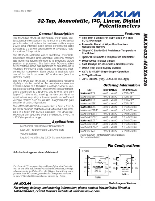
32-Tap, Nonvolatile, I2C, Linear, Digital Potentiometers MAX5432–MAX5435
ABSOLUTE MAXIMUM RATINGS
VDD to GND ...........................................................-0.3V to +6.0V SDA, SCL to GND..................................................-0.3V to +6.0V A0, H, L, and W to GND .............................-0.3V to (VDD + 0.3V) Maximum Continuous Current into H, L, and W MAX5432/MAX5434.....................................................±1.3mA MAX5433/MAX5435.....................................................±0.6mA Input/Output Latchup Immunity........................................±50mA Continuous Power Dissipation (TA = +70°C) 6-Pin Thin SOT23 (derate 9.1mW/°C above +70°C) ....727mW 8-Pin TDFN (derate 24.4mW/°C above +70°C) .........1951mW Operating Temperature Range ...........................-40°C to +85°C Junction Temperature ......................................................+150°C Storage Temperature Range .............................-60°C to +150°C Lead Temperature (soldering, 10s) .................................+300°C
MAX543双极性
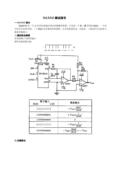
MAX543测试报告一.MAX543简介MAX543是一片12位的电流输出乘法的数模转换器。
它包括一个R—2R类型的DAC,一个串行转并行的寄存器,一个DAC寄存器和控制逻辑。
并且转换速率高,功耗低。
三线的串行总线易与微处理器接口。
二.测试的电路图该电路属于双级性输出硬件电路管脚分配三.功能特点四.引脚介绍五.工作时序1.2工作流程首先将LOAD端置高,SCLK,SRI清零,等待数据的输入。
当最高位到SRI时,把SCLK置高,数据被移入串转并寄存器(即脉冲的上升沿)。
再将SCLK 清零等待下一位数据。
重复12次,令LOAD 为低。
开始转换,相应的IOUT输出电流3.源程序用查表的方法,显示正弦波;12位串行DA,高八位存R1,低四位存R2中spi接口为p3.0,p3.1,p3.2clk equ p3.1sri equ p3.0load equ p3.2org 00hajmp startorg 30hstart:mov r7,#0;查表begin:acall init;初始化寄存器acall init_;初始化DAacall init_da;转换输出ajmp begininit:mov dptr,#tablemov a,r7movc a,@A+dptrmov r1,amov r2,#0ffhmov r3,#8mov r4,#4retinit_:setb load;初始化DAclr sriclr clkretinit_da:acall mobileacall delayacall _adretmobile:;将数据移入寄存器clr cloop:mov a,r1rlc amov sri,cmov r1,a;acall delaysetb clkacall delayclr clkacall delaydjnz r3,loopinc r7clr cloopl:mov a,r2rlc amov sri,cmov r2,a;acall delaysetb clkacall delayclr clkacall delaydjnz r4,looplret_ad:clr loadacall delayretdelay:mov r6,#10h;延时d1:djnz r6,d1retTABLE:DB 128, 131, 134, 137, 140, 144, 147, 150, 153, 156, 159, 162, 165, 168, 171, 174 DB 177, 180, 182, 185, 188, 191, 194, 196, 199, 201, 204, 206, 209, 211, 214, 216 DB 218, 220, 222, 224, 226, 228, 230, 232, 234, 236, 237, 239, 240, 242, 243, 244 DB 246, 247, 248, 249, 250, 251, 251, 252, 253, 253, 254, 254, 254, 255, 255, 255 DB 255, 255, 255, 254, 254, 254, 253, 253, 252, 252, 251, 250, 249, 248, 247, 246 DB 245, 244, 242, 241, 240, 238, 236, 235, 233, 231, 229, 227, 225, 223, 221, 219 DB 217, 215, 212, 210, 208, 205, 203, 200, 197, 195, 192, 189, 187, 184, 181, 178 DB 175, 172, 169, 167, 164, 160, 157, 154, 151, 148, 145, 142, 139, 136, 133, 130 DB 126, 123, 120, 117, 114, 111, 108, 105, 102, 99 , 96 , 92 , 89 , 87 , 84 , 81DB 78 , 75 , 72 , 69 , 67 , 64 , 61 , 59 , 56 , 53 , 51 , 48 , 46 , 44 , 41 , 39DB 37 , 35 , 33 , 31 , 29 , 27 , 25 , 23 , 21 , 20 , 18 , 16 , 15 , 14 , 12 , 11DB 10 , 9 , 8 , 7 , 6 , 5 , 4 , 4 , 3 , 3 , 2 , 2 , 1 , 1 , 1 , 0 DB 0 , 1 , 1 , 1 , 2 , 2 , 3 , 3 , 4 , 5 , 5 , 6 , 7 , 8 , 9 , 10 DB 12 , 13 , 14 , 16 , 17 , 19 , 20 , 22 , 24 , 26 , 28 , 30 , 32 , 34 , 36 , 38DB 40 , 42 , 45 , 47 , 50 , 52 , 55 , 57 , 60 , 62 , 65 , 68 , 71 , 74 , 76 , 79DB 82 , 85 , 88 , 91 , 94 , 97 , 100, 103, 106, 109, 112, 116, 119, 122, 125, 127 End。
max2器件中文手册

2N5432中文资料
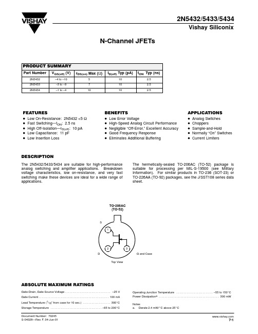
3
td(on)
ID = 25 mA
ID = 10 mA 2
Switching Time (ns)
1
tr
0
0
–2
–4
–6
–8
–10
VGS(off) – Gate-Source Cutoff Voltage (V)
Document Number: 70245 S-04028—Rev. F, 04-Jun-01
VGS(off) = –2 V
18
tf
VGS(off) = –8 V 12
6
td(off)
0 0
5
10
15
20
25
ID – Drain Current (mA)
7-3
元器件交易网
2N5432/5433/5434
Vishay Siliconix
Limits
2N5432
2N5433
2N5434
Parameter
Symbol
Test Conditions
Typa Min Max Min Max Min Max Unit
Static
Gate-Source Breakdown Voltage Gate-Source Cutoff Voltage Saturation Drain Currentb
TA = 150_C
VGS = 0 V, ID = 10 mA
IG = 1 mA , VDS = 0 V
–32 –25
–25
–25
V
–4 –10 –3
–9
–1
–4
150
100
30
mA
–5
–200
MAX5222中文资料完整

令中。
Figure 图 3.详细的串行接口时序图
数字输入 数字输入与 CMOS 逻辑兼容。当通过 0.3 ✕ VDD 和 0.7 ✕ VDD 之间的过渡区切换逻辑 输入时,电源电流稍微增加。 微处理器接口 MAX5222 串行接口与 Microwire、SPI 和 QSPI 兼容。对于 SPI,清除 CPOL 和 CPHA 位 (CPOL=0 和 CPHA=0)。cpol=0 将非活动时 钟状态设置为零,CPHA=0 更改 SCLK 下降沿 的数据。此设置允许 SPI 以全时钟速度运行。 如果您的祄 P 上没有串行端口,则可以使用 并行端口的 3 位逐位模拟串行端口操作。只 有在必要时才操作串行时钟,从而使电压输 出处的数字馈通最小化。
工作温度范围…………-40°C 至+85°C
接 地 的 所 有 其 他 插 脚 ( 注 1 ) -0.3V 至 结温…………………………………+150°C
(VDD+0.3V)
储存温度范围……………………-65°C 至
持续功耗(Ta=+70°C)
+150°C
8 针 SOT23(在+70°C 以上减额 8.7mW/° 铅温度(焊接 10s)……………………………
CIN
Note4
10
pF
动态性能
电压输出滑移速率 电压输出稳定时间 数字馈通 和串扰
电源电压范围 电源电流
关机电源电流
SR
CL = 100pF
1
To ± 1⁄2LSB, CL = 100pF
10
All 0s to all 1s
0.25
电源
VDD
2.7
5.5
ALL INPUTS=0 IDD
MAX532 资料 官方文档
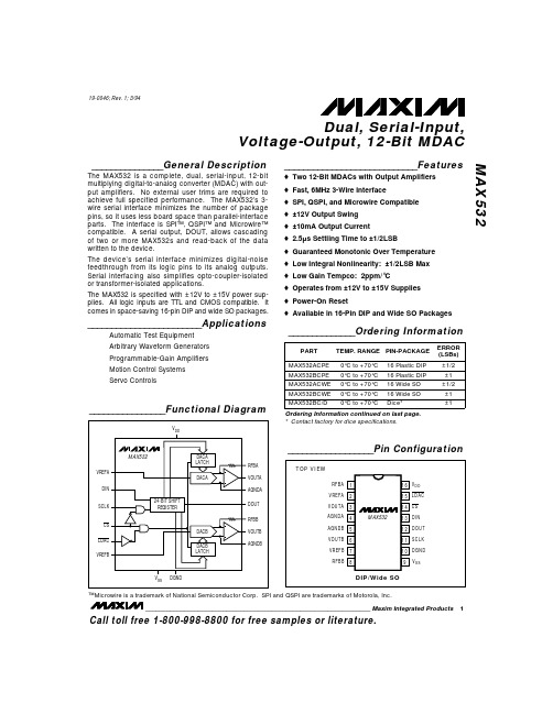
Call toll free 1-800-998-8800 for free samples or literature.
Dual, Serial-Input, Voltage-Output, 12-Bit MDAC MAX532
ABSOLUTE MAXIMUM RATINGS
Pin Voltages VDD to DGND, AGNDA, AGNDB........................-0.3V to +17V VSS to DGND, AGNDA, AGNDB (Note 1) ..........+0.3V to -17V VREFA, VREFB.............................(VSS - 0.3V) to (VDD + 0.3V) AGNDA, AGNDB .....................(DGND - 0.3V) to (VDD + 0.3V) VOUTA, VOUTB ...........................(VSS - 0.3V) to (VDD + 0.3V) RFBA, RFBB.................................(VSS - 0.3V) to (VDD + 0.3V) SCLK, DIN, DOUT, LDAC, CS ..(DGND - 0.3V) to (VDD + 0.3V) DOUT Sink Current .............................................................20mA Continuous Power Dissipation (TA = +70°C) Plastic DIP (derate 10.53mW/°C above +70°C) ..........842mW Wide SO (derate 9.52mW/°C above +70°C)................762mW CERDIP (derate 10.00mW/°C above +70°C) ...............800mW Operating Temperature Ranges: MAX532_C__ ......................................................0°C to +70°C MAX532_E__....................................................-40°C to +85°C MAX532_MJE ................................................-55°C to +125°C Junction Temperatures: MAX532_C__, E__........................................................+150°C MAX532_MJE...............................................................+175°C Storage Temperature Range ........................... -65°C to +160°C Lead Temperature (soldering, 10sec) ........................... +300°C
MAX5432_07中文资料

Operating Temperature Range ...........................-40°C to +85°C Junction Temperature ......................................................+150°C Storage Temperature Range .............................-60°C to +150°C Lead Temperature (soldering, 10s) .................................+300°C
The MAX5432–MAX5435 feature an internal, nonvolatile, electrically erasable programmable read-only memory (EEPROM) that returns the wiper to its previously stored position at power-up. The fast-mode I2C-compatible serial interface allows communication at data rates up to 400kbps, minimizing board space and reducing interconnection complexity. Each device is available with multiple factory-preset I2C addresses (see the Ordering Information/Selector Guide).
数字电位器max5402中文资料
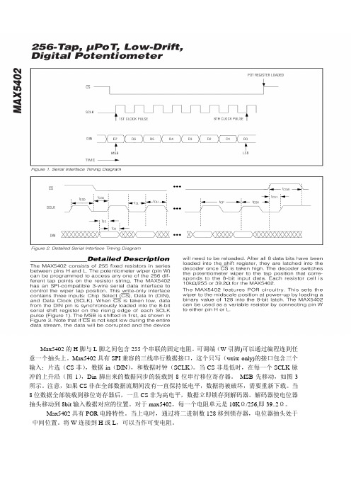
Max5402的H脚与L脚之间包含255个串联的固定电阻。
可调端(W引脚)可以通过编程连到任意一个抽头上。
Max5402具有SPI兼容的三线串行数据接口,这个只写(write-only)的接口包含三个输入:片选(CS非),数据in(DIN),和数据时钟(SCLK)。
当CS非是低时,在每一个SCLK脉冲的上升沿(图1),Din脚出来的数据同步的装载到8位串行移位寄存器。
MSB先移动,如图3所示。
注意,如果CS非在全部数据流期间没有一直保持低电平,数据将被破坏,需要重新下载。
当8位数据全部装载到移位寄存器后,一旦CS非为高电平,数据立即锁存到解码器。
解码器使电位器抽头移动到8bit输入数据对应的位置。
对于max5402,每一个电阻单元是10KΩ/256,即39..2Ω。
Max5402具有POR电路特性。
当上电时,通过将二进制数128移到锁存器,电位器抽头处于
中间位置。
将W连接到H或L,可以当作可变电阻。
MAX5436中文资料

TSSOP
________________________________________________________________ Maxim Integrated Products
1
For pricing, delivery, and ordering information, please contact Maxim/Dallas Direct! at 1-888-629-4642, or visit Maxim’s website at .
MAX5436–MAX5439
Ordering Information
PART MAX5436EUB TEMP RANGE PINPACKAGE RESISTANCE (kΩ) 50 50 100 100
-40°C to +85°C 10 µMAX 40°C to +85°C 14 TSSOP -40°C to +85°C 10 µMAX -40°C to +85°C 14 TSSOP
元器件交易网
±15V, 128-Tap, Low-Drift Digital Potentiometers MAX5436–MAX5439
ABSOLUTE MAXIMUM RATINGS
VDD to GND, VSS = GND........................................-0.3V to +34V VSS to GND, VDD = GND........................................-34V to +0.3V VDD to VSS ..............................................................-0.3V to +34V VDD to VCC ........................................................-6.3V to +28.75V VCC to VSS ..............................................................-0.3V to +34V VCC to GND ..............................................................-0.3V to +6V DIN, SCLK, CS, SHDN ...............................-0.3V to (VCC + 0.3V) H, L, W, IN+, IN-, OUT .....................(VSS - 0.3V) to (VDD + 0.3V) Maximum Continuous Current into H, L, and W MAX5436–MAX5439.......................................................±1mA Continuous Power Dissipation (TA = +70°C) 10-Pin µMAX (derate 6.94mW/°C above +70°C) .........556mW 14-Pin TSSOP (derate 9.1mW/°C above +70°C) .........727mW Operating Temperature Range ...........................-40°C to +85°C Junction Temperature ......................................................+150°C Storage Temperature Range .............................-65°C to +150°C Lead Temperature (soldering, 10s) .................................+300°C
MAX5431AEUB+中文资料
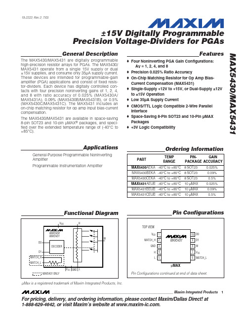
MAX5430 toc06
DIVIDER RATIO ACCURACY (%)
±15V Digitally Programmable Precision Voltage-Dividers for PGAs
Typical Operating Characteristics
(VDD = +15V, VSS = -15V or VSS = GND, VH = 5V, VL =-5V, TA = 25°C, unless otherwise noted.) (Note 3)
CIN
5
pF
POWER REQUIREMENTS
Negative Supply CurrentµA
Positive Supply Current
IDD
35
60
µA
Positive Power-Supply Voltage
VDD
Negative Power-Supply Voltage
VSS
10.8 -15.75
15.75
V
0
V
DYNAMIC PERFORMANCE
Switching Time
tD2W, tH2W
0.3
µs
Note 1: All devices are 100% production tested at TA = +25°C. SOT23 packages are guaranteed by design from TA = TMIN to TMAX. Note 2: Gain accuracy is measured without load at pin W.
Features
♦ Four Noninverting PGA Gain Configurations: AV = 1, 2, 4, and 8
MAX232中文资料(官方版)
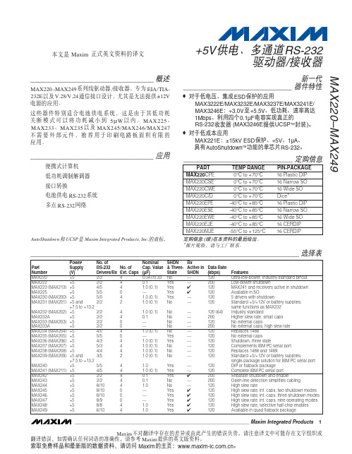
________________________________ 应用
便携式计算机 低功耗调制解调器 接口转换 电池供电 RS-232 系统 多点 RS-232 网络
_____________________________ 定购信息
PART MAX220CPE MAX220CSE MAX220CWE MAX220C/D MAX220EPE MAX220ESE MAX220EWE MAX220EJE MAX220MJE TEMP RANGE 0°C to +70°C 0°C to +70°C 0°C to +70°C 0°C to +70°C -40°C to +85°C -40°C to +85°C -40°C to +85°C -40°C to +85°C -55°C to +125°C PIN-PACKAGE 16 Plastic DIP 16 Narrow SO 16 Wide SO Dice* 16 Plastic DIP 16 Narrow SO 16 Wide SO 16 CERDIP 16 CERDIP
索取免费样品和最新版的数据资料,请访问 Maxim 的主页:。
+5V 供电、多通道 RS-232 驱动器/接收器 MAX220–MAX249
ABSOLUTE MAXIMUM RATINGS—MAX220/222/232A/233A/242/243
Supply Voltage (VCC) ...............................................-0.3V to +6V V+ (Note 1) ..................................................(VCC - 0.3V) to +14V V- (Note 1) .............................................................+0.3V to +14V Input Voltages TIN..............................................................-0.3V to (VCC - 0.3V) RIN (Except MAX220) ........................................................±30V RIN (MAX220).....................................................................±25V TOUT (Except MAX220) (Note 2) .......................................±15V TOUT (MAX220)...............................................................±13.2V Output Voltages TOUT ...................................................................................±15V ROUT .........................................................-0.3V to (VCC + 0.3V) Driver/Receiver Output Short Circuited to GND.........Continuous Continuous Power Dissipation (TA = +70°C) 16-Pin Plastic DIP (derate 10.53mW/°C above +70°C) .842mW 18-Pin Plastic DIP (derate 11.11mW/°C above +70°C)..889mW 20-Pin Plastic DIP (derate 8.00mW/°C above +70°C) ..440mW 16-Pin Narrow SO (derate 8.70mW/°C above +70°C) ...696mW 16-Pin Wide SO (derate 9.52mW/°C above +70°C)......762mW 18-Pin Wide SO (derate 9.52mW/°C above +70°C)......762mW 20-Pin Wide SO (derate 10.00mW/°C above +70°C)....800mW 20-Pin SSOP (derate 8.00mW/°C above +70°C) ..........640mW 16-Pin CERDIP (derate 10.00mW/°C above +70°C).....800mW 18-Pin CERDIP (derate 10.53mW/°C above +70°C).....842mW Operating Temperature Ranges MAX2_ _AC_ _, MAX2_ _C_ _ .............................0°C to +70°C MAX2_ _AE_ _, MAX2_ _E_ _ ..........................-40°C to +85°C MAX2_ _AM_ _, MAX2_ _M_ _ .......................-55°C to +125°C Storage Temperature Range .............................-65°C to +160°C Lead Temperature (soldering, 10s) (Note 3) ...................+300°C
MAX5842MEUB+中文资料
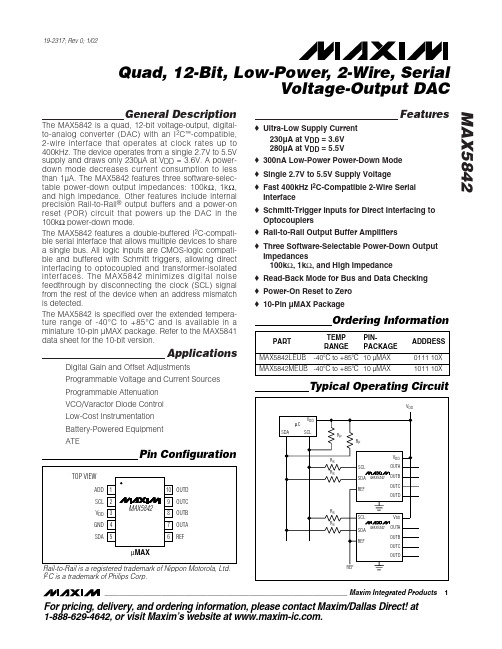
General DescriptionThe MAX5842 is a quad, 12-bit voltage-output, digital-to-analog converter (DAC) with an I 2C ™-compatible, 2-wire interface that operates at clock rates up to 400kHz. The device operates from a single 2.7V to 5.5V supply and draws only 230µA at V DD = 3.6V. A power-down mode decreases current consumption to less than 1µA. The MAX5842 features three software-selec-table power-down output impedances: 100k Ω, 1k Ω,and high impedance. Other features include internal precision Rail-to-Rail ®output buffers and a power-on reset (POR) circuit that powers up the DAC in the 100k Ωpower-down mode.The MAX5842 features a double-buffered I 2C-compati-ble serial interface that allows multiple devices to share a single bus. All logic inputs are CMOS-logic compati-ble and buffered with Schmitt triggers, allowing direct interfacing to optocoupled and transformer-isolated interfaces. The MAX5842 minimizes digital noise feedthrough by disconnecting the clock (SCL) signal from the rest of the device when an address mismatch is detected.The MAX5842 is specified over the extended tempera-ture range of -40°C to +85°C and is available in a miniature 10-pin µMAX package. Refer to the MAX5841data sheet for the 10-bit version.ApplicationsDigital Gain and Offset Adjustments Programmable Voltage and Current Sources Programmable Attenuation VCO/Varactor Diode Control Low-Cost Instrumentation Battery-Powered Equipment ATEFeatureso Ultra-Low Supply Current230µA at V DD = 3.6V 280µA at V DD = 5.5Vo 300nA Low-Power Power-Down Mode o Single 2.7V to 5.5V Supply Voltage o Fast 400kHz I 2C-Compatible 2-Wire Serial Interface o Schmitt-Trigger Inputs for Direct Interfacing to Optocouplers o Rail-to-Rail Output Buffer Amplifierso Three Software-Selectable Power-Down Output Impedances100k Ω, 1k Ω, and High Impedance o Read-Back Mode for Bus and Data Checking o Power-On Reset to Zero o 10-Pin µMAX PackageMAX5842Quad, 12-Bit, Low-Power, 2-Wire, SerialVoltage-Output DAC________________________________________________________________Maxim Integrated Products 1Pin ConfigurationOrdering InformationTypical Operating Circuit19-2317; Rev 0; 1/02For pricing, delivery, and ordering information,please contact Maxim/Dallas Direct!at 1-888-629-4642, or visit Maxim’s website at .Rail-to-Rail is a registered trademark of Nippon Motorola, Ltd.I 2C is a trademark of Philips Corp.M A X 5842Quad, 12-Bit, Low-Power, 2-Wire, Serial Voltage-Output DAC 2_______________________________________________________________________________________ABSOLUTE MAXIMUM RATINGSELECTRICAL CHARACTERISTICS(V DD = +2.7V to +5.5V, GND = 0, V REF = V DD , R L = 5k Ω, C L = 200pF, T A = T MIN to T MAX , unless otherwise noted. Typical values areStresses beyond those listed under “Absolute Maximum Ratings” may cause permanent damage to the device. These are stress ratings only, and functional operation of the device at these or any other conditions beyond those indicated in the operational sections of the specifications is not implied. Exposure to absolute maximum rating conditions for extended periods may affect device reliability.V DD , SCL, SDA to GND............................................-0.3V to +6V OUT_, REF, ADD to GND..............................-0.3V to V DD + 0.3V Maximum Current into Any Pin............................................50mA Continuous Power Dissipation (T A = +70°C)10-Pin µMAX (derate 5.6mW above +70°C).................444mWOperating Temperature Range ...........................-40°C to +85°C Storage Temperature Range.............................-65°C to +150°C Maximum Junction Temperature.....................................+150°C Lead Temperature (soldering, 10s).................................+300°CMAX5842Quad, 12-Bit, Low-Power, 2-Wire, SerialVoltage-Output DAC_______________________________________________________________________________________3ELECTRICAL CHARACTERISTICS (continued)M A X 5842Quad, 12-Bit, Low-Power, 2-Wire, Serial Voltage-Output DAC 4_______________________________________________________________________________________INTEGRAL NONLINEARITYvs. INPUT CODEM A X 5842 t o c 01INPUT CODEI N L (L S B )307220481024-3-2-101234-44096INTEGRAL NONLINEARITY vs. SUPPLY VOLTAGEM A X 5842 t o c 02SUPPLY VOLTAGE (V)I N L (L S B )4.84.13.41234502.75.5INTEGRAL NONLINEARITY vs. TEMPERATUREM A X 5842 t o c 03TEMPERATURE (°C)I N L (L S B )603510-15123450-4085DIFFERENTIAL NONLINEARITYvs. INPUT CODEM A X 5842 t o c 04INPUT CODED N L (L S B )307220481024-0.75-0.50-0.2500.250.500.751.00-1.004096DIFFERENTIAL NONLINEARITYvs. SUPPLY VOLTAGEM A X 5842 t o c 05SUPPLY VOLTAGE (V)D N L (L S B )4.84.13.4-1.00-0.75-0.50-0.2502.7 5.5DIFFERENTIAL NONLINEARITYvs. TEMPERATUREM A X 5842 t o c 06TEMPERATURE (°C)D N L (L S B )603510-15-0.75-0.50-0.25-1.00-4085Typical Operating Characteristics(V DD = +5V, R L = 5k Ω.)ELECTRICAL CHARACTERISTICS (continued)(V DD = +2.7V to +5.5V, GND = 0, V REF = V DD , R L = 5k Ω, C L = 200pF, T A = T MINto T MAX , unless otherwise noted. Typical values are at V = +5V, T = +25°C.) (Note 1)Note 1:All devices are 100% production tested at T A = +25°C and are guaranteed by design for T A = T MIN to T MAX .Note 2:Static specifications are tested with the output unloaded.Note 3:Linearity is guaranteed from codes 115 to 3981.Note 4:Offset and gain error limit the FSR.Note 5:Guaranteed by design. Not production tested.MAX5842Quad, 12-Bit, Low-Power, 2-Wire, SerialVoltage-Output DAC_______________________________________________________________________________________5ZERO-CODE ERROR vs. SUPPLY VOLTAGEM A X 5842 t o c 07SUPPLY VOLTAGE (V)Z E R O -C O D E E R R O R (m V )4.84.13.424681002.75.5NO LOADZERO-CODE ERROR vs. TEMPERATUREM A X 5842 t o c 08TEMPERATURE (°C)Z E R O -C O D E E R R O R (m V )603510-152468100-4085NO LOADGAIN ERROR vs. SUPPLY VOLTAGEM A X 5842 t o c 09SUPPLY VOLTAGE (V)G A I N E R R O R (%F S R )4.84.13.4-0.4-0.8-1.2-1.6-2.02.75.5NO LOADGAIN ERROR vs. TEMPERATUREM A X 5842 t o c 10TEMPERATURE (°C)G A I N E R R O R (%F S R )603510-15-0.4-0.8-1.2-1.6-2.00-4085NO LOADDAC OUTPUT VOLTAGEvs. OUTPUT SOURCE CURRENT (NOTE 6)OUTPUT SOURCE CURRENT (mA)D A C O U T P U T V O L T A GE (V )8642123456010DAC OUTPUT VOLTAGEvs. OUTPUT SINK CURRENT (NOTE 6)OUTPUT SINK CURRENT (mA)D A C O U T P U T V O L T A GE (V )86420.51.01.52.02.510SUPPLY CURRENT vs. INPUT CODEM A X 5842 t o c 13INPUT CODES U P P L Y C U R R E N T (µA )3276245716388192602803003202404096SUPPLY CURRENT vs. SUPPLY VOLTAGESUPPLY VOLTAGE (V)S U P P L Y C U R R E N T (µA )4.84.13.42602803003202402.7 5.5Typical Operating Characteristics (continued)(V DD = +5V, R L = 5k Ω.)M A X 5842Quad, 12-Bit, Low-Power, 2-Wire, Serial Voltage-Output DAC 6_______________________________________________________________________________________POWER-DOWN SUPPLY CURRENTvs. SUPPLY VOLTAGESUPPLY VOLTAGE (V)P O W E R -D O W N S U P P L YC U R R E N T (nA )4.84.13.41002003004005000 2.75.5POWER-UP GLITCHMAX5842 toc17100µs/divV DDOUT_5V10mV/divEXITING SHUTDOWN2µs/divOUT_500mV/divC LOAD = 200pF CODE = 800 hexMAJOR CARRY TRANSITION(POSITIVE)2µs/divOUT_5mV/divMAJOR CARRY TRANSITION(NEGATIVE)MAX5842 toc202µs/divOUT_5mV/div C LOAD = 200pFR L = 5k ΩCODE = 800 hex TO 7FF hex Typical Operating Characteristics (continued)(V DD = +5V, R L = 5k Ω.)SETTLING TIME (POSITIVE)2µs/divOUT_500mV/divC LOAD = 200pFCODE = 400 hex TO C00 hexMAX5842Quad, 12-Bit, Low-Power, 2-Wire, SerialVoltage-Output DAC_______________________________________________________________________________________7SETTLING TIME (NEGATIVE)2µs/divOUT_500mV/divC LOAD = 200pFCODE = C00 hex TO 400 hex DIGITAL FEEDTHROUGH40µs/divOUT_2mV/divC LOAD = 200pF f SCL = 12kHz CODE = 000 hexSCL 2V/divCROSSTALKMAX5842 toc244µs/divV OUTB1mV/divV OUTA 2V/divTypical Operating Characteristics (continued)(V DD = +5V, R L = 5k Ω.)Note 6:The ability to drive loads less than 5k Ωis not implied.M A X 5842Quad, 12-Bit, Low-Power, 2-Wire, Serial Voltage-Output DAC 8_______________________________________________________________________________________Detailed DescriptionThe MAX5842 is a quad, 12-bit, voltage-output DAC with an I 2C/SMBus-compatible 2-wire interface. The device consists of a serial interface, power-down cir-cuitry, four input and DAC registers, four 12-bit resistor string DACs, four unity-gain output buffers, and output resistor networks. The serial interface decodes the address and control bits, routing the data to the proper input or DAC register. Data can be directly written to the DAC register, immediately updating the device out-put, or can be written to the input register without changing the DAC output. Both registers retain data as long as the device is powered.DAC OperationThe MAX5842 uses a segmented resistor string DAC architecture, which saves power in the overall system and guarantees output monotonicity. The MAX5842’s input coding is straight binary, with the output voltage given by the following equation:where N = 12 (bits), and D = the decimal value of the input code (0 to 4095).Output BufferThe MAX5842 analog outputs are buffered by preci-sion, unity-gain followers that slew 0.5V/µs. Each buffer output swings rail-to-rail, and is capable of driving 5k Ωin parallel with 200pF. The output settles to ±0.5LSB within 4µs.Power-On ResetThe MAX5842 features an internal POR circuit that ini-tializes the device upon power-up. The DAC registersare set to zero scale and the device is powered down,with the output buffers disabled and the outputs pulled to GND through the 100k Ωtermination resistor.Following power-up, a wake-up command must be initi-ated before any conversions are performed.Power-Down ModesThe MAX5842 has three software-controlled, low-power, power-down modes. All three modes disable the output buffers and disconnect the DAC resistor strings from REF, reducing supply current draw to 1µA and the reference current draw to less than 1µA. I n power-down mode 0, the device output is high imped-ance. I n power-down mode 1, the device output is internally pulled to GND by a 1k Ωtermination resistor.I n power-down mode 2, the device output is internally pulled to GND by a 100k Ωtermination resistor. Table 1shows the power-down mode command words.Upon wake-up, the DAC output is restored to its previ-ous value. Data is retained in the input and DAC regis-ters during power-down mode.Digital InterfaceThe MAX5842 features an I 2C/SMBus-compatible 2-wire interface consisting of a serial data line (SDA)and a serial clock line (SCL). The MAX5842 is SMBus compatible within the range of V DD = 2.7V to 3.6V. SDA and SCL facilitate bidirectional communication between the MAX5842 and the master at rates up to 400kHz.Figure 1 shows the 2-wire interface timing diagram. The MAX5842 is a transmit/receive slave-only device, rely-ing upon a master to generate a clock signal. The mas-ter (typically a microcontroller) initiates data transfer on the bus and generates SCL to permit that transfer.A master device communicates to the MAX5842 by transmitting the proper address followed by commandand/or data words. Each transmit sequence is framedMAX5842Quad, 12-Bit, Low-Power, 2-Wire, SerialVoltage-Output DAC_______________________________________________________________________________________9by a START (S) or REPEATED START (S r ) condition and a STOP (P) condition. Each word transmitted over the bus is 8 bits long and is always followed by an acknowledge clock pulse.The MAX5842 SDA and SCL drivers are open-drain outputs, requiring a pullup resistor to generate a logic high voltage (see Typical Operating Circuit). Series resistors R S are optional. These series resistors protect the input stages of the MAX5842 from high-voltage spikes on the bus lines, and minimize crosstalk and undershoot of the bus signals.Bit TransferOne data bit is transferred during each SCL clock cycle. The data on SDA must remain stable during the high period of the SCL clock pulse. Changes in SDA while SCL is high are control signals (see STAR T andSTOP Conditions). Both SDA and SCL idle high when the I 2C bus is not busy.START and STOP ConditionsWhen the serial interface is inactive, SDA and SCL idle high. A master device initiates communication by issu-ing a START condition. A START condition is a high-to-low transition on SDA with SCL high. A STOP condition is a low-to-high transition on SDA, while SCL is high (Figure 2). A START condition from the master signals the beginning of a transmission to the MAX5842. The master terminates transmission by issuing a not acknowledge followed by a STOP condition (see Acknowledge Bit (ACK )). The STOP condition frees the bus. I f a repeated START condition (Sr) is generated instead of a STOP condition, the bus remains active.When a STOP condition or incorrect address is detect-ed, the MAX5842 internally disconnects SCL from the serial interface until the next START condition, minimiz-ing digital noise and feedthrough.Early STOP ConditionsThe MAX5842 recognizes a STOP condition at any point during transmission except if a STOP condition occurs in the same high pulse as a START condition (Figure 3). This condition is not a legal I 2C format; at least one clock pulse must separate any START and STOP conditions.Repeated START ConditionsA REPEATED START (S r ) condition may indicate a change of data direction on the bus. Such a change occurs when a command word is required to initiate a read operation. S r may also be used when the bus master is writing to several I 2C devices and does not want to relinquish control of the bus. The MAX5842 ser-ial interface supports continuous write operations with or without an S r condition separating them. ContinuousM A X 5842Quad, 12-Bit, Low-Power, 2-Wire, Serial Voltage-Output DAC 10read operations require S r conditions because of the change in direction of data flow.Acknowledge Bit (ACK)The acknowledge bit (ACK) is the ninth bit attached to any 8-bit data word. ACK is always generated by the receiving device. The MAX5842 generates an ACK when receiving an address or data by pulling SDA low during the ninth clock period. When transmitting data,the MAX5842 waits for the receiving device to generate an ACK. Monitoring ACK allows for detection of unsuc-cessful data transfers. An unsuccessful data transfer occurs if a receiving device is busy or if a system fault has occurred. I n the event of an unsuccessful data transfer, the bus master should reattempt communica-tion at a later time.Slave AddressA bus master initiates communication with a slave device by issuing a START condition followed by the 7-bit slave address (Figure 4). When idle, the MAX5842waits for a START condition followed by its slaveaddress. The serial interface compares each address value bit by bit, allowing the interface to power down immediately if an incorrect address is detected. The LSB of the address word is the Read/Write (R/W ) bit.R/W indicates whether the master is writing to or read-ing from the MAX5842 (R/W = 0 selects the write condi-tion, R/W = 1 selects the read condition). After receiving the proper address, the MAX5842 issues anACK by pulling SDA low for one clock cycle.The MAX5842 has four different factory/user-pro-grammed addresses (Table 2). Address bits A6through A1 are preset, while A0 is controlled by ADD.Connecting ADD to GND sets A0 = 0. Connecting ADD to V DD sets A0 = 1. This feature allows up to four MAX5842s to share the same bus.Write Data FormatIn write mode (R/W = 0), data that follows the address byte controls the MAX5842 (Figure 5). Bits C3-C0 con-figure the MAX5842 (Table 3). Bits D11-D0 are DAC data. I nput and DAC registers update on the falling edge of SCL during the acknowledge bit. Should the write cycle be prematurely aborted, data is not updated and the write cycle must be repeated. Figure 6 shows two example write data sequences.Extended Command ModeThe MAX5842 features an extended command mode that is accessed by setting C3-C0 = 1 and D11-D8 = 0.The next data byte writes to the shutdown registers (Figure 7). Setting bits A, B, C, or D to 1 sets that DACFigure 2. START and STOP ConditionsFigure 3. Early STOP ConditionsMAX5842Quad, 12-Bit, Low-Power, 2-Wire, SerialVoltage-Output DAC______________________________________________________________________________________11to the selected power-down mode based on the states of PD0 and PD1 (Table 1). Any combination of the four DACs can be controlled with a single write sequence.Read Data FormatIn read mode (R/W = 1), the MAX5842 writes the con-tents of the DAC register to the bus. The direction of data flow reverses following the address acknowledge by the MAX5842. The device transmits the first byte of data, waits for the master to acknowledge, then trans-mits the second byte. Figure 8 shows an example read data sequence.I 2C CompatibilityThe MAX5842 is compatible with existing I 2C systems.SCL and SDA are high-impedance inputs; SDA has an open drain that pulls the data line low during the ninth clock pulse. The Typical Operating Circuit shows a typ-ical I 2C application. The communication protocol sup-ports the standard I 2C 8-bit communications. The general call address is ignored. The MAX5842 address is compatible with the 7-bit I 2C addressing protocol only. No 10-bit address formats are supported.Digital Feedthrough SuppressionWhen the MAX5842 detects an address mismatch, the serial interface disconnects the SCL signal from the core circuitry. This minimizes digital feedthrough caused by the SCL signal on a static output. The serial interface reconnects the SCL signal once a valid START condition is detected.Applications InformationDigital Inputs and Interface LogicThe MAX5842 2-wire digital interface is I 2C/SMBus compatible. The two digital inputs (SCL and SDA) load the digital input serially into the DAC. Schmitt-trigger buffered inputs allow slow-transition interfaces such as optocouplers to interface directly to the device. The digital inputs are compatible with CMOS logic levels.Power-Supply Bypassing andGround ManagementCareful PC board layout is important for optimal system performance. Keep analog and digital signals separate to reduce noise injection and digital feedthrough. Use a ground plane to ensure that the ground return from GND to the power-supply ground is short and low impedance. Bypass V DD with a 0.1µF capacitor to ground as close to the device as possible.Chip InformationTRANSISTOR COUNT: 17,213PROCESS: BiCMOSFigure 6. Example Write Command SequencesM A X 5842Quad, 12-Bit, Low-Power, 2-Wire, Serial Voltage-Output DAC 12______________________________________________________________________________________MAX5842Quad, 12-Bit, Low-Power, 2-Wire, SerialVoltage-Output DAC______________________________________________________________________________________13Table 3. Command Byte Definitions (continued)Figure 8. Example Read Word Data SequenceM A X 5842Quad, 12-Bit, Low-Power, 2-Wire, Serial Voltage-Output DAC 14______________________________________________________________________________________Functional DiagramMAX5842Quad, 12-Bit, Low-Power, 2-Wire, SerialVoltage-Output DACMaxim cannot assume responsibility for use of any circuitry other than circuitry entirely embodied in a Maxim product. No circuit patent licenses are implied. Maxim reserves the right to change the circuitry and specifications without notice at any time.Maxim Integrated Products, 120 San Gabriel Drive, Sunnyvale, CA 94086 408-737-7600 ____________________15©2002 Maxim Integrated ProductsPrinted USAis a registered trademark of Maxim Integrated Products.Package Information。
YAV MAX PRO无线多功能采集卡技术手册WIFI8572 ZIGBEE8572 BT8572

YAV MAX PRO无线多功能采集卡技术手册V1801武汉亚为电子科技有限公司WIFI8572ZIGBEE8572BT8572关于本手册为亚为推出的YA V MAX PRO数据采集卡的用户手册,主要内容包括功能概述、12路模拟量输入功能、4路数字量输入、2路PWM输出、2路模拟量输出、应用实例、性能测试、注意事项及故障排除等。
说明序号版本号编写人编写日期支持对象应用时间特别说明1 1.0郑先科2014.05YA V MAX PRO采集卡2 2.0郑先科2016.01YA V MAX PRO采集卡3 3.0郑先科2017.01YA V MAX PRO采集卡2017.01适用于RS232\485\WiFi\GPRS ZIGBEE\蓝牙\433M无线4 4.0李雪2017.08YA V MAX PRO采集卡2017.08目录0.快速上手 (1)产品包装内容 (1)应用软件 (1)接口定义 (1)⏹端子排列 (1)⏹端子描述 (2)通信 (3)1.产品概述 (3)技术指标 (3)⏹模拟信号输入 (4)⏹数字信号输入 (5)⏹数字信号输出 (5)⏹模拟信号输出 (6)⏹PWM输入 (6)⏹PWM输出 (6)⏹通信总线 (6)⏹温度参数 (6)硬件特点 (7)原理框图 (7)2.采集卡信号接线 (9)AI模拟量接线 (9)DI数字量接线 (9)DO数字量接线 (10)3.模拟量输入功能 (11)模拟量输入 (11)输入采样原理 (11)输入接线 (11)采样值计算 (13)⏹无符号整型 (13)⏹ADC数据类型 (13)⏹模拟量值 (13)4.模拟量输出功能 (14)输出原理 (14)5.数字量输入功能 (14)数字输入原理 (14)DI高低电平/无源触点输入 (15)计数功能输入 (15)测频功能输入 (15)PWM功能输入 (16)编码器输入 (16)AO输出匹配输入 (16)输入接线方式 (16)6.数字量输出功能 (17)输出原理 (17)DO高低电平输出 (18)输出接线方式 (18)PWM输出 (19)7.通信协议 (19)亚为WSN无线模块IOT通信协议 (19)8.应用实例 (22)软件应用 (22)⏹组态及PLC (23)⏹WSN无线通信 (24)9.注意事项及故障排除 (25)注意事项 (25)⏹存储说明 (25)⏹出货清单 (25)⏹质保及售后 (25)⏹特别说明 (25)故障排除 (26)⏹无法正常连接至上位机 (26)⏹VI文件打不开 (27)⏹数值不正常 (27)⏹DI测频计数没反应 (27)⏹多卡数据相同 (28)⏹采集速度不够 (28)⏹软件出现错误 (28)10.性能测试 (28)安全规范 (28)耐电压范围测试 (29)环境适应性测试 (29)11.文档权利及免责声明 (30)12.联系方式.......................................................................................................................错误!未定义书签。
R5432V规格书中文版

VDET2n+0.2V~0.7V 100mV 步进(VREL2n)
(n=1、2、3、4、5)
均衡检测电圧
3.45V~4.45V 0.005V 步进(VCBDn)
(n=1、2、3、4、5)
均衡解除电圧
CBDETn-0.0V~0.4V 50mV 步进(VCBR1n)
(n=1、2、3、4、5)
●延迟时间设定・・・・・・・・・・・・・・・・・・・ 过充电检测延迟时间
-3-
R5432VxxxXX
*1:n=1、2、3、4、5
-4-
R5432VxxxXX ■引脚排列图
SSOP-24 24 23 22 21 20 19 18 17 16 15 14 13
Mark Side
■引脚说明
1 2 3 4 5 6 7 8 9 10 11 12
编号 1 2 3 4 5 6 7 8 9 10 11 12 13 14 15 16 17 18 19 20 21 22 23 24
放电 过电流
检测 电压 1 VDET31
(V) 0.200 0.100 0.200 0.100 0.300 0.200 0.200 0.200 0.100 0.200 0.200 0.100
放电 过电流
检测 电压 2 VDET32
(V) 0.600 0.600 0.600 0.600 0.600 0.450 0.450 0.600 0.250 0.600 0.600 0.450
●功能序号一览 型号
R5432VxxxXA
过充电保护 解除方法
电平解除
过放电保护 解除方法
电平解除
向 0V 电池 充电可否
可
断线检测 可/不可
可
级联 可/不可
- 1、下载文档前请自行甄别文档内容的完整性,平台不提供额外的编辑、内容补充、找答案等附加服务。
- 2、"仅部分预览"的文档,不可在线预览部分如存在完整性等问题,可反馈申请退款(可完整预览的文档不适用该条件!)。
- 3、如文档侵犯您的权益,请联系客服反馈,我们会尽快为您处理(人工客服工作时间:9:00-18:30)。
Stresses beyond those listed under “Absolute Maximum Ratings” may cause permanent damage to the device. These are stress ratings only, and functional operation of the device at these or any other conditions beyond those indicated in the operational sections of the specifications is not implied. Exposure to absolute maximum rating conditions for extended periods may affect device reliability.
*Future product—contact factory for availability. **EP = Exposed pad.
Selector Guide appears at end of data sheet.
TOP VIEW
Pin Configurations
†Purchase of I2C components from Maxim Integrated Products,
Applications
Mechanical Potentiometer Replacement
Low-Drift Programmable-Gain Amplifiers
Volume Control
Liquid-Crystal Display (LCD) Screen Adjustment
Features
The MAX5432/MAX5433 are available in a 3mm x 3mm 8pin TDFN package and the MAX5434/MAX5435 are available in a 6-pin thin SOT23 package. The MAX5432– MAX5435 are specified over the extended (-40°C to +85°C) temperature range.
Ordering Information
PART MAX5432LETA MAX5432META* MAX5433LETA MAX5433META* MAX5434LEZT-T MAX5434MEZT-T* MAX5434NEZT-T* MAX5434PEZT-T* MAX5435LEZT-T MAX5435MEZT-T* MAX5435NEZT-T* MAX5435PEZT-T*
Operating Temperature Range ...........................-40°C to +85°C Junction Temperature ......................................................+150°C Storage Temperature Range .............................-60°C to +150°C Lead Temperature (soldering, 10s) .................................+300°C
♦ 5ppm/°C Ratiometric Temperature Coefficient ♦ 50kΩ/100kΩ Resistor Values ♦ Fast 400kbps I2C-Compatible Serial Interface ♦ 500nA (typ) Static Supply Current ♦ +2.7V to +5.25V Single-Supply Operation ♦ 32 Tap Positions ♦ ±0.15 LSB INL (typ), ±0.15 LSB DNL (typ)
ELECTRICAL CHARACTERISTICS
(VDD = +2.7V to +5.25V, VH = VDD, VL = GND, TA = -40°C to +85°C, unless otherwise noted. Typical values are at VDD = +5V, TA = +25°C.) (Note 1)
MAX5432–MAX5435
32-Tap, Nonvolatile, I2C, Linear, Digital Potentiometers
ABSOLUTE MAXIMUM RATINGS
VDD to GND ...........................................................-0.3V to +6.0V SDA, SCL to GND..................................................-0.3V to +6.0V A0, H, L, and W to GND .............................-0.3V to (VDD + 0.3V) Maximum Continuous Current into H, L, and W
♦ Tiny 3mm x 3mm 8-Pin TDFN and 6-Pin Thin SOT23 Packages
♦ Power-On Recall of Wiper Position from Nonvolatile Memory
♦ 35ppm/°C End-to-End Resistance Temperature Coefficient
PIN-PACKAGE 8 TDFN-EP** 8 TDFN-EP** 8 TDFN-EP** 8 TDFN-EP** 6 Thin SOT23-6 6 Thin SOT23-6 6 Thin SOT23-6 6 Thin SOT23-6 6 Thin SOT23-6 6 Thin SOT23-6 6 Thin SOT23-6 6 Thin SOT23-6
TEMP RANGE -40°C to +85°C -40°C to +85°C -40°C to +85°C -40°C to +85°C -40°C to +85°C -40°C to +85°C -40°C to +85°C -40°C to +85°C -40°C to +85°C -40°C to +85°C -40°C to +85°C -40°C to +85°C
MAX5432/MAX5434.....................................................±1.3mA MAX5433/MAX5435.....................................................±0.6mA Input/Output Latchup Immunity........................................±50mA
Continuous Power Dissipation (TA = +70°C) 6-Pin Thin SOT23 (derate 9.1mW/°C above +70°C) ....727mW 8-Pin TDFN (derate 18.2mW/°C above +70°C) ......1454.5mW
The MAX5432–MAX5435 feature an internal, nonvolatile, electrically erasable programmable read-only memory (EEPROM) that returns the wiper to its previously stored position at power-up. The fast-mode I2C†-compatible serial interface allows communication at data rates up to 400kbps, minimizing board space and reducing interconnection complexity. Each device is available with one of four factory-preset I2C addresses (see the Selector Guide).
元器件交易网
MAX5432–MAX5435
19-3511; Rev 1; 12/04
32-Tap, Nonvolatile, I2C, Linear, Digital Potentiometers
General Description
The MAX5432–MAX5435 nonvolatile, linear-taper, digital potentiometers perform the function of a mechanical potentiometer, but replace the mechanics with a simple 2-wire serial interface. Each device performs the same function as a discrete potentiometer or a variable resistor and has 32 tap points.
H1 SDA 2 GND 3 SCL 4
MAX5432 MAX5433
TDFN
8 W VDD 1 7 L GND 2 6 A0 SCL 3 5 VDD
