Motorola 221 build N+1 冗余配置手册
F111F211中文说明书

F111F211中文说明书i重要在使用前请认真阅读该说明书该说明书包含了关于IC-F111/F121 和IC-F211/F221的重要的使用说明名词解释警告:也许会发生身体伤害,火灾或者电击小心:也许会损害设备注意:如果不管的话,仅仅会产生麻烦。
不会发生身体伤害,火灾或者电击警惕警告!永远不要直接将电台连入直流电源,这会导致火灾或者电击。
小心!在长时间持续发射的时候不要触摸电台。
因为,电台会发热。
永远不要将电台接入超过16V的直流电源,这会损坏电台。
永远不要切断直流电源插座和保险丝之间的导线。
因为可能会导致损坏电台。
永远不要把电台安装在会妨碍车辆驾驶或者会导致身体伤害的地方。
永远不允许孩子接触电台。
永远不要将电台暴露在雨、雪或者其他液体。
ii使用附带的麦克风。
其他麦克风因为接口不同或者会损坏电台不要将电台放置在环境温度低于-30℃或者高于+60℃的地方,或者放置在阳光直射的地方,例如仪表盘上。
避免关闭发动机使用电台。
在这种情况下,汽车的电池会很快耗尽电量。
避免将电台放置在灰尘过多的环境。
避免将电台放置的靠近墙壁,这会硬性散热。
避免使用汽油,酒精等有机物质清洗电台,这会损坏电台的外表。
目录第1页面板描述前面板1.音量旋钮旋转该旋钮可以调节音量。
·最小音量可以预编程。
2.功能显示显示各种信息,例如频道号/名称,5-音频码,DTMF号码和声音条件,等。
注意:以上功能需要预先编程。
3.上/下[∧]/[ ∨]按键选择操作频道可以编程为一个或者几个功能。
4.电源开关按下打开或者关闭电源·下列功能在打开电源的时候是可用的:--自动扫描开始 --密码提示 --设定模式第2页5.可编程按键[P0]到[P3]这些按键可以编程为您需要的功能快捷键6.麦克风接口连接附带的麦克风或者选配的具备机群功能的DTMF麦克风。
永远不要使用未经认证的麦克风。
接口可能不同,并且有可能会损坏电台。
麦克风附带的麦克风有一个PTT发射按键和一个挂钩·在麦克风拿起或者挂起时,下列功能可选: ----挂起时,自动扫描。
维宏雕刻机运动控制系统

NcStudio用户手册感谢您选择了本公司的产品!本手册帮助您熟悉本公司的产品,了解系统组成配置等方面的信息,详细介绍系统安装过程及系统的各项功能。
在使用本系统之前,请您详细阅读本手册,这将有助于您更好地使用它。
由于硬件、软件的不断更新您所收到的软硬件在某些方面可能与本手册的陈述有所出入,在此谨表歉意。
注意以下事项:1) 不可带电插拔与电脑相连接的电缆;2) 不可带电插拔操纵盒电缆;3) 计算机或雕刻机外壳应接地线以保证安全并防止干扰;4) 机器不工作时请及时关掉电源;5) 长期不使用时请拔下电源插头;6) 主轴电机轴承寿命与其转速成反比;7) 雕刻刀十分锋利,运行时禁止用手触摸,以防伤害。
也不要用手帕,丝巾接触,以防卷入造成伤害或损坏设备。
目录1概述 ......................................................................................................- 1 -1.1系统特性 (2)1.2新增功能和新的改进 (4)2系统安装与连接 ..................................................................................- 5 -2.1N CSTUDIO™的系统基本配置 (6)计算机主机 ........................................................................................................................................ - 6 -操作系统 ............................................................................................................................................ - 6 -2.2N CSTUDIO™系统的安装 (6)安装Ncstudio™运动控制卡 ............................................................................................................. - 7 -安装Ncstudio™软件......................................................................................................................... - 7 -安装专用小键盘 .............................................................................................................................. - 10 -2.3卸载N CSTUDIO™系统 (10)2.4N CSTUDIO™控制卡与驱动系统的连接 (10)3NCSTUDIO™基本概念 ................................................................... - 12 -3.1操作模式与操作状态 (13)操作模式 .......................................................................................................................................... - 13 -操作状态 .......................................................................................................................................... - 13 -3.2机床坐标系 (14)机械坐标系 ...................................................................................................................................... - 15 -工件坐标系 ...................................................................................................................................... - 15 -4NCSTUDIO™操作界面 ................................................................... - 16 -4.1标题栏 (18)4.2菜单栏 (19)4.3工具栏 (20)4.4数控信息栏 (21)4.5状态栏 (22)4.6数控状态窗口 (22)时间信息 .......................................................................................................................................... - 23 -当前位置 .......................................................................................................................................... - 24 -进给速度 .......................................................................................................................................... - 25 -主轴速度 .......................................................................................................................................... - 26 -显示插补指令集 .............................................................................................................................. - 26 -4.7自动操作窗口 (26)4.8手动操作窗口 (28)4.9加工轨迹窗口 (31)三维视图模式 .................................................................................................................................. - 32 -清除功能 .......................................................................................................................................... - 32 -移动功能 .......................................................................................................................................... - 33 -缩放功能 .......................................................................................................................................... - 33 -居中功能 .......................................................................................................................................... - 34 -调整至窗口大小 .............................................................................................................................. - 35 -显示当前加工点 .............................................................................................................................. - 35 -属性 .................................................................................................................................................. - 36 -旋转功能 .......................................................................................................................................... - 37 -上下文菜单 ...................................................................................................................................... - 38 -4.10系统日志窗口 (38)日志清除功能 .................................................................................................................................. - 39 -日志信息显示选项 .......................................................................................................................... - 40 -上下文菜单 ...................................................................................................................................... - 41 -4.11程序管理窗口 (41)新建加工程序文件 .......................................................................................................................... - 42 -打开已有加工程序文件 .................................................................................................................. - 42 -编辑加工程序文件 .......................................................................................................................... - 43 -删除加工程序文件 .......................................................................................................................... - 44 -重命名加工程序文件 ...................................................................................................................... - 44 -装载加工程序文件 .......................................................................................................................... - 45 -4.12程序编辑窗口 (46)4.13输入输出状态(I/O状态)窗口 (47)5NCSTUDIO™菜单系统 ................................................................... - 48 -5.1“文件”菜单 (49)打开并装载 ...................................................................................................................................... - 49 -卸载 .................................................................................................................................................. - 51 -新建加工程序 .................................................................................................................................. - 51 -打开并编辑 ...................................................................................................................................... - 51 -编辑当前加工程序 .......................................................................................................................... - 51 -保存 .................................................................................................................................................. - 51 -另存为 .............................................................................................................................................. - 51 -保存并装载 ...................................................................................................................................... - 52 -关闭 .................................................................................................................................................. - 52 -最近装载的加工程序 ...................................................................................................................... - 52 -最近编辑的加工程序 ...................................................................................................................... - 53 -退出 .................................................................................................................................................. - 53 -5.2“编辑”菜单 (53)5.3“查看”菜单 (57)工具栏功能 ...................................................................................................................................... - 58 -状态栏功能 ...................................................................................................................................... - 58 -全屏功能 .......................................................................................................................................... - 58 -显示加工程序行号 .......................................................................................................................... - 58 -跟踪加工程序当前行 ...................................................................................................................... - 59 -加工程序信息 .................................................................................................................................. - 59 -5.4“操作”菜单. (60)单段执行 .......................................................................................................................................... - 60 -手轮引导 .......................................................................................................................................... - 61 -设置当前点为工件原点 .................................................................................................................. - 61 -设置当前点工件坐标 ...................................................................................................................... - 61 -回工件原点 ...................................................................................................................................... - 63 -保存工件原点 .................................................................................................................................. - 64 -读取工件原点 .................................................................................................................................. - 64 -开始 .................................................................................................................................................. - 64 -暂停 .................................................................................................................................................. - 65 -停止 .................................................................................................................................................. - 65 -进入仿真模式并开始仿真 .............................................................................................................. - 66 -高级开始 .......................................................................................................................................... - 66 -断点继续 .......................................................................................................................................... - 68 -执行加工指令 .................................................................................................................................. - 68 -微调 .................................................................................................................................................. - 72 -浮动对刀(可选功能) .................................................................................................................. - 73 -固定对刀(可选功能) .................................................................................................................. - 74 -回机械原点 ...................................................................................................................................... - 76 -回换刀位 .......................................................................................................................................... - 77 -限位释放 .......................................................................................................................................... - 77 -报警复位 .......................................................................................................................................... - 78 -设置参数 .......................................................................................................................................... - 78 -5.5“机床”菜单. (79)冷却开启 .......................................................................................................................................... - 79 -5.6“窗口”菜单. (79)显示自动窗口 .................................................................................................................................. - 80 -显示手动窗口 .................................................................................................................................. - 80 -显示加工轨迹窗口 .......................................................................................................................... - 80 -显示系统日志窗口 .......................................................................................................................... - 80 -显示程序管理窗口 .......................................................................................................................... - 80 -显示程序编辑窗口 .......................................................................................................................... - 80 -显示I/O状态窗口........................................................................................................................... - 80 -5.7“帮助”菜单. (80)每日提示 .......................................................................................................................................... - 81 -访问Ncstudio主页.......................................................................................................................... - 81 -6参数设置 ........................................................................................... - 82 -6.1参数修改权限 (83)6.2参数修改方法 (83)6.3操作员参数 (84)停止时停止主轴............................................................................................................................................ - 84 -工件坐标下限(X、Y、Z) ........................................................................................................................ - 85 -工件坐标上限(X、Y、Z) ........................................................................................................................ - 85 -启用工件坐标范围检查 ................................................................................................................................ - 85 -加工前须先回工件原点 ................................................................................................................................ - 86 -旋转轴编程单位............................................................................................................................................ - 86 -旋转工件直径................................................................................................................................................ - 86 -固定对刀块位置(X、Y、Z)..................................................................................................................... - 87 -回固定点有效................................................................................................................................................ - 87 -固定点位置(X、Y、Z) ............................................................................................................................ - 87 -G73_G83退刀量.......................................................................................................................................... - 88 -G76_G87定向钻头停止方向...................................................................................................................... - 88 -检查双驱动轴同步误差 ................................................................................................................................ - 88 -双驱动轴同步误差限 .................................................................................................................................... - 89 -手动低速........................................................................................................................................................ - 89 -手动高速........................................................................................................................................................ - 90 -微调速度........................................................................................................................................................ - 90 -微调步距........................................................................................................................................................ - 90 -快速横移速度................................................................................................................................................ - 91 -默认进给速度................................................................................................................................................ - 91 -使用默认进给速度 ........................................................................................................................................ - 91 -使用默认主轴速度 ........................................................................................................................................ - 92 -使用Z向下刀速度........................................................................................................................................ - 92 -Z向下刀速度 ................................................................................................................................................ - 92 -暂停时Z轴提刀量........................................................................................................................................ - 93 -安全高度........................................................................................................................................................ - 93 -圆弧限速有效................................................................................................................................................ - 94 -圆弧IJK增量方式有效 ................................................................................................................................ - 94 -圆弧半径公差................................................................................................................................................ - 94 -文件翻译参数................................................................................................................................................ - 95 -空行程移动时抬刀高度 ................................................................................................................................ - 95 -PLT单位........................................................................................................................................................ - 95 -PLT区域加工时刀间距 ................................................................................................................................ - 95 -二维文件加工深度 ........................................................................................................................................ - 96 -DXF中使用首点作为零点 ........................................................................................................................... - 96 -换刀时暂停并提示换刀 ................................................................................................................................ - 96 -6.4厂商参数 (97)主轴最大转速................................................................................................................................................ - 98 -主轴默认转速................................................................................................................................................ - 99 -主轴启动停止延时 ........................................................................................................................................ - 99 -轴方向(X、Y、Z) .................................................................................................................................. - 100 -脉冲当量(X、Y、Z) .............................................................................................................................. - 100 -工作台行程下限(机械坐标)(X、Y、Z)............................................................................................. - 100 -工作台行程上限(机械坐标)(X、Y、Z)............................................................................................. - 101 -启用工作台行程范围检查(X、Y、Z)................................................................................................... - 101 -正向限位开关输入端口(X、Y、Z)....................................................................................................... - 101 -负向限位开关输入端口(X、Y、Z)....................................................................................................... - 102 -驱动器报警输入端口(X、Y、Z)........................................................................................................... - 102 -驱动器报警复位端口(X、Y、Z)........................................................................................................... - 102 -驱动器报警输出端口 .................................................................................................................................. - 103 -限位时禁止往限位方向运动 ...................................................................................................................... - 103 -外部轴编码器数据有效 .............................................................................................................................. - 103 -编码器方向(X、Y、Z) .......................................................................................................................... - 104 -编码器脉冲当量(X、Y、Z)................................................................................................................... - 104 -编码器最大稳态允差(X、Y、Z)........................................................................................................... - 104 -编码器最大动态允差(X、Y、Z)........................................................................................................... - 105 -检查外部轴编码器误差 .............................................................................................................................. - 105 -紧停取消回机械原点状态 .......................................................................................................................... - 105 -机械原点位置(X、Y、Z) ...................................................................................................................... - 106 -粗定位阶段方向(X、Y、Z)................................................................................................................... - 106 -粗定位阶段速度(X、Y、Z)................................................................................................................... - 106 -粗定位开关的输入端口号(X、Y、Z)................................................................................................... - 107 -精定位阶段方向(X、Y、Z)................................................................................................................... - 107 -精定位阶段速度(X、Y、Z)................................................................................................................... - 107 -精定位开关的输入端口号(X、Y、Z)................................................................................................... - 108 -回退距离(X、Y、Z) .............................................................................................................................. - 108 -丝杠误差补偿有效 ...................................................................................................................................... - 108 -仅反向间隙补偿有效 .................................................................................................................................. - 109 -反向间隙(X、Y、Z) .............................................................................................................................. - 109 -过象限补偿有效.......................................................................................................................................... - 109 -过象限补偿参数.......................................................................................................................................... - 110 -输入端口极性.............................................................................................................................................. - 111 -输出端口极性.............................................................................................................................................. - 112 -紧停状态输出端口映像 .............................................................................................................................. - 112 -复位状态输出端口映像 .............................................................................................................................. - 112 -浮动对刀块厚度.......................................................................................................................................... - 113 -浮动对刀块输入端口号 .............................................................................................................................. - 113 -固定对刀块输入端口号 .............................................................................................................................. - 113 -手动正向按钮输入端口号(X、Y、Z)................................................................................................... - 114 -手动负向按钮输入端口号(X、Y、Z)................................................................................................... - 114 -紧停按钮输入端口号 .................................................................................................................................. - 114 -限位释放按钮输入端口号 .......................................................................................................................... - 115 -其他紧停输入点端口掩码 .......................................................................................................................... - 115 -进给倍率修调开关有效 .............................................................................................................................. - 115 -主轴倍率修调开关有效 .............................................................................................................................. - 116 -键盘紧停键有效.......................................................................................................................................... - 116 -支持鼠标...................................................................................................................................................... - 116 -主轴输出端口号.......................................................................................................................................... - 117 -润滑油泵输出端口号 .................................................................................................................................. - 117 -定期自动启动润滑油泵 .............................................................................................................................. - 118 -机床运行才允许进行润滑 .......................................................................................................................... - 118 -启动润滑油泵时间间隔 .............................................................................................................................. - 118 -润滑油泵开启时间 ...................................................................................................................................... - 119 -双驱动轴轴号.............................................................................................................................................. - 119 -双驱动轴机械原点差值 .............................................................................................................................. - 119 -手轮有效...................................................................................................................................................... - 120 -严格手轮脉冲计数 ...................................................................................................................................... - 120 -手轮脉冲方向.............................................................................................................................................. - 120 -手轮倍率X1档 ........................................................................................................................................... - 121 -手轮倍率X10档......................................................................................................................................... - 121 -手轮倍率X100档....................................................................................................................................... - 121 -手轮引导乘子.............................................................................................................................................. - 122 -手轮加速度.................................................................................................................................................. - 122 -各轴最大速度(X、Y、Z) ...................................................................................................................... - 122 -起跳速度...................................................................................................................................................... - 123 -单轴加速度.................................................................................................................................................. - 123 -转弯加速度.................................................................................................................................................. - 123 -加加速度...................................................................................................................................................... - 124 -参考圆半径.................................................................................................................................................. - 124 -参考圆的最大速度 ...................................................................................................................................... - 124 -圆弧运动的最小速度 .................................................................................................................................. - 125 -准停时间...................................................................................................................................................... - 125 -刀具补偿有效.............................................................................................................................................. - 126 -减振级别...................................................................................................................................................... - 126 -平滑时间...................................................................................................................................................... - 126 -转角容差...................................................................................................................................................... - 127 -坐标基准...................................................................................................................................................... - 127 -7专用小键盘操作说明 ..................................................................... - 128 -8操作步骤 ......................................................................................... - 131 -8.1开机 (132)8.2机械复位(可选) (132)8.3载入加工程序 (132)8.4手动操作 (132)8.5确定工件原点 (133)8.6执行自动加工 (133)开始自动加工 ................................................................................................................................ - 133 -机床停止 ........................................................................................................................................ - 134 -机床暂停 ........................................................................................................................................ - 134 -程序跳段执行 ................................................................................................................................ - 134 -。
摩托罗拉canopy配置说明书

摩托罗拉 CANOPY 配置说明书
选择左边的 IP configuration 选项,进入下面页面。 给模块设置规划好的 IP 地址、 子网掩码、网关。然后保存,重新启动模块。
在 IE 浏览器里输入更改后的 IP 地址登陆 SM 模块,如果有相对应的 AP 模块的话
Page 9 of 18
Page 12 of 18
摩托罗拉 CANOPY 配置说明书 项,其他情况下都选择默认的第三个选项。给模块选择一个规划好的频率(主、从端的 频率必须相同)。给模块设定一个上下行速率(只在 BH 主端设定,BH 从端自适应)。 给模块选择一个颜色代码(BH 主端和 BH 从端的颜色代码必须相同才能通信)。往下 拉动下拉条。点击保存改动。
选择左边的 IP configuration 选项,进入下面页面。给设备设置已规划好的 IP 地址、 子网掩码、网关。然后保存改动,重新启动设备。
配置 从端 CANOPY BH10 在室内连接好设备,等设备启动后,在 IE 浏览器里面输入设备的默认 IP 地址:
169.254.1.1 进入设备首页面。BH 模块默认都是从端。 点击左边的 configuration 选项,进入下面页面。 给模块设置规划好的频率(与主
摩托罗拉 CANOPY 配置说明书 (AP-SM 的频率、颜色代码配置相同),会在首页面看到信号强度值(室内不用对准 模块或瞄准)如下图:
在 SM 端能 PING 通、访问 AP 设备,但在 AP 端不能 PING 通 SM 设备,但能够 通过通道来访问 SM 端设备。 配置 主端 CANOPY BH10
Page 3 of 18
摩托罗拉 CANOPY 配置说明书
在所有的情况之下,当配置参数被修改之后,改动必须被保存并且设备必 须重新启动。当模块上电或在 Web 管理页面中 reboot 以后,模块需要 25 秒左右的时 间启动。在启动期间,进行自检测试和其他检测。
AB冗余配置操作步骤(自编)
AB冗余配置操作步骤(自编)AB PLC冗余系统刷机攻略1.安装20.01编程软件(默认操作即可)2.参照文档将RSlink 授权成GATE WAY 版本3.设置节点数:将IO机架的CN2R模块拨成01 02。
(有几个机架拨到几)将两个CPU机架上的CN2R模块拨成N+1(N为IO机架的数量),一般原则是CPU机架的节点数大于IO机架的节点数4.设置IP:一种是模块上直接拨码***(默认是192.168.1.***)另外一只是出厂时拨码999,在中BOOTP-DHCP通过MAC码来刷EN2T模块的IP(好处是可以任意设置网段)具体操作参照胡品来文档5.打开RSLINK CLASSIC 后新建以太网驱动configure devices 中的Ethernet devices 新建个驱动。
IP与PLC模块设置的IP保持一致6.冗余包(V20.055_kit4_ENHCLXRED 为CONTROLL FLAS软件Red_Mod_CT_V8.2.1.0为冗余模块配置工具RMCT )在此之前UPLOAD 每个模块的EDS文件直至所有模块的图标显示正常;在RSLINX中设置冗余模块,选中冗余模块后,点击右键,选中ModuleConfiguration,将数据同步改为Always;热备冗余:在编程软件中只需要组态一个主机架,然后点击主控制器的右键,选择Properies,将Redundancy上的Redundancy Enabled 前面的选中打上勾。
7.接下来配置C网,(软件是RSNtwxCN)参照文档设置即可,最后要保存(即下载配置)8.如果主从机架通讯正常时时同步,那么主机架上的冗余模块显示为PRIM,从机架上的冗余模块显示为SYNC。
进行热备切换后,显示的PRIM与SYNC互换。
motorola无线AP页面配置说明

motorola无线AP页面配置说明Motorola无线AP后台管理说明1、首次登录无线AP,根据AP的MAC地址的后四位换算出IP 地址,然后在IE 浏览器输入https://169.254.X.X(X.X就是换算出的IP),AP的默认登录名为admin,密码为motorola,登录时,系统会强迫用户修改密码;2、首先要成为虚拟AC,进入cofiguration,选在device中的virtual controllre AP下,把里面空框中√选上;3、配置时区,进入device的RF domain下,time zone中选择(GMT+08:00)Asia/Hong_Kong,country中选择Hong Kong-hk;4、配置WLAN,进入wireless中的wireless LANs下,点击Add,新建WLAN,配置WLAN名称。
在Basic cofiguration中配置SSID 名称、WLAN状态、Qos 策略(默认选择全局default)、桥模式、Vlan分配;在security中选择认证协议(select authentication)、网页认证是否开启(captive portal),选择加密方式(select encryption)、配置密码(key settings);5、统一配置:进入device 中的system profile,点击进入interface中的radios下,选择对应的radi0点击进入,在radio setting中设置,RF mode、radio Qos策略(默认选择全局default)、信道、发射功率,点击WLAN mapping/mesh mapping,在此选项中发布SSID;单一配置:进入device中的device configuration,选择对应AP配置点击进入,进入basic configuration下的system name,修改AP名称,进入profile overrides下的interface中的radios下,选择对应的radio点击进入,在radio setting中设置,RF mode、radio Qos策略(默认选择全局default)、信道、发射功率,点击WLAN mapping/mesh mapping,在此选项中发布SSID。
Motorola Solutions Communities 快速启动指南用户群说明书

QUICK START GUIDE USER GROUPSWelcome to Motorola Solutions CommunitiesThis Quick Start Guide will help you navigate and engage in your user group forum experience. Please reach out to your user group contact below if you have any questions or need help troubleshooting.●M TUG Contact: Lauren Mora●MPSUG Contact: Tom Malanfant●CSR Contact: Tom Malanfant●MUTUAL Contact: Connie Allen●TRBO Carrier Contact: John JaderholmAlso be sure to check out and follow the M otorola Solutions Blogs to keep updated on the latest industry trends and insights.The following sections will guide you through the User Group experience and will provide details on how to customize the experience to your needs.Browse to h ttps:///en_us/usergroups.html to start your walk-through! Changing your Email NotificationsWhen you are active in your community, you may receive emails alerting you to activity on content and places you are following. You can edit your preferences to choose what content you receive email notifications about and how you view the content with which you interact.To view or change your email notifications:1.Click on the word Notifications in the blue navigation bar2.On the right side of the page, click on the word Notification Settings.3.On the left side of the page, select Web to view your settings.4.To change the setting, select the appropriate radio button for yes or for no.5.Repeat for the same process for Email.6.Click the Save button to save your changes. A confirmation message will appear on the page toacknowledge that your changes have been saved.Updating your Profile Settings and PasswordYou can view and edit your profile information by clicking on the word Profile in the blue navigation bar.When the page reloads you will see all of your profile information and you have the option to update your personal information, as well as, to update your password.To update your information:Click on the blue box called Edit Profile.The page will refresh and you can update the information in the text boxes. When you have finished editing your information in the text boxes, be sure to save the changes by clicking on the Save Changes box.To update your password:Click on the blue box labeled Change Password.After you click on the blue box, a pop-up window will appear and you can modify your password. Be sure to save your changes.How to Search or Find Content and PeopleThere are a few ways to help you find people, places and conten t. Please use the Search box in the top navigation bar to find content across the entire Communities site.To search people:1.Navigate to the Members area by clicking on the word Members in the tabbed navigation Note: Inorder to view the tabbed navigation, you must be a registered user of one of the User Groups..2.In the Search box, type the person’s first o r last name and click the Go! button.Search results for your search query will display on the page. Click the person’s name to access their profile.To search content associated with a person:1.Navigate to the User Group landing page here:https:///en_us/usergroups.html and use the Search box at the top blue navigation bar. Type a person’s name and press the enter key. If the person that you are searching for has a common first or last name, you should use the less common of the two for better search results(e.g., search “Connie” rather than “Allen” or “Mowthorpe” rather than “Chris”).2.The page will refresh and display all of the content associated with the person who you searched for. Apartial listing is below of the search results.To find content:1.Navigate to the User Group landing page here:https:///en_us/usergroups.html and use the Search box at the top of the page to find content by typing in a few words or partial words that you would like to search. The Search box will display content that matches your search query in a listing that you can click on to access.Below is example search on a partial words of “meeting ag” (meeting agenda).2. A listing of search results can be also be displayed on the page by entering your search query in theSearch box that spans the width of the page, and then pressing the enter key. Below is an example.Finding Content via the Tabbed NavigationUse the tabbed navigation to browse people, places and content tabs to help find things you may have seen before, or to discover things you may not yet know about. Note: In order to view the tabbednavigation, you must be a registered user in one of the User Groups.Overview:●Discussions: overview on discussion topics, raised in the User Group.●About Us: overview on the User Group purpose, its administrators and helpful links.●Calendar: overview on past and future events.●Q & A: overview on questions asked and answered, as well as the option to post a question.●Files: documentation storage, as well as, the option to upload a document.●Activity: overview on your activities within the User Group, as well as, a list of all activities.●Sub Groups: overview on all sub groups within the main User Group. For information and discussionswithin the Sub Group, please click on the chosen Sub Group. From here you can browse the content associated with the Sub Group. A Sub Group can also have further Sub Groups: again, please click on the tab Sub Group in the navigation bar to go down a further level.●Members: overview of all members of the User Group, including the ability to search for members.How to Ask a QuestionIf you would like to post a question for others to answer, you need to navigate to the Question & Answer (Q & A) area, which can be found in the tabbed navigation. Click on Q & A to be redirected to the Q & A page.To ask a question:1.Click the button labeled New Question, which will open a new section on the page.2.Enter your question in the top text box next to your profile photo. See below for an example:3.Enter a tag in the “Add a Tag” box, by typing in in a tag and then selecting the appropriate tag from thepre-populated list. Note: You can add multiple tags.4.Write additional comment in the content field. You can format your text however you’d like, and you caninsert images. N ote: This is a required field (in case no additional comments are required, pleaserepeat your question).5.Attachments are optional and can be added by clicking the Attach button.6.Click the Ask button to submit your question.7.The page will refresh to show that your question has been submittedHow to Start a DiscussionDiscussions allow you to ask a question, seek out suggestions, state an observation or assertion to get feedback, or report a problem. Members of your community can contribute by posting replies.1.Navigate to the Discussions tab and click on the Discussions tab.2.Click on New Post which will open a new window for you to type in your content.3.Enter a subject line into the top text box next to the profile image.4.Include additional comments in the content box. Note: Content in this box is a required item.5.Add tag(s) by typing in text and then select the appropriate tag.6.Attach related files (optional).7.Click the Post button to submit your discussion topic.Below is an example of a submitted discussion topic.How to Upload and Modify an Existing DocumentThere are two ways to upload a new document into the User Group space. Note: The Drag and Drop option does not allow for a description to be added, but the Create New > Add File does allow for a description to be added. Before you upload/post a new file, please review the saved filename to make sure that the file does not have spaces in it and that the filename is descriptive without a version number. A poor filenameexample is: meeting-agenda-ver2.pdf, whereas a better name would bemtug-meeting-agenda-april2016.pdf.To post a document:1.Navigate to the Files area in the tabbed navigation and click on the Files.2.On the page Select Create New > Add File3.In the pop-up window, locate the file on your computer and enter a brief description of the file. Click OKwhen finished.4.Alternatively, you can select the Drag and Drop feature to upload a document. Note: If you choose thisoption, you will not be given the option to add in a description. The description will automatically be listed as the filename.5.After you click the OK button, the page will refresh and then the page will display the uploadeddocument on the page. See below screenshot.. The top document was added by Drag and Drop and the second one listed was added by the Create File>Add File option.To amend/modify an existing document:A document description can be edited and tags can be added after a document is uploaded. Please note that you cannot modify documents uploaded by others.1.To modify an existing document you need to locate the document, and the easiest way to do this is bylooking in the Files section. The other option to locate a file is to do a search query using the Search box located in the blue navigation bar at the top of the page. Using the tabbed navigation, click on Files.2.When you see the file that needs to be modified, click on it once and then click on Details box locateddirectly above the file.3.Then click Edit, which will open up a pop-up window where you can edit the description and/or addtags. Click the OK button when you are finished to save the changes.4.After clicking the OK button, the page will refresh and your changes will be visible on the page.How to Follow People and DiscussionsTo follow people:1.Locate the person that you would like to follow by searching for the person through the Members areawhich can be found in the tabbed navigation.2.When you have located the person, click through to his/her profile page.3.On his/her profile page, click on the blue Follow box and select Activities. The blue box will refresh andthe word Follow will change to Following.Please note!Followers as previously established in the Communities while hosted on the JIVE platform, have not been migrated to the AEM version of Communities. Please re-establish your Followers/ Following in the new Communities environment.To follow discussions:1.Navigate to the Discussions area using the tabbed navigati o n and click on Discussions.2.When the page refreshes, click on the blue box called Follow and select your choice(s). The box willrefresh after you selections are accepted and the box will change to the word Following.●Activities: New discussions will appear in your My Activities feed.●Notifications: New discussions will appear in your Notifications feed.●Email Subscriptions: New discussions will be sent to the email address provided in your profile.Note: Email notifications need to be enabled under your Notification settings.How to Send a MessageThe messaging area is designed to look like a mailbox with simple features: an Inbox, Trash, and Sent Items. You also have the ability to delete, and tag items as read, or unread. To access Messages,navigate to Messages in the blue navigation bar and click on Messages..To send a message:1.Click on the blue box New Message, which will then open up a new window to compose a message.2.In the To line, start typing a person’s name and then select the person from the listing of pre-populatednames. Note: You can send the message to more than one person.3.In the Subject line, type a subject.4.In the large text box, type in your message.5.To send the message, click the Send button.6.To verify that the message was sent, check your Sent Items. All Sent messages will display on thepage in a summarize view. To see the entire message, click on the text in the message.7. A new window will open and you can view the entire message. From this window, you can also reply,forward, and scroll through all of your messages.What about my Privacy?Motorola Solutions values your privacy. See our P rivacy Policy and T erms of Use.You can manage your Motorola Solutions Community e-mail communications preferences by c licking here. or write to:Motorola Solutions, Inc.Attention: Privacy Compliance ProgramP.O. Box 59263Schaumburg, IL U.SA. 60159-0263You can also send an email to: p*****************************。
CAN总线的双机冗余系统设计

课程设计(论文)任务及评语院(系):电气工程学院 教研室:自动化 注:成绩:平时20% 论文质量60% 答辩20% 以百分制计算学 号学生姓名 专业班级 课程设计(论文)题目CAN 总线的双机冗余系统设计 课程设计(论文)任务课题完成的功能、设计任务及要求、技术参数 实现功能CAN 总线的双机冗余系统设计,使在出现故障时能自动切换,保证系统安全、稳定运行。
设计硬件包括总线控制器、总线收发器及ATMEL 系列单片机及切换逻辑等。
软件采用汇编语言或C 语言,并调试与分析。
设计任务及要求1、确定设计方案,画出方案框图。
2、冗余系统硬件设计,包括元器件选择。
3、画出硬件原理图。
4、绘出程序流程图,并编写初始化、接收及发送程序。
5、要求认真独立完成所规定的全部内容;所设计的内容要求正确、合理。
6、按学校规定的格式,撰写、打印设计说明书一份;设计说明书应在4000字以上。
技术参数1、符合CAN2.0B 规范;2、40米内最高可达1Mbit/s ;(设计选定传输速率为125K bit/s )3、可扩充110个节点;进度计划1、布置任务,查阅资料,确定系统设计方案(2天)2、系统硬件设计及模块选择(3天)3、系统软件设计及编写功能程序及调试(3天)4、撰写、打印设计说明书(1天)5、验收及答辩。
(1天) 指导教师评语及成绩 平时: 论文质量: 答辩: 总成绩: 指导教师签字: 年 月 日摘要CAN总线的高性能和可靠性已被认同,并被广泛地应用于工业自动化、船舶、医疗设备、工业设备等方面。
现场总线是当今自动化领域技术发展的热点之一,被誉为自动化领域的计算机局域网。
它的出现为分布式控制系统实现各节点之间实时、可靠的数据通信提供了强有力的技术支持。
随着功能强大的单片机在控制领域应用的不断深入,容错控制系统也在不断地发展,在一些特定的场合下,如在航空航天、军事、铁路、石油、化工、电力等重要部门和在恶劣工作环境下工作的计算机控制系统,对系统安全性、可靠性、可用性的要求更高。
Motorola军刀写频说明.

Motorola® Saber™ Radio Service Software User’s Guide业余无线电中文计划注意:·本说明书参照Motorola 68P81062C95-F文档翻译,内容有删改。
·本说明书针对的RSS(Radio Service Software)版本为R07.01.00,该版本软件已经可以支持高时钟频率的计算机,并拥有最全面的功能,推荐您采用。
·译者英语和无线电知识水平有限,难免有错误和不足,敬请各位老师指正!版权声明:The Motorola equipment described in this manual may includecopyrighted Motorola computer programs stored in semiconductor memories or other media. Laws in the United States and other countries preserve for Motorola certain exclusive rights for copyrighted computer programs, including the exclusive right to copy or reproduce in any form the copyrighted computer program. Accordingly, any copyrighted Motorola computer programs contained in the Motorola equipment described in this manual may not be copied or reproduced in any manner without the express permission of Motorola. Furthermore, the purchase of Motorola equipment shall not be deemed to grant either directly or by implication, estoppel, or otherwise, any license under the copyrights, patents or patent applications of Motorola, except for the normal nonexclusive, royalty free license to use that arises by operation of law in the sales of a product.版本:Ver. 0.1(02/12/2007)本项目参与者:暂无请您加入“业余无线电中文计划”,为中国业余无线电发展献出一份力量!第一部分 SERVICE: alignment, service aids, board replacement一、Align Radio Parameters注意:当您修改了本菜单中的任何设置后,您需要为电台重新编程(Reprogram Radio),才能使改动生效。
Moxa NPort Express DE-211快速安装指南(第七版,2011年5月)说明书
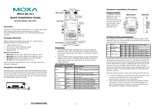
– 1 –– 2 – – 3 –P/N: 1802002112401NPort DE-211 Quick Installation GuideSeventh Edition, May 2011OverviewWelcome to Moxa’s NPort Express DE-211, a compact palm-sized data communication device that allows you to controlRS-232/422/485 serial devices over a TCP/IP based Ethernet network.Package ChecklistBefore installing the NPort Express DE-211, verify that the package contains the following items: • 1 NPort Express DE-211• NPort DE-211 quick installation guide • Documentation and software CD • Warranty cardOptional Accessories• NP21101: RS-232 cable: DB25 (M) to DB9 (F), 30 cm • NP21102: RS-232 cable: DB25 (M) to DB9 (M), 30 cm • NP21103: DB25 Terminal Block Kit for RS-422/485 •DK-35A: DIN-Rail Mounting Kit (35 mm)Notify your sales representative if any of the above items are missing or damaged.Hardware IntroductionThe NPort DE-211 device server has one female DB25 serial port. The four DIP switches located on the rear panel are used to select RS-232 COM mode, and one of four data modes: RS-232, RS-422, 4-wire RS-485, and 2-wire RS-485. See the “DIP Switch Settings and Explanation” section for details.Reset Button •Press the Reset button continuously for 3 sec to erase the password. After 3 sec, the Ready LED will flash on/off every half second. Release the reset button at this time to erase the password.•Press the Reset button continuously for 10 sec to load factory defaults. After 10 sec, the Ready LED will flash on/off every half second. Release the reset button at this time to load factory defaults.Hardware Installation ProcedurePlacement Options In addition to placing the DE-211 unit on a desktop or otherhorizontal surface, you may also make use of the DIN-Rail or Wall Mount options, as illustrated here.Wall MountDIN-RailDIP Switch Settings and ExplanationThe top panel of the DE-211 contains the following table, which describes how to set up the serial port using the four DIP switches located on DE-211’s rear panel.SW1 SerialConnection SW2 SW3 SW4Serial Interface Mode OFF OFF OFF RS-232 ONRS-232 ConsoleOFF ON ON RS-422ON OFF ON 4-wire RS-485 by RTS OFF Data CommON ON ON 4-wire RS-485 by ADDC ON OFF OFF 2-wire RS-485 by RTS ON ON OFF 2-wire RS-485 by ADDCSwitch SW1 controls the function of the serial port. Note that after changing the setting of SW1, the DE-211 will reboot to initialize the new setting. You must wait a few seconds for the green Ready light to blink off and then on again, indicating that the function of the serial port has been changed. Switches SW2, SW3, and SW4control the serial port’s data communication Interface Mode. (RTS stands for Ready To Send and ADDC stands for Automatic Data Direction Control.)Keep the following points in mind when setting the DIP switches: •To use the serial port as an RS-232 console connection, such as when using MOXA PComm Terminal Emulator or HyperTerminal, set SW1 to the ON position.•Some setup procedures can be carried out through a Telnet connection, in which case data is transmitted through the DE-211’s Ethernet port. However, you must set SW1 to the OFF position to establish a Telnet connection.owerPC– 4 – – 5 – – 6 –/supportThe Americas: +1-714-528-6777 (toll-free: 1-888-669-2872)Europe: +49-89-3 70 03 99-0 Asia-Pacific: +886-2-8919-1230China:+86-21-5258-9955 (toll-free: 800-820-5036)2011 Moxa Inc. All rights reserved.Software Installation InformationDetailed information about installing the software that comes with the DE-211 can be found on the NPort Documentation andSoftware CD in the “NPort Family Software Installation Guide”.Pin Assignments and Cable WiringFemale DB25 Connector PinoutsRS-232 WiringRS-422 WiringRS-485 WiringDB25 Terminal Block Kit (RS-422, RS-485-2W/4W)Environmental SpecificationsPower requirements 12 to 30 VDC150 mA (max.) at 12 V92 mA (max.) at 24 VOperating Temp. 0 to 55°C Ambient Relative Humidity 5 to 95% (non-condensing) Dimensions Including ears: 90.2 × 100.4 × 22 mm(3.55 × 3.95 × 0.87 in)Without ears: 67 × 100.4 × 22 mm (2.64 × 3.95 × 0.87 in)Surge Protection 15 KV ESD for the serial port Magnetic Isolation Protection 1.5 KV for the Ethernet port Regulatory Approvals FCC Class B, CE Class B, UL 60950-1, EN 60950-1。
F111F211中文说明书

i重要在使用前请认真阅读该说明书该说明书包含了关于IC-F111/F121 和IC-F211/F221的重要的使用说明名词解释警告:也许会发生身体伤害,火灾或者电击小心:也许会损害设备注意:如果不管的话,仅仅会产生麻烦。
不会发生身体伤害,火灾或者电击警惕警告!永远不要直接将电台连入直流电源,这会导致火灾或者电击。
小心!在长时间持续发射的时候不要触摸电台(尤其是热的接收器)。
因为,电台会发热。
永远不要将电台接入超过16V的直流电源,这会损坏电台。
永远不要切断直流电源插座和保险丝之间的导线。
因为可能会导致损坏电台。
永远不要把电台安装在会妨碍车辆驾驶或者会导致身体伤害的地方。
永远不允许孩子接触电台。
永远不要将电台暴露在雨、雪或者其他液体。
ii使用附带的麦克风。
其他麦克风因为接口不同或者会损坏电台不要将电台放置在环境温度低于-30℃或者高于+60℃的地方,或者放置在阳光直射的地方,例如仪表盘上。
避免关闭发动机使用电台。
在这种情况下,汽车的电池会很快耗尽电量。
避免将电台放置在灰尘过多的环境。
避免将电台放置的靠近墙壁,这会硬性散热。
避免使用汽油,酒精等有机物质清洗电台,这会损坏电台的外表。
目录第1页面板描述前面板1.音量旋钮旋转该旋钮可以调节音量。
·最小音量可以预编程。
2.功能显示显示各种信息,例如频道号/名称,5-音频码,DTMF号码和声音条件,等。
注意:以上功能需要预先编程。
3.上/下[∧]/[∨]按键选择操作频道可以编程为一个或者几个功能。
(例如P0到P3键)4.电源开关按下打开或者关闭电源·下列功能在打开电源的时候是可用的:--自动扫描开始--密码提示--设定模式第2页5.可编程按键[P0]到[P3]这些按键可以编程为您需要的功能快捷键6.麦克风接口连接附带的麦克风或者选配的具备机群功能的DTMF麦克风。
永远不要使用未经认证的麦克风。
接口可能不同,并且有可能会损坏电台。
麦克风附带的麦克风有一个PTT发射按键和一个挂钩·在麦克风拿起或者挂起时,下列功能可选:----挂起时,自动扫描。
BROCADE_交换机的配置手册1

U_Port
FL_Port
NL_Port 节点
交换机 2
NL_Port 节点
24-位 N_Port/F_Port可用范围: –x„01 0000‟到x„EF EFFF‟
结构协议 编码 / 解码 物理变换
通用服务
FC-1
FC-0
光纤物理与信号接口 ( FC- PH, FC-PH2, FC-PH3 )
FC - AL
FC - AL -2
8b/10b 编码 铜, 光连接
光纤通道的拓扑结构
Fibre Channel有三种拓扑结构:
– 点对点(Point-to-Point) – 两个设备之间互连 – 仲裁环(Arbitrated Loop) – 最多支持126个设备互连,形成一个 仲裁环 – 交换式Fabric(Switch Fabric) – 最多1千6百万个设备互连
World Wide Name (WWN) 定义
Fabric是指一个或几个可以使用目的标示来传输数据帧的交换机。 Fabric通常可以被认作是一个“云团”,也可以当作是一个虚拟连 接。每一个设备的唯一标示就是World Wide Name (就像一个人的 身份证,终身使用并不会修改)
FC标准预留
现有的网络技术状况
当信息转换成关键数据时, 网络必须进一步扩展来满足 这一新的需要: 数据 – 爆炸性的数据增长 – 动态高速的数据迁移 传输 – 安全的数据存放和读取
基于TCP/IP技术的 网络能实现这一切, 然而:
– 数据迁移一只能以异步方式进行
CMNET城域网BRAS配置规范
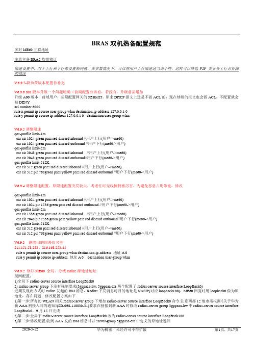
BRAS双机热备配置规范多对ME60互联地址注意主备BRAS均需修订限速设置中,对于上行和下行都设置相同值,在多数情况下,可以将用户上行限速适当调小些,这样可以降低P2P类业务上行占资源的情况V.6.9.7-降负荷版本配置待补充V6.9.6 a00版本升级一个问题明确(前期配置应该有,若没有,升级前需增加升级A00版本,前域用户,必须配置网关的PERMIT。
原来DHCP报文上送是不做ACL的,现在续租的报文也会做ACL,不配置就会被DENYacl number 6005rule x permit ip source user-group wlan destination ip-address 127.0.0.1 0rule y permit ip source ip-address 127.0.0.1 0 destination user-group wlanV6.9.5调整限速qos-profile limit-1mcar cir 1024 green pass red discard inbound //用户上行(用户->me60)car cir 1024 green pass red discard outbound //用户下行(me60->用户)qos-profile limit-2mcar cir 2048 green pass red discard inbound //用户上行(用户->me60)car cir 2048 green pass red discard outbound//用户下行(me60->用户)qos-profile limit-512Kcar cir 512 green pass red discard inbound //用户上行(用户->me60)car cir 512 pir 768green pass yellow pass red discard outbound //用户下行(me60->用户)V6.9.4调整限速配置,原限速配置突发较大,考虑忙时无线侧拥塞厉害,为避免恶意占用带宽,修改qos-profile limit-1mcar cir 1024 green pass red discard inbound //用户上行(用户->me60)car cir 1024 pir 1536 green pass red discard outbound //用户下行(me60->用户)qos-profile limit-2mcar cir 1536 green pass red discard inbound //用户上行(用户->me60)car cir 2048 pir 2536 green pass yellow pass red discard outbound//用户下行(me60->用户)qos-profile limit-512Kcar cir 512 green pass red discard inbound //用户上行(用户->me60)car cir 512 pir 768green pass yellow pass red discard outbound //用户下行(me60->用户)V6.9.3 删除旧的国漫白名单211.151.58.233、216.168.253.44rule x permit ip source user-group wlan destination ip-address 地址A 0rule y permit ip source ip-address 地址A 0 destination user-group wlanV6.9.2 修订ME60 全局、分域radius源地址地址现网配置:1)全局下radius-server source interface LoopBack02)radius-server group下没有强制要求(3gppaaa-hw, 3gppaaa-zte两个配置了radius-server source interface LoopBack0)近期发现此方式时radius发起的DM消息,Radius下发消息时目的地址是NASIP(对应loopback100),ME60回复时用loopback0做为原地址,存在问题;修改配置方案如下1)第一步:所有的WLAN相关radius-server group下增加radius-server source interface LoopBack0命令.注意西部12地市需根据《关于华为新AAA割接入网的通知》(SD-098-110830-31)要求在割接到新AAA时修改radius-server group 3gppaaa-hw中radius-server source interface LoopBack0,9月15日完成2)第二步:全局下radius-server source interface LoopBack0改为radius-server source interface LoopBack1003)第三步:修改配置,收到AAA发的DM消息时以server-group 3gppaaa-zte中定义的原地址返回radius-server authorization 211.137.187.20 shared-key 88----89 server-group 3gppaaa-hw //信任华为新AAA下发的DM消息,用于踢用户,新华为AAA.收到AAA发的DM消息时以server-group 3gppaaa-hw中定义的原地址返回radius-server authorization 211.137.183.67 shared-key 88----89 server-group 3gppaaa-zte //信任中兴AAA下发的DM消息,用于踢用户,收到AAA发的DM消息时以server-group 3gppaaa-zte中定义的原地址返回4)备用ME60按上述步骤修改修改完毕后测试内容:1)省内用户2)省外用户(或电子卡)3)计费验证4)省内用户在portal页面自助下线V6.9 新增白名单数据根据集团要求国漫新白名单:211.99.206.88、211.99.206.87、202.83.198.71 //20110908在ACL6005中增加,注意每个地址对应两条策略rule xyz(根据配置需要定数值) permit ip source user-group wlan destination ip-address x.x.x.x 0rule abc(根据配置需要定数值) permit ip source ip-address x.x.x.x destination user-group wlanV6.86.7日割接后,省内radius/portal根据强制portal页面携带SSID区分是社会热点还是校园热点1)携带SSID=CMCC-EDU,对外省用户不让使用,有提示语;对省内用户不加后缀;校园用户默认认证后域wlan-sd-new2)不携带SSID或SSID=CMCC,对外省用户不加后缀,对省内用户加后缀wlan-sd-new,仍然使用wlan-sd-new这个认证后域由此导致校园与社会热点只能用相同的限速策略。
摩托罗拉高速网络模组MB7420用户指南说明书

Quick StartCable ModemMB7420Packaged with your modemPower Cube Coax WrenchEthernet Cable Velcro® Cable TiePara una Guía de Inicio Rápido enespañol, por favor vaya a/MB7420IRLet’s get startedIf you don’t have cable modem service, please order that from your cable service provider.Now connect your modem as shown on the next panel.Connecting to a Coax Cable On the next panel you’ll need to connect your modem to a “live” coax cable. Sometimes a cable will already be available. Sometimes there’s a coax wall jack available, and you connect to the jack with a coax cable. Your modem can also share a coax cable attachedto a TV by using a coax splitter.ON/OFF button POWERConnect the supplied power cube between the power jack and an electrical outlet. RESET button ETHERNET (LAN) Here you can connect a computer, router, HDTV, game station, or other Ethernet-capable device. COAXConnect a “live” coax cable to the modem’s COAX connector as discussed above. (Tighten the nut so it’s finger tight. You maywant to use the supplied wrench. Make the connection snug but not over-tight.)Prepare to activateBy now you should have:•Subscribed to cable Internet service. •Connected your cable modem.•Powered up your cable modem. To do this, the On/Off button needs to be On. Wait for the green online connection light to stop flashing and remain solidly lit. This may take up to 15 minutes.You should have a recent cable bill handy because it has your account number and you’ll probably need that.If you’re asked for information about your cable modem, you can find this on the label on the bottom of the modem.ActivateFor some service providers, you activate by calling them. Many service providers including Comcast and Cox prefer that you activate by opening the Web browser of a computer that’s plugged into theMB7420’s Ethernet port.For Comcast XFINITY Users Only:If the activation page does not appear in your browser, please go to /internetsetup for more information and to activate your modem.If no registration page appears after following the browser instructions above, you need to contact your cable company to register your modem. Here is a listof phone numbers for some major cable service providers. (Note that this list is subject to change.)Comcast 1 (855) 652-3446Time Warner 1 (855) 704 4503Bright House 1 (888) 289-8988Suddenlink 1 (877) 794-2724Cable One 1 (877) 692 2253Cox 1 (888) 556-1193RCN 1 (866) 832-4726Once your cable modem is registered either online orby phone, your service provider will provision yourcable modem service. Typically this takes less than 5 minutes, but in some cases this may take 30 minutesor longer to complete.Once you have activated, you should have Internet access for whatever’s plugged into your cable modem. Congratulations!If your cable modem is NOT working, see Troubleshooting Tips below.If You Want to Connect a RouterThis connection is optional, done after the cable modem is activated. A wireless router lets multiple devices (computers, smartphones, tablets, video devices, game stations…) share your cable modem’s Internet connection, either wirelessly or through a direct Ethernet connection.1. The cable modem and the router should bothbe powered off. 2. Plug the cable modem’s Ethernet cable into therouter’s WAN port. (You may need to disconnect the cable from your computer first.) 3. Power-up the cable modem. Wait for theONLINE lightto be solidly lit. 4. Power-up the router. Wait for the router tocomplete its power-up sequence. 5. The LAN lighton your modem should be litto show the Ethernet connection to your router. Follow your router’s instructions for setting up the router and connected devices. Using a computer or other device connected to the router, try connecting to the Internet. If it works, Congratulations! Installation is complete.Front Panel LightsLIGHTCOLORDESCRIPTIONEthernet LANportGreen or AmberBlinking: Ethernet data is flowing Green: C onnected at highest LANspeed, 1 GbpsAmber: Connected at 10 or 100 Mbps OFF: No connectionOnlineGreenBlinking: Trying to go online ON: OnlineOFF: OfflineUpstreamGreen or BlueGreen Blinking:Ranging in progressGreen ON: Connected on 1 channel Blue Blinking: N egotiating bondedchannel(s)†Blue ON: Bonded with 2 ormore channelsOFF: Upstream not connectedDownstreamGreen or BlueGreen Blinking:Scanning for DS channel Green ON: Connected on1 downstream channelBlue Blinking: N egotiatingbonded channel(s)†Blue ON: Bonded with 2 or morechannelsPowerGreenON: Cable modem power onOFF: Cable modem power off†If a blue light blinks continuously, this indicates partial service (at least one designated channel has not completed bonding). You should still get high Internet speeds, but your service provider may want to know so they can adjust their network.Troubleshooting TipsWhat if I can’t make an Internet connection right after installation?•First turn your cable modem off for at least 8 seconds, then on, to see if that fixes the problem.•Check the connections you’ve made to your cable modem – power, Ethernet, and coax. Are those connections good? •Check that the modem’s power cube is plugged into a live outlet, and that the Ethernet cable is connected securely. •Make sure that your coax cable is live. You can check that by using it with a TV.•Check that you provided the correct setup information to your cable service provider.•Contact your cable service provider to make sure they’ve turned on your Internet service.What if my cable modem has been working, then stops working?•First turn your cable modem off for at least 8 seconds, then on, to see if that fixes the problem.•If the modem’s lights don’t come on, check that the modem is getting power from its power cube and that the modem’s power button is on.•Check your cable modem cables.•Check with your service provider. Sometimes there’s a service outage or some other service issue.What if I’m getting Internet service but my speed is disappointing?•Be sure you know what speed you’re paying for.•Check the speed with a computer plugged into the modem. Use one of the tools found when you search the phrase: broadband speed test.•If you get good speed when a computer’s plugged into the modem, you may have a router problem.•Some video streaming services get bottlenecked, especially at busy times like after dinner. See whether you have the speed problem at less busy times.•Try connecting your cable modem nearer to where the coaxial cable comes into your home. This lets you see whether your home’s cabling is a problem.•If you’re using a splitter with your cable modem, try the cable modem without the splitter to see if that helps. If it does, you may need to get a better splitter.What if I'm told that my cable modem isn't approved for my cable modem service?•That’s probably not true. Leading cable service providers have a list of certified cable modems, and you can check the list for your service provider. You can also find information about certifications at /servicesDo you have any other questions? We have lots more information at /mentorWe like to help.Please visit our support Website or call our support specialists. Our Website has our Motorola Mentor information, and also provides returns and warranty information./support Email:************************* Phone: 800-753-0797Limited WarrantyMTRLC LLC warrants this product against defects in material and workmanship for a warranty period of 2 years. To read the full warranty, please go to /warrantySafety PrecautionsThese precautions help protect you and your cable modem. Do not put the cable modem or its power cube in water, since this is a shock hazard.The cable modem should normally be installed indoors. If you use it outdoors, protect it from moisture and be careful about temperature.Your cable modem should be operated in an environment that’s between 32 and 104° Fahrenheit (0 to 40° Centigrade). Your cable modem should not be in a confined space. There should be room for air flow around the top, front, and sides of the cable modem.Make sure to use your cable modem’s power cube and a compatible electrical outlet.FCC StatementThis device complies with Class B Part 15 of the FCC Rules. Operation issubject to the following two conditions: (1) this device may not cause harmful interference, and (2) this device must accept any interference received,including interference that may cause undesired operation. Only coaxialcables are to be used with this device in order to ensure compliance with FCC emissions limits. Accessories connected to this device by the user mustcomply with FCC Class B limits. The manufacturer is not responsible for any interference which results from use of improper cables, or which results from unauthorized changes or modifications to the device.©MTRLC 2016. MOTOROLA and the Stylized M Logo are trademarks orregistered trademarks of Motorola Trademark Holdings, LLC. and are used under license. All rights reserved.27727-EL-B/3155。
Telex IP-223、N-I223和iDEN数码手机配置指南说明书

AN-DISPATCH-012 Rev A30-NOV-2009iDEN Radio Control on Legacy Tone SystemsUsing IP-223sTable of Contents1.0General (3)1.1Tone Control of iDEN (4)2.0IP-223 1 Setup (4)2.1IP-223 1 Jumper Settings (4)2.2IP-223 1 Multicast Setup (5)2.3IP-223 1 Per Line Setup (6)3.0IP-223 2 Configuration (6)3.1IP-223 2 Jumper Settings (6)3.2IP-223 2 Multicast Address Setup (iDEN Mode) (7)3.3IP-223 Per Line Setup (8)2AN-DISPATCH-012AN-DISPATCH-012 3 1.0GeneralThis application note is intended to show how to configure and connect a Telex IP-223, N-I223 and an iDEN radio to a legacy tone control system and provide direct connect control to an operator.The following features are supported using this method:•Last call -F1 can be configured to call the last unit to call in or the last outgoing call.•Up to 16 Preprogrammed Direct Connects -FTone button limit on most consoles is 16, only 15 available if the Last call function is active.•Manual Entry of Direct Connect Numbers -Possible if the console is equipped with DTMF keys A-D (direct connect # followed by the D key)•Group Calls -Possible if the console is equipped with DTMF keys A-D (direct connect group number followed by the C key) 5.•Alerts - Possible if the console is equipped with DTMF keys A-D (direct connectnumber followed by the A key)NOTE:Phone functions are not supported.FIGURE 1.Legacy Tone System to iDENiDEN Radio Control on Legacy ToneSystems Using the IP-223iDEN Radio Control on Legacy Tone Systems Using the IP-2234 AN-DISPATCH-0121.1Tone Control of iDENControl tones (2175Hz/F-tone/2175hz PTT) are generated by the legacy system either at theconsole output or at the CEB/BIN output. These tones are inserted into the first IP-223 (IP-223 1 in the following example) via 4-wire tone control where this first IP-223 is running in Console mode. The first IP-223 decodes the tones and generates TX packets to the Ethernet port. The second IP-223 (IP-223 2 in the following example), running in iDEN mode, receives the TX packets via Ethernet and sends a Direct Connect command to the iDEN radio.The iDEN radio connects to the system, provides a clear-to-talk tone which is sent back through the second IP-223’s RX circuits, generates RX packets through the Ethernet port to the first IP223 and back to console operator’s speaker via the RX input on the console system.NOTE:Both Multicast and Unicast are supported; however, only Multicast setup is discussed here. For more information about Unicast Setup, contact technical support.2.0IP-223 1 SetupIP-223 1 requires jumper and Multicast configuration for Console mode operation and line 1 settings.2.1IP-223 1 Jumper SettingsSet the jumpers of IP-223 1 to Console mode.REFERENCE:For more information, see the IP-223 Technical Manual (P/N 803641).This document is available for download at /Downloads/.iDEN Radio Control on Legacy Tone Systems Using the IP-223AN-DISPATCH-012 52.2IP-223 1 Multicast SetupTo configure IP-223 1 for Multicast, do the following:1. From the IP-223 web browser configuration window, click Multicast Setup .The Multicast setup window appears.2. Select the Enable via Ethernet for both Line Number 1 and Line Number 2.3. From the Line Type drop down menu, select Console Mode for both line 1 and line 2.4. Enter a name in the Line Name field for both line 1 and line 2.5. In the Rx Multicast field enter the same Multicast Address for both line 1 and line 2.(For example 225.8.11.81).6. In the Tx Multicast field enter the same Mulitcast Address used in the Rx Multicastfield for both line 1 and line 2. (For example 225.8.11.81).7. In line 1’s Rx Port field, enter a unique port number. (For example, 1054).8. In line 1’s Tx Port field, enter a unique port number. (For example, 1254).9. In line 2’s Rx Port field, enter a unique port number. (For example, 1055)10. In line 2’s Tx Port field, enter a unique port number. (For example 1255.11. Click Submit .The changes are temporarily saved.12. Click Save to EEPROM.The EEPROM window appears.13. Click Save Parameters .The Changes are permanently saved to IP-223 1.FIGURE 2.Multicast Address Setup—IP-223 1iDEN Radio Control on Legacy Tone Systems Using the IP-2236 AN-DISPATCH-0122.3IP-223 1 Per Line SetupTo configure IP-223 1’s Per Line Setup , do the following:1. From the IP-223 1 web browser configuration window, click Per Line Setup .The Per Line Setup window appears2. Select the Full Duplex check box.3. Select the RxAGC check boxREFERENCE:For more information, see the IP-223 Technical Manual (P/N 803641).This document is available for download at /Downloads/.3.0IP-223 2 ConfigurationIP-223 2 requires jumper and Multicast configuration for iDEN mode operation and line 1 settings.3.1IP-223 2 Jumper SettingsSet the jumpers of IP-223 2 to iDEN mode.REFERENCE:For more information, see the NI-223 Technical Manual (P/N 804165).This document is available for download at /Downloads/.FIGURE 3.Per Line Setup—IP-223 1iDEN Radio Control on Legacy Tone Systems Using the IP-223AN-DISPATCH-01273.2IP-223 2 Multicast Address SetupTo configure IP-223 2 for Multicast , do the following:1. Follow steps 1, 2, and steps 4 through 10, in “IP-223 1 Multicast Setup” on page 5.2. From the Line Type drop down menu select iDEN mode for both line 1 and line 2.3. Click Submit .The changes are temporarily saved.4. Click Save to EEPROM ,The Save to EEPROM window appears.5. Click Save Parameters.FIGURE 4.IP-223 1 Multicast Address Setup—IP-223 2 (iDEN Mode)iDEN Radio Control on Legacy Tone Systems Using the IP-2238 AN-DISPATCH-0123.3IP-223 Per Line SetupTo configure IP-223 2 Per Line Setup , do the following:1. From the web browser configuration window, click Per Line Setup .The Per Line Setup window appears.2. In the TX Delay field, enter 50 (ms).3. Click Submit .The configuration is temporarily saved.4. Click Save to EEPROM .The Save to EEPROM window appears.5. Click Save Parameters.The configuration is permanently saved to the IP-223.FIGURE 5.Per Line Setup—IP-223 2 (iDEN Mode)Revision HistoryDocument Title: iDEN Radio Control on Legacy Tone Systems Using IP-223sDocument Number: AN-DISPATCH-012Revision Change Description DateA Update brand, format and new document number.30-NOV-2009Suggestions or comments:Contact technical support with suggestions or comments concerning this application note.Technical Support:Email:*********************************.comFax:1-402-467-3279Phone:1-800-898-6723Bosch Security Systems, Inc.8601 East Cornhusker HighwayLincoln Nebraska 68507Phone: (800) 752-7560 Fax: (402) 467-3279Email:**********************.comWeb: Downloads: /Downloads/。
MOTOROLA MKP1V120 MKP1V130 数据手册

Sidac High VoltageBilateral Triggers...designed for direct interface with the ac power line. Upon reaching the breakover voltage in each direction, the device switches from a blocking state to a low voltage on-state. Conduction will continue like an SCR until the main terminal current drops below the holding current. The plastic axial lead package provides high pulse current capability at low cost. Glass passivation insures reliable operation. Applications are:•High Pressure Sodium Vapor Lighting•Strobes and Flashers•Ignitors•High Voltage Regulators•Pulse GeneratorsMAXIMUM RATINGS (T = 25°C unless otherwise noted)THERMAL CHARACTERISTICS Order this document by MKP1V120/DMOTOROLA SEMICONDUCTOR TECHNICAL DATA 查询MKP1V120供应商MKP1V120 MKP1V130ELECTRICAL CHARACTERISTICS (T C = 25°C unless otherwise noted; both directions)CharacteristicSymbol Min Typ Max Unit Breakover VoltageMKP1V120MKP1V130V BO110120——130140VoltsRepetitive Peak Off-State Current(60 Hz Sine Wave, V D = Rated V DRM )T J = 125°CI DRM ————550µA Forward “On” Voltage (I TM = 1 A)V TM — 1.3 1.5Volts Dynamic Holding Current I H ——100mA Switching Resistance R S 0.1——k ΩBreakover CurrentI BO ——200µA Maximum Rate-of-Change of On-State Current MKP1V120, 130,di/dt—90—A/µs Figure 1. Maximum Lead TemperatureFigure 2. Maximum Ambient TemperatureFigure 3. Typical On-State Voltage Figure 4. Power Dissipation2.01.003.04.00.2107.05.03.02.01.00.70.50.30.1125°CT J = 25°C5.0V T , INSTANTANEOUS ON-STATE VOLTAGE (VOLTS)1.000.20.40.60.800.500.250.751.25 1.0T J = 25°CConduction Angle = 180°CI T(RMS), ON-STATE CURRENT (AMPS)130405060708090100110120 1.814000.20.40.60.8 1.0 1.2 1.4 1.6 2.0T LI T(RMS) ON-STATE CURRENT (AMPS)0.8T J = 125°C Sine WaveConduction Angle = 180°0.20.41200.60204060801001.0Assembled in PCB Lead Length =T J = 125°CSine WaveConduction Angle = 180°140T A , MAXIMUM AMBIENT TEMPERATURE (°C)3ń8″3ń8″3ń8″T , M A X I M U M A L L O W A B L E L E A D T E M P E R A T U R E ( C )L °I , O N -S T A T E C U R R E N T (A M P S )T (R M S )I , I N S T A N T A N E O U S O N -S T A T E C U R R E N T (A M P S )T P , P O W E R D I S S I P A T I O N (W A T T S )R M SMKP1V120 MKP1V130THERMAL CHARACTERISTICSFigure 5. Thermal ResponseFigure 6. Breakover Voltage Figure 7. Holding CurrentTYPICAL CHARACTERISTICSFigure 8. Pulse Rating Curve Figure 9. V-I Characteristics10%1.010101.00.1I PKtwt w , PULSE WIDTH (ms)100100 1.2–60–400.40.60.81.01.41000.20.5 1.0 2.0 5.0102050 2.0 k 200t, TIME (ms)1.0 k 500 5.0 k 10 k0.050.010.020.030.70.070.10.20.50.31.00.1T J , JUNCTION TEMPERATURE (°C)–20140120100806040T J , JUNCTION TEMPERATURE (°C)Slope = R SI SV SI (BO)V (BO)V DRMI DRMI TM V TMI H200.801.00.9120–20020*********–60140–40The temperature of the lead should be measured using a thermocouple placed on the lead as close as possible to the tie point. The thermal mass connected to the tie point is normally large enough so that it will not significantly respond to heat surges generated in the diode as a result of pulsed operation once steady-state conditions are achieved. Using the measured value of T L , the junction temperature may be deter-mined by:T J = T L + ∆T JLR S +(V (BO)*V S )(I S *I (BO))V , B R E A K O V E R V O L T A G E (N O R M A L I Z E D )B Or (t ), T R A N S I E N T T H E R M A L R E S I S T A N C E (N O R M A L I Z E D )I , P E A K C U R R E N T (A M P S )PK I , H O L D I N G C U R R E N T (N O R M A L I Z E D )H Z θJL (t) = R θJL • r(t)∆T JL = P pk R θJL [r(t)]where:∆T JL = the increase in junction temperature above the lead temperaturer(t) = normalized value of transient thermal resistance at time, t from this figure. For example,r(t p ) = normalized value of transient resistance at time t p .TIMEt p。
MOTOAP配置手册

MOTOAP配置手册目录一、如何登录新设备 (2)二、配置国家代码和时钟 (7)三、配置wlan中的SSID及加密方式和密码及应用wlan (8)四、配置DHCP地址池及应用 (13)五、配置设备的管理IP (14)六、开启独立AP虚拟控制器功能 (16)七、如何恢复出厂 (17)八、AP如何升级软件版本 (18)一、如何登录新设备1、没有配置的情况下,用设备背面的MAC地址后四位算默认地址默认地址为,169.254.X.XX为MAC地址后4位(2位一组16进制),换算为10进制如:MAC,5C:0E:8B:07:D4:2FD4=2122F=47默认IP为:169.254.212.47,子网掩码为24位换算好之后设置与之相连的PC的IP,这里以win7系统为例然后在DOS界面ping测试2、登录设备(一)web登录:建议选用火狐浏览器在地址栏键入https://169.254.XXX.XXX(注意用https)用算出的地址登陆,需要安装JAVA插件,由于IE9有兼容性问题,建议用火狐浏览器打开。
用默认用户名:admin,密码:motorola.登陆(Login)默认用户名为:admin,密码为:motorola.首次登陆会提示修改密码输入需要的密码,应用(Apply)密码修改成功主界面(二)命令行登录:默认为ssh2登录,有console口的可以选用console登录,波特率为19200. 这里选用登录工具为SercureCRT进入命令行二、配置国家代码和时钟Web界面配置:进入’Configuration’—‘Devices’—‘RF Domain’—‘Basic Configuration’设置地区(Country)和Time Zone 点右下角’OK’,点右上角’Commit and save’注意:不设置地区,一切其他设置都无效,不点’Commit and save’设置不生效.命令行配置三、配置wlan中的SSID及加密方式和密码及应用wlanWeb配置进入’Configuration’—‘Wireless LANs’.点’add’,依次填入WLAN名称,SSID,VLAN号,点’OK’.点击Security,依次选着加密方式和填写所需密码,点击OK,最后点击右上角commit and save.独立AP模式下以下两种方式都可,任选一种方式一:完毕后点击右上角commit and write命令行配置wlan的SSID及加密方式和密码:应用wlan方式一方式二四、配置DHCP地址池及应用(一般情况下,如客户内网有DHCP且不是测试的情况下,无需配置DHCP)Web配置:configuration-services-dhcp server –勾选dhcp dhcp server police点击add,在弹出的界面添加对应的地址池名称,网段,网关,DNS,和地址集。
MOTO WLAN 摩托罗拉 AC快速配置指南

Motorola 摩托罗拉无线交换机RFS7000/WS5100v3.x(以下配置以RFS7000为例)快速配置目录快速配置指南 (3)1 特别注意 (3)2 AC配置前准备工作 (3)3 AC基础配置 (4)1.1 初次登录 (4)***CLI 命令行指令概述 (7)1.2 VLAN及IP地址配置 (9)1.3 WLAN设置(含HOTSPOT配置) (12)1.4 AP300设置及状态检查 (18)1.5 接入终端状态检查 (22)1.6 配置DHCP服务 (23)1.7 配置静态路由 (25)1.8 配置冗余热备 (27)4 密码恢复 (29)5 版本升级 (31)CLI命令行说明 (34)参考拓扑 (38)设备维护指南 (39)1 日例行工作 (39)1.1 机房温湿度检查。
(39)1.2 电源设备检查。
(39)1.3 设备供电情况检查(白班、夜班各一次)。
(39)1.4 设备状态检查(白班、夜班各一次)。
(39)1.5 设备告警信息(白班、夜班各一次) (42)1.6 AP在线检查(白班、夜班各一次) (43)1.7 检查各接入点登录网络的用户状态 (44)1.8 检查DHCP SERVER服务器运行状态(3层部署时需要) (44)2 周例行工作 (45)2.1 故障统计汇总(每周一)。
(45)2.2 备份电子版维护作业计划执行记录(每周五)。
(45)3 月例行工作 (45)3.1 WLAN MOTO设备配置文件备份。
(45)3.2 传输资料的检查核对 (45)3.3 AP终端运行情况检查 (45)3.4 标签检查 (45)3.5 进行系统设备巡检 (45)快速配置指南1 特别注意关机必须要先用halt命令停止系统。
2 AC配置前准备工作Hardware需求:AC及安装附件一套标准220V交流电源线一根Console cable一条台式机或笔记本电脑一台,配有以太网端口(100Mbps/1000Mbps以太网网卡)RJ45交叉网线1条(568B and 568A)Software需求:超级终端软件标准WEB浏览器,IE and etc,.Java Environment,Version 1.5 or laterMotorola AC的参数配置可以通过两种方式(LAN和CONSOLE)进行配置。
V11.1双机配置手册

V11.1双机配置手册工作:一、准备软件版本至V11.1,并打上最新的Hotfix。
升级主机配置:Vlan,SelfIP配置:细的介绍注意:Floating IP 不再具有Unit ID,而是从属于Traffic Group,之后会有详境没有串口心跳线,所以采用Network Failover,所以同步的vlan 要打开默认没由于当前环有开放的unicast 端口1026。
建立一个Virtual Server :二、Device Group 配置:v11 版本中的一个重要变化,是改变了之前版本A/A, A/S 模式的双机结构,将系统现:A/A/S, A/S/S, A/A/A/A, A/A/A/S, A/A/S/S可以实N+M 模式,也就是说的冗余扩展为设备模式。
并且引入了一个概念叫做Device Group,就是一组f5同步、切换等多种主备备。
的集合,最多可以支持32台设备信息:项可以看到当前的设情况下点击默认D evice选在Device Connectivity 里面,预使用先配置用做双机的Vlan,SelfIP,Network Failover (建议U nicast network failover )以及Mirroring 地址业务口+管理口两组书,如果是两台设备做主备交换的证或双活,选择P eer Authority Devices 两台设间备之行操作:对Device Group进备上都可以针方式,在两台设端地址,用户名和密码入输对C reate:建Device Group,点击之后创证书交换Group类型选择Sync-failover,要求两台设备的型号,软件版本一致!备当前的两台设选择N etwork Failover勾选Device Group 建立完成之后,可以在Device 里看到对端状态,下图是正常的主备状态:一致:态备备机状态为灰色Standby,与Device 里看到的设状此时行双机的初始化同步,同步的方向与V9、V10 相同:左上角会提示进备机上也可以看到之前创,此时行同步之后,同步状态变成In Sync状态按照正确的方向进建的VS:成Changes Pending,需要再次同步:随意修改一些配置信息,同步状态再次变结构的双机就配置完成了。
MOTOTRBO Connect Plus多站数字通信系统说明书

MOTOTRBO CONNECT PLUSBROCHUREREACH EvERyONE EvERyWHERE THEy GOYour large workforce is out in the field every day, filling pot holes, repairing stop lights, fixing water main breaks, making deliveries or quickly restoring electricity after a storm, so you need to be able to connect with them no matter where their job takes them. MOTOTRBO Connect Plus multi-site digital trunking is a two-way radio system that enables you to accommodate the high volume, wide area communication that’s required for your business.Whether you need coverage at a single site or across multiple sites, Connect Plus can be scaled to meet your communication needs. Your work teams can not only talk to one another or the main facility, they can also use data applications to make their job more efficient and safe, including text messaging, location tracking and dispatch console capability. All the while, you gain the added benefits of TDMA digital technology like increased capacity and clear audio.MAKE yOUR MOvE AT yOUROWN PACEKeeping operations running smoothly while upgradingyour communication systems is vital to business. Thatis why MOTOTRBO radios are flexible. They can beconfigured to operate in analogue mode on your existinganalogue trunking system or in digital mode on your newMOTOTRBO system.Then, as you are ready, radios can be upgraded and youcan begin migrating one talk group or one department ata time over to MOTOTRBO Connect Plus.By migrating at your own pace, the risk of a hard cutoveris eliminated, significantly reducing the impact to yourbusiness. At the same time, you are able to spread thecost of new equipment as your budget allows.STAy IN TOUCHNO MATTER WHERE THEy’RE HEADEDWhen your fleet hits the road in the morning, centralized dispatch keeps them within reach no matter where they go. When you need multiple drivers to pick up unscheduled loads all at the same time, one dispatcher can coordinate their routes and schedules to keep the freight flowing. Dynamic roaming automatically switches to the strongest available signal as work crews travel from zone to zone, and the transfer is seamless with no interruptions. In urgent situations, workers can send emergency notification to dispatch or with the man-down application, the tilt, motion or lack of activity on a radio can be detected to automatically send emergency notification to dispatch. And for routine or low priority messaging, you can text so drivers can read it at their convenience without distracting them while in traffic.High system availabilityThe dedicated control slot makes it possible for you to quickly access voice and data communication even during high traffic times.Automatic channel accessInstead of trying again and again to place a call or to send data, calls are queued during busy times until an open channel is available. You’re then automatically notified that you can complete your call.fast access for those who need it mostWhen all channels are busy, Connect Plus will place calls in a queue and you can assign important users like managers or security personnel a priority status so they have fast access when the system is in high demand.No need to change channelsAs you travel from one site to the next, you can keep your focus on the job instead of hassling with manual site changes. Dynamic site roaming automatically registers you with the nearest site so you can travel and always stay connected.Greater system efficiencyUsers will only register with the nearest site controller rather than all the controllers in the system. This dynamic site assignment makes the system far more efficient. It uses only those resources that are needed at each site to complete your call, so the overall capacity of your system is increased.Save on infrastructureTo protect your investment in IT and IP (Internet Protocol) infrastructures, you can link multiple sites together using the technology you already have.Easy administrationThe network manager interface makes it simple to bring new radios on line, to adjust priority levels and to monitor activity in real time and on a historical basis.High securityA three-level check helps to prevent unauthorized users from accessing the system while the network manager’s disable feature makes it easy for you to remotely deactivate a lost or stolen radio. And you can control access to specific sites with site restriction capability. No downtimeThe redundant controller and rotating control channel provide back-up capability to help minimize system down time. Seamless maintenance makes it possible to update radio records, add radios or even add sites without disrupting business activity.BE MORE EffICIENT.BE BETTER CONNECTED.When your fleet is dispatched across the city and your workers are miles apart, you need a way to stay connected. MOTOTRBO Connect Plus multi-site trunking extends digital voice and data communication to as many as 29 talk paths and 2,900 users per site, so no matter where your workforce goes, they can be reached – making them moreefficient and safer in the process.CENTRALIzED ACCESS TO yOUR WORKfORCEKeeping connected with a large workforce operating in the field is vital to keeping your business productive and your workers safe. With an IP-based wire-line console, you can have centralized dispatch capability for visibility and access to your mobile work teams no matter where the job takes them. When an urgent customer pick-up request comes into the office, dispatch can quickly locate the nearest driver and efficiently direct them to your customer’s location. When your road repair crew finds a water main break across the city, dispatch can quickly contact the water department to turn off water flow to that area. Or when a sub-station loses power, dispatch can connect the field repairman with the main facility to assist with the repair.ExPERIENCE COMMUNICATIONS WITH NO LIMITSMOTOTRBO Connect Plus makes it possible to expand your communications far beyond just voice. Integrated data applications give your workforce access to real-time information. Your workers get great convenience, and you avoid purchasing, installing and maintaining additional equipment.This system supports text messaging for greater ease, accuracy and worker safety. For example, drivers can send a text confirmation when a customer delivery has been completed. Or when your work crew is perched twenty feet above the road repairing a traffic signal, you can send directions to the next job without distracting them from the one they are on.To provide better, faster service, radios are equipped with an integrated GPS module. When used with a location tracking application, you can locate people and assets with a glance. This makes it easier to better manage your mobile work force. For example, you can quickly respond to incidents by locating the nearest employee and dispatching them to the scene. It also makes it easier to manage your fleet so you can make deliveries and drive routes more efficiently.MOTOTRBO Connect Plus will have access to the industry’s largest application developer programme. There are dispatch consoles to manage your fleet, network monitoring for system maintenance and improvement, work order ticket applications, email gateways and many more.CREATE A SAfER WORK ENvIRONMENT Clearer, faster and more versatile communication isthe critical foundation for a safe workplace. Clear audio is easier to understand and minimizes confusion. Dispatchers using GPS location tracking can quickly locate the closest vehicle or personnel to send when assistance is needed, and supervisors and managers can be equipped with priority access to communication during an emergency. Instead of interrupting drivers or machine operators with a call, text messaging provides the information they need at a time when it is safe to read. And seamless roaming keeps drivers’ attention focused on the road instead of switching radio channels as they travel throughout the coverage area.ACHIEvE PERfORMANCE-CHANGING EffICIENCyWhen your mobile workforce is well connected, it is far easier for them to quickly address customer requests, handle tasks and complete repairs. And MOTOTRBO Connect Plus is so rich, so robust and so flexible, it has the potential to fundamentally change how employees are able to do their job.MOTOTRBO Connect Plus provides you withthe convenience of digital-clear voice and data communication in one device. Not only can you talkwith your work force across a wide area, you can text your driver with directions to the next repair location and spot your employees in the field easier with GPS location tracking for quicker response to customer requests. Communication for your entire work area can be centralized through a dispatch console for unparalleled efficiency. And you can use the network manager for simple and seamless maintenance, without disrupting anybusiness activity.•T DMA 2:1 technology• Available in UHF and VHF frequency bands•S upports third party applications such as IP dispatch console with XRT 9000 gateway • Peer site controller based architecture• Uses rotating control channel (talk path)• Redundant controller• 15 repeaters per trunking site (29 voice/data talk paths)• 35 trunking sites in a flexible system topology• IP (Internet Protocol) site connectivity• Supports DR 3000 or MTR3000 repeaters• GPS-based location tracking (optional)• PTT-ID• Dynamic site assignment• Site registration• Automatic site roaming• Busy queuing and call back with user priority levels• Selective call and call alert• Multi-group call• Radio disable/enable• Radio check• ESN system access verification• Emergency operation• Talk group scan• Site restriction• Optional man-downGET THE POWER TO GET THE LIGHTS BACK ONAfter the storms blew in, the lights went out and across the county 5,000 homes were in the dark. To get downed power lines back up quickly, you need to see which workers are closest to the scene and the fastest way to get them to the next critical outage. GPS equipped MOTOTRBO Connect Plus radios can show you at a glance where your crews are located, and wide area communication assures that you can reach them quickly and clearly.MOTOTRBO CONNECT PLUSFEATURESMOTOTRBO PROfESSIONAL DIGITAL TWO-WAy RADIO SySTEMYou get enhanced features, increased capacity, voice clarity, and an incredible array of integrated data applications when you make the switch to MOTOTRBO. Choose from a great selection of MOTOTRBO portable and mobile two-way radios as well as accessories so you can tailor your system to fit your business perfectly.•T DMA technology delivers twice the calling capacity of FDMA and analogue radios for the price of one frequency licence.•I nfrastructure costs are half of FDMA-based digital systems because a second call doesn’t need a second repeater.•T ext messaging, GPS-enabled applications and more are integrated to raise your communication to a new level.•S tatic and noise are rejected to make voice communication remarkably clear.• F actory Mutual (FM) certified models available.•M eets demanding IP57 specifications for submersibility in water as well as U.S. Military Standard MIL-STD-810 and the Motorola-unique ALT standard for durability and reliability.•P rovides easy migration from analogue to digital because it can operate in both modes.•L onger talk time and clearer audio are possible because of Motorola’s state-of-the-art IMPRES™technology.• C omplement your MOTOTRBO radio with a complete portfolio of Motorola Original® audio, battery, charging, carrying and mounting accessories.•F ully backed by a two-year standard warranty with 1-year warranty for batteries and accessories.•F or complete peace of mind, Service from the Start provides multi-year coverage against normal wear and tear - and more. It offers fast repair turnaround times and expert telephone technical support; all backed by Motorola’s globally integrated services infrastructure, highly qualified support technicians and certified repair facilities. Service from the Start with Comprehensive Coverage provides even greater support with the additional benefit of coverage against accidental breakage.For more information on how to make your business more efficientand better connected, visit /mototrbo or findyour closest Motorola representative or authorised Partner at/Business/XU-EN/Contact_UsMOTOROLA, MOTO, MOTOROLA SOLUTIONS and the Stylized M Logo are trademarks or registered trademarksof Motorola Trademark Holdings, LLC and are used under license. All other trademarks are the property of theirrespective owners. © 2012 Motorola Solutions, Inc. All rights reserved.Motorola Solutions Ltd. Jays Close, Viables Industrial Estate, Basingstoke, Hampshire, RG22 4PD, UKEMEA version 1 (07/2012)Distributed by:。
1+1直接冗余并机系统的运行过程

1+1直接冗余并机系统的运行过程2010-09-16 17:03:29 作者:佚名出处:机房360责任编辑:毅然转播到腾讯微博分享至新浪微博数码氏社区下载手机软件游戏看书看电影aFocus整合区域市场助您爆发“圈羊革命”在并联冗余配置方案中,当单个UPS模块出现故障时,无需将关键负载转换到市电。
所有UPS的用途都在于从根本上消除市电变化及断电的影响。
随着数据重要程度的提高以及风险承受能力的降低,转换到静态旁路和维护旁路的理念已逐渐被视为应淘汰之举。
但N+l系统设计仍需静态旁路,而且大多数N+l 系统都具有维护旁路,因为它们仍起着举足轻重的作用。
在并联冗余配置方案中,多个并联的容量相同的UPS模块共用一条输出总线。
如果"备用的"电量至少等于一个系统模块的容量,则系统为N+l冗余;如果备用的电量等于两个系统模块的容量,则系统为N+2冗余;以此类推。
并联冗余系统要求采用同一制造商生产的相同容量的UPS模块。
I几S模块制造商还可以提供系统并联电路板。
并联电路板可能包含与各个UPS模块相通的逻辑电路,且各个UPS模块之间也相互连接,以产生完全同步的输出电压。
并联总线应具备监控功能,以显示系统负载以及系统的电压与电流特征。
此外,并联总线还必须能显示并联总线上的模块数量以及需要多少模块才能保证系统冗余。
一条公共总线上可以并联的UPS模块的数量存在逻辑上限,对于不同的UPS制造商而言,该最大值也不同。
在工常运行条件下,并联冗余设计中的UPS模块均匀分摊关键负载容量。
如果从并联总线上取下一个模块进行维修(或者如果某个模块因内部故障而停机),则剩下的UPS模块必须立即承担起发生故障的UPS模块的负载。
由于有了此功能,因此可以从总线中取下任意一个模块进行修理,而无需将关键负载直接连接到无保护的市电上。
在"N+l"系统配置方案中,UPS容量可以随负载的增长而增长。
应当设置容量管理机制,以便当容量百分比达到某个水平时,就应当添加新的冗余模块。
- 1、下载文档前请自行甄别文档内容的完整性,平台不提供额外的编辑、内容补充、找答案等附加服务。
- 2、"仅部分预览"的文档,不可在线预览部分如存在完整性等问题,可反馈申请退款(可完整预览的文档不适用该条件!)。
- 3、如文档侵犯您的权益,请联系客服反馈,我们会尽快为您处理(人工客服工作时间:9:00-18:30)。
XXX地市升级221版本的“N+1”冗余配置手册此文档主要增加了两处配置:——1. 在配置Redundancy时,需要主备AC之间互指,主AC和主AC之间也要互指——2. Wireless下cluster-master-support enable 可看到全局的radiono cluster-master-support enable 只能看到本AC的radio一、配置目前RFS7000的版本存在着”N+1”冗余切换的问题,现RFS7000-4.0.1.2-221CR.img的版本已经解决了此问题,但是在使用此版本时请注意以下事项:1.Standby AC上需要使用最小的IP地址去和其他的Primary AC进行Redundancymember的建立。
如果Standby AC没有最小的IP地址,那么就需要局方提供一个最小的地址,配置到Standby AC上(类似于Loopback地址)需要路由出去。
(需要提前向局方申请)最小地址——是指在Redundancy Cluster 里的最小。
2. 在配置Redundancy时,需要主备AC之间互指,主AC和主AC之间也要互指2.对Redundancy Cluster里的所有AC的Radio进行统一的规划和部署3.对Redundancy Cluster里的所有AC的WLAN进行统一的规划和部署4.在Standby AC 配置manual mapping配置参考:上图中采用两主一备的冗余方式,备机的IP地址是58.215.72.218,在Redundancy Cluster里是最大的,如果用这个地址去建立Redundancy关系就会有问题,我们采用以下步骤解决:1. 需启用一个最小的IP地址在备机上:(需要提前向局方申请并路由此地址)AC:58.215.72.218interface vlan5ip address 5.5.5.1/302. 用这个最小的地址去建立冗余关系AC:58.215.72.218 (standy)redundancy interface-ip 5.5.5.1redundancy mode standbyredundancy auto-revert enableredundancy auto-revert-period 2redundancy dhcp-server enableredun dhcp-force-electionredundancy member-ip 58.215.72.202redundancy member-ip 58.215.72.206redundancy enableAC:58.215.72.202(primary)redundancy interface-ip 58.215.72.202redundancy member-ip 58.215.72.206redundancy dhcp-server enableredun dhcp-force-electionredundancy member-ip 5.5.5.1redundancy enableAC:58.215.72.206(primary)redundancy interface-ip 58.215.72.206redundancy member-ip 58.215.72.202redundancy dhcp-server enableredun dhcp-force-electionredundancy member-ip 5.5.5.1redundancy enable3. 建立成功以后,在主AC上看到的DHCP 的状态是Standby,备AC上看到的是Running AC:58.215.72.218 (standy)Standby-218#sh dhcp statusDHCP Server is Running on following interfacesvlan218Standby-218#AC:58.215.72.202(primary)202(config)#sh dhcp statusDHCP Server is in Standby202(config)#AC:58.215.72.206(primary)206(config)#sh dhcp statusDHCP Server is in Standby206(config)#4.冗余关系建立,查看Radio和 show run,可以查看到整个Cluster里的Radio,这时要求对整个Cluster里的Radio进行统一的规划,否则可能会造成冲突。
Wireless下cluster-master-support enable 可看到全局的radiono cluster-master-support enable 只能看到本AC的radioAC:58.215.72.218 (standy)Standby-218#sh wireless radioIDX AP MAC RADIO-BSSID TYPE STATE CHANNEL POWER ADOPTED-BY1 00-23-68-23-06-80 00-23-68-08-DB-50 11bg normal 1 (rnd) 20(20) 58.215.72.2022 00-15-70-A3-62-27 00-15-70-AA-A2-10 11bg normal 11 (rnd) 20(20) 58.215.72.2023 00-15-70-A3-5E-D2 00-15-70-AA-97-F8 11bg normal 1 (rnd) 20(20) 58.215.72.2064 00-23-68-23-0A-FD 00-23-68-09-16-CC 11bg normal 6 (rnd) 20(20) 58.215.72.206Standby-218#Standby-218#sh run | b wirelesswirelesssecure-wispe-default-secret 0 defaultSmax-users 8192manual-wlan-mapping enableload-balance by-countwlan 1 enablewlan 1 ssid moto-202wlan 2 enablewlan 2 ssid moto-206radio add 1 00-23-68-23-06-80 11bg ap300radio 1 description xxxxxradio 1 radio-number 1radio 1 bss 1 1radio add 2 00-15-70-A3-62-27 11bg ap300radio 2 radio-number 1radio 2 bss 1 1radio add 3 00-15-70-A3-5E-D2 11bg ap300radio 3 radio-number 1radio 3 bss 1 2radio add 4 00-23-68-23-0A-FD 11bg ap300radio 4 radio-number 1radio 4 bss 1 2radio default-11a bss 1 1radio default-11a bss 2 2radio default-11b bss 1 1radio default-11b bss 2 2radio default-11bg bss 1 1radio default-11bg bss 2 2radio default-11an bss 1 1radio default-11an bss 2 2radio default-11bgn bss 1 1radio default-11bgn bss 2 2no ap-ip default-ap switch-ip smart-rfradio 1 radio-mac 00-23-68-08-DB-50radio 3 radio-mac 00-15-70-AA-97-F8radio 4 radio-mac 00-23-68-09-16-CC!AC:58.215.72.202(primary)202(config)#sh wireless radioIDX AP MAC RADIO-BSSID TYPE STATE CHANNEL POWER ADOPTED-BY1 00-23-68-23-06-80 00-23-68-08-DB-50 11bg normal 1 (rnd) 20(20) 58.215.72.2022 00-15-70-A3-62-27 00-15-70-AA-A2-10 11bg normal 11 (rnd) 20(20) 58.215.72.2023 00-15-70-A3-5E-D2 00-15-70-AA-97-F8 11bg normal 1 (rnd) 20(20) 58.215.72.2064 00-23-68-23-0A-FD 00-23-68-09-16-CC 11bg normal 6 (rnd) 20(20) 58.215.72.206202(config)#202(config)#sh run | b wirelesswirelesssecure-wispe-default-secret 0 defaultSmax-users 8192wlan 1 enablewlan 1 ssid moto-202radio add 1 00-23-68-23-06-80 11bg ap300radio 1 description xxxxxradio 1 radio-number 1radio add 2 00-15-70-A3-62-27 11bg ap300radio 2 radio-number 1radio add 3 00-15-70-A3-5E-D2 11bg ap300radio 3 radio-number 1radio add 4 00-23-68-23-0A-FD 11bg ap300radio 4 radio-number 1no ap-ip default-ap switch-ipsmart-rfradio 1 radio-mac 00-23-68-08-DB-50radio 2 radio-mac 00-15-70-AA-A2-10radio 4 radio-mac 00-23-68-09-16-CC!wirelessAC:58.215.72.206(primary)206(config)#sh wireless radioIDX AP MAC RADIO-BSSID TYPE STATE CHANNEL POWER ADOPTED-BY1 00-23-68-23-06-80 00-23-68-08-DB-50 11bg normal 1 (rnd) 20(20) 58.215.72.2022 00-15-70-A3-62-27 00-15-70-AA-A2-10 11bg normal 11 (rnd) 20(20) 58.215.72.2023 00-15-70-A3-5E-D2 00-15-70-AA-97-F8 11bg normal 1 (rnd) 20(20) 58.215.72.2064 00-23-68-23-0A-FD 00-23-68-09-16-CC 11bg normal 6 (rnd) 20(20) 58.215.72.206206(config)#206(config)#sh run | b wirelesswirelesssecure-wispe-default-secret 0 defaultSmax-users 8192wlan 2 enablewlan 2 ssid moto-206radio add 1 00-23-68-23-06-80 11bg ap300radio 1 description xxxxxradio 1 radio-number 1radio add 2 00-15-70-A3-62-27 11bg ap300radio 2 radio-number 1radio add 3 00-15-70-A3-5E-D2 11bg ap300radio 3 radio-number 1radio add 4 00-23-68-23-0A-FD 11bg ap300radio 4 radio-number 1radio 4 antenna-mode primaryno ap-ip default-ap switch-ipsmart-rfradio 2 radio-mac 00-15-70-AA-A2-10radio 3 radio-mac 00-15-70-AA-97-F8radio 4 radio-mac 00-23-68-09-16-CC!wireless5.对Radio的统一规划和部署上图中,每个AC有两个单频的AP,那么AC-202和AC-206的Radio索引可以相互错开使用AC:58.215.72.218 (整个cluster的radio 都要在备机上配置)radio add 1 00-23-68-23-06-80 11bg ap300radio 1 description xxxxxradio 1 radio-number 1radio add 2 00-15-70-A3-62-27 11bg ap300radio 2 radio-number 1radio add 3 00-15-70-A3-5E-D2 11bg ap300radio 3 radio-number 1radio add 4 00-23-68-23-0A-FD 11bg ap300radio 4 radio-number 1radio 4 antenna-mode primaryAC:58.215.72.202 (primary)radio add 1 00-23-68-23-06-80 11bg ap300radio 1 description xxxxxradio 1 radio-number 1radio add 2 00-15-70-A3-62-27 11bg ap300radio 2 radio-number 1AC:58.215.72.206 (primary)radio add 3 00-15-70-A3-5E-D2 11bg ap300radio 3 radio-number 1radio add 4 00-23-68-23-0A-FD 11bg ap300radio 4 radio-number 1radio 4 antenna-mode primary6.对WLAN的统一规划和部署如果AC-202的WLAN 1 的SSID是MOTO-202,AC-206的WLAN 1 的SSID是MOTO-206那么当切换到备机上该如何配置呢?我们建议也是相互错开配置。